EP2264937A2 - Method and apparatus for generating a dedicated reference signal - Google Patents
Method and apparatus for generating a dedicated reference signal Download PDFInfo
- Publication number
- EP2264937A2 EP2264937A2 EP10166623A EP10166623A EP2264937A2 EP 2264937 A2 EP2264937 A2 EP 2264937A2 EP 10166623 A EP10166623 A EP 10166623A EP 10166623 A EP10166623 A EP 10166623A EP 2264937 A2 EP2264937 A2 EP 2264937A2
- Authority
- EP
- European Patent Office
- Prior art keywords
- sequence
- drs
- generating
- initialization
- mimo
- Prior art date
- Legal status (The legal status is an assumption and is not a legal conclusion. Google has not performed a legal analysis and makes no representation as to the accuracy of the status listed.)
- Granted
Links
- 238000000034 method Methods 0.000 title claims abstract description 48
- 238000004891 communication Methods 0.000 claims description 3
- 230000007480 spreading Effects 0.000 abstract description 43
- 230000005540 biological transmission Effects 0.000 description 47
- 101150071746 Pbsn gene Proteins 0.000 description 31
- 238000013507 mapping Methods 0.000 description 15
- 201000000913 Duane retraction syndrome Diseases 0.000 description 12
- 238000000162 direct recoil spectroscopy Methods 0.000 description 12
- 108010001267 Protein Subunits Proteins 0.000 description 6
- 230000008569 process Effects 0.000 description 4
- 238000007796 conventional method Methods 0.000 description 2
- 230000003247 decreasing effect Effects 0.000 description 2
- 238000011156 evaluation Methods 0.000 description 2
- 230000007774 longterm Effects 0.000 description 2
- 125000004122 cyclic group Chemical group 0.000 description 1
- 238000005516 engineering process Methods 0.000 description 1
- 230000003993 interaction Effects 0.000 description 1
- 238000012986 modification Methods 0.000 description 1
- 230000004048 modification Effects 0.000 description 1
- 238000012545 processing Methods 0.000 description 1
- 230000011664 signaling Effects 0.000 description 1
- 230000001131 transforming effect Effects 0.000 description 1
Images


Classifications
-
- H—ELECTRICITY
- H04—ELECTRIC COMMUNICATION TECHNIQUE
- H04L—TRANSMISSION OF DIGITAL INFORMATION, e.g. TELEGRAPHIC COMMUNICATION
- H04L5/00—Arrangements affording multiple use of the transmission path
- H04L5/003—Arrangements for allocating sub-channels of the transmission path
- H04L5/0053—Allocation of signaling, i.e. of overhead other than pilot signals
-
- H—ELECTRICITY
- H04—ELECTRIC COMMUNICATION TECHNIQUE
- H04B—TRANSMISSION
- H04B7/00—Radio transmission systems, i.e. using radiation field
- H04B7/02—Diversity systems; Multi-antenna system, i.e. transmission or reception using multiple antennas
- H04B7/04—Diversity systems; Multi-antenna system, i.e. transmission or reception using multiple antennas using two or more spaced independent antennas
- H04B7/0413—MIMO systems
- H04B7/0452—Multi-user MIMO systems
-
- H—ELECTRICITY
- H04—ELECTRIC COMMUNICATION TECHNIQUE
- H04L—TRANSMISSION OF DIGITAL INFORMATION, e.g. TELEGRAPHIC COMMUNICATION
- H04L27/00—Modulated-carrier systems
- H04L27/26—Systems using multi-frequency codes
- H04L27/2601—Multicarrier modulation systems
- H04L27/2602—Signal structure
- H04L27/261—Details of reference signals
-
- H—ELECTRICITY
- H04—ELECTRIC COMMUNICATION TECHNIQUE
- H04L—TRANSMISSION OF DIGITAL INFORMATION, e.g. TELEGRAPHIC COMMUNICATION
- H04L5/00—Arrangements affording multiple use of the transmission path
- H04L5/003—Arrangements for allocating sub-channels of the transmission path
- H04L5/0048—Allocation of pilot signals, i.e. of signals known to the receiver
- H04L5/0051—Allocation of pilot signals, i.e. of signals known to the receiver of dedicated pilots, i.e. pilots destined for a single user or terminal
-
- H—ELECTRICITY
- H04—ELECTRIC COMMUNICATION TECHNIQUE
- H04L—TRANSMISSION OF DIGITAL INFORMATION, e.g. TELEGRAPHIC COMMUNICATION
- H04L5/00—Arrangements affording multiple use of the transmission path
- H04L5/0001—Arrangements for dividing the transmission path
- H04L5/0014—Three-dimensional division
- H04L5/0016—Time-frequency-code
Definitions
- the present invention relates generally to radio communication technologies, and more particularly, to a method and apparatus for generating a Dedicated Reference Signal (DRS) in a radio communication system.
- DRS Dedicated Reference Signal
- LTE-A Long Term Evolution
- 8 transmitting antennae are configured for each cell to support a higher peak rate.
- a DRS is used to demodulate downlink data.
- a base station sends a DRS for each stream of data of each User Equipment (UE).
- UE User Equipment
- Most UEs in a cell adopt a low rank transmission mode, wherein the value of the rank is equal to the number of streams simultaneously transmitted by the UE. As such, the number of DRSs actually transmitted by each UE is small, thereby decreasing the overhead of reference signals.
- the use of the DRS is convenient for Coordinated Multi-Point (CoMP) transmission and Multi-User Multiple-Input Multiple-Output (MU-MIMO) transmission.
- CoMP Coordinated Multi-Point
- MU-MIMO Multi-User Multiple-Input Multiple-Output
- the CoMP transmission is mainly used for improving the average throughput of a cell and the throughput of a cell boundary, and includes two specific implementation modes, i.e. coordinated scheduling and coordinated multi-point joint transmission.
- coordinated scheduling data of one UE only comes from one transmitting node, i.e. one serving cell. Data transmitted by other nodes is received as interference, and thus multiple nodes need coordinated scheduling to control an interference level.
- coordinated multi-point joint transmission multiple nodes may transmit data to one UE by using the same time-frequency resources, thereby increasing the signal-to-noise ratio of the UE and decreasing the interference.
- the LTE-A system may support transparent coordinated multi-point joint transmission.
- the UE only receives data of a Physical Downlink Control CHannel (PDCCH) transmitted by one node, and the node is a serving cell of the UE.
- data transmission is based on the DRS, and the UE receives the DRS, performs channel evaluation and demodulates the data, but does not consider which nodes transmit the data.
- PDCCH Physical Downlink Control CHannel
- MU-MIMO since MU-MIMO is adopted in the LTE-A system, data of multiple UEs can be transmitted by using the same time-frequency resources.
- the MU-MIMO has also been supported in a Long Term Evolution (LTE) system.
- LTE Long Term Evolution
- MU-MIMO in the LTE solution is defined based on Single-User MIMO (SU-MIMO), which limits performance gain.
- the MU-MIMO is to be optimized, by providing scheduling information of other UEs performing MU-MIMO with one UE, so that the UE can report more accurate Channel Quality Indicator (CQI) information, and remove interference as much as possible when demodulating data.
- CQI Channel Quality Indicator
- a base station is configured such that multiple UE performing MU-MIMO adopt different DRS patterns that preferably are orthogonal, to obtain a better channel evaluation performance.
- FIG. 1 illustrates a conventional DRS structure.
- a Code Division Multiplexing (CDM) and Frequency Division Multiplexing (FDM) mode is adopted, i.e. the Resource Elements (RE) for transmitting DRSs are divided into two groups by using a FDM mode, and DRSs of multiple data streams are multiplexed in each RE group by using a CDM mode.
- CDM RE group each group of REs will be referred to as a CDM RE group.
- FIG. 2 illustrates a conventional method for generating and mapping a DRS.
- an RS sequence of each antenna port i.e. a DRS sequence
- RE mapping is performed for the RS sequence.
- the second method one random sequence is generated by using one initialization value, one long scrambling sequence is generated according to the random sequence, and the long scrambling sequence is divided into multiple subsections and the RS sequence of each antenna port is obtained.
- the third method one random sequence is generated by using one initialization value, then one scrambling code sequence is generated according to the random sequence, and each antenna port uses the scrambling code sequence as the RS sequence.
- the step of generating the RS sequence shown in FIG. 2 can be described in detail, e.g. a method for generating and mapping a DRS shown in FIG. 3 .
- an RS sequence of each antenna port is generated, then each element of each RS sequence is spread to obtain an spread RS sequence, where an spreading code may be a Walsh code, and RE mapping is performed for the spread RS sequence.
- the method shown in FIG. 3 if RS sequences of all antenna ports are identical, when DRSs of multiple data streams are transmitted by using the CDM mode, it is possible for DRSs on one OFDM symbol to adopt double transmission power and DRSs on the other OFDM symbol to have no transmission power, thereby influencing total power for data transmission. If the RS sequences of all antenna ports are independent from each other, an imbalance of transmission power of DRSs is not a problem. However, the method shown in FIG. 3 cannot restrain DRS interference between different cells. Generally, the smaller the interference, the better the performance, but the method shown in FIG. 3 results in the interference fixedly coming from a certain cell or UE.
- an object of the present invention is to provide a method and apparatus for generating a DRS, which can randomize DRS interference between different cells.
- a method for generating a DRS includes generating an RS sequence of each antenna port, spreading each RS sequence and obtaining an spread RS sequence, and multiplying each spread RS sequence by a predefined scrambling code and obtaining a desired DRS sequence.
- Generating the RS sequence of each antenna port includes determining an initialization parameter for generating the RS sequence, calculating an initialization value according to the initialization parameter, and generating the RS sequence of each antenna port according to the initialization value.
- Multiplying each spread RS sequence by a predefined scrambling code includes determining an initialization parameter for generating the scrambling code, calculating an initialization value according to the initialization parameter, generating a common scrambling code unrelated to the antenna port, multiplying each spread RS sequence by the common scrambling code, and determining an initialization parameter for generating the scrambling code, calculating an initialization value according to the initialization parameter, generating N scrambling codes according to the initialization value, and multiplying each spread RS sequence by a scrambling code corresponding to the spread RS sequence, where N is a positive integer and is equal to the number of Code Division Multiplexing Resource Element (CDM RE) groups for transmitting the DRS.
- CDM RE Code Division Multiplexing Resource Element
- the initialization value for generating the RS sequence is the same as or is different from the initialization value for generating the scrambling code.
- an identity of the antenna port (port IDentifier (ID)
- an identity of a cell in which the UE is located (cell ID)
- an identity of the UE (UE ID)
- a time slot number of a time slot in which the DRS sequence is located are used as the initialization parameter.
- the port ID, the cell ID, and/or the time slot number are used as the initialization parameter.
- the UE adopts a Coordinated Multi-Point (CoMP) transmission mode and the explicit MU-MIMO transmission mode the port ID, the time slot number, a predefined CoMP region ID, and/or a system frame number are used as the initialization parameter.
- CoMP Coordinated Multi-Point
- the port ID is used as the initialization parameter for generating the RS sequence, and indexes of the CDM RE groups are further used as the initialization parameter in a mode for generating the N scrambling codes.
- Spreading each RS sequence includes multiplying each RS sequence by a spreading code, and using a predefined spreading code by hopping of each antenna port.
- Using a predefined spreading code by hopping of each antenna port includes changing the spreading code by taking a Physical Resource Block (PRB) as a unit, or changing the spreading code by taking a smallest CDM RE group as a unit.
- PRB Physical Resource Block
- the method further includes generating, for each antenna port, respective DRS sequences for all PRBs allocated to the UE, using indexes of the PRBs or values transformed from the indexes of the PRBs as initialization parameters for generating the RS sequence, combining the DRS sequences respectively corresponding to the PRBs, and obtaining the desired DRS sequence.
- generating a DRS sequence for each antenna port the length of the generated DRS sequence being equal to the length of a DRS sequence in a PRB, and the generated DRS sequence is unrelated to all PRBs allocated to UE, and using the generated DRS sequence as DRS sequences respectively corresponding to the PRBs, combining the DRS sequences respectively corresponding to the PRBs, and obtaining the desired DRS sequence.
- the segments are intercepted according to an index of a PRB in each time slot of each subframe or according to a value transformed from the index of the PRB.
- An apparatus for generating a DRS includes a generating unit, adapted to generate an RS sequence of each antenna port, and a spreading unit, adapted to spread each RS sequence, obtain a spread RS sequence, multiply each spread RS sequence by a predefined scrambling code, and obtain a desired DRS sequence.
- the generating unit includes a calculating sub-unit, adapted to determine an initialization parameter for generating the RS sequence, and to calculate an initialization value according to the initialization parameter, and a generating sub-unit, adapted to generate the RS sequence of each antenna port according to the initialization value.
- the spreading unit includes a first spreading sub-unit, adapted to multiply each RS sequence by a spreading code, and perform hopping of each antenna port using a predefined spreading code, and a second spreading sub-unit, adapted to determine an initialization parameter for generating the scrambling code, calculate an initialization value according to the initialization parameter, generate a common scrambling code unrelated to the antenna port according to the initialization value, and multiply each spread RS sequence by the common scrambling code.
- the spreading unit further includes a first spreading sub-unit, adapted to multiply each RS sequence by an spreading code, and to perform hopping of each antenna port using a predefined spreading code, and a second spreading sub-unit, adapted to determine an initialization parameter for generating the scrambling code, calculate an initialization value according to the initialization parameter, generate N scrambling codes according to the initialization value, and multiply each spread RS sequence by a scrambling code corresponding the spread RS sequence, where N is a positive integer and is equal to the number of CDM RE) groups for transmitting the DRS.
- the apparatus further includes a mapping unit, adapted to perform RE mapping for each desired DRS sequence.
- the spread RS sequence is multiplied by a predefined scrambling code
- a specific format of the scrambling code can be configured according to requirements, and thus not only the problem that the power of OFDM symbols is unbalanced can be solved, but also, DRS interference between different cells can be randomized.
- the present invention optimizes the performance of MU-MIMO, and allows the UE to learn DRS sequence information of other UEs performing MU-MIMO, thereby supporting an explicit MU-MIMO transmission mode.
- the present invention provides a new method for generating and mapping a DRS, which includes generating a RS sequence of each antenna port, spreading each RS sequence and obtaining an spread RS sequence, multiplying each spread RS sequence by a predefined scrambling code and obtaining a desired DRS sequence, and performing RE mapping for each DRS sequence.
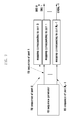
- FIG. 4 illustrates a method for generating a DRS according to an embodiment of the present invention. As shown in FIG. 4 , the method includes the following steps.
- step 401 an RS sequence of each antenna port is generated.
- an initialization parameter for generating the RS sequence is determined, an initialization value is calculated according to the initialization parameter, and the RS sequence of each antenna port is generated according to the initialization value.
- the above-mentioned initialization parameter may include an identity of the antenna port (port ID), an identity of a cell in which UE is located (cell ID), an identity of the UE (UE ID), and a time slot number of a time slot in which a DRS sequence is located.
- port ID an identity of the antenna port
- cell ID an identity of a cell in which UE is located
- UE ID an identity of the UE
- time slot number of a time slot in which a DRS sequence is located.
- the initialization parameter is a cell ID N ID cell , a time slot number n s and a UE ID n RNTI
- a RS sequence generator is initialized according to the initialization value c init
- the RS sequence of each antenna port is generated.
- initialization values are calculated according to initialization parameters, it should be ensured as much as possible that initialization values are different, and independent pseudo-random sequences are generated according to the different initialization values, i.e. RS sequences of all antennae ports are independent from each other, thereby avoiding an unbalanced transmission power of DRSs on OFDM symbols
- each RS sequence is spread and an spread RS sequence is obtained.
- each RS sequence is multiplied by a spreading code, which is preferably a Walsh code.
- the Walsh code may be hopped in the RS sequence corresponding to each antenna port. Multiple antenna ports in the same cell obtains RS sequences by cyclic shift of the same Walsh code hopping sequence, so as to implement the orthogonal interaction of DRS sequences of data streams in the cell. Different cells adopt different hopping patterns, so as to implement interference balance.
- Each group of DRSs using the CDM mode may repeatedly use the same Walsh hopping sequence or use different Walsh hopping sequences.
- the Walsh code may be changed by taking a Physical Resource Block (PRB) or the smallest CDM RE group as a unit.
- PRB Physical Resource Block
- the smallest RE group includes 2 REs
- the smallest RE group includes 4 REs.
- each antenna port fixedly adopts one Walsh code, but different cells adopt different mapping relations between Walsh codes and antenna ports.
- the mapping relations between Walsh codes and antenna ports may be determined by a cell ID, a time slot number and an index of a CDM RE group, e.g.
- the transmission modes adopted by the UE include a single-cell transmission mode not adopting MU-MIMO, a CoMP transmission mode not adopting MU-MIMO, an implicit single-cell MU-MIMO transmission mode, a CoMP and implicit MU-MIMO transmission mode, an explicit single-cell MU-MIMO transmission mode, and a CoMP and explicit MU-MIMO transmission mode.
- the cell ID may be used as the initialization parameter, but the UE ID generally cannot be used as the initialization parameter, otherwise the UE cannot learn DRS sequences of other UEs performing MU-MIMO. This is because the UE generally does not learn IDs of other UEs performing the MU-MIMO and requires a large overhead to dynamically transmit this information.
- the cell ID cannot be used as the initialization parameter, because the UE will not learn DRS sequences of other UEs performing the MU-MIMO. This is because the UE generally does not learn cell IDs of cells in which other UEs performing the MU-MIMO are located, and the UE requires a large overhead to transmit this information.
- each spread RS sequence is multiplied by a predefined scrambling code and a desired DRS sequence is obtained.
- an initialization parameter for generating the scrambling code is determined, an initialization value is calculated according to the initialization parameter, the scrambling code is generated according to the initialization value, and each spread result is multiplied by the scrambling code, i.e. the spread RS sequence is scrambled.
- the length of the scrambling code is L RS ⁇ L w , where L RS represents the length of the RS sequence, and L w represents the length of the spreading code.
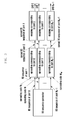
- all RS sequences may adopt the same scrambling code, i.e. each RS sequence is multiplied by a common scrambling code unrelated to an antenna port, as shown in FIG. 5 .
- FIG. 5 illustrates a method in which one scrambling code is used according to an embodiment of the present invention.
- the method is adapted to a DRS structure using a CDM mode and a DRS structure jointly using a CDM mode and other multiplexing modes.
- the method both can solve the problem of the imbalance of the power of OFDM symbols and can randomize the DRS interference between different cells.
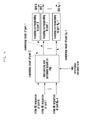
- the REs for transmitting DRSs are divided into N groups according to a Frequency Division Multiplexing (FDM) mode or a Time Division Multiplexing (TDM) mode, where N is generally equal to 2, and DRSs of multiple antenna ports are multiplexed by using a CDM mode in each CDM RE group.
- FDM Frequency Division Multiplexing
- TDM Time Division Multiplexing
- Two different scrambling codes can be used for RS sequences corresponding to antenna ports respectively belonging to two different CDM RE groups, so as to further randomize the DRS interference between cells, as shown in FIG. 6 .
- Figure 6 illustrates a method in which two scrambling code are used according to an embodiment of the present invention.
- the initialization parameter for generating the scrambling code may be the same as or different from the initialization parameter for generating the RS sequence in Step 401 of FIG. 4 .
- the initialization parameter for generating the RS sequence may be for example the port ID, the cell ID, the UE ID, or the time slot number
- the initialization parameter for generating the scrambling code may be the cell ID, the UE ID and the time slot number except the port ID.
- an index of a CDM RE group may also be used as the initialization parameter for generating the scrambling code.
- step 403 in FIG. 4 is optional. If step 403 is not performed, the interference balance between cells can be implemented by the hopping of the spreading code in step 402.
- a base station may use one bit of information to inform the UE whether this step is performed, and the one bit of information may be transmitted to the UE through a Packet Data Control CHannel (PDCCH) or through upper signalings.
- the one bit of information may also be bound with a transmission mode, e.g. step 403 is not performed in the CoMP and explicit MU-MIMO transmission mode and step 403 is performed in other transmission modes.
- the following embodiments can be used for a DRS structure using any one multiplexing mode, which includes a FDM mode, a TDM mode, a CDM mode and any combination thereof, and for any one method for generating the DRS, and is not limited to the method for generating the DRS provided by the present invention according to the DRS structure using the CDM mode or the DRS structure jointly using the CDM mode and other multiplexing modes.
- the initialization parameter usually refers to an initialization parameter for generating the RS sequence.
- the initialization parameter also refers to an initialization parameter for generating the RS sequence.
- the rule for determining the initialization parameter is adapted to both the method for generating the RS sequence and the method for generating the scrambling code.
- the port ID, the cell ID, the UE ID and the time slot number can be used as the initialization parameter.
- the port ID, the cell ID, the UE ID and the time slot number can be used as the initialization parameter.
- the UE In the two explicit MU-MIMO transmission modes, the UE needs to learn DRSs of other UEs performing MU-MIMO, so as to restrain the interference of other UEs on the UE. In the two transmission modes, the selection of the initialization parameter will be somewhat limited.
- the UE ID In the explicit single-cell MU-MIMO transmission mode, the UE ID generally is not used as the initialization parameter, since the UE generally does not learn IDs of other UEs performing MU-MIMO and require s a large overhead to dynamically transmit this information. Other information except the UE ID can be used as the initialization parameter.
- the cell ID is not used as the initialization parameter, since one base station may simultaneously transmit data in one PRB to multiple UE belonging to multiple cells, but the UE generally does not learn cell IDs of cells in which other UEs performing MU-MIMO is located and requires a large overhead to transmit this information.
- Other information except the UE ID and the cell ID can be used as the initialization parameter.
- a CoMP region ID can be defined, and is used as the initialization parameter.
- the definition of the CoMP region ID is well known in the art and will be omitted herein for conciseness.
- a System Frame Number may also be used as the initialization parameter, so as to further randomize the DRS interference.
- the UE In the explicit single-cell MU-MIMO transmission mode and the CoMP and explicit MU-MIMO transmission mode, in order to improve the receiving performance of MU-MIMO, the UE needs to learn DRS information of other UEss performing MU-MIMO. Specifically, if downlink resources are allocated by taking a PRB as a unit, the UE needs to learn DRS sequences used for other MU-MIMO UEs on each PRB allocated to the UE by the base station, so as to evaluate equivalent channels of other UEss and remove interference.
- the present invention points out that an index of the PRB allocated to the UE by the base station needs to be used when the DRS sequence of the UE is generated.
- the index of the PRB can be directly used for generating the DRS sequence, or a value transformed from the index of the PRB is used for generating the DRS sequence.
- a transforming principle is to guarantee that the same value is obtained after indexes of PRBs with the same frequency location are transformed.
- downlink bandwidth of multiple cells performing CoMP transmission may be different, so the indexes of PRBs with the same frequency location in two cells may be different, but it is ensured that the same value is obtained after the indexes of the PRBs with the same frequency location are transformed, thereby ensuring that the UE can learn the DRS sequences used by other UEs performing MU-MIMO.
- FIG. 7 illustrates a process for generating an RS sequence for a PRB according to an embodiment of the present invention.
- the RS sequence is generated for each PRB allocated to UE by a base station.
- An index of the PRB allocated to the UE by the base station or a value transformed from the index of the PRB is used as an initialization parameter for generating the RS sequence.
- other initialization parameters may also be used, e.g. a port ID and a time slot number.
- RS sequences corresponding to all PRBs are combined and a desired DRS sequence is obtained.
- initialization values are calculated according to initialization parameters, it should be ensured as much as possible that initialization values are different, so as to generate independent pseudo-random sequences according to the different initialization values, i.e. make RS sequences of all antenna ports are independent from each other.
- the combining operation mentioned here may be performed before the spreading operation, i.e. the spreading operation is performed after the RS sequences are generated for the PRBs and are combined.
- the combining operation may be performed after the spreading operation, i.e. the combining operation is performed after the RS sequences are generated for the PRBs and are spread.
- the combining operation mentioned here may be performed after the scrambling operation, i.e. the RS sequences are generated for the PRBs, a scrambling code is generated for the PRBs, and the RS sequences are spread, scrambled and combined.
- Figure 8 illustrates an intercepting process according to an embodiment of the present invention.
- an initial DRS sequence first is generated for each antenna port, then the initial DRS sequence is intercepted according to indexes of PRBs allocated to the UE by the base station or according to values transformed from the indexes of the PRBs, to obtain DRS sequence segments.
- the DRS sequence segments are combined according to the indexes of the PRBs allocated to the UE by the base station or according to the values transformed from the indexes of the PRBs, to obtain the desired DRS sequence.
- DRS sequence segments corresponding to one PRB may include several continuous elements in the initial DRS sequence.
- the combining operation is a single concatenation operation, or the DRS sequence segments corresponding to one PRB may also include several discontinuous elements in the initial DRS sequence, The discontinuous elements need be intercepted and combined respectively.
- the intercepting operation is performed according to an index of a PRB in the first time slot of each subframe or a value transformed from the index of the PRB, or the intercepting operation is performed according to an index of a PRB in each time slot of each subframe or a value transformed from the index of the PRB.
- the second above-described intercepting mode is adopted.
- the intercepting operation and the combining operation mentioned here may be performed before the spreading operation, i.e. the spreading operation is performed after the RS sequences are generated and combined.
- the intercepting operation and the combining operation may be performed after the spreading operation, i.e. the intercepting operation and the combining operation are performed after the RS sequences are generated and spread.
- the scrambling operation is performed, the intercepting operation and the combining operation mentioned here may be performed after the scrambling operation, i.e. the intercepting operation and the combining operation are performed after the RS sequences and the scrambling code are generated and the RS sequences are spread and scrambled.
- the second mode is described by the following examples.
- Indexes of elements in a DRS sequence obtained by intersecting and concatenating in the initial DRS sequence are ⁇ k 0 L , k 0 L +1,..., k 0 L+L -1, k 1 L , k 1 L +1,... k 1 L+L -1,... k N -1 L , k N -1 L +1,... k N -1 L + L -1 ⁇ .
- DRS sequence segments of one PRB are mapped to two locations in the initial DRS sequence.
- the length of the DRS sequence in each PRB is 2 L and system bandwidth is N RB
- one DRS sequence is generated, the length of the DRS sequence is equal to the length of a DRS sequence in one PRB, and the generated DRS sequence is unrelated to an index of a PRB allocated to the UE.
- the generated DRS sequence is taken as a DRS sequence corresponding to each PRB allocated to the UE by the base station, DRS sequences corresponding to all PRBs are combined, and the desired DRS sequence is obtained.
- the combining operation mentioned here may be performed before the spreading operation, i.e. the spreading operation is performed after the RS sequences are generated for one PRB and are used to PRBs allocated by the base station.
- the combining operation may be performed after the spreading operation, i.e. the spreading operation is performed after the RS sequences are generated for one PRB, are spread and are used to PRBs allocated by the base station.
- the combining operation mentioned here may be performed after the scrambling operation, i.e. the combining operation is performed after the RS sequences and the scrambling code are generated for one PRB and the RS sequences are spread, scrambled and are used to PRBs allocated by the base station.
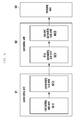
- FIG. 9 illustrates an apparatus for generating a DRS according to an embodiment of the present invention.
- the apparatus includes a generating unit 91, a spreading unit 92, and a mapping unit 93.
- the generating unit 91 is adapted to generate an RS sequence of each antenna port; and the spreading unit 92 is adapted to spread each RS sequence, obtain an spread RS sequence, multiply each spread RS sequence by a predefined scrambling code, and obtain a desired DRS sequence.
- the mapping unit 93 is adapted to perform RE mapping for each DRS sequence.
- the generating unit 91 includes a calculating sub-unit 911, adapted to determine an initialization parameter for generating the RS sequence, and calculate an initialization value according to the initialization parameter, and a generating sub-unit 912, adapted to generate the RS sequence of each antenna port according to the initialization value.
- the spreading unit 92 includes a first spreading sub-unit 921, adapted to multiply each RS sequence by an spreading code, and perform hopping of each antenna port using a predefined spreading code, and a second spreading sub-unit 922, adapted to determine an initialization parameter for generating the scrambling code, calculate an initialization value according to the initialization parameter, generate a common scrambling code unrelated to the antenna port according to the initialization value, and multiply each spread RS sequence by the common scrambling code.
- the second spreading sub-unit 922 is adapted to determine an initialization parameter for generating the scrambling code, calculate an initialization value according to the initialization parameter, generate N scrambling codes according to the initialization value, and multiply each spread RS sequence by a scrambling code corresponding the spread RS sequence, where N is a positive integer and is equal to the number of CDM RE groups for transmitting the DRS.
- the present invention solves the problem of the imbalance of the power of OFDM symbols, and also randomizes DRS interference between different cells.
- the present invention optimizes the performance of MU-MIMO, and allows the UE to learn DRS sequence information of other UEs performing MU-MIMO, thereby supporting an explicit MU-MIMO transmission mode.
Landscapes
- Engineering & Computer Science (AREA)
- Signal Processing (AREA)
- Computer Networks & Wireless Communication (AREA)
- Mobile Radio Communication Systems (AREA)
Abstract
Description
- This application claims priority to an application filed in the Chinese Patent Office on June 19, 2009 and assigned Serial No.
200910146321.1 - The present invention relates generally to radio communication technologies, and more particularly, to a method and apparatus for generating a Dedicated Reference Signal (DRS) in a radio communication system.
- In an Advanced Long Term Evolution (LTE-A) system, 8 transmitting antennae are configured for each cell to support a higher peak rate. In order to decrease the overhead of Reference Signals (RS), a DRS is used to demodulate downlink data. A base station sends a DRS for each stream of data of each User Equipment (UE). Most UEs in a cell adopt a low rank transmission mode, wherein the value of the rank is equal to the number of streams simultaneously transmitted by the UE. As such, the number of DRSs actually transmitted by each UE is small, thereby decreasing the overhead of reference signals. In addition, the use of the DRS is convenient for Coordinated Multi-Point (CoMP) transmission and Multi-User Multiple-Input Multiple-Output (MU-MIMO) transmission.
- In the LTE-A system, the CoMP transmission is mainly used for improving the average throughput of a cell and the throughput of a cell boundary, and includes two specific implementation modes, i.e. coordinated scheduling and coordinated multi-point joint transmission. For the coordinated scheduling, data of one UE only comes from one transmitting node, i.e. one serving cell. Data transmitted by other nodes is received as interference, and thus multiple nodes need coordinated scheduling to control an interference level. For the coordinated multi-point joint transmission, multiple nodes may transmit data to one UE by using the same time-frequency resources, thereby increasing the signal-to-noise ratio of the UE and decreasing the interference. Based on a DRS, the LTE-A system may support transparent coordinated multi-point joint transmission. The UE only receives data of a Physical Downlink Control CHannel (PDCCH) transmitted by one node, and the node is a serving cell of the UE. At the same time, data transmission is based on the DRS, and the UE receives the DRS, performs channel evaluation and demodulates the data, but does not consider which nodes transmit the data.
- In addition, since MU-MIMO is adopted in the LTE-A system, data of multiple UEs can be transmitted by using the same time-frequency resources. The MU-MIMO has also been supported in a Long Term Evolution (LTE) system. However, MU-MIMO in the LTE solution is defined based on Single-User MIMO (SU-MIMO), which limits performance gain. In the LTE-A system, the MU-MIMO is to be optimized, by providing scheduling information of other UEs performing MU-MIMO with one UE, so that the UE can report more accurate Channel Quality Indicator (CQI) information, and remove interference as much as possible when demodulating data. For MU-MIMO based on a DRS, a base station is configured such that multiple UE performing MU-MIMO adopt different DRS patterns that preferably are orthogonal, to obtain a better channel evaluation performance.
-
FIG. 1 illustrates a conventional DRS structure. A Code Division Multiplexing (CDM) and Frequency Division Multiplexing (FDM) mode is adopted, i.e. the Resource Elements (RE) for transmitting DRSs are divided into two groups by using a FDM mode, and DRSs of multiple data streams are multiplexed in each RE group by using a CDM mode. Hereinafter, each group of REs will be referred to as a CDM RE group. -
FIG. 2 illustrates a conventional method for generating and mapping a DRS. As shown inFIG. 2 , an RS sequence of each antenna port, i.e. a DRS sequence, is generated, and then RE mapping is performed for the RS sequence. There are three methods for generating the RS sequence. In the first method, one random sequence is generated for each antenna port by using different initialization values, and then the RS sequence is generated according to the random sequence. In the second method, one random sequence is generated by using one initialization value, one long scrambling sequence is generated according to the random sequence, and the long scrambling sequence is divided into multiple subsections and the RS sequence of each antenna port is obtained. In the third method, one random sequence is generated by using one initialization value, then one scrambling code sequence is generated according to the random sequence, and each antenna port uses the scrambling code sequence as the RS sequence. - For a DRS structure using the CDM mode or a DRS structure jointly using the CDM mode and other multiplexing modes, the step of generating the RS sequence shown in
FIG. 2 can be described in detail, e.g. a method for generating and mapping a DRS shown inFIG. 3 . As shown inFIG. 3 , an RS sequence of each antenna port is generated, then each element of each RS sequence is spread to obtain an spread RS sequence, where an spreading code may be a Walsh code, and RE mapping is performed for the spread RS sequence. - For the method shown in
FIG. 3 , if RS sequences of all antenna ports are identical, when DRSs of multiple data streams are transmitted by using the CDM mode, it is possible for DRSs on one OFDM symbol to adopt double transmission power and DRSs on the other OFDM symbol to have no transmission power, thereby influencing total power for data transmission. If the RS sequences of all antenna ports are independent from each other, an imbalance of transmission power of DRSs is not a problem. However, the method shown inFIG. 3 cannot restrain DRS interference between different cells. Generally, the smaller the interference, the better the performance, but the method shown inFIG. 3 results in the interference fixedly coming from a certain cell or UE. - In view of the above, an object of the present invention is to provide a method and apparatus for generating a DRS, which can randomize DRS interference between different cells.
- In order to achieve the above objects, a method for generating a DRS includes generating an RS sequence of each antenna port, spreading each RS sequence and obtaining an spread RS sequence, and multiplying each spread RS sequence by a predefined scrambling code and obtaining a desired DRS sequence.
- Generating the RS sequence of each antenna port includes determining an initialization parameter for generating the RS sequence, calculating an initialization value according to the initialization parameter, and generating the RS sequence of each antenna port according to the initialization value.
- Multiplying each spread RS sequence by a predefined scrambling code includes determining an initialization parameter for generating the scrambling code, calculating an initialization value according to the initialization parameter, generating a common scrambling code unrelated to the antenna port, multiplying each spread RS sequence by the common scrambling code, and determining an initialization parameter for generating the scrambling code, calculating an initialization value according to the initialization parameter, generating N scrambling codes according to the initialization value, and multiplying each spread RS sequence by a scrambling code corresponding to the spread RS sequence, where N is a positive integer and is equal to the number of Code Division Multiplexing Resource Element (CDM RE) groups for transmitting the DRS.
- The initialization value for generating the RS sequence is the same as or is different from the initialization value for generating the scrambling code.
- When the UE does not adopt a MU-MIMO transmission mode, or adopts an implicit MU-MIMO transmission mode, an identity of the antenna port (port IDentifier (ID)), an identity of a cell in which the UE is located (cell ID), an identity of the UE (UE ID), and/or a time slot number of a time slot in which the DRS sequence is located are used as the initialization parameter.
- When the UE adopts an explicit single-cell MU-MIMO transmission mode, the port ID, the cell ID, and/or the time slot number are used as the initialization parameter. When the UE adopts a Coordinated Multi-Point (CoMP) transmission mode and the explicit MU-MIMO transmission mode, the port ID, the time slot number, a predefined CoMP region ID, and/or a system frame number are used as the initialization parameter.
- The port ID is used as the initialization parameter for generating the RS sequence, and indexes of the CDM RE groups are further used as the initialization parameter in a mode for generating the N scrambling codes.
- Spreading each RS sequence includes multiplying each RS sequence by a spreading code, and using a predefined spreading code by hopping of each antenna port. Using a predefined spreading code by hopping of each antenna port includes changing the spreading code by taking a Physical Resource Block (PRB) as a unit, or changing the spreading code by taking a smallest CDM RE group as a unit.
- The method further includes generating, for each antenna port, respective DRS sequences for all PRBs allocated to the UE, using indexes of the PRBs or values transformed from the indexes of the PRBs as initialization parameters for generating the RS sequence, combining the DRS sequences respectively corresponding to the PRBs, and obtaining the desired DRS sequence.
- Also included is generating, for each antenna port, an initial DRS sequence, intercepting segments from the initial DRS sequence according to indexes of all PRBs allocated to UE or values transformed from the indexes of the PRBs, combining the intercepted segments, and obtaining the desired DRS sequence.
- Further included is generating a DRS sequence for each antenna port, the length of the generated DRS sequence being equal to the length of a DRS sequence in a PRB, and the generated DRS sequence is unrelated to all PRBs allocated to UE, and using the generated DRS sequence as DRS sequences respectively corresponding to the PRBs, combining the DRS sequences respectively corresponding to the PRBs, and obtaining the desired DRS sequence.
- The segments are intercepted according to an index of a PRB in each time slot of each subframe or according to a value transformed from the index of the PRB.
- An apparatus for generating a DRS includes a generating unit, adapted to generate an RS sequence of each antenna port, and a spreading unit, adapted to spread each RS sequence, obtain a spread RS sequence, multiply each spread RS sequence by a predefined scrambling code, and obtain a desired DRS sequence.
- The generating unit includes a calculating sub-unit, adapted to determine an initialization parameter for generating the RS sequence, and to calculate an initialization value according to the initialization parameter, and a generating sub-unit, adapted to generate the RS sequence of each antenna port according to the initialization value.
- The spreading unit includes a first spreading sub-unit, adapted to multiply each RS sequence by a spreading code, and perform hopping of each antenna port using a predefined spreading code, and a second spreading sub-unit, adapted to determine an initialization parameter for generating the scrambling code, calculate an initialization value according to the initialization parameter, generate a common scrambling code unrelated to the antenna port according to the initialization value, and multiply each spread RS sequence by the common scrambling code.
- The spreading unit further includes a first spreading sub-unit, adapted to multiply each RS sequence by an spreading code, and to perform hopping of each antenna port using a predefined spreading code, and a second spreading sub-unit, adapted to determine an initialization parameter for generating the scrambling code, calculate an initialization value according to the initialization parameter, generate N scrambling codes according to the initialization value, and multiply each spread RS sequence by a scrambling code corresponding the spread RS sequence, where N is a positive integer and is equal to the number of CDM RE) groups for transmitting the DRS.
- The apparatus further includes a mapping unit, adapted to perform RE mapping for each desired DRS sequence.
- Accordingly, in the present invention, after the spread RS sequence is obtained, the spread RS sequence is multiplied by a predefined scrambling code, a specific format of the scrambling code can be configured according to requirements, and thus not only the problem that the power of OFDM symbols is unbalanced can be solved, but also, DRS interference between different cells can be randomized. In addition, the present invention optimizes the performance of MU-MIMO, and allows the UE to learn DRS sequence information of other UEs performing MU-MIMO, thereby supporting an explicit MU-MIMO transmission mode.
-
-
Figure 1 illustrates a conventional DRS structure. -
Figure 2 illustrates a conventional method for generating and mapping a DRS. -
Figure 3 illustrates another method for generating and mapping a DRS in the prior art. -
Figure 4 illustrates a method for generating a DRS according to an embodiment of the present invention. -
Figure 5 illustrates an implementation in which one scrambling code is used according to an embodiment of the present invention. -
Figure 6 illustrates an implementation in which two scrambling code are used according to an embodiment of the present invention. -
Figure 7 illustrates a process for generating an RS sequence for a PRB according to an embodiment of the present invention. -
Figure 8 illustrates an intercepting process according to an embodiment of the present invention. -
Figure 9 illustrates the structure of an apparatus for generating a DRS according to an embodiment of the present invention. - Hereinafter, embodiments of the present invention are described in detail with reference to the accompanying drawings. The same reference numbers are used throughout the drawings to refer to the same or similar parts. Detailed descriptions of well-known functions and structures incorporated herein may be omitted for the sake of clarity and conciseness.
- In order to solve the problems occuring in the prior art, the present invention provides a new method for generating and mapping a DRS, which includes generating a RS sequence of each antenna port, spreading each RS sequence and obtaining an spread RS sequence, multiplying each spread RS sequence by a predefined scrambling code and obtaining a desired DRS sequence, and performing RE mapping for each DRS sequence.
- For a DRS structure using a CDM mode or a DRS structure jointly using a CDM mode and other multiplexing modes such as a FDM mode,
FIG. 4 illustrates a method for generating a DRS according to an embodiment of the present invention. As shown inFIG. 4 , the method includes the following steps. - In
step 401, an RS sequence of each antenna port is generated. In this step, an initialization parameter for generating the RS sequence is determined, an initialization value is calculated according to the initialization parameter, and the RS sequence of each antenna port is generated according to the initialization value. - The above-mentioned initialization parameter may include an identity of the antenna port (port ID), an identity of a cell in which UE is located (cell ID), an identity of the UE (UE ID), and a time slot number of a time slot in which a DRS sequence is located. A specific method for generating the DRS is described by an example. Suppose the initialization parameter is a cell ID


- In
step 402, each RS sequence is spread and an spread RS sequence is obtained. In this step, each RS sequence is multiplied by a spreading code, which is preferably a Walsh code. In order to randomize DRS interference between adjacent cells, the Walsh code may be hopped in the RS sequence corresponding to each antenna port. Multiple antenna ports in the same cell obtains RS sequences by cyclic shift of the same Walsh code hopping sequence, so as to implement the orthogonal interaction of DRS sequences of data streams in the cell. Different cells adopt different hopping patterns, so as to implement interference balance. Each group of DRSs using the CDM mode may repeatedly use the same Walsh hopping sequence or use different Walsh hopping sequences. - When a hopping sequence is defined, the Walsh code may be changed by taking a Physical Resource Block (PRB) or the smallest CDM RE group as a unit. When a Walsh code with the length of 2 is adopted, the smallest RE group includes 2 REs, and when a Walsh code with the length of 4 is adopted, the smallest RE group includes 4 REs. As an example of hopping, each antenna port fixedly adopts one Walsh code, but different cells adopt different mapping relations between Walsh codes and antenna ports. The mapping relations between Walsh codes and antenna ports may be determined by a cell ID, a time slot number and an index of a CDM RE group, e.g. mod(cell_ID+p,Lw ) or mod(cell_ID + g + p,Lw ), where p is an index of an antenna port, g is an index of a CDM RE group and Lw is the length of a Walsh code.
- In addition, according to the difference of transmission modes adopted by the UE, initialization parameters adopted when the spreading code is generated are different. Herein, the transmission modes adopted by the UE include a single-cell transmission mode not adopting MU-MIMO, a CoMP transmission mode not adopting MU-MIMO, an implicit single-cell MU-MIMO transmission mode, a CoMP and implicit MU-MIMO transmission mode, an explicit single-cell MU-MIMO transmission mode, and a CoMP and explicit MU-MIMO transmission mode.
- In the two transmission modes not adopting MU-MIMO, since different cells need to adopt different Walsh hopping patterns to randomize DRS interference, the cell ID may be used as the initialization parameter, but the UE ID generally cannot be used as the initialization parameter, otherwise the UE cannot learn DRS sequences of other UEs performing MU-MIMO. This is because the UE generally does not learn IDs of other UEs performing the MU-MIMO and requires a large overhead to dynamically transmit this information. In the CoMP and explicit MU-MIMO transmission mode, the cell ID cannot be used as the initialization parameter, because the UE will not learn DRS sequences of other UEs performing the MU-MIMO. This is because the UE generally does not learn cell IDs of cells in which other UEs performing the MU-MIMO are located, and the UE requires a large overhead to transmit this information.
- In
step 403, each spread RS sequence is multiplied by a predefined scrambling code and a desired DRS sequence is obtained. - In this step, an initialization parameter for generating the scrambling code is determined, an initialization value is calculated according to the initialization parameter, the scrambling code is generated according to the initialization value, and each spread result is multiplied by the scrambling code, i.e. the spread RS sequence is scrambled. The length of the scrambling code is LRS × Lw, where LRS represents the length of the RS sequence, and Lw represents the length of the spreading code. When the initialization values are calculated according to initialization parameters, it should be ensured as much as possible that initialization values are different, so as to generate independent pseudo-random sequences according to the different initialization values.
- In practical applications, all RS sequences may adopt the same scrambling code, i.e. each RS sequence is multiplied by a common scrambling code unrelated to an antenna port, as shown in
FIG. 5 . -
FIG. 5 illustrates a method in which one scrambling code is used according to an embodiment of the present invention. The method is adapted to a DRS structure using a CDM mode and a DRS structure jointly using a CDM mode and other multiplexing modes. The method both can solve the problem of the imbalance of the power of OFDM symbols and can randomize the DRS interference between different cells. - Suppose the REs for transmitting DRSs are divided into N groups according to a Frequency Division Multiplexing (FDM) mode or a Time Division Multiplexing (TDM) mode, where N is generally equal to 2, and DRSs of multiple antenna ports are multiplexed by using a CDM mode in each CDM RE group. Two different scrambling codes can be used for RS sequences corresponding to antenna ports respectively belonging to two different CDM RE groups, so as to further randomize the DRS interference between cells, as shown in
FIG. 6 . -
Figure 6 illustrates a method in which two scrambling code are used according to an embodiment of the present invention. - In practical applications, the initialization parameter for generating the scrambling code may be the same as or different from the initialization parameter for generating the RS sequence in
Step 401 ofFIG. 4 . Generally, the initialization parameter for generating the RS sequence may be for example the port ID, the cell ID, the UE ID, or the time slot number, and the initialization parameter for generating the scrambling code may be the cell ID, the UE ID and the time slot number except the port ID. In addition, in the method shown inFIG. 6 , an index of a CDM RE group may also be used as the initialization parameter for generating the scrambling code. - It is noted that
step 403 inFIG. 4 is optional. Ifstep 403 is not performed, the interference balance between cells can be implemented by the hopping of the spreading code instep 402. A base station may use one bit of information to inform the UE whether this step is performed, and the one bit of information may be transmitted to the UE through a Packet Data Control CHannel (PDCCH) or through upper signalings. In addition, the one bit of information may also be bound with a transmission mode,e.g. step 403 is not performed in the CoMP and explicit MU-MIMO transmission mode and step 403 is performed in other transmission modes. - In practical applications, according to different transmission modes used by the UE, different information will be used as the initialization parameter.
- It is noted that the following embodiments can be used for a DRS structure using any one multiplexing mode, which includes a FDM mode, a TDM mode, a CDM mode and any combination thereof, and for any one method for generating the DRS, and is not limited to the method for generating the DRS provided by the present invention according to the DRS structure using the CDM mode or the DRS structure jointly using the CDM mode and other multiplexing modes. In the method shown in
FIG. 2 , the initialization parameter usually refers to an initialization parameter for generating the RS sequence. In the method shown inFIG. 3 , the initialization parameter also refers to an initialization parameter for generating the RS sequence. In the method shown inFIG. 4 , the rule for determining the initialization parameter is adapted to both the method for generating the RS sequence and the method for generating the scrambling code. - In the single-cell transmission mode not adopting MU-MIMO and the CoMP transmission mode not adopting MU-MIMO, the port ID, the cell ID, the UE ID and the time slot number can be used as the initialization parameter.
- In the implicit single-cell MU-MIMO transmission mode and the CoMP and implicit MU-MIMO transmission mode, the port ID, the cell ID, the UE ID and the time slot number can be used as the initialization parameter.
- In the two explicit MU-MIMO transmission modes, the UE needs to learn DRSs of other UEs performing MU-MIMO, so as to restrain the interference of other UEs on the UE. In the two transmission modes, the selection of the initialization parameter will be somewhat limited.
- In the explicit single-cell MU-MIMO transmission mode, the UE ID generally is not used as the initialization parameter, since the UE generally does not learn IDs of other UEs performing MU-MIMO and require s a large overhead to dynamically transmit this information. Other information except the UE ID can be used as the initialization parameter.
- In the CoMP and explicit MU-MIMO transmission mode, besides the UE ID, the cell ID is not used as the initialization parameter, since one base station may simultaneously transmit data in one PRB to multiple UE belonging to multiple cells, but the UE generally does not learn cell IDs of cells in which other UEs performing MU-MIMO is located and requires a large overhead to transmit this information. Other information except the UE ID and the cell ID can be used as the initialization parameter.
- In the CoMP and explicit MU-MIMO transmission mode, in order to improve the performance of the randomization of the DRS interference between cells, a CoMP region ID can be defined, and is used as the initialization parameter. The definition of the CoMP region ID is well known in the art and will be omitted herein for conciseness. In addition, a System Frame Number (SFN) may also be used as the initialization parameter, so as to further randomize the DRS interference.
- In the explicit single-cell MU-MIMO transmission mode and the CoMP and explicit MU-MIMO transmission mode, in order to improve the receiving performance of MU-MIMO, the UE needs to learn DRS information of other UEss performing MU-MIMO. Specifically, if downlink resources are allocated by taking a PRB as a unit, the UE needs to learn DRS sequences used for other MU-MIMO UEs on each PRB allocated to the UE by the base station, so as to evaluate equivalent channels of other UEss and remove interference.
- Since PRBs allocated to two or more UEs performing MU-MIMO may be partly overlapped, in order to guarantee that the UE can learn the DRS sequences used by other UEs performing MU-MIMO when the RS sequence is generated, the present invention points out that an index of the PRB allocated to the UE by the base station needs to be used when the DRS sequence of the UE is generated. Here, the index of the PRB can be directly used for generating the DRS sequence, or a value transformed from the index of the PRB is used for generating the DRS sequence. Herein, a transforming principle is to guarantee that the same value is obtained after indexes of PRBs with the same frequency location are transformed. For example, in the CoMP and explicit MU-MIMO transmission mode, downlink bandwidth of multiple cells performing CoMP transmission may be different, so the indexes of PRBs with the same frequency location in two cells may be different, but it is ensured that the same value is obtained after the indexes of the PRBs with the same frequency location are transformed, thereby ensuring that the UE can learn the DRS sequences used by other UEs performing MU-MIMO.
- The following processing modes can be used to implement the present invention.
-
FIG. 7 illustrates a process for generating an RS sequence for a PRB according to an embodiment of the present invention. As shown inFIG. 7 , for each antenna port, the RS sequence is generated for each PRB allocated to UE by a base station. An index of the PRB allocated to the UE by the base station or a value transformed from the index of the PRB is used as an initialization parameter for generating the RS sequence. Based on this, other initialization parameters may also be used, e.g. a port ID and a time slot number. For each antenna port, RS sequences corresponding to all PRBs are combined and a desired DRS sequence is obtained. - For example, suppose the index of the PRB allocated to the UE by the base station is k, and other initialization parameters for generating the RS sequence include a cell ID


- It should be noted that the method for calculating the initialization value is shown by way of example, and is not used to limit the technical solution of the present invention.
- In addition, when initialization values are calculated according to initialization parameters, it should be ensured as much as possible that initialization values are different, so as to generate independent pseudo-random sequences according to the different initialization values, i.e. make RS sequences of all antenna ports are independent from each other.
- Specially, for a DRS structure using a CDM mode or a DRS structure jointly using a CDM mode and other multiplexing modes, in the method as shown in
FIG. 4 , if no scrambling operation is performed, the combining operation mentioned here may be performed before the spreading operation, i.e. the spreading operation is performed after the RS sequences are generated for the PRBs and are combined. Alternatively, the combining operation may be performed after the spreading operation, i.e. the combining operation is performed after the RS sequences are generated for the PRBs and are spread. If the scrambling operation is performed, the combining operation mentioned here may be performed after the scrambling operation, i.e. the RS sequences are generated for the PRBs, a scrambling code is generated for the PRBs, and the RS sequences are spread, scrambled and combined. -
Figure 8 illustrates an intercepting process according to an embodiment of the present invention. As shown inFIG. 8 , , an initial DRS sequence first is generated for each antenna port, then the initial DRS sequence is intercepted according to indexes of PRBs allocated to the UE by the base station or according to values transformed from the indexes of the PRBs, to obtain DRS sequence segments. The DRS sequence segments are combined according to the indexes of the PRBs allocated to the UE by the base station or according to the values transformed from the indexes of the PRBs, to obtain the desired DRS sequence. - According to a specific arrangement structure of each element in the initial DRS sequence, DRS sequence segments corresponding to one PRB may include several continuous elements in the initial DRS sequence. The combining operation is a single concatenation operation, or the DRS sequence segments corresponding to one PRB may also include several discontinuous elements in the initial DRS sequence, The discontinuous elements need be intercepted and combined respectively. For the UE adopting time slot hopping frequency in a Physical Downlink Sharing CHannel (PDSCH), the intercepting operation is performed according to an index of a PRB in the first time slot of each subframe or a value transformed from the index of the PRB, or the intercepting operation is performed according to an index of a PRB in each time slot of each subframe or a value transformed from the index of the PRB. Generally, when local PDSCH and hopping frequency PDSCH are multiplexed, the second above-described intercepting mode is adopted.
- Similarly, for the DRS structure using a CDM mode or the DRS structure jointly using a CDM mode and other multiplexing modes, in the method shown in
FIG. 4 if no scrambling operation is performed, the intercepting operation and the combining operation mentioned here may be performed before the spreading operation, i.e. the spreading operation is performed after the RS sequences are generated and combined. Alternatively, the intercepting operation and the combining operation may be performed after the spreading operation, i.e. the intercepting operation and the combining operation are performed after the RS sequences are generated and spread. If the scrambling operation is performed, the intercepting operation and the combining operation mentioned here may be performed after the scrambling operation, i.e. the intercepting operation and the combining operation are performed after the RS sequences and the scrambling code are generated and the RS sequences are spread and scrambled. - The second mode is described by the following examples.
- Suppose the length of the DRS sequence in each PRB is L and corresponds to L continuous elements in the initial DRS sequence, and system bandwidth is NRB , an initial DRS sequence with the length of L· NRB is generated, where indexes of the elements are respectively n = 0,1 .... L · NRB - 1. Suppose an index set of PRBs allocated to one UE by a base station is K = {k0 ,k1 ,...,kN-1 ,}, where N is the number of the PRBs allocated to the UE by the base station. Indexes of elements in a DRS sequence obtained by intersecting and concatenating in the initial DRS sequence are {k 0 L,k 0 L+1,...,k 0 L+L-1,k 1 L,k 1 L+1,...k 1 L+L-1,...k N-1 L,k N-1 L+1,...k N-1 L+L-1}.
- For the DRS multiplexing structure as shown in
FIG. 1 , suppose the first half of elements in the initial DRS sequence are mapped to the first two columns DRS REs in each PRB to be transmitted, and the second half of elements in the initial DRS sequence are mapped to the last two columns DRS REs in each PRB to be transmitted, i.e. DRS sequence segments of one PRB are mapped to two locations in the initial DRS sequence. Suppose the length of the DRS sequence in each PRB is 2L and system bandwidth is NRB, an initial DRS sequence with the length of 2L · NRB is generated, where indexes of the elements are respectively n = 0,1,....2L · NRB -1. Suppose an index set of PRBs allocated to one piece of UE by a base station is K = {k 0,k 1,...,k N-1,}, where N is the number of the PRBs allocated to the UE by the base station, indexes of elements in a DRS sequence obtained by intersecting and combining in the initial DRS sequence are {k 0 L,k 0 L+1,...,k 0 L+L-1,k 1 L,k 1 L+1,...,k 1 L+L-1,...,k N-1 L,k N-1 L+1,...,k N-1 L+L-1} and L·NRB +{k 0 L,k 0 L+1,...,k 0 L+L-1,k 1 L,k 1 L+1,...,k 1 L+L-1,...,k N-1 L,k N-1 L+1,...k N-1 L+L-1} - For each antenna port, one DRS sequence is generated, the length of the DRS sequence is equal to the length of a DRS sequence in one PRB, and the generated DRS sequence is unrelated to an index of a PRB allocated to the UE. The generated DRS sequence is taken as a DRS sequence corresponding to each PRB allocated to the UE by the base station, DRS sequences corresponding to all PRBs are combined, and the desired DRS sequence is obtained.
- For the DRS structure using a CDM mode or the DRS structure jointly using a CDM mode and other multiplexing modes, in the method shown in
FIG. 4 , if no scrambling operation is performed, the combining operation mentioned here may be performed before the spreading operation, i.e. the spreading operation is performed after the RS sequences are generated for one PRB and are used to PRBs allocated by the base station. Alternatively, the combining operation may be performed after the spreading operation, i.e. the spreading operation is performed after the RS sequences are generated for one PRB, are spread and are used to PRBs allocated by the base station. If the scrambling operation is performed, the combining operation mentioned here may be performed after the scrambling operation, i.e. the combining operation is performed after the RS sequences and the scrambling code are generated for one PRB and the RS sequences are spread, scrambled and are used to PRBs allocated by the base station. -
FIG. 9 illustrates an apparatus for generating a DRS according to an embodiment of the present invention. As shown inFIG. 9 , the apparatus includes a generatingunit 91, a spreadingunit 92, and amapping unit 93. - The generating
unit 91 is adapted to generate an RS sequence of each antenna port; and the spreadingunit 92 is adapted to spread each RS sequence, obtain an spread RS sequence, multiply each spread RS sequence by a predefined scrambling code, and obtain a desired DRS sequence. Themapping unit 93 is adapted to perform RE mapping for each DRS sequence. - The generating
unit 91 includes a calculatingsub-unit 911, adapted to determine an initialization parameter for generating the RS sequence, and calculate an initialization value according to the initialization parameter, and a generating sub-unit 912, adapted to generate the RS sequence of each antenna port according to the initialization value. - The spreading
unit 92 includes a first spreadingsub-unit 921, adapted to multiply each RS sequence by an spreading code, and perform hopping of each antenna port using a predefined spreading code, and a second spreadingsub-unit 922, adapted to determine an initialization parameter for generating the scrambling code, calculate an initialization value according to the initialization parameter, generate a common scrambling code unrelated to the antenna port according to the initialization value, and multiply each spread RS sequence by the common scrambling code. Alternatively, the second spreadingsub-unit 922 is adapted to determine an initialization parameter for generating the scrambling code, calculate an initialization value according to the initialization parameter, generate N scrambling codes according to the initialization value, and multiply each spread RS sequence by a scrambling code corresponding the spread RS sequence, where N is a positive integer and is equal to the number of CDM RE groups for transmitting the DRS. - The specific order of components of the apparatus shown in
Figure 9 also refers to the description in the method shown inFIG. 4 , and will not be further described. - As described above, the present invention solves the problem of the imbalance of the power of OFDM symbols, and also randomizes DRS interference between different cells. In addition, the present invention optimizes the performance of MU-MIMO, and allows the UE to learn DRS sequence information of other UEs performing MU-MIMO, thereby supporting an explicit MU-MIMO transmission mode.
- Although embodiments of the present invention have been described in detail hereinabove, it should be understood that many variations and modifications of the basic inventive concept herein described, which may be apparent to those skilled in the art, will still fall within the spirit and scope of the embodiments of the present invention as defined in the appended claims.
Claims (6)
- A method for generating a Dedicated Reference Signal (DRS) in a radio communication system, comprising:generating an initial Reference Signal (RS) sequence; andobtaining the DRS sequence for a User Equipment (UE) from the initial RS sequence based on indexes of Physical Resource Blocks (PRBs) allocated to the UE.
- The method of Claim 1, wherein the pseudo random sequence generator of the initial RS sequence is initialized by a Cell IDentifier (ID) while a UE ID is excluded.
- The method of any one of Claims 1 - 2, wherein the initial DRS sequence is intercepted according to indexes of PRBs allocated to the UE to obtain DRS sequence segments, and the DRS sequence segments are combined according to the indexes of the PRBs allocated to the UE to obtain a desired DRS sequence.
- The method of any one of Claims 1 - 3, wherein the sequence segments related to one PRB index include continuous elements of the initial RS sequence.
- The method of any one of Claims 1 - 4, wherein the sequence segments related to one PRB index include discontinuous elements of the initial RS sequence.
- The method of any one of Claims 1 - 5, wherein the PRB indexes are the index of PRBs allocated to the UE in a slot.
Applications Claiming Priority (1)
| Application Number | Priority Date | Filing Date | Title |
|---|---|---|---|
| CN200910146321.1A CN101931485B (en) | 2009-06-19 | 2009-06-19 | Method and device for generating dedicated reference signal (DRS) |
Publications (3)
| Publication Number | Publication Date |
|---|---|
| EP2264937A2 true EP2264937A2 (en) | 2010-12-22 |
| EP2264937A3 EP2264937A3 (en) | 2017-01-18 |
| EP2264937B1 EP2264937B1 (en) | 2021-05-12 |
Family
ID=43034418
Family Applications (1)
| Application Number | Title | Priority Date | Filing Date |
|---|---|---|---|
| EP10166623.8A Active EP2264937B1 (en) | 2009-06-19 | 2010-06-21 | Method and apparatus for generating a dedicated reference signal |
Country Status (10)
| Country | Link |
|---|---|
| US (2) | US8755339B2 (en) |
| EP (1) | EP2264937B1 (en) |
| JP (2) | JP5976534B2 (en) |
| KR (1) | KR101691475B1 (en) |
| CN (1) | CN101931485B (en) |
| AU (1) | AU2010260669B2 (en) |
| CA (1) | CA2766045C (en) |
| HK (1) | HK1147862A1 (en) |
| RU (1) | RU2538773C2 (en) |
| WO (1) | WO2010147419A2 (en) |
Cited By (8)
| Publication number | Priority date | Publication date | Assignee | Title |
|---|---|---|---|---|
| WO2013069954A1 (en) | 2011-11-07 | 2013-05-16 | Pantech Co.,Ltd. | Apparatus and method for estimating channel |
| EP2487825A3 (en) * | 2011-01-28 | 2016-08-31 | Samsung Electronics Co., Ltd. | Method and device for generating reference signal in cellular mobile communication system |
| EP2695346A4 (en) * | 2011-07-15 | 2016-12-21 | Sun Patent Trust | Method of scrambling signals, transmission point device and user equipment using the method |
| WO2020076647A1 (en) * | 2018-10-10 | 2020-04-16 | At&T Intellectual Property I, L.P. | Mapping reference signals in wireless communication systems to avoid repetition |
| EP2467967B1 (en) * | 2009-08-17 | 2021-02-17 | Beijing Xiaomi Mobile Software Co., Ltd. | Apparatus and method for initialization and mapping of reference signals in a communication system |
| US11082279B2 (en) | 2018-09-27 | 2021-08-03 | At&T Intellectual Property I, L.P. | Facilitation of reduction of peak to average power ratio for 5G or other next generation network |
| US11418992B2 (en) | 2018-11-02 | 2022-08-16 | At&T Intellectual Property I, L.P. | Generation of demodulation reference signals in advanced networks |
| US11671947B2 (en) | 2011-07-15 | 2023-06-06 | Sun Patent Trust | Reception apparatus and reception method |
Families Citing this family (37)
| Publication number | Priority date | Publication date | Assignee | Title |
|---|---|---|---|---|
| US8948097B2 (en) | 2009-09-30 | 2015-02-03 | Qualcomm Incorporated | UE-RS sequence initialization for wireless communication systems |
| US8923905B2 (en) | 2009-09-30 | 2014-12-30 | Qualcomm Incorporated | Scrambling sequence initialization for coordinated multi-point transmissions |
| US9432164B2 (en) | 2009-10-15 | 2016-08-30 | Qualcomm Incorporated | Method and apparatus for reference signal sequence mapping in wireless communication |
| CN102594516A (en) * | 2011-01-07 | 2012-07-18 | 中兴通讯股份有限公司 | Method and system for processing reference signal of channel state information |
| TWI554046B (en) * | 2011-01-07 | 2016-10-11 | 內數位專利控股公司 | Method, system and apparatus for downlink shared channel reception in cooperative multipoint transmissions |
| CN102611486B (en) * | 2011-01-19 | 2018-03-16 | 中兴通讯股份有限公司 | A kind of Notification Method and system of scrambling code identification signaling group |
| EP2919545B1 (en) | 2011-02-11 | 2016-09-28 | Interdigital Patent Holdings, Inc. | Device and method for an enhanced control channel (e-pdcch) |
| US8849354B2 (en) * | 2011-02-25 | 2014-09-30 | Fujitsu Limited | Transceiver set assignment scheme for a distributed antenna system |
| WO2012132016A1 (en) * | 2011-03-31 | 2012-10-04 | 富士通株式会社 | Communications system, base station device, terminal device, and communications method |
| JP5793184B2 (en) * | 2011-04-26 | 2015-10-14 | パナソニック インテレクチュアル プロパティ コーポレーション オブアメリカPanasonic Intellectual Property Corporation of America | Transmitting device, receiving device, transmitting method, receiving method |
| WO2012149674A1 (en) * | 2011-05-03 | 2012-11-08 | Nokia Siemens Networks Oy | Methods and devices for dynamic allocation of identifiers in hybrid cell identifier scenarios |
| CN102811107B (en) | 2011-06-03 | 2016-03-30 | 华为技术有限公司 | Pilot frequency sequence collocation method and the network equipment |
| CN107104912B (en) * | 2011-07-15 | 2020-07-28 | 太阳专利信托公司 | Transmission device, reception device, transmission method, reception method, and integrated circuit |
| CN102891710B (en) * | 2011-07-20 | 2015-12-02 | 华为技术有限公司 | A kind of method and device obtaining channel condition information |
| CN102355292A (en) | 2011-08-05 | 2012-02-15 | 中兴通讯股份有限公司 | Method and apparatus for parameter transmission, and method and apparatus for parameter generation |
| KR101902578B1 (en) * | 2011-10-14 | 2018-10-01 | 애플 인크. | Method and apparatus for transmitting reference signal in wireless communication system |
| JP5719085B2 (en) | 2011-10-24 | 2015-05-13 | エルジー エレクトロニクス インコーポレイティド | Method and apparatus for allocating resources in a wireless communication system |
| CN103095625B (en) * | 2011-10-27 | 2015-07-22 | 普天信息技术研究院有限公司 | Scramble initial value collocation method |
| WO2013070052A1 (en) * | 2011-11-13 | 2013-05-16 | 엘지전자 주식회사 | Method and device for transmitting reference signal in wireless communication system |
| EP2779765B1 (en) * | 2011-12-14 | 2019-05-29 | Huawei Technologies Co., Ltd. | Method and base station for transmitting signal |
| US9634740B2 (en) * | 2012-01-30 | 2017-04-25 | Nec Corporation | Radio communication system and communication control method |
| US8923207B2 (en) * | 2012-05-17 | 2014-12-30 | Industrial Technology Research Institute | Method for initializing sequence of reference signal and base station using the same |
| US20140064135A1 (en) | 2012-08-28 | 2014-03-06 | Texas Instruments Incorporated | Reception of Downlink Data for Coordinated Multi-Point Transmission in the Event of Fall-Back |
| US8755514B1 (en) | 2013-09-16 | 2014-06-17 | The United States Of America As Represented By The Secretary Of The Army | Dual-tone multi-frequency signal classification |
| US20160112221A1 (en) * | 2013-11-27 | 2016-04-21 | Shanghai Langbo Communication Technology Company Limited | Method for ue and user equipment |
| EP3327973B1 (en) * | 2015-07-22 | 2019-09-04 | Samsung Electronics Co., Ltd. | Method and device for operating machine type device in wireless communication system |
| GB2544103A (en) * | 2015-11-06 | 2017-05-10 | Nec Corp | Communication system |
| KR102301825B1 (en) | 2016-03-14 | 2021-09-14 | 삼성전자 주식회사 | Method and apparatus for synchronization operation in a cellular Internet of Things network |
| CN108347293B (en) * | 2017-01-24 | 2023-10-24 | 华为技术有限公司 | Transmission method and device |
| CN108347323B (en) * | 2017-01-25 | 2020-06-26 | 华为技术有限公司 | RS generating and receiving method, terminal and base station |
| EP4102794A1 (en) * | 2017-03-24 | 2022-12-14 | Telefonaktiebolaget LM Ericsson (publ) | Nr broadcast channel transmission |
| CN110574312B (en) * | 2017-04-14 | 2021-02-09 | Lg电子株式会社 | Method and apparatus for performing initial connection in wireless communication system |
| CN108650001B (en) * | 2017-08-11 | 2019-07-19 | 华为技术有限公司 | A kind of signal scrambling, de-scrambling method and device |
| CN110912666B (en) * | 2018-09-14 | 2023-12-29 | 华为技术有限公司 | Reference signal and sequence configuration method and device |
| JP7206375B2 (en) * | 2018-09-14 | 2023-01-17 | 華為技術有限公司 | Reference signal configuration method and device and sequence configuration method and device |
| US10602478B1 (en) * | 2018-12-06 | 2020-03-24 | Sprint Spectrum L.P. | Use of mobility as basis to control configuration of MU-MIMO service |
| CN111277358A (en) * | 2018-12-28 | 2020-06-12 | 维沃移动通信有限公司 | Sequence generation method, signal receiving method and device, and terminal |
Family Cites Families (26)
| Publication number | Priority date | Publication date | Assignee | Title |
|---|---|---|---|---|
| DE4420432C2 (en) * | 1994-06-10 | 1996-05-15 | Siemens Ag | Arrangement for location-selective speed measurement based on the Doppler principle |
| KR100703283B1 (en) | 2004-03-15 | 2007-04-03 | 삼성전자주식회사 | Image encoding apparatus and method for estimating motion using rotation matching |
| US7903628B2 (en) | 2005-08-22 | 2011-03-08 | Qualcomm Incorporated | Configurable pilots in a wireless communication system |
| US8839362B2 (en) * | 2006-07-31 | 2014-09-16 | Motorola Mobility Llc | Method and apparatus for managing transmit power for device-to-device communication |
| WO2008097278A2 (en) | 2006-09-19 | 2008-08-14 | Molecular Imprints, Inc. | Etch-enhanced technique for lift-off patterning |
| CN101563853B (en) | 2006-10-24 | 2013-07-31 | 高通股份有限公司 | Acquisition pilots for wireless communication systems |
| JP4888074B2 (en) | 2006-11-16 | 2012-02-29 | 株式会社ジェイテクト | Rolling bearing device for wheels |
| EP2120353B1 (en) * | 2007-01-31 | 2020-01-15 | Panasonic Intellectual Property Corporation of America | Radio transmission device and radio transmission method |
| US8369299B2 (en) * | 2007-05-07 | 2013-02-05 | Qualcomm Incorporated | Method and apparatus for multiplexing CDM pilot and FDM data |
| US20080316947A1 (en) * | 2007-06-21 | 2008-12-25 | Bengt Lindoff | METHOD AND APPARATUS FOR 3G LTE FDD and TDD DETECTION USING REFERENCE SIGNAL CORRELATION |
| US20090046645A1 (en) * | 2007-08-13 | 2009-02-19 | Pierre Bertrand | Uplink Reference Signal Sequence Assignments in Wireless Networks |
| US8289946B2 (en) * | 2007-08-14 | 2012-10-16 | Qualcomm Incorporated | Reference signal generation in a wireless communication system |
| US8170126B2 (en) * | 2007-09-21 | 2012-05-01 | Texas Instruments Incorporated | Reference signal structure for OFDM based transmissions |
| KR100911307B1 (en) | 2008-03-17 | 2009-08-11 | 엘지전자 주식회사 | Method of transmiting reference signal |
| US7729237B2 (en) * | 2008-03-17 | 2010-06-01 | Lg Electronics Inc. | Method of transmitting reference signal and transmitter using the same |
| ES2760570T3 (en) * | 2008-07-22 | 2020-05-14 | Lg Electronics Inc | Method for assigning a PHICH and generating a reference signal in a system using single-user MIMO based on multiple codewords in an uplink transmission |
| US8514975B2 (en) * | 2008-08-21 | 2013-08-20 | Lg Electronics Inc. | Method and apparatus for transmitting reference signal in wireless communication system |
| KR101581956B1 (en) * | 2008-10-22 | 2016-01-04 | 엘지전자 주식회사 | Method and apparatus of transmitting signal in wireless communication system |
| KR101243508B1 (en) * | 2008-11-14 | 2013-03-20 | 엘지전자 주식회사 | Method and apparatus for signal transmission in wireless communication system |
| EP2440000B8 (en) * | 2008-12-18 | 2016-01-06 | Nec Corporation | MU-MIMO OFDMA systems and methods for servicing overlapping co-scheduled users |
| CN102239647A (en) * | 2009-02-01 | 2011-11-09 | 华为技术有限公司 | Method for transmitting reference signals |
| CN102396165B (en) * | 2009-04-15 | 2014-12-17 | Lg电子株式会社 | Method and apparatus for transmitting reference signal |
| US8260356B2 (en) * | 2009-06-18 | 2012-09-04 | Samsung Electronics Co., Ltd. | Method and system for indicating method used to scramble dedicated reference signals |
| US9344953B2 (en) * | 2009-08-17 | 2016-05-17 | Nokia Technologies Oy | Apparatus and method for initialization and mapping of reference signals in a communication system |
| EP2477345B1 (en) | 2009-09-07 | 2018-11-21 | LG Electronics Inc. | Method and apparatus for transmitting/receiving a reference signal in a wireless communication system |
| KR101790040B1 (en) * | 2011-05-25 | 2017-11-20 | 삼성전자 주식회사 | Method and apparatus for transmission of dedicated control channel with dedicated reference signal in wireless communication system |
-
2009
- 2009-06-19 CN CN200910146321.1A patent/CN101931485B/en active Active
-
2010
- 2010-06-18 CA CA2766045A patent/CA2766045C/en active Active
- 2010-06-18 KR KR1020117030971A patent/KR101691475B1/en active IP Right Grant
- 2010-06-18 WO PCT/KR2010/003934 patent/WO2010147419A2/en active Application Filing
- 2010-06-18 JP JP2012515986A patent/JP5976534B2/en active Active
- 2010-06-18 AU AU2010260669A patent/AU2010260669B2/en active Active
- 2010-06-18 RU RU2011151636/07A patent/RU2538773C2/en active
- 2010-06-21 EP EP10166623.8A patent/EP2264937B1/en active Active
- 2010-06-21 US US12/819,729 patent/US8755339B2/en active Active
-
2011
- 2011-02-25 HK HK11101878.2A patent/HK1147862A1/en unknown
-
2014
- 2014-04-03 US US14/244,487 patent/US9444599B2/en active Active
-
2015
- 2015-04-20 JP JP2015086241A patent/JP6042480B2/en active Active
Non-Patent Citations (1)
| Title |
|---|
| None |
Cited By (20)
| Publication number | Priority date | Publication date | Assignee | Title |
|---|---|---|---|---|
| EP2467967B1 (en) * | 2009-08-17 | 2021-02-17 | Beijing Xiaomi Mobile Software Co., Ltd. | Apparatus and method for initialization and mapping of reference signals in a communication system |
| EP2487825A3 (en) * | 2011-01-28 | 2016-08-31 | Samsung Electronics Co., Ltd. | Method and device for generating reference signal in cellular mobile communication system |
| US10736095B2 (en) | 2011-07-15 | 2020-08-04 | Sun Patent Trust | Reception apparatus and reception method |
| EP2695346A4 (en) * | 2011-07-15 | 2016-12-21 | Sun Patent Trust | Method of scrambling signals, transmission point device and user equipment using the method |
| US9820274B2 (en) | 2011-07-15 | 2017-11-14 | Sun Patent Trust | Reception apparatus and reception method |
| US10028270B2 (en) | 2011-07-15 | 2018-07-17 | Sun Patent Trust | Reception apparatus and reception method |
| US10292153B2 (en) | 2011-07-15 | 2019-05-14 | Sun Patent Trust | Reception apparatus and reception method |
| US10517089B2 (en) | 2011-07-15 | 2019-12-24 | Sun Patent Trust | Reception apparatus and reception method |
| US11963141B2 (en) | 2011-07-15 | 2024-04-16 | Sun Patent Trust | Reception apparatus and reception method |
| US11671947B2 (en) | 2011-07-15 | 2023-06-06 | Sun Patent Trust | Reception apparatus and reception method |
| US10993223B2 (en) | 2011-07-15 | 2021-04-27 | Sun Patent Trust | Reception apparatus and reception method |
| EP3737060A1 (en) * | 2011-11-07 | 2020-11-11 | Apple Inc. | Apparatus and method for estimating channel |
| EP2777191A4 (en) * | 2011-11-07 | 2015-08-05 | Pantech Co Ltd | Apparatus and method for estimating channel |
| WO2013069954A1 (en) | 2011-11-07 | 2013-05-16 | Pantech Co.,Ltd. | Apparatus and method for estimating channel |
| US10999034B2 (en) | 2011-11-07 | 2021-05-04 | Apple Inc. | Apparatus and method for estimating channel |
| US11082279B2 (en) | 2018-09-27 | 2021-08-03 | At&T Intellectual Property I, L.P. | Facilitation of reduction of peak to average power ratio for 5G or other next generation network |
| US11032117B2 (en) | 2018-10-10 | 2021-06-08 | At&T Intellectual Property I, L.P. | Mapping reference signals in wireless communication systems to avoid repetition |
| US10659270B2 (en) | 2018-10-10 | 2020-05-19 | At&T Intellectual Property I, L.P. | Mapping reference signals in wireless communication systems to avoid repetition |
| WO2020076647A1 (en) * | 2018-10-10 | 2020-04-16 | At&T Intellectual Property I, L.P. | Mapping reference signals in wireless communication systems to avoid repetition |
| US11418992B2 (en) | 2018-11-02 | 2022-08-16 | At&T Intellectual Property I, L.P. | Generation of demodulation reference signals in advanced networks |
Also Published As
| Publication number | Publication date |
|---|---|
| US20140211754A1 (en) | 2014-07-31 |
| US20100322178A1 (en) | 2010-12-23 |
| JP6042480B2 (en) | 2016-12-14 |
| EP2264937A3 (en) | 2017-01-18 |
| KR20120037414A (en) | 2012-04-19 |
| JP2015164341A (en) | 2015-09-10 |
| RU2538773C2 (en) | 2015-01-10 |
| CN101931485A (en) | 2010-12-29 |
| RU2011151636A (en) | 2013-06-27 |
| KR101691475B1 (en) | 2016-12-30 |
| JP5976534B2 (en) | 2016-08-23 |
| CA2766045A1 (en) | 2010-12-23 |
| EP2264937B1 (en) | 2021-05-12 |
| CN101931485B (en) | 2014-02-12 |
| WO2010147419A2 (en) | 2010-12-23 |
| AU2010260669B2 (en) | 2015-11-26 |
| WO2010147419A3 (en) | 2011-03-03 |
| US8755339B2 (en) | 2014-06-17 |
| JP2012531082A (en) | 2012-12-06 |
| HK1147862A1 (en) | 2011-08-19 |
| AU2010260669A1 (en) | 2012-01-12 |
| US9444599B2 (en) | 2016-09-13 |
| CA2766045C (en) | 2017-11-28 |
Similar Documents
| Publication | Publication Date | Title |
|---|---|---|
| EP2264937B1 (en) | Method and apparatus for generating a dedicated reference signal | |
| RU2521004C2 (en) | Radio base station, mobile station and radio communication method | |
| JP6683378B2 (en) | Method and apparatus for transmitting and receiving reference signals | |
| CN101743704B (en) | Apparatus and method for allocating code resources to uplink ACK/NACK channels in a cellular wireless communication system | |
| CN104471885B (en) | Method and device for transmitting and receiving reference signal in a wireless communication system | |
| US8780829B2 (en) | Method for transmitting and receiving a comp reference signal in a multi-cell environment | |
| US9048912B2 (en) | Mobile terminal apparatus, radio base station apparatus and communication control method | |
| US9179464B2 (en) | Method and device for transmitting reference signal in wireless communication system | |
| RU2537978C2 (en) | Basic radio station, mobile terminal and wireless communication method | |
| RU2502191C1 (en) | Method and apparatus for transmitting/receiving reference signal in wireless communication system | |
| CN105075144A (en) | Transmission apparatus and control signal mapping method | |
| US20120106493A1 (en) | Apparatus and method for transmitting reference signals in wireless communication system | |
| CN103178883B (en) | The processing method of physical downlink control channel data, transmitting terminal and user terminal | |
| JP6027637B2 (en) | Antenna port mapping method and apparatus for demodulated reference signal | |
| AU2014268269B2 (en) | Method and apparatus for transmitting/receiving a reference signal in a wireless communication system | |
| KR102480843B1 (en) | Method and apparatus for transmitting downlink reference signal | |
| KR20230004395A (en) | Method and apparatus for transmitting downlink reference signal |
Legal Events
| Date | Code | Title | Description |
|---|---|---|---|
| PUAI | Public reference made under article 153(3) epc to a published international application that has entered the european phase |
Free format text: ORIGINAL CODE: 0009012 |
|
| AK | Designated contracting states |
Kind code of ref document: A2 Designated state(s): AL AT BE BG CH CY CZ DE DK EE ES FI FR GB GR HR HU IE IS IT LI LT LU LV MC MK MT NL NO PL PT RO SE SI SK SM TR |
|
| AX | Request for extension of the european patent |
Extension state: BA ME RS |
|
| RAP1 | Party data changed (applicant data changed or rights of an application transferred) |
Owner name: SAMSUNG ELECTRONICS CO., LTD. |
|
| PUAL | Search report despatched |
Free format text: ORIGINAL CODE: 0009013 |
|
| AK | Designated contracting states |
Kind code of ref document: A3 Designated state(s): AL AT BE BG CH CY CZ DE DK EE ES FI FR GB GR HR HU IE IS IT LI LT LU LV MC MK MT NL NO PL PT RO SE SI SK SM TR |
|
| AX | Request for extension of the european patent |
Extension state: BA ME RS |
|
| RIC1 | Information provided on ipc code assigned before grant |
Ipc: H04L 5/00 20060101AFI20161213BHEP |
|
| STAA | Information on the status of an ep patent application or granted ep patent |
Free format text: STATUS: REQUEST FOR EXAMINATION WAS MADE |
|
| 17P | Request for examination filed |
Effective date: 20170619 |
|
| RBV | Designated contracting states (corrected) |
Designated state(s): AL AT BE BG CH CY CZ DE DK EE ES FI FR GB GR HR HU IE IS IT LI LT LU LV MC MK MT NL NO PL PT RO SE SI SK SM TR |
|
| STAA | Information on the status of an ep patent application or granted ep patent |
Free format text: STATUS: EXAMINATION IS IN PROGRESS |
|
| 17Q | First examination report despatched |
Effective date: 20180219 |
|
| STAA | Information on the status of an ep patent application or granted ep patent |
Free format text: STATUS: EXAMINATION IS IN PROGRESS |
|
| GRAP | Despatch of communication of intention to grant a patent |
Free format text: ORIGINAL CODE: EPIDOSNIGR1 |
|
| STAA | Information on the status of an ep patent application or granted ep patent |
Free format text: STATUS: GRANT OF PATENT IS INTENDED |
|
| INTG | Intention to grant announced |
Effective date: 20210301 |
|
| RIN1 | Information on inventor provided before grant (corrected) |
Inventor name: LI, XIAOQIANG Inventor name: LI, YINGYANG |
|
| GRAS | Grant fee paid |
Free format text: ORIGINAL CODE: EPIDOSNIGR3 |
|
| GRAA | (expected) grant |
Free format text: ORIGINAL CODE: 0009210 |
|
| STAA | Information on the status of an ep patent application or granted ep patent |
Free format text: STATUS: THE PATENT HAS BEEN GRANTED |
|
| AK | Designated contracting states |
Kind code of ref document: B1 Designated state(s): AL AT BE BG CH CY CZ DE DK EE ES FI FR GB GR HR HU IE IS IT LI LT LU LV MC MK MT NL NO PL PT RO SE SI SK SM TR |
|
| REG | Reference to a national code |
Ref country code: GB Ref legal event code: FG4D |
|
| REG | Reference to a national code |
Ref country code: CH Ref legal event code: EP |
|
| REG | Reference to a national code |
Ref country code: DE Ref legal event code: R096 Ref document number: 602010066963 Country of ref document: DE |
|
| REG | Reference to a national code |
Ref country code: IE Ref legal event code: FG4D |
|
| REG | Reference to a national code |
Ref country code: AT Ref legal event code: REF Ref document number: 1392897 Country of ref document: AT Kind code of ref document: T Effective date: 20210615 |
|
| REG | Reference to a national code |
Ref country code: NL Ref legal event code: FP |
|
| REG | Reference to a national code |
Ref country code: LT Ref legal event code: MG9D |
|
| REG | Reference to a national code |
Ref country code: AT Ref legal event code: MK05 Ref document number: 1392897 Country of ref document: AT Kind code of ref document: T Effective date: 20210512 |
|
| PG25 | Lapsed in a contracting state [announced via postgrant information from national office to epo] |
Ref country code: LT Free format text: LAPSE BECAUSE OF FAILURE TO SUBMIT A TRANSLATION OF THE DESCRIPTION OR TO PAY THE FEE WITHIN THE PRESCRIBED TIME-LIMIT Effective date: 20210512 Ref country code: FI Free format text: LAPSE BECAUSE OF FAILURE TO SUBMIT A TRANSLATION OF THE DESCRIPTION OR TO PAY THE FEE WITHIN THE PRESCRIBED TIME-LIMIT Effective date: 20210512 Ref country code: BG Free format text: LAPSE BECAUSE OF FAILURE TO SUBMIT A TRANSLATION OF THE DESCRIPTION OR TO PAY THE FEE WITHIN THE PRESCRIBED TIME-LIMIT Effective date: 20210812 Ref country code: AT Free format text: LAPSE BECAUSE OF FAILURE TO SUBMIT A TRANSLATION OF THE DESCRIPTION OR TO PAY THE FEE WITHIN THE PRESCRIBED TIME-LIMIT Effective date: 20210512 Ref country code: HR Free format text: LAPSE BECAUSE OF FAILURE TO SUBMIT A TRANSLATION OF THE DESCRIPTION OR TO PAY THE FEE WITHIN THE PRESCRIBED TIME-LIMIT Effective date: 20210512 |
|
| PG25 | Lapsed in a contracting state [announced via postgrant information from national office to epo] |
Ref country code: PT Free format text: LAPSE BECAUSE OF FAILURE TO SUBMIT A TRANSLATION OF THE DESCRIPTION OR TO PAY THE FEE WITHIN THE PRESCRIBED TIME-LIMIT Effective date: 20210913 Ref country code: PL Free format text: LAPSE BECAUSE OF FAILURE TO SUBMIT A TRANSLATION OF THE DESCRIPTION OR TO PAY THE FEE WITHIN THE PRESCRIBED TIME-LIMIT Effective date: 20210512 Ref country code: NO Free format text: LAPSE BECAUSE OF FAILURE TO SUBMIT A TRANSLATION OF THE DESCRIPTION OR TO PAY THE FEE WITHIN THE PRESCRIBED TIME-LIMIT Effective date: 20210812 Ref country code: ES Free format text: LAPSE BECAUSE OF FAILURE TO SUBMIT A TRANSLATION OF THE DESCRIPTION OR TO PAY THE FEE WITHIN THE PRESCRIBED TIME-LIMIT Effective date: 20210512 Ref country code: SE Free format text: LAPSE BECAUSE OF FAILURE TO SUBMIT A TRANSLATION OF THE DESCRIPTION OR TO PAY THE FEE WITHIN THE PRESCRIBED TIME-LIMIT Effective date: 20210512 Ref country code: IS Free format text: LAPSE BECAUSE OF FAILURE TO SUBMIT A TRANSLATION OF THE DESCRIPTION OR TO PAY THE FEE WITHIN THE PRESCRIBED TIME-LIMIT Effective date: 20210912 Ref country code: GR Free format text: LAPSE BECAUSE OF FAILURE TO SUBMIT A TRANSLATION OF THE DESCRIPTION OR TO PAY THE FEE WITHIN THE PRESCRIBED TIME-LIMIT Effective date: 20210813 Ref country code: LV Free format text: LAPSE BECAUSE OF FAILURE TO SUBMIT A TRANSLATION OF THE DESCRIPTION OR TO PAY THE FEE WITHIN THE PRESCRIBED TIME-LIMIT Effective date: 20210512 |
|
| PG25 | Lapsed in a contracting state [announced via postgrant information from national office to epo] |
Ref country code: DK Free format text: LAPSE BECAUSE OF FAILURE TO SUBMIT A TRANSLATION OF THE DESCRIPTION OR TO PAY THE FEE WITHIN THE PRESCRIBED TIME-LIMIT Effective date: 20210512 Ref country code: CZ Free format text: LAPSE BECAUSE OF FAILURE TO SUBMIT A TRANSLATION OF THE DESCRIPTION OR TO PAY THE FEE WITHIN THE PRESCRIBED TIME-LIMIT Effective date: 20210512 Ref country code: EE Free format text: LAPSE BECAUSE OF FAILURE TO SUBMIT A TRANSLATION OF THE DESCRIPTION OR TO PAY THE FEE WITHIN THE PRESCRIBED TIME-LIMIT Effective date: 20210512 Ref country code: SK Free format text: LAPSE BECAUSE OF FAILURE TO SUBMIT A TRANSLATION OF THE DESCRIPTION OR TO PAY THE FEE WITHIN THE PRESCRIBED TIME-LIMIT Effective date: 20210512 Ref country code: SM Free format text: LAPSE BECAUSE OF FAILURE TO SUBMIT A TRANSLATION OF THE DESCRIPTION OR TO PAY THE FEE WITHIN THE PRESCRIBED TIME-LIMIT Effective date: 20210512 Ref country code: RO Free format text: LAPSE BECAUSE OF FAILURE TO SUBMIT A TRANSLATION OF THE DESCRIPTION OR TO PAY THE FEE WITHIN THE PRESCRIBED TIME-LIMIT Effective date: 20210512 |
|
| REG | Reference to a national code |
Ref country code: CH Ref legal event code: PL |
|
| REG | Reference to a national code |
Ref country code: DE Ref legal event code: R097 Ref document number: 602010066963 Country of ref document: DE |
|
| REG | Reference to a national code |
Ref country code: BE Ref legal event code: MM Effective date: 20210630 |
|
| PLBE | No opposition filed within time limit |
Free format text: ORIGINAL CODE: 0009261 |
|
| STAA | Information on the status of an ep patent application or granted ep patent |
Free format text: STATUS: NO OPPOSITION FILED WITHIN TIME LIMIT |
|
| PG25 | Lapsed in a contracting state [announced via postgrant information from national office to epo] |
Ref country code: MC Free format text: LAPSE BECAUSE OF FAILURE TO SUBMIT A TRANSLATION OF THE DESCRIPTION OR TO PAY THE FEE WITHIN THE PRESCRIBED TIME-LIMIT Effective date: 20210512 Ref country code: LU Free format text: LAPSE BECAUSE OF NON-PAYMENT OF DUE FEES Effective date: 20210621 |
|
| 26N | No opposition filed |
Effective date: 20220215 |
|
| PG25 | Lapsed in a contracting state [announced via postgrant information from national office to epo] |
Ref country code: LI Free format text: LAPSE BECAUSE OF NON-PAYMENT OF DUE FEES Effective date: 20210630 Ref country code: IE Free format text: LAPSE BECAUSE OF NON-PAYMENT OF DUE FEES Effective date: 20210621 Ref country code: CH Free format text: LAPSE BECAUSE OF NON-PAYMENT OF DUE FEES Effective date: 20210630 |
|
| PG25 | Lapsed in a contracting state [announced via postgrant information from national office to epo] |
Ref country code: IS Free format text: LAPSE BECAUSE OF FAILURE TO SUBMIT A TRANSLATION OF THE DESCRIPTION OR TO PAY THE FEE WITHIN THE PRESCRIBED TIME-LIMIT Effective date: 20210912 Ref country code: AL Free format text: LAPSE BECAUSE OF FAILURE TO SUBMIT A TRANSLATION OF THE DESCRIPTION OR TO PAY THE FEE WITHIN THE PRESCRIBED TIME-LIMIT Effective date: 20210512 |
|
| PG25 | Lapsed in a contracting state [announced via postgrant information from national office to epo] |
Ref country code: IT Free format text: LAPSE BECAUSE OF FAILURE TO SUBMIT A TRANSLATION OF THE DESCRIPTION OR TO PAY THE FEE WITHIN THE PRESCRIBED TIME-LIMIT Effective date: 20210512 Ref country code: BE Free format text: LAPSE BECAUSE OF NON-PAYMENT OF DUE FEES Effective date: 20210630 |
|
| PG25 | Lapsed in a contracting state [announced via postgrant information from national office to epo] |
Ref country code: HU Free format text: LAPSE BECAUSE OF FAILURE TO SUBMIT A TRANSLATION OF THE DESCRIPTION OR TO PAY THE FEE WITHIN THE PRESCRIBED TIME-LIMIT; INVALID AB INITIO Effective date: 20100621 Ref country code: CY Free format text: LAPSE BECAUSE OF FAILURE TO SUBMIT A TRANSLATION OF THE DESCRIPTION OR TO PAY THE FEE WITHIN THE PRESCRIBED TIME-LIMIT Effective date: 20210512 |
|
| PGFP | Annual fee paid to national office [announced via postgrant information from national office to epo] |
Ref country code: NL Payment date: 20230523 Year of fee payment: 14 Ref country code: FR Payment date: 20230522 Year of fee payment: 14 Ref country code: DE Payment date: 20230522 Year of fee payment: 14 |
|
| PGFP | Annual fee paid to national office [announced via postgrant information from national office to epo] |
Ref country code: GB Payment date: 20230523 Year of fee payment: 14 |
|
| PG25 | Lapsed in a contracting state [announced via postgrant information from national office to epo] |
Ref country code: MK Free format text: LAPSE BECAUSE OF FAILURE TO SUBMIT A TRANSLATION OF THE DESCRIPTION OR TO PAY THE FEE WITHIN THE PRESCRIBED TIME-LIMIT Effective date: 20210512 |