EP2260403B1 - Mesh transfer - Google Patents
Mesh transfer Download PDFInfo
- Publication number
- EP2260403B1 EP2260403B1 EP08872600.5A EP08872600A EP2260403B1 EP 2260403 B1 EP2260403 B1 EP 2260403B1 EP 08872600 A EP08872600 A EP 08872600A EP 2260403 B1 EP2260403 B1 EP 2260403B1
- Authority
- EP
- European Patent Office
- Prior art keywords
- mesh
- correspondence
- information
- feature
- feature curve
- Prior art date
- Legal status (The legal status is an assumption and is not a legal conclusion. Google has not performed a legal analysis and makes no representation as to the accuracy of the status listed.)
- Not-in-force
Links
Images


Classifications
-
- G—PHYSICS
- G06—COMPUTING; CALCULATING OR COUNTING
- G06T—IMAGE DATA PROCESSING OR GENERATION, IN GENERAL
- G06T17/00—Three dimensional [3D] modelling, e.g. data description of 3D objects
- G06T17/20—Finite element generation, e.g. wire-frame surface description, tesselation
-
- G—PHYSICS
- G06—COMPUTING; CALCULATING OR COUNTING
- G06T—IMAGE DATA PROCESSING OR GENERATION, IN GENERAL
- G06T13/00—Animation
- G06T13/20—3D [Three Dimensional] animation
-
- G—PHYSICS
- G06—COMPUTING; CALCULATING OR COUNTING
- G06T—IMAGE DATA PROCESSING OR GENERATION, IN GENERAL
- G06T19/00—Manipulating 3D models or images for computer graphics
-
- G—PHYSICS
- G06—COMPUTING; CALCULATING OR COUNTING
- G06T—IMAGE DATA PROCESSING OR GENERATION, IN GENERAL
- G06T19/00—Manipulating 3D models or images for computer graphics
- G06T19/20—Editing of 3D images, e.g. changing shapes or colours, aligning objects or positioning parts
-
- G—PHYSICS
- G06—COMPUTING; CALCULATING OR COUNTING
- G06T—IMAGE DATA PROCESSING OR GENERATION, IN GENERAL
- G06T2219/00—Indexing scheme for manipulating 3D models or images for computer graphics
- G06T2219/20—Indexing scheme for editing of 3D models
- G06T2219/2021—Shape modification
Definitions
- This disclosure relates to computer animation and computer generated imagery. More specifically, this disclosure related to techniques for transferring information from one computer model to another.
- animators and computer graphics artists can rely upon computers to assist in the animation and computer generated imagery process.
- This may include using computers to have physical models be represented by virtual models in computer memory.
- This may also include using computers to facilitate animation, for example, by the designing, posing, deforming, coloring, painting, or the like, of characters or other elements of a computer animation display.
- Pixar is more widely known as Pixar Animation Studios, the creators of animated features such as “Toy Story” (1995) and “Toy Story 2" (1999), “A Bugs Life” (1998), “Monsters, Inc.” (2001), “Finding Nemo” (2003), “The Incredibles” (2004), “Cars” (2006), “Ratatouille” (2007), and others.
- Pixar develops computing platforms specially designed for computer animation and CGI, now known as RenderMan®.
- RenderMan® is now widely used in the film industry and the inventors have been recognized for their contributions to RenderMan® with multiple Academy Awards®.
- RenderMan® software can include the use of a "rendering engine” to convert geometric and/or mathematical descriptions of objects or other models into images. This process is known in the industry as “rendering.”
- a user e.g., an animator or other skilled artist
- An animator may also specifying poses and motions for objects or portions of the objects.
- the geometric description of objects may include a number of animation variables (avars), and values for the avars.
- the production of animated features and CGI may involve the extensive use of computer graphics techniques to produce a visually appealing image from the geometric description of an object or model that can be used to convey an element of a story.
- One of the challenges in creating models for use in animated features can be balancing the desire for a visually appealing image of a character or other object with the practical issues involved in allocating the computational resources required to produce those visually appealing images.
- the geometric descriptions of objects or models at various stages in a feature film production environment may be rough and course, lacking the realism and detail that would be expected of the final production.
- One issue with the production process is the time and effort involved when an animator undertakes to create the geometric description of a model and the models associated avars, rigging, shader variables, paint data, or the like. Even with models that lack the detail and realism expected of the final production, it may take several hours to several days for an animator to design, rig, pose, paint, or otherwise prepare the model for a given state of the production process. Further, although the model need not be fully realistic at all stages of the production process, it can be desirable that the animator or artist producing the model be able to modify certain attributes of the model at any stage. However, modifying the model during the production process may also involved significant time and effort. Often, there may not be sufficient time for desired modifications in order to maintain a release schedule.
- data and other information from one model can be transferred to another model.
- a correspondence between meshes of the models can be created that provides a transfer or sharing of information to include all points of one mesh and all points of the other mesh.
- Mesh information and other proximity data from the mesh of one model can be "pushed through" the correspondence to transfer the data to its designated location at the mesh of the other model.
- each of the meshes can enable animators and other digital artists to create new characters from existing characters that may have different topologies and geometries. Additionally, the correspondence may be created between different versions of the same character, thereby allowing the animator to implement changes to characters at later stages of the production process and transfer information from prior versions thereby preserving previous work product and reducing the time and cost of updating the characters.
- correspondences for sharing or transferring information between meshes can be generated based on a pair of feature curve networks.
- a correspondence can be authored on a source mesh by drawing or placing one or more geometric primitives (e.g., points, lines, curves, volumes, etc.) at the source mesh and corresponding geometric primitives at a destination mesh.
- geometric primitives e.g., points, lines, curves, volumes, etc.
- a collection of “feature curves” may be placed on each of the source and destination meshes to partition the source and destination meshes into a collection of "feature regions" at "features” or other prominent aspects of the model, such as eyes, noses, or lips.
- the resulting partitions forming "feature curve networks” can be used to construct a full correspondence between all points of the source mesh and all points of the destination mesh.
- feature curve networks forming the resulting partitions may be different from three sided polygons (e.g., different from triangles), which may commonly be used to create meshes. At least one region associated with the source mesh or the destination mesh may be bounded by more than three feature curves in the pair of feature curve networks. At least one region associated with the source mesh or the destination mesh may be bounded by less than three feature curves in the pair of feature curve networks. The correspondence may be generated based on the pair of feature curve networks where regions associated with the source mesh or the destination mesh are bounded by less than three or more than three feature curves.
- At least one feature curve may be defined by at least one point that lies within the interior of a face associated with either the source mesh or the destination mesh.
- a pair of feature curve networks may include one or more user-defined feature curves. Feature curves associated with a pair of feature curve networks may be inferred from other parameterizations of a source or destination mesh.
- the pair of feature curve networks may be created based on parameterization information associated with one or more of the meshes.
- the parameterization information may include UV sets, one or more maps, harmonic parameterizations, or other information from which discontinuities may be inferred.
- the correspondence may be generated by created one or more maps.
- the surface correspondence between one model and another model may be used to generate a volume correspondence.
- a volume correspondence may be generated based on a pair of surfaces and at least one additional pair of surfaces from which a volume or other n-D space can be defined.
- the resulting volume correspondence can be used to share or transfer information between all points within a volume or other n-D space defined for a source model and all points within a corresponding volume or other n-D space defined for a destination model.
- the volume correspondence can be built using a harmonic deformation correspondence.
- a volume correspondence in some embodiments can be authored on a source model by a user drawing or placing one or more corresponding feature curves on a source mesh and a destination mesh.
- the user may draw or place corresponding pairs of surfaces external to the models or within the models to define a volume of other n-D space.
- the volume correspondence may be generated in response to the corresponding feature curves on the source and destination meshes and the corresponding pairs of surfaces that define the volume or other n-D space.
- data and other information of models can be shared to be combined to create new models or update features of existing models.
- a correspondence between pairs of meshes in a collection of meshes can be created. The correspondences may enable an animator or artist to share, blend, or combine information from a plurality of meshes. Mesh information and other data at, near, or otherwise associated with the models can be "pushed through" the correspondences and combined or blended with information from other models.
- difference information between a plurality of meshes may be determined based on the correspondence.
- the difference information may be stored.
- the difference information may generated and stored as a bump map.
- the difference between a set of meshes may be determined and information indicative of the difference may be generated and stored as a set of wavelet coefficients.
- a correspondence between a source mesh and a destination mesh can be created or generated based on one or more harmonic functions.
- the correspondence may be generated such that data corresponding to a first point at or near the source mesh may be shared or transferred to a second point at or near destination mesh.
- the information sharing between two or more meshes may unidirectional or bidirectional based on the correspondence. Thereby, information may be shared between two or more meshes, such as scalar fields, variables, controls, avars, articulation data, character rigging, shader data, lighting data, paint data, simulation data, topology and/or geometry, re-meshing information, map information, or the like.
- a computer-implemented method may be provided for generating correspondences for transferring information between objects.
- a first mesh or mesh object may be created, loaded, or otherwise received.
- a second mesh or mesh object may be created, loaded, or otherwise received.
- a pair of feature curve networks then may be created or received. At least one region of the first mesh or at least one region of the second mesh may be bounded by more than three or less than three feature curves in the pair of feature curve networks.
- a correspondence between the first and second meshes may then be generated or otherwise established based on the pair of feature curve networks.
- a correspondence may be generated between the first mesh and the second mesh using one or more harmonic functions.
- a correspondence may be generated based on a pair of feature curve networks where at least one feature curve in the pair of feature curve networks is defined by a point that lies in the interior of a face associated with one of a first mesh or a second mesh.
- a mesh can be the structure that gives shape to a model.
- the mesh of a model may include, in addition to information specifying vertices and edges, various additional pieces of information.
- point weight groups, shader variables, articulation controls, hair variables and styles, paint data, or the like can be shared between meshes having different topologies and geometries.
- Information associated with the mesh of one character can be shared with or transferred to the mesh of another character, even from one character to another completely different character and between different versions of the same character.
- a correspondence build between a source mesh and a destination mesh can provide the sharing of information on, at, or near one mesh to designated locations of another mesh.
- the correspondence may be constructed between all points on surfaces of the meshes, rather than merely mesh vertices alone.
- the correspondences may be authored by drawing out points, lines, curves, etc. on a source mesh and associated points, lines, curves, etc. on a destination mesh. These may correspond to features or other prominent aspects of models provide by the meshes. Regions created by authoring on the meshes can be parameterized such that a full correspondence is created between all points of the source mesh and all points of the destination mesh, without requiring identical topologies and/or geometries.
- FIG. 1 is a simplified block diagram of system 100 for creating computer animations and computer graphics imagery that may implement or incorporate various embodiments of an invention whose teachings may be presented herein.
- system 100 includes design computer 110, object library 120, object modeler 130, object simulator 140, and object render 150.
- Design computer 110 can be any PC, laptop, workstation, mainframe, cluster, or the like.
- Object library 120 can be any database configured to store information related to objects that may be designed, posed, animated, simulated, rendered, or the like.
- Object modeler 130 can be any hardware and/or software configured to model objects. Object modeler 130 may generate 2-D and 3-D object data to be stored in object library 120.
- Object simulator 140 can be any hardware and/or software configured to simulate objects. Object simulator 140 may generate simulation data using physically-based numerical techniques.
- Object renderer 150 can be any hardware and/or software configured to render objects. For example, object renderer 150 may generate still images, animations, motion picture sequences, or the like of objects stored in object library 120.
- FIG. 2 is an illustration of mesh 200 for a head of a human character model in one embodiment.
- Mesh 200 can be created or modeled as a collection of faces (e.g., triangles, quadrilaterals, or other polygons), formed by interconnecting a collection of vertices.
- a collection of polygons interconnect at vertex 210.
- Polygons may interconnect at vertex 210 to share an edge (e.g., edge 220).
- Any number of polygons and vertices may be used to form mesh 200. The number of polygons may be dependent on user preference, the desired topology, geometry, realism, detail, or the like.
- Motion of a model associated with mesh 200 may be realized by controlling mesh 200, for example by controlling vertices 230, 240, and 250.
- Polygons and vertices of mesh 200 may be individually animated by moving their location in space (x, y, z) for each displayed frame of a computer animation. Polygons and vertices of mesh 200 may also move together as group, maintaining constant relative position. Thus, for example, by raising vertices of mesh 200 by appropriate amounts at the corners of lips on the head of the human character, a smiling expression can be formed.
- vertices of mesh 200 located at or near features or other prominent aspects of the model created by mesh 200 such as eyebrows, cheeks, forehead, etc. may be moved to deform the head of the human character to form a variety of expressions.
- mesh 200 may be connected to skeletons, character rigging, or other animations controls and avars used to animate, manipulate, or deform the model via mesh 200.
- fields of data and/or variables specifying color, shading, paint, texture, etc. can be located at certain vertices or defined over surfaces of mesh 200.
- constructing mesh 200 and placing all of this information on mesh 200 can be a time consuming process. This process may limit how many characters or other objects maybe created, the topologies and geometries of those models, and what changes can be made during various stages in the production of animations, such as feature-length films.
- FIG. 3A is an illustration mesh 310 including various pieces of associated information.
- Mesh 310 can include scalar field 320, animations controls 330, topology/geometry data 340, and painter data 350.
- Scalar field 320 may include a distribution of values or variables over a portion of mesh 310.
- the values or variables associated with scalar field 320 may include shader variables, point weight groups, the location of hair/fur objects, or the like.
- Topology/geometry data 340 may include information that defines or describes a locality in terms of its layout, structure, or level of detail. Painter data 350 may include information, such as coloring and textures, placed by an animator or designer at a specific location on mesh 310.
- new models can be created and existing models can be more readily updated using techniques of this disclosure that allow animators to overcome some of the timing constraints involved in creating models. Additionally, the time and effort put into designing one model can be preserved allowing the prior work and effort performed by the animator to be shared with or copied to another model.
- a correspondence can be created that allows information present at or on a mesh to be shared with another mesh. The correspondence can reduce the time required to create new models, or the update existing models at later stages of the production process.
- animation controls, rigging, shader and paint data, etc. can be authored once on a character, and shared or transferred to different version of the same character or to another character of completely different topology and geometry.
- mesh 310 may represent an initial or preliminary version of a character.
- mesh 310 may include a number of polygons that provide a character with just enough detail with which an animator, designer, or other graphics artist may work.
- the number of polygons may be relatively small compared to the number of polygons for a final or production version of the character having lifelike or the final desired detail and/ or realism.
- the relatively small size of mesh 310 may allow the character associated with mesh 310 to be quickly posed, animated, rigged, painted, or rendered in real-time, allowing an animator to see quick results early in production process.
- mesh 360 may represent a production or final version of the character.
- Mesh 360 may include a relatively higher or larger number of polygons with respect to initial or preliminary versions of the character to provide more realistic detail in each rendered frame.
- mesh 360 can include scalar field 370.
- Scalar field 370 may be identical to, similar to, or otherwise include some relationship with scalar field 320. For example, both may represent how the head of the character is to be shaded or how hair is to be placed.
- one or more correspondences may be created that allow information associated with mesh 310 to be readily shared with or transferred to mesh 360.
- Scalar field 320, animations controls 330, topology/geometry data 340, and/or painter data 350 can be "pushed" through a correspondence between mesh 310 and mesh 360.
- scalar field 320 can be transferred to mesh 360 to create scalar field 370.
- FIG. 15 is a simplified flowchart of method 1500 in various embodiments for generating a correspondence between meshes for sharing information between the meshes.
- the processing depicted in FIG. 15 may be performed by software modules (e.g., instructions or code) executed by a processor of a computer system, by hardware modules of an electronic device, or combinations thereof.
- FIG. 15 begins in step 1510.
- step 1520 information is received specifying a first mesh.
- the information may define the first mesh to include a single integral mesh or to include a collection of connected meshes.
- the first mesh may include a collection of polygons, interconnected at vertices, that form the topology and/or geometry of a model.
- the information may further specify variables, controls, fields, rigging, color/lighting data, or the like.
- step 1530 information is received specifying a second mesh.
- the second mesh may have the same or different topology or geometry of the first mesh.
- the second mesh may include the same number of polygons as the first mesh, a different number of polygons, different types of polygons, or the like.
- the second mesh may already include mesh information, such as character rigging, scalar fields, shader variables, or the like.
- a correspondence is generated between the first mesh and the second mesh.
- the correspondence can include functions, relationships, correlations, etc. between one or more points associated with the first mesh and one or more points associated with the second mesh.
- the correspondence may include a mapping from every location on or within a space near the first mesh to a unique location on or near the second mesh.
- the correspondence may map one or more points, curves, surfaces, regions, objects, or the like, associated with the first object to one or more points, curves, surfaces, regions, objects, or the like associated with the second object.
- a parameterization is built for source and destination meshes over a common domain. This common parameter domain can then be used to build a global and continuous correspondence between all points of the source and destination surfaces.
- the basic framework of the parameterization may rely on user-supplied points, user-supplied curves, inferred discontinuities, or the like.
- the parameterization may include a set of feature curves defining a feature curve network.
- step 1550 information is transferred between the first mesh and the second mesh based on the correspondence.
- the information may include character rigging, topology data, geometry data, shader variables, hair objects, information or objects within a proximity to either mesh, painter data, or the like.
- the transfer may occur from the first mesh to the second mesh.
- the transfer may also occur from the second mesh to the first mesh.
- the creation of correspondences between meshes, and the transfer of information can be applied to a range of applications.
- information may be shared between characters.
- sharing can be accomplished between meshes with far more topological flexibility.
- the flexibility of evolving characters may be achieved.
- the design of a character evolves, the geometry and mesh topology of the character may change. Even in early stages of a production, such changes can be expensive since point weight groups, shader variables, hair style parameters, or the like, may need to be redefined to meet to needs of production changes, costs, artistic developments, or the like.
- the level of detail of a character may change.
- the source mesh can be the full resolution character, and the destination mesh may a low resolution mesh.
- the low resolution mesh may be used to pose and display the character more efficiently.
- morphing between a pair of shapes may utilize a continuous correspondence generated between surfaces.
- by using morphing localized to defined regions it may be possible to design new characters by locally blending between basis shapes taken from a standardized catalog.
- FIG. 15 ends in step 1560.
- FIG. 16 is an illustration of a correspondence between a first region and a second region.
- region 1610 is defined by boundary 1620 and region 1630 is defined by boundary 1640.
- Region 1610 and 1630 can include location and area.
- region 1610 may be located at, on, or near mesh 310 of FIG. 3 and include a point or a non-zero area.
- Boundary 1620 and 1640 can include one or more geometric primitives, such as points, lines, curves, volumes, or the like.
- Correspondence 1650 may be created in various embodiments to transfer information associated with point 1660 that lies within region 1610 to be associated with or mapped to point 1670 that lies within region 1630.
- Correspondence 1650 may provide unidirectional or bidirectional information sharing. Information, thus, can be "pushed through" correspondence 1650 to be shared between region 1610 and region 1630.
- scalar fields f 1 ...f n may be transferred to M' in a feature preserving way. That is, scalar fields f' 1 ...f' n may be constructed on M'.
- C can be a correspondence between M and M'.
- C : M' ⁇ M may be a "feature preserving" map (e.g., a homeomorphism or special isomorphism between topological spaces which respects topological properties) from M' to M.
- C can be feature preserving in that the correspondence carries "important features" of M' to their corresponding features on M.
- the notion of important features can be captured by a user-specified collection of geometric primitives or "feature curves.”
- the user may draw or otherwise place points, lines, curves, volumes, or other n-dimensional objects on or near a mesh.
- Curves may provide certain degrees of flexibility, thus, we refer to the collection of primitives as feature curves.
- These feature curves may form a network that partitions a mesh into a set of regions or "feature regions" (e.g., regions 1610 and 1630 formed by boundaries 1620 and 1640, respectively).
- a feature region may include a region topologically equivalent to a disk.
- features may include any prominent aspect of an object or model.
- features may include characteristic parts of a person's face, such as eyes, nose, lips, ears, or like.
- Features may also include a set or collection of attributes, constraints, groupings, contexts, or component.
- a feature curve may include one or points, lines, curves, planes, volumes, or the like associated with a feature.
- a feature curve may be combined with one or more other feature curves to create a feature curve region.
- a feature curve may enclose a feature to form a topological disc.
- a set of feature curves may form a feature curve network.
- R be a feature region on M that is bounded by m feature curves c 1 ... c m .
- the feature curves may be ordered in counter-clockwise fashion around the region.
- R' be the corresponding feature region on M' bounded by corresponding feature curves c' 1 ...c' m .
- M may be first parameterized on a regular m-gon P m in a plane.
- Curve c i can be uniformly parameterized on the i -th edge of P m .
- FIG. 17 illustrates mesh region 1700A and corresponding mesh region 1700B parameterized over a regular hexagon in one embodiment.
- mesh region 1700A may be bounded by feature curves 1710A, 1720A, 1730A, 1740A, 1750A, and 1760A going counter-clockwise. Since the region can be bounded by six feature curves, the region may be parameterized over a regular hexagon in the common parameter domain P 6 .
- Mesh region 1700B may be bounded by feature curves 1710B, 1720B, 1730B, 1740B, 1750B, and 1760B going counter-clockwise. Since the region is also bounded by six feature curves, the region can be parameterized over the same regular hexagon in the common parameter domain P 6 .
- the common parameter domain Pm can be used to build a global and continuous correspondence between all points of the source and destination surfaces. Based on the correspondence, information can be shared between the source and destination. In various embodiments, information may be shared between characters, providing the flexibility of evolving characters, sharing of geometry and mesh topology, sharing of point weight groups, shader variables, hair style parameters, or the like. In yet a further example, by using morphing localized to defined regions, it may be possible to design new characters by locally blending between basis shapes taken from a standardized catalog.
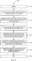
- FIG. 7 is a flowchart of method 700 in various embodiments for transferring information between meshes using feature curve networks.
- FIG. 7 begins in step 710.
- one or more feature curves associated with a first mesh are received.
- a user may manually draw or place one or more curves on the first mesh.
- information defining feature curves may be imported or loaded from a file.
- information defining feature curves may be inferred or otherwise determined from parameterizations associated with the first mesh.
- Feature curves may be user-authored on a digital object, or placed on a physical object and created when scanning to digitize the physical object.
- a first feature curve network is generated based on feature curves associated with the first mesh.
- step 740 one or more feature curves associated with a second mesh are received.
- step 750 a second feature curve network is generated based on the one or more feature curves associated with the second mesh.
- a correspondence is generated between the first mesh and the second mesh using the pair of feature curve networks (i.e., the first and second feature curve networks).
- the correspondence can be feature preserving in that the correspondence carries "important features" of the first mesh to their corresponding features on second mesh.
- step 770 information is transferred between the first mesh and the second mesh based on the correspondence.
- the transfer of information may include a unilateral or bilateral transfer or sharing of information between the first mesh and the second mesh.
- FIG. 7 ends in step 780.
- a variety of methods or tools may be provided for authoring feature curves.
- a user may specify a set of feature curves interactively using commonly available selection tools, such as shortest path selection.
- feature curves may be inferred from the discontinuities in the UV set.
- FIGS. 8A and 8B illustrate mesh 310 including a feature curve network having less than three feature curves that define a region in one embodiment.
- mesh 310 includes feature curves 810 and 820.
- a user has drawn feature curve 810 and feature curve 820 on mesh 310.
- the separation between each feature curve is illustrated by a solid dot near the top of the head and near the base of the neck.
- a feature curve may be defined by at least one point that lies within the interior of a face of mesh 310.
- Feature curve 810 and 820 can be interconnected to form a feature region.
- feature region 830 can be defined by feature curve 810 and feature curve 820.
- a set of feature curve regions on mesh 310 may define a feature curve network.
- FIGS. 9A and 9B illustrate mesh 310 including a feature curve network having more than three feature curves that define a region.
- mesh 310 includes feature curves 910, 920, 930, and 940 on mesh 360. The separation between each feature curve is illustrated by a solid dot near the top of the head, on the nose, at the base of the neck, and near the back of the neck.
- Feature curves 910, 920, 930, and 940 can be interconnected to form a feature region.
- region 950 can be defined by feature curves 910, 920, 930, and 940.
- corresponding feature curves may be constructed on a destination mesh.
- a user may copy the source feature curves as 3D curves into rough geometric proximity to the destination mesh.
- Modeling tools can be used to position the vertices of these curves near their corresponding locations on the destination mesh. The repositioned vertices can then be "snapped" onto the destination mesh to produce the destination feature curves.
- the correspondence generated by method 700 in various embodiments can provide a reasonably good starting point for most significant features, such as lips, eye brows, and ears if feature curves are appropriately positioned.
- the correspondence can be refined to match several finer resolution features, such as nostrils.
- Feature curve refinement can also be appropriate when the correspondence requires significant adjustment.
- One way to achieve refinement can be to add new feature curves to more finely partition the meshes into feature regions.
- more subtle adjustments can be provided using a lightweight and flexible method of adding additional correspondence constraints to the interior of regions created by feature curves.
- FIG. 10 is flowchart of method 1000 in various embodiments for generating a correspondence based on refinements to pair of feature curve networks.
- FIG. 10 begins in step 1010.
- a pair of feature curve networks is received.
- one or more refinements to the pair of feature curve networks are received.
- refinements to the pair of feature curve networks may include adding additional geometric primitives, such as points, lines, curves, volumes, etc. to the interior of feature regions.
- an additional pair of points may be positioned as interior constraints, one on the source, and a corresponding one on the destination.
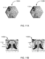
- FIG. 11A illustrates interior constraints within two corresponding regions in one embodiment.
- mesh region 1100A may be parameterized over a regular hexagon in one embodiment.
- a corresponding mesh region 1100B may similarly be parameterized over then same regular hexagon in a common parameter domain.
- a pair of points may be placed on each mesh region 1100A and 1100B to provide interior constrains to refine the correspondence.
- the pair of points may be centered in the left nostril of a source mesh and a destination mesh.
- Constraints can be arbitrarily located on the source and destination meshes and placed to reside in corresponding feature regions.
- a user may desire to specify several additional constraints per region.
- the user may specify corresponding edges, such that the additional constraints form corresponding cell complexes.
- h can be constructed as a two-dimensional harmonic deformation.
- the cage for h may be the boundary of Pm and the interior cage components correspond to interior and edge constraints.
- the correspondence is stored in step 1050.
- FIG. 10 ends in step 1060.
- FIG. 11B illustrates results of the interior constraints within the two corresponding regions in one embodiment.
- mesh region 1100A can include a scalar field 1130 indicating shader variables for the location of the left nostril of a model.
- Scalar field 1130 can be pushed through the refined correspondence to mesh region 1100B.
- the pair of points 1110 and 1120 can be used to refine the location or look of the location of the left nostril of another model.
- point 1120 may be placed to offset or lower the location of the shader variables of the left nostril.
- a new robust and controllable method for transferring data between meshes of substantially different topology and geometry can be implemented using feature curves.
- the input to the basic method can include a source mesh (e.g., possessing a set of scalar fields to be transferred), a network of feature curves on the source mesh, a destination mesh to receive the data, and a corresponding network of feature curves on the destination. From this input, a correspondence can be generated between all continuously varying points of the two surfaces. Information can be shared based on the correspondence, such that each scalar field on the source is mapped through the correspondence to define a scalar field on the destination.
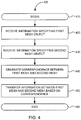
- FIG. 12 is a flowchart of method 1200 in various embodiments for generating a correspondence between meshes based on parameterization information for sharing information between the meshes.
- the processing depicted in FIG. 12 may be performed by software modules (e.g., instructions or code) executed by a processor of a computer system, by hardware modules of an electronic device, or combinations thereof.
- FIG. 12 begins in step 1210.
- a first mesh and second mesh is received.
- Information may be received that defines or otherwise specifies the first and second mesh.
- Each mesh may include a single integral mesh or may include a collection of connected meshes.
- the first and second mesh may include a collection of polygons, interconnected at vertices, that form the topology and/or geometry of a model.
- Each mesh may also include information that may further specify variables, controls, fields, rigging, color/lighting data, or the like.
- Parameterization information can include information that provides an identification of parameters associated with an object.
- a parameterization may include a complete set of effective coordinates or degrees of freedom of a system, process, or model.
- Parameterization of a line, surface or volume for example, may imply identification of a set of coordinates from which any point (on, at, or near the line, surface, or volume) may be uniquely identified by a set of numbers.
- parameterization information may include a UV set or map.
- a UV map can transform a 3D object onto a 2D image.
- the 2D image may be commonly referred to as a texture or texture map.
- the XYZ coordinates for the original 3D object in the modeling space may be parameterized over UV coordinates of the transformed 2D object.
- parameterization information may include one or more maps, harmonic parameterizations, or the like.
- a pair of feature curve networks is generated based on the parameterization information. For example, one or more partitions, divisions, or parameterizations may be identified on the first mesh from which a set of feature curves may be determined or inferred. A correspondence set of feature curves may be determined on the second mesh. Each set of feature curves can create a feature curve network.
- a correspondence is generated between the first mesh and the second mesh based on the pair of feature curve networks.
- the correspondence can include functions, relationships, correlations, etc. between one or more points associated with the first mesh and one or more points associated with second mesh.
- the correspondence may include a mapping from every location on or within a space near the first mesh to a unique location on or near the second mesh.
- the correspondence may map one or more points, curves, surfaces, regions, objects, or the like, associated with the first object to one or more points, curves, surfaces, regions, objects, or the like associated with the second object.
- the correspondence can be represented by a parameterization built for source and destination meshes over a common domain.
- This common parameter domain can provide a global and continuous correspondence between all points of the source and destination surfaces.
- the correspondence may rely on feature curve networks which may, in part, be automatically created based on parameterization information, from user-supplied points, user-supplied curves, other discontinuities, or the like.
- FIG. 12 ends in step 1260.
- FIG. 13 is a flowchart of method 1300 in various embodiments for generating a correspondence between meshes based on UV sets.
- FIG. 13 begins in step 1310.
- a mesh is received.
- FIG. 14A illustrates mesh 1410 in one embodiment.
- Mesh 1410 in this example, appears as a cube.
- a UV set is received in step 1330.
- FIG. 14B illustrates UV map 1420 associated with mesh 1410.
- step 1340 of FIG. 13 one or more user-defined feature curves are received.
- step 1350 one or more feature curves are determined based on the UV set (e.g., UV map 1420).
- step 1360 a feature curve network is generated based on the user-defined feature curves and the features curves determined from the UV-set.
- FIG. 13 ends in step 1370.
- a source mesh may possess a UV set that parameterizes regions that are separately shaded.
- a UV set that parameterizes regions that are separately shaded.
- each face of the cube mesh 1410 shown in FIG. 14A may be separately shaded.
- the UV regions can be used as parametric domains to be used to build a global and continuous correspondence between all points of the source and destination surfaces. Therefore, feature curves can be inferred to "cover" the boundaries of the UV regions. That is, if the UV set is discontinuous on an edge V i V j of the source mesh M , then exactly one feature curve contains V i Vj.
- the UV set can be transferred to M' in two steps:
- a feature curve inference algorithm can be based on an analysis of an auxiliary structure called a seam complex.
- the seam complex may consists of a set of edges, one per seam edge of the source mesh M .
- An edge can be a seam edge if either its org or dest vertices has different attribute values with respect to the two faces meeting at the edge.
- critical vertices may be identified and processed one at a time.
- a critical vertex can include a vertex with other than two incident seam edges.
- Critical vertices can represent feature curve endpoints. Once the critical vertices have been processed, there may still be one or more closed loops. For each of these, an arbitrary vertex may be chosen as the feature curve endpoint and the loop is traced until it closes back on itself.
- a new robust and controllable method for transferring data between meshes of substantially different topology and geometry can be implemented using feature curves.
- the input to the basic method can include a source mesh (e.g., possessing a set of scalar fields to be transferred), a network of feature curves on the source mesh, a destination mesh to receive the data, and a corresponding network of feature curves on the destination. From this input, a correspondence can be generated between all continuously varying points of the two surfaces. Information can be shared based on the correspondence, such that each scalar field on the source is mapped through the correspondence to define a scalar field on the destination.
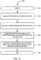
- FIG. 15 is a simplified flowchart of method 1500 in various embodiments for generating a volume correspondence between meshes for sharing information between the meshes.
- the processing depicted in FIG. 15 may be performed by software modules (e.g., instructions or code) executed by a processor of a computer system, by hardware modules of an electronic device, or combinations thereof.
- FIG. 15 begins in step 1510.
- a pair of surfaces is received.
- information may be received specifying a surface or region of a source mesh and a corresponding surface or region of a destination mesh.
- the pair of surfaces may be authored by a user or determined based on one or more discontinuities, parameterizations, or the like.
- Feature curves may be used to partition a source mesh and a destination mesh into a pair of feature curve networks.
- the pair of surfaces may be identified within the pair of feature curve networks.
- a surface correspondence is generated based on the pair of surfaces.
- the surface correspondence can include functions, relationships, correlations, etc. between one or more points associated with a first surface and one or more points associated with a second surface.
- the surface correspondence may include a mapping from every location on the first surface to a unique location on the second surface.
- the correspondence may map one or more points, curves, surfaces, regions, objects, or the like, associated with the first object to one or more points, curves, surfaces, regions, objects, or the like associated with the second object.
- a parameterization is built for source and destination meshes over a common domain. This common parameter domain can then be used to build the global and continuous surface correspondence between all points of the source and destination surfaces.
- the basic framework of the parameterization may rely on user-supplied points, user-supplied curves, inferred discontinuities, or the like.
- the parameterization may include a set of feature curves defining a feature curve network.
- a volume correspondence is generated based on the surface correspondence.
- the volume correspondence can include functions, relationships, correlations, etc. between one or more points associated with a first volume or other n-D space and one or more points associated with a second volume or n-D space.
- the volume correspondence may include a mapping from every location on and within the first volume to a unique location on or within the second volume.
- the correspondence may map one or more points, curves, surfaces, regions, objects, volumes, n-D spaces, (n-1)-D spaces, or the like, associated with a first object to one or more corresponding points, curves, surfaces, regions, objects, volumes, n-D spaces, (n-1)-D spaces, or the like associated with a second object.
- the volume correspondence may include a harmonic deformation correspondence.
- the harmonic deformation correspondence may provide non-negativity and interior locality for volume deformation techniques using a topologically flexible structure, called a cage, that may consists of a closed three dimensional mesh.
- the cage can optionally be augmented with additional interior vertices, edges, and faces to more precisely control the interior behavior of the deformation.
- Harmonic coordinates can be generalized barycentric coordinates that can be extended to any dimension, providing non-negativity in strongly concave situations, and having magnitudes that fall off with distance as measured within the cage.
- FIG. 15 ends in step 1550.
- FIG. 16 is an illustration of a volume correspondence between volume 1610 and volume 1620.
- a cube can be constructed to represent volume 1610.
- Found within volume 1610 is a mesh object in the form of a human head.
- a corresponding cube can be constructed to represent volume 1620.
- the volume correspondence can provide a mapping from every location in or on volume 1610 to a unique location in or on volume 1620.
- point 1630A can be mapped via the volume correspondence to point 1630B.
- information may be shared or otherwise transferred between a first mesh and a second mesh based on the volume correspondence.
- the information may include character rigging, topology data, geometry data, shader variables, hair objects, information or objects within a proximity to either mesh, painter data, or the like, that may be found at, found near, found on, found in, protruding from, or extending into an object.
- the transfer of information may occur from a first mesh to a second mesh. The transfer may also occur from the second mesh to the first mesh.
- FIG. 17 illustrates a first mesh and a corresponding second mesh for transferring hair styles in one embodiment.
- mesh 1710 is formed to represent a head of a human character.
- An animator or other artist may construct a hair style 1720 (e.g., a mohawk) for the character.
- Hair style 1720 may include linear objects, fields, variables, lighting information, or the like, for example, to represent the hair, its position relative to mesh 1710, position of individual hairs or objects with respect to each other, how the hair interacts with other objects, or the like.
- hair style 1720 can be placed on top of mesh 1710, substantially in the center.
- the location or position of hair variables or hair objects associated with hair style 1720 may be shared or otherwise transferred to other objects using a surface correspondence.
- a first set of feature curves may be authored or otherwise placed on mesh 1710 to create a first feature curve network.
- a corresponding second set of feature curves may be authored or otherwise placed on mesh 1730 to create a second set of feature curves.
- a surface correspondence may be generated that maps points or locations on mesh 1710 to points or locations on mesh 1730. Information at or near a point on mesh 1710 can be transferred to a corresponding point on mesh 1730.
- hair style 1720 may be shared or otherwise transferred to other objects using a volume correspondence.
- the surface correspondence between mesh 1710 and 1730 may allow the mapping of the points at which hair objects are connected to mesh 1710, and thus are associated with a partition create by the first feature curve network.
- the surface correspondence may be extending in one or more dimensions using points, lines, curves, surfaces, surface regions, or other geometric primitives and objects that may be placed relative of a surface associated with mesh 1710 to construct volumes or other n-D spaces.
- Corresponding volumes or other n-D spaces may be constructed for mesh 1730.
- a volume correspondence may be created based on the surface correspondence that maps points or locations within a first volume or n-D space to unique points or locations in a corresponding volume or n-D space.
- surface 1740 may be positioned relative to mesh 1710. Based on all or a portion of mesh 1710 (e.g., the surface or region below hair style 1720) and surface 1740 a volume or other n-D space may be constructed. A corresponding surface 1750 may be positioned relative to destination mesh 1730. Based on all or a portion of mesh 1730 (e.g., a surface region on the scalp where hairs are desired to be placed) and surface 1750 a corresponding volume or other n-D space may be constructed. Information associated with hair style 1730, such as torsion and spring variables, can be transferred between corresponding volumes or n-D spaces based on the volume correspondence to create hair style 1760. Other transformations, such as scaling, rotation, translation, or the like may occur during or post transfer.
- volume correspondences between meshes and the transfer of information can be applied to a range of applications.
- information may be shared between characters.
- sharing can be accomplished between meshes with far more topological flexibility.
- the flexibility of evolving characters may be achieved.
- the geometry and mesh topology of the character may change. Changes can be made to variables, hair style parameters, clothing, or the like, and transferred between models.
- FIG. 18 is a simplified flowchart of method 1800 in various embodiments for shape blending.
- the processing depicted in FIG. 18 may be performed by software modules (e.g., instructions or code) executed by a processor of a computer system, by hardware modules of an electronic device, or combinations thereof.
- FIG. 18 begins in step 1810.
- a collection of meshes is received.
- the collection may include one or more meshes or references to a set of meshes.
- the collection may include meshes for models having identical, similar, or different topologies, geometries, or the like.
- each correspondence between a pair of meshes can include functions, relationships, correlations, etc. between one or more points associated with a first mesh and one or more points associated with a second mesh.
- the correspondence may include a mapping from every location on or within a space near the first mesh to a unique location on or near the second mesh.
- the correspondence may map one or more points, curves, surfaces, regions, objects, or the like, associated with the first object to one or more points, curves, surfaces, regions, objects, or the like associated with the second object.
- the correspondence may include a surface correspondence and/or a volume correspondence.
- a parameterization is built for the pairs meshes over a common domain. This common parameter domain can then be used to build a global and continuous correspondence between all points of the source and destination surfaces.
- the basic framework of the parameterization may rely on user-supplied points, user-supplied curves, inferred discontinuities, or the like.
- the parameterization may include a set of feature curves defining a feature curve network.
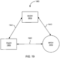
- FIG. 19 is a block diagram of collection 1900 of meshes in one embodiment.
- collection 1900 can include meshes 1910, 1920, and 1930.
- Meshes 1910 and 1920 may have an identical or substantially similar topology (as indicated by the common rectangular shape).
- Mesh 1930 may have a different topology than meshes 1910 and 1920 (as indicated by a circular shape).
- correspondence 1940 may be created between meshes 1910 and 1920
- correspondence 1950 may be created between meshes 1910 and 1930
- correspondence 1960 may be created between meshes 1920 and 1930.
- the correspondences may be created using features curve networks, in which one or more feature curves may be user authored or automatically determined in response to parameterization information associated with a mesh.
- the correspondences may include one or more surfaces correspondences and/or one or more volume correspondences.
- step 1840 information associated with a plurality of meshes is combined based on the correspondences.
- information associated with meshes 1910 and 1920 in collection 1900 may be combined based on correspondence 1940.
- information of type A from mesh 1910 may be combined with information of type A from mesh 1920 to create blended information of type A.
- the information from mesh 1910 may be summed, averages, or otherwise procedurally process with the information from mesh 1920 to generate like information of type A.
- information of type A from mesh 1910 may be combined with information of type B from mesh 1920 to create blended information of a set of type A and B.
- correspondences may be created between pairs of meshes in a collection of meshes.
- Information associated with a plurality of meshes can be "pushed" through the correspondences and blended or otherwise combined to create combinations of data that reflect new topologies, geometries, scalar fields, hair styles, or the like that may be transferred to a mesh of new or existing models.
- information can be shared, combined, and blended between meshes that may include differing topologies and geometries from other meshes in a collection.
- FIG. 18 ends in step 1850.
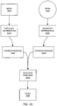
- FIG. 20 is a block diagram illustrating blending of topology information and geometry information in one embodiment.
- topology information 2010 from mesh 1910 of FIG. 19 is pushed through correspondence 1940 with mesh 1920.
- Geometry information 2020 from mesh 1930 is pushed through correspondence 1960 with mesh 1920.
- Blending function 2030 receives topology information 2010 and geometry information 2020 for application to mesh 1920. Since correspondences 1940 and 1960 provide full correspondences between all points between meshes 1910 and 1920, and between meshes 1930 and 1920, respectively, lending function 2030 can apply blended or combined information to corresponding points on mesh 1920. Blending function 2030 may include one or more values, parameters, attributes, or the like for controlling the weighting, scaling, or transformation of the blending or transfer of common types or different types of information from other meshes.
- FIGS. 21A, 21B , and 21C illustrate a collection of meshes and a resultant blend in one embodiment.
- human character 2105 can be represented using mesh 2110.
- Mesh 2110 may include a first topology and provide the geometry to character 2105. For example, character 2105 may appear to be tall and thin.
- Mesh 2110 may include a feature curve network 2115.
- Feature curve network 2115 may include a set of feature curves (e.g., black lines with in-line arrows) that partition mesh 2115 into a collection of feature regions.
- human character 2120 can be represented using mesh 2125.
- Mesh 2125 may include a second topology (i.e., a topology different from the first topology of character 2105) and provide the geometry of character 2120.
- character 2120 may appear to be stocky and over-weight.
- Mesh 2125 may include a feature curve network 2130.
- Feature curve network 2130 may include a set of feature curves that partition mesh 2125 into a collection of feature regions.
- human character 2140 may be created using a blend of information from characters 2105 and 2120. Character 2140 may be represented by mesh 2145. In one example, a correspondence may be generated between mesh 2105 and mesh 2145 using feature curve network 2115 and a corresponding feature curve network placed on mesh 2145. Another correspondence may be generated between mesh 2120 and mesh 2145 using feature curve network 2130 and a corresponding feature curve network placed on mesh 2145. The same feature curve network placed on mesh 2145 may be used for created the correspondences. Alternatively, different feature curve networks may be used.
- the first topology of character 2105 may be transferred to mesh 2145 of character 2140.
- the first topology information of character 2105 may be blended with geometry information transferred from character 2120 using one or more correspondences to create character 2140. For example, a user or animator may use a correspondence to blend the first topology of character 2105 with 60% of the geometry of character 2120 to create character 2140.
- information from a plurality of meshes in a collection may be blended or combined using correspondences between pairs of the meshes.
- the combined information can be used to create combinations of data that reflect new topologies, geometries, scalar fields, hair styles, or the like that may be transferred to a mesh of new or existing models.
- information can be shared, combined, and blended between meshes that may include differing topologies and geometries from other meshes in a collection.
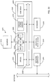
- FIG. 22 is a block diagram of computer system 2200 that may be used to implement or practice various embodiments of an invention whose teachings may be presented herein.
- FIG. 22 is merely illustrative of a general-purpose computer system or specific information processing device for an embodiment incorporating an invention whose teachings may be presented herein and does not limit the scope of the invention as recited in the claims.
- One of ordinary skill in the art would recognize other variations, modifications, and alternatives.
- computer system 2200 can include monitor 2210, computer 2220, keyboard 2230, user input device 2240, computer interfaces 2250, or the like.
- Monitor 2210 may typically include familiar display devices, such as a television monitor, a cathode ray tube (CRT), a liquid crystal display (LCD), or the like.
- Monitor 2210 may provide an interface to user input device 2240, such as incorporating touch screen technologies.
- Computer 2220 may typically include familiar computer components, such as processor 2260 and one or more memories or storage devices, such as random access memory (RAM) 2270, one or more disk drives 2280, graphics processing unit (GPU) 2285, or the like.
- Computer 2220 may include system bus 2290 interconnecting the above components and providing functionality, such as inter-device communication.
- computer 2220 may include one or more microprocessors (e.g., single core and multi-core) or micro-controllers, such as PENTIUM, ITANIUM, or CORE 2 processors from Intel of Santa Clara, California and ATHLON, ATHLON XP, and OPTERON processors from Advanced Micro Devices of Sunnyvale, California. Further, computer 2220 may include one or more hypervisors or operating systems, such as WINDOWS, WINDOWS NT, WINDOWS XP, VISTA, or the like from Microsoft or Redmond, Washington, SOLARIS from Sun Microsystems, LINUX, UNIX, and UNIX-based operating system.
- microprocessors e.g., single core and multi-core
- micro-controllers such as PENTIUM, ITANIUM, or CORE 2 processors from Intel of Santa Clara, California and ATHLON, ATHLON XP, and OPTERON processors from Advanced Micro Devices of Sunnyvale, California.
- computer 2220
- user input device 2240 may typically be embodied as a computer mouse, a trackball, a track pad, a joystick, a wireless remote, a drawing tablet, a voice command system, an eye tracking system, or the like.
- User input device 2240 may allow a user of computer system 2200 to select objects, icons, text, user interface widgets, or other user interface elements that appear on monitor 2210 via a command, such as a click of a button or the like.
- computer interfaces 2250 may typically include a communications interface, an Ethernet card, a modem (telephone, satellite, cable, ISDN), (asynchronous) digital subscriber line (DSL) unit, FireWire interface, USB interface, or the like.
- computer interfaces 2250 may be coupled to a computer network, to a FireWire bus, a USB hub, or the like.
- computer interfaces 2250 may be physically integrated as hardware on the motherboard of computer 2220, may be implemented as a software program, such as soft DSL or the like, or may be implemented as a combination thereof.
- computer system 2200 may also include software that enables communications over a network, such as the Internet, using one or more communications protocols, such as the HTTP, TCP/IP, RTP/RTSP protocols, or the like.
- communications protocols such as the HTTP, TCP/IP, RTP/RTSP protocols, or the like.
- other communications software and/or transfer protocols may also be used, for example IPX, UDP or the like, for communicating with hosts over the network or with a device directly connected to computer system 2200.
- RAM 2270 and disk drive 2280 are examples of machine-readable articles or computer-readable media configured to store information, such as computer programs, executable computer code, human-readable source code, shader code, rendering enginges, or the like, and data, such as image files, models including geometrical descriptions of objects, ordered geometric descriptions of objects, procedural descriptions of models, scene descriptor files, or the like.
- Other types of computer-readable storage media or tangible machine-accessible media include floppy disks, removable hard disks, optical storage media such as CD-ROMS, DVDs and bar codes, semiconductor memories such as flash memories, read-only-memories (ROMS), battery-backed volatile memories, networked storage devices, or the like.
- GPU 2285 may include any conventional graphics processing unit. GPU 2285 may include one or more vector or parallel processing units that may be user programmable. Such GPUs may be commercially available from NVIDIA, ATI, and other vendors. In this example, GPU 2285 can include one or more graphics processors 2293, a number of memories and/or registers 2295, and a number of frame buffers 2297.
- FIG. 22 is merely representative of a general-purpose computer system or specific data processing device capable of implementing or incorporating various embodiments of an invention presented within this disclosure.
- a computer system or data processing device may include desktop, portable, rack-mounted, or tablet configurations.
- a computer system or information processing device may include a series of networked computers or clusters/grids of parallel processing devices.
- a computer system or information processing device may techniques described above as implemented upon a chip or an auxiliary processing board.
- any of one or more inventions whose teachings may be presented within this disclosure can be implemented in the form of logic in software, firmware, hardware, or a combination thereof.
- the logic may be stored in or on a machine-accessible memory, a machine-readable article, a tangible computer-readable medium, a computer-readable storage medium, or other computer/machine-readable media as a set of instructions adapted to direct a central processing unit (CPU or processor) of a logic machine to perform a set of steps that may be disclosed in various embodiments of an invention presented within this disclosure.
- CPU or processor central processing unit
- the logic may form part of a software program or computer program product as code modules become operational with a processor of a computer system or an information-processing device when executed to perform a method or process in various embodiments of an invention presented within this disclosure.
- code modules become operational with a processor of a computer system or an information-processing device when executed to perform a method or process in various embodiments of an invention presented within this disclosure.
- One aspect of the present invention provides a computer-implemented method for generating correspondences for transferring information between objects, the method comprising receiving a first mesh; receiving a first feature curve network associated with the first mesh; receiving a second Mesh; receiving a second feature curve network associated with the second mesh; and generating a correspondence between the first mesh and the second mesh using one or more harmonic functions in response to the first feature curve network associated with the first mesh and the second feature curve network associated with the second mesh.
- One aspect of the present invention provides a computer-implemented method for generating correspondences for transferring information between objects, the method comprising receiving a first pair of surfaces; generating a surface correspondence based on the pair of surfaces; and generating a volume correspondence based on the surface correspondence.
- the method further comprises transferring information between volumes associated with the pair of surfaces based on the volume correspondence.
- generating the volume correspondence comprises generating the volume correspondence in response to a second pair of surfaces
- the method further comprises generating a harmonic reformation correspondence based on the second pair of surfaces.
- generating the surface correspondence comprises generating the surface correspondence based on a pair of feature curve networks associated with the pair of surfaces.
- the method further comprises receiving a set of constraints associated with the pair of surfaces; and wherein generating the volume correspondence comprises generating the volume correspondence based on the set of constraints.
- the present invention provides a computer-implemented method for generating correspondences for transferring information between collections of objects, the method comprising receiving a collection of meshes, the collection of meshes having at least 2 topologies; generating a correspondence between all pairs in the collection of meshes; and combining information associated with a plurality of meshes in the collection of meshes based on the correspondence.
- combining the information associated with the plurality of meshes in the collection of meshes comprises combining shape associated with two or more meshes in the collection of meshes.
- combining the information associated with the plurality of meshes in the collection of meshes comprises combining geometry associated with two or more meshes in the collection of meshes.
- the method further comprises generating an output mesh based on the combined information.
- generating the correspondence between all pairs in the collection of meshes comprises generating the correspondence between each mesh in the collection of meshes and an output mesh in the collection of meshes.
- generating the correspondence between all pairs in the collection of meshes comprises generating the correspondence based on one or more harmonic functions.
- generating the correspondence between all paints in the collection of meshes comprises generating the correspondence based on a set of feature curve networks associated witch the meshes.
- the set of feature curve networks comprise at least one feature curve that is defined by at least one point that lies in the interior of a face associated with one of the meshes in the collection of meshes.
- One aspect of the present invention provides a method for detailing differences between objects, the method comprising receiving a collection of meshes, the collection of meshes having at least 2 topologies; generating a correspondence between all pairs in the collection of meshes; and combining information associated with a plurality of meshes in the collection of meshes based on the correspondence; determining difference information based on the correspondence; and storing the difference information.
- storing the difference information comprising storing the difference information as a bump map.
- storing the difference information comprising storing the difference information as a set of wavelet coefficients.
Landscapes
- Engineering & Computer Science (AREA)
- Physics & Mathematics (AREA)
- General Physics & Mathematics (AREA)
- Theoretical Computer Science (AREA)
- Computer Graphics (AREA)
- Software Systems (AREA)
- Computer Hardware Design (AREA)
- General Engineering & Computer Science (AREA)
- Architecture (AREA)
- Geometry (AREA)
- Processing Or Creating Images (AREA)
- Image Generation (AREA)
Description
- This application claims priority to and the benefit of
U.S. Provisional Patent Application No. 61/030,796, filed February 22, 2008 U.S. Patent Application No. 12/200,704, filed August 28, 2008 U.S. Patent Application No. 12/200,719, filed August 28, 2008 U.S. Patent Application No. 12/200, 727, filed August 28, 2008 U.S. Patent Application No. 12/200,739, filed August 28, 2008 - This disclosure relates to computer animation and computer generated imagery. More specifically, this disclosure related to techniques for transferring information from one computer model to another.
- With the wide-spread availability of computers, animators and computer graphics artists can rely upon computers to assist in the animation and computer generated imagery process. This may include using computers to have physical models be represented by virtual models in computer memory. This may also include using computers to facilitate animation, for example, by the designing, posing, deforming, coloring, painting, or the like, of characters or other elements of a computer animation display.
- Pioneering companies in the computer-aided animation / computer generated imagery (CGI) industry can include Pixar. Pixar is more widely known as Pixar Animation Studios, the creators of animated features such as "Toy Story" (1995) and "Toy Story 2" (1999), "A Bugs Life" (1998), "Monsters, Inc." (2001), "Finding Nemo" (2003), "The Incredibles" (2004), "Cars" (2006), "Ratatouille" (2007), and others. In addition to creating animated features, Pixar develops computing platforms specially designed for computer animation and CGI, now known as RenderMan®. RenderMan® is now widely used in the film industry and the inventors have been recognized for their contributions to RenderMan® with multiple Academy Awards®.
- One core functional aspect of RenderMan® software can include the use of a "rendering engine" to convert geometric and/or mathematical descriptions of objects or other models into images. This process is known in the industry as "rendering." For movies or other features, a user (e.g., an animator or other skilled artist) specifies the geometric description of a model or other objects, such as characters, props, background, or the like that may be rendered into images. An animator may also specifying poses and motions for objects or portions of the objects. In some instances, the geometric description of objects may include a number of animation variables (avars), and values for the avars.
- The production of animated features and CGI may involve the extensive use of computer graphics techniques to produce a visually appealing image from the geometric description of an object or model that can be used to convey an element of a story. One of the challenges in creating models for use in animated features can be balancing the desire for a visually appealing image of a character or other object with the practical issues involved in allocating the computational resources required to produce those visually appealing images. Often the geometric descriptions of objects or models at various stages in a feature film production environment may be rough and course, lacking the realism and detail that would be expected of the final production.
- One issue with the production process is the time and effort involved when an animator undertakes to create the geometric description of a model and the models associated avars, rigging, shader variables, paint data, or the like. Even with models that lack the detail and realism expected of the final production, it may take several hours to several days for an animator to design, rig, pose, paint, or otherwise prepare the model for a given state of the production process. Further, although the model need not be fully realistic at all stages of the production process, it can be desirable that the animator or artist producing the model be able to modify certain attributes of the model at any stage. However, modifying the model during the production process may also involved significant time and effort. Often, there may not be sufficient time for desired modifications in order to maintain a release schedule.
- Accordingly, what is desired is to solve problems relating to transferring information between meshes, some of which may be discussed herein. Additionally, what is desired is to reduce drawbacks related to transferring information between meshes, some of which may be discussed herein.
- In various embodiments, data and other information from one model can be transferred to another model. A correspondence between meshes of the models can be created that provides a transfer or sharing of information to include all points of one mesh and all points of the other mesh. Mesh information and other proximity data from the mesh of one model can be "pushed through" the correspondence to transfer the data to its designated location at the mesh of the other model.
- The correspondence between each of the meshes can enable animators and other digital artists to create new characters from existing characters that may have different topologies and geometries. Additionally, the correspondence may be created between different versions of the same character, thereby allowing the animator to implement changes to characters at later stages of the production process and transfer information from prior versions thereby preserving previous work product and reducing the time and cost of updating the characters.
- In some embodiments, correspondences for sharing or transferring information between meshes can be generated based on a pair of feature curve networks. A correspondence can be authored on a source mesh by drawing or placing one or more geometric primitives (e.g., points, lines, curves, volumes, etc.) at the source mesh and corresponding geometric primitives at a destination mesh. For example, a collection of "feature curves" may be placed on each of the source and destination meshes to partition the source and destination meshes into a collection of "feature regions" at "features" or other prominent aspects of the model, such as eyes, noses, or lips. The resulting partitions forming "feature curve networks" can be used to construct a full correspondence between all points of the source mesh and all points of the destination mesh.
- In further embodiments, feature curve networks forming the resulting partitions may be different from three sided polygons (e.g., different from triangles), which may commonly be used to create meshes. At least one region associated with the source mesh or the destination mesh may be bounded by more than three feature curves in the pair of feature curve networks. At least one region associated with the source mesh or the destination mesh may be bounded by less than three feature curves in the pair of feature curve networks. The correspondence may be generated based on the pair of feature curve networks where regions associated with the source mesh or the destination mesh are bounded by less than three or more than three feature curves.
- In some embodiments, at least one feature curve may be defined by at least one point that lies within the interior of a face associated with either the source mesh or the destination mesh. A pair of feature curve networks may include one or more user-defined feature curves. Feature curves associated with a pair of feature curve networks may be inferred from other parameterizations of a source or destination mesh.
- In various embodiments, at least a portion of the pair of feature curve networks may be created based on parameterization information associated with one or more of the meshes. The parameterization information may include UV sets, one or more maps, harmonic parameterizations, or other information from which discontinuities may be inferred. In one embodiment, the correspondence may be generated by created one or more maps.
- In further embodiments, the surface correspondence between one model and another model may be used to generate a volume correspondence. A volume correspondence may be generated based on a pair of surfaces and at least one additional pair of surfaces from which a volume or other n-D space can be defined. The resulting volume correspondence can be used to share or transfer information between all points within a volume or other n-D space defined for a source model and all points within a corresponding volume or other n-D space defined for a destination model. In at least one embodiment, the volume correspondence can be built using a harmonic deformation correspondence.
- A volume correspondence in some embodiments can be authored on a source model by a user drawing or placing one or more corresponding feature curves on a source mesh and a destination mesh. The user may draw or place corresponding pairs of surfaces external to the models or within the models to define a volume of other n-D space. The volume correspondence may be generated in response to the corresponding feature curves on the source and destination meshes and the corresponding pairs of surfaces that define the volume or other n-D space.
- In various embodiments, data and other information of models can be shared to be combined to create new models or update features of existing models. A correspondence between pairs of meshes in a collection of meshes can be created. The correspondences may enable an animator or artist to share, blend, or combine information from a plurality of meshes. Mesh information and other data at, near, or otherwise associated with the models can be "pushed through" the correspondences and combined or blended with information from other models.
- In various embodiments, difference information between a plurality of meshes may be determined based on the correspondence. The difference information may be stored. For example, the difference information may generated and stored as a bump map. Alternatively, the difference between a set of meshes may be determined and information indicative of the difference may be generated and stored as a set of wavelet coefficients.
- In still further embodiments, a correspondence between a source mesh and a destination mesh can be created or generated based on one or more harmonic functions. The correspondence may be generated such that data corresponding to a first point at or near the source mesh may be shared or transferred to a second point at or near destination mesh. The information sharing between two or more meshes may unidirectional or bidirectional based on the correspondence. Thereby, information may be shared between two or more meshes, such as scalar fields, variables, controls, avars, articulation data, character rigging, shader data, lighting data, paint data, simulation data, topology and/or geometry, re-meshing information, map information, or the like.
- In one embodiment, a computer-implemented method may be provided for generating correspondences for transferring information between objects. A first mesh or mesh object may be created, loaded, or otherwise received. A second mesh or mesh object may be created, loaded, or otherwise received. A pair of feature curve networks then may be created or received. At least one region of the first mesh or at least one region of the second mesh may be bounded by more than three or less than three feature curves in the pair of feature curve networks. A correspondence between the first and second meshes may then be generated or otherwise established based on the pair of feature curve networks.
- In yet another embodiment, a correspondence may be generated between the first mesh and the second mesh using one or more harmonic functions. In a further embodiment, a correspondence may be generated based on a pair of feature curve networks where at least one feature curve in the pair of feature curve networks is defined by a point that lies in the interior of a face associated with one of a first mesh or a second mesh.
- A further understanding of the nature, advantages, and improvements offered by those inventions disclosed herein may be realized by reference to remaining portions of this disclosure and any accompanying drawings.
- In order to better describe and illustrate embodiments and/or examples of any inventions presented within this disclosure, reference may be made to one or more accompanying drawings. The additional details or examples used to describe the accompanying drawings should not be considered as limitations to the scope of any of the disclosed inventions, any of the presently described embodiments and/or examples, or the presently understood best mode of any invention presented within this disclosure.
-
FIG. 1 is a simplified block diagram of a system for creating computer animations and computer graphics imagery that may implement or incorporate various embodiments of an invention whose teachings may be presented herein; -
FIG. 2 is an illustration of a mesh for a head of a human character; -
FIG. 3A is an illustration a mesh including various pieces of associated information; -
FIG. 3B is an illustration of a mesh in various embodiments with which information associated with the mesh ofFIG. 3A may be shared; -
FIG. 4 is a simplified flowchart of a method in various embodiments for generating a correspondence between meshes for sharing information between the meshes; -
FIG. 5 is an illustration of a correspondence between a first region and a second region in some embodiments; -
FIG. 6 illustrates a first mesh region and a corresponding second mesh region parameterized over a regular hexagon in one embodiment; -
FIG. 7 is a flowchart of a method in various embodiments for transferring information between meshes using feature curve networks; -
FIGS. 8A and 8B illustrate a mesh including a feature curve network having less than three feature curves that define a region; -
FIGS. 9A and 9B illustrate a mesh including a feature curve network having more than three feature curves that define a region; -
FIG. 10 is a flowchart of a method in various embodiments for generating a correspondence based on refinements to pair of feature curve networks; -
FIGS. 11A and 11B illustrate interior constraints within two corresponding regions in one embodiment; -
FIG. 12 is a flowchart of a method in various embodiments for generating a correspondence between meshes based on parameterization information for sharing information between the meshes; -
FIG. 13 is a flowchart of a method in various embodiments for generating a correspondence between meshes based on UV sets; -
FIGS. 14A and 14B illustrate a model and its corresponding UV map in one embodiment; -
FIG. 15 is a simplified flowchart of a method in various embodiments for generating a volume correspondence between meshes for sharing information between the meshes; -
FIG. 16 is an illustration of a volume correspondence between a first volume and a second volume in some embodiments; -
FIG. 17 illustrates a first mesh and a corresponding second mesh for transferring hair styles in one embodiment; -
FIG. 18 is a simplified flowchart of a method in various embodiments for shape blending; -
FIG. 19 is a block diagram of a collection of meshes in one embodiment; -
FIG. 20 is a block diagram illustrating blending of topology information and geometry information in one embodiment; -
FIGS. 21A, 21B , and21C illustrate a collection of meshes and a resultant blend in one embodiment; and -
FIG. 22 is a block diagram of a block diagram of a computer system or information processing device that may be used to implement or practice various embodiments of an invention whose teachings may be presented herein. - Techniques and tools can be implemented that assist in the production of computer animation and computer graphics imagery. A mesh can be the structure that gives shape to a model. The mesh of a model may include, in addition to information specifying vertices and edges, various additional pieces of information. In various embodiments, point weight groups, shader variables, articulation controls, hair variables and styles, paint data, or the like, can be shared between meshes having different topologies and geometries. Information associated with the mesh of one character can be shared with or transferred to the mesh of another character, even from one character to another completely different character and between different versions of the same character.
- A correspondence build between a source mesh and a destination mesh can provide the sharing of information on, at, or near one mesh to designated locations of another mesh. The correspondence may be constructed between all points on surfaces of the meshes, rather than merely mesh vertices alone. In various embodiments, the correspondences may be authored by drawing out points, lines, curves, etc. on a source mesh and associated points, lines, curves, etc. on a destination mesh. These may correspond to features or other prominent aspects of models provide by the meshes. Regions created by authoring on the meshes can be parameterized such that a full correspondence is created between all points of the source mesh and all points of the destination mesh, without requiring identical topologies and/or geometries.
-
FIG. 1 is a simplified block diagram ofsystem 100 for creating computer animations and computer graphics imagery that may implement or incorporate various embodiments of an invention whose teachings may be presented herein. In this example,system 100 includesdesign computer 110,object library 120,object modeler 130,object simulator 140, and object render 150. -
Design computer 110 can be any PC, laptop, workstation, mainframe, cluster, or the like.Object library 120 can be any database configured to store information related to objects that may be designed, posed, animated, simulated, rendered, or the like. -
Object modeler 130 can be any hardware and/or software configured to model objects.Object modeler 130 may generate 2-D and 3-D object data to be stored inobject library 120.Object simulator 140 can be any hardware and/or software configured to simulate objects.Object simulator 140 may generate simulation data using physically-based numerical techniques.Object renderer 150 can be any hardware and/or software configured to render objects. For example, objectrenderer 150 may generate still images, animations, motion picture sequences, or the like of objects stored inobject library 120. -
FIG. 2 is an illustration ofmesh 200 for a head of a human character model in one embodiment. Mesh 200 can be created or modeled as a collection of faces (e.g., triangles, quadrilaterals, or other polygons), formed by interconnecting a collection of vertices. In this example, a collection of polygons interconnect atvertex 210. Polygons may interconnect atvertex 210 to share an edge (e.g., edge 220). Any number of polygons and vertices may be used to formmesh 200. The number of polygons may be dependent on user preference, the desired topology, geometry, realism, detail, or the like. - Motion of a model associated with
mesh 200 may be realized by controllingmesh 200, for example by controllingvertices mesh 200 may be individually animated by moving their location in space (x, y, z) for each displayed frame of a computer animation. Polygons and vertices ofmesh 200 may also move together as group, maintaining constant relative position. Thus, for example, by raising vertices ofmesh 200 by appropriate amounts at the corners of lips on the head of the human character, a smiling expression can be formed. Similarly, vertices ofmesh 200 located at or near features or other prominent aspects of the model created bymesh 200, such as eyebrows, cheeks, forehead, etc. may be moved to deform the head of the human character to form a variety of expressions. - In addition to controlling character deformations, information can be "attached to" mesh 200 to provide other functional and/or decorative purposes. For example, mesh 200 may be connected to skeletons, character rigging, or other animations controls and avars used to animate, manipulate, or deform the model via
mesh 200. Further, fields of data and/or variables specifying color, shading, paint, texture, etc. can be located at certain vertices or defined over surfaces ofmesh 200. As discussed above, constructingmesh 200 and placing all of this information onmesh 200 can be a time consuming process. This process may limit how many characters or other objects maybe created, the topologies and geometries of those models, and what changes can be made during various stages in the production of animations, such as feature-length films. -
FIG. 3A is anillustration mesh 310 including various pieces of associated information. Mesh 310 can includescalar field 320, animations controls 330, topology/geometry data 340, andpainter data 350.Scalar field 320 may include a distribution of values or variables over a portion ofmesh 310. The values or variables associated withscalar field 320 may include shader variables, point weight groups, the location of hair/fur objects, or the like. Topology/geometry data 340 may include information that defines or describes a locality in terms of its layout, structure, or level of detail.Painter data 350 may include information, such as coloring and textures, placed by an animator or designer at a specific location onmesh 310. - In various embodiments, new models can be created and existing models can be more readily updated using techniques of this disclosure that allow animators to overcome some of the timing constraints involved in creating models. Additionally, the time and effort put into designing one model can be preserved allowing the prior work and effort performed by the animator to be shared with or copied to another model. In some embodiments, a correspondence can be created that allows information present at or on a mesh to be shared with another mesh. The correspondence can reduce the time required to create new models, or the update existing models at later stages of the production process. Thus, animation controls, rigging, shader and paint data, etc. can be authored once on a character, and shared or transferred to different version of the same character or to another character of completely different topology and geometry.
- In the example of
FIG. 3A , mesh 310 may represent an initial or preliminary version of a character. For example, mesh 310 may include a number of polygons that provide a character with just enough detail with which an animator, designer, or other graphics artist may work. The number of polygons may be relatively small compared to the number of polygons for a final or production version of the character having lifelike or the final desired detail and/ or realism. The relatively small size ofmesh 310 may allow the character associated withmesh 310 to be quickly posed, animated, rigged, painted, or rendered in real-time, allowing an animator to see quick results early in production process. - Referring to
FIG. 3B ,mesh 360 may represent a production or final version of the character. Mesh 360 may include a relatively higher or larger number of polygons with respect to initial or preliminary versions of the character to provide more realistic detail in each rendered frame. In this example, mesh 360 can includescalar field 370.Scalar field 370 may be identical to, similar to, or otherwise include some relationship withscalar field 320. For example, both may represent how the head of the character is to be shaded or how hair is to be placed. - In various embodiments, one or more correspondences may be created that allow information associated with
mesh 310 to be readily shared with or transferred to mesh 360.Scalar field 320, animations controls 330, topology/geometry data 340, and/orpainter data 350 can be "pushed" through a correspondence betweenmesh 310 andmesh 360. For example,scalar field 320 can be transferred to mesh 360 to createscalar field 370. Thus, once correspondences are created between meshes, any information at or on one mesh may be shared with another mesh. This can allow sharing of information even if one mesh includes differing topologies and geometries from other meshes. -
FIG. 15 is a simplified flowchart ofmethod 1500 in various embodiments for generating a correspondence between meshes for sharing information between the meshes. The processing depicted inFIG. 15 may be performed by software modules (e.g., instructions or code) executed by a processor of a computer system, by hardware modules of an electronic device, or combinations thereof.FIG. 15 begins instep 1510. - In
step 1520, information is received specifying a first mesh. The information may define the first mesh to include a single integral mesh or to include a collection of connected meshes. As discussed above, the first mesh may include a collection of polygons, interconnected at vertices, that form the topology and/or geometry of a model. The information may further specify variables, controls, fields, rigging, color/lighting data, or the like. - In
step 1530, information is received specifying a second mesh. The second mesh may have the same or different topology or geometry of the first mesh. For example, the second mesh may include the same number of polygons as the first mesh, a different number of polygons, different types of polygons, or the like. The second mesh may already include mesh information, such as character rigging, scalar fields, shader variables, or the like. - In
step 1540, a correspondence is generated between the first mesh and the second mesh. The correspondence can include functions, relationships, correlations, etc. between one or more points associated with the first mesh and one or more points associated with the second mesh. The correspondence may include a mapping from every location on or within a space near the first mesh to a unique location on or near the second mesh. The correspondence may map one or more points, curves, surfaces, regions, objects, or the like, associated with the first object to one or more points, curves, surfaces, regions, objects, or the like associated with the second object. - In various embodiments, a parameterization is built for source and destination meshes over a common domain. This common parameter domain can then be used to build a global and continuous correspondence between all points of the source and destination surfaces. The basic framework of the parameterization may rely on user-supplied points, user-supplied curves, inferred discontinuities, or the like. In some embodiments, the parameterization may include a set of feature curves defining a feature curve network.
- In
step 1550, information is transferred between the first mesh and the second mesh based on the correspondence. The information may include character rigging, topology data, geometry data, shader variables, hair objects, information or objects within a proximity to either mesh, painter data, or the like. The transfer may occur from the first mesh to the second mesh. The transfer may also occur from the second mesh to the first mesh. - The creation of correspondences between meshes, and the transfer of information can be applied to a range of applications. For example, information may be shared between characters. As mentioned above, without requiring a common mesh topology, sharing can be accomplished between meshes with far more topological flexibility. In another example, the flexibility of evolving characters may be achieved. As the design of a character evolves, the geometry and mesh topology of the character may change. Even in early stages of a production, such changes can be expensive since point weight groups, shader variables, hair style parameters, or the like, may need to be redefined to meet to needs of production changes, costs, artistic developments, or the like.
- In yet another example, the level of detail of a character may change. The source mesh can be the full resolution character, and the destination mesh may a low resolution mesh. The low resolution mesh may be used to pose and display the character more efficiently. In a further example, morphing between a pair of shapes may utilize a continuous correspondence generated between surfaces. In yet a further example, by using morphing localized to defined regions, it may be possible to design new characters by locally blending between basis shapes taken from a standardized catalog.
FIG. 15 ends in step 1560. -
FIG. 16 is an illustration of a correspondence between a first region and a second region. In this example,region 1610 is defined byboundary 1620 and region 1630 is defined by boundary 1640.Region 1610 and 1630 can include location and area. For example,region 1610 may be located at, on, or nearmesh 310 ofFIG. 3 and include a point or a non-zero area.Boundary 1620 and 1640 can include one or more geometric primitives, such as points, lines, curves, volumes, or the like. Correspondence 1650 may be created in various embodiments to transfer information associated with point 1660 that lies withinregion 1610 to be associated with or mapped to point 1670 that lies within region 1630. Correspondence 1650 may provide unidirectional or bidirectional information sharing. Information, thus, can be "pushed through" correspondence 1650 to be shared betweenregion 1610 and region 1630. - Consider an example, given a source mesh M (e.g., mesh 310) equipped with a collection of scalar fields f1...fn, and a destination mesh M' (e.g., mesh 360), the scalar fields may be transferred to M' in a feature preserving way. That is, scalar fields f'1...f'n may be constructed on M'. The fields may be constructed using equation (1):

- In equation (1), C can be a correspondence between M and M'. For example, C : M' → M may be a "feature preserving" map (e.g., a homeomorphism or special isomorphism between topological spaces which respects topological properties) from M' to M. C can be feature preserving in that the correspondence carries "important features" of M' to their corresponding features on M.
- In some embodiments, the notion of important features can be captured by a user-specified collection of geometric primitives or "feature curves." The user may draw or otherwise place points, lines, curves, volumes, or other n-dimensional objects on or near a mesh. Curves may provide certain degrees of flexibility, thus, we refer to the collection of primitives as feature curves. These feature curves may form a network that partitions a mesh into a set of regions or "feature regions" (e.g.,
regions 1610 and 1630 formed byboundaries 1620 and 1640, respectively). A feature region may include a region topologically equivalent to a disk. - As discussed above, features may include any prominent aspect of an object or model. For example, features may include characteristic parts of a person's face, such as eyes, nose, lips, ears, or like. Features may also include a set or collection of attributes, constraints, groupings, contexts, or component. A feature curve may include one or points, lines, curves, planes, volumes, or the like associated with a feature. A feature curve may be combined with one or more other feature curves to create a feature curve region. A feature curve may enclose a feature to form a topological disc. A set of feature curves may form a feature curve network.
- For example, let R be a feature region on M that is bounded by m feature curves c1 ...cm . The feature curves may be ordered in counter-clockwise fashion around the region. Similarly, let R' be the corresponding feature region on M' bounded by corresponding feature curves c'1...c'm. M may be first parameterized on a regular m-gon Pm in a plane. Curve ci can be uniformly parameterized on the i-th edge of Pm.
-
FIG. 17 illustrates mesh region 1700A and corresponding mesh region 1700B parameterized over a regular hexagon in one embodiment. In this example, mesh region 1700A may be bounded by feature curves 1710A, 1720A, 1730A, 1740A, 1750A, and 1760A going counter-clockwise. Since the region can be bounded by six feature curves, the region may be parameterized over a regular hexagon in the common parameter domain P 6. Mesh region 1700B may be bounded by feature curves 1710B, 1720B, 1730B, 1740B, 1750B, and 1760B going counter-clockwise. Since the region is also bounded by six feature curves, the region can be parameterized over the same regular hexagon in the common parameter domain P6. - In other words, if vik is the k-th vertex of ci (in counter-clockwise order), the image of in the k-th vertex in the parameter domain can be located according to equation (2):

- In equation (2), |ci |can denote the number of vertices in ci, and p1...pm can denote the vertices of Pm . The parametric images of the remaining vertices of the region can be determined, e.g., by minimizing harmonic distortion subject to these boundary conditions. This defines a parameterization φ : Pm → R.
- The region R' can be similarly parameterized over Pm to create a parameterization φ' Pm → R'. The feature preserving map C mentioned above is then given by equation (3):

- Accordingly, the common parameter domain Pm can be used to build a global and continuous correspondence between all points of the source and destination surfaces. Based on the correspondence, information can be shared between the source and destination. In various embodiments, information may be shared between characters, providing the flexibility of evolving characters, sharing of geometry and mesh topology, sharing of point weight groups, shader variables, hair style parameters, or the like. In yet a further example, by using morphing localized to defined regions, it may be possible to design new characters by locally blending between basis shapes taken from a standardized catalog.
-
FIG. 7 is a flowchart ofmethod 700 in various embodiments for transferring information between meshes using feature curve networks.FIG. 7 begins instep 710. - In
step 720, one or more feature curves associated with a first mesh are received. In one example, a user may manually draw or place one or more curves on the first mesh. In another example, information defining feature curves may be imported or loaded from a file. In yet another example, information defining feature curves may be inferred or otherwise determined from parameterizations associated with the first mesh. Feature curves may be user-authored on a digital object, or placed on a physical object and created when scanning to digitize the physical object. Instep 730, a first feature curve network is generated based on feature curves associated with the first mesh. - In
step 740, one or more feature curves associated with a second mesh are received. Instep 750, a second feature curve network is generated based on the one or more feature curves associated with the second mesh. - In
step 760, a correspondence is generated between the first mesh and the second mesh using the pair of feature curve networks (i.e., the first and second feature curve networks). As discussed above, the correspondence can be feature preserving in that the correspondence carries "important features" of the first mesh to their corresponding features on second mesh. - In
step 770, information is transferred between the first mesh and the second mesh based on the correspondence. The transfer of information may include a unilateral or bilateral transfer or sharing of information between the first mesh and the second mesh.FIG. 7 ends instep 780. - A variety of methods or tools may be provided for authoring feature curves. In one embodiment, a user may specify a set of feature curves interactively using commonly available selection tools, such as shortest path selection. In yet other embodiments, appropriate when the source mesh has a UV set, feature curves may be inferred from the discontinuities in the UV set.
-
FIGS. 8A and 8B illustratemesh 310 including a feature curve network having less than three feature curves that define a region in one embodiment. Referring toFIG. 8A ,mesh 310 includes feature curves 810 and 820. In this example, a user has drawnfeature curve 810 andfeature curve 820 onmesh 310. The separation between each feature curve is illustrated by a solid dot near the top of the head and near the base of the neck. In various embodiments, a feature curve may be defined by at least one point that lies within the interior of a face ofmesh 310. -
Feature curve FIG. 8B ,feature region 830 can be defined byfeature curve 810 andfeature curve 820. A set of feature curve regions onmesh 310 may define a feature curve network. -
FIGS. 9A and 9B illustratemesh 310 including a feature curve network having more than three feature curves that define a region. Referring toFIG. 9A ,mesh 310 includes feature curves 910, 920, 930, and 940 onmesh 360. The separation between each feature curve is illustrated by a solid dot near the top of the head, on the nose, at the base of the neck, and near the back of the neck. Feature curves 910, 920, 930, and 940 can be interconnected to form a feature region. Referring toFIG. 9B ,region 950 can be defined byfeature curves - In some embodiments, having feature curves specified on a source mesh, corresponding feature curves may be constructed on a destination mesh. For example, a user may copy the source feature curves as 3D curves into rough geometric proximity to the destination mesh. Modeling tools can be used to position the vertices of these curves near their corresponding locations on the destination mesh. The repositioned vertices can then be "snapped" onto the destination mesh to produce the destination feature curves.
- The correspondence generated by
method 700 in various embodiments can provide a reasonably good starting point for most significant features, such as lips, eye brows, and ears if feature curves are appropriately positioned. In some embodiments, the correspondence can be refined to match several finer resolution features, such as nostrils. Feature curve refinement can also be appropriate when the correspondence requires significant adjustment. One way to achieve refinement can be to add new feature curves to more finely partition the meshes into feature regions. In further embodiments, more subtle adjustments can be provided using a lightweight and flexible method of adding additional correspondence constraints to the interior of regions created by feature curves. -
FIG. 10 is flowchart ofmethod 1000 in various embodiments for generating a correspondence based on refinements to pair of feature curve networks.FIG. 10 begins instep 1010. - In
step 1020, a pair of feature curve networks is received. Instep 1030, one or more refinements to the pair of feature curve networks are received. Refinements to the pair of feature curve networks may include adding additional geometric primitives, such as points, lines, curves, volumes, etc. to the interior of feature regions. In one example of a refinement to a pair of feature curve networks, an additional pair of points may be positioned as interior constraints, one on the source, and a corresponding one on the destination. -
FIG. 11A illustrates interior constraints within two corresponding regions in one embodiment. Referring toFIG. 11A ,mesh region 1100A may be parameterized over a regular hexagon in one embodiment. Acorresponding mesh region 1100B may similarly be parameterized over then same regular hexagon in a common parameter domain. In this example, a pair of points may be placed on eachmesh region - The additional points used to specify the constraint need not be located at vertices. Constraints can be arbitrarily located on the source and destination meshes and placed to reside in corresponding feature regions. In some situations, a user may desire to specify several additional constraints per region. In some embodiments, the user may specify corresponding edges, such that the additional constraints form corresponding cell complexes.
- Referring again to
FIG. 10 , instep 1040, a correspondence is generated based on the pair of feature curve networks and the refinements. For example, a refined correspondence that respects any additional interior constraints can be achieved by introducing an intermediate deformation h : Pm → Pm into equation (3) and shown in equation (4):
- In some embodiments, h can be constructed as a two-dimensional harmonic deformation. For example, the cage for h may be the boundary of Pm and the interior cage components correspond to interior and edge constraints. In
step 1050, the correspondence is stored.FIG. 10 ends instep 1060. -
FIG. 11B illustrates results of the interior constraints within the two corresponding regions in one embodiment. In this example,mesh region 1100A can include ascalar field 1130 indicating shader variables for the location of the left nostril of a model.Scalar field 1130 can be pushed through the refined correspondence to meshregion 1100B. Thus, the pair ofpoints point 1120 may be placed to offset or lower the location of the shader variables of the left nostril. - In various embodiments, accordingly, a new robust and controllable method for transferring data between meshes of substantially different topology and geometry can be implemented using feature curves. As discussed above, the input to the basic method can include a source mesh (e.g., possessing a set of scalar fields to be transferred), a network of feature curves on the source mesh, a destination mesh to receive the data, and a corresponding network of feature curves on the destination. From this input, a correspondence can be generated between all continuously varying points of the two surfaces. Information can be shared based on the correspondence, such that each scalar field on the source is mapped through the correspondence to define a scalar field on the destination.
-
FIG. 12 is a flowchart ofmethod 1200 in various embodiments for generating a correspondence between meshes based on parameterization information for sharing information between the meshes. The processing depicted inFIG. 12 may be performed by software modules (e.g., instructions or code) executed by a processor of a computer system, by hardware modules of an electronic device, or combinations thereof.FIG. 12 begins instep 1210. - In
step 1220, a first mesh and second mesh is received. Information may be received that defines or otherwise specifies the first and second mesh. Each mesh may include a single integral mesh or may include a collection of connected meshes. As discussed above, the first and second mesh may include a collection of polygons, interconnected at vertices, that form the topology and/or geometry of a model. Each mesh may also include information that may further specify variables, controls, fields, rigging, color/lighting data, or the like. - In
step 1230, parameterization information is received. Parameterization information can include information that provides an identification of parameters associated with an object. For example, a parameterization may include a complete set of effective coordinates or degrees of freedom of a system, process, or model. Parameterization of a line, surface or volume, for example, may imply identification of a set of coordinates from which any point (on, at, or near the line, surface, or volume) may be uniquely identified by a set of numbers. - In one example, parameterization information may include a UV set or map. A UV map can transform a 3D object onto a 2D image. The 2D image may be commonly referred to as a texture or texture map. The XYZ coordinates for the original 3D object in the modeling space may be parameterized over UV coordinates of the transformed 2D object. In other examples, parameterization information may include one or more maps, harmonic parameterizations, or the like.
- In
step 1240, a pair of feature curve networks is generated based on the parameterization information. For example, one or more partitions, divisions, or parameterizations may be identified on the first mesh from which a set of feature curves may be determined or inferred. A correspondence set of feature curves may be determined on the second mesh. Each set of feature curves can create a feature curve network. - In
step 1250, a correspondence is generated between the first mesh and the second mesh based on the pair of feature curve networks. The correspondence can include functions, relationships, correlations, etc. between one or more points associated with the first mesh and one or more points associated with second mesh. The correspondence may include a mapping from every location on or within a space near the first mesh to a unique location on or near the second mesh. The correspondence may map one or more points, curves, surfaces, regions, objects, or the like, associated with the first object to one or more points, curves, surfaces, regions, objects, or the like associated with the second object. - In various embodiments, the correspondence can be represented by a parameterization built for source and destination meshes over a common domain. This common parameter domain can provide a global and continuous correspondence between all points of the source and destination surfaces. As discussed above, the correspondence may rely on feature curve networks which may, in part, be automatically created based on parameterization information, from user-supplied points, user-supplied curves, other discontinuities, or the like.
FIG. 12 ends instep 1260. -
FIG. 13 is a flowchart ofmethod 1300 in various embodiments for generating a correspondence between meshes based on UV sets.FIG. 13 begins instep 1310. - In
step 1320, a mesh is received. For example,FIG. 14A illustratesmesh 1410 in one embodiment.Mesh 1410, in this example, appears as a cube. Referring again toFIG. 13 , instep 1330, a UV set is received.FIG. 14B illustratesUV map 1420 associated withmesh 1410. - In
step 1340 ofFIG. 13 , one or more user-defined feature curves are received. Instep 1350, one or more feature curves are determined based on the UV set (e.g., UV map 1420). Instep 1360, a feature curve network is generated based on the user-defined feature curves and the features curves determined from the UV-set.FIG. 13 ends instep 1370. - In various embodiments, it may be common for a source mesh to possess a UV set that parameterizes regions that are separately shaded. For example, each face of the
cube mesh 1410 shown inFIG. 14A may be separately shaded. - When a UV set is present on a source mesh, the UV regions can be used as parametric domains to be used to build a global and continuous correspondence between all points of the source and destination surfaces. Therefore, feature curves can be inferred to "cover" the boundaries of the UV regions. That is, if the UV set is discontinuous on an edge ViVj of the source mesh M, then exactly one feature curve contains ViVj.
- Once the corresponding feature curves are established on destination mesh M', in some embodiments, the UV set can be transferred to M' in two steps:
- 1. Transfer UV values along feature curves. The UV values may be transferred using simple linear interpolation along the feature curve edges of M', picking off corresponding UV values from the associated feature curve on M.
- 2. Harmonically smooth UV values on the destination mesh within the interior of each UV region. This may be accomplished using Maya UV smoothing tools. For each UV region Ω, a pair of parameterizations Ω → M and φ': Ω → M' may be established from which the correspondence C can again be defined as in equation (3) or as refined using one or more interior constraints.
- In various embodiments, a feature curve inference algorithm can be based on an analysis of an auxiliary structure called a seam complex. The seam complex may consists of a set of edges, one per seam edge of the source mesh M. An edge can be a seam edge if either its org or dest vertices has different attribute values with respect to the two faces meeting at the edge.
- Once the seam complex is constructed, "critical vertices" may be identified and processed one at a time. A critical vertex can include a vertex with other than two incident seam edges. Critical vertices can represent feature curve endpoints. Once the critical vertices have been processed, there may still be one or more closed loops. For each of these, an arbitrary vertex may be chosen as the feature curve endpoint and the loop is traced until it closes back on itself.
- For example, in the following pseudo-code, let criticalSet be the set of critical vertices, let edgeSet be the set of unprocessed edges in the seam complex, and let full(v) be the map from seam vertices back to vertices in the full mesh:
       -- process critical vertices
       for each v in criticalSet
              for each edge e incident to v
                     if e in edgeSet
                     -- create a new curve with e as first edge
                     c = new curve with full(v) as the first point
                     vNext = other vertex incident to e
                     add full(vNext) to c
                     remove e from edgeSet
                     while (vNext not in criticalSet)
                            e = unique other edge in edgeSet
                            incident to vNext
                            remove e from edgeSet
                            vNext = other vertex incident to e
                            add full(vNext) to c
       -- process non-critical loops
      while edgeSet isn't empty
              e = some edge in edgeSet
              remove e from edgeSet
              vStart = v = org e
              c = new curve
              add full(v) to c
              while (dest e != v)
                     add full(dest e) to c
                     advance e
                     remove e from edgeSet
                     add full(dest e) to c
One aspect of the present invention provides a computer-implemented method for generating correspondences for transferring information between objects, the method comprising receiving a first mesh; receiving a first feature curve network associated with the first mesh; receiving a second Mesh; receiving a second feature curve network associated with the second mesh; and generating a correspondence between the first mesh and the second mesh using one or more harmonic functions in response to the first feature curve network associated with the first mesh and the second feature curve network associated with the second mesh.
One aspect of the present invention provides a computer-implemented method for generating correspondences for transferring information between objects, the method comprising receiving a first pair of surfaces; generating a surface correspondence based on the pair of surfaces; and generating a volume correspondence based on the surface correspondence.
In one embodiment the method further comprises transferring information between volumes associated with the pair of surfaces based on the volume correspondence.
In one embodiment generating the volume correspondence comprises generating the volume correspondence in response to a second pair of surfaces
In one embodiment the method further comprises generating a harmonic reformation correspondence based on the second pair of surfaces.
In one embodiment generating the surface correspondence comprises generating the surface correspondence based on a pair of feature curve networks associated with the pair of surfaces.
In one embodiment the method further comprises receiving a set of constraints associated with the pair of surfaces; and wherein generating the volume correspondence comprises generating the volume correspondence based on the set of constraints.
In one aspect the present invention provides a computer-implemented method for generating correspondences for transferring information between collections of objects, the method comprising receiving a collection of meshes, the collection of meshes having at least 2 topologies; generating a correspondence between all pairs in the collection of meshes; and combining information associated with a plurality of meshes in the collection of meshes based on the correspondence.
In one embodiment combining the information associated with the plurality of meshes in the collection of meshes comprises combining shape associated with two or more meshes in the collection of meshes.
In one embodiment combining the information associated with the plurality of meshes in the collection of meshes comprises combining geometry associated with two or more meshes in the collection of meshes.
In one embodiment the method further comprises generating an output mesh based on the combined information.
In one embodiment generating the correspondence between all pairs in the collection of meshes comprises generating the correspondence between each mesh in the collection of meshes and an output mesh in the collection of meshes.
In one embodiment generating the correspondence between all pairs in the collection of meshes comprises generating the correspondence based on one or more harmonic functions.
In one embodiment generating the correspondence between all paints in the collection of meshes comprises generating the correspondence based on a set of feature curve networks associated witch the meshes.
In one embodiment the set of feature curve networks comprise at least one feature curve that is defined by at least one point that lies in the interior of a face associated with one of the meshes in the collection of meshes.
One aspect of the present invention provides a method for detailing differences between objects, the method comprising receiving a collection of meshes, the collection of meshes having at least 2 topologies; generating a correspondence between all pairs in the collection of meshes; and combining information associated with a plurality of meshes in the collection of meshes based on the correspondence; determining difference information based on the correspondence; and storing the difference information.
In one embodiment storing the difference information comprising storing the difference information as a bump map.
In one embodiment storing the difference information comprising storing the difference information as a set of wavelet coefficients.
Claims (14)
- A computer-implemented method for generating correspondences for transferring information between objects, the method comprising:receiving a first mesh and a second mesh;receiving a pair of feature curve networks associated with the first mesh and the second mesh, at least one feature curve in a first feature curve network of the pair of feature curve networks authored by a user on or near the first mesh separately from the geometry of the first mesh and in curve correspondence with at least one feature curve in the second feature curve network of the pair of feature curve networks authored on or near the second mesh by a user separately from the geometry of the second mesh,wherein at least one feature curve in at least one feature curve network of the pair of feature curve networks is defined by a point that lies in the interior of a face associated with one of the first mesh or the second mesh, orwherein at least a portion of the feature curves in at least one feature curve network in the pair of feature curve networks is determined in response to at least a 2D parameterization associated with a surface of the first mesh or the second mesh; andgenerating a surface correspondence between the at least one surface of the first mesh and at least one surface of the second mesh based on curve correspondences between feature curves in the pair of feature curve networks., whereby a full correspondence is created between all points of the source mesh and all points of the destination mesh.
- The method of claim 1 wherein generating the correspondence between the first and second meshes comprises generating information defining the correspondence such that data corresponding to a first point associated with the first mesh transfers to correspond to a second point associated with the second mesh.
- The method of claim 1 wherein generating the correspondence between the first and second meshes comprises generating the correspondence based on one or more harmonic functions.
- The method of claim 1 wherein receiving the pair of feature curve networks comprises receiving one or more user-defined feature curves associated with the first or second feature curve networks.
- The method of claim 1 further comprising:transferring information associated with the first mesh to the second mesh based on the correspondence.
- The method of claim 5 wherein transferring the information between the first mesh and the second mesh comprises transferring one or more of articulation data, shader data, lighting data, simulation data, geometry, re-meshing information, or map information.
- The method of claim 1 wherein the second mesh comprises the first mesh.
- The method of claim 1 further comprising:updating an object in response to copying information associated with the first mesh to the second mesh based on the correspondence.
- The method of claim 1 wherein the at least a portion of the pair of feature curve networks is determined in response to the parameterization information comprising a UV set.
- The method of claim 1 wherein the at least a portion of the pair of feature curve networks is determined in response to the parameterization information comprising one or more maps.
- The method of claim 1 wherein the at least a portion of the pair of feature curve networks is determined in response parameterization information comprising harmonic parameterization.
- The method of claim 1 wherein generating the correspondence comprises generating a set of maps.
- A computer readable medium carrying computer code for controlling a computer to carry out the method of any preceding claim.
- A system for generating correspondences for transferring information between objects, the system comprising:a processor; anda memory coupled to the processor, the memory configured to store a set of instructions which when executed by the processor become operational with the processor to carry out a method according to any one of claims 1 to 12.
Applications Claiming Priority (6)
| Application Number | Priority Date | Filing Date | Title |
|---|---|---|---|
| US3079608P | 2008-02-22 | 2008-02-22 | |
| US12/200,739 US20090213138A1 (en) | 2008-02-22 | 2008-08-28 | Mesh transfer for shape blending |
| US12/200,727 US8368712B2 (en) | 2008-08-28 | 2008-08-28 | Mesh transfer in n-D space |
| US12/200,704 US8379036B2 (en) | 2008-02-22 | 2008-08-28 | Mesh transfer |
| US12/200,719 US8482569B2 (en) | 2008-08-28 | 2008-08-28 | Mesh transfer using UV-space |
| PCT/US2008/076547 WO2009105126A1 (en) | 2008-02-22 | 2008-09-16 | Mesh transfer |
Publications (3)
| Publication Number | Publication Date |
|---|---|
| EP2260403A1 EP2260403A1 (en) | 2010-12-15 |
| EP2260403A4 EP2260403A4 (en) | 2012-04-04 |
| EP2260403B1 true EP2260403B1 (en) | 2017-03-01 |
Family
ID=43063776
Family Applications (1)
| Application Number | Title | Priority Date | Filing Date |
|---|---|---|---|
| EP08872600.5A Not-in-force EP2260403B1 (en) | 2008-02-22 | 2008-09-16 | Mesh transfer |
Country Status (4)
| Country | Link |
|---|---|
| EP (1) | EP2260403B1 (en) |
| ES (1) | ES2626664T3 (en) |
| NZ (1) | NZ587503A (en) |
| WO (1) | WO2009105126A1 (en) |
Cited By (1)
| Publication number | Priority date | Publication date | Assignee | Title |
|---|---|---|---|---|
| WO2022069616A1 (en) * | 2020-10-02 | 2022-04-07 | Fraunhofer-Gesellschaft zur Förderung der angewandten Forschung e.V. | Data stream, devices and methods for volumetric video data |
Families Citing this family (4)
| Publication number | Priority date | Publication date | Assignee | Title |
|---|---|---|---|---|
| EP3330927A1 (en) | 2016-12-05 | 2018-06-06 | THOMSON Licensing | Method and apparatus for sculpting a 3d model |
| US10657712B2 (en) * | 2018-05-25 | 2020-05-19 | Lowe's Companies, Inc. | System and techniques for automated mesh retopology |
| CN109002553B (en) * | 2018-08-08 | 2021-10-01 | 北京旷视科技有限公司 | Method and device for constructing hair model, electronic equipment and computer readable medium |
| FR3124302B1 (en) * | 2021-06-18 | 2023-11-03 | 4D View Solutions | Method for processing data representative of a volumetric three-dimensional scene. |
Family Cites Families (2)
| Publication number | Priority date | Publication date | Assignee | Title |
|---|---|---|---|---|
| US6981695B1 (en) * | 2003-10-14 | 2006-01-03 | Polaris Industries Inc. | All terrain vehicle with multiple winches |
| GB2450260B (en) * | 2006-01-25 | 2011-09-14 | Pixar | Techniques for interior coordinates |
-
2008
- 2008-09-16 ES ES08872600.5T patent/ES2626664T3/en active Active
- 2008-09-16 NZ NZ587503A patent/NZ587503A/en not_active IP Right Cessation
- 2008-09-16 EP EP08872600.5A patent/EP2260403B1/en not_active Not-in-force
- 2008-09-16 WO PCT/US2008/076547 patent/WO2009105126A1/en active Application Filing
Non-Patent Citations (1)
| Title |
|---|
| None * |
Cited By (1)
| Publication number | Priority date | Publication date | Assignee | Title |
|---|---|---|---|---|
| WO2022069616A1 (en) * | 2020-10-02 | 2022-04-07 | Fraunhofer-Gesellschaft zur Förderung der angewandten Forschung e.V. | Data stream, devices and methods for volumetric video data |
Also Published As
| Publication number | Publication date |
|---|---|
| EP2260403A4 (en) | 2012-04-04 |
| EP2260403A1 (en) | 2010-12-15 |
| ES2626664T3 (en) | 2017-07-25 |
| WO2009105126A1 (en) | 2009-08-27 |
| NZ587503A (en) | 2013-09-27 |
Similar Documents
| Publication | Publication Date | Title |
|---|---|---|
| US8379036B2 (en) | Mesh transfer | |
| US8482569B2 (en) | Mesh transfer using UV-space | |
| US10163243B2 (en) | Simulation of hair in a distributed computing environment | |
| US8698810B2 (en) | Reorienting properties in hair dynamics | |
| Schmidt et al. | Interactive decal compositing with discrete exponential maps | |
| US9142056B1 (en) | Mixed-order compositing for images having three-dimensional painting effects | |
| US6720962B1 (en) | Hair generation and other natural phenomena with surface derived control volumes in computer graphics and animation | |
| US8988461B1 (en) | 3D drawing and painting system with a 3D scalar field | |
| EP1808814B1 (en) | Wrap deformation using subdivision surfaces | |
| US8054311B1 (en) | Rig baking for arbitrary deformers | |
| US8704823B1 (en) | Interactive multi-mesh modeling system | |
| US8368712B2 (en) | Mesh transfer in n-D space | |
| EP2260403B1 (en) | Mesh transfer | |
| US8847963B1 (en) | Systems and methods for generating skin and volume details for animated characters | |
| US8665261B1 (en) | Automatic spatial correspondence disambiguation | |
| US8681147B1 (en) | Fractured texture coordinates | |
| US9449417B1 (en) | Artistic simulation of curly hair | |
| US9317967B1 (en) | Deformation of surface objects | |
| US9665955B1 (en) | Pose-space shape fitting | |
| US9734616B1 (en) | Tetrahedral volumes from segmented bounding boxes of a subdivision | |
| US8669980B1 (en) | Procedural methods for editing hierarchical subdivision surface geometry | |
| US9639981B1 (en) | Tetrahedral Shell Generation | |
| US9128516B1 (en) | Computer-generated imagery using hierarchical models and rigging | |
| US9406161B1 (en) | Curve reparameterization | |
| WO2001037216A2 (en) | Intelligent three-dimensional computer graphics system and method |
Legal Events
| Date | Code | Title | Description |
|---|---|---|---|
| PUAI | Public reference made under article 153(3) epc to a published international application that has entered the european phase |
Free format text: ORIGINAL CODE: 0009012 |
|
| 17P | Request for examination filed |
Effective date: 20100916 |
|
| AK | Designated contracting states |
Kind code of ref document: A1 Designated state(s): AT BE BG CH CY CZ DE DK EE ES FI FR GB GR HR HU IE IS IT LI LT LU LV MC MT NL NO PL PT RO SE SI SK TR |
|
| AX | Request for extension of the european patent |
Extension state: AL BA MK RS |
|
| DAX | Request for extension of the european patent (deleted) | ||
| A4 | Supplementary search report drawn up and despatched |
Effective date: 20120301 |
|
| RIC1 | Information provided on ipc code assigned before grant |
Ipc: G06T 17/20 20060101ALI20120224BHEP Ipc: G06F 15/177 20060101AFI20120224BHEP |
|
| 17Q | First examination report despatched |
Effective date: 20140602 |
|
| GRAP | Despatch of communication of intention to grant a patent |
Free format text: ORIGINAL CODE: EPIDOSNIGR1 |
|
| INTG | Intention to grant announced |
Effective date: 20160905 |
|
| GRAS | Grant fee paid |
Free format text: ORIGINAL CODE: EPIDOSNIGR3 |
|
| GRAA | (expected) grant |
Free format text: ORIGINAL CODE: 0009210 |
|
| AK | Designated contracting states |
Kind code of ref document: B1 Designated state(s): AT BE BG CH CY CZ DE DK EE ES FI FR GB GR HR HU IE IS IT LI LT LU LV MC MT NL NO PL PT RO SE SI SK TR |
|
| REG | Reference to a national code |
Ref country code: GB Ref legal event code: FG4D |
|
| REG | Reference to a national code |
Ref country code: CH Ref legal event code: EP Ref country code: AT Ref legal event code: REF Ref document number: 872111 Country of ref document: AT Kind code of ref document: T Effective date: 20170315 |
|
| REG | Reference to a national code |
Ref country code: IE Ref legal event code: FG4D |
|
| REG | Reference to a national code |
Ref country code: DE Ref legal event code: R096 Ref document number: 602008049015 Country of ref document: DE |
|
| REG | Reference to a national code |
Ref country code: NL Ref legal event code: MP Effective date: 20170301 |
|
| REG | Reference to a national code |
Ref country code: LT Ref legal event code: MG4D |
|
| REG | Reference to a national code |
Ref country code: AT Ref legal event code: MK05 Ref document number: 872111 Country of ref document: AT Kind code of ref document: T Effective date: 20170301 |
|
| REG | Reference to a national code |
Ref country code: ES Ref legal event code: FG2A Ref document number: 2626664 Country of ref document: ES Kind code of ref document: T3 Effective date: 20170725 |
|
| PG25 | Lapsed in a contracting state [announced via postgrant information from national office to epo] |
Ref country code: HR Free format text: LAPSE BECAUSE OF FAILURE TO SUBMIT A TRANSLATION OF THE DESCRIPTION OR TO PAY THE FEE WITHIN THE PRESCRIBED TIME-LIMIT Effective date: 20170301 Ref country code: LT Free format text: LAPSE BECAUSE OF FAILURE TO SUBMIT A TRANSLATION OF THE DESCRIPTION OR TO PAY THE FEE WITHIN THE PRESCRIBED TIME-LIMIT Effective date: 20170301 Ref country code: NO Free format text: LAPSE BECAUSE OF FAILURE TO SUBMIT A TRANSLATION OF THE DESCRIPTION OR TO PAY THE FEE WITHIN THE PRESCRIBED TIME-LIMIT Effective date: 20170601 Ref country code: FI Free format text: LAPSE BECAUSE OF FAILURE TO SUBMIT A TRANSLATION OF THE DESCRIPTION OR TO PAY THE FEE WITHIN THE PRESCRIBED TIME-LIMIT Effective date: 20170301 Ref country code: GR Free format text: LAPSE BECAUSE OF FAILURE TO SUBMIT A TRANSLATION OF THE DESCRIPTION OR TO PAY THE FEE WITHIN THE PRESCRIBED TIME-LIMIT Effective date: 20170602 |
|
| PG25 | Lapsed in a contracting state [announced via postgrant information from national office to epo] |
Ref country code: AT Free format text: LAPSE BECAUSE OF FAILURE TO SUBMIT A TRANSLATION OF THE DESCRIPTION OR TO PAY THE FEE WITHIN THE PRESCRIBED TIME-LIMIT Effective date: 20170301 Ref country code: BG Free format text: LAPSE BECAUSE OF FAILURE TO SUBMIT A TRANSLATION OF THE DESCRIPTION OR TO PAY THE FEE WITHIN THE PRESCRIBED TIME-LIMIT Effective date: 20170601 Ref country code: SE Free format text: LAPSE BECAUSE OF FAILURE TO SUBMIT A TRANSLATION OF THE DESCRIPTION OR TO PAY THE FEE WITHIN THE PRESCRIBED TIME-LIMIT Effective date: 20170301 Ref country code: LV Free format text: LAPSE BECAUSE OF FAILURE TO SUBMIT A TRANSLATION OF THE DESCRIPTION OR TO PAY THE FEE WITHIN THE PRESCRIBED TIME-LIMIT Effective date: 20170301 |
|
| PG25 | Lapsed in a contracting state [announced via postgrant information from national office to epo] |
Ref country code: NL Free format text: LAPSE BECAUSE OF FAILURE TO SUBMIT A TRANSLATION OF THE DESCRIPTION OR TO PAY THE FEE WITHIN THE PRESCRIBED TIME-LIMIT Effective date: 20170301 |
|
| PG25 | Lapsed in a contracting state [announced via postgrant information from national office to epo] |
Ref country code: RO Free format text: LAPSE BECAUSE OF FAILURE TO SUBMIT A TRANSLATION OF THE DESCRIPTION OR TO PAY THE FEE WITHIN THE PRESCRIBED TIME-LIMIT Effective date: 20170301 Ref country code: IT Free format text: LAPSE BECAUSE OF FAILURE TO SUBMIT A TRANSLATION OF THE DESCRIPTION OR TO PAY THE FEE WITHIN THE PRESCRIBED TIME-LIMIT Effective date: 20170301 Ref country code: EE Free format text: LAPSE BECAUSE OF FAILURE TO SUBMIT A TRANSLATION OF THE DESCRIPTION OR TO PAY THE FEE WITHIN THE PRESCRIBED TIME-LIMIT Effective date: 20170301 Ref country code: SK Free format text: LAPSE BECAUSE OF FAILURE TO SUBMIT A TRANSLATION OF THE DESCRIPTION OR TO PAY THE FEE WITHIN THE PRESCRIBED TIME-LIMIT Effective date: 20170301 Ref country code: CZ Free format text: LAPSE BECAUSE OF FAILURE TO SUBMIT A TRANSLATION OF THE DESCRIPTION OR TO PAY THE FEE WITHIN THE PRESCRIBED TIME-LIMIT Effective date: 20170301 |
|
| PG25 | Lapsed in a contracting state [announced via postgrant information from national office to epo] |
Ref country code: IS Free format text: LAPSE BECAUSE OF FAILURE TO SUBMIT A TRANSLATION OF THE DESCRIPTION OR TO PAY THE FEE WITHIN THE PRESCRIBED TIME-LIMIT Effective date: 20170701 Ref country code: PL Free format text: LAPSE BECAUSE OF FAILURE TO SUBMIT A TRANSLATION OF THE DESCRIPTION OR TO PAY THE FEE WITHIN THE PRESCRIBED TIME-LIMIT Effective date: 20170301 Ref country code: PT Free format text: LAPSE BECAUSE OF FAILURE TO SUBMIT A TRANSLATION OF THE DESCRIPTION OR TO PAY THE FEE WITHIN THE PRESCRIBED TIME-LIMIT Effective date: 20170703 |
|
| REG | Reference to a national code |
Ref country code: DE Ref legal event code: R097 Ref document number: 602008049015 Country of ref document: DE |
|
| PLBE | No opposition filed within time limit |
Free format text: ORIGINAL CODE: 0009261 |
|
| STAA | Information on the status of an ep patent application or granted ep patent |
Free format text: STATUS: NO OPPOSITION FILED WITHIN TIME LIMIT |
|
| PG25 | Lapsed in a contracting state [announced via postgrant information from national office to epo] |
Ref country code: DK Free format text: LAPSE BECAUSE OF FAILURE TO SUBMIT A TRANSLATION OF THE DESCRIPTION OR TO PAY THE FEE WITHIN THE PRESCRIBED TIME-LIMIT Effective date: 20170301 |
|
| 26N | No opposition filed |
Effective date: 20171204 |
|
| PG25 | Lapsed in a contracting state [announced via postgrant information from national office to epo] |
Ref country code: SI Free format text: LAPSE BECAUSE OF FAILURE TO SUBMIT A TRANSLATION OF THE DESCRIPTION OR TO PAY THE FEE WITHIN THE PRESCRIBED TIME-LIMIT Effective date: 20170301 |
|
| REG | Reference to a national code |
Ref country code: CH Ref legal event code: PL |
|
| PG25 | Lapsed in a contracting state [announced via postgrant information from national office to epo] |
Ref country code: MC Free format text: LAPSE BECAUSE OF FAILURE TO SUBMIT A TRANSLATION OF THE DESCRIPTION OR TO PAY THE FEE WITHIN THE PRESCRIBED TIME-LIMIT Effective date: 20170301 |
|
| REG | Reference to a national code |
Ref country code: IE Ref legal event code: MM4A |
|
| REG | Reference to a national code |
Ref country code: BE Ref legal event code: MM Effective date: 20170930 |
|
| PG25 | Lapsed in a contracting state [announced via postgrant information from national office to epo] |
Ref country code: LU Free format text: LAPSE BECAUSE OF NON-PAYMENT OF DUE FEES Effective date: 20170916 |
|
| REG | Reference to a national code |
Ref country code: FR Ref legal event code: ST Effective date: 20180531 |
|
| PG25 | Lapsed in a contracting state [announced via postgrant information from national office to epo] |
Ref country code: CH Free format text: LAPSE BECAUSE OF NON-PAYMENT OF DUE FEES Effective date: 20170930 Ref country code: LI Free format text: LAPSE BECAUSE OF NON-PAYMENT OF DUE FEES Effective date: 20170930 Ref country code: IE Free format text: LAPSE BECAUSE OF NON-PAYMENT OF DUE FEES Effective date: 20170916 |
|
| PG25 | Lapsed in a contracting state [announced via postgrant information from national office to epo] |
Ref country code: BE Free format text: LAPSE BECAUSE OF NON-PAYMENT OF DUE FEES Effective date: 20170930 Ref country code: FR Free format text: LAPSE BECAUSE OF NON-PAYMENT OF DUE FEES Effective date: 20171002 |
|
| PG25 | Lapsed in a contracting state [announced via postgrant information from national office to epo] |
Ref country code: MT Free format text: LAPSE BECAUSE OF NON-PAYMENT OF DUE FEES Effective date: 20170916 |
|
| PG25 | Lapsed in a contracting state [announced via postgrant information from national office to epo] |
Ref country code: HU Free format text: LAPSE BECAUSE OF FAILURE TO SUBMIT A TRANSLATION OF THE DESCRIPTION OR TO PAY THE FEE WITHIN THE PRESCRIBED TIME-LIMIT; INVALID AB INITIO Effective date: 20080916 |
|
| PG25 | Lapsed in a contracting state [announced via postgrant information from national office to epo] |
Ref country code: CY Free format text: LAPSE BECAUSE OF NON-PAYMENT OF DUE FEES Effective date: 20170301 |
|
| PG25 | Lapsed in a contracting state [announced via postgrant information from national office to epo] |
Ref country code: TR Free format text: LAPSE BECAUSE OF FAILURE TO SUBMIT A TRANSLATION OF THE DESCRIPTION OR TO PAY THE FEE WITHIN THE PRESCRIBED TIME-LIMIT Effective date: 20170301 |
|
| PGFP | Annual fee paid to national office [announced via postgrant information from national office to epo] |
Ref country code: GB Payment date: 20200925 Year of fee payment: 13 |
|
| PGFP | Annual fee paid to national office [announced via postgrant information from national office to epo] |
Ref country code: DE Payment date: 20201127 Year of fee payment: 13 Ref country code: ES Payment date: 20201020 Year of fee payment: 13 |
|
| REG | Reference to a national code |
Ref country code: DE Ref legal event code: R119 Ref document number: 602008049015 Country of ref document: DE |
|
| GBPC | Gb: european patent ceased through non-payment of renewal fee |
Effective date: 20210916 |
|
| PG25 | Lapsed in a contracting state [announced via postgrant information from national office to epo] |
Ref country code: GB Free format text: LAPSE BECAUSE OF NON-PAYMENT OF DUE FEES Effective date: 20210916 Ref country code: DE Free format text: LAPSE BECAUSE OF NON-PAYMENT OF DUE FEES Effective date: 20220401 |
|
| REG | Reference to a national code |
Ref country code: ES Ref legal event code: FD2A Effective date: 20221107 |
|
| PG25 | Lapsed in a contracting state [announced via postgrant information from national office to epo] |
Ref country code: ES Free format text: LAPSE BECAUSE OF NON-PAYMENT OF DUE FEES Effective date: 20210917 |