EP2257235B1 - Cryosurgical instrument - Google Patents
Cryosurgical instrument Download PDFInfo
- Publication number
- EP2257235B1 EP2257235B1 EP09711752.7A EP09711752A EP2257235B1 EP 2257235 B1 EP2257235 B1 EP 2257235B1 EP 09711752 A EP09711752 A EP 09711752A EP 2257235 B1 EP2257235 B1 EP 2257235B1
- Authority
- EP
- European Patent Office
- Prior art keywords
- tube
- cryoprobe
- expansion channel
- instrument according
- cryosurgical instrument
- Prior art date
- Legal status (The legal status is an assumption and is not a legal conclusion. Google has not performed a legal analysis and makes no representation as to the accuracy of the status listed.)
- Not-in-force
Links
Images


Classifications
-
- A—HUMAN NECESSITIES
- A61—MEDICAL OR VETERINARY SCIENCE; HYGIENE
- A61B—DIAGNOSIS; SURGERY; IDENTIFICATION
- A61B18/00—Surgical instruments, devices or methods for transferring non-mechanical forms of energy to or from the body
- A61B18/02—Surgical instruments, devices or methods for transferring non-mechanical forms of energy to or from the body by cooling, e.g. cryogenic techniques
-
- A—HUMAN NECESSITIES
- A61—MEDICAL OR VETERINARY SCIENCE; HYGIENE
- A61B—DIAGNOSIS; SURGERY; IDENTIFICATION
- A61B18/00—Surgical instruments, devices or methods for transferring non-mechanical forms of energy to or from the body
- A61B2018/00005—Cooling or heating of the probe or tissue immediately surrounding the probe
- A61B2018/00011—Cooling or heating of the probe or tissue immediately surrounding the probe with fluids
- A61B2018/00017—Cooling or heating of the probe or tissue immediately surrounding the probe with fluids with gas
-
- A—HUMAN NECESSITIES
- A61—MEDICAL OR VETERINARY SCIENCE; HYGIENE
- A61B—DIAGNOSIS; SURGERY; IDENTIFICATION
- A61B18/00—Surgical instruments, devices or methods for transferring non-mechanical forms of energy to or from the body
- A61B2018/00005—Cooling or heating of the probe or tissue immediately surrounding the probe
- A61B2018/00011—Cooling or heating of the probe or tissue immediately surrounding the probe with fluids
- A61B2018/00023—Cooling or heating of the probe or tissue immediately surrounding the probe with fluids closed, i.e. without wound contact by the fluid
-
- A—HUMAN NECESSITIES
- A61—MEDICAL OR VETERINARY SCIENCE; HYGIENE
- A61B—DIAGNOSIS; SURGERY; IDENTIFICATION
- A61B18/00—Surgical instruments, devices or methods for transferring non-mechanical forms of energy to or from the body
- A61B18/02—Surgical instruments, devices or methods for transferring non-mechanical forms of energy to or from the body by cooling, e.g. cryogenic techniques
- A61B2018/0231—Characteristics of handpieces or probes
- A61B2018/0262—Characteristics of handpieces or probes using a circulating cryogenic fluid
- A61B2018/0268—Characteristics of handpieces or probes using a circulating cryogenic fluid with restriction of flow
- A61B2018/0281—Characteristics of handpieces or probes using a circulating cryogenic fluid with restriction of flow using a tortuous path, e.g. formed by fins or ribs
-
- F—MECHANICAL ENGINEERING; LIGHTING; HEATING; WEAPONS; BLASTING
- F25—REFRIGERATION OR COOLING; COMBINED HEATING AND REFRIGERATION SYSTEMS; HEAT PUMP SYSTEMS; MANUFACTURE OR STORAGE OF ICE; LIQUEFACTION SOLIDIFICATION OF GASES
- F25B—REFRIGERATION MACHINES, PLANTS OR SYSTEMS; COMBINED HEATING AND REFRIGERATION SYSTEMS; HEAT PUMP SYSTEMS
- F25B2309/00—Gas cycle refrigeration machines
- F25B2309/02—Gas cycle refrigeration machines using the Joule-Thompson effect
- F25B2309/021—Gas cycle refrigeration machines using the Joule-Thompson effect with a cryosurgical probe tip having a specific construction
Definitions
- the present invention relates to a cryosurgical instrument, comprising a cryoprobe with a flow of a compressed cooling fluid, in particular cooling gas line system for cooling at least a portion of the cryoprobe.
- cryosurgery the targeted, controlled application of cold is used for the devitalization of biological tissue.
- foreign bodies are extracted from body cavities by freezing on the cryoprobe or on a probe head, e.g. swallowed and thereby inadvertently inhaled foreign bodies, which must be removed from the airways.
- Cryosurgery is also suitable for obtaining tissue samples (biopsy). In this case, a certain area of tissue, the tissue sample, freezes to the probe head, and after removal of surrounding tissue can be made accessible to an examination.
- cooling fluid or cooling gas usually CO 2 or N 2 O are used.
- Cryosurgical instruments of the type just described typically have a probe which can be delivered to the tissue to be treated, gas supply means which pass the probes and within the probes release the working gas into the interior volume of the probes where it expands and consequently the probe cools down. Since these are preferably made of thermally conductive material is manufactured, a derivation of the tissue heat on the probe and thus ensures a cooling effect.
- cryoprobes in which the cooling effect is generated by relaxation of compressed gases as described above, there is often the requirement to cool a larger surface evenly or after a certain temperature profile.
- a cryoprobe of 2 mm diameter should be uniformly cooled over a length of 50 mm.
- a plurality of nozzles are arranged distributed inside the cryoprobe in order to achieve a reasonably uniform cooling.
- the required amount of gas is distributed over several nozzles.
- the individual nozzles are consequently very small in their cross-section.
- the production becomes disproportionately expensive.
- tight tolerances are imposed on the geometry in order to achieve a consistent flow behavior. Smaller nozzle cross sections are also prone to blockage in principle.
- cryosurgical instruments In the case of cryosurgical instruments according to the prior art, it has proved to be problematic that the realization of a substantially constant temperature profile or a predetermined temperature profile is very difficult. In addition, the structure of the conventional, known from the prior art cryoprobes is very complex and expensive.
- WO 2005/000106 A is a cryosurgical instrument comprising disclosed by a compressed cooling fluid flow conduit system for cooling a part of the instrument.
- the present invention is therefore based on the object to further develop a cryosurgical instrument of the type mentioned so that a technically easier to implement and improved, in particular more uniform cooling of the cryoprobe is achievable.
- a cryosurgical instrument comprising a cryoprobe, with a flowed through by a compressed cooling fluid, in particular cooling gas piping system for cooling at least a portion of the cryoprobe, characterized in that the conduit system has an expansion channel, a in the flow direction over a predetermined length has successively increasing line cross-section such that the compressed refrigerant gas on its flow path through the expansion channel successively over the predetermined length while cooling at least partially relaxed.
- the essence of the invention is to design a channel extending over a predetermined length such that its cross-section increases over that length such that the expansion of the gas is distributed over this length of the channel.
- the expansion channel is via a heat conductor to the outside of the cryoprobe in thermally conductive connection.
- a heat conductor either independent components with a reduced heat transfer resistance, or appropriate tools, such as thermal compounds, etc. may be used.
- a housing component of the cryoprobe accordingly as a heat conductor and form of a material that guarantees optimum heat transfer.
- the expansion channel is arranged as close to the outside of the cryoprobe or near the areas to be cooled.
- the expansion channel has a line cross-section formed in dependence on a heat transfer resistance of the heat conductor such that a predetermined temperature distribution and in particular a constant temperature are established on the outside of the cryoprobe at least over a partial area defined by the above-mentioned predetermined length. That means, for example In very thick wall regions between the expansion channel and the outside or a region to be cooled of the expansion channel is designed to be correspondingly greatly expanded in order to achieve a particularly effective expansion and thus cooling. Also, it is of course possible to make appropriate adjustments to the expansion channel in areas on the outside of the cryoprobe, where a very strong cooling is desired. By a targeted adaptation of the cross section of the expansion channel can thus be achieved, taking into account, for example, the existing wall thicknesses to the outside, the flow rate, etc., a uniform or any other desired temperature distribution on the outside of the cryoprobe.
- the expansion channel is formed such that the cooling gas flows in a turbulent flow.
- the flow resistance in the expansion channel, the expansion channel cross-section and beyond but also the cooling fluid pressure, which is provided in particular by an external cooling fluid supply.
- the advantage of the turbulent flow in the expansion channel is that it leads to a very effective heat dissipation and thus to an improved cooling of the outside of the cryoprobe.
- At least one modeling component in particular tapering / widening in the direction of flow, is arranged such that the resulting conduit cross-section successively increases in the flow direction.
- the modeling component can be arranged as a wedge-shaped component tapering in the flow direction on at least one of these side walls, thus resulting in such an expanding expansion channel through which the cooling fluid flows with simultaneous successive expansion and cooling can.
- a modeling component in the form of a hollow body for example a component having a substantially centric bore whose bore wall successively widens in the flow direction, which also leads to a widening expansion channel ,
- the expansion channel is formed by a tube and a modeling member inserted into the tube as a frusto-conical or the like rotationally symmetric tapered component.
- the modeling component can also be changed in its shape and thus directly influenced by the cooling effect.
- This essentially corresponds to the aforementioned embodiment of the hollow body component arranged in the channel and, in particular, of a rotationally symmetrical hollow body as a modeling component.
- the tube at least partially forms a cryoprobe housing of the cryoprobe, wherein the tube is preferably made of a material having a good thermal conductivity.
- the tube is preferably made of a material having a good thermal conductivity.
- the tube preferably comprises an internal thread
- the modeling component on a tapered wall has a complementary external thread with which it can be screwed into the tube to form a successively enlarging expansion channel in the resulting thread in the flow direction.
- the fact that the expansion channel runs essentially helically around the modeling component increases the expansion path and thus the maximum cooling power to be achieved.
- such an embodiment allows much more widespread cooling of the cryoprobe.
- the tube comprises an internal thread and the modeling member has a complementary external thread, with which it can be screwed into the tube to form the expansion channel in the resulting thread, now the external thread as a running in the flow direction conical or similar thread and / or the internal thread as a in opposite direction extending conical or similar thread is formed.
- Tapered threads here are threads whose thread pitch increases successively, similar to the external geometry of a cone. When screwed into a complementary external or internal thread so creates an expanding in the flow direction in cross-section expansion channel.
- the expansion channel is formed between an outer tube and an inner tube extending therein.
- the warmer cooling fluid can be supplied through the inner tube to expand in the more outward expansion channel and to effectively cool the outside of the outer tube.
- the outer tube can then be used as a cryoprobe housing or connected to such a housing via a corresponding heat conductor.
- the modeling component is then preferably designed for use in the outer channel or integrated therein.
- a hollow body component as a modeling component, wherein the hollow body region acts as an inlet arranged in particular centrally.
- the cryoprobe comprises a cryoprobe tip disposed at a tube end of the previously described double-walled tube and fluidly communicating the inner tube with the expansion channel to form a deflection channel.
- the inner tube and the outer tube or the outer channel formed in the outer channel for supply and discharge of the cooling fluid in particular gas can be used.
- the resulting geometric outer shape of such a tube corresponds to a cannula and thus a very user-friendly form for cryosurgery.
- the cryoprobe tip is preferably arranged at the pipe end and can be screwed in and out, in particular via a threaded device, such that the cross section of the deflection channel can be changed and, in particular, adapted to an inlet region of the expansion channel.
- the advantage lies in the fact that an adaptation of the deflection channel, even in the tip region of the cryoprobe, can influence the possible expansion of the cooling fluid gas.
- a helically extending in the flow direction, with rising slope modeling component, in particular a wire is arranged, which is in fluid-tight communication with the walls of both tubes, so that between adjacent turns and the walls of the Tubes a helical, in cross-section successively increasing expansion channel is formed.
- the geometry and the cross-section of the expansion channel can also be influenced by the choice of the circulating modeling component used. It is thus possible, for example, to produce a successively expanding expansion channel with a successively tapered modeling component which is applied to the inner tube with a uniform helical pitch.
- the modeling component in particular in the region facing outward, preferably has a good thermal conductivity, in order to ensure effective cooling of the outside or the regions of the cryoprobe to be cooled.
- appropriate insulating layers in the inwardly facing region, for example, the region adjacent to the inlet with the "warm" cooling fluid before its relaxation. This can be achieved again by the use of corresponding insulating intermediate layers or by an appropriate choice of material of the modeling component or the inner tube, etc.
- the modeling component is integrally formed on the inner tube and / or on the outer tube and in particular by a helical indentation of the respective walls of the tube, wherein increases in the flow direction, the slope of the helical indentation and / or the width thereof.
- an expansion channel can be created, which rotates helically around the inner tube and is formed so expanded in cross-section that it comes to a successive relaxation of the gas and thus to a cooling over the entire length of the expansion channel.
- the modeling components formed integrally on the inner tube and / or on the outer tube may be formed by milling out the adjacent regions, which then fit precisely against the complementary tube wall, etc. It is also possible to use corresponding guide grooves or grooves on one or both tubes to arrange devices that allow the insertion of a helical modeling component.
- a plurality of different grooves can of course also be provided here in order, for example, to insert different modeling components or else to achieve different gradients, cross-sectional changes, etc.
- an adaptation can also take place via multi-part modeling components which allow a change in the cross section of the expansion channel over its length.
- this adjustment via a handle on Kryosonden réelle or an external control device is possible in order to regulate the temperature of the cryoprobe during the operation can.
- a handle on Kryosonden réelle or an external control device is possible in order to regulate the temperature of the cryoprobe during the operation can.
- an external control device is all known from the prior art method for controlling a surgical device applicable.
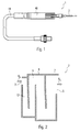
- Fig. 1 shows an isometric view of a cryosurgical instrument according to the present application.
- the instrument 1 consists of a cryoprobe holder 46 and a cryoprobe 2 which can be used therein, which according to the invention can be cooled by a configuration of a line system described in detail below in such a way that cryosurgical operations can be performed therewith.
- the cryosurgical device is equipped with gas supply means 44 which allow connection to a gas reservoir (not shown) or similar gas supply.
- Fig. 2 is a schematic representation of a first embodiment of the cryoprobe 2 can be seen.
- it is essentially designed as a cryoprobe surface which has a substantially flat, meandering line system 8 through which a cooling gas flows in a flow direction R S.
- the line system 8 is designed such that it has a widening over the flow path along the flow direction R S line cross-section and thus forms an expansion channel 12.
- the cooling gas flowing in via the inlet 3 on its way through the expansion channel 12 to a drain 5 gradually relaxes and so cooled according to the Joule-Thomson effect.
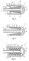
- Fig. 3-9 show further embodiments of the cryoprobe 2 according to the invention, wherein these are basically formed from a double-walled tube comprising an inner tube 19 and an outer tube 21.
- the inner tube 19 acts as an inlet 3, via which a cooling fluid can be passed through the cryoprobe 2.
- a cryoprobe tip 34 is arranged, which forms a connection between the inner channel 26 of the inner tube 19 and the outer channel 30 to form a Umlenkkanals 38, which is formed by the inner tube 19 and the outer tube 21.
- a modeling member 16 is arranged, which tapers in the flow direction R S such that a over a length l successively expanding expansion channel 12 is formed. Cooling fluid, which flows via the inlet 3 through the inner channel 26, from there via the deflection channel 38 into the expansion channel 12, there expands successively over the length l, so that it cools and thus over the heat-conductive outer wall 32 of the outer channel 30 comes to a cooling on the outside 7 of the cooling probe 2.
- cryoprobe 2 shown here is rotationally symmetrical in design from a double-walled tube with a uniformly thick outer wall 32 and a rotationally symmetrical, tapered hollow body as modeling component 12, uniform cooling occurs over the circumference of the cryoprobe 2.
- uniform cooling occurs over the circumference of the cryoprobe 2.
- Fig. 4 shows a third embodiment of the cryoprobe 2, again comprising an inner tube 19 and an outer tube 21, the channels 26 and 30 through a cryoprobe tip 34 and a resulting deflection channel 38 are in fluid communication with each other.
- a modeling member 16 to form a Expansion channel 12 used in the outer channel 30, a modeling member 16 to form a Expansion channel 12 used in the outer channel 30, a modeling member 16 to form a Expansion channel 12 used.
- the modeling component 16 is designed here as a rotationally symmetrical hollow cylinder with successively widening inner walls. In order to fix the hollow cylinder 16 in its position within the outer tube 21, this has Einsetznuten 29, which allow the perfect fit insertion.
- Fig. 5 shows a fourth embodiment of the Kryosondenspitze 2, again consisting of a double-walled tube 19, 21, in whose outer channel 30 to form the expansion channel 12, a modeling member 16 is inserted.
- this modeling component 16 comprises on a tapering wall 23 an external thread 22 which can be screwed into an internal thread 20 formed on the inner wall 28 of the outer tube 21.
- the cooling effect on the outside 7 can additionally be influenced here.
- Fig. 6 shows a fifth embodiment of the cryoprobe 2.
- the modeling member 16 is formed as a widening hollow cylinder having an internal thread 20 which is so complementary to an external thread 22 of the inner tube 18, that the modeling member 16 on the tube 19 with the formation of a helically encircling expansion channel 12 in the thread 24 of the two complementary threads 20, 22 can be screwed.
- this embodiment of the cryoprobe 2 comprises a cryoprobe tip 34, which can be screwed onto a free end 36 of the double-walled tube 19, 21 via a threaded region 35 in such a way that the size of the deflection channel 38 formed by the cryoprobe tip 34 can be screwed out or in through it the cryoprobe tip 34 is customizable.
- Fig. 7 shows a sixth embodiment of the cryoprobe 2, again comprising a double-walled tube 19, 21, wherein the inner tube 19 as the inlet 3 and the outer tube 21 and the inner tube formed between inner tube 19 and outer tube 21 30 functions as a return 5.
- a modeling component 16 is used to form an expansion channel 12, which has an external thread 22.
- the tube 21 has a complementary internal thread 20, which is designed here as a so-called opposite to the flow direction R S extending tapered thread.
- R S extending tapered thread.
- Fig. 8 shows a seventh embodiment of the cryoprobe 2, in which between a functioning as an inlet 3 inner tube 19 and an outer tube 21 on both walls 28, 32 of the tubes 19, 21 a helically extending around the inner tube 19 modeling component 16, in this case a Wire, is wound, so that between the individual windings 42, 42 'and the respective walls 28, 32 forms an expansion channel 12, which also extends again successively widening, around the inner tube 19 helically.
- a cooling fluid flowing in via the inner tube 19 or the inlet 3 in the flow direction R S then again enters this helical expansion channel 12 via a circulation channel 38, where it gradually relaxes and cools due to the successively increasing cross-section.
- the modeling component 16 or the wire can be both a component wound up independently on the inner tube 19 and a component formed integrally with this and / or the outer tube 21.
- Fig. 9 shows an eighth embodiment of the cryoprobe 2 according to the invention, which operates on the same principle, as the embodiment of Fig. 8 .
- the modeling element 16 embodied as a wire
- a corresponding notches 43 are arranged on the outer wall 32 of the outer tube 21 so that the resulting bulge 45 presses against the inner tube 19 in a fluid-tight manner. Since the notch 43 is helically and with increasing pitch applied to the outer tube 21, results between the individual turns of the notch 43 and the bulge 45 is a circumferential, successively expanding expansion channel 12 through which the gas flows along and under gradual cooling relaxed.
- FIG. 10 shows Fig. 10 in which the indentations 43 or protrusions 45 are arranged on the inner tube 19, so that the bulges 45 create a fluid-tight seal with the outer tube 21 or its wall 32, forming a corresponding expansion channel 12.
Landscapes
- Health & Medical Sciences (AREA)
- Surgery (AREA)
- Life Sciences & Earth Sciences (AREA)
- Nuclear Medicine, Radiotherapy & Molecular Imaging (AREA)
- Medical Informatics (AREA)
- Engineering & Computer Science (AREA)
- Biomedical Technology (AREA)
- Heart & Thoracic Surgery (AREA)
- Otolaryngology (AREA)
- Molecular Biology (AREA)
- Animal Behavior & Ethology (AREA)
- General Health & Medical Sciences (AREA)
- Public Health (AREA)
- Veterinary Medicine (AREA)
- Sampling And Sample Adjustment (AREA)
- Surgical Instruments (AREA)
- Thermotherapy And Cooling Therapy Devices (AREA)
Description
Vorliegende Erfindung betrifft ein kryochirurgisches Instrument, umfassend eine Kryosonde mit einem von einem komprimierten Kühlfluid, insbesondere Kühlgas durchströmten Leitungssystem, zum Abkühlen wenigstens eines Teils der Kryosonde.The present invention relates to a cryosurgical instrument, comprising a cryoprobe with a flow of a compressed cooling fluid, in particular cooling gas line system for cooling at least a portion of the cryoprobe.
In der Kryochirurgie wird die gezielte, kontrollierte Kälteanwendung zur Devitalisierung von biologischem Gewebe eingesetzt. Insbesondere mit flexiblen Sonden werden zudem Fremdkörper aus Körperhöhlen durch Festfrieren an der Kryosonde bzw. an einem Sondenkopf extrahiert, so z.B. verschluckte und dabei versehentlich eingeatmete Fremdkörper, die aus den Atemwegen entfernt werden müssen. Die Kryochirurgie eignet sich aber auch zur Gewinnung von Gewebeproben (Biopsie). Dabei friert ein bestimmter Gewebebereich, die Gewebeprobe, an den Sondenkopf an, und kann nach dem Abtrennen von umliegendem Gewebe einer Untersuchung zugänglich gemacht werden.In cryosurgery, the targeted, controlled application of cold is used for the devitalization of biological tissue. In particular, with flexible probes, foreign bodies are extracted from body cavities by freezing on the cryoprobe or on a probe head, e.g. swallowed and thereby inadvertently inhaled foreign bodies, which must be removed from the airways. Cryosurgery is also suitable for obtaining tissue samples (biopsy). In this case, a certain area of tissue, the tissue sample, freezes to the probe head, and after removal of surrounding tissue can be made accessible to an examination.
Um in der Chirurgie tiefzufrieren, gibt es verschiedene Möglichkeiten. Eine stützt sich auf den Joule-Thomson-Effekt: die Atome bzw. Moleküle eines sich expandierenden Fluides und insbesondere Gases unterhalb der Inversionstemperatur arbeiten gegen die gegenseitige Anziehung an, so dass das Gas an innerer Energie verliert. Es kühlt ab. Als expandierendes Fluid bzw. Gas - im Folgenden Kühlfluid bzw. Kühlgas genannt - werden üblicherweise CO2 oder N2O eingesetzt.To freeze in surgery, there are several options. One is based on the Joule-Thomson effect: the atoms or molecules of an expanding fluid, and in particular gas below the inversion temperature, work against the mutual attraction, so that the gas loses its internal energy. It cools down. As expanding fluid or gas - hereinafter referred to as cooling fluid or cooling gas - usually CO 2 or N 2 O are used.
Kryochirurgische Instrumente der eben beschriebenen Art verfügen üblicherweise über eine Sonde, die an das zu behandelnde Gewebe verbracht werden kann, ferner über Gasleitungseinrichtungen, welche die Sonden durchsetzen und innerhalb der Sonden das Arbeitsgas in das Innenvolumen der Sonden entlassen, wo es expandiert und in Folge dessen die Sonde abkühlt. Da diese vorzugsweise aus thermisch leitfähigem Material gefertigt ist, ist ein Ableiten der Gewebewärme über die Sonde und damit eine Kühlwirkung gewährleistet.Cryosurgical instruments of the type just described typically have a probe which can be delivered to the tissue to be treated, gas supply means which pass the probes and within the probes release the working gas into the interior volume of the probes where it expands and consequently the probe cools down. Since these are preferably made of thermally conductive material is manufactured, a derivation of the tissue heat on the probe and thus ensures a cooling effect.
Bei Kryosonden, bei denen die Kühlwirkung wie oben beschrieben durch Entspannung komprimierter Gase erzeugt wird, besteht häufig die Anforderung, eine größere Oberfläche gleichmäßig oder nach einem bestimmten Temperaturprofil zu kühlen. Beispielsweise soll eine Kryosonde von 2 mm Durchmesser über eine Länge von 50 mm gleichmäßig gekühlt werden.In cryoprobes in which the cooling effect is generated by relaxation of compressed gases as described above, there is often the requirement to cool a larger surface evenly or after a certain temperature profile. For example, a cryoprobe of 2 mm diameter should be uniformly cooled over a length of 50 mm.
Nach dem Stand der Technik werden in solchen Fällen mehrere Düsen im Inneren der Kryosonde verteilt angeordnet, um eine einigermaßen gleichmäßige Kühlung zu erreichen. Je größer die Anzahl der verwendeten Kühldüsen ist, desto gleichmäßiger stellt sich die resultierende Temperatur über die gewählte Länge ein. Bei dieser Vorgehensweise wird die benötigte Gasmenge auf mehrere Düsen verteilt. Die einzelnen Düsen sind folglich in ihrem Querschnitt sehr klein. Gleichzeitig wird die Herstellung aber überproportional aufwändig. Bei kleinen Düsen werden an die Geometrie enge Toleranzen gestellt, um ein gleich bleibendes Strömungsverhalten erzielen zu können. Kleinere Düsenquerschnitte sind auch prinzipiell anfälliger für Verstopfungen.In the prior art, in such cases, a plurality of nozzles are arranged distributed inside the cryoprobe in order to achieve a reasonably uniform cooling. The larger the number of cooling nozzles used, the more uniform the resulting temperature will be over the selected length. In this procedure, the required amount of gas is distributed over several nozzles. The individual nozzles are consequently very small in their cross-section. At the same time, however, the production becomes disproportionately expensive. For small nozzles, tight tolerances are imposed on the geometry in order to achieve a consistent flow behavior. Smaller nozzle cross sections are also prone to blockage in principle.
Problematisch hat sich bei kryochirurgischen Instrumenten nach dem Stand der Technik herausgestellt, dass die Realisierung eines im Wesentlichen gleich bleibenden Temperaturverlaufs oder eines vorbestimmten Temperaturverlaufs nur sehr schwer möglich ist. Darüber hinaus ist der Aufbau der herkömmlichen, aus dem Stand der Technik bekannten Kryosonden sehr aufwändig und kostenintensiv.In the case of cryosurgical instruments according to the prior art, it has proved to be problematic that the realization of a substantially constant temperature profile or a predetermined temperature profile is very difficult. In addition, the structure of the conventional, known from the prior art cryoprobes is very complex and expensive.
In
Der vorliegenden Erfindung liegt folglich die Aufgabe zu Grunde, ein kryochirurgisches Instrument der eingangs genannten Art dahin gehend weiter zu bilden, dass eine technisch einfacher zu realisierende und verbesserte, insbesondere gleichmäßigere Kühlung der Kryosonde erreichbar ist.The present invention is therefore based on the object to further develop a cryosurgical instrument of the type mentioned so that a technically easier to implement and improved, in particular more uniform cooling of the cryoprobe is achievable.
Diese Aufgabe wird durch ein kryochirurgisches Instrument gemäß Patentanspruch 1 gelöst.This object is achieved by a cryosurgical instrument according to claim 1.
Insbesondere wird diese Aufgabe durch ein kryochirurgisches Instrument, umfassend eine Kryosonde, mit einem von einem komprimierten Kühlfluid, insbesondere Kühlgas durchströmten Leitungssystem, zum Abkühlen wenigstens eines Teils der Kryosonde, dadurch gelöst, dass das Leitungssystem einen Expansionskanal aufweist, der einen sich in Strömungsrichtung über eine vorbestimmte Länge sukzessiv vergrößernden Leitungsquerschnitt derart aufweist, dass sich das komprimierte Kühlgas auf seinem Strömungsweg durch den Expansionskanal sukzessive über die vorbestimmte Länge hinweg bei gleichzeitiger Abkühlung wenigstens teilweise entspannt.In particular, this object is achieved by a cryosurgical instrument, comprising a cryoprobe, with a flowed through by a compressed cooling fluid, in particular cooling gas piping system for cooling at least a portion of the cryoprobe, characterized in that the conduit system has an expansion channel, a in the flow direction over a predetermined length has successively increasing line cross-section such that the compressed refrigerant gas on its flow path through the expansion channel successively over the predetermined length while cooling at least partially relaxed.
Der Kern der Erfindung liegt darin, einen über eine vorbestimmte Länge verlaufenden Kanal so zu gestalten, dass sein Querschnitt über diese Länge derart zunimmt, dass sich die Expansion des Gases über diese Länge des Kanals verteilt. Somit kommt es am Anfang des Kanals nur zu einer Teil-Expansion und somit nicht zur vollen Temperaturdifferenz, durch die sukzessive Expansion über die gesamte Länge jedoch zu einer Abkühlung über einen großen Bereich, wobei die erreichte Temperatur an der Außenseite der Sonde bzw. deren Verteilung u.a. von der jeweiligen Querschnittserweiterung und dem Wärmeübergangswiderstand zwischen dem Expansionskanal und der Außenseite der Kryosonde abhängt.The essence of the invention is to design a channel extending over a predetermined length such that its cross-section increases over that length such that the expansion of the gas is distributed over this length of the channel. Thus, at the beginning of the channel, only a partial expansion and thus not the full temperature difference, but by the successive expansion over the entire length to a cooling over a large area, wherein the temperature reached at the outside of the probe or their distribution among others depends on the respective cross-sectional widening and the heat transfer resistance between the expansion channel and the outside of the cryoprobe.
Vorzugsweise steht der Expansionskanal dabei über einen Wärmeleiter mit der Außenseite der Kryosonde in wärmeleitfähiger Verbindung. Als Wärmeleiter können entweder eigenständige Bauteile mit einem reduzierten Wärmeübergangswiderstand, oder aber entsprechende Hilfsmittel, wie Wärmeleitpasten etc. verwendet werden. Darüber hinaus ist es natürlich auch möglich, ein Gehäusebauteil der Kryosonde entsprechend als Wärmeleiter auszubilden und aus einem Material auszubilden, das eine optimale Wärmeüberleitung garantiert. Vorzugswiese ist der Expansionskanal möglichst nahe der Außenseite der Kryosonde bzw. nahe den Bereichen angeordnet, die gekühlt werden sollen.Preferably, the expansion channel is via a heat conductor to the outside of the cryoprobe in thermally conductive connection. As a heat conductor either independent components with a reduced heat transfer resistance, or appropriate tools, such as thermal compounds, etc. may be used. In addition, it is of course also possible to form a housing component of the cryoprobe accordingly as a heat conductor and form of a material that guarantees optimum heat transfer. Preferably, the expansion channel is arranged as close to the outside of the cryoprobe or near the areas to be cooled.
Vorzugsweise weist der Expansionskanal einen in Abhängigkeit eines Wärmeübergangswiderstandes des Wärmeleiters derart ausgebildeten Leitungsquerschnitt auf, dass sich auf der Außenseite der Kryosonde wenigstens über einen durch die oben genannte vorbestimmte Länge definierten Teilbereich eine vorbestimmte Temperaturverteilung und insbesondere eine gleich bleibende Temperatur einstellt. Das bedeutet, dass beispielsweise in sehr dicken Wandbereichen zwischen Expansionskanal und Außenseite bzw. einem zu kühlendem Bereich der Expansionskanal entsprechend stark erweitert ausgebildet wird, um hier eine besonders effektive Expansion und somit Abkühlung zu erzielen. Auch ist es natürlich möglich, in Bereichen auf der Außenseite der Kryosonde, bei denen eine sehr starke Abkühlung gewünscht ist, entsprechende Anpassungen am Expansionskanal vorzunehmen. Durch eine gezielte Anpassung des Querschnitts des Expansionskanals kann so, unter Beachtung beispielsweise der vorhandenen Wanddicken zur Außenseite, der Strömungsgeschwindigkeit etc., eine gleichmäßige oder jede andere gewünschte Temperaturverteilung auf der Außenseite der Kryosonde erreicht werden.Preferably, the expansion channel has a line cross-section formed in dependence on a heat transfer resistance of the heat conductor such that a predetermined temperature distribution and in particular a constant temperature are established on the outside of the cryoprobe at least over a partial area defined by the above-mentioned predetermined length. That means, for example In very thick wall regions between the expansion channel and the outside or a region to be cooled of the expansion channel is designed to be correspondingly greatly expanded in order to achieve a particularly effective expansion and thus cooling. Also, it is of course possible to make appropriate adjustments to the expansion channel in areas on the outside of the cryoprobe, where a very strong cooling is desired. By a targeted adaptation of the cross section of the expansion channel can thus be achieved, taking into account, for example, the existing wall thicknesses to the outside, the flow rate, etc., a uniform or any other desired temperature distribution on the outside of the cryoprobe.
Vorzugsweise ist der Expansionskanal derart ausgebildet, dass das Kühlgas in einer turbulenten Strömung strömt. Hier von Bedeutung ist u.a. natürlich der Strömungswiderstand im Expansionskanal, der Expansionskanalquerschnitt und darüber hinaus aber auch der Kühlfluiddruck, der insbesondere durch eine externe Kühlfluidversorgung bereitgestellt wird. Der Vorteil der turbulenten Strömung im Expansionskanal ist, dass es zu einer sehr effektiven Wärmeableitung und somit zu einer verbesserten Kühlung der Außenseite der Kryosonde kommt.Preferably, the expansion channel is formed such that the cooling gas flows in a turbulent flow. Of importance here is u.a. of course, the flow resistance in the expansion channel, the expansion channel cross-section and beyond but also the cooling fluid pressure, which is provided in particular by an external cooling fluid supply. The advantage of the turbulent flow in the expansion channel is that it leads to a very effective heat dissipation and thus to an improved cooling of the outside of the cryoprobe.
Vorzugsweise ist in wenigstens einem Teilbereich des Leitungssystems zur Bildung des Expansionskanals mindestens ein insbesondere sich in Strömungsrichtung verjüngendes/erweiterndes Modellierungsbauteil derart angeordnet, dass sich der resultierende Leitungsquerschnitt in Strömungsrichtung sukzessive vergrößert. Ist das Leitungssystem ein von Seitenwänden begrenzter Kanal, so kann das Modellierungsbauteil als ein sich in Strömungsrichtung verjüngendes insbesondere keilförmiges Bauteil an wenigstens einer dieser Seitenwände angeordnet werden, wodurch sich eben ein solcher erweiternder Expansionskanal ergibt, durch den das Kühlfluid bei gleichzeitiger sukzessiver Entspannung und Abkühlung strömen kann. An Stelle des zuvor erwähnten sich verjüngenden, keilförmigen Bauteils ist es auch möglich, ein Modellierungsbauteil in Form eines Hohlkörpers zu verwenden, beispielsweise ein Bauteil mit einer im Wesentlichen zentrischen Bohrung, dessen Bohrungswandung sich in Strömungsrichtung sukzessive erweitert, was ebenfalls zu einem sich erweiternden Expansionskanal führt.Preferably, in at least one subregion of the conduit system for forming the expansion channel, at least one modeling component, in particular tapering / widening in the direction of flow, is arranged such that the resulting conduit cross-section successively increases in the flow direction. If the conduit system is a channel bounded by side walls, then the modeling component can be arranged as a wedge-shaped component tapering in the flow direction on at least one of these side walls, thus resulting in such an expanding expansion channel through which the cooling fluid flows with simultaneous successive expansion and cooling can. Instead of the aforementioned tapered, wedge-shaped component, it is also possible to use a modeling component in the form of a hollow body, for example a component having a substantially centric bore whose bore wall successively widens in the flow direction, which also leads to a widening expansion channel ,
Vorzugsweise wird der Expansionskanal durch ein Rohr und ein Modellierungsbauteil gebildet, das als ein sich kegelstumpf oder dergleichen rotationssymmetrisches, sich verjüngendes Bauteil in das Rohr eingesetzt ist. Je nach gewünschter Temperaturverteilung an der Außenseite der Kryosonde kann also auch hier das Modellierungsbauteil in seiner Form verändert und somit direkt auf die Kühlwirkung Einfluss genommen werden. In diesem Zusammenhang ist es natürlich auch möglich, in das Rohr ein Modellierungsbauteil in Form eines Hohlkörpers einzusetzen, dessen Hohlkörperwandungen in Strömungsrichtung sukzessive erweiternd ausgebildet sind, so dass sich ebenfalls ein erweiternder Expansionskanal ergibt. Dies entspricht im Wesentlichen der zuvor genannten Ausführungsform des im Kanal angeordneten, sich erweiternden Hohlkörperbauteils und insbesondere eines rotationssymmetrischen Hohlkörpers als Modellierungsbauteil.Preferably, the expansion channel is formed by a tube and a modeling member inserted into the tube as a frusto-conical or the like rotationally symmetric tapered component. Depending on the desired temperature distribution on the outside of the cryoprobe, therefore, the modeling component can also be changed in its shape and thus directly influenced by the cooling effect. In this context, it is of course also possible to use a modeling component in the form of a hollow body in the tube, the hollow body walls of which are designed to widen successively in the flow direction, so that a widening expansion channel also results. This essentially corresponds to the aforementioned embodiment of the hollow body component arranged in the channel and, in particular, of a rotationally symmetrical hollow body as a modeling component.
Vorzugsweise bildet das Rohr wenigstens teilweise ein Kryosondengehäuse der Kryosonde, wobei das Rohr vorzugsweise aus einem Material besteht, dass eine gute Wärmeleitfähigkeit aufweist. Eine solche Ausführung der Kryosonde erlaubt die sehr einfache und kostengünstige Herstellung der Kryosonde gemäß den zuvor genannten Bauformen.Preferably, the tube at least partially forms a cryoprobe housing of the cryoprobe, wherein the tube is preferably made of a material having a good thermal conductivity. Such an embodiment of the cryoprobe allows the very simple and cost-effective production of the cryoprobe according to the aforementioned designs.
Selbstverständlich ist es möglich, an Stelle der zuvor genannten sich verjüngenden oder erweiternden Modellierungsbauteile, entsprechend andere Modellierungsbauteile oder Modelierungsbauteilgruppen zu verwenden, um einen sich in Strömungsrichtung sukzessive vergrößernden Querschnitt des Leitungssystems und somit einen Expansionskanal zur Abkühlung der Außenseite der Kryosonde herzustellen.Of course, instead of the aforementioned tapering or expanding modeling components, it is possible to use correspondingly different modeling components or modeling component groups in order to produce a cross section of the conduit system which successively enlarges in the flow direction and thus an expansion channel for cooling the outside of the cryoprobe.
Das Rohr umfasst vorzugsweise ein Innengewinde, und das Modellierungsbauteil auf einer sich verjüngenden Wandung ein komplementäres Außengewinde, mit dem es in das Rohr unter Bildung eines sich in Strömungsrichtung sukzessive vergrößernden Expansionskanals im resultierenden Gewindegang einschraubbar ist. Dadurch, dass der Expansionskanal im Wesentlichen wendelförmig um das Modellierungsbauteil herumläuft, vergrößert sich der Expansionsweg und somit die zu erzielende maximale Kühlleistung. Darüber hinaus ermöglicht eine solche Ausführungsform die sehr viel flächendeckendere Kühlung der Kryosonde. Natürlich kann durch eine geeignete Wahl unterschiedlicher Gewindearten auch auf die resultierende Außentemperatur bzw. deren Verteilung Einfluss genommen werden.The tube preferably comprises an internal thread, and the modeling component on a tapered wall has a complementary external thread with which it can be screwed into the tube to form a successively enlarging expansion channel in the resulting thread in the flow direction. The fact that the expansion channel runs essentially helically around the modeling component increases the expansion path and thus the maximum cooling power to be achieved. In addition, such an embodiment allows much more widespread cooling of the cryoprobe. Of course, can be influenced by a suitable choice of different types of threads on the resulting outside temperature or their distribution.
Vorzugsweise umfasst das Rohr ein Innengewinde und das Modellierungsbauteil ein komplementäres Außengewinde, mit dem es in das Rohr unter Bildung des Expansionskanals im resultierenden Gewindegang einschraubbar ist, wobei nun das Außengewinde als ein in Strömungsrichtung verlaufendes kegeliges oder dergleichen Gewinde und/oder das Innengewinde als ein in entgegengesetzter Richtung verlaufendes kegeliges oder dergleichen Gewinde ausgebildet ist. Unter kegeliges Gewinde sind hier Gewinde zu verstehen, deren Gewindegangtiefe sukzessive zunimmt, ähnlich der Außengeometrie eines Kegels. Beim Einschrauben in ein komplementäres Außen- bzw. Innengewinde entsteht so ein in Strömungsrichtung im Querschnitt expandierender Expansionskanal.Preferably, the tube comprises an internal thread and the modeling member has a complementary external thread, with which it can be screwed into the tube to form the expansion channel in the resulting thread, now the external thread as a running in the flow direction conical or similar thread and / or the internal thread as a in opposite direction extending conical or similar thread is formed. Tapered threads here are threads whose thread pitch increases successively, similar to the external geometry of a cone. When screwed into a complementary external or internal thread so creates an expanding in the flow direction in cross-section expansion channel.
Anstelle der zuvor beschriebene Gewinde jeglicher Bauart, können natürlich auch vergleichbare Kanäle, Nuten etc. im Rohr- oder Modellierungsbauteil ausgebildet werden, um einen entsprechenden Expansionskanals zu bilden. Hier sind sämtliche aus dem Stand der Technik bekannte Verfahren Bildung von Strömungskanälen etc. anwendbar.Of course, instead of the previously described threads of any type, comparable channels, grooves, etc. may be formed in the tube or modeling component to form a corresponding expansion channel. Here are all known from the prior art method formation of flow channels, etc. applicable.
Vorzugsweise wird der Expansionskanal zwischen einem äußeren Rohr und einem darin verlaufenden inneren Rohr gebildet. Das hat zur Folge, dass durch das innere Rohr das wärmere Kühlfluid zugeführt werden kann, um im weiter außen gelegenen Expansionskanal zu expandieren und die Außenseite des äußeren Rohres effektiv zu kühlen. In diesem Zusammenhang kann dann das äußere Rohr als Kryosondengehäuse verwendet werden oder über einen entsprechenden Wärmeleiter mit einem solchen Gehäuse verbunden sein.Preferably, the expansion channel is formed between an outer tube and an inner tube extending therein. As a result, the warmer cooling fluid can be supplied through the inner tube to expand in the more outward expansion channel and to effectively cool the outside of the outer tube. In this connection, the outer tube can then be used as a cryoprobe housing or connected to such a housing via a corresponding heat conductor.
Zur Bildung des sich sukzessive erweiternden Expansionskanals im doppelwandigen Rohr können sämtliche zuvor bereits abgehandelten Möglichkeiten herangezogen werden, wobei das Modellierungsbauteil dann vorzugsweise in den Außenkanal einsetzbar oder darin integriert ausgebildet ist. In diesem Zusammenhang ist es auch möglich ein Hohlkörperbauteil als Modellierungsbauteil zu verwenden, wobei dessen Hohlkörperbereich als insbesondere mittig angeordneter Zulauf fungiert.To form the successively expanding expansion channel in the double-walled tube, all options already discussed above can be used, wherein the modeling component is then preferably designed for use in the outer channel or integrated therein. In this context, it is also possible to use a hollow body component as a modeling component, wherein the hollow body region acts as an inlet arranged in particular centrally.
Vorzugsweise umfasst die Kryosonde eine Kryosondenspitze, die an einem Rohrende des zuvor beschriebenen doppelwandigen Rohres angeordnet ist und das Innenrohr mit dem Expansionskanal unter Bildung eines Umlenkkanals in Fluidverbindung bringt. Auf diese Weise können das innere Rohr und das äußere Rohr bzw. der im äußeren Rohr gebildete Außenkanal zur Zu- und Ableitung des Kühlfluides insbesondere -gases verwendet werden. Die resultierende geometrische Außenform eines solchen Rohres entspricht einer Kanüle und somit einer für die Kryochirurgie sehr anwendungsfreundlichen Form.Preferably, the cryoprobe comprises a cryoprobe tip disposed at a tube end of the previously described double-walled tube and fluidly communicating the inner tube with the expansion channel to form a deflection channel. To this Way, the inner tube and the outer tube or the outer channel formed in the outer channel for supply and discharge of the cooling fluid in particular gas can be used. The resulting geometric outer shape of such a tube corresponds to a cannula and thus a very user-friendly form for cryosurgery.
Vorzugsweise ist die Kryosondenspitze derart am Rohrende angeordnet und insbesondere über eine Gewindeeinrichtung ein- und ausschraubbar, dass der Querschnitt des Umlenkkanals veränderbar und insbesondere an einen Einlaufbereich des Expansionskanals adaptierbar ist. Der Vorteil liegt darin, dass nun durch eine Adaption des Umlenkkanals auch im Spitzenbereich der Kryosonde auf eine mögliche Expansion des Kühlfluidgases Einfluss genommen werden kann.The cryoprobe tip is preferably arranged at the pipe end and can be screwed in and out, in particular via a threaded device, such that the cross section of the deflection channel can be changed and, in particular, adapted to an inlet region of the expansion channel. The advantage lies in the fact that an adaptation of the deflection channel, even in the tip region of the cryoprobe, can influence the possible expansion of the cooling fluid gas.
Vorzugsweise ist um das innere Rohr eines wie oben beschriebenen doppelwandig ausgeführten Rohres ein in Strömungsrichtung wendelförmig, mit ansteigender Steigung verlaufendes Modellierungsbauteil, insbesondere ein Draht angeordnet, der mit den Wandungen beider Rohre jeweils in fluiddichter Verbindung steht, so dass zwischen benachbarten Windungen und den Wandungen der Rohre ein wendelförmiger, im Querschnitt sukzessive zunehmender Expansionskanal gebildet wird. Natürlich kann auch durch die Wahl des verwendeten, umlaufenden Modellierungsbauteils auf die Geometrie und den Querschnitt des Expansionskanals Einfluss genommen werden. So ist es beispielsweise möglich, mit einem sich sukzessive verjüngenden Modellierungsbauteil, das mit einer gleichmäßigen Wendelsteigung auf das innere Rohr aufgebracht wird, einen sich sukzessive erweiternden Expansionskanal herzustellen.Preferably, around the inner tube of a double-walled tube as described above, a helically extending in the flow direction, with rising slope modeling component, in particular a wire is arranged, which is in fluid-tight communication with the walls of both tubes, so that between adjacent turns and the walls of the Tubes a helical, in cross-section successively increasing expansion channel is formed. Of course, the geometry and the cross-section of the expansion channel can also be influenced by the choice of the circulating modeling component used. It is thus possible, for example, to produce a successively expanding expansion channel with a successively tapered modeling component which is applied to the inner tube with a uniform helical pitch.
Vorzugsweise weist grundsätzlich das Modellierungsbauteil, insbesondere im nach Außen weisenden Bereich eine gute Wärmeleitfähigkeit auf, um eine effektive Kühlung der Außenseite bzw. der zu kühlenden Bereiche der Kryosonde sicherzustellen. Um eine effektive Abkühlung der Außenseite zu erzielen ist es zudem möglich, im nach innen weisen Bereich, also beispielsweise dem Bereich, der an den Zulauf mit dem "warmen" Kühlfluid vor seiner Entspannung grenzt, entsprechende Dämmschichten anzuordnen. Dies kann wieder durch die Verwendung entsprechender dämmender Zwischenschichten oder durch eine entsprechende Materialwahl des Modellierungsbauteils oder des inneren Rohres etc. erreicht werden.In principle, the modeling component, in particular in the region facing outward, preferably has a good thermal conductivity, in order to ensure effective cooling of the outside or the regions of the cryoprobe to be cooled. In order to achieve effective cooling of the outside, it is also possible to arrange appropriate insulating layers in the inwardly facing region, for example, the region adjacent to the inlet with the "warm" cooling fluid before its relaxation. This can be achieved again by the use of corresponding insulating intermediate layers or by an appropriate choice of material of the modeling component or the inner tube, etc.
Grundsätzlich ist es möglich, das wendelförmige Modellierungsbauteil auf das innere Rohr aufzuwickeln, oder aber auch in Form einer eigenständigen Wendel in den Zwischenraum zwischen Innenrohr und äußerem Rohr einzubringen und insbesondere einzudrehen.In principle, it is possible to wind the helical modeling component onto the inner tube, or else to introduce it in the form of an independent helix into the intermediate space between the inner tube and the outer tube and, in particular, to screw it in.
Vorzugsweise ist das Modellierungsbauteil integral am inneren Rohr und/oder am äußeren Rohr und insbesondere durch eine wendelförmige Einkerbung der jeweiligen Wandungen des Rohres gebildet, wobei in Strömungsrichtung die Steigung der wendelförmigen Einkerbung und/oder deren Breite zunimmt. Auch auf diese Weise kann also ein Expansionskanal geschaffen werden, der wendelförmig das innere Rohr umläuft und derart im Querschnitt erweitert ausgebildet ist, dass es zu einer sukzessiven Entspannung des Gases und somit zu einer Abkühlung über die gesamte Länge des Expansionskanals kommt. Natürlich ist es hier möglich, über entsprechende Querschnittsänderung über die Länge des Expansionskanals im Vergleich kältere und weniger kältere Bereiche zu schaffen, wenn dies nötig ist. Auch ist es natürlich möglich, die integral am inneren Rohr und/oder am äußeren Rohr ausgebildeten Modellierungsbauteile durch Ausfräsungen der benachbarten Gebiete auszubilden, die dann passgenau an der komplementären Rohrwand anstehen etc. Auch ist es möglich, an einem oder an beiden Rohren entsprechende Führungsnuten oder -einrichtungen anzuordnen, die das Einsetzten eines wendelförmigen Modellierungsbauteils erlauben. Auch können hier natürlich eine Mehrzahl an unterschiedlichen Nuten vorgesehen sein, um beispielsweise unterschiedliche Modellierungsbauteile einzufügen oder aber auch unterschiedliche Steigungen, Querschnittsänderungen etc. zu erzielen.Preferably, the modeling component is integrally formed on the inner tube and / or on the outer tube and in particular by a helical indentation of the respective walls of the tube, wherein increases in the flow direction, the slope of the helical indentation and / or the width thereof. Also in this way, therefore, an expansion channel can be created, which rotates helically around the inner tube and is formed so expanded in cross-section that it comes to a successive relaxation of the gas and thus to a cooling over the entire length of the expansion channel. Of course, it is possible to create relatively colder and less colder regions by appropriate cross-sectional change over the length of the expansion channel, if necessary. It is also possible, of course, for the modeling components formed integrally on the inner tube and / or on the outer tube to be formed by milling out the adjacent regions, which then fit precisely against the complementary tube wall, etc. It is also possible to use corresponding guide grooves or grooves on one or both tubes To arrange devices that allow the insertion of a helical modeling component. Of course, a plurality of different grooves can of course also be provided here in order, for example, to insert different modeling components or else to achieve different gradients, cross-sectional changes, etc.
Im Zusammenhang mit Modellierungsbauteilen, die in das Leitungssystem und insbesondere in den Außenkanal eines doppelwandigen Rohres einführbar sind, ist es auch denkbar, das Modellierungsbauteil derart flexibel auszubilden, dass der Expansionskanal nach Bedarf veränderbar ist. So kann beispielsweise durch das Einführen einer auf das Innenrohr passgenau aufsteckbaren elastischen Wendel mit in Strömungsrichtung ansteigendem Gewinde, die ebenfalls passgenau an der Wandung des Außenrohrs ansteht, durch ein Verschieben bzw. verdrehen der Wendel in Axialrichtung des Rohres die Querschnittsveränderung des Expansionskanals beeinflusst werden.In connection with modeling components, which are insertable into the pipe system and in particular into the outer channel of a double-walled pipe, it is also conceivable to design the modeling component so flexibly that the expansion channel can be changed as required. Thus, for example, by inserting a fitting on the inner tube elastic coil with increasing in the direction of flow thread, which also fits precisely on the wall of the outer tube, by a displacement or rotation of the helix in the axial direction of the tube, the cross-sectional change of the expansion channel can be influenced.
Eine Anpassung kann natürlich auch über mehrteilige Modellierungsbauteile erfolgen, die eine Veränderung des Querschnitts des Expansionskanals über seine Länge zulassen.Of course, an adaptation can also take place via multi-part modeling components which allow a change in the cross section of the expansion channel over its length.
Vorzugsweise ist diese Anpassung über einen Griff am Kryosondengerät oder eine externe Steuereinrichtung möglich, um auch während der Operation die Temperatur der Kryosonde regeln zu können. Hier sind sämtliche aus dem Stand der Technik bekannte Verfahren zur Steuerung eines chirurgischen Gerätes anwendbar.Preferably, this adjustment via a handle on Kryosondengerät or an external control device is possible in order to regulate the temperature of the cryoprobe during the operation can. Here are all known from the prior art method for controlling a surgical device applicable.
Weitere Ausführungsformen der Erfindung ergeben sich aus den Unteransprüchen.Further embodiments of the invention will become apparent from the dependent claims.
Im Folgenden wird die Erfindung anhand von acht Ausführungsbeispielen beschrieben, die durch die beiliegenden Zeichnungen näher erläutert sind. Hierbei zeigen:
- - Fig. 1
- eine schematische Darstellung des erfindungsgemäßen Kryochirurgiegerätes;
- - Fig. 2
- eine erste Ausführungsform einer Kryosonde des Kryochirurgiegerätes aus
Fig. 1 ; - - Fig. 3
- eine zweite Ausführungsform einer Kryosonde des Kryochirurgiegerätes aus
Fig. 1 ; - - Fig. 4
- eine dritte Ausführungsform einer Kryosonde des Kryochirurgiegerätes aus
Fig. 1 ; - - Fig. 5
- eine vierte Ausführungsform einer Kryosonde des Kryochirurgiegerätes aus
Fig. 1 ; - - Fig. 6
- eine fünfte Ausführungsform einer Kryosonde des Kryochirurgiegerätes aus
Fig. 1 ; - - Fig. 7
- eine sechste Ausführungsform einer Kryosonde des Kryochirurgiegerätes aus
Fig. 1 ; - - Fig. 8
- eine siebte Ausführungsform einer Kryosonde des Kryochirurgiegerätes aus
Fig. 1 ; - - Fig. 9
- eine achte Ausführungsform einer Kryosonde des Kryochirurgiegerätes aus
Fig. 1 ; und - - Fig. 10
- eine weitere Ausführungsform.
- - Fig. 1
- a schematic representation of the cryosurgical apparatus according to the invention;
- - Fig. 2
- a first embodiment of a cryoprobe of the cryosurgical unit from
Fig. 1 ; - - Fig. 3
- a second embodiment of a cryoprobe of the cryosurgical unit from
Fig. 1 ; - - Fig. 4
- a third embodiment of a cryoprobe of the cryosurgical unit from
Fig. 1 ; - - Fig. 5
- a fourth embodiment of a cryoprobe of the cryosurgical unit from
Fig. 1 ; - - Fig. 6
- a fifth embodiment of a cryoprobe of the cryosurgical unit from
Fig. 1 ; - - Fig. 7
- a sixth embodiment of a cryoprobe of the cryosurgical unit from
Fig. 1 ; - - Fig. 8
- a seventh embodiment of a cryoprobe of the cryosurgical unit from
Fig. 1 ; - - Fig. 9
- an eighth embodiment of a cryoprobe of the cryosurgical unit
Fig. 1 ; and - - Fig. 10
- another embodiment.
Im Folgenden werden für gleiche und gleich wirkende Bauteile dieselben Bezugszeichen verwendet.In the following, the same reference numerals are used for identical and equivalent components.
Das kryochirurgische Gerät ist mit Gaszuleitungseinrichtungen 44 ausgerüstet, die den Anschluss an ein Gasreservoir (nicht dargestellt) oder eine ähnliche Gasversorgung ermöglichen.The cryosurgical device is equipped with gas supply means 44 which allow connection to a gas reservoir (not shown) or similar gas supply.
In
Das Leitungssystem 8 ist dabei derart ausgebildet, dass es einen sich über den Strömungsweg entlang der Strömungsrichtung RS erweiternden Leitungsquerschnitt aufweist und so einen Expansionskanal 12 bildet. Das hat zur Folge, dass sich das über den Zulauf 3 einströmende Kühlgas auf seinem Weg durch den Expansionskanal 12 zu einem Ablauf 5 sukzessive entspannt und so gemäß dem Joule-Thomson-Effekt abkühlt. Durch eine entsprechend wärmeleitfähige Ausbildung der Kanalwandungen 9 des Leitungssystems 8 kann so eine Außenseite 7 der Kryosonde 2 effektiv gekühlt werden.The
Die
In diesem äußeren Kanal 30 ist ein Modellierungsbauteil 16 angeordnet, das sich in Strömungsrichtung RS derart verjüngt, dass sich ein über eine Länge l sukzessive erweiternder Expansionskanal 12 bildet. Kühlfluid, das über den Zulauf 3 durch den inneren Kanal 26, von dort über den Umlenkkanal 38 in den Expansionskanal 12 strömt, expandiert dort sukzessive über die Länge l, so dass es zu dessen Abkühlung und somit über die wärmeleitende äußere Wandung 32 des äußeren Kanals 30 zu einer Abkühlung auf der Außenseite 7 der Kühlsonde 2 kommt.In this
Da die hier abgebildete Kryosonde 2 rotationssymmetrisch aus einem doppelwandigen Rohr mit einer gleichbleibend dicken äußeren Wandung 32 und einem als Modellierungsbauteil 12 entsprechend rotationssymmetrischem, sich verjüngendem Hohlkörper ausgebildet ist, kommt es auch zu einer gleichmäßigen Abkühlung über den Umfang der Kryosonde 2. Natürlich ist es auch möglich, durch eine entsprechend veränderte Ausführung des Modellierungsbauteils 16 oder der Lage des inneren Rohres 19 relativ zum äußeren Rohr 21, eine ungleichmäßige Kühlung über den Umfang der Kryosonde 2 zu erzielen.Since the
Im Unterschied zu den zuvor beschriebenen Ausführungsformen umfasst dieses Modellierungsbauteil 16 auf einer sich verjüngenden Wandung 23 ein Außengewinde 22, das in ein an der inneren Wandung 28 des äußeren Rohres 21 ausgebildetes Innengewinde 20 einschraubbar ist.In contrast to the embodiments described above, this
Aufgrund der Ausbildung des Außengewindes 22 auf der geneigten bzw. sich verjüngenden Wandung 23 des Modellierungsbauteiles 16 ergibt sich beim Einschrauben dieses Bauteils in das Innengewinde 20 am äußeren Rohr 21 ein sich sukzessive erweiternder Gewindegang 24, der als Expansionskanal 12 fungiert. Dieser steht an einem Einlaufbereich 40 mit einem ebenfalls wieder durch eine Kryosondenspitze 34 gebildeten Umlenkkanal 38 in Fluidverbindung, so dass Kühlfluid über das innere Rohr 19 in Strömungsrichtung RS expandierend durch den sich wendelförmig umlaufend erstreckenden Expansionskanal 12 strömen kann, um die Außenseite 7 der Kryosonde 2 abzukühlen.Due to the formation of the
Durch eine geeignete Wahl der Gewindesteigung und der Tiefe des jeweiligen Gewindegangs 24 kann hier zusätzlich auf die Kühlwirkung auf der Außenseite 7 Einfluss genommen werden.By a suitable choice of the thread pitch and the depth of the
Darüber hinaus umfasst diese Ausführungsform der Kryosonde 2 eine Kryosondenspitze 34, die über einen Gewindebereich 35 auf ein freies Ende 36 des doppelwandigen Rohres 19, 21 derart aufschraubbar ist, dass die Größe des durch die Kryosondenspitze 34 gebildeten Umlenkkanals 38 durch ein heraus- bzw. hereinschrauben der Kryosondenspitze 34 anpassbar ist.In addition, this embodiment of the
Im äußeren Kanal 30 ist zur Bildung eines Expansionskanals 12 ein Modellierungsbauteil 16 eingesetzt, das ein Außengewinde 22 aufweist. Das Rohr 21 weist ein dazu komplementäres Innengewinde 20 auf, das hier als ein so genanntes entgegen der Strömungsrichtung RS verlaufendes kegeliges Gewinde ausgebildet ist. Das bedeutet, dass sich der Querschnitt des Gewindegangs 24 und somit der Expansionskanal 12 in Strömungsrichtung aufgrund dieses entgegen der Strömungsrichtung kegeliges Gewinde sukzessive vergrößert und so, wie schon in den zuvor beschriebenen Ausführungsformen, sukzessive erweitert. Natürlich wäre es hier auch möglich, an Stelle der gleichmäßigen Gewindesteigung eine zunehmende Gewindesteigung auszubilden oder aber auch das Modellierungsbauteil 16 entsprechend zu verjüngen, um beispielsweise eine in Richtung des freien Endes 36 der Kryosonde 2 stärker werdende Abkühlung der Außenseite 7 zu erzielen.In the
Natürlich ist es zudem möglich, statt dessen oder aber auch ergänzend an Stelle des entgegen der Strömungsrichtung RS kegelig verlaufenden Gewindes 20 im Außenrohr 21 ein in Strömungsrichtung verlaufendes kegeliges Gewinde 22 im Modellierungsbauteil 16 anzuordnen.Of course, it is also possible, instead or in addition to instead of the counter to the flow direction R S tapered
Eine ähnliche Ausführungsform zeigt
Grundsätzlich sei angemerkt, dass natürlich neben den hier gezeigten Ausführungsformen des Modellierungsbauteils sämtliche Modellierungsbauteile verwendet werden können, die die Ausbildung eines sich sukzessive im Querschnitt vergrößernden Expansionskanals ermöglichen. Hier ist natürlich auch die Ausführung des Rohres bzw. des äußeren Rohres 21 als sich kegelig erweiterndes Rohr etc. denkbar.In principle, it should be noted that, of course, in addition to the embodiments of the modeling component shown here, all modeling components can be used which enable the formation of an expansion channel which successively enlarges in cross-section. Here, of course, the execution of the tube or the
Im Zusammenhang mit umlaufenden Gewindegängen zur Bildung des Expansionskanals können natürlich auch Doppel- und Mehrfachwendeln oder dergleichen mehrere sich insbesondere konzentrisch windende Gänge oder Kanäle etc. angewendet werden.Of course, in connection with circumferential threads for forming the expansion channel, it is also possible to use double and multiple helixes or the like several, in particular concentrically helical gears or channels, etc.
- 11
- Kryochirurgisches InstrumentCryosurgical instrument
- 22
- Kryosondecryoprobe
- 33
- ZulaufIntake
- 44
- Kühlgascooling gas
- 55
- Ablaufprocedure
- 77
- Außenseiteoutside
- 88th
- Leitungssystemline system
- 99
- Kanalwandungchannel wall
- 1212
- Expansionskanalexpansion channel
- 1414
- Wärmeleiterheat conductor
- 1616
- Modellierungsbauteilmodeling component
- 1818
- Rohrpipe
- 1919
- inneres Rohrinner tube
- 2020
- Innengewindeinner thread
- 2121
- äußeres Rohrouter tube
- 2222
- Außengewindeexternal thread
- 2323
- verjüngende Wandungtapered wall
- 2424
- Gewindegangthread
- 2626
- innerer Kanalinner channel
- 2828
- innere Wandunginner wall
- 3030
- äußerer Kanalouter channel
- 3232
- äußere Wandungouter wall
- 3434
- Kryosondenspitzecryoprobe
- 3636
- freies Ende bzw. Rohrendefree end or pipe end
- 3838
- Umlenkkanaldiversion channel
- 4040
- Einlaufbereichintake area
- 4242
- Windungconvolution
- 4343
- Einkerbungnotch
- 4444
- GasleitungseinrichtungGas line device
- 4545
- Ausbuchtungbulge
- 4646
- KryosondenhalterKryosondenhalter
Claims (15)
- Cryosurgical instrument, comprising a cryoprobe with a cryoprobe housing, with a conduit system (8) through which a compressed cooling fluid can flow for cooling at least part of the cryoprobe (2), further comprising an outer tube (21) and, extending within the latter, an inner tube (19) for delivering the cooling fluid, wherein the outer tube (21) forms the cryoprobe housing or is connected to the cryoprobe housing via a heat conductor (14), characterized in that the conduit system (8) has an expansion channel (12) with a conduit cross section that gradually increases in size in the flow direction (RS) over a predetermined length, in such a way that the compressed cooling gas, on its flow path through the expansion channel (12), gradually decompresses, at least in part, along the predetermined length and at the same time cools down, wherein the expansion channel (12) is arranged in the area of the areas of the cryoprobe (2) that are to be cooled and is formed between the outer tube (21) and the inner tube (19) extending within the latter.
- Cryosurgical instrument according to Claim 1, characterized in that the expansion channel (12)
is connected in a thermally conductive manner to the outside (7) of the cryoprobe (2) via a heat conductor (14). - Cryosurgical instrument according to Claim 2, characterized in that the expansion channel (12) has a conduit cross section designed as a function of a heat transfer resistance of the heat conductor (32) in such a way that, on the outside (7) of the cryoprobe (2), a predetermined temperature distribution is established at least over a partial area defined by the predetermined length.
- Cryosurgical instrument according to one of the preceding claims, characterized in that the expansion channel (12) is configured in such a way that the cooling gas flows in a turbulent flow.
- Cryosurgical instrument according to one of the preceding claims, characterized in that, in order to form the expansion channel (12), at least one modelling component (16) that tapers/widens in the flow direction is arranged in at least a partial area of the conduit system (8), in such a way that the resulting conduit cross section gradually increases in size in the flow direction (RS).
- Cryosurgical instrument according to Claim 5, characterized in that the expansion channel (12) is formed by a tube (21) and a modelling component (16) that is inserted into the tube (21) as a frustoconical or similarly rotationally symmetrical component tapering in the flow direction (RS).
- Cryosurgical instrument according to Claim 5, characterized in that the expansion channel (12) is formed by a tube (21) and a modelling component (16) that is inserted into the tube (21) as a rotationally symmetrical hollow-body component that widens in the flow direction (RS).
- Cryosurgical instrument according to Claim 6 or 7, characterized in that the tube (21) at least partially forms a cryoprobe housing of the cryoprobe (2).
- Cryosurgical instrument according to one of Claims 6 to 8, characterized in that the tube (21) has an internal thread (20) and the modelling component (16) has, on a tapering wall (23), a complementary external thread (22) with which it can be screwed into the tube (21) so as to form, in the resulting thread turn (24), an expansion channel (12) that gradually increases in size in the flow direction (RS).
- Cryosurgical instrument according to one of Claims 6 to 9, characterized in that the tube (21) has an internal thread (20) and the modelling component (16) has a complementary external thread (22) with which it can be screwed into the tube (21) so as to form the expansion channel (12) in the resulting thread turn (24), wherein the external thread (22) is configured as a conical or similar thread running in the flow direction (RS) and/or the internal thread (20) is configured as a conical or similar thread running in the opposite direction.
- Cryosurgical instrument according to one of the preceding claims, characterized by a cryoprobe tip (34), which is arranged on one tube end (36) and brings the inner tube (19) into fluid communication with the expansion channel (12) by forming a deflection channel (38).
- Cryosurgical instrument according to Claim 11, characterized in that the cryoprobe tip (34) is arranged on the tube end (36) in such a way that the cross section of the deflection channel (38) can be modified.
- Cryosurgical instrument according to one of the preceding claims, characterized in that the inner tube (19) has an external thread (22) and the modelling component (16) is configured as a rotationally symmetrical hollow body which gradually widens and which, on its inner hollow-body wall, has an internal thread (20) with which it can be screwed onto the external thread (22) of the inner tube (19) so as to form the expansion channel (12) in the thread turn (24).
- Cryosurgical instrument according to one of the preceding claims, characterized in that a modelling component (16) extending in the shape of a helix and with an increasing pitch in the flow direction (RS) is arranged around the inner tube (19) and is in fluid-tight connection with the walls (28, 32) of both tubes (19, 21), respectively, such that a helical expansion channel (12) increasing gradually in cross section is formed between adjacent windings (42, 42') and the walls (26, 32).
- Cryosurgical instrument according to Claim 14, characterized in that the modelling component (16) is formed integrally on the inner tube (19) and/or on the outer tube (32) by a helical indentation (43) of the respective wall (28, 32) of the tube (19, 21), wherein the pitch of the helical indentation (43) and/or its width (b) increases in the flow direction (RS).
Priority Applications (1)
| Application Number | Priority Date | Filing Date | Title |
|---|---|---|---|
| PL09711752T PL2257235T3 (en) | 2008-02-21 | 2009-02-11 | Cryosurgical instrument |
Applications Claiming Priority (2)
| Application Number | Priority Date | Filing Date | Title |
|---|---|---|---|
| DE102008010477A DE102008010477A1 (en) | 2008-02-21 | 2008-02-21 | Cryosurgical instrument |
| PCT/EP2009/000956 WO2009103448A1 (en) | 2008-02-21 | 2009-02-11 | Cryosurgical instrument |
Publications (2)
| Publication Number | Publication Date |
|---|---|
| EP2257235A1 EP2257235A1 (en) | 2010-12-08 |
| EP2257235B1 true EP2257235B1 (en) | 2015-04-29 |
Family
ID=40668324
Family Applications (1)
| Application Number | Title | Priority Date | Filing Date |
|---|---|---|---|
| EP09711752.7A Not-in-force EP2257235B1 (en) | 2008-02-21 | 2009-02-11 | Cryosurgical instrument |
Country Status (7)
| Country | Link |
|---|---|
| US (1) | US8939968B2 (en) |
| EP (1) | EP2257235B1 (en) |
| JP (2) | JP2011514188A (en) |
| CN (1) | CN101969872B (en) |
| DE (1) | DE102008010477A1 (en) |
| PL (1) | PL2257235T3 (en) |
| WO (1) | WO2009103448A1 (en) |
Families Citing this family (10)
| Publication number | Priority date | Publication date | Assignee | Title |
|---|---|---|---|---|
| CN103402449B (en) * | 2011-03-09 | 2016-08-10 | 艾斯酷瑞医药有限公司 | There is the Cryobiopsy probe of changed course stream |
| US10390871B2 (en) * | 2015-02-20 | 2019-08-27 | Galil Medical Inc. | Cryoneedle |
| RU167325U1 (en) * | 2016-04-13 | 2017-01-10 | Общество с ограниченной ответственностью инновационное предприятие 'Биостандарт" (ООО ИП "Биостандарт") | DEVICE FOR LOCAL CRYOTHERAPY |
| CN106052179A (en) * | 2016-06-08 | 2016-10-26 | 西安交通大学 | Self-adjusting type throttling refrigerator for corrugated tube |
| US11648047B2 (en) | 2017-10-06 | 2023-05-16 | Vive Scientific, Llc | System and method to treat obstructive sleep apnea |
| CN116919565A (en) | 2017-11-13 | 2023-10-24 | 生物相容英国有限公司 | Cryoablation system with magnetic resonance imaging detection |
| US20200305948A1 (en) * | 2019-03-25 | 2020-10-01 | Biocompatibles Uk Limited | Cryoprobe |
| EP3769706A1 (en) | 2019-07-23 | 2021-01-27 | Erbe Elektromedizin GmbH | Cryoprobe |
| CN112213069B (en) * | 2020-10-12 | 2022-06-10 | 中国空气动力研究与发展中心超高速空气动力研究所 | Flow field calibration and measurement bent frame with cooling structure for hypersonic high-temperature wind tunnel |
| CN113143580B (en) * | 2021-04-07 | 2022-11-18 | 深圳市眼科医院 | Pen type delicate freezing device adopting Freon |
Citations (1)
| Publication number | Priority date | Publication date | Assignee | Title |
|---|---|---|---|---|
| US20030023288A1 (en) * | 1999-02-09 | 2003-01-30 | Michael Magers | Method and device for patient temperature control employing optimized rewarming |
Family Cites Families (12)
| Publication number | Priority date | Publication date | Assignee | Title |
|---|---|---|---|---|
| US3613689A (en) * | 1970-01-13 | 1971-10-19 | Frigitronics Of Conn Inc | Cryosurgical apparatus |
| DE2831199C3 (en) * | 1978-07-15 | 1981-01-08 | Erbe Elektromedizin Gmbh & Co Kg, 7400 Tuebingen | Cryosurgical device |
| US5254116A (en) * | 1991-09-06 | 1993-10-19 | Cryomedical Sciences, Inc. | Cryosurgical instrument with vent holes and method using same |
| GB2283678B (en) * | 1993-11-09 | 1998-06-03 | Spembly Medical Ltd | Cryosurgical catheter probe |
| US5901783A (en) * | 1995-10-12 | 1999-05-11 | Croyogen, Inc. | Cryogenic heat exchanger |
| US7591814B2 (en) * | 1997-02-27 | 2009-09-22 | Cryocath Technologies Inc. | Extended treatment zone catheter |
| US6669689B2 (en) * | 1997-02-27 | 2003-12-30 | Cryocath Technologies Inc. | Cryosurgical catheter |
| GB2336781B (en) * | 1998-04-30 | 2001-03-07 | Spembly Medical Ltd | Cryosurgical apparatus |
| US6270493B1 (en) * | 1999-07-19 | 2001-08-07 | Cryocath Technologies, Inc. | Cryoablation structure |
| EP1208058B1 (en) * | 1999-08-31 | 2004-10-27 | The Coca-Cola Company | Heat exchanger for beverage dispenser |
| US6858025B2 (en) * | 2002-08-06 | 2005-02-22 | Medically Advanced Designs, Llc | Cryo-surgical apparatus and method of use |
| US7160291B2 (en) | 2003-06-25 | 2007-01-09 | Endocare, Inc. | Detachable cryosurgical probe |
-
2008
- 2008-02-21 DE DE102008010477A patent/DE102008010477A1/en not_active Withdrawn
-
2009
- 2009-02-11 WO PCT/EP2009/000956 patent/WO2009103448A1/en active Application Filing
- 2009-02-11 JP JP2010547082A patent/JP2011514188A/en active Pending
- 2009-02-11 PL PL09711752T patent/PL2257235T3/en unknown
- 2009-02-11 US US12/918,587 patent/US8939968B2/en not_active Expired - Fee Related
- 2009-02-11 EP EP09711752.7A patent/EP2257235B1/en not_active Not-in-force
- 2009-02-11 CN CN2009801058401A patent/CN101969872B/en not_active Expired - Fee Related
-
2013
- 2013-12-19 JP JP2013262668A patent/JP5925754B2/en not_active Expired - Fee Related
Patent Citations (1)
| Publication number | Priority date | Publication date | Assignee | Title |
|---|---|---|---|---|
| US20030023288A1 (en) * | 1999-02-09 | 2003-01-30 | Michael Magers | Method and device for patient temperature control employing optimized rewarming |
Also Published As
| Publication number | Publication date |
|---|---|
| CN101969872A (en) | 2011-02-09 |
| JP2011514188A (en) | 2011-05-06 |
| JP5925754B2 (en) | 2016-05-25 |
| DE102008010477A1 (en) | 2009-09-03 |
| US20110022040A1 (en) | 2011-01-27 |
| WO2009103448A1 (en) | 2009-08-27 |
| CN101969872B (en) | 2013-09-25 |
| JP2014131734A (en) | 2014-07-17 |
| US8939968B2 (en) | 2015-01-27 |
| EP2257235A1 (en) | 2010-12-08 |
| PL2257235T3 (en) | 2015-10-30 |
Similar Documents
| Publication | Publication Date | Title |
|---|---|---|
| EP2257235B1 (en) | Cryosurgical instrument | |
| DE2831199C3 (en) | Cryosurgical device | |
| EP2415581B1 (en) | Injection moulding nozzle | |
| DE102008024946B4 (en) | Cryosurgical instrument for obtaining a tissue sample | |
| WO2014184238A1 (en) | Medical catheter for hypothermic treatment, treatment system with such a catheter, and production method | |
| EP2664438B1 (en) | Nozzle piece for an injection moulding nozzle, injection moulding nozzle and injection moulding tool | |
| EP3788974A1 (en) | Ablation probe | |
| DE202007006682U1 (en) | Geothermal power probe e.g. for using geothermal power for heating purposes, made from plastic and has advance and return channel arranged coaxially with interior pipe arranged loosely centrically and lengthwise adjustable | |
| EP3437579B1 (en) | Cryosurgical instrument | |
| DE3046471A1 (en) | Heated nozzle core for injection moulding machine - has helical heating element laid in groove on outer face of core | |
| WO2015044142A1 (en) | Geothermal probe with mixing elements | |
| DE102011080315B4 (en) | Heating device with temperature sensor | |
| EP1646323B1 (en) | Surgical probe | |
| DE102007009027A1 (en) | Screw i.e. extruder screw, has axial borehole extending about preset percentage of screw length, and profile e.g. double tube, arranged in borehole, where profile is made of thermally conductive material and includes ribs | |
| EP0548021B1 (en) | Cooling apparatus | |
| DE3208849A1 (en) | Cryogenic probe | |
| WO2017005830A1 (en) | Electrosurgical instrument for argon-plasma coagulation, and a method for operating same | |
| DE10251449B4 (en) | cryostat | |
| DE1541099C3 (en) | Cold surgical instrument | |
| DE102008028731B4 (en) | Heat exchanger for heating cryogenic hydrogen taken from cryogenic tanks | |
| WO2017029342A1 (en) | Electrosurgical instrument and method for operation | |
| WO2023209121A1 (en) | Medical cryotherapy device with heat transfer body | |
| AT406806B (en) | Device on an extrusion system | |
| DE102011011205A1 (en) | Heating element for hot runner nozzles and method for its production | |
| DE1094767B (en) | Vortex tube for generating cold |
Legal Events
| Date | Code | Title | Description |
|---|---|---|---|
| PUAI | Public reference made under article 153(3) epc to a published international application that has entered the european phase |
Free format text: ORIGINAL CODE: 0009012 |
|
| 17P | Request for examination filed |
Effective date: 20100917 |
|
| AK | Designated contracting states |
Kind code of ref document: A1 Designated state(s): AT BE BG CH CY CZ DE DK EE ES FI FR GB GR HR HU IE IS IT LI LT LU LV MC MK MT NL NO PL PT RO SE SI SK TR |
|
| AX | Request for extension of the european patent |
Extension state: AL BA RS |
|
| DAX | Request for extension of the european patent (deleted) | ||
| 17Q | First examination report despatched |
Effective date: 20130222 |
|
| GRAP | Despatch of communication of intention to grant a patent |
Free format text: ORIGINAL CODE: EPIDOSNIGR1 |
|
| INTG | Intention to grant announced |
Effective date: 20141127 |
|
| GRAS | Grant fee paid |
Free format text: ORIGINAL CODE: EPIDOSNIGR3 |
|
| GRAA | (expected) grant |
Free format text: ORIGINAL CODE: 0009210 |
|
| AK | Designated contracting states |
Kind code of ref document: B1 Designated state(s): AT BE BG CH CY CZ DE DK EE ES FI FR GB GR HR HU IE IS IT LI LT LU LV MC MK MT NL NO PL PT RO SE SI SK TR |
|
| REG | Reference to a national code |
Ref country code: GB Ref legal event code: FG4D Free format text: NOT ENGLISH |
|
| REG | Reference to a national code |
Ref country code: CH Ref legal event code: EP |
|
| REG | Reference to a national code |
Ref country code: AT Ref legal event code: REF Ref document number: 724004 Country of ref document: AT Kind code of ref document: T Effective date: 20150515 |
|
| REG | Reference to a national code |
Ref country code: IE Ref legal event code: FG4D Free format text: LANGUAGE OF EP DOCUMENT: GERMAN |
|
| REG | Reference to a national code |
Ref country code: DE Ref legal event code: R096 Ref document number: 502009010960 Country of ref document: DE Effective date: 20150603 |
|
| REG | Reference to a national code |
Ref country code: NL Ref legal event code: VDEP Effective date: 20150429 |
|
| REG | Reference to a national code |
Ref country code: LT Ref legal event code: MG4D |
|
| PG25 | Lapsed in a contracting state [announced via postgrant information from national office to epo] |
Ref country code: NL Free format text: LAPSE BECAUSE OF FAILURE TO SUBMIT A TRANSLATION OF THE DESCRIPTION OR TO PAY THE FEE WITHIN THE PRESCRIBED TIME-LIMIT Effective date: 20150429 |
|
| PG25 | Lapsed in a contracting state [announced via postgrant information from national office to epo] |
Ref country code: LT Free format text: LAPSE BECAUSE OF FAILURE TO SUBMIT A TRANSLATION OF THE DESCRIPTION OR TO PAY THE FEE WITHIN THE PRESCRIBED TIME-LIMIT Effective date: 20150429 Ref country code: PT Free format text: LAPSE BECAUSE OF FAILURE TO SUBMIT A TRANSLATION OF THE DESCRIPTION OR TO PAY THE FEE WITHIN THE PRESCRIBED TIME-LIMIT Effective date: 20150831 Ref country code: ES Free format text: LAPSE BECAUSE OF FAILURE TO SUBMIT A TRANSLATION OF THE DESCRIPTION OR TO PAY THE FEE WITHIN THE PRESCRIBED TIME-LIMIT Effective date: 20150429 Ref country code: HR Free format text: LAPSE BECAUSE OF FAILURE TO SUBMIT A TRANSLATION OF THE DESCRIPTION OR TO PAY THE FEE WITHIN THE PRESCRIBED TIME-LIMIT Effective date: 20150429 Ref country code: NO Free format text: LAPSE BECAUSE OF FAILURE TO SUBMIT A TRANSLATION OF THE DESCRIPTION OR TO PAY THE FEE WITHIN THE PRESCRIBED TIME-LIMIT Effective date: 20150729 Ref country code: FI Free format text: LAPSE BECAUSE OF FAILURE TO SUBMIT A TRANSLATION OF THE DESCRIPTION OR TO PAY THE FEE WITHIN THE PRESCRIBED TIME-LIMIT Effective date: 20150429 |
|
| REG | Reference to a national code |
Ref country code: PL Ref legal event code: T3 |
|
| PG25 | Lapsed in a contracting state [announced via postgrant information from national office to epo] |
Ref country code: LV Free format text: LAPSE BECAUSE OF FAILURE TO SUBMIT A TRANSLATION OF THE DESCRIPTION OR TO PAY THE FEE WITHIN THE PRESCRIBED TIME-LIMIT Effective date: 20150429 Ref country code: IS Free format text: LAPSE BECAUSE OF FAILURE TO SUBMIT A TRANSLATION OF THE DESCRIPTION OR TO PAY THE FEE WITHIN THE PRESCRIBED TIME-LIMIT Effective date: 20150829 Ref country code: GR Free format text: LAPSE BECAUSE OF FAILURE TO SUBMIT A TRANSLATION OF THE DESCRIPTION OR TO PAY THE FEE WITHIN THE PRESCRIBED TIME-LIMIT Effective date: 20150730 |
|
| PG25 | Lapsed in a contracting state [announced via postgrant information from national office to epo] |
Ref country code: EE Free format text: LAPSE BECAUSE OF FAILURE TO SUBMIT A TRANSLATION OF THE DESCRIPTION OR TO PAY THE FEE WITHIN THE PRESCRIBED TIME-LIMIT Effective date: 20150429 Ref country code: DK Free format text: LAPSE BECAUSE OF FAILURE TO SUBMIT A TRANSLATION OF THE DESCRIPTION OR TO PAY THE FEE WITHIN THE PRESCRIBED TIME-LIMIT Effective date: 20150429 |
|
| REG | Reference to a national code |
Ref country code: DE Ref legal event code: R097 Ref document number: 502009010960 Country of ref document: DE |
|
| PG25 | Lapsed in a contracting state [announced via postgrant information from national office to epo] |
Ref country code: SK Free format text: LAPSE BECAUSE OF FAILURE TO SUBMIT A TRANSLATION OF THE DESCRIPTION OR TO PAY THE FEE WITHIN THE PRESCRIBED TIME-LIMIT Effective date: 20150429 Ref country code: RO Free format text: LAPSE BECAUSE OF NON-PAYMENT OF DUE FEES Effective date: 20150429 Ref country code: CZ Free format text: LAPSE BECAUSE OF FAILURE TO SUBMIT A TRANSLATION OF THE DESCRIPTION OR TO PAY THE FEE WITHIN THE PRESCRIBED TIME-LIMIT Effective date: 20150429 |
|
| REG | Reference to a national code |
Ref country code: FR Ref legal event code: PLFP Year of fee payment: 8 |
|
| PLBE | No opposition filed within time limit |
Free format text: ORIGINAL CODE: 0009261 |
|
| STAA | Information on the status of an ep patent application or granted ep patent |
Free format text: STATUS: NO OPPOSITION FILED WITHIN TIME LIMIT |
|
| 26N | No opposition filed |
Effective date: 20160201 |
|
| PG25 | Lapsed in a contracting state [announced via postgrant information from national office to epo] |
Ref country code: BE Free format text: LAPSE BECAUSE OF NON-PAYMENT OF DUE FEES Effective date: 20160229 Ref country code: SI Free format text: LAPSE BECAUSE OF FAILURE TO SUBMIT A TRANSLATION OF THE DESCRIPTION OR TO PAY THE FEE WITHIN THE PRESCRIBED TIME-LIMIT Effective date: 20150429 |
|
| PG25 | Lapsed in a contracting state [announced via postgrant information from national office to epo] |
Ref country code: MC Free format text: LAPSE BECAUSE OF FAILURE TO SUBMIT A TRANSLATION OF THE DESCRIPTION OR TO PAY THE FEE WITHIN THE PRESCRIBED TIME-LIMIT Effective date: 20150429 Ref country code: LU Free format text: LAPSE BECAUSE OF FAILURE TO SUBMIT A TRANSLATION OF THE DESCRIPTION OR TO PAY THE FEE WITHIN THE PRESCRIBED TIME-LIMIT Effective date: 20160211 |
|
| REG | Reference to a national code |
Ref country code: CH Ref legal event code: PL |
|
| PG25 | Lapsed in a contracting state [announced via postgrant information from national office to epo] |
Ref country code: CH Free format text: LAPSE BECAUSE OF NON-PAYMENT OF DUE FEES Effective date: 20160229 Ref country code: LI Free format text: LAPSE BECAUSE OF NON-PAYMENT OF DUE FEES Effective date: 20160229 |
|
| REG | Reference to a national code |
Ref country code: IE Ref legal event code: MM4A |
|
| PG25 | Lapsed in a contracting state [announced via postgrant information from national office to epo] |
Ref country code: IE Free format text: LAPSE BECAUSE OF NON-PAYMENT OF DUE FEES Effective date: 20160211 |
|
| REG | Reference to a national code |
Ref country code: FR Ref legal event code: PLFP Year of fee payment: 9 |
|
| REG | Reference to a national code |
Ref country code: AT Ref legal event code: MM01 Ref document number: 724004 Country of ref document: AT Kind code of ref document: T Effective date: 20160211 |
|
| PG25 | Lapsed in a contracting state [announced via postgrant information from national office to epo] |
Ref country code: AT Free format text: LAPSE BECAUSE OF NON-PAYMENT OF DUE FEES Effective date: 20160211 |
|
| PG25 | Lapsed in a contracting state [announced via postgrant information from national office to epo] |
Ref country code: SE Free format text: LAPSE BECAUSE OF FAILURE TO SUBMIT A TRANSLATION OF THE DESCRIPTION OR TO PAY THE FEE WITHIN THE PRESCRIBED TIME-LIMIT Effective date: 20150429 |
|
| PG25 | Lapsed in a contracting state [announced via postgrant information from national office to epo] |
Ref country code: MT Free format text: LAPSE BECAUSE OF FAILURE TO SUBMIT A TRANSLATION OF THE DESCRIPTION OR TO PAY THE FEE WITHIN THE PRESCRIBED TIME-LIMIT Effective date: 20150429 |
|
| REG | Reference to a national code |
Ref country code: FR Ref legal event code: PLFP Year of fee payment: 10 |
|
| PG25 | Lapsed in a contracting state [announced via postgrant information from national office to epo] |
Ref country code: CY Free format text: LAPSE BECAUSE OF FAILURE TO SUBMIT A TRANSLATION OF THE DESCRIPTION OR TO PAY THE FEE WITHIN THE PRESCRIBED TIME-LIMIT Effective date: 20150429 Ref country code: HU Free format text: LAPSE BECAUSE OF FAILURE TO SUBMIT A TRANSLATION OF THE DESCRIPTION OR TO PAY THE FEE WITHIN THE PRESCRIBED TIME-LIMIT; INVALID AB INITIO Effective date: 20090211 |
|
| PG25 | Lapsed in a contracting state [announced via postgrant information from national office to epo] |
Ref country code: TR Free format text: LAPSE BECAUSE OF FAILURE TO SUBMIT A TRANSLATION OF THE DESCRIPTION OR TO PAY THE FEE WITHIN THE PRESCRIBED TIME-LIMIT Effective date: 20150429 Ref country code: MK Free format text: LAPSE BECAUSE OF FAILURE TO SUBMIT A TRANSLATION OF THE DESCRIPTION OR TO PAY THE FEE WITHIN THE PRESCRIBED TIME-LIMIT Effective date: 20150429 |
|
| PG25 | Lapsed in a contracting state [announced via postgrant information from national office to epo] |
Ref country code: BG Free format text: LAPSE BECAUSE OF FAILURE TO SUBMIT A TRANSLATION OF THE DESCRIPTION OR TO PAY THE FEE WITHIN THE PRESCRIBED TIME-LIMIT Effective date: 20150429 |
|
| PGFP | Annual fee paid to national office [announced via postgrant information from national office to epo] |
Ref country code: FR Payment date: 20210223 Year of fee payment: 13 Ref country code: IT Payment date: 20210223 Year of fee payment: 13 |
|
| PGFP | Annual fee paid to national office [announced via postgrant information from national office to epo] |
Ref country code: GB Payment date: 20210223 Year of fee payment: 13 Ref country code: PL Payment date: 20210125 Year of fee payment: 13 |
|
| PGFP | Annual fee paid to national office [announced via postgrant information from national office to epo] |
Ref country code: DE Payment date: 20210329 Year of fee payment: 13 |
|
| REG | Reference to a national code |
Ref country code: DE Ref legal event code: R119 Ref document number: 502009010960 Country of ref document: DE |
|
| GBPC | Gb: european patent ceased through non-payment of renewal fee |
Effective date: 20220211 |
|
| PG25 | Lapsed in a contracting state [announced via postgrant information from national office to epo] |
Ref country code: FR Free format text: LAPSE BECAUSE OF NON-PAYMENT OF DUE FEES Effective date: 20220228 |
|
| PG25 | Lapsed in a contracting state [announced via postgrant information from national office to epo] |
Ref country code: GB Free format text: LAPSE BECAUSE OF NON-PAYMENT OF DUE FEES Effective date: 20220211 Ref country code: DE Free format text: LAPSE BECAUSE OF NON-PAYMENT OF DUE FEES Effective date: 20220901 |
|
| PG25 | Lapsed in a contracting state [announced via postgrant information from national office to epo] |
Ref country code: PL Free format text: LAPSE BECAUSE OF NON-PAYMENT OF DUE FEES Effective date: 20220211 Ref country code: IT Free format text: LAPSE BECAUSE OF NON-PAYMENT OF DUE FEES Effective date: 20220211 |