EP2256247B2 - Finisher - Google Patents
Finisher Download PDFInfo
- Publication number
- EP2256247B2 EP2256247B2 EP09006977.4A EP09006977A EP2256247B2 EP 2256247 B2 EP2256247 B2 EP 2256247B2 EP 09006977 A EP09006977 A EP 09006977A EP 2256247 B2 EP2256247 B2 EP 2256247B2
- Authority
- EP
- European Patent Office
- Prior art keywords
- generator
- pumps
- road paver
- gear mechanism
- combustion engine
- Prior art date
- Legal status (The legal status is an assumption and is not a legal conclusion. Google has not performed a legal analysis and makes no representation as to the accuracy of the status listed.)
- Active
Links
Images
Classifications
-
- E—FIXED CONSTRUCTIONS
- E01—CONSTRUCTION OF ROADS, RAILWAYS, OR BRIDGES
- E01C—CONSTRUCTION OF, OR SURFACES FOR, ROADS, SPORTS GROUNDS, OR THE LIKE; MACHINES OR AUXILIARY TOOLS FOR CONSTRUCTION OR REPAIR
- E01C19/00—Machines, tools or auxiliary devices for preparing or distributing paving materials, for working the placed materials, or for forming, consolidating, or finishing the paving
- E01C19/48—Machines, tools or auxiliary devices for preparing or distributing paving materials, for working the placed materials, or for forming, consolidating, or finishing the paving for laying-down the materials and consolidating them, or finishing the surface, e.g. slip forms therefor, forming kerbs or gutters in a continuous operation in situ
-
- B—PERFORMING OPERATIONS; TRANSPORTING
- B60—VEHICLES IN GENERAL
- B60K—ARRANGEMENT OR MOUNTING OF PROPULSION UNITS OR OF TRANSMISSIONS IN VEHICLES; ARRANGEMENT OR MOUNTING OF PLURAL DIVERSE PRIME-MOVERS IN VEHICLES; AUXILIARY DRIVES FOR VEHICLES; INSTRUMENTATION OR DASHBOARDS FOR VEHICLES; ARRANGEMENTS IN CONNECTION WITH COOLING, AIR INTAKE, GAS EXHAUST OR FUEL SUPPLY OF PROPULSION UNITS IN VEHICLES
- B60K6/00—Arrangement or mounting of plural diverse prime-movers for mutual or common propulsion, e.g. hybrid propulsion systems comprising electric motors and internal combustion engines ; Control systems therefor, i.e. systems controlling two or more prime movers, or controlling one of these prime movers and any of the transmission, drive or drive units Informative references: mechanical gearings with secondary electric drive F16H3/72; arrangements for handling mechanical energy structurally associated with the dynamo-electric machine H02K7/00; machines comprising structurally interrelated motor and generator parts H02K51/00; dynamo-electric machines not otherwise provided for in H02K see H02K99/00
- B60K6/20—Arrangement or mounting of plural diverse prime-movers for mutual or common propulsion, e.g. hybrid propulsion systems comprising electric motors and internal combustion engines ; Control systems therefor, i.e. systems controlling two or more prime movers, or controlling one of these prime movers and any of the transmission, drive or drive units Informative references: mechanical gearings with secondary electric drive F16H3/72; arrangements for handling mechanical energy structurally associated with the dynamo-electric machine H02K7/00; machines comprising structurally interrelated motor and generator parts H02K51/00; dynamo-electric machines not otherwise provided for in H02K see H02K99/00 the prime-movers consisting of electric motors and internal combustion engines, e.g. HEVs
- B60K6/22—Arrangement or mounting of plural diverse prime-movers for mutual or common propulsion, e.g. hybrid propulsion systems comprising electric motors and internal combustion engines ; Control systems therefor, i.e. systems controlling two or more prime movers, or controlling one of these prime movers and any of the transmission, drive or drive units Informative references: mechanical gearings with secondary electric drive F16H3/72; arrangements for handling mechanical energy structurally associated with the dynamo-electric machine H02K7/00; machines comprising structurally interrelated motor and generator parts H02K51/00; dynamo-electric machines not otherwise provided for in H02K see H02K99/00 the prime-movers consisting of electric motors and internal combustion engines, e.g. HEVs characterised by apparatus, components or means specially adapted for HEVs
- B60K6/40—Arrangement or mounting of plural diverse prime-movers for mutual or common propulsion, e.g. hybrid propulsion systems comprising electric motors and internal combustion engines ; Control systems therefor, i.e. systems controlling two or more prime movers, or controlling one of these prime movers and any of the transmission, drive or drive units Informative references: mechanical gearings with secondary electric drive F16H3/72; arrangements for handling mechanical energy structurally associated with the dynamo-electric machine H02K7/00; machines comprising structurally interrelated motor and generator parts H02K51/00; dynamo-electric machines not otherwise provided for in H02K see H02K99/00 the prime-movers consisting of electric motors and internal combustion engines, e.g. HEVs characterised by apparatus, components or means specially adapted for HEVs characterised by the assembly or relative disposition of components
-
- B—PERFORMING OPERATIONS; TRANSPORTING
- B60—VEHICLES IN GENERAL
- B60K—ARRANGEMENT OR MOUNTING OF PROPULSION UNITS OR OF TRANSMISSIONS IN VEHICLES; ARRANGEMENT OR MOUNTING OF PLURAL DIVERSE PRIME-MOVERS IN VEHICLES; AUXILIARY DRIVES FOR VEHICLES; INSTRUMENTATION OR DASHBOARDS FOR VEHICLES; ARRANGEMENTS IN CONNECTION WITH COOLING, AIR INTAKE, GAS EXHAUST OR FUEL SUPPLY OF PROPULSION UNITS IN VEHICLES
- B60K6/00—Arrangement or mounting of plural diverse prime-movers for mutual or common propulsion, e.g. hybrid propulsion systems comprising electric motors and internal combustion engines ; Control systems therefor, i.e. systems controlling two or more prime movers, or controlling one of these prime movers and any of the transmission, drive or drive units Informative references: mechanical gearings with secondary electric drive F16H3/72; arrangements for handling mechanical energy structurally associated with the dynamo-electric machine H02K7/00; machines comprising structurally interrelated motor and generator parts H02K51/00; dynamo-electric machines not otherwise provided for in H02K see H02K99/00
- B60K6/20—Arrangement or mounting of plural diverse prime-movers for mutual or common propulsion, e.g. hybrid propulsion systems comprising electric motors and internal combustion engines ; Control systems therefor, i.e. systems controlling two or more prime movers, or controlling one of these prime movers and any of the transmission, drive or drive units Informative references: mechanical gearings with secondary electric drive F16H3/72; arrangements for handling mechanical energy structurally associated with the dynamo-electric machine H02K7/00; machines comprising structurally interrelated motor and generator parts H02K51/00; dynamo-electric machines not otherwise provided for in H02K see H02K99/00 the prime-movers consisting of electric motors and internal combustion engines, e.g. HEVs
- B60K6/42—Arrangement or mounting of plural diverse prime-movers for mutual or common propulsion, e.g. hybrid propulsion systems comprising electric motors and internal combustion engines ; Control systems therefor, i.e. systems controlling two or more prime movers, or controlling one of these prime movers and any of the transmission, drive or drive units Informative references: mechanical gearings with secondary electric drive F16H3/72; arrangements for handling mechanical energy structurally associated with the dynamo-electric machine H02K7/00; machines comprising structurally interrelated motor and generator parts H02K51/00; dynamo-electric machines not otherwise provided for in H02K see H02K99/00 the prime-movers consisting of electric motors and internal combustion engines, e.g. HEVs characterised by the architecture of the hybrid electric vehicle
- B60K6/48—Parallel type
- B60K6/485—Motor-assist type
-
- B—PERFORMING OPERATIONS; TRANSPORTING
- B60—VEHICLES IN GENERAL
- B60Y—INDEXING SCHEME RELATING TO ASPECTS CROSS-CUTTING VEHICLE TECHNOLOGY
- B60Y2200/00—Type of vehicle
- B60Y2200/20—Off-Road Vehicles
- B60Y2200/25—Track vehicles
-
- B—PERFORMING OPERATIONS; TRANSPORTING
- B60—VEHICLES IN GENERAL
- B60Y—INDEXING SCHEME RELATING TO ASPECTS CROSS-CUTTING VEHICLE TECHNOLOGY
- B60Y2200/00—Type of vehicle
- B60Y2200/40—Special vehicles
- B60Y2200/41—Construction vehicles, e.g. graders, excavators
- B60Y2200/414—Pavers
-
- Y—GENERAL TAGGING OF NEW TECHNOLOGICAL DEVELOPMENTS; GENERAL TAGGING OF CROSS-SECTIONAL TECHNOLOGIES SPANNING OVER SEVERAL SECTIONS OF THE IPC; TECHNICAL SUBJECTS COVERED BY FORMER USPC CROSS-REFERENCE ART COLLECTIONS [XRACs] AND DIGESTS
- Y02—TECHNOLOGIES OR APPLICATIONS FOR MITIGATION OR ADAPTATION AGAINST CLIMATE CHANGE
- Y02T—CLIMATE CHANGE MITIGATION TECHNOLOGIES RELATED TO TRANSPORTATION
- Y02T10/00—Road transport of goods or passengers
- Y02T10/60—Other road transportation technologies with climate change mitigation effect
- Y02T10/62—Hybrid vehicles
Definitions
- the invention relates to a paver specified in the preamble of claim 1. Art.
- Pavers usually have at least temporarily high power required heating devices z. B. in the screed, on, which are powered by the generator with electricity.
- An installation concept for the generator has prevailed in which the generator sits at the end of a drive train connected to the power output area of the crankshaft. Due to the high power requirement, the generator is large and heavy and requires a lot of installation space for the generator. Its drive connection with the primary drive source is difficult, since the primary drive source next to the generator, for example via a pump distributor gear drives numerous other secondary drives or functional assemblies or their hydraulic pumps.
- At least one gear stage between the crankshaft or one connected to the crankshaft output train and the generator has, inter alia, the purpose of the generator regardless of z. B. to be able to drive the rated speed of the engine with a speed optimized for the power output.
- Increasing electrical power demand on the paver often brings a conventional conventional placed in the paver at the end of a power train generator to a power limit, so possibly even more space-consuming and heavy generators are needed and accommodate.
- the known concepts hitherto generally make it difficult to accommodate the generator in a space-saving manner and to drive at optimum speed (with optimum relative speed between stator and rotor).
- An important aspect with an ever larger and more powerful generator is also the high starting power and the nominal power requirement, which are to be covered by the prime mover directly or via multiple sources of loss in intermediate gears.
- the starting power of the generator makes it difficult to start the prime mover, especially in unfavorable weather conditions.
- the drag power requirement of the generator reduces even without significant power decrease noticeably the need for a fast transport journey of the paver power of the prime mover.
- the power output of the generator can also be unsatisfactory or limited if the generator has to share as a functional unit a relatively complex, power-splitting pump distributor gearbox with other functional units.
- a known hybrid system for a passenger car in some embodiments between the internal combustion engine and a planetary differential gear, a generator is arranged, which supplies an alternative or additive to the internal combustion engine driving electric motor with electric power.
- the generator is part of an electric or hydraulic converter and housed with all other components of the hybrid system in an engine, which is connected only to the crankshaft of the internal combustion engine.
- the generator is driven in the engine downstream of, for example, a hydraulic or mechanical or electrical axis from the internal combustion engine, provided that it is not decoupled in purely electrical operation of the hybrid system.
- a known payload vehicle in particular a usable at commercial airports payload vehicle for pulling heavy loads, for outdoor operation either only via a main drive train of an internal combustion engine, a variable displacement pump and a hydraulic motor or combined from the internal combustion engine and a powered by a powerful battery and / or the generator electric motor hydrostatically driven, or in closed spaces electrically via the electric motor powered by the battery and a hydraulic pump, the encapsulated generator is mounted in the main drive train to a standard SAE flange of the internal combustion engine.
- the variable displacement pump is mounted coaxially on the output of the generator. It is thus created a compact prime mover, which makes it possible to place a trailer hitch so close to the cab that the driver from the driver's seat can operate the hitch.
- a liquid cooling circuit is provided with a radiator for a driven by a traction motor generator.
- JP 2006-136072 A In a hybrid construction machine according to JP 2006-136072 A is provided between an internal combustion engine and a hydraulic pump, a synchronous motor generator of a permanent magnet type as an additional drive source, which generates electricity for charging a battery optionally also in the generator mode.
- a known road paver drives the built-in transverse to the chassis diesel engine directly or via a gearbox, an alternator.
- the generator is flanged together with the diesel engine and supplies most of the electrically operable functional units with electricity.
- the three-phase generator with associated control systems is even larger and longer than the diesel engine, is heavy and requires a lot of installation space in the chassis. If further functional units are hydraulically operable, they are connected to a power take-off, which from the the alternator Power output range upstream transmission branches off.
- the invention has for its object to provide a paver of the type mentioned above, which is characterized by a sufficiently powerful for powering the heaters and space-saving integrated generator.
- the generator By incorporating the generator into or into the flywheel or clutch housing, i. in usually not used or largely unused, existing space, space is saved to accommodate the generator considerably.
- the prime mover may not be extended or significantly extended by the generator.
- the compactly accommodated generator also meets high electrical power requirements because it is operable with high and / or optimum relative speed between the rotor and the stator, and sits at a low loss "directly at the source" of the engine power.
- the power train which is connected or connectable to the power output range of the crankshaft, passes through the rotor of the generator and uses available or created space inside the generator.
- Dependent on the output train function groups or their pumps are independent of the upstream generator via optimal transmission gradations and / or power branches drivable.
- the rotor of the generator can be driven at a different speed from the output of the output train.
- the drive speed of the generator is selectable for its optimum power output, in a wide range independent of, for example, the rated speed of the engine (about 1700 to 2300 U / min).
- the internal combustion engine can be operated at the optimum speed with respect to its energy balance, and are also used e.g. Pumps of the functional groups are system-optimized driven via the pump distributor gearbox.
- the generator uses previously unused installation space in, preferably standardized and thus cost, flywheel or clutch housing at least in part, in the large housing an annular space around the relatively small-sized torsionally flexible coupling.
- the paver installation space for accommodating the generator can be saved or used for other functional groups.
- stator ring or an intermediate housing of the generator containing the stator ring may be directly mounted between the internal combustion engine and the pump distributor gearbox on the engine block.
- the generator replaces the clutch and flywheel housing, and serves as a carrier of the pump distributor gearbox.
- the generator is a permanent magnet excited ring generator with a hollow ring traveler for performing the output train to the pump distributor gearbox.
- the ring generator is compact, in particular axially relatively short, and very powerful, since the relative speed between the rotor and a stator ring is high due to the design. In the space between the internal combustion engine and the pump distributor gear relatively much space is also available in the diameter direction, which is available for accommodating windings and / or control means of the ring generator.
- the power take-off leads to the power-splitting pump distributor transmission, which is subsequently mounted on the combustion engine to the generator and from which further functional groups are driven subordinate to the generator or at most parallel to it.
- the power-splitting pump distributor transmission which is subsequently mounted on the combustion engine to the generator and from which further functional groups are driven subordinate to the generator or at most parallel to it.
- a compact primary drive unit results with the directly or indirectly mounted pump distributor gearbox.
- the generator is associated with at least one planetary gear stage in order to operate the generator and the internal combustion engine at optimal speeds.
- the planetary gear stage builds small, can be accommodated in partially without this available space, and generates no undesirable lateral forces.
- a switchable coupling is arranged between the crankshaft or the output train and the rotor of the generator, and / or the pump distributor gear.
- the switchable coupling allows the generator and / or To decouple the pump transfer case from the engine, which for example, the towing load of the engine at start, especially under extreme weather conditions and / or reduce transport travel, and improves the starting behavior.
- the optionally provided planetary gear stage can be decoupled.
- the shiftable clutch preferably for uncoupling the planetary gear stage and the pump distributor gear from the output train, housed in the planetary gear stage or pump transfer case to contribute to the compact design, and there given opportunities for storage, cooling, hydraulic supply and the like ,
- Planetary gear stage and the pump distributor gear from the power train housed in the planetary gear stage or pump transfer case to contribute to the compact design, and there given opportunities for storage, cooling, hydraulic supply and the like.
- the shiftable clutch is operatively disposed between the output train passing through to a traction drive pump assembly passing through, for example, the pump transfer case and an input shaft of the pump transfer case and planetary gear stage to disengage the epicyclic gear stage when the traction drive pump assembly is still driven and / or disengage the input shaft of the pump transfer case.
- This may be an operating condition for road traction conveyor travel at full power of the high transport speed internal combustion engine.
- the functional groups supplied by the pump distributor gearbox and, under certain circumstances, the generator for operating heating devices are not required. In this operating state, the fuel consumption is significantly reduced.
- a cooling system at least for the generator preferably also the PlanetengetriebeStufe provided.
- the cooling system absorbs heat generated in this area and is poorly dissipated in the normal way and enables optimum operation of the ring generator.
- At least one cooling fan wheel is arranged on the rotor, the rotor running dry and being cooled in this area with air cooling.
- a liquid cooling system may be provided which, preferably, at least one cooling circuit then passed through the pump transfer case, e.g. with the gear oil or another heat transfer medium.
- the pump transfer case contains significant oil volume and efficiently dissipates heat contained in the oil to the outside. Therefore, the pump transfer case can be used without consuming external cooling devices for cooling the ring generator and its planetary gear stage, although possibly even an additional external oil cooler could be provided.
- the shiftable clutch is operatively disposed between the output train passing through to a traction drive pump assembly passing through, for example, the pump transfer case and an input shaft of the pump transfer case and planetary gear stage to disengage the epicyclic gear stage when the traction drive pump assembly is still driven and / or disengage the input shaft of the pump transfer case.
- This may be an operating condition for road traction conveyor travel at full power of the high transport speed internal combustion engine.
- the functional groups supplied by the pump distributor gearbox and, under certain circumstances, the generator for operating heating devices are not required. In this operating state, the fuel consumption is significantly reduced.
- a cooling system at least for the generator preferably also the PlanetengetriebeStufe provided.
- the cooling system absorbs heat generated in this area and is poorly dissipated in the normal way and enables optimum operation of the ring generator.
- At least one cooling fan wheel is arranged on the rotor, wherein the rotor runs dry and is cooled in this area with air cooling.
- a liquid cooling system may be provided which, preferably, at least one cooling circuit then passed through the pump transfer case, e.g. with the gear oil or another heat transfer medium.
- the pump transfer case contains significant oil volume and efficiently dissipates heat contained in the oil to the outside. Therefore, the pump transfer case can be used without consuming external cooling devices for cooling the ring generator and its planetary gear stage, although possibly even an additional external oil cooler could be provided.
- the inner diameter of the hollow rotor of the ring generator may correspond approximately to the outer diameter of the flywheel of the internal combustion engine. Due to the relatively large diameter of the ring generator, the result is a high relative speed between the ring traveler and the stator ring and thus an optimum power yield or a high power output.
- auxiliary generator for sibling function groups, or if the main generator can be uncoupled.
- the auxiliary generator may, for example, be mounted on the pump distributor gear, so that it does not undesirably apply lateral forces to the crankshaft of the internal combustion engine, or may even be mounted in the chassis of the road paver.
- the auxiliary generator can choose an optimal place in the paver, because it is offset offset thanks to the belt drive or a propeller shaft relative to the prime mover.
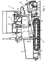
- a paver F in Fig. 1 has a mounted on a chassis 1 chassis 2, here a crawler undercarriage, with at least one, eg hydraulically driven wheel 16.
- a chassis 1 chassis 2 On the chassis 1 is a cab 3, in front of which a primary drive source P, for example an internal combustion engine M, such as a diesel engine, with an integrated generator R and a pump distributor gear 30 are arranged.
- the prime mover P is accessible in the chassis 1, for example via side flaps and an upper hood 4 for maintenance purposes.
- a bunker 5 for paving material. From the bunker 5 leads in the chassis 1, for example, hydraulically driven, a longitudinal conveyor 6 to a arranged behind the chassis transverse distribution device 7, typically a transverse auger.
- a transverse distribution device 7 typically a transverse auger.
- On the chassis 1 Zaholme 8 are articulated on both sides, at the rear of a screed B is mounted, for example, consists of a base board with adjustable in guide systems 9 Ausziehbohlen former 13 and electric heaters H, for example, for pressure bars or tamper 10, 11 and bottom side screed plates.
- the screed B When transporting the paver, the screed B may be supported in the raised transport position shown by means of cylinders 14 relative to the chassis. Furthermore serve cylinder 15 for height adjustment of the articulation points of the two Switzerlandholme 8. Front hydraulic cylinders 17 as hydraulic consumers or functional assemblies are used for example for adjusting the side walls of the bunker. In the cab 3 a control panel 51 is arranged, with which all functional modules and also the primary drive unit P can be controlled and monitored.
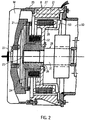
- the internal combustion engine M includes an engine block having a clutch or flywheel housing 20, which may be a standard housing 20 (eg, in accordance with SAE regulations), and which surrounds a power output area of a crankshaft 22 of the internal combustion engine M.
- a flywheel 21 is arranged, with which a torsionally flexible coupling 23 is connected in the housing 20.
- a clutch hub 24 is screwed to the flywheel 21 and drives a second clutch hub 26 via elastic elements 25.
- an input shaft 31 of an output train 29 is used in a rotationally fixed manner, which leads to the pump distributor gear 30.
- the generator R is used, with a stator ring 27 directly flanged to an end flange of the clutch or flywheel housing 20, partially engaging in the interior of the housing 20.
- a mounting flange of the pump distributor gear 30 is mounted on the generator R.
- the generator R is sandwiched, as it were, between the pump distributor gearbox 30 and the internal combustion engine M, partially engaging the housing 20.
- the stator ring 27 is arranged in an unspecified Statorring- intermediate housing 27 '. In an embodiment not shown, the generator R is installed at least to a considerable extent in the housing 20.
- the generator R could also be flanged directly to the engine block of the engine M and replace the flywheel and clutch housing 20, so to speak.
- the generator R is expediently a permanent magnet excited ring generator R and contains inside the stator ring 27 designed as a hollow ring rotor rotor 28 whose diameter can approximately correspond to the diameter of the flywheel 21.
- the rotor 28 is in Fig. 2 screwed directly to a web 32 on the clutch hub 26, runs dry here and can carry a fan 53 for cooling purposes.
- the generator R designed as a ring generator is installed directly between the clutch or flywheel housing 20 and the pump distributor gear 30 on the internal combustion engine M.
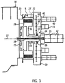
- the crankshaft 22 is connected via the torsionally flexible coupling 23 to the output line 29, which extends through the rotor 28 in the pump distributor gear 30 and through this to a driving pump assembly 42 which is connected to the housing of the pump distributor gearbox 30 is flanged centrally and thus, is driven by the output train 29 permanently.
- second and third gear transmission stages 37, 38, 39 are included.
- the central gear stage 37 is driven by a hollow shaft 33, on which also the web 32 of the rotor 28 of the generator R is arranged rotationally fixed.
- a shiftable clutch 34 can be provided on the output train 29, which decouples the hollow shaft 33 from the output train 29 in the disengaged state, so that then the gear stages 37, 38, 39 in the pump distributor gearbox 30 and also the generator R with the internal combustion engine M running while, for example for transport travel, the driving pump unit 42 is still driven.
- the generator R is permanently driven, and not disconnected.
- hydraulic pumps 40, 41 for hydraulic work functions or functional groups of the paver and / or the screed B are arranged at a plurality of power branches of the pump distributor gear 30, each of which can be driven by the pump distributor gear 30.
- the designed as a ring generator generator R is in the diametrically available installation space around the torsionally flexible coupling 23 sandwiched between the pump distributor gear 30 and the clutch or flywheel housing 20 and possibly partially inserted into this, optionally with a Statorring intermediate housing 27 ', the then even the housing 20 can replace.
- the switchable clutch 34 In the engaged state, the switchable clutch 34, the one rotatably coupled to the output train 29 clutch member 35 and a switching element 36, e.g. a plurality of hydraulically actuated clutch plates, the hollow shaft 33 is driven, so that the rotor 28 of the generator R as well as the gear stages 37, 38, 39 of the pump distributor gear 30 are driven.
- a switching element 36 e.g. a plurality of hydraulically actuated clutch plates
- a hydraulic clutch 34 may be provided in the hydraulic system, a pressure accumulator and / or a permanently driven auxiliary pump to provide the disengaged pressure when disengaged clutch and uncoupled pumps.
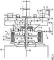
- the embodiment in Fig. 4 has a similar structure as that of Fig. 3 but differs therefrom in that between the output line 29 and the rotor 28 at least one planetary gear stage 43 is provided, preferably in conjunction with the switchable clutch 34, or without a switchable clutch 34.
- the purpose of the planetary gear stage 43 is the runner 28 with a z. B. at nominal speed of the internal combustion engine M optimal speed and thus relative speed with respect to the stator ring 27 to drive, for example, with a bottom or translation.
- the planetary gear stage 43 is housed either partially inside the generator R, or by means of an intermediate housing 44 between the generator R and the pump transfer case 30, or possibly in the pump transfer case.
- a ring toothing 45 is provided on the inside, with which a plurality of planet wheels 46 mesh, which are rotatably mounted on a planet carrier 48.
- the planet carrier 48 drives in this embodiment via a hollow shaft 49 which is mounted in the pump distributor gear 30, the gear stages 37, 38, 39 of the pump distributor gear.
- the output train 29 passes, preferably, directly to the driving pump assembly 42 through the pump distributor gear 30, so that the driving pump unit 42 is permanently driven.
- the planet gears 46 on the planet carrier 48 mesh with an internal toothing 47 of a gear on the hollow shaft 33 which is connected to the web 32 of the ring traveler 28 and, for example, at 33 'is mounted.
- the planet carrier 48 preferably houses the shiftable clutch 34 for selectively coupling or disengaging the planet carrier 48 and the hollow shaft 49 with the output train 29.
- only the hollow shaft 49 can be uncoupled with the coupling 34.
- a liquid cooling system 50 which includes a circuit 60, via the pump transfer case 30, for e.g. Transmission oil, wherein a circulation pump (not shown) may optionally be integrated.
- a separate oil cooler 52 is alternatively or additionally provided in the circuit 60. It could also be another heat carrier used for cooling.
- an auxiliary generator 54 is provided as optional equipment on the pump distributor gear 30 in a bearing 56 (alternatively, the auxiliary generator 54 is mounted separately in a separate bearing 55 in the chassis of the paver F from the pump distributor gear 30).
- the auxiliary generator 54 is driven by a power output 58 of the pump transfer case 30 via a belt drive or propeller shaft 57, e.g. permanent.
- the generator R is u. a. to meet the high power requirements of various electrical heaters H in the paver F, e.g. in the screed B or in the longitudinal conveyor 6 in the chassis 1 to cover with electricity.
- the generator R can, in order to improve the starting behavior of the internal combustion engine M, be disconnected for starting and warming over the shiftable clutch 34.
- the at least one planetary gear stage 43 can drive the generator R at the optimum speed with a corresponding design.
- An electrical or electronic control system with converters or inverters can either be mounted directly on the generator R or placed in a suitable place in the paver.
- the pump distributor gear 30 or its gear stages 37, 38, 39 can also be driven at optimum speeds or speed ratios largely independently of the optimum speed for operating the generator R.
- the generator R is expediently a compact, high-performance permanent magnet-excited ring generator with a hollow ring traveler and is arranged on the internal combustion engine M so that it is at least substantially coaxial to the crankshaft 22 and is penetrated by the output train 29 to the pump distributor gear 30.
Landscapes
- Engineering & Computer Science (AREA)
- Chemical & Material Sciences (AREA)
- Combustion & Propulsion (AREA)
- Transportation (AREA)
- Mechanical Engineering (AREA)
- Architecture (AREA)
- Civil Engineering (AREA)
- Structural Engineering (AREA)
- Connection Of Motors, Electrical Generators, Mechanical Devices, And The Like (AREA)
- Road Paving Machines (AREA)
- Arrangement Of Transmissions (AREA)
Description
Die Erfindung betrifft einen Straßenfertiger der im Oberbegriff des Patentanspruchs 1 angegebenen Art.The invention relates to a paver specified in the preamble of claim 1. Art.
Straßenfertiger weisen üblicherweise zumindest temporär hohe Stromleistung benötigende Heizeinrichtungen z. B. in der Einbaubohle, auf, die vom Generator mit Strom versorgt werden. Es hat sich ein Installationskonzept für den Generator durchgesetzt, bei dem der Generator am Ende eines mit dem Leistungsabgabebereich der Kurbelwelle verbundenen Abtriebsstranges sitzt. Aufgrund des hohen Leistungsbedarfes ist der Generator groß und schwer und wird viel Einbauraum für den Generator benötigt. Seine Antriebs-Verbindung mit der Primärantriebsquelle ist schwierig, da die Primärantriebsquelle neben dem Generator z.B. über ein Pumpenverteilergetriebe zahlreiche andere Sekundärabtriebe oder Funktionsbaugruppen oder deren Hydraulikpumpen antreibt. Wird der Generator an dem oder getrennt vom Pumpenverteilergetriebe platziert und beispielsweise über einen Riementrieb von der Kurbelwelle oder dem Pumpenverteilergetriebe angetrieben, entstehen unerwünschte Querbelastungen an einer Ausgangswelle des Pumpenverteilergetriebes oder an der Kurbelwelle des Verbrennungsmotors (
Bei einem aus
In einem aus
Bei einem aus
In einer Hybrid-Baumaschine gemäß
Bei dem aus
In Straßenfertigern eingesetzte Verbrennungsmotoren sind häufig mit einem relativ ausladenden Schwungrad- oder Kupplungsgehäuse versehen, das z.B. SAE-Vorschriften entsprechend standardisiert sein kann, und ein kostengünstig handelsüblicher integraler oder angebauter Teil des Motorblocks ist. Solche standardisierten Kupplungs- oder Schwungradgehäuse bieten in der Regel im Inneren bisher nicht genutzten Ringraum zwischen der gegebenenfalls vorgesehenen drehelastischen Kupplung am Schwungrad und der Innenwand des Kupplungs- und Schwungradgehäuses.Internal combustion engines used in road pavers are often provided with a relatively bulky flywheel or clutch housing, e.g. SAE regulations, and is a cost-effective commercially available integral or attached part of the engine block. Such standardized clutch or flywheel usually offer in the interior previously unused annulus between the optionally provided torsionally flexible coupling on the flywheel and the inner wall of the clutch and flywheel housing.
Der Erfindung liegt die Aufgabe zugrunde, einen Straßenfertiger der eingangs genannten Art anzugeben, der sich durch einen zur Versorgung der Heizeinrichtungen ausreichend leistungsstarken und platzsparend integrierten Generator auszeichnet.The invention has for its object to provide a paver of the type mentioned above, which is characterized by a sufficiently powerful for powering the heaters and space-saving integrated generator.
Die gestellte Aufgabe wird mit den Merkmalen des Patentanspruchs 1 gelöst.The stated object is achieved with the features of claim 1.
Durch den Einbau des Generators in das Schwungrad- oder Kupplungsgehäuse oder an dessen Stelle, d.h. in üblicherweise nicht oder weitgehend nicht genutzten, vorhandenen Bauraum, wird zur Unterbringung des Generators erheblich Platz eingespart. Das Primärantriebsaggregat wird durch den Generator ggf. nicht oder nicht nennenswert verlängert. Der kompakt untergebrachte Generator deckt auch hohen elektrischen Leistungsbedarf, da er mit hoher und/oder optimaler Relativgeschwindigkeit zwischen dem Läufer und dem Stator betreibbar ist, und verlustarm "direkt an der Quelle" der Motorleistung sitzt. Der Abtriebsstrang, der an den Leistungsausgangsbereich der Kurbelwelle angeschlossen oder anschließbar ist, durchsetzt den Läufer des Generators und nutzt im Inneren des Generators zur Verfügung stehenden oder geschaffenen Raum. Vom Abtriebsstrang abhängige Funktionsgruppen bzw. deren Pumpen, sind unabhängig vom stromaufliegenden Generator über optimale Getriebeabstufungen oder/und Leistungsverzweigungen antreibbar. Der Läufer des Generators ist mit einer von der Drehzahl des Abtriebsstrangs verschiedenen Drehzahl antreibbar. Die Antriebsdrehzahl des Generators ist zu dessen optimaler Leistungsabgabe wählbar, und zwar in einem weiten Bereich unabhängig von beispielsweise der Nenndrehzahl des Verbrennungsmotors (etwa 1700 bis 2300 U/min). Somit lässt sich der Verbrennungsmotor mit hinsichtlich seiner Energiebilanz optimaler Drehzahl betreiben, und werden auch z.B. Pumpen der Funktionsgruppen über das Pumpenverteilergetriebe systemoptimiert angetrieben.By incorporating the generator into or into the flywheel or clutch housing, i. in usually not used or largely unused, existing space, space is saved to accommodate the generator considerably. The prime mover may not be extended or significantly extended by the generator. The compactly accommodated generator also meets high electrical power requirements because it is operable with high and / or optimum relative speed between the rotor and the stator, and sits at a low loss "directly at the source" of the engine power. The power train, which is connected or connectable to the power output range of the crankshaft, passes through the rotor of the generator and uses available or created space inside the generator. Dependent on the output train function groups or their pumps are independent of the upstream generator via optimal transmission gradations and / or power branches drivable. The rotor of the generator can be driven at a different speed from the output of the output train. The drive speed of the generator is selectable for its optimum power output, in a wide range independent of, for example, the rated speed of the engine (about 1700 to 2300 U / min). Thus, the internal combustion engine can be operated at the optimum speed with respect to its energy balance, and are also used e.g. Pumps of the functional groups are system-optimized driven via the pump distributor gearbox.
Es sind zwar Hybridantriebe für Baumaschinen bekannt, in denen zur Umweltentlastung und vor allem zur Brennstoffeinsparung ein Verbrennungsmotor mit einem Generator/ Elektromotor kombiniert ist, der über eine Batterie den Verbrennungsmotor mit zusätzlicher Abtriebsleistung unterstützt oder zeitweise die Batterie lädt. Hierbei dient der Generator/ Elektromotor jedoch nicht zur unmittelbaren Versorgung weiterer, gegebenenfalls hohe Stromleistung benötigender Ausstattungsteile eines Fahrzeugs, sondern ist hierfür meist noch eine übliche vom Verbrennungsmotor separat angetriebene Lichtmaschine vorgesehen (DEMTECH AG, CH- 6331 Hünenberg CH, www.demtech-ch/de-hybriddrive.htm).Although there are known hybrid drives for construction machinery in which for environmental relief and especially for fuel saving, an internal combustion engine is combined with a generator / electric motor that supports the engine with additional output power via a battery or temporarily charges the battery. In this case, however, the generator / electric motor does not serve for the immediate supply of additional, possibly high, power-consuming equipment of a vehicle, but for this purpose usually a conventional alternator separately driven by the internal combustion engine is provided (DEMTECH AG, CH-6331 Hünenberg CH, www.demtech-ch / de-hybriddrive.htm ).
Dabei nutzt der Generator bisher nicht genutzten Einbauraum im, vorzugsweise standardisierten und somit kostengünstigen, Schwungrad- oder Kupplungsgehäuse zumindest zum Teil, und zwar in dem großen Gehäuse einen Ringraum um die relativ kleinbauende drehelastische Kupplung. Dadurch wird im Straßenfertiger Einbauraum zum Unterbringen des Generators eingespart oder für andere Funktionsgruppen nutzbar.In this case, the generator uses previously unused installation space in, preferably standardized and thus cost, flywheel or clutch housing at least in part, in the large housing an annular space around the relatively small-sized torsionally flexible coupling. As a result, in the paver installation space for accommodating the generator can be saved or used for other functional groups.
Alternativ kann ein Statorring oder ein den Statorring enthaltendes Zwischengehäuse des Generators zwischen dem Verbrennungsmotor und dem Pumpenverteilergetriebe am Motorblock direkt montiert sein. Der Generator ersetzt das Kupplungs- und Schwungradgehäuse, und dient als Träger des Pumpenverteilergetriebes.Alternatively, a stator ring or an intermediate housing of the generator containing the stator ring may be directly mounted between the internal combustion engine and the pump distributor gearbox on the engine block. The generator replaces the clutch and flywheel housing, and serves as a carrier of the pump distributor gearbox.
Besonders zweckmäßig ist der Generator ein permanentmagneterregter Ringgenerator mit einem hohlen Ringläufer zum Durchführen des Abtriebsstrangs zum Pumpenverteilergetriebe. Der Ringgenerator ist kompakt, insbesondere axial relativ kurz, und sehr leistungsstark, da die Relativgeschwindigkeit zwischen dem Ringläufer und einem Statorring bauartbedingt hoch ist. In dem Zwischenraum zwischen dem Verbrennungsmotor und dem Pumpenverteilergetriebe ist auch in Durchmesserrichtung relativ viel Platz verfügbar, der zum Unterbringen von Wicklungen und/oder Steuereinrichtungen des Ringgenerators nutzbar ist.Particularly suitably, the generator is a permanent magnet excited ring generator with a hollow ring traveler for performing the output train to the pump distributor gearbox. The ring generator is compact, in particular axially relatively short, and very powerful, since the relative speed between the rotor and a stator ring is high due to the design. In the space between the internal combustion engine and the pump distributor gear relatively much space is also available in the diameter direction, which is available for accommodating windings and / or control means of the ring generator.
Bei einer bevorzugten Ausführungsform führt der Abtriebsstrang zu dem am Verbrennungsmotor anschließend an den Generator montierten, leistungsverzweigenden Pumpenverteilergetriebe, von dem weitere Funktionsgruppen nachrangig zum Generator oder allenfalls parallel zu diesem angetrieben werden. Trotz des integrierten Generators ergibt sich mit dem direkt oder indirekt angebauten Pumpenverteilergetriebe ein kompaktes Primärantriebsaggregat.In a preferred embodiment, the power take-off leads to the power-splitting pump distributor transmission, which is subsequently mounted on the combustion engine to the generator and from which further functional groups are driven subordinate to the generator or at most parallel to it. Despite the integrated generator, a compact primary drive unit results with the directly or indirectly mounted pump distributor gearbox.
Wenn der Läufer bei laufendem Verbrennungsmotor permanent angetrieben wird, definiert er ein Massenträgheitsmoment, das es ermöglicht, nur ein kleines oder kein Schwungrad vorzusehen.When the rotor is permanently driven while the internal combustion engine is running, it defines an inertia moment that makes it possible to provide only a small or no flywheel.
Bei einer weiteren Ausführungsform ist dem Generator zumindest eine Planetengetriebe-Stufe zugeordnet, um den Generator und den Verbrennungsmotor jeweils mit optimalen Drehzahlen betreiben zu können. Die Planetengetriebestufe baut klein, lässt sich in teilweise ohnedies verfügbarem Bauraum unterbringen, und erzeugt keine unerwünschten Querkräfte.In a further embodiment, the generator is associated with at least one planetary gear stage in order to operate the generator and the internal combustion engine at optimal speeds. The planetary gear stage builds small, can be accommodated in partially without this available space, and generates no undesirable lateral forces.
Bei einer weiteren Ausführungsform ist zwischen der Kurbelwelle oder dem Abtriebsstrang und dem Läufer des Generators, und/oder dem Pumpenverteilergetriebe eine schaltbare Kupplung angeordnet. Die schaltbare Kupplung ermöglicht es, den Generator und/oder das Pumpenverteilergetriebe vom Verbrennungsmotor abzukoppeln, was beispielsweise die Schlepplast des Verbrennungsmotors beim Start, insbesondere unter extremen Witterungsbedingungen und/oder bei Transportfahrt verringern lässt, und das Startverhalten verbessert. Hierbei kann auch die gegebenenfalls vorgesehene Planetengetriebe-Stufe abgekoppelt werden. Zweckmäßig wird die schaltbare Kupplung, vorzugsweise zum Abkuppeln der Planetengetriebe-Stufe und des Pumpenverteilergetriebes vom Abtriebsstrang, in der Planetengetriebe-Stufe oder im Pumpenverteilergetriebe untergebracht, um zur kompakten Bauweise beizutragen, und dort gegebene Möglichkeiten zur Lagerung, Kühlung, hydraulischen Versorgung und dgl. mitzunutzen.In a further embodiment, a switchable coupling is arranged between the crankshaft or the output train and the rotor of the generator, and / or the pump distributor gear. The switchable coupling allows the generator and / or To decouple the pump transfer case from the engine, which for example, the towing load of the engine at start, especially under extreme weather conditions and / or reduce transport travel, and improves the starting behavior. In this case, the optionally provided planetary gear stage can be decoupled. Conveniently, the shiftable clutch, preferably for uncoupling the planetary gear stage and the pump distributor gear from the output train, housed in the planetary gear stage or pump transfer case to contribute to the compact design, and there given opportunities for storage, cooling, hydraulic supply and the like ,
Planetengetriebe- Stufe und des Pumpenverteilergetriebes vom Abtriebsstrang, in der Planetengetriebe- Stufe oder im Pumpenverteilergetriebe untergebracht, um zur kompakten Bauweise beizutragen, und dort gegebene Möglichkeiten zur Lagerung, Kühlung, hydraulischen Versorgung und dgl. mitzunutzen.Planetary gear stage and the pump distributor gear from the power train, housed in the planetary gear stage or pump transfer case to contribute to the compact design, and there given opportunities for storage, cooling, hydraulic supply and the like.
Bei einer weiteren, zweckmäßigen Ausführungsform ist die schaltbare Kupplung wirkungsmäßig zwischen dem zu einem beispielsweise vom Pumpenverteilergetriebe getragenen Fahrantriebs-Pumpenaggregat durchgehenden Abtriebsstrang und einer Eingangswelle des Pumpenverteilergetriebes sowie der Planetengetriebe-Stufe angeordnet, um ausgerückt bei nach wie vor angetriebenem Fahrantriebs-Pumpenaggregat die Planetengetriebe-Stufe und/oder die Eingangswelle des Pumpenverteilergetriebes abzukuppeln. Dies kann ein Betriebszustand für Transportfahrt des Straßenfertigers mit voller Leistung des Verbrennungsmotors für hohe Transportgeschwindigkeit sein. Bei Transportfahrt werden die vom Pumpenverteilergetriebe versorgten Funktionsgruppen und unter Umständen der Generator zum Betreiben von Heizungseinrichtungen nicht benötigt. In diesem Betriebszustand wird auch der Treibstoffverbrauch deutlich reduziert.In another expedient embodiment, the shiftable clutch is operatively disposed between the output train passing through to a traction drive pump assembly passing through, for example, the pump transfer case and an input shaft of the pump transfer case and planetary gear stage to disengage the epicyclic gear stage when the traction drive pump assembly is still driven and / or disengage the input shaft of the pump transfer case. This may be an operating condition for road traction conveyor travel at full power of the high transport speed internal combustion engine. During transport, the functional groups supplied by the pump distributor gearbox and, under certain circumstances, the generator for operating heating devices are not required. In this operating state, the fuel consumption is significantly reduced.
Da aufgrund hoher, vom Generator abgenommener Stromleistung und relativ hoher Drehzahlen zusätzlich Wärme generiert werden kann, ist bei einer zweckmäßigen Ausführungsform ein Kühlsystem zumindest für den Generator, vorzugsweise auch die PlanetengetriebeStufe, vorgesehen. Das Kühlsystem nimmt in diesem Bereich generierte und auf normale Weise schlecht abzuführende Wärme auf und ermöglicht einen optimalen Betrieb des Ringgenerators.Since, due to high, removed by the generator power and relatively high speeds additional heat can be generated in a useful embodiment, a cooling system at least for the generator, preferably also the PlanetengetriebeStufe provided. The cooling system absorbs heat generated in this area and is poorly dissipated in the normal way and enables optimum operation of the ring generator.
In einer baulich einfachen Ausführungsform ist am Läufer wenigstens ein Kühllüfterrad angeordnet, wobei der Ringläufer trocken läuft und in diesem Bereich mit Luftkühlung gekühlt wird.In a structurally simple embodiment, at least one cooling fan wheel is arranged on the rotor, the rotor running dry and being cooled in this area with air cooling.
Alternativ kann ein Flüssigkeitskühlsystem vorgesehen sein, das, vorzugsweise, zumindest einen dann über das Pumpenverteilergetriebe geführten Kühlkreislauf, z.B. mit dem Getriebeöl oder einem anderen Wärmeträger, umfasst. Das Pumpenverteilergetriebe enthält nennenswertes Ölvolumen und leitet im Öl enthaltene Wärme effizient nach außen ab. Deshalb lässt sich das Pumpenverteilergetriebe ohne aufwändige externe Kühleinrichtungen zum Kühlen des Ringgenerators und dessen Planetenradgetriebe-Stufe nutzen, obwohl ggf. sogar ein zusätzlicher externer Ölkühler vorgesehen sein könnte.Alternatively, a liquid cooling system may be provided which, preferably, at least one cooling circuit then passed through the pump transfer case, e.g. with the gear oil or another heat transfer medium. The pump transfer case contains significant oil volume and efficiently dissipates heat contained in the oil to the outside. Therefore, the pump transfer case can be used without consuming external cooling devices for cooling the ring generator and its planetary gear stage, although possibly even an additional external oil cooler could be provided.
Bei einer weiteren, zweckmäßigen Ausführungsform ist die schaltbare Kupplung wirkungsmäßig zwischen dem zu einem beispielsweise vom Pumpenverteilergetriebe getragenen Fahrantriebs-Pumpenaggregat durchgehenden Abtriebsstrang und einer Eingangswelle des Pumpenverteilergetriebes sowie der Planetengetriebe-Stufe angeordnet, um ausgerückt bei nach wie vor angetriebenem Fahrantriebs-Pumpenaggregat die Planetengetriebe-Stufe und/oder die Eingangswelle des Pumpenverteilergetriebes abzukuppeln. Dies kann ein Betriebszustand für Transportfahrt des Straßenfertigers mit voller Leistung des Verbrennungsmotors für hohe Transportgeschwindigkeit sein. Bei Transportfahrt werden die vom Pumpenverteilergetriebe versorgten Funktionsgruppen und unter Umständen der Generator zum Betreiben von Heizungseinrichtungen nicht benötigt. In diesem Betriebszustand wird auch der Treibstoffverbrauch deutlich reduziert.In another expedient embodiment, the shiftable clutch is operatively disposed between the output train passing through to a traction drive pump assembly passing through, for example, the pump transfer case and an input shaft of the pump transfer case and planetary gear stage to disengage the epicyclic gear stage when the traction drive pump assembly is still driven and / or disengage the input shaft of the pump transfer case. This may be an operating condition for road traction conveyor travel at full power of the high transport speed internal combustion engine. During transport, the functional groups supplied by the pump distributor gearbox and, under certain circumstances, the generator for operating heating devices are not required. In this operating state, the fuel consumption is significantly reduced.
Da aufgrund hoher, vom Generator abgenommener Stromleistung und relativ hoher Drehzahlen zusätzlich Wärme generiert werden kann, ist bei einer zweckmäßigen Ausführungsform ein Kühlsystem zumindest für den Generator, vorzugsweise auch die PlanetengetriebeStufe, vorgesehen. Das Kühlsystem nimmt in diesem Bereich generierte und auf normale Weise schlecht abzuführende Wärme auf und ermöglicht einen optimalen Betrieb des Ringgenerators.Since, due to high, removed by the generator power and relatively high speeds additional heat can be generated in a useful embodiment, a cooling system at least for the generator, preferably also the PlanetengetriebeStufe provided. The cooling system absorbs heat generated in this area and is poorly dissipated in the normal way and enables optimum operation of the ring generator.
In einer baulich einfachen Ausführungsform ist am Läufer wenigstens ein Kühllüfterrad angeordnet, wobei der Läufer trocken läuft und in diesem Bereich mit Luftkühlung gekühlt wird.In a structurally simple embodiment, at least one cooling fan wheel is arranged on the rotor, wherein the rotor runs dry and is cooled in this area with air cooling.
Alternativ kann ein Flüssigkeitskühlsystem vorgesehen sein, das, vorzugsweise, zumindest einen dann über das Pumpenverteilergetriebe geführten Kühlkreislauf, z.B. mit dem Getriebeöl oder einem anderen Wärmeträger, umfasst. Das Pumpenverteilergetriebe enthält nennenswertes Ölvolumen und leitet im Öl enthaltene Wärme effizient nach außen ab. Deshalb lässt sich das Pumpenverteilergetriebe ohne aufwändige externe Kühleinrichtungen zum Kühlen des Ringgenerators und dessen Planetenradgetriebe-Stufe nutzen, obwohl ggf. sogar ein zusätzlicher externer Ölkühler vorgesehen sein könnte.Alternatively, a liquid cooling system may be provided which, preferably, at least one cooling circuit then passed through the pump transfer case, e.g. with the gear oil or another heat transfer medium. The pump transfer case contains significant oil volume and efficiently dissipates heat contained in the oil to the outside. Therefore, the pump transfer case can be used without consuming external cooling devices for cooling the ring generator and its planetary gear stage, although possibly even an additional external oil cooler could be provided.
Der Innendurchmesser des hohlen Läufers des Ringgenerators kann in etwa dem Außendurchmesser des Schwungrades des Verbrennungsmotors entsprechen. Es ergibt sich aufgrund des relativ großen Durchmessers des Ringgenerators hohe Relativgeschwindigkeit zwischen dem Ringläufer und dem Statorring und damit eine optimale Leistungsausbeute bzw. eine hohe Stromleistung.The inner diameter of the hollow rotor of the ring generator may correspond approximately to the outer diameter of the flywheel of the internal combustion engine. Due to the relatively large diameter of the ring generator, the result is a high relative speed between the ring traveler and the stator ring and thus an optimum power yield or a high power output.
Zweckmäßig wird vom Pumpenverteilergetriebe über einen Riementrieb oder eine Gelenkwelle wenigstens ein weiterer Generator angetrieben, sozusagen ein Hilfsgenerator für nebengeordnete Funktionsgruppen, oder falls der Haupt-Generator abkuppelbar ist. Der HilfsGenerator kann z.B. am Pumpenverteilergetriebe gelagert sein, so dass er die Kurbelwelle des Verbrennungsmotors nicht unerwünscht mit Querkräften beaufschlagt, oder kann sogar im Chassis des Straßenfertigers gelagert sein. Für den Hilfsgenerator lässt sich ein optimaler Platz im Straßenfertiger wählen, weil er dank des Riementriebes oder einer Gelenkwelle gegenüber dem Primärantriebsaggregat versetzt platzierbar ist.It is useful from the pump distributor gearbox driven by a belt drive or a propeller shaft at least one other generator, so to speak, an auxiliary generator for sibling function groups, or if the main generator can be uncoupled. The auxiliary generator may, for example, be mounted on the pump distributor gear, so that it does not undesirably apply lateral forces to the crankshaft of the internal combustion engine, or may even be mounted in the chassis of the road paver. For the auxiliary generator can choose an optimal place in the paver, because it is offset offset thanks to the belt drive or a propeller shaft relative to the prime mover.
Anhand der Zeichnungen werden Ausführungsformen des Erfindungsgegenstandes erläutert. Es zeigen:
- Fig. 1
- eine schematische Seitenansicht eines Straßenfertigers,
- Fig. 2
- einen Teil eines Achsschnittes zur Verdeutlichung der Integration eines Generators direkt beim Leistungsabgabebereich der Kurbelwelle des Verbrennungsmotors,
- Fig. 3
- eine Schemadarstellung einer weiteren Ausführungsform, und
- Fig. 4
- eine Schemadarstellung einer weiteren Ausführungsform.
- Fig. 1
- a schematic side view of a paver,
- Fig. 2
- a part of an axial section to illustrate the integration of a generator directly at the power output range of the crankshaft of the internal combustion engine,
- Fig. 3
- a schematic representation of another embodiment, and
- Fig. 4
- a schematic representation of another embodiment.
Ein Straßenfertiger F in
In Arbeitsfahrtrichtung des Straßenfertigers F in
Gemäß
Bei einer nicht gezeigten Alternative könnte der Generator R auch direkt an den Motorblock des Verbrennungsmotors M angeflanscht sein und sozusagen das Schwungrad- und Kupplungsgehäuse 20 ersetzen.In an alternative, not shown, the generator R could also be flanged directly to the engine block of the engine M and replace the flywheel and
Der Generator R ist zweckmäßig ein permanentmagneterregter Ringgenerator R und enthält innen im Statorring 27 einen als hohler Ringläufer ausgebildeter Läufer 28, dessen Durchmesser annähernd dem Durchmesser des Schwungrades 21 entsprechen kann.The generator R is expediently a permanent magnet excited ring generator R and contains inside the
Der Läufer 28 ist in
In der Ausführungsform in
Im Pumpenverteilergetriebe 30 sind erste, zweite und dritte Zahnradgetriebe-Stufen 37, 38, 39 enthalten. Die zentrale Getriebestufe 37 wird durch eine Hohlwelle 33 angetrieben, auf der auch der Steg 32 des Läufers 28 des Generators R drehfest angeordnet ist.In the
Im Pumpenverteilergetriebe 30 kann auf dem Abtriebsstrang 29 eine schaltbare Kupplung 34 vorgesehen sein, die in ausgerücktem Zustand die Hohlwelle 33 vom Abtriebsstrang 29 abkuppelt, so dass dann die Getriebestufen 37, 38, 39 im Pumpenverteilergetriebe 30 und auch der Generator R bei laufendem Verbrennungsmotor M stehen, während, z.B. für Transportfahrt, das Fahrpumpenaggregat 42 nach wie vor angetrieben wird. Gegebenenfalls wird auch der Generator R permanent angetrieben, und nicht abgekuppelt.In the
An mehreren Leistungsverzweigungen des Pumpenverteilergetriebes 30 sind beispielsweise Hydraulikpumpen 40, 41 für hydraulische Arbeitsfunktionen oder Funktionsgruppen des Straßenfertigers und/oder der Einbaubohle B angeordnet, die jeweils vom Pumpenverteilergetriebe 30 antreibbar sind. Der als Ringgenerator ausgebildete Generator R ist in dem in Durchmesserrichtung zur Verfügung stehenden Einbauraum um die drehelastische Kupplung 23 sandwichartig zwischen dem Pumpenverteilergetriebe 30 und dem Kupplungs- oder Schwungradgehäuse 20 und ggf. teilweise in dieses eingesetzt, gegebenenfalls mit einem Statorring-Zwischengehäuse 27', das dann sogar das Gehäuse 20 ersetzen kann.For example,
In eingerücktem Zustand der schaltbaren Kupplung 34, die einen mit dem Abtriebsstrang 29 drehfest gekuppelten Kupplungsteil 35 und ein Schaltelement 36, z.B. mehrere hydraulisch betätigbare Kupplungsscheiben, aufweist, wird die Hohlwelle 33 angetrieben, so dass der Läufer 28 des Generators R wie auch die Getriebestufen 37, 38, 39 des Pumpenverteilergetriebes 30 angetrieben werden.In the engaged state, the switchable clutch 34, the one rotatably coupled to the
Es wäre denkbar, in
Im Falle einer hydraulischen Kupplung 34 kann im Hydrauliksystem ein Druckspeicher und/oder eine permanent antreibbare Hilfspumpe vorgesehen sein, um bei ausgerückter Kupplung und abgekuppelten Pumpen den Schaltdruck zum Einrücken bereitzustellen.In the case of a hydraulic clutch 34 may be provided in the hydraulic system, a pressure accumulator and / or a permanently driven auxiliary pump to provide the disengaged pressure when disengaged clutch and uncoupled pumps.
Die Ausführungsform in
Die Planetenrad-Getriebestufe 43 ist entweder zum Teil im Inneren des Generators R untergebracht, oder mittels eines Zwischengehäuses 44 zwischen dem Generator R und dem Pumpenverteilergetriebe 30, oder ggf. im Pumpenverteilergetriebe. In dem Zwischengehäuse 44 ist innen eine Ringverzahnung 45 vorgesehen, mit der mehrere Planetenräder 46 kämmen, die auf einem Planetenradträger 48 drehbar gelagert sind. Der Planetenradträger 48 treibt in dieser Ausführungsform über eine Hohlwelle 49, die im Pumpenverteilergetriebe 30 gelagert ist, die Getriebestufen 37, 38, 39 des Pumpenverteilergetriebes. Der Abtriebsstrang 29 geht, vorzugsweise, direkt zu dem Fahrpumpenaggregat 42 durch das Pumpenverteilergetriebe 30 durch, so dass das Fahrpumpenaggregat 42 permanent angetrieben wird. Die Planetenräder 46 auf dem Planetenradträger 48 kämmen mit einer Innenverzahnung 47 eines Zahnrades auf der Hohlwelle 33, die mit dem Steg 32 des Ringläufers 28 verbunden und beispielsweise bei 33' gelagert ist. Im Planetenradträger 48 ist, vorzugsweise, die schaltbare Kupplung 34 untergebracht, um wahlweise den Planetenradträger 48 und die Hohlwelle 49 mit dem Abtriebsstrang 29 zu kuppeln oder davon abzukuppeln. Gegebenenfalls lässt sich mit der Kupplung 34 nur die Hohlwelle 49 abkuppeln.The
Um im Generator R und gegebenenfalls der Planetenrad-Getriebestufe 43 generierte Wärme wirkungsvoll abzuführen, ist ein Flüssigkeits-Kühlsystem 50 vorgesehen, das einen über das Pumpenverteilergetriebe 30 geführten Kreislauf 60 für, z.B. Getriebeöl, aufweist, wobei eine Zirkulationspumpe (nicht gezeigt) optional integriert sein kann. Gegebenenfalls ist alternativ oder additiv in den Kreislauf 60 ein gesonderter Ölkühler 52 vorgesehen. Es könnte auch ein anderer Wärmeträger zum Kühlen verwendet werden.In order to effectively dissipate heat generated in the generator R and, if appropriate, the
Ferner ist als optionale Ausstattung am Pumpenverteilergetriebe 30 in einer Lagerung 56 ein Hilfsgenerator 54 vorgesehen (alternativ ist der Hilfsgenerator 54 in einer eigenen Lagerung 55 im Chassis des Straßenfertigers F vom Pumpenverteilergetriebe 30 getrennt gelagert). Der Hilfsgenerator 54 wird beispielsweise von einem Leistungsausgang 58 des Pumpenverteilergetriebes 30 über einen Riementrieb oder eine Gelenkwelle 57 angetrieben, z.B. permanent.Furthermore, an
Der Generator R dient u. a. dazu, den hohen Leistungsbedarf verschiedener elektrischer Heizeinrichtungen H im Straßenfertiger F, z.B. in der Einbaubohle B oder auch im Bereich der Längsfördervorrichtung 6 im Chassis 1 mit Strom zu decken.The generator R is u. a. to meet the high power requirements of various electrical heaters H in the paver F, e.g. in the screed B or in the longitudinal conveyor 6 in the chassis 1 to cover with electricity.
Der Generator R kann, um das Startverhalten des Verbrennungsmotors M zu verbessern, zum Starten und Warmlaufen über die schaltbare Kupplung 34 abgetrennt werden. Es ist allerdings auch möglich, nur das Pumpenverteilergetriebe 30 abzukoppeln und den Generator R anzutreiben, um nach dem Start bereits die Heizeinrichtungen H auf Betriebstemperatur zu bringen, ohne die Schleppwiderstände des Pumpenverteilergetriebes und der daran angeschlossenen Funktionsgruppen überwinden zu müssen. Ferner ist es denkbar, den Generator R und/oder das Pumpenverteilergetriebe 30 über die schaltbare Kupplung 34 bei Transportfahrt abzukoppeln, da bei Transportfahrt im Regelfall keine Heizeinrichtungen betätigt oder Funktionsbaugruppen gesteuert werden. Nur das Fahrpumpenaggregat 42 wird dann angetrieben, um mit optimal hoher Transportgeschwindigkeit und/oder optimiertem Brennstoffverbrauch fahren zu können.The generator R can, in order to improve the starting behavior of the internal combustion engine M, be disconnected for starting and warming over the
Die zumindest eine Planetenrad-Getriebestufe 43 kann bei entsprechender Auslegung den Generator R mit optimaler Drehzahl antreiben. Um den Generator R platzsparend unterzubringen, ist es gegenüber bewährten Baukonzepten gegebenenfalls nur erforderlich, die Pumpenverteilergetriebewelle bzw. den Abtriebsstrang 29 entsprechend der axialen Länge des Generators zu verlängern. Eine elektrische oder elektronische Steuerung mit Umrichtern oder Wechselrichtern kann entweder am Generator R direkt angebaut sein, oder an geeigneter Stelle im Straßenfertiger platziert werden. Das Pumpenverteilergetriebe 30 bzw. dessen Getriebestufen 37, 38, 39 können ebenfalls mit optimalen Drehzahlen oder Drehzahlverhältnissen weitgehend unabhängig von der zum Betrieb des Generators R optimalen Drehzahl angetrieben werden. Der Generator R ist zweckmäßig ein kompakter, leistungsstarker permanentmagneterregter Ringgenerator mit hohlem Ringläufer und ist so am Verbrennungsmotor M angeordnet, dass er zumindest im Wesentlichen zur Kurbelwelle 22 koaxial ist und von dem Abtriebsstrang 29 zum Pumpenverteilergetriebe 30 durchsetzt wird.The at least one
Claims (12)
- Road paver (F), comprising as a primary driving aggregate (P) a combustion engine (M), particularly a diesel engine, the crank-shaft (22) of the combustion engine (M) ending in a power output region, and at least one generator (R) as well as at least one distribution gear mechanism for pumps (30), the generator (R) being drivable by the combustion engine (M) via the power output region at least for supplying electric heating devices arranged at the road paver (F) and/or in a paving screed (B) of the road paver (F), characterised in that the generator (R) is connected to the combustion engine (M) coaxial to the crankshaft (22) at or in a casing (20) for a clutch or for a flywheel or instead of the casing (20) for a clutch or for a flywheel, that the distribution gear mechanism for pumps (30) is installed at the side of the generator (R) that faces away from the combustion engine (M), that a drive train (29) permanently connected by a torsionally flexible coupling (23) in the power output region to the crankshaft (22) extends through a runner of the generator (R) at least to the distribution gear mechanism for pumps (30), and that at least the generator (R) can be driven with a speed different from the speed of the drive train (29).
- Road paver according to claim 1, characterised in that the generator (R) is mounted at least in part in a ring space of a casing (20) for a clutch or for a flywheel that is provided at a engine block of the combustion engine (M), and that the ring space is provided between the torsionally flexible coupling (23)and the casing (20).
- Road paver according to claim 1, characterised in that the generator (R) is arranged with a stator ring (27) or with an intermediate casing containing the stator ring between the engine block of the combustion engine (M) and the distribution gear mechanism for pumps (30).
- Road paver according to claim 1, characterised in that the generator (R) is a ring generator with permanent magnet excitation and a hollow ring runner for accommodating the drive train (29).
- Road paver according to claim 2 or 3, characterised in that the distribution gear mechanism for pumps (30), preferably a power branching gear mechanism, is mounted either at the generator (R) or at the, preferably standardised, casing (20) for a clutch or for a flywheel which casing (20) contains the generator (R).
- Road paver according to claim 1, characterised in that the drive train (29) extends through the distribution gear mechanism for pumps (30), and that the generator (R) and the distribution gear mechanism for pumps (30) both can be driven with a speed different from the speed of the drive train (29).
- Road paver according to at least one of the preceding claims, characterised in that at least one planetary gear stage (43) is arranged between the runner of the generator (R) and the drive train (29), preferably at least partly within the runner (28) and/or within an intermediate casing (44) arranged between the generator (R) and the distribution gear mechanism for pumps (30).
- Road paver according to at least one of the preceding claims, characterised in that a switchable clutch (34) is arranged between the power output region and the runner (28) or the drive train (29).
- Road paver according to claim 8, characterised in that the switchable clutch (34) functionally is arranged between the drive train (29) permanently driving a travelling drive pump aggregate (42) flanged to the distribution gear mechanism (30) for pumps and the planetary wheel gear stage (43) and/or of an input shaft (33, 49) of the distribution gear mechanism for pumps (30).
- Road paver according to at least one of the preceding claims, characterised in that a cooling system (50) is provided for the generator (R), preferably also for the planetary gear stage (43).
- Road paver according to claim 10, characterised in that the runner (28) of the generator (R) is running dry and is connected with at least one cooling fan wheel (53).
- Road paver according to claim 10, characterised in that the cooling system (50) is a liquid cooling system, and preferably includes a cooling circuit (60) at least extending through the distribution gear mechanism for pumps (30).
Priority Applications (4)
| Application Number | Priority Date | Filing Date | Title |
|---|---|---|---|
| EP09006977.4A EP2256247B2 (en) | 2009-05-25 | 2009-05-25 | Finisher |
| PL09006977T PL2256247T5 (en) | 2009-05-25 | 2009-05-25 | Road finisher |
| US12/722,488 US8628271B2 (en) | 2009-05-25 | 2010-03-11 | Road paver |
| CN2010101714814A CN101899810B (en) | 2009-05-25 | 2010-05-13 | Road finisher |
Applications Claiming Priority (1)
| Application Number | Priority Date | Filing Date | Title |
|---|---|---|---|
| EP09006977.4A EP2256247B2 (en) | 2009-05-25 | 2009-05-25 | Finisher |
Publications (3)
| Publication Number | Publication Date |
|---|---|
| EP2256247A1 EP2256247A1 (en) | 2010-12-01 |
| EP2256247B1 EP2256247B1 (en) | 2013-10-23 |
| EP2256247B2 true EP2256247B2 (en) | 2017-08-09 |
Family
ID=41059766
Family Applications (1)
| Application Number | Title | Priority Date | Filing Date |
|---|---|---|---|
| EP09006977.4A Active EP2256247B2 (en) | 2009-05-25 | 2009-05-25 | Finisher |
Country Status (4)
| Country | Link |
|---|---|
| US (1) | US8628271B2 (en) |
| EP (1) | EP2256247B2 (en) |
| CN (1) | CN101899810B (en) |
| PL (1) | PL2256247T5 (en) |
Families Citing this family (16)
| Publication number | Priority date | Publication date | Assignee | Title |
|---|---|---|---|---|
| CN102367757A (en) * | 2011-04-01 | 2012-03-07 | 湖南华强电气有限公司 | Automobile engine |
| DE102011111822A1 (en) * | 2011-08-27 | 2013-02-28 | Rheinmetall Landsysteme Gmbh | tracked vehicle |
| PL2565334T3 (en) | 2011-08-31 | 2017-07-31 | Joseph Vögele AG | Construction machine with oil-cooled generator |
| BR112015018038A2 (en) * | 2013-02-14 | 2017-07-11 | Ammann Schweiz Ag | METHOD FOR HEATING A PAVER SABLE OF AN ASPHALT PAVER |
| CH707888A1 (en) * | 2013-04-12 | 2014-10-15 | Liebherr Machines Bulle Sa | Drive system. |
| US9382675B2 (en) * | 2014-06-16 | 2016-07-05 | Caterpillar Paving Products Inc. | Electric powered systems for paving machines |
| CN107849909A (en) * | 2015-06-12 | 2018-03-27 | 西部钻探产品有限公司 | For in the rotatable portion of system and/or it is middle provide pressure fluid system |
| KR101846874B1 (en) * | 2016-10-24 | 2018-04-09 | 현대자동차 주식회사 | Power train |
| KR101846875B1 (en) * | 2016-10-24 | 2018-04-09 | 현대자동차 주식회사 | Power train |
| CN108071058B (en) * | 2016-11-18 | 2024-04-30 | 徐工集团工程机械股份有限公司 | Paver hydraulic control system and paver |
| US10246834B1 (en) * | 2017-11-20 | 2019-04-02 | Caterpillar Paving Products Inc. | Tamper bar and wear plate for screed assembly of paving machine |
| US11214930B2 (en) | 2018-02-19 | 2022-01-04 | McAnany Construction, Inc. | System and method for modifying and repaving paved surfaces |
| US11162232B2 (en) | 2018-10-08 | 2021-11-02 | Ligchine International Corporation | Drive system for screeding concrete |
| US11560727B2 (en) | 2018-10-08 | 2023-01-24 | Ligchine International Corporation | Apparatus for screeding concrete |
| WO2022182755A1 (en) | 2021-02-23 | 2022-09-01 | Ligchine International Corporation | Swing boom concrete screeding apparatus |
| DE102022103465A1 (en) | 2021-12-10 | 2023-06-15 | Liebherr-Components Biberach Gmbh | Construction and/or material handling machine |
Citations (3)
| Publication number | Priority date | Publication date | Assignee | Title |
|---|---|---|---|---|
| DE19545922A1 (en) † | 1995-12-08 | 1997-09-18 | Magnet Motor Gmbh | Motor vehicle |
| DE19931963A1 (en) † | 1999-07-12 | 2001-01-18 | Audi Ag | Drive device |
| US6668953B1 (en) † | 1999-08-02 | 2003-12-30 | Luk Lamellan Und Kunpplungsbau Beteiligungs Kg | Power train having an internal combustion engine, energy converter, clutch, and accessory |
Family Cites Families (23)
| Publication number | Priority date | Publication date | Assignee | Title |
|---|---|---|---|---|
| US2382096A (en) * | 1944-02-14 | 1945-08-14 | Viber Company | Paving machine |
| US2660892A (en) * | 1952-03-01 | 1953-12-01 | Deere Mfg Co | Power train for vehicle power takeoff shaft and auxiliary unit |
| US2911892A (en) * | 1956-02-08 | 1959-11-10 | Iowa Mfg Co Cedar Rapids | Surfacing machine control means |
| US3055280A (en) * | 1959-02-20 | 1962-09-25 | Pavement Salvage Inc | Means for treating bituminous pavement |
| US3453939A (en) * | 1966-06-21 | 1969-07-08 | Iowa Mfg Co | Bituminous paver |
| US3665821A (en) * | 1970-08-17 | 1972-05-30 | Medusa Portland Cement Co | Continuous curb-forming machine |
| DE3536247A1 (en) | 1985-10-10 | 1987-04-16 | Jenbacher Werke Vertriebsgesel | Vehicle, especially commercial vehicle with hybrid drive |
| EP0489969B2 (en) | 1990-12-14 | 1999-11-17 | Joseph Vögele AG | Finisher |
| DE9308801U1 (en) * | 1993-06-14 | 1993-08-19 | Voegele Ag J | Paver |
| DE19917665A1 (en) * | 1999-04-19 | 2000-10-26 | Zahnradfabrik Friedrichshafen | Hybrid drive for motor vehicle has IC engine coupled to motor through clutch and to gears through second clutch, second motor coupled permanently to gears forming hybrid drive with IC engine |
| DE20001039U1 (en) * | 2000-01-21 | 2000-03-30 | Voegele Ag J | Paver |
| CN1350357A (en) * | 2001-09-08 | 2002-05-22 | 贺雷 | Ring motor |
| DE10155507B4 (en) * | 2001-11-13 | 2005-10-06 | Abg Allgemeine Baumaschinen-Gesellschaft Mbh | Finisher for the bottom-side installation of layers for roads od. Like. |
| JP3547735B2 (en) * | 2001-11-22 | 2004-07-28 | 本田技研工業株式会社 | Engine system, operating method thereof, and engine starting device |
| CN2521084Y (en) * | 2002-03-14 | 2002-11-20 | 王春富 | Multi-energy mixed driving electric vehicle |
| DE10300745A1 (en) * | 2003-01-07 | 2004-07-22 | Pickel, Peter, Prof. Dr.-Ing. | Drive system for a working machine especially an asphalt laying road machine has a branched power drive with at least two commonly connected outputs |
| US6899490B2 (en) * | 2003-03-11 | 2005-05-31 | B.R. Lee Industries, Inc. | Cut off and strike off mechanism for a paving machine |
| DE102004005673A1 (en) | 2004-01-20 | 2005-08-18 | May, Heinz, Dipl.-Ing. | Vehicle power unit, as a hybrid series/parallel assembly with an IC motor and an electromotor, has an IC motor drive to the front axle through a differential and an electromotor to deliver power through an integral gearing |
| JP2005307941A (en) | 2004-04-26 | 2005-11-04 | Denso Corp | Heating element cooling device and cooling/heating device |
| JP4485909B2 (en) | 2004-11-04 | 2010-06-23 | 住友建機株式会社 | Battery charger for hybrid construction machines |
| US7225782B2 (en) * | 2005-03-03 | 2007-06-05 | Ford Global Technologies, Llc | System and method to control transitions in the number of cylinders in a hybrid vehicle |
| DE102007019156A1 (en) * | 2007-04-20 | 2008-10-23 | Deutz Ag | Hybrid powertrain |
| US8088030B2 (en) * | 2008-12-01 | 2012-01-03 | GM Global Technology Operations LLC | Electrically variable transmission with modular construction |
-
2009
- 2009-05-25 EP EP09006977.4A patent/EP2256247B2/en active Active
- 2009-05-25 PL PL09006977T patent/PL2256247T5/en unknown
-
2010
- 2010-03-11 US US12/722,488 patent/US8628271B2/en active Active
- 2010-05-13 CN CN2010101714814A patent/CN101899810B/en active Active
Patent Citations (3)
| Publication number | Priority date | Publication date | Assignee | Title |
|---|---|---|---|---|
| DE19545922A1 (en) † | 1995-12-08 | 1997-09-18 | Magnet Motor Gmbh | Motor vehicle |
| DE19931963A1 (en) † | 1999-07-12 | 2001-01-18 | Audi Ag | Drive device |
| US6668953B1 (en) † | 1999-08-02 | 2003-12-30 | Luk Lamellan Und Kunpplungsbau Beteiligungs Kg | Power train having an internal combustion engine, energy converter, clutch, and accessory |
Also Published As
| Publication number | Publication date |
|---|---|
| PL2256247T3 (en) | 2014-04-30 |
| CN101899810B (en) | 2013-11-13 |
| PL2256247T5 (en) | 2018-02-28 |
| EP2256247A1 (en) | 2010-12-01 |
| EP2256247B1 (en) | 2013-10-23 |
| US8628271B2 (en) | 2014-01-14 |
| CN101899810A (en) | 2010-12-01 |
| US20100296868A1 (en) | 2010-11-25 |
Similar Documents
| Publication | Publication Date | Title |
|---|---|---|
| EP2256247B2 (en) | Finisher | |
| EP2176085B1 (en) | Drive train for a motor vehicle | |
| DE19850606B4 (en) | tracked vehicle | |
| EP2370285B1 (en) | Hybrid drive unit and method for the operation thereof | |
| DE102009003388B4 (en) | Drive unit for an electric hybrid vehicle | |
| EP2300711B1 (en) | Compressor system for supplying compressed air to a utility vehicle, and method for the operation of a compressor system | |
| DE102011108893C5 (en) | Driving device for a crane | |
| EP1551659B1 (en) | Hybrid driving system for a motor vehicle | |
| DE19916489C2 (en) | Hybrid drive for motor vehicles | |
| DE102011078192A1 (en) | Generator unit for an agricultural or municipal utility vehicle | |
| DE102013021608A1 (en) | Self-propelled work machine and method for braking such a work machine | |
| EP3406474A1 (en) | Electrohydraulic hybrid drive device for a motor vehicle | |
| DE102013223409A1 (en) | Electro-mechanical hybrid drive and vehicle | |
| DE10251042A1 (en) | Motor vehicle drive equipment for use with automatic gears has oil pump for gear system driven solely by electric motor | |
| DE102021203379A1 (en) | COOLING ARRANGEMENT FOR AN ELECTRIC DRIVE ASSEMBLY OF A WORK VEHICLE | |
| EP2218603B1 (en) | Hybrid drive | |
| DE102012201141A1 (en) | Mobile working machine i.e. crane truck, has upper carriage rotatably arranged at undercarriage, and electrical machine e.g. generator or motor, coupled with one of primary energy sources and arranged between engine and transmission | |
| DE102011102265A1 (en) | Arrangement for power train on structure, particularly vehicle body of motor vehicle, comprises electric machine, which is arranged in vehicle longitudinal direction behind rear axle of motor vehicle | |
| DE102017211711A1 (en) | Hybrid powertrain for a motor vehicle | |
| DE10251041A1 (en) | Motor vehicle drive, especially for automobiles, has pump and motor extending around drive shaft rotation axis and arranged in drive housing, motor's stator and pump housing attached to drive housing | |
| DE102021118787A1 (en) | ROD TILLER WITH POWER SYSTEM, METHOD OF OPERATING A TILLER AND METHOD OF RETROFITTING A TILLER | |
| DE10041915B4 (en) | Cooling system for a commercial vehicle | |
| DE202013004087U1 (en) | snowcat | |
| WO2020030229A1 (en) | Electromechanical drive assembly for a motor vehicle | |
| DE102021202092A1 (en) | Drive device for driving a vehicle, having an electric machine |
Legal Events
| Date | Code | Title | Description |
|---|---|---|---|
| PUAI | Public reference made under article 153(3) epc to a published international application that has entered the european phase |
Free format text: ORIGINAL CODE: 0009012 |
|
| 17P | Request for examination filed |
Effective date: 20100525 |
|
| AK | Designated contracting states |
Kind code of ref document: A1 Designated state(s): AT BE BG CH CY CZ DE DK EE ES FI FR GB GR HR HU IE IS IT LI LT LU LV MC MK MT NL NO PL PT RO SE SI SK TR |
|
| AX | Request for extension of the european patent |
Extension state: AL BA RS |
|
| RAP1 | Party data changed (applicant data changed or rights of an application transferred) |
Owner name: JOSEPH VOEGELE AG |
|
| RAP1 | Party data changed (applicant data changed or rights of an application transferred) |
Owner name: JOSEPH VOEGELE AG |
|
| GRAP | Despatch of communication of intention to grant a patent |
Free format text: ORIGINAL CODE: EPIDOSNIGR1 |
|
| INTG | Intention to grant announced |
Effective date: 20130510 |
|
| GRAS | Grant fee paid |
Free format text: ORIGINAL CODE: EPIDOSNIGR3 |
|
| GRAA | (expected) grant |
Free format text: ORIGINAL CODE: 0009210 |
|
| AK | Designated contracting states |
Kind code of ref document: B1 Designated state(s): AT BE BG CH CY CZ DE DK EE ES FI FR GB GR HR HU IE IS IT LI LT LU LV MC MK MT NL NO PL PT RO SE SI SK TR |
|
| REG | Reference to a national code |
Ref country code: GB Ref legal event code: FG4D Free format text: NOT ENGLISH |
|
| REG | Reference to a national code |
Ref country code: CH Ref legal event code: EP |
|
| REG | Reference to a national code |
Ref country code: AT Ref legal event code: REF Ref document number: 637688 Country of ref document: AT Kind code of ref document: T Effective date: 20131115 |
|
| REG | Reference to a national code |
Ref country code: IE Ref legal event code: FG4D Free format text: LANGUAGE OF EP DOCUMENT: GERMAN |
|
| REG | Reference to a national code |
Ref country code: DE Ref legal event code: R096 Ref document number: 502009008205 Country of ref document: DE Effective date: 20131219 |
|
| REG | Reference to a national code |
Ref country code: NL Ref legal event code: VDEP Effective date: 20131023 |
|
| REG | Reference to a national code |
Ref country code: LT Ref legal event code: MG4D |
|
| PG25 | Lapsed in a contracting state [announced via postgrant information from national office to epo] |
Ref country code: HR Free format text: LAPSE BECAUSE OF FAILURE TO SUBMIT A TRANSLATION OF THE DESCRIPTION OR TO PAY THE FEE WITHIN THE PRESCRIBED TIME-LIMIT Effective date: 20131023 Ref country code: FI Free format text: LAPSE BECAUSE OF FAILURE TO SUBMIT A TRANSLATION OF THE DESCRIPTION OR TO PAY THE FEE WITHIN THE PRESCRIBED TIME-LIMIT Effective date: 20131023 Ref country code: IS Free format text: LAPSE BECAUSE OF FAILURE TO SUBMIT A TRANSLATION OF THE DESCRIPTION OR TO PAY THE FEE WITHIN THE PRESCRIBED TIME-LIMIT Effective date: 20140223 Ref country code: NL Free format text: LAPSE BECAUSE OF FAILURE TO SUBMIT A TRANSLATION OF THE DESCRIPTION OR TO PAY THE FEE WITHIN THE PRESCRIBED TIME-LIMIT Effective date: 20131023 Ref country code: SE Free format text: LAPSE BECAUSE OF FAILURE TO SUBMIT A TRANSLATION OF THE DESCRIPTION OR TO PAY THE FEE WITHIN THE PRESCRIBED TIME-LIMIT Effective date: 20131023 Ref country code: LT Free format text: LAPSE BECAUSE OF FAILURE TO SUBMIT A TRANSLATION OF THE DESCRIPTION OR TO PAY THE FEE WITHIN THE PRESCRIBED TIME-LIMIT Effective date: 20131023 Ref country code: NO Free format text: LAPSE BECAUSE OF FAILURE TO SUBMIT A TRANSLATION OF THE DESCRIPTION OR TO PAY THE FEE WITHIN THE PRESCRIBED TIME-LIMIT Effective date: 20140123 |
|
| REG | Reference to a national code |
Ref country code: PL Ref legal event code: T3 |
|
| PG25 | Lapsed in a contracting state [announced via postgrant information from national office to epo] |
Ref country code: LV Free format text: LAPSE BECAUSE OF FAILURE TO SUBMIT A TRANSLATION OF THE DESCRIPTION OR TO PAY THE FEE WITHIN THE PRESCRIBED TIME-LIMIT Effective date: 20131023 Ref country code: ES Free format text: LAPSE BECAUSE OF FAILURE TO SUBMIT A TRANSLATION OF THE DESCRIPTION OR TO PAY THE FEE WITHIN THE PRESCRIBED TIME-LIMIT Effective date: 20131023 Ref country code: CY Free format text: LAPSE BECAUSE OF FAILURE TO SUBMIT A TRANSLATION OF THE DESCRIPTION OR TO PAY THE FEE WITHIN THE PRESCRIBED TIME-LIMIT Effective date: 20131023 |
|
| PG25 | Lapsed in a contracting state [announced via postgrant information from national office to epo] |
Ref country code: PT Free format text: LAPSE BECAUSE OF FAILURE TO SUBMIT A TRANSLATION OF THE DESCRIPTION OR TO PAY THE FEE WITHIN THE PRESCRIBED TIME-LIMIT Effective date: 20140224 |
|
| REG | Reference to a national code |
Ref country code: DE Ref legal event code: R026 Ref document number: 502009008205 Country of ref document: DE |
|
| PG25 | Lapsed in a contracting state [announced via postgrant information from national office to epo] |
Ref country code: EE Free format text: LAPSE BECAUSE OF FAILURE TO SUBMIT A TRANSLATION OF THE DESCRIPTION OR TO PAY THE FEE WITHIN THE PRESCRIBED TIME-LIMIT Effective date: 20131023 |
|
| PLBI | Opposition filed |
Free format text: ORIGINAL CODE: 0009260 |
|
| PG25 | Lapsed in a contracting state [announced via postgrant information from national office to epo] |
Ref country code: SK Free format text: LAPSE BECAUSE OF FAILURE TO SUBMIT A TRANSLATION OF THE DESCRIPTION OR TO PAY THE FEE WITHIN THE PRESCRIBED TIME-LIMIT Effective date: 20131023 Ref country code: CZ Free format text: LAPSE BECAUSE OF FAILURE TO SUBMIT A TRANSLATION OF THE DESCRIPTION OR TO PAY THE FEE WITHIN THE PRESCRIBED TIME-LIMIT Effective date: 20131023 Ref country code: RO Free format text: LAPSE BECAUSE OF FAILURE TO SUBMIT A TRANSLATION OF THE DESCRIPTION OR TO PAY THE FEE WITHIN THE PRESCRIBED TIME-LIMIT Effective date: 20131023 |
|
| PLAX | Notice of opposition and request to file observation + time limit sent |
Free format text: ORIGINAL CODE: EPIDOSNOBS2 |
|
| 26 | Opposition filed |
Opponent name: CATERPILLAR INC. Effective date: 20140723 |
|
| PG25 | Lapsed in a contracting state [announced via postgrant information from national office to epo] |
Ref country code: DK Free format text: LAPSE BECAUSE OF FAILURE TO SUBMIT A TRANSLATION OF THE DESCRIPTION OR TO PAY THE FEE WITHIN THE PRESCRIBED TIME-LIMIT Effective date: 20131023 |
|
| REG | Reference to a national code |
Ref country code: DE Ref legal event code: R026 Ref document number: 502009008205 Country of ref document: DE Effective date: 20140723 |
|
| PLAB | Opposition data, opponent's data or that of the opponent's representative modified |
Free format text: ORIGINAL CODE: 0009299OPPO |
|
| PG25 | Lapsed in a contracting state [announced via postgrant information from national office to epo] |
Ref country code: LU Free format text: LAPSE BECAUSE OF FAILURE TO SUBMIT A TRANSLATION OF THE DESCRIPTION OR TO PAY THE FEE WITHIN THE PRESCRIBED TIME-LIMIT Effective date: 20140525 |
|
| REG | Reference to a national code |
Ref country code: CH Ref legal event code: PL |
|
| R26 | Opposition filed (corrected) |
Opponent name: CATERPILLAR INC. Effective date: 20140723 |
|
| PLAF | Information modified related to communication of a notice of opposition and request to file observations + time limit |
Free format text: ORIGINAL CODE: EPIDOSCOBS2 |
|
| PG25 | Lapsed in a contracting state [announced via postgrant information from national office to epo] |
Ref country code: LI Free format text: LAPSE BECAUSE OF NON-PAYMENT OF DUE FEES Effective date: 20140531 Ref country code: MC Free format text: LAPSE BECAUSE OF FAILURE TO SUBMIT A TRANSLATION OF THE DESCRIPTION OR TO PAY THE FEE WITHIN THE PRESCRIBED TIME-LIMIT Effective date: 20131023 Ref country code: CH Free format text: LAPSE BECAUSE OF NON-PAYMENT OF DUE FEES Effective date: 20140531 |
|
| REG | Reference to a national code |
Ref country code: IE Ref legal event code: MM4A |
|
| PG25 | Lapsed in a contracting state [announced via postgrant information from national office to epo] |
Ref country code: SI Free format text: LAPSE BECAUSE OF FAILURE TO SUBMIT A TRANSLATION OF THE DESCRIPTION OR TO PAY THE FEE WITHIN THE PRESCRIBED TIME-LIMIT Effective date: 20131023 |
|
| PLBB | Reply of patent proprietor to notice(s) of opposition received |
Free format text: ORIGINAL CODE: EPIDOSNOBS3 |
|
| PG25 | Lapsed in a contracting state [announced via postgrant information from national office to epo] |
Ref country code: IE Free format text: LAPSE BECAUSE OF NON-PAYMENT OF DUE FEES Effective date: 20140525 |
|
| REG | Reference to a national code |
Ref country code: AT Ref legal event code: MM01 Ref document number: 637688 Country of ref document: AT Kind code of ref document: T Effective date: 20140525 |
|
| PG25 | Lapsed in a contracting state [announced via postgrant information from national office to epo] |
Ref country code: AT Free format text: LAPSE BECAUSE OF NON-PAYMENT OF DUE FEES Effective date: 20140525 |
|
| PG25 | Lapsed in a contracting state [announced via postgrant information from national office to epo] |
Ref country code: MT Free format text: LAPSE BECAUSE OF FAILURE TO SUBMIT A TRANSLATION OF THE DESCRIPTION OR TO PAY THE FEE WITHIN THE PRESCRIBED TIME-LIMIT Effective date: 20131023 |
|
| REG | Reference to a national code |
Ref country code: FR Ref legal event code: PLFP Year of fee payment: 8 |
|
| PG25 | Lapsed in a contracting state [announced via postgrant information from national office to epo] |
Ref country code: BG Free format text: LAPSE BECAUSE OF FAILURE TO SUBMIT A TRANSLATION OF THE DESCRIPTION OR TO PAY THE FEE WITHIN THE PRESCRIBED TIME-LIMIT Effective date: 20131023 Ref country code: GR Free format text: LAPSE BECAUSE OF FAILURE TO SUBMIT A TRANSLATION OF THE DESCRIPTION OR TO PAY THE FEE WITHIN THE PRESCRIBED TIME-LIMIT Effective date: 20140124 |
|
| PG25 | Lapsed in a contracting state [announced via postgrant information from national office to epo] |
Ref country code: BE Free format text: LAPSE BECAUSE OF FAILURE TO SUBMIT A TRANSLATION OF THE DESCRIPTION OR TO PAY THE FEE WITHIN THE PRESCRIBED TIME-LIMIT Effective date: 20140531 Ref country code: HU Free format text: LAPSE BECAUSE OF FAILURE TO SUBMIT A TRANSLATION OF THE DESCRIPTION OR TO PAY THE FEE WITHIN THE PRESCRIBED TIME-LIMIT; INVALID AB INITIO Effective date: 20090525 Ref country code: TR Free format text: LAPSE BECAUSE OF FAILURE TO SUBMIT A TRANSLATION OF THE DESCRIPTION OR TO PAY THE FEE WITHIN THE PRESCRIBED TIME-LIMIT Effective date: 20131023 |
|
| REG | Reference to a national code |
Ref country code: FR Ref legal event code: PLFP Year of fee payment: 9 |
|
| PUAH | Patent maintained in amended form |
Free format text: ORIGINAL CODE: 0009272 |
|
| STAA | Information on the status of an ep patent application or granted ep patent |
Free format text: STATUS: PATENT MAINTAINED AS AMENDED |
|
| 27A | Patent maintained in amended form |
Effective date: 20170809 |
|
| AK | Designated contracting states |
Kind code of ref document: B2 Designated state(s): AT BE BG CH CY CZ DE DK EE ES FI FR GB GR HR HU IE IS IT LI LT LU LV MC MK MT NL NO PL PT RO SE SI SK TR |
|
| REG | Reference to a national code |
Ref country code: DE Ref legal event code: R102 Ref document number: 502009008205 Country of ref document: DE |
|
| REG | Reference to a national code |
Ref country code: FR Ref legal event code: PLFP Year of fee payment: 10 |
|
| PG25 | Lapsed in a contracting state [announced via postgrant information from national office to epo] |
Ref country code: MK Free format text: LAPSE BECAUSE OF FAILURE TO SUBMIT A TRANSLATION OF THE DESCRIPTION OR TO PAY THE FEE WITHIN THE PRESCRIBED TIME-LIMIT Effective date: 20131023 |
|
| P01 | Opt-out of the competence of the unified patent court (upc) registered |
Effective date: 20230524 |
|
| PGFP | Annual fee paid to national office [announced via postgrant information from national office to epo] |
Ref country code: IT Payment date: 20230529 Year of fee payment: 15 Ref country code: FR Payment date: 20230523 Year of fee payment: 15 Ref country code: DE Payment date: 20230526 Year of fee payment: 15 |
|
| PGFP | Annual fee paid to national office [announced via postgrant information from national office to epo] |
Ref country code: PL Payment date: 20230425 Year of fee payment: 15 |
|
| PGFP | Annual fee paid to national office [announced via postgrant information from national office to epo] |
Ref country code: GB Payment date: 20230526 Year of fee payment: 15 |