EP2253045B1 - Radio frequency (rf) integrated circuit (ic) packages with integrated aperture-coupled patch antenna(s) - Google Patents
Radio frequency (rf) integrated circuit (ic) packages with integrated aperture-coupled patch antenna(s) Download PDFInfo
- Publication number
- EP2253045B1 EP2253045B1 EP08872709.4A EP08872709A EP2253045B1 EP 2253045 B1 EP2253045 B1 EP 2253045B1 EP 08872709 A EP08872709 A EP 08872709A EP 2253045 B1 EP2253045 B1 EP 2253045B1
- Authority
- EP
- European Patent Office
- Prior art keywords
- package
- patch
- feed line
- ground plane
- substrate layer
- Prior art date
- Legal status (The legal status is an assumption and is not a legal conclusion. Google has not performed a legal analysis and makes no representation as to the accuracy of the status listed.)
- Active
Links
- 239000000758 substrate Substances 0.000 claims description 53
- 239000002184 metal Substances 0.000 claims description 22
- 229910052751 metal Inorganic materials 0.000 claims description 22
- 230000008878 coupling Effects 0.000 claims description 15
- 238000010168 coupling process Methods 0.000 claims description 15
- 238000005859 coupling reaction Methods 0.000 claims description 15
- 238000004891 communication Methods 0.000 claims description 6
- 238000003491 array Methods 0.000 description 7
- 238000004519 manufacturing process Methods 0.000 description 6
- 238000004806 packaging method and process Methods 0.000 description 6
- 239000004065 semiconductor Substances 0.000 description 5
- 238000000034 method Methods 0.000 description 4
- 238000009413 insulation Methods 0.000 description 3
- 239000000463 material Substances 0.000 description 3
- 239000008393 encapsulating agent Substances 0.000 description 2
- 238000005516 engineering process Methods 0.000 description 2
- 239000007789 gas Substances 0.000 description 2
- 239000000206 moulding compound Substances 0.000 description 2
- 238000013022 venting Methods 0.000 description 2
- RYGMFSIKBFXOCR-UHFFFAOYSA-N Copper Chemical compound [Cu] RYGMFSIKBFXOCR-UHFFFAOYSA-N 0.000 description 1
- 238000013459 approach Methods 0.000 description 1
- 230000009286 beneficial effect Effects 0.000 description 1
- 230000005540 biological transmission Effects 0.000 description 1
- 239000000919 ceramic Substances 0.000 description 1
- 239000004020 conductor Substances 0.000 description 1
- 229910052802 copper Inorganic materials 0.000 description 1
- 239000010949 copper Substances 0.000 description 1
- 230000001419 dependent effect Effects 0.000 description 1
- 238000013461 design Methods 0.000 description 1
- 238000012938 design process Methods 0.000 description 1
- 230000000694 effects Effects 0.000 description 1
- 239000012530 fluid Substances 0.000 description 1
- 239000006260 foam Substances 0.000 description 1
- 239000006261 foam material Substances 0.000 description 1
- 239000011521 glass Substances 0.000 description 1
- 230000010354 integration Effects 0.000 description 1
- 238000012536 packaging technology Methods 0.000 description 1
- 230000005855 radiation Effects 0.000 description 1
- 229910000679 solder Inorganic materials 0.000 description 1
- 229920001187 thermosetting polymer Polymers 0.000 description 1
Images


Classifications
-
- H—ELECTRICITY
- H01—ELECTRIC ELEMENTS
- H01Q—ANTENNAS, i.e. RADIO AERIALS
- H01Q23/00—Antennas with active circuits or circuit elements integrated within them or attached to them
-
- H—ELECTRICITY
- H01—ELECTRIC ELEMENTS
- H01L—SEMICONDUCTOR DEVICES NOT COVERED BY CLASS H10
- H01L23/00—Details of semiconductor or other solid state devices
- H01L23/58—Structural electrical arrangements for semiconductor devices not otherwise provided for, e.g. in combination with batteries
- H01L23/64—Impedance arrangements
- H01L23/66—High-frequency adaptations
-
- H—ELECTRICITY
- H01—ELECTRIC ELEMENTS
- H01Q—ANTENNAS, i.e. RADIO AERIALS
- H01Q1/00—Details of, or arrangements associated with, antennas
- H01Q1/12—Supports; Mounting means
- H01Q1/22—Supports; Mounting means by structural association with other equipment or articles
- H01Q1/2283—Supports; Mounting means by structural association with other equipment or articles mounted in or on the surface of a semiconductor substrate as a chip-type antenna or integrated with other components into an IC package
-
- H—ELECTRICITY
- H01—ELECTRIC ELEMENTS
- H01Q—ANTENNAS, i.e. RADIO AERIALS
- H01Q1/00—Details of, or arrangements associated with, antennas
- H01Q1/36—Structural form of radiating elements, e.g. cone, spiral, umbrella; Particular materials used therewith
- H01Q1/38—Structural form of radiating elements, e.g. cone, spiral, umbrella; Particular materials used therewith formed by a conductive layer on an insulating support
-
- H—ELECTRICITY
- H01—ELECTRIC ELEMENTS
- H01Q—ANTENNAS, i.e. RADIO AERIALS
- H01Q9/00—Electrically-short antennas having dimensions not more than twice the operating wavelength and consisting of conductive active radiating elements
- H01Q9/04—Resonant antennas
- H01Q9/0407—Substantially flat resonant element parallel to ground plane, e.g. patch antenna
- H01Q9/045—Substantially flat resonant element parallel to ground plane, e.g. patch antenna with particular feeding means
- H01Q9/0457—Substantially flat resonant element parallel to ground plane, e.g. patch antenna with particular feeding means electromagnetically coupled to the feed line
-
- H—ELECTRICITY
- H01—ELECTRIC ELEMENTS
- H01L—SEMICONDUCTOR DEVICES NOT COVERED BY CLASS H10
- H01L2223/00—Details relating to semiconductor or other solid state devices covered by the group H01L23/00
- H01L2223/58—Structural electrical arrangements for semiconductor devices not otherwise provided for
- H01L2223/64—Impedance arrangements
- H01L2223/66—High-frequency adaptations
- H01L2223/6661—High-frequency adaptations for passive devices
- H01L2223/6677—High-frequency adaptations for passive devices for antenna, e.g. antenna included within housing of semiconductor device
-
- H—ELECTRICITY
- H01—ELECTRIC ELEMENTS
- H01L—SEMICONDUCTOR DEVICES NOT COVERED BY CLASS H10
- H01L2224/00—Indexing scheme for arrangements for connecting or disconnecting semiconductor or solid-state bodies and methods related thereto as covered by H01L24/00
- H01L2224/01—Means for bonding being attached to, or being formed on, the surface to be connected, e.g. chip-to-package, die-attach, "first-level" interconnects; Manufacturing methods related thereto
- H01L2224/10—Bump connectors; Manufacturing methods related thereto
- H01L2224/15—Structure, shape, material or disposition of the bump connectors after the connecting process
- H01L2224/16—Structure, shape, material or disposition of the bump connectors after the connecting process of an individual bump connector
- H01L2224/161—Disposition
- H01L2224/16151—Disposition the bump connector connecting between a semiconductor or solid-state body and an item not being a semiconductor or solid-state body, e.g. chip-to-substrate, chip-to-passive
- H01L2224/16221—Disposition the bump connector connecting between a semiconductor or solid-state body and an item not being a semiconductor or solid-state body, e.g. chip-to-substrate, chip-to-passive the body and the item being stacked
- H01L2224/16225—Disposition the bump connector connecting between a semiconductor or solid-state body and an item not being a semiconductor or solid-state body, e.g. chip-to-substrate, chip-to-passive the body and the item being stacked the item being non-metallic, e.g. insulating substrate with or without metallisation
-
- H—ELECTRICITY
- H01—ELECTRIC ELEMENTS
- H01L—SEMICONDUCTOR DEVICES NOT COVERED BY CLASS H10
- H01L2924/00—Indexing scheme for arrangements or methods for connecting or disconnecting semiconductor or solid-state bodies as covered by H01L24/00
- H01L2924/095—Indexing scheme for arrangements or methods for connecting or disconnecting semiconductor or solid-state bodies as covered by H01L24/00 with a principal constituent of the material being a combination of two or more materials provided in the groups H01L2924/013 - H01L2924/0715
- H01L2924/097—Glass-ceramics, e.g. devitrified glass
- H01L2924/09701—Low temperature co-fired ceramic [LTCC]
Definitions
- the present invention generally relates to communications circuitry, and, more particularly, to radio frequency (RF) integrated circuit (IC) packages.
- RF radio frequency
- a wireless network In a wireless network, the connectivity and communication between devices is achieved through antennas attached to receivers or transmitters, in order to radiate the desired signals to or from other elements of the network.
- radio communication systems such as millimeter-wave radios
- discrete components are usually assembled with low integration levels. These systems are often assembled using expensive and bulky waveguides and package-level or board-level microstrip structures to interconnect semiconductors and their required transmitter- or receiver-antennas.
- semiconductor technology and packaging engineering With recent progress in semiconductor technology and packaging engineering, the dimensions of these radio communication systems have become smaller. For applications such as wireless universal serial bus (USB), the operating distance is limited to about a meter; and a single antenna with about 7 dBi at 60 GHz will provide the necessary antenna gain.
- USB wireless universal serial bus
- antenna gains as high as 30 dBi, depending on the application, are required.
- high gain antennas for wireless video applications have very narrow beam widths, so pointing the antenna is very difficult for consumers. Therefore, a radiation pattern steerable array (also a phased array) is necessary.
- Phased arrays are also widely used in military radars. However, packaging RF chips with integrated antennas or phased arrays is extremely difficult and very expensive due to the expensive components and extensive labor involved.
- US patent application US 2007/0026567 A1 in the name of Beer, Gottfried et al. discloses a semiconductor module having components for microwave engineering in a plastic casing.
- the semiconductor module is described as having a principal surface with an upper side of a plastic package moulding compound and at least one active upper side of a semiconductor chip.
- Disposed on the principal surface is a multilayered conductor track structure which alternately comprises structured metal layers and structured insulation layers, where at least one of the insulation layers and/or the plastic package moulding compound has at least one microwave insulation region.
- Principles of the present invention provide techniques for implementing RF IC packages with integrated aperture-coupled patch antennas.
- the present invention provides a radio-frequency integrated circuit chip package with at least one integrated aperture-coupled patch antenna.
- the package comprises at least one planar patch formed in a first metal layer; at least one planar ground plane formed in a second metal layer spaced inwardly from said planar patch and parallel thereto.
- the ground plane is formed with at least one coupling aperture slot therein, said slot being opposed to said patch.
- At least one feed line is formed in a third metal layer spaced inwardly from said ground plane and parallel thereto.
- At least one radio frequency chip is spaced inwardly from said feed line and coupled to said feed line and said ground plane.
- a first substrate layer is spaced inwardly from said feed line, said first substrate layer being formed with a chip-receiving cavity, said chip being located in said chip-receiving cavity.
- a second substrate layer is interposed between said ground plane and a plane defined by said patch.
- An additional substrate layer is located outwardly from said planar patch, wherein said patch is formed on an inner surface of said additional substrate layer.
- a third substrate layer is interposed between said ground plane and said feed line.
- a reflector spaced inwardly from said feed line, by said first substrate layer and opposed to said coupling aperture slot.
- An air cavity is formed in said second substrate layer, said air cavity being located between said patch and said coupling aperture slot in said ground plane, wherein said at least one planar patch is located in said air cavity.
- a vent hole is formed in said secondsubstrate layer or said additional substrate in communication with said air cavity.
- One or more embodiments of the invention provide an apparatus and method for low cost packages with integrated antennas and phased arrays operating in the millimeter wave (mmWave) range.
- An exemplary inventive package with integrated antennas is based on a multilayer printed circuit board (PCB).
- the package contains multiple cavities for implementing high performance antenna(s) or antenna arrays and housing mmWave radio frequency (RF) integrated circuit chips.
- RF radio frequency
- One or more embodiments of the invention also provide techniques to overcome the difficulties in making internal cavities and to avoid the need to employ wire bond technology at mmWave frequencies.
- Embodiments of the inventive packaging technology are consistent with the PCB manufacturing process and can be used for packages with an integrated antenna or antenna array.
- Instances of the invention thus provide low cost packaging with integrated antennas or planar phased arrays; in particular, chip packaging with integrated antennas or planar phased array designs for mmWave frequencies and above.
- Typical chip packages with integrated antennas have three major parts: (i) an RF chip, (ii) one or more antennas, and (iii) a package carrier (and in some instances, a package lid or cover, or an encapsulant to protect the package).
- a package carrier and in some instances, a package lid or cover, or an encapsulant to protect the package.
- One or more embodiments of the invention provide a package that has high performance antennas, an interface for flip-chipping an RF chip and an interface for flip-chipping the package to a printed circuit mother board.
- FIG. 1 shows a cross-sectional view of an exemplary package 100, according to an aspect of the invention. Note that section lining is omitted for clarity.
- the package has seven total layers, including substrate and bounding layers. For mmWave applications, especially for frequencies above 60 GHz, bounding film and/or layer thickness has to be considered in the design process. Given the teachings herein, a person having ordinary skill in the antenna and packaging arts will know how to take the thickness into account and how to employ high precision PCB fabrication techniques to make embodiments of the invention.
- the package 100 also has a number of metal layers. In particular, there is an outermost substrate 102. Immediately inward therefrom is a metal layer used for the patch(es) 104 of the patch antenna(s).
- a bound film layer 106 Inward of the substrate 102 and patch antenna 104 (only a single antenna is depicted in FIG. 1 , but more can be provided as discussed below) are a bound film layer 106, another substrate layer 108, and another bound film layer 109. Another metal layer, inward of bound film 109, is used for the ground plane 110 of the patch antenna. Slot(s) 113 on the ground plane are used for the apertures of the aperture-coupled patch antennas. The ground plane 110 also separates the radiating elements (patches) 104 from the feed line(s) and the RF chip(s), discussed below.
- Another substrate 112 is inward from ground plane 110.
- Another metal layer is inward from substrate 112 and is used to implement the antenna feed line(s) 114, pads 116, 118, 120 for RF chip connections (preferably a flip-chip/C4 ("controlled collapse chip connection") type of connection), and interconnection(s) 122 (as appropriate) to one or more vias, such as via 124, in a further bound film layer 126 inward of the metal layer forming feed line 114, and a further substrate 128 inward of bound film 126.
- a still further metal layer provides all the pads for signal, control, power supply, and ground connections to the mother PCB (the mother PCB is omitted from the figure for clarity).
- Pads may include ground pad 130 interconnected with ground plane 110 through ground via 140, as well as one or more of signal, power, and control pads exemplified by pad 132 connected to interconnection 122 and antipad 142 by via 124.
- the vias may be, for example, plated through holes.
- Package pads 134 may also be provided.
- a reflector 144 is also implemented on the same metal layer as the pads 130, 132, 134. In some instances, as discussed below, the reflector 144 is embedded.
- the chip 162 preferably has a plurality of solder dots connected directly to the chip connection pads 116, 118, 120.
- vent hole(s) 152 are employed. These holes can be designed such that they have little effect on the antenna performance.
- hole 152 can be located near the middle of the cavity 150 or close to the edge of the cavity 150, and can be made relatively small, consistent with adequate venting.
- the vent holes can be on the top (outermost part of) the cavity 150 as shown in FIG. 1 or on the side of the cavity as discussed below, depending on the manufacturing process used.
- the ground plane 110 is also used for making ground connections through vias (e.g., via 140) and signal, power, and control connections through vias and antipads (e.g., via 124 with antipad 142, illustrative of a via with antipad that could be used for signal, power, or control functionality).
- vias e.g., via 140
- antipads e.g., via 124 with antipad 142, illustrative of a via with antipad that could be used for signal, power, or control functionality.
- Antipads are beneficial from a manufacturing standpoint, and result in increased reliability, as it is difficult to achieve reliability in partial vias (i.e., vias such as via 124 that do not extend completely through a structure) without use of antipads.
- An open chip-receiving cavity or socket 160 is realized in the substrate 128 and bound film 126. This socket is used to hold the RF chip 162. The chip is attached to the package through flip-chip bonding.
- mmWave components are in the package 100.
- Vias 124, 140 are used to pass through DC or much lower frequency signals.
- the package 100 may advantageously be attached to the mother board (not shown) through a ball grid array (BGA).
- BGA ball grid array
- FIG. 2 shows an embodiment substantially similar to embodiment 100 except that reflector 144 is encapsulated by an additional bound layer 170 inward of reflector 144 and an additional substrate 172 inward of bound layer 170. Similar items have received the same reference number and will not be described again.
- Chip receiving socket 160 is also formed in substrate 172 and bound layer 170 in this embodiment.
- FIG. 3 shows an embodiment substantially similar to embodiment 200 except that vent 352 runs sideways through layer 108 so as to vent cavity 150. Similar items have received the same reference number and will not be described again.
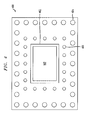
- FIG. 4 presents a bottom view 400 where chip 162 is encapsulated with encapsulant 402.
- the chip can be partially or completely encapsulated, for example, for purposes of resisting humidity.
- a plurality of outer pads 404 may correspond, for example, to attachment, heat conduction, or ground pads such as pad 130, while a plurality of inner pads 406 may correspond, for example, to signal, control, or power pads such as pad 132.
- the reflector is embedded.
- FIG. 5 shows a view 500 similar to view 400 but of a package with a reflector 144, such as in FIG. 1 . Similar items have received the same reference number and will not be described again.
- FIG. 6 shows an exemplary package 600 with a 2x2 planar phased array layout. It is possible to have more than two antennas on each row. This basic 2x2 array can be used to form much larger arrays.
- first antenna patch 104 with first feed line 114 also included are second, third and fourth antenna patches 602, 604, 606 with corresponding second, third and fourth feed lines 608, 610, 612.
- Each feed line is connected to chip 162 as described above.
- the feed lines are shown ending at the patches in FIG. 6 , it will be appreciated that they may overlap same when viewed in top or bottom plan views, and are spaced from the corresponding patch and coupling aperture when viewed in cross-section as shown in FIGS. 1-3 .
- aspects of the invention include a package with a socket for an RF chip, and a planar antenna.
- the RF chip is flip-chip attached to the package.
- Internal cavities are used to improve the patch bandwidth. Venting holes are used to remove the hot gases during the PCB manufacturing process.
- the package can be attached to the mother PCB through a BGA.
- the package can implement a planar phased array.
- radio-frequency integrated circuit chip package according to the invention is defined by independent claim 1.
- Optional features are set ou in the dependent claims.
- Non-limiting examples of materials that may be used include thermoset plastic/ceramic/woven glass or similar laminates such as the Rogers RO4000 ® series of materials (and other compatible materials) available from Rogers Corporation of Rogers, Connecticut USA, as well as copper for metal layers, possibly gold-plated on pads or other exposed areas.
- embodiments of the invention such as 100, 200, and 300, provide a complete package and not a mere patch antenna separate from the chip and other packaging.
- vias such as 124, 140 may be formed, for example, using plated through holes.
- the second substrate layer such as that formed by substrate 108 and bound films 106, 109, is interposed in a region between the ground plane 110 and a plane defined by the patch 104.
- the patch 104 is formed in a first metal layer and the ground plane 110 is formed in a second metal layer.
- the third substrate layer such as that formed by substrate 112, interposed in a region between the ground plane 110 and the feed line 114.
- the feed line 114 is formed in a third metal layer.
- one or more packages in accordance with embodiments of the invention may include at least one via, such as via 190, formed in the third substrate layer 112 and coupled to the ground plane 110.
- a plurality of chip connection pads such as pads 116, 118, 120, can be formed in the third metal layer.
- At least one of the chip connection pads, such as 118 can be coupled to the at least one via 190 in the third substrate layer.
- the chip connection pads couple the chip to the feed line 114 (pad 120), the via 190 (pad 118) and the via 124 (pad 116).
- One or more embodiments of the invention may include one or more signals pads, one or more control pads, and one or more power supply pads, all of which are exemplified by pad 132, as well as one or more ground pads, such as 130.
- the signal, control, power supply and ground pads are advantageously formed in a fourth metal layer.
- package pads 134 can optionally be provided.
- At least one ground via such as 140, coupling the ground plane 110 and the ground pad 130.
- the at least one ground via 140 passes through the first and third substrate layers (e.g., substrate 112, bound film 126, and substrate 128), in a region not intersecting the feed line 114.
- One or more embodiments include at least one each of power, signal, and control antipads, such as antipad 142, formed substantially coplanar with the ground plane 110.
- At least one signal via couples the signal antipad and the signal pad, and passes through the first and third substrate layers.
- at least one power via couples the power antipad and the power pad, and passes through the first and third substrate layers.
- At least one control via couples the control antipad and the control pad, and passes through the first and third substrate layers.
- pad 132, via 124, and antipad 142 are illustrative of pad, via, and antipad elements that may be provided for power, signal, and control functionality.
- one or more planar phased arrays are implemented.
- the above-discussed patch 104 may be designated as a first patch, and the above-discussed feed line 114 is a first feed line.
- the ground plane can be formed with one or more additional coupling aperture slots, like slot 113.
- the package can include one or more additional generally planar patches, such as patches 602, 604, 606, spaced outwardly from the ground plane.
- the additional slots can be substantially opposed to the additional patches.
- the package can also include one or more additional feed lines, such as lines 608, 610, 614, spaced inwardly from the ground plane and substantially parallel thereto.
- the at least one radio frequency chip 162 is coupled to the additional feed line(s) and the first patch and additional patch(es) are arranged to form a planar phased array.
- a single large ground plane with multiple slots can be employed in phased array embodiments.
- a phased array can include any number of patches greater than or equal to two; however, powers of two are advantageous, e.g., 2, 4, 8, 16, 32, and so on.
Landscapes
- Physics & Mathematics (AREA)
- Engineering & Computer Science (AREA)
- Microelectronics & Electronic Packaging (AREA)
- Condensed Matter Physics & Semiconductors (AREA)
- General Physics & Mathematics (AREA)
- Computer Hardware Design (AREA)
- Power Engineering (AREA)
- Electromagnetism (AREA)
- Variable-Direction Aerials And Aerial Arrays (AREA)
- Waveguide Aerials (AREA)
- Aerials With Secondary Devices (AREA)
Description
- The present invention generally relates to communications circuitry, and, more particularly, to radio frequency (RF) integrated circuit (IC) packages.
- In a wireless network, the connectivity and communication between devices is achieved through antennas attached to receivers or transmitters, in order to radiate the desired signals to or from other elements of the network. In radio communication systems, such as millimeter-wave radios, discrete components are usually assembled with low integration levels. These systems are often assembled using expensive and bulky waveguides and package-level or board-level microstrip structures to interconnect semiconductors and their required transmitter- or receiver-antennas. With recent progress in semiconductor technology and packaging engineering, the dimensions of these radio communication systems have become smaller. For applications such as wireless universal serial bus (USB), the operating distance is limited to about a meter; and a single antenna with about 7 dBi at 60 GHz will provide the necessary antenna gain. For distances as long as 10 meters (such as wireless video) or longer (such as radar), in point-to-point applications, antenna gains as high as 30 dBi, depending on the application, are required. However, high gain antennas for wireless video applications have very narrow beam widths, so pointing the antenna is very difficult for consumers. Therefore, a radiation pattern steerable array (also a phased array) is necessary. Phased arrays are also widely used in military radars. However, packaging RF chips with integrated antennas or phased arrays is extremely difficult and very expensive due to the expensive components and extensive labor involved.
- US patent application
US 2005/0048934 A1 in the name of Ranwick, James J et al. and US patent applicationUS 2004/0252058 A1 in the name of Ranwick, James J et al. disclose a dynamically reconfigurable aperture couple antenna in which input impedance of the antenna can be controlled by varying the volume or position of a conductive fluid in a region between the RF transmission line and the antenna radiating element. US patent application -
US 2007/0126641 A1 in the name of Jussi Saily discloses a dual-polarized microstrip patch antenna structure. - US patent application
US 2007/0026567 A1 in the name of Beer, Gottfried et al. discloses a semiconductor module having components for microwave engineering in a plastic casing. The semiconductor module is described as having a principal surface with an upper side of a plastic package moulding compound and at least one active upper side of a semiconductor chip. Disposed on the principal surface is a multilayered conductor track structure which alternately comprises structured metal layers and structured insulation layers, where at least one of the insulation layers and/or the plastic package moulding compound has at least one microwave insulation region. - Principles of the present invention provide techniques for implementing RF IC packages with integrated aperture-coupled patch antennas.
- Accordingly the present invention provides a radio-frequency integrated circuit chip package with at least one integrated aperture-coupled patch antenna. The package comprises at least one planar patch formed in a first metal layer; at least one planar ground plane formed in a second metal layer spaced inwardly from said planar patch and parallel thereto. The ground plane is formed with at least one coupling aperture slot therein, said slot being opposed to said patch. At least one feed line is formed in a third metal layer spaced inwardly from said ground plane and parallel thereto. At least one radio frequency chip is spaced inwardly from said feed line and coupled to said feed line and said ground plane. A first substrate layer is spaced inwardly from said feed line, said first substrate layer being formed with a chip-receiving cavity, said chip being located in said chip-receiving cavity. A second substrate layer is interposed between said ground plane and a plane defined by said patch. An additional substrate layer is located outwardly from said planar patch, wherein said patch is formed on an inner surface of said additional substrate layer. A third substrate layer is interposed between said ground plane and said feed line. A reflector spaced inwardly from said feed line, by said first substrate layer and opposed to said coupling aperture slot. An air cavity is formed in said second substrate layer, said air cavity being located between said patch and said coupling aperture slot in said ground plane, wherein said at least one planar patch is located in said air cavity. A vent hole is formed in said secondsubstrate layer or said additional substrate in communication with said air cavity.
- These and other objects, features and advantages of the present invention will become apparent from the following detailed description of illustrative embodiments thereof, which is to be read in connection with the accompanying drawings.
-
-
FIG. 1 shows an exemplary embodiment of a package, in cross section, according to an aspect of the invention; -
FIG. 2 shows an exemplary embodiment of another package, in cross section, according to another aspect of the invention; -
FIG. 3 shows an exemplary embodiment of yet another package, in cross section, according to yet another aspect of the invention; -
FIG. 4 is a bottom view of an exemplary package with no reflector or an embedded reflector; -
FIG. 5 is a bottom view of an exemplary package with a visible reflector; and -
FIG. 6 is a bottom view of an exemplary planar phased array embodiment. - One or more embodiments of the invention provide an apparatus and method for low cost packages with integrated antennas and phased arrays operating in the millimeter wave (mmWave) range. An exemplary inventive package with integrated antennas is based on a multilayer printed circuit board (PCB). The package contains multiple cavities for implementing high performance antenna(s) or antenna arrays and housing mmWave radio frequency (RF) integrated circuit chips. One or more embodiments of the invention also provide techniques to overcome the difficulties in making internal cavities and to avoid the need to employ wire bond technology at mmWave frequencies. Embodiments of the inventive packaging technology are consistent with the PCB manufacturing process and can be used for packages with an integrated antenna or antenna array.
- Instances of the invention thus provide low cost packaging with integrated antennas or planar phased arrays; in particular, chip packaging with integrated antennas or planar phased array designs for mmWave frequencies and above.
- Typical chip packages with integrated antennas have three major parts: (i) an RF chip, (ii) one or more antennas, and (iii) a package carrier (and in some instances, a package lid or cover, or an encapsulant to protect the package). One or more embodiments of the invention provide a package that has high performance antennas, an interface for flip-chipping an RF chip and an interface for flip-chipping the package to a printed circuit mother board.
-
FIG. 1 shows a cross-sectional view of anexemplary package 100, according to an aspect of the invention. Note that section lining is omitted for clarity. The package has seven total layers, including substrate and bounding layers. For mmWave applications, especially for frequencies above 60 GHz, bounding film and/or layer thickness has to be considered in the design process. Given the teachings herein, a person having ordinary skill in the antenna and packaging arts will know how to take the thickness into account and how to employ high precision PCB fabrication techniques to make embodiments of the invention. Thepackage 100 also has a number of metal layers. In particular, there is anoutermost substrate 102. Immediately inward therefrom is a metal layer used for the patch(es) 104 of the patch antenna(s). Inward of thesubstrate 102 and patch antenna 104 (only a single antenna is depicted inFIG. 1 , but more can be provided as discussed below) are abound film layer 106, anothersubstrate layer 108, and anotherbound film layer 109. Another metal layer, inward ofbound film 109, is used for theground plane 110 of the patch antenna. Slot(s) 113 on the ground plane are used for the apertures of the aperture-coupled patch antennas. Theground plane 110 also separates the radiating elements (patches) 104 from the feed line(s) and the RF chip(s), discussed below. - Another
substrate 112 is inward fromground plane 110. Another metal layer is inward fromsubstrate 112 and is used to implement the antenna feed line(s) 114,pads film layer 126 inward of the metal layer formingfeed line 114, and afurther substrate 128 inward ofbound film 126. A still further metal layer provides all the pads for signal, control, power supply, and ground connections to the mother PCB (the mother PCB is omitted from the figure for clarity). Pads may includeground pad 130 interconnected withground plane 110 through ground via 140, as well as one or more of signal, power, and control pads exemplified bypad 132 connected tointerconnection 122 andantipad 142 by via 124. The vias may be, for example, plated through holes.Package pads 134 may also be provided. Areflector 144 is also implemented on the same metal layer as thepads reflector 144 is embedded. - To implement the flip-chip approach, the
chip 162 preferably has a plurality of solder dots connected directly to thechip connection pads - To enhance the patch antenna bandwidth, patches may be air suspended or supported with a foam material with a dielectric constant close to one at low frequency applications. However, at mmWave frequencies, especially for package applications, air suspended or foam supported patches are not realistic. Thus, in accordance with the invention, an
air cavity 150 is implemented in the packages. To avoid issues from hot gases during the PCB manufacturing process, vent hole(s) 152 are employed. These holes can be designed such that they have little effect on the antenna performance. For example,hole 152 can be located near the middle of thecavity 150 or close to the edge of thecavity 150, and can be made relatively small, consistent with adequate venting. The vent holes can be on the top (outermost part of) thecavity 150 as shown inFIG. 1 or on the side of the cavity as discussed below, depending on the manufacturing process used. - The
ground plane 110 is also used for making ground connections through vias (e.g., via 140) and signal, power, and control connections through vias and antipads (e.g., via 124 withantipad 142, illustrative of a via with antipad that could be used for signal, power, or control functionality). Antipads are beneficial from a manufacturing standpoint, and result in increased reliability, as it is difficult to achieve reliability in partial vias (i.e., vias such as via 124 that do not extend completely through a structure) without use of antipads. - An open chip-receiving cavity or
socket 160 is realized in thesubstrate 128 and boundfilm 126. This socket is used to hold theRF chip 162. The chip is attached to the package through flip-chip bonding. - Note that all the mmWave components (antennas, power amplifiers, low noise amplifiers, and the like) are in the
package 100.Vias - The
package 100 may advantageously be attached to the mother board (not shown) through a ball grid array (BGA). -
FIG. 2 shows an embodiment substantially similar toembodiment 100 except thatreflector 144 is encapsulated by an additional boundlayer 170 inward ofreflector 144 and anadditional substrate 172 inward of boundlayer 170. Similar items have received the same reference number and will not be described again. Chip receivingsocket 160 is also formed insubstrate 172 and boundlayer 170 in this embodiment. -
FIG. 3 shows an embodiment substantially similar toembodiment 200 except that vent 352 runs sideways throughlayer 108 so as to ventcavity 150. Similar items have received the same reference number and will not be described again. -
FIG. 4 presents abottom view 400 wherechip 162 is encapsulated withencapsulant 402. The chip can be partially or completely encapsulated, for example, for purposes of resisting humidity. A plurality ofouter pads 404 may correspond, for example, to attachment, heat conduction, or ground pads such aspad 130, while a plurality ofinner pads 406 may correspond, for example, to signal, control, or power pads such aspad 132. InFIG. 4 , the reflector is embedded.FIG. 5 shows aview 500 similar to view 400 but of a package with areflector 144, such as inFIG. 1 . Similar items have received the same reference number and will not be described again. -
FIG. 6 shows anexemplary package 600 with a 2x2 planar phased array layout. It is possible to have more than two antennas on each row. This basic 2x2 array can be used to form much larger arrays. In addition tofirst antenna patch 104 withfirst feed line 114, also included are second, third andfourth antenna patches fourth feed lines FIG. 6 , it will be appreciated that they may overlap same when viewed in top or bottom plan views, and are spaced from the corresponding patch and coupling aperture when viewed in cross-section as shown inFIGS. 1-3 . - It will thus be appreciated that aspects of the invention include a package with a socket for an RF chip, and a planar antenna. In one or more instances, the RF chip is flip-chip attached to the package. Internal cavities are used to improve the patch bandwidth. Venting holes are used to remove the hot gases during the PCB manufacturing process. The package can be attached to the mother PCB through a BGA. The package can implement a planar phased array.
- In view of the discussion of
FIGS. 1-6 , it will be appreciated that, in general terms, the radio-frequency integrated circuit chip package according to the invention is defined by independent claim 1. Optional features are set ou in the dependent claims. - Non-limiting examples of materials that may be used include thermoset plastic/ceramic/woven glass or similar laminates such as the Rogers RO4000® series of materials (and other compatible materials) available from Rogers Corporation of Rogers, Connecticut USA, as well as copper for metal layers, possibly gold-plated on pads or other exposed areas.
- It will be appreciated that advantageously, embodiments of the invention, such as 100, 200, and 300, provide a complete package and not a mere patch antenna separate from the chip and other packaging.
- Note that vias such as 124, 140 may be formed, for example, using plated through holes.
- The second substrate layer, such as that formed by
substrate 108 and boundfilms ground plane 110 and a plane defined by thepatch 104. Thepatch 104 is formed in a first metal layer and theground plane 110 is formed in a second metal layer. - The third substrate layer, such as that formed by
substrate 112, interposed in a region between theground plane 110 and thefeed line 114. Thefeed line 114 is formed in a third metal layer. Further, one or more packages in accordance with embodiments of the invention may include at least one via, such as via 190, formed in thethird substrate layer 112 and coupled to theground plane 110. A plurality of chip connection pads, such aspads - One or more embodiments of the invention may include one or more signals pads, one or more control pads, and one or more power supply pads, all of which are exemplified by
pad 132, as well as one or more ground pads, such as 130. The signal, control, power supply and ground pads are advantageously formed in a fourth metal layer. As noted,package pads 134 can optionally be provided. - Also included in one or more embodiments is at least one ground via, such as 140, coupling the
ground plane 110 and theground pad 130. The at least one ground via 140 passes through the first and third substrate layers (e.g.,substrate 112, boundfilm 126, and substrate 128), in a region not intersecting thefeed line 114. One or more embodiments include at least one each of power, signal, and control antipads, such asantipad 142, formed substantially coplanar with theground plane 110. At least one signal via couples the signal antipad and the signal pad, and passes through the first and third substrate layers. Similarly, at least one power via couples the power antipad and the power pad, and passes through the first and third substrate layers. Furthermore, at least one control via couples the control antipad and the control pad, and passes through the first and third substrate layers. As noted,pad 132, via 124, andantipad 142 are illustrative of pad, via, and antipad elements that may be provided for power, signal, and control functionality. As noted with regard toFIG. 6 , in one or more embodiments of the invention, one or more planar phased arrays are implemented. Thus, in general terms, the above-discussedpatch 104 may be designated as a first patch, and the above-discussedfeed line 114 is a first feed line. The ground plane can be formed with one or more additional coupling aperture slots, likeslot 113. The package can include one or more additional generally planar patches, such aspatches lines radio frequency chip 162 is coupled to the additional feed line(s) and the first patch and additional patch(es) are arranged to form a planar phased array. A single large ground plane with multiple slots can be employed in phased array embodiments. A phased array can include any number of patches greater than or equal to two; however, powers of two are advantageous, e.g., 2, 4, 8, 16, 32, and so on.
Claims (9)
- A radio-frequency integrated circuit chip package (100) with at least one integrated aperture-coupled patch antenna, said package comprising:at least one planar patch (104) formed in a first metal layer;at least one planar ground plane (110) formed in a second metal layer spaced inwardly from said planar patch (104) and parallel thereto, said ground plane (110) being formed with at least one coupling aperture slot (113) therein, said slot (113) being opposed to said patch (104);at least one feed line (114) formed in a third metal layer spaced inwardly from said ground plane (110) and parallel thereto;at least one radio frequency chip (162) spaced inwardly from said feed line (114) and coupled to said feed line (114) and said ground plane (110);a first substrate layer (126, 128) spaced inwardly from said feed line (114), said first substrate layer (126, 128) being formed with a chip-receiving cavity (160), said chip (162) being located in said chip-receiving cavity (160);a second substrate layer (106,108,109) interposed between said ground plane (110) and a plane defined by said patch (104);a third substrate layer (112) interposed between said ground plane (110) and said feed line (114);a reflector (144) spaced inwardly from said feed line (114), by said first substrate layer (126, 128) and opposed to said coupling aperture slot (113);characterised by further comprising:an additional substrate layer (102) located outwardly from said at least one planar patch (104),wherein said at least one planar patch (104) is formed on an inner surface of said additional substrate layer; an air cavity (150) formed in said second substrate layer (106,108,1 09) between said patch (104) and said coupling aperture slot (113) with said planar patch (104) being located in said air cavity (150); anda vent hole (152, 352) formed in said second substrate layer (106,108,109) or said additional substrate (102) in communication with said air cavity (150) , so as to vent said cavity (150).
- The package of Claim 1, further comprising:at least one via (124,140,190) formed in said third substrate layer (112) and coupled to said ground plane (110); anda plurality of chip connection pads (116,118,120) formed in said third metal layer), at least one of said chip connection pads (118) being coupled to said at least one via (190) in said third substrate layer (112), said chip connection pads (118,120) coupling said chip (162) to said feed line (114) and said at least one via (190) in said third substrate layer (112).
- The package of Claim 2, further comprising:at least one signal pad (132);at least one control pad (132);at least one power supply pad (132); andat least one ground pad (130);wherein said signal (132), control (132), power supply (132) and ground (130) pads are formed in a fourth metal layer.
- The package of Claim 3, further comprising:at least one ground via (140) coupling said ground plane (110) and said ground pad (130), said at least one ground via (140) passing through said first (126,128) and third (112) substrate layers, in a region not intersecting said feed line (114);at least power, signal, and control antipads (142) formed substantially coplanar with said ground plane (110);at least one signal via (124) coupling said signal antipad (142) and said signal pad (132), said at least one signal via (124) passing through said first (126,128) and third (112) substrate layers;at least one power via (124) coupling said power antipad (142) and said power pad (132), said at least one power via (124) passing through said first (126,128) and third (112) substrate layers; andat least one control via (124) coupling said control antipad (142) and said control pad (132), said at least one control via (124) passing through said first (126,128) and third (112) substrate layers.
- The package of Claim 1 wherein said reflector (144) is located on an inner surface of said first substrate layer (126,128).
- The package of Claim 5, further comprising a fourth substrate layer (170,172) spaced inwardly from said reflector (144), said reflector (144) being embedded between said first (126,128) and fourth (170,172) substrate layers.
- The package of Claim 1, wherein said vent (152) is formed in said additional substrate (102).
- The package of Claim 1, wherein said vent (352) is formed in said second substrate layer (106,108,109).
- The package of Claim 1, wherein:said at least one patch (104) is a first patch (104);said at least one feed line (114) is a first feed line (114); andsaid ground plane (110) is formed with at least a second coupling aperture slot;said package further comprising:at least a second generally planar patch (602,604,606) spaced outwardly from said ground plane (110), said second slot being substantially opposed to said second patch (602,604,606); andat least a second feed line (608,610,612) spaced inwardly from said ground plane (110) and substantially parallel thereto;wherein said at least one radio frequency chip (162) is coupled to said second feed line (608,610,612) and wherein said first (104) and second (602,604,606) patches are arranged to form a planar phased array.
Applications Claiming Priority (2)
| Application Number | Priority Date | Filing Date | Title |
|---|---|---|---|
| US12/034,023 US7692590B2 (en) | 2008-02-20 | 2008-02-20 | Radio frequency (RF) integrated circuit (IC) packages with integrated aperture-coupled patch antenna(s) |
| PCT/US2008/088516 WO2009105146A1 (en) | 2008-02-20 | 2008-12-30 | Radio frequency (rf) integrated circuit (ic) packages with integrated aperture-coupled patch antenna(s) |
Publications (3)
| Publication Number | Publication Date |
|---|---|
| EP2253045A1 EP2253045A1 (en) | 2010-11-24 |
| EP2253045A4 EP2253045A4 (en) | 2011-03-23 |
| EP2253045B1 true EP2253045B1 (en) | 2015-03-25 |
Family
ID=40954643
Family Applications (1)
| Application Number | Title | Priority Date | Filing Date |
|---|---|---|---|
| EP08872709.4A Active EP2253045B1 (en) | 2008-02-20 | 2008-12-30 | Radio frequency (rf) integrated circuit (ic) packages with integrated aperture-coupled patch antenna(s) |
Country Status (6)
| Country | Link |
|---|---|
| US (1) | US7692590B2 (en) |
| EP (1) | EP2253045B1 (en) |
| JP (1) | JP5285089B2 (en) |
| KR (1) | KR101397748B1 (en) |
| TW (1) | TWI463736B (en) |
| WO (1) | WO2009105146A1 (en) |
Families Citing this family (42)
| Publication number | Priority date | Publication date | Assignee | Title |
|---|---|---|---|---|
| US7830312B2 (en) | 2008-03-11 | 2010-11-09 | Intel Corporation | Wireless antenna array system architecture and methods to achieve 3D beam coverage |
| US20110163921A1 (en) * | 2010-01-06 | 2011-07-07 | Psion Teklogix Inc. | Uhf rfid internal antenna for handheld terminals |
| US8558637B2 (en) | 2010-05-12 | 2013-10-15 | Mediatek Inc. | Circuit device with signal line transition element |
| US8766867B2 (en) | 2010-12-16 | 2014-07-01 | Sony Corporation | Compact antenna for multiple input multiple output communications including isolated antenna elements |
| US8587482B2 (en) | 2011-01-21 | 2013-11-19 | International Business Machines Corporation | Laminated antenna structures for package applications |
| KR101891084B1 (en) | 2012-05-23 | 2018-08-24 | 삼성전자주식회사 | Aperture-coupled microstrip antenna and manufacturing method thereof |
| TWI528468B (en) | 2012-05-30 | 2016-04-01 | 國立中山大學 | A mimo antenna, antenna unit thereof and a system in package having said antenna |
| KR102193134B1 (en) | 2013-10-14 | 2020-12-21 | 삼성전자주식회사 | Wearable body sensing device and system including the same |
| US9917372B2 (en) * | 2014-06-13 | 2018-03-13 | Nxp Usa, Inc. | Integrated circuit package with radio frequency coupling arrangement |
| US10103447B2 (en) | 2014-06-13 | 2018-10-16 | Nxp Usa, Inc. | Integrated circuit package with radio frequency coupling structure |
| US10225925B2 (en) | 2014-08-29 | 2019-03-05 | Nxp Usa, Inc. | Radio frequency coupling and transition structure |
| US9548551B1 (en) * | 2015-08-24 | 2017-01-17 | International Business Machines Corporation | DIMM connector region vias and routing |
| US10327268B2 (en) * | 2015-09-25 | 2019-06-18 | Intel Corporation | Microelectronic package with wireless interconnect |
| CN110600872B (en) * | 2016-01-30 | 2023-09-12 | 华为技术有限公司 | Patch antenna unit and antenna |
| US9913376B2 (en) | 2016-05-04 | 2018-03-06 | Northrop Grumman Systems Corporation | Bridging electronic inter-connector and corresponding connection method |
| CN107864688B (en) * | 2016-07-22 | 2019-12-31 | 京瓷株式会社 | Substrate for RFID tag, and RFID system |
| US11239186B2 (en) * | 2016-09-23 | 2022-02-01 | Intel Corporation | Die with embedded communication cavity |
| KR102617831B1 (en) * | 2016-09-26 | 2023-12-27 | 인텔 코포레이션 | Die with embedded communication cavity |
| US10639462B2 (en) | 2016-10-18 | 2020-05-05 | Acclarent, Inc. | Dilation system |
| CN108235792B (en) * | 2016-10-21 | 2021-01-26 | 京瓷株式会社 | Substrate for tag, RFID tag, and RFID system |
| KR102362243B1 (en) * | 2017-10-18 | 2022-02-11 | 삼성전자주식회사 | Radio frequency package module and electronic apparatus including the same |
| US10700410B2 (en) | 2017-10-27 | 2020-06-30 | Mediatek Inc. | Antenna-in-package with better antenna performance |
| US10993315B2 (en) * | 2017-10-31 | 2021-04-27 | Avl Technologies, Inc. | Printed circuit via for KA satcom circuit boards |
| KR102022353B1 (en) | 2018-01-18 | 2019-09-18 | 삼성전기주식회사 | Antenna module |
| US11380979B2 (en) | 2018-03-29 | 2022-07-05 | Intel Corporation | Antenna modules and communication devices |
| CN110401005B (en) * | 2018-04-24 | 2021-01-29 | 华为技术有限公司 | Packaged antenna, preparation method thereof and mobile communication terminal |
| US11509037B2 (en) * | 2018-05-29 | 2022-11-22 | Intel Corporation | Integrated circuit packages, antenna modules, and communication devices |
| CN109037932B (en) * | 2018-07-16 | 2021-01-01 | 南通大学 | Broadband multi-patch antenna |
| TWI693679B (en) * | 2018-08-07 | 2020-05-11 | 矽品精密工業股份有限公司 | Electronic package |
| US11329396B2 (en) | 2018-10-18 | 2022-05-10 | Amotech Co., Ltd. | Antenna package having cavity structure |
| CN109285828B (en) * | 2018-12-06 | 2023-09-08 | 盛合晶微半导体(江阴)有限公司 | Fan-out antenna packaging structure with air cavity and preparation method thereof |
| CN110010600B (en) * | 2018-12-31 | 2020-12-29 | 浙江臻镭科技股份有限公司 | Interconnection structure for vertically placing radio frequency chip module and manufacturing method thereof |
| CN111725623A (en) * | 2019-03-20 | 2020-09-29 | 三星电机株式会社 | Chip antenna module and electronic device |
| CN111755805B (en) * | 2019-03-28 | 2022-02-18 | Oppo广东移动通信有限公司 | Antenna module and electronic equipment |
| US11417959B2 (en) * | 2019-04-11 | 2022-08-16 | Samsung Electro-Mechanics Co., Ltd. | Chip antenna module and electronic device |
| US11431107B2 (en) | 2019-04-11 | 2022-08-30 | Samsung Electro-Mechanics Co., Ltd. | Chip antenna module and method of manufacturing chip antenna module |
| KR102639685B1 (en) * | 2019-05-17 | 2024-02-23 | 삼성전자주식회사 | Electronic device comprising antenna module |
| CN111987088B (en) * | 2019-05-23 | 2022-07-29 | 中国科学院微电子研究所 | Organic substrate embedding packaging structure integrating antenna and radio frequency front end |
| CN110444532A (en) * | 2019-07-17 | 2019-11-12 | 中电国基南方集团有限公司 | A kind of V-band Small aperture coupling type of HTCC technique is without lead Surface Mount shell |
| CN111653527B (en) * | 2020-06-15 | 2023-03-28 | 华进半导体封装先导技术研发中心有限公司 | Packaged antenna and method of manufacturing the same |
| CN112397477B (en) * | 2020-11-17 | 2023-03-21 | 成都仕芯半导体有限公司 | Millimeter wave chip packaging system |
| CN112531339B (en) * | 2020-12-11 | 2022-04-15 | 安徽大学 | Millimeter wave broadband packaged antenna based on Fan-out packaging technology |
Family Cites Families (22)
| Publication number | Priority date | Publication date | Assignee | Title |
|---|---|---|---|---|
| JPH0590803A (en) * | 1991-09-30 | 1993-04-09 | Toshiba Corp | Multilayer microwave circuit |
| JP3141692B2 (en) * | 1994-08-11 | 2001-03-05 | 松下電器産業株式会社 | Millimeter wave detector |
| JP3194468B2 (en) * | 1995-05-29 | 2001-07-30 | 日本電信電話株式会社 | Microstrip antenna |
| JP3427040B2 (en) * | 1996-02-29 | 2003-07-14 | 京セラ株式会社 | High frequency package |
| JP3426104B2 (en) * | 1997-05-13 | 2003-07-14 | 日立粉末冶金株式会社 | Thin plate component for semiconductor package and method of manufacturing the same |
| EP1126522A1 (en) * | 2000-02-18 | 2001-08-22 | Alcatel | Packaged integrated circuit with radio frequency antenna |
| WO2001084313A2 (en) | 2000-05-02 | 2001-11-08 | Sun Microsystems, Inc. | Method and system for achieving high availability in a networked computer system |
| US6809688B2 (en) | 2000-06-30 | 2004-10-26 | Sharp Kabushiki Kaisha | Radio communication device with integrated antenna, transmitter, and receiver |
| EP1540729A1 (en) | 2002-09-17 | 2005-06-15 | Axalto SA | Method of manufacturing a wafer assembly |
| AU2002340506A1 (en) | 2002-11-07 | 2004-06-07 | Fractus, S.A. | Integrated circuit package including miniature antenna |
| US6906668B2 (en) * | 2003-06-11 | 2005-06-14 | Harris Corporation | Dynamically reconfigurable aperture coupled antenna |
| US7084828B2 (en) * | 2003-08-27 | 2006-08-01 | Harris Corporation | Shaped ground plane for dynamically reconfigurable aperture coupled antenna |
| US7030706B2 (en) | 2003-12-05 | 2006-04-18 | Elite Semiconductor Memory Technology, Inc. | Self-calibratable oscillating device and method and ASIC thereof |
| JP4335661B2 (en) * | 2003-12-24 | 2009-09-30 | Necエレクトロニクス株式会社 | Manufacturing method of high frequency module |
| US7119745B2 (en) | 2004-06-30 | 2006-10-10 | International Business Machines Corporation | Apparatus and method for constructing and packaging printed antenna devices |
| US7312763B2 (en) | 2004-07-23 | 2007-12-25 | Farrokh Mohamadi | Wafer scale beam forming antenna module with distributed amplification |
| WO2006137926A2 (en) | 2004-11-02 | 2006-12-28 | Nantero, Inc. | Nanotube esd protective devices and corresponding nonvolatile and volatile nanotube switches |
| US20060151869A1 (en) * | 2005-01-10 | 2006-07-13 | Franz Gisin | Printed circuit boards and the like with improved signal integrity for differential signal pairs |
| US7321339B2 (en) | 2005-01-14 | 2008-01-22 | Farrokh Mohamadi | Phase shifters for beamforming applications |
| DE102006023123B4 (en) * | 2005-06-01 | 2011-01-13 | Infineon Technologies Ag | Distance detection radar for vehicles with a semiconductor module with components for high frequency technology in plastic housing and method for producing a semiconductor module with components for a distance detection radar for vehicles in a plastic housing |
| FI20055637A0 (en) | 2005-12-02 | 2005-12-02 | Nokia Corp | Kaksipolarisaatio-microstrip patch antenna structure |
| US7518229B2 (en) | 2006-08-03 | 2009-04-14 | International Business Machines Corporation | Versatile Si-based packaging with integrated passive components for mmWave applications |
-
2008
- 2008-02-20 US US12/034,023 patent/US7692590B2/en active Active
- 2008-12-30 EP EP08872709.4A patent/EP2253045B1/en active Active
- 2008-12-30 KR KR1020107018112A patent/KR101397748B1/en active IP Right Grant
- 2008-12-30 WO PCT/US2008/088516 patent/WO2009105146A1/en active Application Filing
- 2008-12-30 JP JP2010547614A patent/JP5285089B2/en active Active
-
2009
- 2009-02-17 TW TW098104936A patent/TWI463736B/en active
Also Published As
| Publication number | Publication date |
|---|---|
| EP2253045A4 (en) | 2011-03-23 |
| US7692590B2 (en) | 2010-04-06 |
| JP5285089B2 (en) | 2013-09-11 |
| EP2253045A1 (en) | 2010-11-24 |
| JP2011512771A (en) | 2011-04-21 |
| TWI463736B (en) | 2014-12-01 |
| US20090207080A1 (en) | 2009-08-20 |
| WO2009105146A1 (en) | 2009-08-27 |
| TW200952251A (en) | 2009-12-16 |
| KR101397748B1 (en) | 2014-05-20 |
| KR20100120661A (en) | 2010-11-16 |
Similar Documents
| Publication | Publication Date | Title |
|---|---|---|
| EP2253045B1 (en) | Radio frequency (rf) integrated circuit (ic) packages with integrated aperture-coupled patch antenna(s) | |
| CA2713353C (en) | Radio frequency (rf) integrated circuit (ic) packages with integrated aperture-coupled patch antenna(s) in ring and/or offset cavities | |
| EP2144329B1 (en) | Radio frequency integrated circuit packages | |
| US10431892B2 (en) | Antenna-in-package structures with broadside and end-fire radiations | |
| US8256685B2 (en) | Compact millimeter wave packages with integrated antennas | |
| US8269671B2 (en) | Simple radio frequency integrated circuit (RFIC) packages with integrated antennas | |
| US9196951B2 (en) | Millimeter-wave radio frequency integrated circuit packages with integrated antennas | |
| US8587482B2 (en) | Laminated antenna structures for package applications | |
| US9172132B2 (en) | Integrated antenna for RFIC package applications | |
| US9819098B2 (en) | Antenna-in-package structures with broadside and end-fire radiations | |
| US8558637B2 (en) | Circuit device with signal line transition element | |
| US20230092161A1 (en) | Phased array millimeter-wave ring antenna embedded in printed circuit board with ultra wide-band performance |
Legal Events
| Date | Code | Title | Description |
|---|---|---|---|
| PUAI | Public reference made under article 153(3) epc to a published international application that has entered the european phase |
Free format text: ORIGINAL CODE: 0009012 |
|
| 17P | Request for examination filed |
Effective date: 20100910 |
|
| AK | Designated contracting states |
Kind code of ref document: A1 Designated state(s): AT BE BG CH CY CZ DE DK EE ES FI FR GB GR HR HU IE IS IT LI LT LU LV MC MT NL NO PL PT RO SE SI SK TR |
|
| AX | Request for extension of the european patent |
Extension state: AL BA MK RS |
|
| A4 | Supplementary search report drawn up and despatched |
Effective date: 20110222 |
|
| RIC1 | Information provided on ipc code assigned before grant |
Ipc: H01Q 9/04 20060101ALI20110216BHEP Ipc: H01Q 1/38 20060101AFI20090914BHEP |
|
| DAX | Request for extension of the european patent (deleted) | ||
| REG | Reference to a national code |
Ref country code: DE Ref legal event code: R079 Ref document number: 602008037371 Country of ref document: DE Free format text: PREVIOUS MAIN CLASS: H01Q0001380000 Ipc: H01L0023660000 |
|
| RIC1 | Information provided on ipc code assigned before grant |
Ipc: H01L 23/66 20060101AFI20140630BHEP Ipc: H01Q 1/38 20060101ALI20140630BHEP Ipc: H01Q 9/04 20060101ALI20140630BHEP Ipc: H01Q 23/00 20060101ALI20140630BHEP Ipc: H01Q 1/22 20060101ALI20140630BHEP |
|
| GRAP | Despatch of communication of intention to grant a patent |
Free format text: ORIGINAL CODE: EPIDOSNIGR1 |
|
| INTG | Intention to grant announced |
Effective date: 20141222 |
|
| GRAS | Grant fee paid |
Free format text: ORIGINAL CODE: EPIDOSNIGR3 |
|
| GRAA | (expected) grant |
Free format text: ORIGINAL CODE: 0009210 |
|
| AK | Designated contracting states |
Kind code of ref document: B1 Designated state(s): AT BE BG CH CY CZ DE DK EE ES FI FR GB GR HR HU IE IS IT LI LT LU LV MC MT NL NO PL PT RO SE SI SK TR |
|
| REG | Reference to a national code |
Ref country code: GB Ref legal event code: FG4D |
|
| REG | Reference to a national code |
Ref country code: CH Ref legal event code: EP |
|
| REG | Reference to a national code |
Ref country code: CH Ref legal event code: NV Representative=s name: IBM RESEARCH GMBH ZURICH RESEARCH LABORATORY I, CH |
|
| REG | Reference to a national code |
Ref country code: IE Ref legal event code: FG4D |
|
| REG | Reference to a national code |
Ref country code: DE Ref legal event code: R096 Ref document number: 602008037371 Country of ref document: DE Effective date: 20150430 |
|
| REG | Reference to a national code |
Ref country code: AT Ref legal event code: REF Ref document number: 718303 Country of ref document: AT Kind code of ref document: T Effective date: 20150515 |
|
| PG25 | Lapsed in a contracting state [announced via postgrant information from national office to epo] |
Ref country code: LT Free format text: LAPSE BECAUSE OF FAILURE TO SUBMIT A TRANSLATION OF THE DESCRIPTION OR TO PAY THE FEE WITHIN THE PRESCRIBED TIME-LIMIT Effective date: 20150325 Ref country code: HR Free format text: LAPSE BECAUSE OF FAILURE TO SUBMIT A TRANSLATION OF THE DESCRIPTION OR TO PAY THE FEE WITHIN THE PRESCRIBED TIME-LIMIT Effective date: 20150325 Ref country code: SE Free format text: LAPSE BECAUSE OF FAILURE TO SUBMIT A TRANSLATION OF THE DESCRIPTION OR TO PAY THE FEE WITHIN THE PRESCRIBED TIME-LIMIT Effective date: 20150325 Ref country code: FI Free format text: LAPSE BECAUSE OF FAILURE TO SUBMIT A TRANSLATION OF THE DESCRIPTION OR TO PAY THE FEE WITHIN THE PRESCRIBED TIME-LIMIT Effective date: 20150325 |
|
| REG | Reference to a national code |
Ref country code: AT Ref legal event code: MK05 Ref document number: 718303 Country of ref document: AT Kind code of ref document: T Effective date: 20150325 |
|
| REG | Reference to a national code |
Ref country code: LT Ref legal event code: MG4D |
|
| PG25 | Lapsed in a contracting state [announced via postgrant information from national office to epo] |
Ref country code: GR Free format text: LAPSE BECAUSE OF FAILURE TO SUBMIT A TRANSLATION OF THE DESCRIPTION OR TO PAY THE FEE WITHIN THE PRESCRIBED TIME-LIMIT Effective date: 20150626 Ref country code: LV Free format text: LAPSE BECAUSE OF FAILURE TO SUBMIT A TRANSLATION OF THE DESCRIPTION OR TO PAY THE FEE WITHIN THE PRESCRIBED TIME-LIMIT Effective date: 20150325 |
|
| PG25 | Lapsed in a contracting state [announced via postgrant information from national office to epo] |
Ref country code: NL Free format text: LAPSE BECAUSE OF FAILURE TO SUBMIT A TRANSLATION OF THE DESCRIPTION OR TO PAY THE FEE WITHIN THE PRESCRIBED TIME-LIMIT Effective date: 20150325 |
|
| PG25 | Lapsed in a contracting state [announced via postgrant information from national office to epo] |
Ref country code: EE Free format text: LAPSE BECAUSE OF FAILURE TO SUBMIT A TRANSLATION OF THE DESCRIPTION OR TO PAY THE FEE WITHIN THE PRESCRIBED TIME-LIMIT Effective date: 20150325 Ref country code: PT Free format text: LAPSE BECAUSE OF FAILURE TO SUBMIT A TRANSLATION OF THE DESCRIPTION OR TO PAY THE FEE WITHIN THE PRESCRIBED TIME-LIMIT Effective date: 20150727 Ref country code: SK Free format text: LAPSE BECAUSE OF FAILURE TO SUBMIT A TRANSLATION OF THE DESCRIPTION OR TO PAY THE FEE WITHIN THE PRESCRIBED TIME-LIMIT Effective date: 20150325 Ref country code: ES Free format text: LAPSE BECAUSE OF FAILURE TO SUBMIT A TRANSLATION OF THE DESCRIPTION OR TO PAY THE FEE WITHIN THE PRESCRIBED TIME-LIMIT Effective date: 20150325 Ref country code: RO Free format text: LAPSE BECAUSE OF FAILURE TO SUBMIT A TRANSLATION OF THE DESCRIPTION OR TO PAY THE FEE WITHIN THE PRESCRIBED TIME-LIMIT Effective date: 20150325 Ref country code: CZ Free format text: LAPSE BECAUSE OF FAILURE TO SUBMIT A TRANSLATION OF THE DESCRIPTION OR TO PAY THE FEE WITHIN THE PRESCRIBED TIME-LIMIT Effective date: 20150325 |
|
| PG25 | Lapsed in a contracting state [announced via postgrant information from national office to epo] |
Ref country code: PL Free format text: LAPSE BECAUSE OF FAILURE TO SUBMIT A TRANSLATION OF THE DESCRIPTION OR TO PAY THE FEE WITHIN THE PRESCRIBED TIME-LIMIT Effective date: 20150325 Ref country code: AT Free format text: LAPSE BECAUSE OF FAILURE TO SUBMIT A TRANSLATION OF THE DESCRIPTION OR TO PAY THE FEE WITHIN THE PRESCRIBED TIME-LIMIT Effective date: 20150325 Ref country code: IS Free format text: LAPSE BECAUSE OF FAILURE TO SUBMIT A TRANSLATION OF THE DESCRIPTION OR TO PAY THE FEE WITHIN THE PRESCRIBED TIME-LIMIT Effective date: 20150725 |
|
| REG | Reference to a national code |
Ref country code: DE Ref legal event code: R097 Ref document number: 602008037371 Country of ref document: DE |
|
| PG25 | Lapsed in a contracting state [announced via postgrant information from national office to epo] |
Ref country code: DK Free format text: LAPSE BECAUSE OF FAILURE TO SUBMIT A TRANSLATION OF THE DESCRIPTION OR TO PAY THE FEE WITHIN THE PRESCRIBED TIME-LIMIT Effective date: 20150325 |
|
| PGFP | Annual fee paid to national office [announced via postgrant information from national office to epo] |
Ref country code: GB Payment date: 20151230 Year of fee payment: 8 |
|
| PLBE | No opposition filed within time limit |
Free format text: ORIGINAL CODE: 0009261 |
|
| STAA | Information on the status of an ep patent application or granted ep patent |
Free format text: STATUS: NO OPPOSITION FILED WITHIN TIME LIMIT |
|
| 26N | No opposition filed |
Effective date: 20160105 |
|
| REG | Reference to a national code |
Ref country code: DE Ref legal event code: R081 Ref document number: 602008037371 Country of ref document: DE Owner name: GLOBALFOUNDRIES U.S. INC., SANTA CLARA, US Free format text: FORMER OWNER: INTERNATIONAL BUSINESS MACHINES CORP., ARMONK, N.Y., US Ref country code: DE Ref legal event code: R082 Ref document number: 602008037371 Country of ref document: DE Representative=s name: GRUENECKER PATENT- UND RECHTSANWAELTE PARTG MB, DE Ref country code: DE Ref legal event code: R082 Ref document number: 602008037371 Country of ref document: DE Representative=s name: RICHARDT PATENTANWAELTE PARTG MBB, DE Ref country code: DE Ref legal event code: R081 Ref document number: 602008037371 Country of ref document: DE Owner name: GLOBALFOUNDRIES INC., KY Free format text: FORMER OWNER: INTERNATIONAL BUSINESS MACHINES CORP., ARMONK, N.Y., US |
|
| PG25 | Lapsed in a contracting state [announced via postgrant information from national office to epo] |
Ref country code: IT Free format text: LAPSE BECAUSE OF FAILURE TO SUBMIT A TRANSLATION OF THE DESCRIPTION OR TO PAY THE FEE WITHIN THE PRESCRIBED TIME-LIMIT Effective date: 20150325 |
|
| REG | Reference to a national code |
Ref country code: DE Ref legal event code: R081 Ref document number: 602008037371 Country of ref document: DE Owner name: GLOBALFOUNDRIES U.S. INC., SANTA CLARA, US Free format text: FORMER OWNER: GLOBALFOUNDRIES US 2 LLC (N.D.GES.DES STAATES DELAWARE), HOPEWELL JUNCTION, N.Y., US Ref country code: DE Ref legal event code: R082 Ref document number: 602008037371 Country of ref document: DE Representative=s name: GRUENECKER PATENT- UND RECHTSANWAELTE PARTG MB, DE Ref country code: DE Ref legal event code: R081 Ref document number: 602008037371 Country of ref document: DE Owner name: GLOBALFOUNDRIES INC., KY Free format text: FORMER OWNER: GLOBALFOUNDRIES US 2 LLC (N.D.GES.DES STAATES DELAWARE), HOPEWELL JUNCTION, N.Y., US Ref country code: DE Ref legal event code: R082 Ref document number: 602008037371 Country of ref document: DE Representative=s name: RICHARDT PATENTANWAELTE PARTG MBB, DE |
|
| PG25 | Lapsed in a contracting state [announced via postgrant information from national office to epo] |
Ref country code: SI Free format text: LAPSE BECAUSE OF FAILURE TO SUBMIT A TRANSLATION OF THE DESCRIPTION OR TO PAY THE FEE WITHIN THE PRESCRIBED TIME-LIMIT Effective date: 20150325 Ref country code: BE Free format text: LAPSE BECAUSE OF NON-PAYMENT OF DUE FEES Effective date: 20151231 |
|
| PG25 | Lapsed in a contracting state [announced via postgrant information from national office to epo] |
Ref country code: LU Free format text: LAPSE BECAUSE OF FAILURE TO SUBMIT A TRANSLATION OF THE DESCRIPTION OR TO PAY THE FEE WITHIN THE PRESCRIBED TIME-LIMIT Effective date: 20151230 Ref country code: MC Free format text: LAPSE BECAUSE OF FAILURE TO SUBMIT A TRANSLATION OF THE DESCRIPTION OR TO PAY THE FEE WITHIN THE PRESCRIBED TIME-LIMIT Effective date: 20150325 |
|
| REG | Reference to a national code |
Ref country code: CH Ref legal event code: PL |
|
| PG25 | Lapsed in a contracting state [announced via postgrant information from national office to epo] |
Ref country code: BE Free format text: LAPSE BECAUSE OF FAILURE TO SUBMIT A TRANSLATION OF THE DESCRIPTION OR TO PAY THE FEE WITHIN THE PRESCRIBED TIME-LIMIT Effective date: 20150325 |
|
| REG | Reference to a national code |
Ref country code: IE Ref legal event code: MM4A |
|
| REG | Reference to a national code |
Ref country code: FR Ref legal event code: ST Effective date: 20160831 |
|
| PG25 | Lapsed in a contracting state [announced via postgrant information from national office to epo] |
Ref country code: CH Free format text: LAPSE BECAUSE OF NON-PAYMENT OF DUE FEES Effective date: 20151231 Ref country code: LI Free format text: LAPSE BECAUSE OF NON-PAYMENT OF DUE FEES Effective date: 20151231 Ref country code: IE Free format text: LAPSE BECAUSE OF NON-PAYMENT OF DUE FEES Effective date: 20151230 |
|
| PG25 | Lapsed in a contracting state [announced via postgrant information from national office to epo] |
Ref country code: FR Free format text: LAPSE BECAUSE OF NON-PAYMENT OF DUE FEES Effective date: 20151231 |
|
| PG25 | Lapsed in a contracting state [announced via postgrant information from national office to epo] |
Ref country code: HU Free format text: LAPSE BECAUSE OF FAILURE TO SUBMIT A TRANSLATION OF THE DESCRIPTION OR TO PAY THE FEE WITHIN THE PRESCRIBED TIME-LIMIT; INVALID AB INITIO Effective date: 20081230 Ref country code: BG Free format text: LAPSE BECAUSE OF FAILURE TO SUBMIT A TRANSLATION OF THE DESCRIPTION OR TO PAY THE FEE WITHIN THE PRESCRIBED TIME-LIMIT Effective date: 20150325 Ref country code: NO Free format text: LAPSE BECAUSE OF FAILURE TO SUBMIT A TRANSLATION OF THE DESCRIPTION OR TO PAY THE FEE WITHIN THE PRESCRIBED TIME-LIMIT Effective date: 20150625 |
|
| PG25 | Lapsed in a contracting state [announced via postgrant information from national office to epo] |
Ref country code: CY Free format text: LAPSE BECAUSE OF FAILURE TO SUBMIT A TRANSLATION OF THE DESCRIPTION OR TO PAY THE FEE WITHIN THE PRESCRIBED TIME-LIMIT Effective date: 20150325 |
|
| GBPC | Gb: european patent ceased through non-payment of renewal fee |
Effective date: 20161230 |
|
| PG25 | Lapsed in a contracting state [announced via postgrant information from national office to epo] |
Ref country code: TR Free format text: LAPSE BECAUSE OF FAILURE TO SUBMIT A TRANSLATION OF THE DESCRIPTION OR TO PAY THE FEE WITHIN THE PRESCRIBED TIME-LIMIT Effective date: 20150325 Ref country code: MT Free format text: LAPSE BECAUSE OF FAILURE TO SUBMIT A TRANSLATION OF THE DESCRIPTION OR TO PAY THE FEE WITHIN THE PRESCRIBED TIME-LIMIT Effective date: 20150325 |
|
| PG25 | Lapsed in a contracting state [announced via postgrant information from national office to epo] |
Ref country code: GB Free format text: LAPSE BECAUSE OF NON-PAYMENT OF DUE FEES Effective date: 20161230 |
|
| REG | Reference to a national code |
Ref country code: DE Ref legal event code: R082 Ref document number: 602008037371 Country of ref document: DE Representative=s name: GRUENECKER PATENT- UND RECHTSANWAELTE PARTG MB, DE Ref country code: DE Ref legal event code: R081 Ref document number: 602008037371 Country of ref document: DE Owner name: GLOBALFOUNDRIES U.S. INC., SANTA CLARA, US Free format text: FORMER OWNER: GLOBALFOUNDRIES INC., GRAND CAYMAN, KY |
|
| P01 | Opt-out of the competence of the unified patent court (upc) registered |
Effective date: 20230412 |
|
| PGFP | Annual fee paid to national office [announced via postgrant information from national office to epo] |
Ref country code: DE Payment date: 20231107 Year of fee payment: 16 |