EP2249378B1 - Method for cleaning stage - Google Patents
Method for cleaning stage Download PDFInfo
- Publication number
- EP2249378B1 EP2249378B1 EP09821404.2A EP09821404A EP2249378B1 EP 2249378 B1 EP2249378 B1 EP 2249378B1 EP 09821404 A EP09821404 A EP 09821404A EP 2249378 B1 EP2249378 B1 EP 2249378B1
- Authority
- EP
- European Patent Office
- Prior art keywords
- stage
- movable stage
- movable
- pressure
- floating height
- Prior art date
- Legal status (The legal status is an assumption and is not a legal conclusion. Google has not performed a legal analysis and makes no representation as to the accuracy of the status listed.)
- Active
Links
- 238000004140 cleaning Methods 0.000 title claims description 67
- 238000000034 method Methods 0.000 title claims description 65
- 239000002245 particle Substances 0.000 claims description 83
- 238000007667 floating Methods 0.000 claims description 25
- 238000005086 pumping Methods 0.000 claims description 21
- 238000005096 rolling process Methods 0.000 claims description 21
- 230000008859 change Effects 0.000 claims description 11
- 230000001105 regulatory effect Effects 0.000 claims description 7
- 230000008569 process Effects 0.000 description 36
- 238000010894 electron beam technology Methods 0.000 description 32
- 230000033001 locomotion Effects 0.000 description 28
- 239000000758 substrate Substances 0.000 description 17
- 238000001514 detection method Methods 0.000 description 9
- 238000010586 diagram Methods 0.000 description 6
- 230000007246 mechanism Effects 0.000 description 4
- 238000007493 shaping process Methods 0.000 description 4
- 230000015556 catabolic process Effects 0.000 description 3
- 238000006731 degradation reaction Methods 0.000 description 3
- MCMNRKCIXSYSNV-UHFFFAOYSA-N Zirconium dioxide Chemical compound O=[Zr]=O MCMNRKCIXSYSNV-UHFFFAOYSA-N 0.000 description 2
- 230000009471 action Effects 0.000 description 2
- 230000002411 adverse Effects 0.000 description 2
- 230000004075 alteration Effects 0.000 description 2
- 239000000919 ceramic Substances 0.000 description 2
- 230000001276 controlling effect Effects 0.000 description 2
- 238000007599 discharging Methods 0.000 description 2
- 239000012530 fluid Substances 0.000 description 2
- 230000003287 optical effect Effects 0.000 description 2
- 230000002265 prevention Effects 0.000 description 2
- 230000009467 reduction Effects 0.000 description 2
- 230000001133 acceleration Effects 0.000 description 1
- XAGFODPZIPBFFR-UHFFFAOYSA-N aluminium Chemical compound [Al] XAGFODPZIPBFFR-UHFFFAOYSA-N 0.000 description 1
- 229910052782 aluminium Inorganic materials 0.000 description 1
- 238000005452 bending Methods 0.000 description 1
- 238000009826 distribution Methods 0.000 description 1
- 238000005516 engineering process Methods 0.000 description 1
- 230000002706 hydrostatic effect Effects 0.000 description 1
- 230000001939 inductive effect Effects 0.000 description 1
- 230000010354 integration Effects 0.000 description 1
- 238000002955 isolation Methods 0.000 description 1
- 238000005461 lubrication Methods 0.000 description 1
- 238000000206 photolithography Methods 0.000 description 1
- 238000011084 recovery Methods 0.000 description 1
- 230000010076 replication Effects 0.000 description 1
- 239000011347 resin Substances 0.000 description 1
- 229920005989 resin Polymers 0.000 description 1
- 239000004065 semiconductor Substances 0.000 description 1
- 239000004575 stone Substances 0.000 description 1
- 230000007704 transition Effects 0.000 description 1
Images


Classifications
-
- G—PHYSICS
- G03—PHOTOGRAPHY; CINEMATOGRAPHY; ANALOGOUS TECHNIQUES USING WAVES OTHER THAN OPTICAL WAVES; ELECTROGRAPHY; HOLOGRAPHY
- G03F—PHOTOMECHANICAL PRODUCTION OF TEXTURED OR PATTERNED SURFACES, e.g. FOR PRINTING, FOR PROCESSING OF SEMICONDUCTOR DEVICES; MATERIALS THEREFOR; ORIGINALS THEREFOR; APPARATUS SPECIALLY ADAPTED THEREFOR
- G03F7/00—Photomechanical, e.g. photolithographic, production of textured or patterned surfaces, e.g. printing surfaces; Materials therefor, e.g. comprising photoresists; Apparatus specially adapted therefor
- G03F7/70—Microphotolithographic exposure; Apparatus therefor
- G03F7/708—Construction of apparatus, e.g. environment aspects, hygiene aspects or materials
- G03F7/70908—Hygiene, e.g. preventing apparatus pollution, mitigating effect of pollution or removing pollutants from apparatus
- G03F7/70925—Cleaning, i.e. actively freeing apparatus from pollutants, e.g. using plasma cleaning
-
- B—PERFORMING OPERATIONS; TRANSPORTING
- B82—NANOTECHNOLOGY
- B82Y—SPECIFIC USES OR APPLICATIONS OF NANOSTRUCTURES; MEASUREMENT OR ANALYSIS OF NANOSTRUCTURES; MANUFACTURE OR TREATMENT OF NANOSTRUCTURES
- B82Y10/00—Nanotechnology for information processing, storage or transmission, e.g. quantum computing or single electron logic
-
- B—PERFORMING OPERATIONS; TRANSPORTING
- B82—NANOTECHNOLOGY
- B82Y—SPECIFIC USES OR APPLICATIONS OF NANOSTRUCTURES; MEASUREMENT OR ANALYSIS OF NANOSTRUCTURES; MANUFACTURE OR TREATMENT OF NANOSTRUCTURES
- B82Y40/00—Manufacture or treatment of nanostructures
-
- G—PHYSICS
- G03—PHOTOGRAPHY; CINEMATOGRAPHY; ANALOGOUS TECHNIQUES USING WAVES OTHER THAN OPTICAL WAVES; ELECTROGRAPHY; HOLOGRAPHY
- G03F—PHOTOMECHANICAL PRODUCTION OF TEXTURED OR PATTERNED SURFACES, e.g. FOR PRINTING, FOR PROCESSING OF SEMICONDUCTOR DEVICES; MATERIALS THEREFOR; ORIGINALS THEREFOR; APPARATUS SPECIALLY ADAPTED THEREFOR
- G03F7/00—Photomechanical, e.g. photolithographic, production of textured or patterned surfaces, e.g. printing surfaces; Materials therefor, e.g. comprising photoresists; Apparatus specially adapted therefor
- G03F7/70—Microphotolithographic exposure; Apparatus therefor
- G03F7/70691—Handling of masks or workpieces
- G03F7/70716—Stages
-
- G—PHYSICS
- G03—PHOTOGRAPHY; CINEMATOGRAPHY; ANALOGOUS TECHNIQUES USING WAVES OTHER THAN OPTICAL WAVES; ELECTROGRAPHY; HOLOGRAPHY
- G03F—PHOTOMECHANICAL PRODUCTION OF TEXTURED OR PATTERNED SURFACES, e.g. FOR PRINTING, FOR PROCESSING OF SEMICONDUCTOR DEVICES; MATERIALS THEREFOR; ORIGINALS THEREFOR; APPARATUS SPECIALLY ADAPTED THEREFOR
- G03F7/00—Photomechanical, e.g. photolithographic, production of textured or patterned surfaces, e.g. printing surfaces; Materials therefor, e.g. comprising photoresists; Apparatus specially adapted therefor
- G03F7/70—Microphotolithographic exposure; Apparatus therefor
- G03F7/70691—Handling of masks or workpieces
- G03F7/70775—Position control, e.g. interferometers or encoders for determining the stage position
-
- G—PHYSICS
- G03—PHOTOGRAPHY; CINEMATOGRAPHY; ANALOGOUS TECHNIQUES USING WAVES OTHER THAN OPTICAL WAVES; ELECTROGRAPHY; HOLOGRAPHY
- G03F—PHOTOMECHANICAL PRODUCTION OF TEXTURED OR PATTERNED SURFACES, e.g. FOR PRINTING, FOR PROCESSING OF SEMICONDUCTOR DEVICES; MATERIALS THEREFOR; ORIGINALS THEREFOR; APPARATUS SPECIALLY ADAPTED THEREFOR
- G03F7/00—Photomechanical, e.g. photolithographic, production of textured or patterned surfaces, e.g. printing surfaces; Materials therefor, e.g. comprising photoresists; Apparatus specially adapted therefor
- G03F7/70—Microphotolithographic exposure; Apparatus therefor
- G03F7/708—Construction of apparatus, e.g. environment aspects, hygiene aspects or materials
- G03F7/70808—Construction details, e.g. housing, load-lock, seals or windows for passing light in or out of apparatus
- G03F7/70816—Bearings
-
- G—PHYSICS
- G03—PHOTOGRAPHY; CINEMATOGRAPHY; ANALOGOUS TECHNIQUES USING WAVES OTHER THAN OPTICAL WAVES; ELECTROGRAPHY; HOLOGRAPHY
- G03F—PHOTOMECHANICAL PRODUCTION OF TEXTURED OR PATTERNED SURFACES, e.g. FOR PRINTING, FOR PROCESSING OF SEMICONDUCTOR DEVICES; MATERIALS THEREFOR; ORIGINALS THEREFOR; APPARATUS SPECIALLY ADAPTED THEREFOR
- G03F7/00—Photomechanical, e.g. photolithographic, production of textured or patterned surfaces, e.g. printing surfaces; Materials therefor, e.g. comprising photoresists; Apparatus specially adapted therefor
- G03F7/70—Microphotolithographic exposure; Apparatus therefor
- G03F7/708—Construction of apparatus, e.g. environment aspects, hygiene aspects or materials
- G03F7/70908—Hygiene, e.g. preventing apparatus pollution, mitigating effect of pollution or removing pollutants from apparatus
- G03F7/70916—Pollution mitigation, i.e. mitigating effect of contamination or debris, e.g. foil traps
-
- H—ELECTRICITY
- H01—ELECTRIC ELEMENTS
- H01J—ELECTRIC DISCHARGE TUBES OR DISCHARGE LAMPS
- H01J37/00—Discharge tubes with provision for introducing objects or material to be exposed to the discharge, e.g. for the purpose of examination or processing thereof
- H01J37/30—Electron-beam or ion-beam tubes for localised treatment of objects
- H01J37/317—Electron-beam or ion-beam tubes for localised treatment of objects for changing properties of the objects or for applying thin layers thereon, e.g. for ion implantation
- H01J37/3174—Particle-beam lithography, e.g. electron beam lithography
-
- H—ELECTRICITY
- H01—ELECTRIC ELEMENTS
- H01J—ELECTRIC DISCHARGE TUBES OR DISCHARGE LAMPS
- H01J37/00—Discharge tubes with provision for introducing objects or material to be exposed to the discharge, e.g. for the purpose of examination or processing thereof
- H01J37/32—Gas-filled discharge tubes
- H01J37/32431—Constructional details of the reactor
- H01J37/32798—Further details of plasma apparatus not provided for in groups H01J37/3244 - H01J37/32788; special provisions for cleaning or maintenance of the apparatus
- H01J37/32853—Hygiene
- H01J37/32862—In situ cleaning of vessels and/or internal parts
-
- H—ELECTRICITY
- H01—ELECTRIC ELEMENTS
- H01L—SEMICONDUCTOR DEVICES NOT COVERED BY CLASS H10
- H01L21/00—Processes or apparatus adapted for the manufacture or treatment of semiconductor or solid state devices or of parts thereof
- H01L21/67—Apparatus specially adapted for handling semiconductor or electric solid state devices during manufacture or treatment thereof; Apparatus specially adapted for handling wafers during manufacture or treatment of semiconductor or electric solid state devices or components ; Apparatus not specifically provided for elsewhere
- H01L21/67005—Apparatus not specifically provided for elsewhere
- H01L21/67011—Apparatus for manufacture or treatment
- H01L21/67017—Apparatus for fluid treatment
- H01L21/67028—Apparatus for fluid treatment for cleaning followed by drying, rinsing, stripping, blasting or the like
Landscapes
- Engineering & Computer Science (AREA)
- Physics & Mathematics (AREA)
- General Physics & Mathematics (AREA)
- Health & Medical Sciences (AREA)
- Chemical & Material Sciences (AREA)
- Public Health (AREA)
- Epidemiology (AREA)
- Nanotechnology (AREA)
- Environmental & Geological Engineering (AREA)
- Life Sciences & Earth Sciences (AREA)
- Atmospheric Sciences (AREA)
- Condensed Matter Physics & Semiconductors (AREA)
- Crystallography & Structural Chemistry (AREA)
- Manufacturing & Machinery (AREA)
- Analytical Chemistry (AREA)
- Plasma & Fusion (AREA)
- Mathematical Physics (AREA)
- Theoretical Computer Science (AREA)
- Computer Hardware Design (AREA)
- Microelectronics & Electronic Packaging (AREA)
- Power Engineering (AREA)
- Container, Conveyance, Adherence, Positioning, Of Wafer (AREA)
- Exposure And Positioning Against Photoresist Photosensitive Materials (AREA)
- Electron Beam Exposure (AREA)
- Exposure Of Semiconductors, Excluding Electron Or Ion Beam Exposure (AREA)
Description
- The present invention relates to a stage cleaning method. In particular, the present invention relates to a method of cleaning a stage of a stage device having a function of efficiently cleaning a track surface of a sample stage using an air bearing in a vacuum in an electron beam exposure system or the like.
- In electron beam exposure systems and electron microscopes, a sample is exposed, observed, or measured while being mounted on a stage. For example, an electron beam exposure system performs exposure while moving a stage in accordance with exposure data so that a required position on a wafer may be exposed.
- Such stages include cross roller bearing stages. In cross roller bearing stages, rollers in a track between a movable stage and a fixed stage revolve to move the movable stage. When such stages are in use, oil for vacuum devices is applied to a track and rollers for the lubrication of the track and the prevention of particle generation.
- When such a stage with a mechanical bearing is used in a state where a particle exists on a track, the particle causes strain in the stage mechanism. Such strain degrades the accuracy of stage position detection, and makes it difficult to detect a stage position accurately. A particle does not remain at a certain place on the track but moves as the stage moves. This phenomenon hinders replication of the position change of the stage and prediction of a position to which the stage is moved to. Thus, the stage mechanism has difficulty in correcting the position of the stage. Further, in the case where oil is applied to the track, particles can be removed to a certain extent while the oil exists, but the amount of particles may rapidly increases when the oil is lost.
- In contrast to such stages using mechanical bearings, technologies using air bearings are coming to be studied and used. For example,
JP 2006-66589 A - A further stage device of this kind is disclosed in
EP 1 262 835 A2 -
US 2007/0252969 A1 describes a stage device having a stage guide including a movable slider, a fixed guide shaft for guiding the movable slider and a pressure plate provided between the movable slider and the fixed guide shaft, thereby forming two chambers arranged in horizontal direction with the pressure plate therebetween. Controlling the difference in the pressure between the chambers by introducing compressed air into one chamber while discharging compressed air from the other chamber enables the movable slider to move linearly in horizontal direction along the fixed guide shaft in a non-contact manner. - When such an air bearing is used, the degradation of accuracy of a stage caused by particles on the track of the stage can be reduced compared to when a mechanical bearing is used.
- However, the stage device cannot always prevent degradation of accuracy of the stage for any-sized particles. For example, in the case where there is a particle of a size approximately equal to the height of the non-contact portion, the particle may be entangled when the stage is moved, and the fixed member and the movable member may come into contact with each other. When such a situation arises, the attitude of the stage mounted on the movable member becomes unstable. This results in accuracy degradation.
-
US 2007/0034228 A1 discloses a device for and a method of cleaning the surfaces of a substrate as it transitions thru and between small gaps between hydrostatic bearings in non-contact manner by inducing extremely high pressures upon the substrate through various fluids. -
JP 2002-349568 A -
US 6,565,419 B1 discloses a method of removing particles from a wafer stage by applying a resin film on the stage and then collecting it therefrom after particles adhere thereto. -
US 4,956,024 describes a method for cleaning semiconductor substrate surfaces, wherein a cleaning device having a gas bearing and floating above the surface is moved relative to the surface and small particles on the surface are removed due to turbulence and eddy currents in the high velocity flow of gas in the gas bearing. - It should be noted that no techniques have been reported for removing particles in the case where a stage is moved using an air bearing mechanism in a vacuum.
- The present invention has been made in view of the above-described problems in the prior art. An object of the present invention is to provide a stage cleaning method which enables particles present on a track of a stage using an air bearing in a vacuum to be efficiently removed.
- To achieve the above-described problem in the conventional art, there is provided a stage cleaning method according to
claim 1. - In the stage cleaning method of the present invention, air supplied to the air bearing is regulated so that the width of the gap between the movable stage and the fixed stage may become smaller than that for normal use, and the movable stage is moved within the entire range of the track thereof.
- Further, stage cleaning is performed by moving the movable stage throughout the entire range of the track thereof with the width of the gap between the movable stage and the fixed stage being set to a width for normal use and with the pressure on the differential pumping portion of the air bearing being increased.
- These make it possible to remove particles present on the track of the movable stage.
- Moreover, the pitching and rolling of the movable stage are detected at predetermined positions with the width of the gap between the movable stage and the fixed stage being narrowed by regulating air supplied to the air bearing. When the pitching or rolling of the movable stage is detected, stage cleaning is performed.
- Thus, stage cleaning only needs to be carried out when necessary, and efficient stage cleaning can be performed.
-
- [
fig.1]FIG. 1 is a diagram showing the configuration of an electron beam exposure system; - [
fig.2]FIG. 2 is a block diagram showing the configuration of a sample stage device of an exposure system according toFIG. 1 ; - [
fig.3]FIGS. 3(a) to 3(c) are schematic diagrams showing the configuration of a principal part, in which an air bearing is used, of the sample stage device; - [
fig.4]FIGS. 4(a) to 4(c) are views (part 1) for explaining cleaning on the track of the sample stage device; - [
fig.5]FIG. 5 is a flowchart (part 1) showing one example of a stage cleaning process for the sample stage device; - [
fig.6]FIGS. 6(a) to 6(c) are views for explaining states in which there is a particle on the track of the sample stage device; - [
fig.7]FIG. 7 is a flowchart (part 1) showing one example of a particle detection process in the stage cleaning process for the sample stage device; - [
fig.8]FIG. 8 is a flowchart (part 2) showing one example of a particle detection process in the stage cleaning process for the sample stage device; - [
fig.9]FIGS. 9(a) to 9(c) are views (part 2) for explaining cleaning on the track of the sample stage device; - [
fig.10]FIG. 10 is a flowchart (part 2) showing one example of a stage cleaning process for the sample stage device; - [
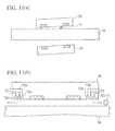
fig.11]FIGS. 11(a) and 11(b) are views (part 3) for explaining cleaning on the track of the sample stage device; and - [
fig.12]FIG. 12 is a flowchart (part 3) showing one example of a stage cleaning process for the sample stage device. - Hereinafter, embodiments, including embodiments of the present invention, are described with reference to the drawings.
- First, the configuration of an electron beam exposure system and a stage device is described with reference to
FIGS. 1 to 3(c) . Next, a method of cleaning particles present on the track of a sample stage is described with reference toFIGS. 4(a) to 5 . It should be noted that though the following is described by taking the case where a stage device is used in an electron beam exposure system, the present disclosure is not limited to this case. It is a matter of course that the present disclosure can be applied to other vacuum devices, e.g., a stage for an electron microscope. -
FIG. 1 is a schematic diagram showing the configuration of an electron beam exposure system including a stage device according to this embodiment. - The electron beam exposure system is broadly divided into an
exposure unit 100 and adigital controller 200 to control theexposure unit 100. Of these, theexposure unit 100 includes an electronbeam generation section 130, a mask deflection section 140, and a substrate deflection section 150. - In the electron
beam generation section 130, an electron beam EB generated in anelectron gun 101 is subjected to the converging action of a firstelectromagnetic lens 102, and then passes through arectangular aperture 103a (first opening) of a beam-shapingmask 103. As a result, the electron beam EB is shaped to have a rectangular cross section. - The electron beam EB shaped into a rectangular shape is imaged onto a second beam-shaping
mask 106 by a second electromagnetic lens 105a and a thirdelectromagnetic lens 105b. The electron beam EB is also deflected by a first and second electrostatic deflectors 104a and 104b for variable rectangular shaping and passes through arectangular aperture 106a (second opening) of the secondbeam shaping mask 106. The electron beam EB is shaped by the first and second openings. - Then, the electron beam EB is imaged onto a
stencil mask 111 by a fourth electromagnetic lens 107a and a fifth electromagnetic lens 107b in the mask deflection section 140. The electron beam EB is also deflected by third and fourth electrostatic deflectors 108a and 108b (also referred to as first and second selective deflectors, respectively) toward a specific pattern P formed in thestencil mask 111, and the cross-sectional shape of the electron beam EB is shaped into the shape of the pattern P. The pattern is also referred to as a character projection (CP) pattern. The electron beam EB is bent to be incident on thestencil mask 111 parallel to the optical axis by the deflector 108b disposed near the fifth electromagnetic lens 107b. - Incidentally, while the
stencil mask 111 is fixed to a mask stage, the mask stage is movable in a horizontal plane. For the purpose of using a pattern P located outside the deflection range (beam deflection region) of the third and fourth electrostatic deflectors 108a and 108b, the mask stage is moved so that the pattern P may enter the beam deflection region. - A sixth electromagnetic lens 113 disposed under the
stencil mask 111 has a role to make the electron beam EB parallel near ashield 115 by the amount adjustment of the current flowing into the sixth electromagnetic lens 113. - The electron beam EB which has passed through the
stencil mask 111 is bent back to the optical axis by the deflecting actions of fifth and sixth electrostatic deflectors 112a and 112b (also referred to as first and second bending back deflectors, respectively). The electron beam EB is bent by the deflector 112b disposed near the sixth electromagnetic lens 113 to be returned to the axis and then travel along the axis. - The mask deflection section 140 includes first and second correction coils 109 and 110 which correct beam deflection aberration produced by the first to sixth electrostatic deflectors 104a, 104b, 108a, 108b, 112a, and 112b.
- Then, the electron beam EB passes through an aperture 115a (round aperture) of the
shield 115 partially constituting the substrate deflection section 150, and is projected onto a substrate by an electromagnetic projection lens 121. Thus, an image of the pattern of thestencil mask 111 is transferred onto the substrate at a predetermined reduction ratio, e.g., a reduction ratio of 1/10. - The substrate deflection section 150 includes seventh and eighth
electromagnetic deflectors 119 and 120 which deflect the electron beam EB so that an image of the pattern of thestencil mask 111 is projected onto a predetermined position on the substrate. - The substrate deflection section 150 further includes third and fourth correction coils 117 and 118 to correct the deflection aberration of the electron beam EB on the substrate.
- On the other hand, the
digital controller 200 includes an electrongun control section 202, an electroopticsystem control section 203, a mask deflection control section 204, a mask stage control section 205, a blanking control section 206, a substratedeflection control section 207, and a waferstage control section 208. Of these, the electrongun control section 202 controls theelectron gun 101 to control the acceleration voltage, beam irradiation conditions, and the like of the electron beam EB. The electroopticsystem control section 203 controls parameters such as the amounts of currents flowing into theelectromagnetic lenses shield 115. As a result, the blanking control section 206 prevents the electron beam EB from being applied onto the substrate before exposure. - The substrate
deflection control section 207 controls the voltages applied to the seventh and eighthelectrostatic deflectors 119 and 120 to deflect the electron beam EB onto a predetermined position on the substrate. The waferstage control section 208 moves asubstrate 12 in a horizontal direction by adjusting a drive amount of an actuator 125 so that the electron beam EB may be applied to a desired position on thesubstrate 12. The above-describedsections 202 to 208 are comprehensively controlled by anintegration control system 201 such as a workstation. -
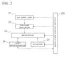
FIG. 2 is a block diagram showing the configuration of the stage device, on which a sample is mounted, in the exposure system. The stage device basically includes agas supply unit 21, apressure regulator 22, awafer stage 23,laser interferometers 24, theactuator 25, and the waferstage control section 208. - The
gas supply unit 21 generates and sends out clean dry air (CDA). - The
pressure regulator 22 is provided at a certain position in a gas flow path to connect thegas supply unit 21 and a supply port of an air bearing of thewafer stage 23, and adjusts the pressure of gas to be supplied to the air bearing. Thepressure regulator 22 is configured to include an electro-pneumatic regulator which adjusts the pressure of gas and ejects the gas at a set pressure. - The
laser interferometers 24 are disposed at positions facing a side surface of thewafer stage 23 and a side surface thereof perpendicular to the foregoing side surface, and measure the position of thewafer stage 23 and the attitude (pitching, rolling, and yawing) of thewafer stage 23 in two perpendicular directions. Alaser interferometer 24 is also provided above thewafer stage 23 to be used in measuring the vertical position of thewafer stage 23. - The wafer
stage control section 208 controls thegas supply unit 21, thepressure regulator 22, and thelaser interferometer 24 to detect the position of thewafer stage 23 with high accuracy. In particular, in the present invention, as described later, various kinds of control are performed by adjusting the pressure of air supplied to the air bearing of thewafer stage 23 so that particles present on thewafer stage 23 may be removed. -
FIGS. 3(a) to 3(c) are schematic diagrams showing the configuration of a principal part of a stage, which uses an air bearing, of a sample stage device. - The sample stage includes a slider (movable stage) 35 and a square shank (fixed stage) 34 which are disposed in a
vacuum sample chamber 37. Themovable stage 35 is configured in the form of a frame to surround the fixedstage 34, and moves along the fixedstage 34. The fixedstage 34 is disposed on astone surface plate 32 placed on vibration isolation mounts 31, withsupport rods 33 interposed therebetween. -
FIG. 3(c) shows an enlarged view of themovable stage 35. Themovable stage 35 basically includesair pads 36 and adifferential pumping portion 38. Theair pads 36 are used to emit to the fixedstage 34 air sent from thegas supply unit 21 through piping 39. Thedifferential pumping portion 38 adjusts the pressure of the emitted air so that the emitted air may not flow outside a gap portion between themovable stage 35 and the fixedstage 34. - The
air pads 36 are made of, for example, an aluminum ceramic or a zirconia ceramic, and have openings which determine the distribution of air. - The pressure of air supplied to the
air pads 36 is, for example, 0.5 [MPa]. By emitting the air toward the fixedstage 34, themovable stage 35 is floated. - The
differential pumping portion 38 hasexhaust channels exhaust channels exhaust channels -
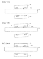
FIGS. 4(a) to 4(c) are views for explaining a stage cleaning process which is performed in the case where a particle is present on the track of themovable stage 35. - It is assumed that a
particle 41 is present on the fixedstage 34 as shown inFIG. 4(a) . This particle appears when themovable stage 35 is floated from the fixedstage 34, or is a particle or the like fallen on the fixedstage 34 after adhering to equipment constituting the sample chamber or equipment in a lens barrel. - The width of the gap between the
movable stage 35 and the fixedstage 34 is approximately 10 to 5 [µm] during normal stage in use. In the case where the height of a particle is smaller than the width for normal stage in use, no problem occurs during stage in use. However, in the case where the height of a particle is approximately equal to the gap width for stage in use, the particle may be entangled during movement. This may cause bumpy motion during movement or halt movement. - For this reason, the gap between the
movable stage 35 and the fixedstage 34 is set to have a width smaller than that for normal use to eliminate particles of such sizes from the track of themovable stage 35. Under this setting, particles are eliminated by moving themovable stage 35. -
FIG. 4(a) shows a state in which the width of the gap between the fixedstage 34 and themovable stage 35 is reduced with themovable stage 35 moved to one end (stroke end) of the fixedstage 34. For normal exposure, the floating height is set to approximately 5 [µm]. On the other hand, for cleaning, the floating height is set to, for example, 1 [µm]. Along with this, the width of the gap between the fixedstage 34 and a lower portion of themovable stage 35 becomes greater than that in normal use. -
FIG. 4(b) shows a state in which themovable stage 35 is moved to the other end of the fixedstage 34 with the state of air inFIG. 4(a) maintained. As shown inFIG. 4(b) , theparticle 41 is pushed and moved to an end portion of the fixedstage 34 by the movement of themovable stage 35. In such movement, themovable stage 34 may be reciprocated once or multiple times. - After that, as shown in
FIG. 4(c) , themovable stage 34 is moved to a sample stage use position (e.g., a central position of the fixed stage 34), and the width of the gap between the fixedstage 34 and themovable stage 35 is adjusted to a normal width. - Incidentally, though the above description has been made on the assumption that the
movable stage 35 is moved in only one direction, it is a matter of course that the present invention can be applied to movement in both X- and Y-directions as in an XY stage. -
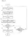
FIG. 5 is a flowchart showing one example of a stage cleaning process. - First, in step S11, the slider (movable stage) 35 is moved to a stroke end at one end of the range of stage movement.
- Then, in step S12, the floating height of the
slider 35 is adjusted to be lower than the floating height of theslider 35 for normal exposure. This adjustment is performed by reducing the pressure of air supplied to theair pads 36. By reducing the pressure of air, the width of the gap between a lower surface of theslider 35 and an upper surface of the square shank (fixed stage) 34 is adjusted to, for example, 2 [µm]. - Subsequently, in step S13, the
slider 35 is moved within the entire range of stage movement. Theslider 35 located at one end of the range of stage movement is moved to the other end stroke and then moved to the original end of the range of stage movement again. This causes particles which exist on the track of the air bearing and have heights of more than 2 [µm] to be pushed by a side portion of theslider 35 and moved to the vicinity of thesquare shank 34. - Next, in step S14, the
slider 35 is moved to a basic position (center of the range of stage movement). - After that, in step S15, the floating height of the
slider 35 is adjusted to a height for normal use by controlling thepressure regulator 22. - By the above-described stage cleaning process, particles present below the
slider 35 are removed. This stage cleaning process may be periodically executed. When exposure is carried out after this process, errors based on stage position are eliminated. Thus, it becomes possible to perform exposure with high position accuracy. - As described above, in the stage device and stage cleaning method of this embodiment, air supplied to the air bearing is regulated so that the width of the gap between the
movable stage 35 and the fixedstage 34 may become smaller than that for normal use, and themovable stage 35 is moved within the entire range of the track thereof. - This makes it possible to remove particles present on the track of the
movable stage 35 and larger than the gap width for normal use. - A stage device and stage cleaning method according to a second embodiment has a function of detecting whether or not there is a particle below the
slider 35. If it is determined that there is a particle, stage cleaning is executed. -
FIGS. 6(a) to 6(c) show an example of the case where there is a particle below themovable stage 35.FIGS. 6(a) to 6(c) show a state in which themovable stage 35 is at a height less than a normal floating height at a predetermined position (central region).FIG. 6(a) shows the case where aparticle 51 is present at an end portion on the fixedstage 34 and not present under themovable stage 35. In this case, the pitching and rolling of themovable stage 35 do not occur. -
FIG. 6(b) shows an example in which there is a particle under themovable stage 35. In the case where aparticle 51 is present under themovable stage 35 as shown inFIG. 6(b) , themovable stage 35 turns in the direction of movement and is inclined due to pitching. Thus, themovable stage 35 does not maintain its horizontal state anymore -
FIG. 6(c) shows an example in which there is a particle under themovable stage 35. Themovable stage 35 turns in a direction perpendicular to the direction of movement and is inclined due to rolling. Thus, themovable stage 35 does not maintain its horizontal state anymore. - The above-described pitching and rolling are measured by the
laser interferometers 24 provided at positions facing side surfaces of themovable stage 35. Thelaser interferometer 24 facing a side surface parallel to the direction of movement detects the state of pitching of themovable stage 35, and thelaser interferometer 24 facing a side surface parallel to a direction perpendicular to the direction of movement detects the state of rolling of themovable stage 35. -
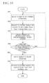
FIG. 7 is a flowchart showing one example of a stage cleaning process. - First, in step S21, the
slider 35 is moved to predetermined positions. The predetermined positions are, for example, three positions capable of covering the entire range of movement of theslider 35. Theslider 35 is moved to one of these three positions. - Then, in step S22, the floating height of the
slider 35 is adjusted to be lower than that for normal use. - Subsequently, in step S23, the rolling and pitching of the
stage 35 are measured. The rolling and pitching are measured by thelaser interferometers 24. - Next, in step S24, a determination is made as to whether or not the rolling or the pitching is in an allowable range. If the rolling or the pitching is not in the range of predetermined allowable values, it is determined that there is a particle under the
slider 35. Then, in step S25, a stage cleaning process for removing a particle is executed. As described in the first embodiment, this stage cleaning process is performed by moving theslider 35 throughout the entire range of stage movement. - On the other hand, if the rolling or the pitching is in the range of the predetermined values, a particle, if present, does not adversely affect movement based on the air bearing. Accordingly, it is determined that there is no particle at that position of the
slider 35, and the process goes to step S26. - Then, in step S26, a determination is made as to whether or not the rolling and pitching of the stage have been measured for all the predetermined positions. If the rolling and pitching of the stage have not been measured for all the predetermined positions, the process returns to step S21 to be continued for other position. If the rolling and pitching of the stage have been measured for all the predetermined positions, no stage cleaning is needed, and this particle detection process is terminated.
- Incidentally, the vertical position of the stage, instead of the rolling and pitching of the stage, may be detected to determine whether or not there is a particle.
-
FIG. 8 is a flowchart showing one example of a particle detection process which is performed in the case where the vertical position is determined. - First, in step S31, the
slider 35 is moved to predetermined positions. The predetermined positions are, for example, three positions capable of covering the entire range of movement of theslider 35. Theslider 35 is moved to one of these three positions. - Then, in step S32, the floating height of the
slider 35 is adjusted to be lower than that for normal use. - Subsequently, in step S33, the vertical position of the stage (slider 35) is measured. The vertical position of the stage is measured by, for example, the
laser interferometer 24 disposed above theslider 35. - Next, in step S34, a calculation is made of the amount of change in the vertical height of the
slider 35 with respect to the floating height of theslider 35. A calculation is made of the difference between the vertical position of theslider 35 for normal use and the vertical position of theslider 35 in the case of the lowered floating height. - Then, in step S35, a determination is made as to whether or not the amount of change is in an allowable range. For example, in the case where the floating height is set to a height which is d [µm] lower than that for normal use, if the amount of change in the vertical position of the
slider 35 is also d [µm], it is determined that theslider 35 is correctly lowered. On the other hand, if the amount of change is smaller than d [µm], it is determined that there is some obstacle in the gap between theslider 35 and the fixedstage 34. If the amount of change is not in the range of predetermined allowable values, it is determined that there is a particle under theslider 35. Then, in step S36, a stage cleaning process for removing a particle is executed. As described in the first embodiment, this stage cleaning process is performed by moving theslider 35 throughout the entire range of stage movement. - On the other hand, if the amount of change in the vertical position of the
slider 35 is in the range of the predetermined values, a particle, if present, does not adversely affect movement based on the air bearing. Accordingly, it is determined that there is no particle at that position of theslider 35, and the process goes to step S37. - Then, in step S37, a determination is made as to whether or not the vertical position of the stage has been measured for all the predetermined positions. If the vertical position of the stage has not been measured for all the predetermined positions, the process returns to step S31 to be continued for other position. If the vertical position of the stage has been measured for all the predetermined positions, no stage cleaning is needed, and this particle detection process is terminated.
- As described above, in the stage device and stage cleaning method of this embodiment, the pitching and rolling of the
movable stage 35 or a change in the vertical position of themovable stage 35 is detected at predetermined positions with the width of the gap between themovable stage 35 and the fixedstage 34 being narrowed by regulating air supplied to the air bearing. When the pitching or rolling of themovable stage 35 is detected, or when a change in the vertical position of themovable stage 35 is detected, stage cleaning is performed. - As a result, stage cleaning only needs to be carried out when necessary, and efficient stage cleaning can be performed.
- A third embodiment provides a technique adapted to the case where there is a particle which has adhered to the stage so firmly and thus is unremovable by the process of the first embodiment.
-
FIGS. 9(a) to 9(c) are views for explaining a stage cleaning process which is performed in the case where a particle is present under themovable stage 35. - In the case where a particle which has adhered to the fixed
stage 34, the particle may be incapable of being completely removed by a method such as described for the first embodiment in which a particle is pushed out to an end portion by themovable stage 35, thus remaining on the track. In this case, when the remaining particle is left as it is, the remaining particle may be overlaid with another particle. This may cause a problem during normal use. - To cope with this, at a position where there is such an adhering particle, the particle is eliminated by making the particle small.
-
FIG. 9(b) shows a state in which themovable stage 35 is twice or more reciprocated back and forth in the direction of movement with a short stroke, e.g., a stroke of 10 µm while the condition of air inFIG. 9(a) is maintained. By reciprocating themovable stage 35 twice or more, a particle 61a is crushed to be as small asparticles movable stage 35 becomes horizontal as shown inFIG. 9(c) . - Whether or not the
movable stage 35 becomes horizontal is determined by detecting the attitude of themovable stage 35 using thelaser interferometer 24 and making sure that pitching and rolling do not occur. -
FIG. 10 is a flowchart showing another example of a stage cleaning process. First, in step S41, theslider 35 is moved to a predetermined position. - Then, in step S42, the floating height of the
slider 35 is adjusted to be lower than that for normal use. - Subsequently, in step S43, the slider is reciprocated with a predetermined short stroke twice or more.
- Next, in step S44, a determination is made as to whether or not processing has been finished for all predetermined positions. If processing has been finished for all the predetermined positions, the process goes to step S45. If processing has not been finished for all the predetermined positions, the process goes to step S41 to be continued.
- Then, in step S45, the
slider 35 is moved to a basic position. - Subsequently, in step S46, the floating height of the
slider 35 is adjusted to be a height for normal use, and this stage cleaning process is terminated. - Incidentally, the stage cleaning process described for the third embodiment may be performed after the particle detection described for the second embodiment. In this case, the stage cleaning process shown in
FIG. 10 is executed in the "execution of stage cleaning" in step S25 ofFIG. 7 or step S36 ofFIG. 8 . - As described above, in the stage device and stage cleaning method of this embodiment, the
movable stage 35 is reciprocated twice or more within a short distance at a position where there is a particle. - This makes it possible to crush a particle adhering to the fixed
stage 34 or themovable stage 35 and to remove a particle present on the track of the air bearing. - In a fourth embodiment, a particle present on the fixed
stage 34 is removed using air for use in the air bearing. -
FIG. 11(a) shows a state in which there is aparticle 71 under themovable stage 35. Air supplied to the air bearing is used to remove such a particle from the track of themovable stage 35. - The
differential pumping portion 38 is a mechanism for gradually reducing the pressure of air emitted from theair pads 36 so that the air may not flow outside the gap portion between themovable stage 35 and the fixedstage 34. In this embodiment, the pressure placed on thedifferential pumping portion 38 is adjusted to a high pressure to cause the air to flow outside. For example, air is sucked throughexhaust channels FIG. 11(b) , and the pressure at thedifferential pumping portion 38 is increased to be higher than that for normal use by reducing the suction force. - Thus, particles present in the vicinities of both ends of the
movable stage 35 are blown away from the gap to the outside. In this state, by moving themovable stage 35 from one end to the other end, particles present on the track are pushed out and moved to end portions of the fixedstage 34. - Incidentally, in this case, since air in a last stage is emitted, the pressure in a vacuum chamber is increased. Accordingly, it is necessary to isolate an electron gun, which is an electron beam source, in terms of vacuum. Further, since the suction force of each exhaust channel is reduced to increase the pressure of differential pumping to a pressure higher than that for normal use, particles may flow back from the piping 73 connected to the exhaust channels. Accordingly, it is desirable that a filter for particle back-flow prevention be provided in the piping 73 of the differential pumping portion at a position near the gap portion.
-
FIG. 12 is a flowchart showing another example of a stage cleaning process. - First, in step S51, the
slider 35 is moved to a stroke end at one end of the range of stage movement. - Then, in step S52, the floating height of the
slider 35 is adjusted to that for normal use. In this adjustment, the floating height is adjusted to, for example, 5 [µm] by setting the pressure of air supplied to theair pads 36 to a pressure for normal use. - Subsequently, in step S53, the pressure in the
differential pumping portion 38 is increased to be higher than that for normal use. In normal use, the pressure of air is gradually reduced from atmospheric pressure to 10-4 [Pa] by thedifferential pumping portion 38 to prevent the air from flowing out. On the other hand, the suction forces of theexhaust channels 72a to 72c are adjusted to allow the air to have such a pressure that the air flows to the outside. - Next, in step S54, the
slider 35 is moved throughout the entire range of stage movement. Theslider 35 located at one end of the range of stage movement is moved to the other end stroke and then moved to the original end of the range of stage movement again. Thus, particles present on the track of the air bearing are blown away by the air to be removed from the course. - Then, in step S55, the
slider 35 is moved to a basic position. - Subsequently, in step S56, the pressure in the
differential pumping portion 38 is adjusted to a pressure for normal use, and this stage cleaning process is terminated. - Incidentally, the stage cleaning process described for the fourth embodiment may be performed after the particle detection described for the second embodiment. In this case, the stage cleaning process shown in
FIG. 12 is executed in the "execution of stage cleaning" in step S25 ofFIG. 7 or step S36 ofFIG. 8 . - As described above, in the stage device and stage cleaning method of this embodiment, stage cleaning is performed by moving the
movable stage 35 throughout the entire range of the track thereof with the width of the gap between themovable stage 35 and the fixedstage 34 being set to a width for normal use and with the pressure on thedifferential pumping portion 38 of the air bearing being increased. - This makes it possible to remove particles present on the track of the
movable stage 35.
Claims (6)
- A stage cleaning method for a stage device for use in a vacuum,
the stage device comprising:a fixed stage (34);a frame-shaped movable stage (35) surrounding and moving along the fixed stage (34), and having a sample mounting surface;a gas supply unit (21) arranged to generate gas;an air bearing arranged to float the movable stage (35) by supplying the gas to a gap portion between the fixed stage (34) and the movable stage (35); anda differential pumping portion (38) arranged to discharge the gas supplied to the
gap portion,the method comprising the steps of:in a cleaning mode of the stage device, regulating a floating height of the movable stage (35) and a pressure in the differential pumping portion (38); andmoving the movable stage (35) within a predetermined range while maintaining the floating height of the movable stage (35) and the pressure in the differential pumping portion (38). - The stage cleaning method according to claim 1
wherein
the step of regulating the floating height and the pressure in the differential pumping portion (38) comprises the steps of:adjusting the pressure in the differential pumping portion (38) to a pressure equal to that for the movable stage (35) in a normal use mode of the stage device when the floating height is set lower than that for the movable stage (35) in the normal use mode; oradjusting the pressure in the differential pumping portion (38) to a pressure higher than that for the movable stage (35) in the normal use mode when the floating height is set equal to that for the movable stage (35) in the normal use mode. - The stage cleaning method according to claim 1 , further comprising, before
the step of adjusting the floating height and the pressure in the differential pumping portion (35), the steps of:moving the movable stage (35) to a predetermined position;setting the floating height of the movable stage (35) lower than that for the movable stage (35) in the normal use mode and measuring rolling and pitching of the movable stage (35); anddetermining that a particle exists on a track of the air bearing if any of the rolling and pitching exceeds a predetermined allowable value. - The stage cleaning method according to claim 1 , further comprising, before
the step of regulating the floating height and the pressure in the differential pumping portion (38), the steps of:moving the movable stage (35) to a predetermined position;setting the floating height of the movable stage (35) lower than that for the movable stage (35) in the normal use mode and measuring a vertical position of the movable stage (35); anddetermining that a particle exists on a track of the air bearing if a change in the vertical position with respect to a change in a pressure for supplying the gas is out of a predetermined allowable value range. - The stage cleaning method according to any one of claims 3 and 4, wherein
the step of moving the movable stage (35) within the predetermined range comprises the steps of:moving the movable stage (35) to one end of the fixed stage; andmoving the movable stage (35) to an opposite end of the fixed stage (34). - The stage cleaning method according to any one of claims 3 and 4, wherein
the step of moving the movable stage (35) within the predetermined range is the step of reciprocating the movable stage (35) with a short stroke of 10 µm or less around a predetermined position twice or more.
Applications Claiming Priority (1)
| Application Number | Priority Date | Filing Date | Title |
|---|---|---|---|
| PCT/JP2009/055630 WO2010109574A1 (en) | 2009-03-23 | 2009-03-23 | Stage device and method for cleaning stage |
Publications (3)
| Publication Number | Publication Date |
|---|---|
| EP2249378A1 EP2249378A1 (en) | 2010-11-10 |
| EP2249378A4 EP2249378A4 (en) | 2011-02-23 |
| EP2249378B1 true EP2249378B1 (en) | 2015-09-30 |
Family
ID=42736422
Family Applications (1)
| Application Number | Title | Priority Date | Filing Date |
|---|---|---|---|
| EP09821404.2A Active EP2249378B1 (en) | 2009-03-23 | 2009-03-23 | Method for cleaning stage |
Country Status (4)
| Country | Link |
|---|---|
| US (2) | US8281794B2 (en) |
| EP (1) | EP2249378B1 (en) |
| JP (1) | JP5166510B2 (en) |
| WO (1) | WO2010109574A1 (en) |
Families Citing this family (5)
| Publication number | Priority date | Publication date | Assignee | Title |
|---|---|---|---|---|
| EP2947679A4 (en) * | 2012-11-20 | 2017-02-08 | Nikon Corporation | Exposure device, mobile device, and device manufacturing method |
| US9740113B2 (en) | 2014-07-02 | 2017-08-22 | Asml Netherlands B.V. | Lithographic apparatus, device manufacturing method and method of clamping an object |
| JP2018092994A (en) * | 2016-11-30 | 2018-06-14 | キヤノン株式会社 | Stage device, detection method, and method of manufacturing article |
| JP7191764B2 (en) * | 2019-05-08 | 2022-12-19 | 日本電子株式会社 | Gas floating transfer device and cleaning method |
| JP2021184423A (en) * | 2020-05-21 | 2021-12-02 | キヤノン株式会社 | Processing apparatus, measuring method, and article manufacturing method |
Citations (2)
| Publication number | Priority date | Publication date | Assignee | Title |
|---|---|---|---|---|
| US4956024A (en) * | 1988-01-11 | 1990-09-11 | The Perkin Elmer Corporation | Non-contacting method of cleaning surfaces with a planoar gas bearing |
| US6565419B1 (en) * | 1999-02-05 | 2003-05-20 | Advantest Corporation | Method of removing particles from stage and cleaning plate |
Family Cites Families (9)
| Publication number | Priority date | Publication date | Assignee | Title |
|---|---|---|---|---|
| JP2001153140A (en) * | 1999-11-26 | 2001-06-08 | Fujitsu Ltd | Gas bearing |
| JP2002349568A (en) | 2001-05-23 | 2002-12-04 | Mitsutoyo Corp | Exhaust/recovery type air bearing |
| JP2002349569A (en) * | 2001-05-25 | 2002-12-04 | Canon Inc | Static pressure bearing device and stage device using it |
| JP2002359170A (en) | 2001-05-30 | 2002-12-13 | Nikon Corp | Stage apparatus and aligner |
| JP2004319902A (en) | 2003-04-18 | 2004-11-11 | Advantest Corp | Stage device and exposure device |
| JP2006066589A (en) | 2004-08-26 | 2006-03-09 | Nikon Corp | Stage device and exposure equipment, device-manufacturing method and method of driving stage device |
| WO2007016688A1 (en) | 2005-08-02 | 2007-02-08 | New Way Machine Components, Inc. | A method and a device for depositing a film of material or otherwise processing or inspecting, a substrate as it passes through a vacuum environment guided by a plurality of opposing and balanced air bearing lands and sealed by differentially pumped groves and sealing lands in a non-contact manner |
| WO2007069713A1 (en) * | 2005-12-15 | 2007-06-21 | Kyocera Corporation | Hydrostatic slider |
| US20100092113A1 (en) * | 2006-03-22 | 2010-04-15 | Kyocera Corporation | Static pressure slider and transferring device and processing device provided with the same |
-
2009
- 2009-03-23 WO PCT/JP2009/055630 patent/WO2010109574A1/en active Application Filing
- 2009-03-23 JP JP2010500586A patent/JP5166510B2/en active Active
- 2009-03-23 EP EP09821404.2A patent/EP2249378B1/en active Active
-
2010
- 2010-04-29 US US12/799,675 patent/US8281794B2/en active Active
-
2011
- 2011-12-29 US US13/340,251 patent/US8382911B2/en active Active
Patent Citations (2)
| Publication number | Priority date | Publication date | Assignee | Title |
|---|---|---|---|---|
| US4956024A (en) * | 1988-01-11 | 1990-09-11 | The Perkin Elmer Corporation | Non-contacting method of cleaning surfaces with a planoar gas bearing |
| US6565419B1 (en) * | 1999-02-05 | 2003-05-20 | Advantest Corporation | Method of removing particles from stage and cleaning plate |
Also Published As
| Publication number | Publication date |
|---|---|
| US8382911B2 (en) | 2013-02-26 |
| US8281794B2 (en) | 2012-10-09 |
| EP2249378A4 (en) | 2011-02-23 |
| US20100236576A1 (en) | 2010-09-23 |
| EP2249378A1 (en) | 2010-11-10 |
| WO2010109574A1 (en) | 2010-09-30 |
| US20120118325A1 (en) | 2012-05-17 |
| JPWO2010109574A1 (en) | 2012-09-20 |
| JP5166510B2 (en) | 2013-03-21 |
Similar Documents
| Publication | Publication Date | Title |
|---|---|---|
| EP2249378B1 (en) | Method for cleaning stage | |
| US8530857B2 (en) | Stage device | |
| WO2007086400A1 (en) | Method and apparatus for inspecting sample surface | |
| JP6367430B2 (en) | Assembly and method for vertically lifting a module of a lithography system and a lithography system having such an assembly | |
| JP2002329659A (en) | Charged particle beam exposure method, charged particle beam aligner and device manufacturing method | |
| US7960703B2 (en) | Charged-particle beam lithography apparatus and device manufacturing method | |
| US20220084781A1 (en) | Stage anti-fretting mechanism for roller bearing lifetime improvement | |
| JP4571558B2 (en) | Method for adjusting charged particle beam exposure apparatus and charged particle beam exposure apparatus | |
| JP2010123354A (en) | Charged particle beam device | |
| JP4927506B2 (en) | Charged particle beam device and imaging method of charged particle beam device | |
| US7049611B2 (en) | Charged-particle beam lithographic system | |
| JP5155209B2 (en) | Stage equipment | |
| JP2010219373A (en) | Lithography apparatus | |
| US11352694B2 (en) | Drawing apparatus and control method thereof | |
| JP2019009204A (en) | Stage device, lithographic device, and article manufacturing method | |
| JP2005032480A (en) | Charged particle beam exposure apparatus, and device manufacturing method using the same | |
| US20030044697A1 (en) | Methods and apparatus for correcting the proximity effect in a charged-particle-beam microlithography system and devices manufactured from the same | |
| KR20200123000A (en) | Stage apparatus, lithography apparatus, and method of manufacturing article | |
| JP2005032838A (en) | Method and device for charged particle beam lithography and method of manufacturing device | |
| JP2002015976A (en) | Proximity effect correcting method and device- manufacturing method | |
| JP2006114726A (en) | Charged-particle-beam exposure apparatus | |
| JP2012038858A (en) | Conditioning method for electron gun and electron beam lithography system | |
| JP2007005556A (en) | Charged-particle beam exposure device | |
| DE102015212656A1 (en) | Projection exposure apparatus for semiconductor lithography with fluid storage |
Legal Events
| Date | Code | Title | Description |
|---|---|---|---|
| PUAI | Public reference made under article 153(3) epc to a published international application that has entered the european phase |
Free format text: ORIGINAL CODE: 0009012 |
|
| 17P | Request for examination filed |
Effective date: 20100422 |
|
| AK | Designated contracting states |
Kind code of ref document: A1 Designated state(s): AT BE BG CH CY CZ DE DK EE ES FI FR GB GR HR HU IE IS IT LI LT LU LV MC MK MT NL NO PL PT RO SE SI SK TR |
|
| R17P | Request for examination filed (corrected) |
Effective date: 20100422 |
|
| R17P | Request for examination filed (corrected) |
Effective date: 20100422 |
|
| A4 | Supplementary search report drawn up and despatched |
Effective date: 20110125 |
|
| RIC1 | Information provided on ipc code assigned before grant |
Ipc: G03F 7/20 20060101ALI20110119BHEP Ipc: H01L 21/00 20060101ALI20110119BHEP Ipc: H01L 21/027 20060101AFI20100824BHEP Ipc: H01J 37/317 20060101ALI20110119BHEP |
|
| DAX | Request for extension of the european patent (deleted) | ||
| 17Q | First examination report despatched |
Effective date: 20130328 |
|
| GRAP | Despatch of communication of intention to grant a patent |
Free format text: ORIGINAL CODE: EPIDOSNIGR1 |
|
| RIC1 | Information provided on ipc code assigned before grant |
Ipc: H01L 21/027 20060101AFI20150617BHEP Ipc: H01J 37/317 20060101ALI20150617BHEP Ipc: H01L 21/00 20060101ALI20150617BHEP Ipc: G03F 7/20 20060101ALI20150617BHEP |
|
| INTG | Intention to grant announced |
Effective date: 20150629 |
|
| GRAS | Grant fee paid |
Free format text: ORIGINAL CODE: EPIDOSNIGR3 |
|
| GRAA | (expected) grant |
Free format text: ORIGINAL CODE: 0009210 |
|
| AK | Designated contracting states |
Kind code of ref document: B1 Designated state(s): AT BE BG CH CY CZ DE DK EE ES FI FR GB GR HR HU IE IS IT LI LT LU LV MC MK MT NL NO PL PT RO SE SI SK TR |
|
| REG | Reference to a national code |
Ref country code: CH Ref legal event code: EP Ref country code: GB Ref legal event code: FG4D |
|
| REG | Reference to a national code |
Ref country code: AT Ref legal event code: REF Ref document number: 752866 Country of ref document: AT Kind code of ref document: T Effective date: 20151015 |
|
| REG | Reference to a national code |
Ref country code: IE Ref legal event code: FG4D |
|
| REG | Reference to a national code |
Ref country code: DE Ref legal event code: R096 Ref document number: 602009034150 Country of ref document: DE |
|
| PG25 | Lapsed in a contracting state [announced via postgrant information from national office to epo] |
Ref country code: FI Free format text: LAPSE BECAUSE OF FAILURE TO SUBMIT A TRANSLATION OF THE DESCRIPTION OR TO PAY THE FEE WITHIN THE PRESCRIBED TIME-LIMIT Effective date: 20150930 Ref country code: LV Free format text: LAPSE BECAUSE OF FAILURE TO SUBMIT A TRANSLATION OF THE DESCRIPTION OR TO PAY THE FEE WITHIN THE PRESCRIBED TIME-LIMIT Effective date: 20150930 Ref country code: GR Free format text: LAPSE BECAUSE OF FAILURE TO SUBMIT A TRANSLATION OF THE DESCRIPTION OR TO PAY THE FEE WITHIN THE PRESCRIBED TIME-LIMIT Effective date: 20151231 Ref country code: LT Free format text: LAPSE BECAUSE OF FAILURE TO SUBMIT A TRANSLATION OF THE DESCRIPTION OR TO PAY THE FEE WITHIN THE PRESCRIBED TIME-LIMIT Effective date: 20150930 Ref country code: NO Free format text: LAPSE BECAUSE OF FAILURE TO SUBMIT A TRANSLATION OF THE DESCRIPTION OR TO PAY THE FEE WITHIN THE PRESCRIBED TIME-LIMIT Effective date: 20151230 |
|
| REG | Reference to a national code |
Ref country code: NL Ref legal event code: MP Effective date: 20150930 |
|
| REG | Reference to a national code |
Ref country code: LT Ref legal event code: MG4D |
|
| REG | Reference to a national code |
Ref country code: AT Ref legal event code: MK05 Ref document number: 752866 Country of ref document: AT Kind code of ref document: T Effective date: 20150930 |
|
| PG25 | Lapsed in a contracting state [announced via postgrant information from national office to epo] |
Ref country code: SE Free format text: LAPSE BECAUSE OF FAILURE TO SUBMIT A TRANSLATION OF THE DESCRIPTION OR TO PAY THE FEE WITHIN THE PRESCRIBED TIME-LIMIT Effective date: 20150930 Ref country code: HR Free format text: LAPSE BECAUSE OF FAILURE TO SUBMIT A TRANSLATION OF THE DESCRIPTION OR TO PAY THE FEE WITHIN THE PRESCRIBED TIME-LIMIT Effective date: 20150930 |
|
| PG25 | Lapsed in a contracting state [announced via postgrant information from national office to epo] |
Ref country code: IS Free format text: LAPSE BECAUSE OF FAILURE TO SUBMIT A TRANSLATION OF THE DESCRIPTION OR TO PAY THE FEE WITHIN THE PRESCRIBED TIME-LIMIT Effective date: 20160130 Ref country code: NL Free format text: LAPSE BECAUSE OF FAILURE TO SUBMIT A TRANSLATION OF THE DESCRIPTION OR TO PAY THE FEE WITHIN THE PRESCRIBED TIME-LIMIT Effective date: 20150930 Ref country code: IT Free format text: LAPSE BECAUSE OF FAILURE TO SUBMIT A TRANSLATION OF THE DESCRIPTION OR TO PAY THE FEE WITHIN THE PRESCRIBED TIME-LIMIT Effective date: 20150930 Ref country code: SK Free format text: LAPSE BECAUSE OF FAILURE TO SUBMIT A TRANSLATION OF THE DESCRIPTION OR TO PAY THE FEE WITHIN THE PRESCRIBED TIME-LIMIT Effective date: 20150930 Ref country code: CZ Free format text: LAPSE BECAUSE OF FAILURE TO SUBMIT A TRANSLATION OF THE DESCRIPTION OR TO PAY THE FEE WITHIN THE PRESCRIBED TIME-LIMIT Effective date: 20150930 Ref country code: ES Free format text: LAPSE BECAUSE OF FAILURE TO SUBMIT A TRANSLATION OF THE DESCRIPTION OR TO PAY THE FEE WITHIN THE PRESCRIBED TIME-LIMIT Effective date: 20150930 Ref country code: EE Free format text: LAPSE BECAUSE OF FAILURE TO SUBMIT A TRANSLATION OF THE DESCRIPTION OR TO PAY THE FEE WITHIN THE PRESCRIBED TIME-LIMIT Effective date: 20150930 |
|
| PG25 | Lapsed in a contracting state [announced via postgrant information from national office to epo] |
Ref country code: AT Free format text: LAPSE BECAUSE OF FAILURE TO SUBMIT A TRANSLATION OF THE DESCRIPTION OR TO PAY THE FEE WITHIN THE PRESCRIBED TIME-LIMIT Effective date: 20150930 Ref country code: PL Free format text: LAPSE BECAUSE OF FAILURE TO SUBMIT A TRANSLATION OF THE DESCRIPTION OR TO PAY THE FEE WITHIN THE PRESCRIBED TIME-LIMIT Effective date: 20150930 Ref country code: PT Free format text: LAPSE BECAUSE OF FAILURE TO SUBMIT A TRANSLATION OF THE DESCRIPTION OR TO PAY THE FEE WITHIN THE PRESCRIBED TIME-LIMIT Effective date: 20160201 Ref country code: RO Free format text: LAPSE BECAUSE OF FAILURE TO SUBMIT A TRANSLATION OF THE DESCRIPTION OR TO PAY THE FEE WITHIN THE PRESCRIBED TIME-LIMIT Effective date: 20150930 |
|
| REG | Reference to a national code |
Ref country code: DE Ref legal event code: R097 Ref document number: 602009034150 Country of ref document: DE |
|
| PLBE | No opposition filed within time limit |
Free format text: ORIGINAL CODE: 0009261 |
|
| STAA | Information on the status of an ep patent application or granted ep patent |
Free format text: STATUS: NO OPPOSITION FILED WITHIN TIME LIMIT |
|
| PG25 | Lapsed in a contracting state [announced via postgrant information from national office to epo] |
Ref country code: BE Free format text: LAPSE BECAUSE OF NON-PAYMENT OF DUE FEES Effective date: 20160331 Ref country code: DK Free format text: LAPSE BECAUSE OF FAILURE TO SUBMIT A TRANSLATION OF THE DESCRIPTION OR TO PAY THE FEE WITHIN THE PRESCRIBED TIME-LIMIT Effective date: 20150930 |
|
| 26N | No opposition filed |
Effective date: 20160701 |
|
| PG25 | Lapsed in a contracting state [announced via postgrant information from national office to epo] |
Ref country code: LU Free format text: LAPSE BECAUSE OF FAILURE TO SUBMIT A TRANSLATION OF THE DESCRIPTION OR TO PAY THE FEE WITHIN THE PRESCRIBED TIME-LIMIT Effective date: 20160323 Ref country code: MC Free format text: LAPSE BECAUSE OF FAILURE TO SUBMIT A TRANSLATION OF THE DESCRIPTION OR TO PAY THE FEE WITHIN THE PRESCRIBED TIME-LIMIT Effective date: 20150930 |
|
| REG | Reference to a national code |
Ref country code: CH Ref legal event code: PL |
|
| GBPC | Gb: european patent ceased through non-payment of renewal fee |
Effective date: 20160323 |
|
| PG25 | Lapsed in a contracting state [announced via postgrant information from national office to epo] |
Ref country code: SI Free format text: LAPSE BECAUSE OF FAILURE TO SUBMIT A TRANSLATION OF THE DESCRIPTION OR TO PAY THE FEE WITHIN THE PRESCRIBED TIME-LIMIT Effective date: 20150930 |
|
| REG | Reference to a national code |
Ref country code: IE Ref legal event code: MM4A |
|
| PG25 | Lapsed in a contracting state [announced via postgrant information from national office to epo] |
Ref country code: BE Free format text: LAPSE BECAUSE OF FAILURE TO SUBMIT A TRANSLATION OF THE DESCRIPTION OR TO PAY THE FEE WITHIN THE PRESCRIBED TIME-LIMIT Effective date: 20150930 |
|
| REG | Reference to a national code |
Ref country code: FR Ref legal event code: ST Effective date: 20161130 |
|
| PG25 | Lapsed in a contracting state [announced via postgrant information from national office to epo] |
Ref country code: LI Free format text: LAPSE BECAUSE OF NON-PAYMENT OF DUE FEES Effective date: 20160331 Ref country code: IE Free format text: LAPSE BECAUSE OF NON-PAYMENT OF DUE FEES Effective date: 20160323 Ref country code: GB Free format text: LAPSE BECAUSE OF NON-PAYMENT OF DUE FEES Effective date: 20160323 Ref country code: CH Free format text: LAPSE BECAUSE OF NON-PAYMENT OF DUE FEES Effective date: 20160331 Ref country code: FR Free format text: LAPSE BECAUSE OF NON-PAYMENT OF DUE FEES Effective date: 20160331 |
|
| PG25 | Lapsed in a contracting state [announced via postgrant information from national office to epo] |
Ref country code: MT Free format text: LAPSE BECAUSE OF FAILURE TO SUBMIT A TRANSLATION OF THE DESCRIPTION OR TO PAY THE FEE WITHIN THE PRESCRIBED TIME-LIMIT Effective date: 20150930 |
|
| PG25 | Lapsed in a contracting state [announced via postgrant information from national office to epo] |
Ref country code: CY Free format text: LAPSE BECAUSE OF FAILURE TO SUBMIT A TRANSLATION OF THE DESCRIPTION OR TO PAY THE FEE WITHIN THE PRESCRIBED TIME-LIMIT Effective date: 20150930 Ref country code: HU Free format text: LAPSE BECAUSE OF FAILURE TO SUBMIT A TRANSLATION OF THE DESCRIPTION OR TO PAY THE FEE WITHIN THE PRESCRIBED TIME-LIMIT; INVALID AB INITIO Effective date: 20090323 |
|
| PG25 | Lapsed in a contracting state [announced via postgrant information from national office to epo] |
Ref country code: MT Free format text: LAPSE BECAUSE OF FAILURE TO SUBMIT A TRANSLATION OF THE DESCRIPTION OR TO PAY THE FEE WITHIN THE PRESCRIBED TIME-LIMIT Effective date: 20160331 Ref country code: TR Free format text: LAPSE BECAUSE OF FAILURE TO SUBMIT A TRANSLATION OF THE DESCRIPTION OR TO PAY THE FEE WITHIN THE PRESCRIBED TIME-LIMIT Effective date: 20150930 Ref country code: MK Free format text: LAPSE BECAUSE OF FAILURE TO SUBMIT A TRANSLATION OF THE DESCRIPTION OR TO PAY THE FEE WITHIN THE PRESCRIBED TIME-LIMIT Effective date: 20150930 |
|
| PG25 | Lapsed in a contracting state [announced via postgrant information from national office to epo] |
Ref country code: BG Free format text: LAPSE BECAUSE OF FAILURE TO SUBMIT A TRANSLATION OF THE DESCRIPTION OR TO PAY THE FEE WITHIN THE PRESCRIBED TIME-LIMIT Effective date: 20150930 |
|
| P01 | Opt-out of the competence of the unified patent court (upc) registered |
Effective date: 20230529 |
|
| PGFP | Annual fee paid to national office [announced via postgrant information from national office to epo] |
Ref country code: DE Payment date: 20240206 Year of fee payment: 16 |