EP2245763B1 - Realizing fdd capability by leveraging existing tdd technology - Google Patents
Realizing fdd capability by leveraging existing tdd technology Download PDFInfo
- Publication number
- EP2245763B1 EP2245763B1 EP09700322.2A EP09700322A EP2245763B1 EP 2245763 B1 EP2245763 B1 EP 2245763B1 EP 09700322 A EP09700322 A EP 09700322A EP 2245763 B1 EP2245763 B1 EP 2245763B1
- Authority
- EP
- European Patent Office
- Prior art keywords
- frequency band
- tdd carrier
- transmission
- tdd
- transmission frame
- Prior art date
- Legal status (The legal status is an assumption and is not a legal conclusion. Google has not performed a legal analysis and makes no representation as to the accuracy of the status listed.)
- Not-in-force
Links
Images

Classifications
-
- H—ELECTRICITY
- H04—ELECTRIC COMMUNICATION TECHNIQUE
- H04B—TRANSMISSION
- H04B7/00—Radio transmission systems, i.e. using radiation field
- H04B7/24—Radio transmission systems, i.e. using radiation field for communication between two or more posts
- H04B7/26—Radio transmission systems, i.e. using radiation field for communication between two or more posts at least one of which is mobile
- H04B7/2615—Radio transmission systems, i.e. using radiation field for communication between two or more posts at least one of which is mobile using hybrid frequency-time division multiple access [FDMA-TDMA]
-
- H—ELECTRICITY
- H04—ELECTRIC COMMUNICATION TECHNIQUE
- H04L—TRANSMISSION OF DIGITAL INFORMATION, e.g. TELEGRAPHIC COMMUNICATION
- H04L5/00—Arrangements affording multiple use of the transmission path
- H04L5/14—Two-way operation using the same type of signal, i.e. duplex
-
- H—ELECTRICITY
- H04—ELECTRIC COMMUNICATION TECHNIQUE
- H04W—WIRELESS COMMUNICATION NETWORKS
- H04W72/00—Local resource management
- H04W72/50—Allocation or scheduling criteria for wireless resources
- H04W72/535—Allocation or scheduling criteria for wireless resources based on resource usage policies
-
- H—ELECTRICITY
- H04—ELECTRIC COMMUNICATION TECHNIQUE
- H04W—WIRELESS COMMUNICATION NETWORKS
- H04W84/00—Network topologies
- H04W84/02—Hierarchically pre-organised networks, e.g. paging networks, cellular networks, WLAN [Wireless Local Area Network] or WLL [Wireless Local Loop]
- H04W84/04—Large scale networks; Deep hierarchical networks
- H04W84/042—Public Land Mobile systems, e.g. cellular systems
Definitions
- US 2007/0058584 relates to an apparatus comprising a base station employing a duplexing technique that allows simultaneous transmission and reception on a plurality of frequencies such that in each transmit time interval downlink transmission is carried over a frequency band used for uplink reception in a contiguously preceding transmit time interval.
- WO 2005/088866 A1 discloses a method in which uplink and downlink frequencies are allocated in an orthogonal manner such that at one time instant a certain carrier frequency is used for uplink transmission and at some other time constant for downlink transmission.
- US 6,587,444 B1 describes a flexible channel architecture which supports full duplex, RF communication between a base station and the group of remote terminals.
- US 2007/0286156 relates to a wireless system and method which includes a frequency division duplex system configured to provide at least a first FDD channel operating within a first frequency band.
- a method and apparatus for using TDD transmission carriers, frame structure, ASICs, and software to define an FDD communication solution are provided.
- a cellular communication system comprises a base transmission station (BTS) that transmits information on a downlink (DL) frequency band to one or more mobile devices and receives information on an uplink (UL) frequency band from the one or more mobile devices, and a frequency division duplex (FDD) processor that alternately translates first and second time division duplexed (TDD) carriers to a transmission signal on the DL frequency band according to a predefined switching schedule.
- BTS base transmission station
- FDD frequency division duplex
- TDD time division duplexed
- the system further comprises a memory that stores information related to the predefined switching schedule, TDD carrier identity, and DL and UL frequency bands.
- the base station transmits the downlink transmissions on the DL frequency band using the translated first TDD carrier for a first portion of a transmission frame, and using the translated second TDD carrier for second portion of the transmission frame.
- the base station receives uplink transmissions on the UL frequency band with the second carrier being translated to the uplink frequency band for the first portion of the transmission frame, and sing the first TDD carrier beeing translated to the uplink frequency band for the second portion of the transmission frame.
- a method of using existing TDD communication structures to perform FDD communication comprises transmitting a DL signal on a DL frequency band with the translated a being translated to the downlink frequency band first TDD carrier during a first portion of a transmission frame, receiving a UL signal on a UL frequency band with the translated a second TDD carrier being translated to the uplink frequency band during the first portion of the transmission frame, and transmitting the DL signal on the DL frequency band with the translated second TDD carrier being translated to the downlink frequency band during a second portion of the transmission frame.
- the method further comprises receiving the UL signal on the UL frequency band with the first TDD carrier being translated to the uplink frequency band during the second portion of the transmission frame, and switching from the first TDD carrier to the second TDD carrier on the DL frequency band, and from the second TDD carrier to the first TDD carrier on the UL frequency band, during a first transition gap that occurs between the first and second portions of the transmission frame.
- An advantage of the various aspects described herein is that an FDD solution for frequency bands where TDD solutions are restrictive is created.
- Another advantage resides in enabling vendors to leverage and/or re-use the current frame structure, ASICs, and software of the TDD solution in implementing the FDD option.
- a further advantage resides in reducing cost for vendors and operators by leveraging the economies of scale of TDD solutions in implementing the FDD option.
- Yet another advantage resides in providing spectral efficiency close to a true FDD solution.
- Another advantage resides in reducing terminal cost relative to a full duplex FDD solution by utilizing half-duplex terminals that do not require a duplexer.
- Yet another advantage resides in leveraging the current TDD solution to provide a faster time-to-market FDD option than can be achieved using the 802.16e standards-defined FDD solution.
- This invention relates to a method and apparatus for leveraging existing TDD ASICs, software, and infrastructure to provide FDD communication capability by switching 802.16e-defined WiMAX TDD carriers between two transmission frequency bands mid-frame, thereby causing the TDD carriers to behave as half duplex FDD carriers.
- the invention is particularly directed to the art of cellular communication, and will be thus described with specific reference thereto, it will be appreciated that the invention may have usefulness in other fields and applications.
- the invention may be used in communication devices, gaming devices, or any other devices in which it is desirable to improve frequency reuse, reduce interference, etc.
- FIGURE 1 illustrates a system for providing frequency division duplexed (FDD) communication using a time division duplexed (TDD) architecture, in accordance with various aspects described herein.
- a worldwide interoperability for microwave access (WiMAX) FDD solution is defined that leverages existing WiMAX TDD solutions currently based on the currently defined WiMAX TDD profiles, which maximizes the reuse of the TDD WiMAX solution/ecosystem.
- WiMAX worldwide interoperability for microwave access
- the WiMAX FDD solution maintains the frame structure as the WAVE 1 & 2 WiMAX TDD profiles and effects a change at the radio frequency (RF) level to support transmission and reception in different frequency bands, thereby facilitating leveraging the ASICs and software designed and developed for the WAVE 1 & 2 WIMAX TDD solutions. Accordingly, a WiMAX FDD solution is described herein that is different from the 802.16e standards-defined FDD solution.
- the system illustrated in Figure 1 comprises a base transceiver station (BTS) 10 that includes one or more receivers 12 for receiving information on an uplink (UL), or reverse link, from one or more mobile devices (not shown).
- the receiver 12 is coupled to a demultiplexer/demodulator 14 that demultiplexes and/or demodulates received information signals from one or more mobile devices.
- a processor 16 receives the demultiplexed signal data, and is coupled to a machine-readable memory 18 that stores information related to signal processing and the like.
- the memory 18 stores algorithms for performing various functions associated with wireless and/or cellular communication, including but not limited to demultiplexing signals received on the uplink, processing information contained in the signals, generating and multiplexing signals for transmission on a downlink (DL), or forward link, and any other suitable communication protocols, as will be appreciated by those of skill.
- the processor 16 is coupled to a multiplexer 20 that multiplexes and/or modulates transmission signals generated or relayed by the processor 16 for transmission by one or more transmitters 22 on the downlink to one or more mobile devices (not shown).
- the receiver 12, demux 14, processor 16, memory 18, multiplexer 20, and transmitter(s) 22 are further coupled to an FDD processer 24 that executes instructions for performing FDD communication protocols using TDD infrastructure and software.
- the FDD processor 24 can use two TDD carriers in the same paired spectrum by off-setting the DL and UL transmissions in frequency (e.g., using two half-duplex FDD carriers) and by defining DL and UL transmission/reception periods such that only one of the TDD carriers transmits on the DL at any given instant in time (while the second TDD carrier transmits on the UL), as described below with regard to Figure 3 .
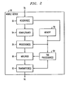
- FIGURE 2 illustrates a mobile device 50 that can be employed for FDD communication with the BTS 10.
- the mobile device 50 may be a cellular phone, a laptop, a smart phone, a wireless computing device, or some other suitable wireless communication device.
- the mobile device 50 comprises one or more receivers 52 for receiving information on the DL from one or more base stations ( Fig. 1 ).
- the receiver 52 is coupled to a demultiplexer/demodulator 54 that demultiplexes and/or demodulates received information signals from the base station(s).
- a processor 56 receives the demultiplexed signal data, and is coupled to a machine-readable memory 58 that stores information related to signal processing and the like.
- the memory 58 stores algorithms for performing various functions associated with wireless and/or cellular communication, including but not limited to demultiplexing signals received on the downlink, processing information contained in the signals, generating and multiplexing signals for transmission on the UL, and any other suitable communication protocols, as will be appreciated by those of skill.
- the processor 56 is coupled to a multiplexer 60 that multiplexes and/or modulates transmission signals generated or relayed by the processor 56 for transmission by one or more transmitters 62 on the DL to one or more base stations.
- the receiver 52, demux/demod 54, processor 56, memory 58, multiplexer 60, and transmitter(s) 62 are further coupled to an FDD processer 64 that executes instructions for performing FDD communication protocols using TDD infrastructure and software.
- the FDD processor 64 can use two TDD carriers in the same paired spectrum by off-setting DL and UL transmissions in frequency (e.g., using two half-duplex FDD carriers) and by defining DL and UL transmission/reception periods such that only one of the TDD carriers transmits on the DL at any given instant in time (while the second TDD carrier transmits on the UL), as described below with regard to Figure 3 .
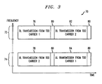
- FIGURE 3 is an illustration of a transmission/reception scheme 70, such as may be executed by the FDD processor, in accordance with various aspects described herein.
- the BTS and mobile terminals can behave as though they are employing a TDD communication protocol, with a modification to frequency translation for DL vs. UL transmission.
- the BTS utilizes the entire paired frequency bandwidth, which comprises two paired frequency bands 72, 74, thus achieving spectral efficiency similar to a true FDD system.
- the first frequency band 72 is dedicated to DL transmission
- the second transmission band 74 is dedicated to uplink transmission.
- the first frequency band 72 is approximately 1710 kHz to 1755 kHz
- the second frequency band 74 is approximately 2110 kHz to 2155 kHz.
- the paired spectrum of frequency bands 72, 74 is consistent with a global system for mobile (GSM) communication paired spectrum band, such as T-GSM 380 T-GSM 410, GSM 450, GSM 480, GSM 710, GSM 750, T-GSM 810, GSM 850, P-GSM 900, E-GSM 900, R-GSM 900, T-GSM 900, DCS 1800, PCS 1900, or the like.
- GSM global system for mobile
- the communication scheme 70 shows frequency as a function of time, wherein a first DL transmission period 76 permits DL transmission to occur using a first TDD carrier (TDD Carrier 1) over the first frequency band 72, while a first UL transmission period 78 permits UL transmission over the second frequency band 74 using a second TDD carrier (TDD Carrier 2).
- a transition period 80 is executed, wherein neither UL nor DL transmission occurs.
- the transition period has a duration of approximately 60 ⁇ s, although other durations are contemplated.
- the carriers are switched so that during a second DL transmission period 82, DL transmission occurs on the first frequency band 72 using the second TTD carrier, and UL transmission occurs over the second frequency band 74 using the first TDD carrier.
- the transition period is employed to ensure that UL and DL transmission does not occur concurrently on both frequency bands using the same TDD carrier, which facilitates the leveraging of the TDD solution.
- another transition period is employed while the respective DL and UL transmission carriers are switched again.
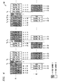
- FIGURE 4 illustrates an example an 802.16e-based WiMAX FDD transmission scheme 100 that uses two "802.16e WiMAX TDD carriers" with DL and UL transmissions translated to first and second frequency bands f1 and f2, respectively, which results in respective half-FDD (H-FDD) carriers.
- the two TDD carriers are illustrated as shaded (H-FDD Carrier 1) and unshaded (H-FDD Carrier 2) symbols over several transmission frames.
- a transmission frame in one example, comprises 47 symbols, each of which is approximately 100 ⁇ s long.
- the first and second TDD carriers can be distinguished from each other by using two different preambles, for example. Initially, a mobile device searches all preambles to find one that produces a high correlation (e.g., mobiles are programmed to search the preambles in different orders depending on a given mobile's configuration).
- the illustrated example demonstrates how one WiMAX H-FDD carrier using DL:UL symbol ratio of 29:18 can be combined with a second WiMAX H-FDD carrier using a 19:27 DL:UL symbol ratio.
- the figure also demonstrates how a time offset of the preamble of H-FDD carrier 2 is applied so that the preamble is transmitted during the transmission time gap (TTG) interval of the first H-FDD carrier. No data is transmitted using the first H-FDD carrier during the TTG, and the UL of the first H-FDD carrier is transmitted in frequency f2.
- TTG transmission time gap
- H-FDD carrier 1 only the preamble/FCH/DL and UUDL-MAP traffic from H-FDD carrier 1 is transmitted from time t 1 through t 2 , which may be approximately 1.8 ms in one example.
- a mobile device will perceive two preambles in the DL frequency band f1. Due to randomness, some mobiles will lock onto the preamble from H-FDD carrier 1 while others will lock onto H-FDD carrier 2. If a situation occurs where a disproportionate number of mobiles lock onto one of the carriers, then load balancing procedures can be used to move users from the more heavily loaded carrier to the less heavily loaded carrier, as will be appreciated by those of skill.
- DL transmission occurs on frequency f1 for a period (illustrated by an ellipsis).
- TTG transmit time gap
- UL transmission occurs over frequency band f2 using H-FDD carrier 2 until the end of a j th frame at symbol j47.
- RTG receive time gap
- DL transmission then switches to H-FDD carrier 2 on frequency band f2, and a preamble is transmitted therefor to permit mobile devices to identify the new carrier on the DL frequency band f2.
- Frame control header (FCH) information for the DL is then transmitted on a k th frame (e.g., which follows the completed j th frame of H-FDD carrier 1), followed by DL and UL mapping information describing transmission schedules for the mobile devices. Meanwhile, the m th frame of H-FDD carrier 2 resumes with symbol m21 on UL transmission frequency band f2.
- m th frame symbols m19 and m20 are not used for transmission, since the transition time (e.g., between times t 1 and t 2 ) for switching carriers between the frequency bands f1 and f2 occupies a period of approximately 150 ⁇ s that overlaps with these two symbols.
- a transition gap occurs between times t 3 and t 4 , and may be on the order of approximately 100 ⁇ s (e.g., one symbol) in duration, during which H-FDD carrier 1 preamble information is transmitted on frequency band f1 as carrier 1 begins an n th frame of transmission.
- FCH and DL map information are transmitted, while UL transmission resumes on frequency band f2 using carrier 2 at symbol k30.
- symbol k29 is omitted from the illustration since it overlaps with the transition gap as carriers 1 and 2 are switched between frequency bands f1 and f2.
- t 1 -t 9 a series of time points are illustrated, labeled t 1 -t 9 . If t 1 occurs at 5.0 ms, then t 2 may occur at approximately 5.15 ms, for instance.
- the temporal value of t 3 may be approximately 7.98 (e.g., approximately 28 symbols having a duration of 100 ⁇ s each).
- Time t 4 may then occur at 8.09 ms (e.g., approximately 100 ⁇ s after t 3 ).
- Time t 5 may occur at approximately 9.73 ms, or approximately 16 symbols (e.g., 1.8 ms) after t 4 . Since symbols are approximately 100 ⁇ s in length, times t 6 and t 7 may occur at approximately 9.84 and 9.94 ms, respectively.
- Time t 8 may occur at approximately 10.0 ms, following a 60 ⁇ s RTG that begins at t 7 .
- Time t 9 occurs at approximately 10.15 ms, after a carrier transition gap that begins at
Landscapes
- Engineering & Computer Science (AREA)
- Signal Processing (AREA)
- Computer Networks & Wireless Communication (AREA)
- Mobile Radio Communication Systems (AREA)
- Time-Division Multiplex Systems (AREA)
Description
- By way of background, current conventional worldwide interoperability for microwave access (WiMAX) profiles do not support frequency division duplexed (FDD) communication protocols. The 802.16e standard mentions an FDD option, but the FDD option in 802.16e requires a totally new frame structure (e.g., ASICs and software). The FDD option as described in 802.16e requires laborious and time-consuming debugging procedures, and, if it were to be implemented, would require substantial effort and time to define and develop a system since it is so substantially different from the
current WAVE 1 and WAVE 2 WiMAX time division duplexed (TDD) profiles. - Thus, a major disadvantage of conventional WiMAX profiles is that they only support TDD communication. In many new frequency bands (e.g. AWS and 700 MHz in the US), TDD technology is essentially restricted because these are paired bands and intended to support FDD technologies.
- There is an unmet need in the art for systems and methods that resolve the above-referenced deficiencies and others.
-
US 2007/0058584 relates to an apparatus comprising a base station employing a duplexing technique that allows simultaneous transmission and reception on a plurality of frequencies such that in each transmit time interval downlink transmission is carried over a frequency band used for uplink reception in a contiguously preceding transmit time interval. -
WO 2005/088866 A1 discloses a method in which uplink and downlink frequencies are allocated in an orthogonal manner such that at one time instant a certain carrier frequency is used for uplink transmission and at some other time constant for downlink transmission. -
US 6,587,444 B1 describes a flexible channel architecture which supports full duplex, RF communication between a base station and the group of remote terminals. -
US 2007/0286156 relates to a wireless system and method which includes a frequency division duplex system configured to provide at least a first FDD channel operating within a first frequency band. - A method and apparatus for using TDD transmission carriers, frame structure, ASICs, and software to define an FDD communication solution are provided.
- In one aspect, a cellular communication system comprises a base transmission station (BTS) that transmits information on a downlink (DL) frequency band to one or more mobile devices and receives information on an uplink (UL) frequency band from the one or more mobile devices, and a frequency division duplex (FDD) processor that alternately translates first and second time division duplexed (TDD) carriers to a transmission signal on the DL frequency band according to a predefined switching schedule. The system further comprises a memory that stores information related to the predefined switching schedule, TDD carrier identity, and DL and UL frequency bands.
- Furthermore the base station transmits the downlink transmissions on the DL frequency band using the translated first TDD carrier for a first portion of a transmission frame, and using the translated second TDD carrier for second portion of the transmission frame. The base station receives uplink transmissions on the UL frequency band with the second carrier being translated to the uplink frequency band for the first portion of the transmission frame, and sing the first TDD carrier beeing translated to the uplink frequency band for the second portion of the transmission frame.
- According to another aspect, a method of using existing TDD communication structures to perform FDD communication, comprises transmitting a DL signal on a DL frequency band with the translated a being translated to the downlink frequency band first TDD carrier during a first portion of a transmission frame, receiving a UL signal on a UL frequency band with the translated a second TDD carrier being translated to the uplink frequency band during the first portion of the transmission frame, and transmitting the DL signal on the DL frequency band with the translated second TDD carrier being translated to the downlink frequency band during a second portion of the transmission frame. The method further comprises receiving the UL signal on the UL frequency band with the first TDD carrier being translated to the uplink frequency band during the second portion of the transmission frame, and switching from the first TDD carrier to the second TDD carrier on the DL frequency band, and from the second TDD carrier to the first TDD carrier on the UL frequency band, during a first transition gap that occurs between the first and second portions of the transmission frame.
- An advantage of the various aspects described herein is that an FDD solution for frequency bands where TDD solutions are restrictive is created.
- Another advantage resides in enabling vendors to leverage and/or re-use the current frame structure, ASICs, and software of the TDD solution in implementing the FDD option.
- A further advantage resides in reducing cost for vendors and operators by leveraging the economies of scale of TDD solutions in implementing the FDD option.
- Yet another advantage resides in providing spectral efficiency close to a true FDD solution.
- Another advantage resides in reducing terminal cost relative to a full duplex FDD solution by utilizing half-duplex terminals that do not require a duplexer.
- Yet another advantage resides in leveraging the current TDD solution to provide a faster time-to-market FDD option than can be achieved using the 802.16e standards-defined FDD solution.
- It is further described a system that facilitates wireless communication by causing two TDD carriers to behave as half-duplex FDD carriers, comprising:
- means for transmitting a DL signal on a DL frequency band using a first TDD carrier during a first portion of a transmission frame;
- means for receiving a UL signal on a UL frequency band using a second TDD carrier during the first portion of the transmission frame;
- means for transmitting the DL signal on the DL frequency band using the second TDD carrier during a second portion of the transmission frame;
- means for receiving the UL signal on the UL frequency band using the first TDD carrier during the second portion of the transmission frame;
- means for switching from the first TDD carrier to the second TDD carrier on the DL frequency band, and from the second TDD carrier to the first TDD carrier on the UL frequency band, during a first transition gap that occurs between the first and second portions of the transmission frame; and
- means for switching from the second TDD carrier to the first TDD carrier on the DL frequency band, and from the first TDD carrier to the second TDD carrier on the UL frequency band, during a second transition gap that occurs at the end of the transmission frame;
- wherein transmission, reception, and carrier switching are performed iteratively across multiple transmission frames during a communication event.
- Further scope of the applicability of the described innovation will become apparent from the detailed description provided below. It should be understood, however, that the detailed description and specific examples, while indicating various embodiments of the invention, are given by way of illustration only, since various changes and modifications are apparent within the scope of the invention as defined within the appended claims.
- The invention exists in the construction, arrangement, and combination of the various parts of the device, and steps of the method, whereby the objects contemplated are attained as hereinafter more fully set forth, specifically pointed out in the claims, and illustrated in the accompanying drawings in which:
-
FIGURE 1 illustrates a system for providing frequency division duplexed (FDD) communication using a time division duplexed (TDD) architecture, in accordance with various aspects described herein; -
FIGURE 2 illustrates a mobile device that can be employed for FDD communication with the BTS; -
FIGURE 3 is an illustration of a transmission/reception scheme 70, such as may be executed by the FDD processor, in accordance with various aspects described herein; -
FIGURE 4 illustrates an example of an 802.16e-based WiMAX FDD transmission scheme that uses two "802.16e WiMAX TDD carriers" with DL and UL transmissions translated to first and second frequency bands f1 and f2, respectively, which results in respective half-FDD (H-FDD) carriers. - This invention relates to a method and apparatus for leveraging existing TDD ASICs, software, and infrastructure to provide FDD communication capability by switching 802.16e-defined WiMAX TDD carriers between two transmission frequency bands mid-frame, thereby causing the TDD carriers to behave as half duplex FDD carriers.
- While the invention is particularly directed to the art of cellular communication, and will be thus described with specific reference thereto, it will be appreciated that the invention may have usefulness in other fields and applications. For example, the invention may be used in communication devices, gaming devices, or any other devices in which it is desirable to improve frequency reuse, reduce interference, etc.
- Referring now to the drawings wherein the showings are for purposes of illustrating the exemplary embodiments only and not for purposes of limiting the claimed subject matter,
FIGURE 1 illustrates a system for providing frequency division duplexed (FDD) communication using a time division duplexed (TDD) architecture, in accordance with various aspects described herein. According to one aspect, a worldwide interoperability for microwave access (WiMAX) FDD solution is defined that leverages existing WiMAX TDD solutions currently based on the currently defined WiMAX TDD profiles, which maximizes the reuse of the TDD WiMAX solution/ecosystem. This and other aspects described herein can be applied to other TDD wireless air technologies, and are not limited to WiMAX. - In one embodiment, the WiMAX FDD solution maintains the frame structure as the
WAVE 1 & 2 WiMAX TDD profiles and effects a change at the radio frequency (RF) level to support transmission and reception in different frequency bands, thereby facilitating leveraging the ASICs and software designed and developed for the WAVE 1 & 2 WIMAX TDD solutions. Accordingly, a WiMAX FDD solution is described herein that is different from the 802.16e standards-defined FDD solution. - The system illustrated in
Figure 1 comprises a base transceiver station (BTS) 10 that includes one ormore receivers 12 for receiving information on an uplink (UL), or reverse link, from one or more mobile devices (not shown). Thereceiver 12 is coupled to a demultiplexer/demodulator 14 that demultiplexes and/or demodulates received information signals from one or more mobile devices. Aprocessor 16 receives the demultiplexed signal data, and is coupled to a machine-readable memory 18 that stores information related to signal processing and the like. In one embodiment, thememory 18 stores algorithms for performing various functions associated with wireless and/or cellular communication, including but not limited to demultiplexing signals received on the uplink, processing information contained in the signals, generating and multiplexing signals for transmission on a downlink (DL), or forward link, and any other suitable communication protocols, as will be appreciated by those of skill. Theprocessor 16 is coupled to amultiplexer 20 that multiplexes and/or modulates transmission signals generated or relayed by theprocessor 16 for transmission by one ormore transmitters 22 on the downlink to one or more mobile devices (not shown). - The
receiver 12,demux 14,processor 16,memory 18,multiplexer 20, and transmitter(s) 22 are further coupled to anFDD processer 24 that executes instructions for performing FDD communication protocols using TDD infrastructure and software. For example, theFDD processor 24 can use two TDD carriers in the same paired spectrum by off-setting the DL and UL transmissions in frequency (e.g., using two half-duplex FDD carriers) and by defining DL and UL transmission/reception periods such that only one of the TDD carriers transmits on the DL at any given instant in time (while the second TDD carrier transmits on the UL), as described below with regard toFigure 3 . -
FIGURE 2 illustrates amobile device 50 that can be employed for FDD communication with the BTS 10. Themobile device 50 may be a cellular phone, a laptop, a smart phone, a wireless computing device, or some other suitable wireless communication device. Themobile device 50 comprises one ormore receivers 52 for receiving information on the DL from one or more base stations (Fig. 1 ). Thereceiver 52 is coupled to a demultiplexer/demodulator 54 that demultiplexes and/or demodulates received information signals from the base station(s). Aprocessor 56 receives the demultiplexed signal data, and is coupled to a machine-readable memory 58 that stores information related to signal processing and the like. In one embodiment, thememory 58 stores algorithms for performing various functions associated with wireless and/or cellular communication, including but not limited to demultiplexing signals received on the downlink, processing information contained in the signals, generating and multiplexing signals for transmission on the UL, and any other suitable communication protocols, as will be appreciated by those of skill. Theprocessor 56 is coupled to amultiplexer 60 that multiplexes and/or modulates transmission signals generated or relayed by theprocessor 56 for transmission by one ormore transmitters 62 on the DL to one or more base stations. - The
receiver 52, demux/demod 54,processor 56,memory 58,multiplexer 60, and transmitter(s) 62 are further coupled to anFDD processer 64 that executes instructions for performing FDD communication protocols using TDD infrastructure and software. For example, theFDD processor 64 can use two TDD carriers in the same paired spectrum by off-setting DL and UL transmissions in frequency (e.g., using two half-duplex FDD carriers) and by defining DL and UL transmission/reception periods such that only one of the TDD carriers transmits on the DL at any given instant in time (while the second TDD carrier transmits on the UL), as described below with regard toFigure 3 . -
FIGURE 3 is an illustration of a transmission/reception scheme 70, such as may be executed by the FDD processor, in accordance with various aspects described herein. With this communication protocol, the BTS and mobile terminals can behave as though they are employing a TDD communication protocol, with a modification to frequency translation for DL vs. UL transmission. The BTS utilizes the entire paired frequency bandwidth, which comprises two pairedfrequency bands first frequency band 72 is dedicated to DL transmission, and thesecond transmission band 74 is dedicated to uplink transmission. According to an example, thefirst frequency band 72 is approximately 1710 kHz to 1755 kHz, and thesecond frequency band 74 is approximately 2110 kHz to 2155 kHz. In other examples, the paired spectrum offrequency bands - The
communication scheme 70 shows frequency as a function of time, wherein a firstDL transmission period 76 permits DL transmission to occur using a first TDD carrier (TDD Carrier 1) over thefirst frequency band 72, while a firstUL transmission period 78 permits UL transmission over thesecond frequency band 74 using a second TDD carrier (TDD Carrier 2). At a predetermined time, atransition period 80 is executed, wherein neither UL nor DL transmission occurs. In one example the transition period has a duration of approximately 60 µs, although other durations are contemplated. During the transition period, the carriers are switched so that during a secondDL transmission period 82, DL transmission occurs on thefirst frequency band 72 using the second TTD carrier, and UL transmission occurs over thesecond frequency band 74 using the first TDD carrier. Thus, the transition period is employed to ensure that UL and DL transmission does not occur concurrently on both frequency bands using the same TDD carrier, which facilitates the leveraging of the TDD solution. At the end of thesecond transmission periods -
FIGURE 4 illustrates an example an 802.16e-based WiMAXFDD transmission scheme 100 that uses two "802.16e WiMAX TDD carriers" with DL and UL transmissions translated to first and second frequency bands f1 and f2, respectively, which results in respective half-FDD (H-FDD) carriers. The two TDD carriers are illustrated as shaded (H-FDD Carrier 1) and unshaded (H-FDD Carrier 2) symbols over several transmission frames. A transmission frame, in one example, comprises 47 symbols, each of which is approximately 100 µs long. The first and second TDD carriers can be distinguished from each other by using two different preambles, for example. Initially, a mobile device searches all preambles to find one that produces a high correlation (e.g., mobiles are programmed to search the preambles in different orders depending on a given mobile's configuration). - The illustrated example demonstrates how one WiMAX H-FDD carrier using DL:UL symbol ratio of 29:18 can be combined with a second WiMAX H-FDD carrier using a 19:27 DL:UL symbol ratio. The figure also demonstrates how a time offset of the preamble of H-
FDD carrier 2 is applied so that the preamble is transmitted during the transmission time gap (TTG) interval of the first H-FDD carrier. No data is transmitted using the first H-FDD carrier during the TTG, and the UL of the first H-FDD carrier is transmitted in frequency f2. Accordingly, only the preamble/FCH/DL and UUDL-MAP traffic from H-FDD carrier 1 is transmitted from time t1 through t2, which may be approximately 1.8 ms in one example. At this point, a mobile device will perceive two preambles in the DL frequency band f1. Due to randomness, some mobiles will lock onto the preamble from H-FDD carrier 1 while others will lock onto H-FDD carrier 2. If a situation occurs where a disproportionate number of mobiles lock onto one of the carriers, then load balancing procedures can be used to move users from the more heavily loaded carrier to the less heavily loaded carrier, as will be appreciated by those of skill. - As illustrated, DL transmission occurs on frequency f1 for a period (illustrated by an ellipsis). After symbol m18 in an mth frame, a transmit time gap (TTG) occurs, which may be on the order of approximately 150 µs, for instance. Concurrently with DL transmission on band f1 using H-
FDD carrier 1, UL transmission occurs over frequency band f2 using H-FDD carrier 2 until the end of a jth frame at symbol j47. Upon completion of the jth frame, a receive time gap (RTG) occurs, which may be on the order of approximately 60 µs (e.g., or less than one symbol in duration). DL transmission then switches to H-FDD carrier 2 on frequency band f2, and a preamble is transmitted therefor to permit mobile devices to identify the new carrier on the DL frequency band f2. Frame control header (FCH) information for the DL is then transmitted on a kth frame (e.g., which follows the completed jth frame of H-FDD carrier 1), followed by DL and UL mapping information describing transmission schedules for the mobile devices. Meanwhile, the mth frame of H-FDD carrier 2 resumes with symbol m21 on UL transmission frequency band f2. In this example, mth frame symbols m19 and m20 (e.g., approximately 200 µs) are not used for transmission, since the transition time (e.g., between times t1 and t2) for switching carriers between the frequency bands f1 and f2 occupies a period of approximately 150 µs that overlaps with these two symbols. - Upon completion of the 47th symbol in the mth frame of H-
FDD carrier 1 on frequency band f2, another RTG period occurs while DL transmission occurs on frequency band f1 using H-FDD carrier 2 during symbol k28. A transition gap occurs between times t3 and t4, and may be on the order of approximately 100 µs (e.g., one symbol) in duration, during which H-FDD carrier 1 preamble information is transmitted on frequency band f1 ascarrier 1 begins an nth frame of transmission. During symbol n1 ofcarrier 1 on frequency band f1, FCH and DL map information are transmitted, while UL transmission resumes on frequency bandf2 using carrier 2 at symbol k30. It will be noted that symbol k29 is omitted from the illustration since it overlaps with the transition gap ascarriers - In another example using approximate time values, a series of time points are illustrated, labeled t1-t9. If t1 occurs at 5.0 ms, then t2 may occur at approximately 5.15 ms, for instance. The temporal value of t3 may be approximately 7.98 (e.g., approximately 28 symbols having a duration of 100 µs each). Time t4 may then occur at 8.09 ms (e.g., approximately 100 µs after t3). Time t5 may occur at approximately 9.73 ms, or approximately 16 symbols (e.g., 1.8 ms) after t4. Since symbols are approximately 100 µs in length, times t6 and t7 may occur at approximately 9.84 and 9.94 ms, respectively. Time t8 may occur at approximately 10.0 ms, following a 60 µs RTG that begins at t7. Time t9 occurs at approximately 10.15 ms, after a carrier transition gap that begins at t8.
- It will be appreciated that the foregoing examples are illustrative in nature and that the carrier switching scheme described herein is not limited to the specific temporal mapping, symbol identities, transition gap durations, frequency bands, UL:DL ratios, etc., described above.
- The above description merely provides a disclosure of particular embodiments of the invention and is not intended for the purposes of limiting the same thereto. As such, the invention is not limited to only the above-described embodiments. Rather, it is recognized that one skilled in the art could conceive alternative embodiments that fall within the scope of the invention.
Claims (8)
- A cellular communication system, comprising:a base transmission station, BTS, (10), that transmits information on a downlink, DL, frequency band (72) to one or more mobile devices (50) and receives information on an uplink, UL, frequency band (74) from the one or more mobile devices (50);a frequency division duplex, FDD, processor (24) that alternately translates first and second time division duplexed, TDD, carriers to a transmission signal on the DL frequency band (72) with downlink transmissions according to a predefined switching schedule; anda memory (18) that stores information related to the predefined switching schedule, TDD carrier identity, and DL and UL frequency bands, wherein the BTS (10) transmits the downlink transmissions on the DL frequency band (72) using the translated first TDD carrier for a first portion of a transmission frame, and using the translated second TDD carrier for a second portion of the transmission frame, and wherein the BTS receives uplink transmissions on the UL frequency band (74) with the second TDD carrier being translated to the uplink frequency band for the first portion of the transmission frame, and with the first TDD carrier being translated to the uplink frequency band for the second portion of the transmission frame.
- The system of claim 1, wherein the FDD processor (24) translates the first TDD carrier to the transmission signal during the first portion of the transmission frame and translates the second TDD carrier to the transmission signal during the second portion of the transmission frame, and applies a first transition gap during which the FDD processor switches from the first TDD carrier to the second TDD carrier, and wherein the BTS does not receive information on the UL frequency band (74) during the first transition gap.
- The system of claim 2, wherein the first portion of the transmission frame comprises N symbols, where N is a positive integer, and the second portion of the transmission frame comprises M-N symbols, where M is the number of symbols per frame.
- The system of claim 3, wherein the FDD processor (24) applies a second transition gap during which the FDD processor (24) switches from the second TDD carrier to the first TDD carrier for transmission of a first portion of a next transmission frame on the DL frequency band, wherein the second transition gap is shorter than the first transition gap.
- The system of claim 4, further comprising a receive time gap (RTG) on the UL frequency band (74) immediately preceding each transition gap (80) to prevent concurrent transmission on the DL frequency band (72) and reception on the UL frequency band (74) using the same TDD carrier.
- The system of claim 5, further comprising a transmission time gap (TTG) during the symbol preceding the first transition gap (80) to prevent concurrent transmission on the DL frequency band (72) and reception on the UL frequency band (74) using the same TDD carrier.
- A method that facilitates wireless communication by causing two TDD carriers to behave as half-duplex FDD carriers, the method comprising:transmitting a DL signal on a DL frequency band (72) with a first TDD carrier being translated to the downlink frequency band during a first portion of a transmission frame;receiving a UL signal on a UL frequency band (74) with a second TDD carrier being translated to the uplink frequency band during the first portion of the transmission frame;transmitting the DL signal on the DL frequency band (72) with the second TDD carrier being translated to the downlink frequency band during a second portion of the transmission frame;receiving the UL signal on the UL frequency band (74) with the first TDD carrier being translated to the uplink frequency band during the second portion of the transmission frame;switching from the first TDD carrier to the second TDD carrier on the DL frequency band (72), and from the second TDD carrier to the first TDD carrier on the UL frequency band (74), during a first transition gap that occurs between the first and second portions of the transmission frame; andswitching from the second TDD carrier to the first TDD carrier on the DL frequency band (72), and from the first TDD carrier to the second TDD carrier on the UL frequency band (74), during a second transition gap that occurs at the end of the transmission frame; andemploying a receive time gap (RTG) on the UL frequency band immediately preceding each transition gap to prevent concurrent transmission on the DL frequency band (72) and reception on the UL frequency band (74) using the same TDD carrier.
- The method of claim 7, wherein the first portion of the transmission frame comprises N symbols, where N is a positive integer, and the second portion of the transmission from comprises M-N symbols, where M is the number of symbols per frame, and wherein the second transition gap is shorter than the first transition gap.
Applications Claiming Priority (2)
| Application Number | Priority Date | Filing Date | Title |
|---|---|---|---|
| US11/972,906 US9537566B2 (en) | 2008-01-11 | 2008-01-11 | Realizing FDD capability by leveraging existing TDD technology |
| PCT/US2009/000068 WO2009089003A1 (en) | 2008-01-11 | 2009-01-06 | Realizing fdd capability by leveraging existing tdd technology |
Publications (2)
| Publication Number | Publication Date |
|---|---|
| EP2245763A1 EP2245763A1 (en) | 2010-11-03 |
| EP2245763B1 true EP2245763B1 (en) | 2013-08-21 |
Family
ID=40434848
Family Applications (1)
| Application Number | Title | Priority Date | Filing Date |
|---|---|---|---|
| EP09700322.2A Not-in-force EP2245763B1 (en) | 2008-01-11 | 2009-01-06 | Realizing fdd capability by leveraging existing tdd technology |
Country Status (13)
| Country | Link |
|---|---|
| US (1) | US9537566B2 (en) |
| EP (1) | EP2245763B1 (en) |
| JP (1) | JP5319701B2 (en) |
| KR (1) | KR101226043B1 (en) |
| CN (1) | CN101911547B (en) |
| AU (1) | AU2009204500B2 (en) |
| BR (1) | BRPI0906974A2 (en) |
| ES (1) | ES2433742T3 (en) |
| IL (1) | IL206543A (en) |
| MX (1) | MX2010007494A (en) |
| RU (1) | RU2464709C2 (en) |
| TW (1) | TWI472181B (en) |
| WO (1) | WO2009089003A1 (en) |
Families Citing this family (25)
| Publication number | Priority date | Publication date | Assignee | Title |
|---|---|---|---|---|
| EP2229758A4 (en) * | 2008-01-16 | 2013-03-27 | Ericsson Telefon Ab L M | Duration-shortened ofdm symbols |
| US9407311B2 (en) | 2011-10-21 | 2016-08-02 | Keyssa, Inc. | Contactless signal splicing using an extremely high frequency (EHF) communication link |
| US9444146B2 (en) | 2011-03-24 | 2016-09-13 | Keyssa, Inc. | Integrated circuit with electromagnetic communication |
| US8554136B2 (en) | 2008-12-23 | 2013-10-08 | Waveconnex, Inc. | Tightly-coupled near-field communication-link connector-replacement chips |
| US9832769B2 (en) * | 2009-09-25 | 2017-11-28 | Northwestern University | Virtual full duplex network communications |
| US8369250B1 (en) * | 2009-10-07 | 2013-02-05 | Rf Micro Devices, Inc. | Multi-mode split band duplexer architecture |
| US9319214B2 (en) | 2009-10-07 | 2016-04-19 | Rf Micro Devices, Inc. | Multi-mode power amplifier architecture |
| WO2012066385A1 (en) | 2010-11-17 | 2012-05-24 | Nokia Corporation | Apparatus and method to reduce interference between frequency-division duplex and time-division duplex signals in a communication system |
| US8811526B2 (en) | 2011-05-31 | 2014-08-19 | Keyssa, Inc. | Delta modulated low power EHF communication link |
| US8897700B2 (en) | 2011-06-15 | 2014-11-25 | Keyssa, Inc. | Distance measurement using EHF signals |
| CN102938693B (en) * | 2011-08-15 | 2015-09-23 | 普天信息技术研究院有限公司 | The feedback method of the different up-downgoing proportioning of LTE-A TDD |
| KR102030203B1 (en) | 2011-12-14 | 2019-10-08 | 키사, 아이엔씨. | Connectors providing haptic feedback |
| CN104272284B (en) * | 2012-03-02 | 2017-09-08 | 凯萨股份有限公司 | duplex communication system and method |
| TWI620431B (en) | 2012-03-16 | 2018-04-01 | 內數位專利控股公司 | Device and method for supporting hd-fdd operation in a network operating in an fdd mode |
| WO2014026089A1 (en) | 2012-08-10 | 2014-02-13 | Waveconnex, Inc. | Dielectric coupling systems for ehf communications |
| WO2014043577A1 (en) | 2012-09-14 | 2014-03-20 | Waveconnex, Inc. | Wireless connections with virtual hysteresis |
| EP2725723A1 (en) * | 2012-10-24 | 2014-04-30 | Alcatel Lucent | Apparatus and method for offering a hybrid TDD/FDD duplexing technology |
| WO2014100058A1 (en) | 2012-12-17 | 2014-06-26 | Waveconnex, Inc. | Modular electronics |
| WO2014149107A1 (en) | 2013-03-15 | 2014-09-25 | Waveconnex, Inc. | Ehf secure communication device |
| CN105264785B (en) | 2013-03-15 | 2017-08-11 | 凯萨股份有限公司 | Extremely high frequency communication chip |
| CN105099638B (en) | 2014-05-09 | 2020-08-28 | 三星电子株式会社 | Method and apparatus for transceiving user equipment performance information in mobile communication system |
| WO2015174328A1 (en) * | 2014-05-15 | 2015-11-19 | 株式会社Nttドコモ | Radio base station, user equipment, and radio communication method |
| US9985773B2 (en) * | 2014-05-16 | 2018-05-29 | Qualcomm Incorporated | Techniques for performing half/full-duplex operations in wireless communications |
| US11019620B2 (en) * | 2014-05-19 | 2021-05-25 | Qualcomm Incorporated | Apparatus and method for inter-band pairing of carriers for time division duplex transmit- and receive-switching and its application to multiplexing of different transmission time intervals |
| US11357022B2 (en) | 2014-05-19 | 2022-06-07 | Qualcomm Incorporated | Apparatus and method for interference mitigation utilizing thin control |
Family Cites Families (20)
| Publication number | Priority date | Publication date | Assignee | Title |
|---|---|---|---|---|
| DE3527329A1 (en) * | 1985-07-31 | 1987-02-05 | Philips Patentverwaltung | DIGITAL RADIO TRANSMISSION SYSTEM WITH VARIABLE TIME SLOT DURATION OF TIME SLOTS IN TIME MULTIPLEX FRAME |
| JPH1084573A (en) * | 1996-09-06 | 1998-03-31 | Matsushita Electric Ind Co Ltd | Retrieval/assignment method for radio channel |
| US6249526B1 (en) * | 1997-06-30 | 2001-06-19 | Intel Corporation | Versatile time division multiple access slot assignment unit |
| US6587444B1 (en) * | 1997-11-14 | 2003-07-01 | Ericsson Inc. | Fixed frequency-time division duplex in radio communications systems |
| US6226274B1 (en) * | 1998-09-24 | 2001-05-01 | Omnipoint Corporation | Method and apparatus for multiple access communication |
| US6925068B1 (en) * | 1999-05-21 | 2005-08-02 | Wi-Lan, Inc. | Method and apparatus for allocating bandwidth in a wireless communication system |
| EP1122897A4 (en) * | 1999-07-27 | 2004-06-09 | Mitsubishi Electric Corp | Device and system for preventing telephone call |
| JP2001237742A (en) * | 2000-02-25 | 2001-08-31 | Sanyo Electric Co Ltd | Synchronous follow-up circuit and synchronous follow- up method |
| JP3619742B2 (en) * | 2000-03-24 | 2005-02-16 | 三洋電機株式会社 | Radio base station and reception synchronization window control method |
| US6859655B2 (en) * | 2001-01-19 | 2005-02-22 | Raze Technologies, Inc. | TDD FDD air interface |
| CN1172549C (en) * | 2002-03-27 | 2004-10-20 | 大唐移动通信设备有限公司 | Method for transmitting high speed down stream packet switched data in intelligence antenna mobile communication system |
| CN1943141B (en) * | 2004-03-16 | 2015-07-08 | 诺基亚公司 | Method, device and system for duplex communications |
| EP1648106A1 (en) * | 2004-10-15 | 2006-04-19 | Melco Mobile Communications Europe | Method and device for multiplexing a transport channel in flexible position |
| CN1929360B (en) * | 2005-09-07 | 2010-07-07 | 都科摩(北京)通信技术研究中心有限公司 | Alternating frequency time-sharing duplex communication method |
| US20070058584A1 (en) | 2005-09-12 | 2007-03-15 | Ilan Sutskover | Techniques to transmit and duplex with channel knowledge at a base station |
| KR100856207B1 (en) * | 2005-09-13 | 2008-09-03 | 삼성전자주식회사 | Communication method and system for using time division duplex scheme and frequency division duplex scheme |
| JP4726060B2 (en) * | 2005-10-20 | 2011-07-20 | 株式会社エヌ・ティ・ティ・ドコモ | Base station apparatus and wireless communication parameter updating method |
| JP4628926B2 (en) * | 2005-10-28 | 2011-02-09 | 京セラ株式会社 | Radio signal processing apparatus and method |
| US7751823B2 (en) * | 2006-04-13 | 2010-07-06 | Atc Technologies, Llc | Systems and methods for controlling a level of interference to a wireless receiver responsive to an activity factor associated with a wireless transmitter |
| TW200812311A (en) | 2006-06-06 | 2008-03-01 | Sr Telecom Inc | Utilizing guard band between FDD and TDD wireless systems |
-
2008
- 2008-01-11 US US11/972,906 patent/US9537566B2/en active Active
-
2009
- 2009-01-06 RU RU2010133490/08A patent/RU2464709C2/en not_active IP Right Cessation
- 2009-01-06 ES ES09700322T patent/ES2433742T3/en active Active
- 2009-01-06 WO PCT/US2009/000068 patent/WO2009089003A1/en active Application Filing
- 2009-01-06 JP JP2010542263A patent/JP5319701B2/en not_active Expired - Fee Related
- 2009-01-06 BR BRPI0906974-7A patent/BRPI0906974A2/en not_active IP Right Cessation
- 2009-01-06 MX MX2010007494A patent/MX2010007494A/en active IP Right Grant
- 2009-01-06 EP EP09700322.2A patent/EP2245763B1/en not_active Not-in-force
- 2009-01-06 AU AU2009204500A patent/AU2009204500B2/en not_active Ceased
- 2009-01-06 TW TW098100174A patent/TWI472181B/en not_active IP Right Cessation
- 2009-01-06 CN CN2009801018688A patent/CN101911547B/en not_active Expired - Fee Related
- 2009-01-06 KR KR1020107017517A patent/KR101226043B1/en not_active IP Right Cessation
-
2010
- 2010-06-22 IL IL206543A patent/IL206543A/en not_active IP Right Cessation
Also Published As
| Publication number | Publication date |
|---|---|
| JP5319701B2 (en) | 2013-10-16 |
| RU2464709C2 (en) | 2012-10-20 |
| CN101911547A (en) | 2010-12-08 |
| KR20100120287A (en) | 2010-11-15 |
| CN101911547B (en) | 2013-12-04 |
| RU2010133490A (en) | 2012-02-20 |
| TWI472181B (en) | 2015-02-01 |
| BRPI0906974A2 (en) | 2015-07-14 |
| JP2011512064A (en) | 2011-04-14 |
| KR101226043B1 (en) | 2013-01-24 |
| ES2433742T3 (en) | 2013-12-12 |
| IL206543A (en) | 2014-07-31 |
| IL206543A0 (en) | 2010-12-30 |
| US9537566B2 (en) | 2017-01-03 |
| AU2009204500A1 (en) | 2009-07-16 |
| MX2010007494A (en) | 2010-10-05 |
| US20090180408A1 (en) | 2009-07-16 |
| TW201010319A (en) | 2010-03-01 |
| WO2009089003A1 (en) | 2009-07-16 |
| AU2009204500B2 (en) | 2012-12-13 |
| EP2245763A1 (en) | 2010-11-03 |
Similar Documents
| Publication | Publication Date | Title |
|---|---|---|
| EP2245763B1 (en) | Realizing fdd capability by leveraging existing tdd technology | |
| JP7090739B2 (en) | User equipment and wireless communication method | |
| RU2517165C2 (en) | Frame structure for supporting large delay spread deployment scenarios | |
| US9408014B2 (en) | Data transmission method for machine type communication (MTC) and MTC apparatus | |
| US8175022B2 (en) | Transmission of system configuration information in mobile WiMAX systems | |
| US7885214B2 (en) | Device, system, and method for partitioning and framing communication signals in broadband wireless access networks | |
| CN101828370B (en) | System and method for transmitting/receiving signal in a communication system | |
| US8811309B2 (en) | Implicit resource allocation using shifted synchronization sequence | |
| KR101435414B1 (en) | An ms and the method for interacting with the bs being compatible with the first protocol and the second protocol | |
| EP3944546A1 (en) | Transmitting device, receiving device and methods thereof | |
| KR20140011820A (en) | Method and apparatus for transmitting/receiving control information in a wireless communication system | |
| CN109565318B (en) | Terminal device, base station, method, and recording medium | |
| WO2023010406A1 (en) | Method for processing delay for pdcch repetitions | |
| KR20130119867A (en) | Method for transmitting data in machine type communications and apparatus for machine type communications | |
| JP7265670B2 (en) | User equipment, wireless communication method and integrated circuit | |
| WO2024092579A1 (en) | Method, device and computer readable medium for sidelink communications | |
| US20230247570A1 (en) | Aperiodic tracking reference signals for sidelink communications | |
| WO2023245677A1 (en) | Method, device and computer readable medium for sidelink communications | |
| US20230262621A1 (en) | Periodic tracking reference signals for sidelink communications | |
| CN116158040A (en) | Channel transmission method, terminal equipment and network equipment | |
| KR20090043927A (en) | Apparatus and method to transmit/receive restoration informations in a communication system |
Legal Events
| Date | Code | Title | Description |
|---|---|---|---|
| PUAI | Public reference made under article 153(3) epc to a published international application that has entered the european phase |
Free format text: ORIGINAL CODE: 0009012 |
|
| 17P | Request for examination filed |
Effective date: 20100811 |
|
| AK | Designated contracting states |
Kind code of ref document: A1 Designated state(s): AT BE BG CH CY CZ DE DK EE ES FI FR GB GR HR HU IE IS IT LI LT LU LV MC MK MT NL NO PL PT RO SE SI SK TR |
|
| AX | Request for extension of the european patent |
Extension state: AL BA RS |
|
| DAX | Request for extension of the european patent (deleted) | ||
| 17Q | First examination report despatched |
Effective date: 20120611 |
|
| GRAP | Despatch of communication of intention to grant a patent |
Free format text: ORIGINAL CODE: EPIDOSNIGR1 |
|
| INTG | Intention to grant announced |
Effective date: 20130326 |
|
| GRAS | Grant fee paid |
Free format text: ORIGINAL CODE: EPIDOSNIGR3 |
|
| GRAA | (expected) grant |
Free format text: ORIGINAL CODE: 0009210 |
|
| AK | Designated contracting states |
Kind code of ref document: B1 Designated state(s): AT BE BG CH CY CZ DE DK EE ES FI FR GB GR HR HU IE IS IT LI LT LU LV MC MK MT NL NO PL PT RO SE SI SK TR |
|
| REG | Reference to a national code |
Ref country code: GB Ref legal event code: FG4D |
|
| REG | Reference to a national code |
Ref country code: CH Ref legal event code: EP |
|
| REG | Reference to a national code |
Ref country code: AT Ref legal event code: REF Ref document number: 628610 Country of ref document: AT Kind code of ref document: T Effective date: 20130915 |
|
| REG | Reference to a national code |
Ref country code: IE Ref legal event code: FG4D |
|
| 111Z | Information provided on other rights and legal means of execution |
Free format text: AT BE BG CH CY CZ DE DK EE ES FI FR GB GR HR HU IE IS IT LI LT LU LV MC MK MT NL NO PL PT RO SE SI SK TR Effective date: 20130410 |
|
| REG | Reference to a national code |
Ref country code: DE Ref legal event code: R096 Ref document number: 602009018158 Country of ref document: DE Effective date: 20131010 |
|
| REG | Reference to a national code |
Ref country code: ES Ref legal event code: FG2A Ref document number: 2433742 Country of ref document: ES Kind code of ref document: T3 Effective date: 20131212 |
|
| REG | Reference to a national code |
Ref country code: FR Ref legal event code: GC Effective date: 20131112 |
|
| REG | Reference to a national code |
Ref country code: GB Ref legal event code: 732E Free format text: REGISTERED BETWEEN 20131212 AND 20131218 |
|
| REG | Reference to a national code |
Ref country code: AT Ref legal event code: MK05 Ref document number: 628610 Country of ref document: AT Kind code of ref document: T Effective date: 20130821 Ref country code: NL Ref legal event code: VDEP Effective date: 20130821 |
|
| REG | Reference to a national code |
Ref country code: LT Ref legal event code: MG4D |
|
| PG25 | Lapsed in a contracting state [announced via postgrant information from national office to epo] |
Ref country code: LT Free format text: LAPSE BECAUSE OF FAILURE TO SUBMIT A TRANSLATION OF THE DESCRIPTION OR TO PAY THE FEE WITHIN THE PRESCRIBED TIME-LIMIT Effective date: 20130821 Ref country code: NO Free format text: LAPSE BECAUSE OF FAILURE TO SUBMIT A TRANSLATION OF THE DESCRIPTION OR TO PAY THE FEE WITHIN THE PRESCRIBED TIME-LIMIT Effective date: 20131121 Ref country code: HR Free format text: LAPSE BECAUSE OF FAILURE TO SUBMIT A TRANSLATION OF THE DESCRIPTION OR TO PAY THE FEE WITHIN THE PRESCRIBED TIME-LIMIT Effective date: 20130821 Ref country code: AT Free format text: LAPSE BECAUSE OF FAILURE TO SUBMIT A TRANSLATION OF THE DESCRIPTION OR TO PAY THE FEE WITHIN THE PRESCRIBED TIME-LIMIT Effective date: 20130821 Ref country code: PT Free format text: LAPSE BECAUSE OF FAILURE TO SUBMIT A TRANSLATION OF THE DESCRIPTION OR TO PAY THE FEE WITHIN THE PRESCRIBED TIME-LIMIT Effective date: 20131223 Ref country code: IS Free format text: LAPSE BECAUSE OF FAILURE TO SUBMIT A TRANSLATION OF THE DESCRIPTION OR TO PAY THE FEE WITHIN THE PRESCRIBED TIME-LIMIT Effective date: 20131221 Ref country code: CY Free format text: LAPSE BECAUSE OF FAILURE TO SUBMIT A TRANSLATION OF THE DESCRIPTION OR TO PAY THE FEE WITHIN THE PRESCRIBED TIME-LIMIT Effective date: 20130710 Ref country code: SE Free format text: LAPSE BECAUSE OF FAILURE TO SUBMIT A TRANSLATION OF THE DESCRIPTION OR TO PAY THE FEE WITHIN THE PRESCRIBED TIME-LIMIT Effective date: 20130821 |
|
| PG25 | Lapsed in a contracting state [announced via postgrant information from national office to epo] |
Ref country code: BE Free format text: LAPSE BECAUSE OF FAILURE TO SUBMIT A TRANSLATION OF THE DESCRIPTION OR TO PAY THE FEE WITHIN THE PRESCRIBED TIME-LIMIT Effective date: 20130821 Ref country code: LV Free format text: LAPSE BECAUSE OF FAILURE TO SUBMIT A TRANSLATION OF THE DESCRIPTION OR TO PAY THE FEE WITHIN THE PRESCRIBED TIME-LIMIT Effective date: 20130821 Ref country code: FI Free format text: LAPSE BECAUSE OF FAILURE TO SUBMIT A TRANSLATION OF THE DESCRIPTION OR TO PAY THE FEE WITHIN THE PRESCRIBED TIME-LIMIT Effective date: 20130821 Ref country code: GR Free format text: LAPSE BECAUSE OF FAILURE TO SUBMIT A TRANSLATION OF THE DESCRIPTION OR TO PAY THE FEE WITHIN THE PRESCRIBED TIME-LIMIT Effective date: 20131122 Ref country code: SI Free format text: LAPSE BECAUSE OF FAILURE TO SUBMIT A TRANSLATION OF THE DESCRIPTION OR TO PAY THE FEE WITHIN THE PRESCRIBED TIME-LIMIT Effective date: 20130821 Ref country code: PL Free format text: LAPSE BECAUSE OF FAILURE TO SUBMIT A TRANSLATION OF THE DESCRIPTION OR TO PAY THE FEE WITHIN THE PRESCRIBED TIME-LIMIT Effective date: 20130821 |
|
| PG25 | Lapsed in a contracting state [announced via postgrant information from national office to epo] |
Ref country code: CY Free format text: LAPSE BECAUSE OF FAILURE TO SUBMIT A TRANSLATION OF THE DESCRIPTION OR TO PAY THE FEE WITHIN THE PRESCRIBED TIME-LIMIT Effective date: 20130821 |
|
| PG25 | Lapsed in a contracting state [announced via postgrant information from national office to epo] |
Ref country code: EE Free format text: LAPSE BECAUSE OF FAILURE TO SUBMIT A TRANSLATION OF THE DESCRIPTION OR TO PAY THE FEE WITHIN THE PRESCRIBED TIME-LIMIT Effective date: 20130821 Ref country code: SK Free format text: LAPSE BECAUSE OF FAILURE TO SUBMIT A TRANSLATION OF THE DESCRIPTION OR TO PAY THE FEE WITHIN THE PRESCRIBED TIME-LIMIT Effective date: 20130821 Ref country code: RO Free format text: LAPSE BECAUSE OF FAILURE TO SUBMIT A TRANSLATION OF THE DESCRIPTION OR TO PAY THE FEE WITHIN THE PRESCRIBED TIME-LIMIT Effective date: 20130821 Ref country code: DK Free format text: LAPSE BECAUSE OF FAILURE TO SUBMIT A TRANSLATION OF THE DESCRIPTION OR TO PAY THE FEE WITHIN THE PRESCRIBED TIME-LIMIT Effective date: 20130821 Ref country code: CZ Free format text: LAPSE BECAUSE OF FAILURE TO SUBMIT A TRANSLATION OF THE DESCRIPTION OR TO PAY THE FEE WITHIN THE PRESCRIBED TIME-LIMIT Effective date: 20130821 Ref country code: NL Free format text: LAPSE BECAUSE OF FAILURE TO SUBMIT A TRANSLATION OF THE DESCRIPTION OR TO PAY THE FEE WITHIN THE PRESCRIBED TIME-LIMIT Effective date: 20130821 |
|
| PLBE | No opposition filed within time limit |
Free format text: ORIGINAL CODE: 0009261 |
|
| STAA | Information on the status of an ep patent application or granted ep patent |
Free format text: STATUS: NO OPPOSITION FILED WITHIN TIME LIMIT |
|
| 26N | No opposition filed |
Effective date: 20140522 |
|
| PG25 | Lapsed in a contracting state [announced via postgrant information from national office to epo] |
Ref country code: LU Free format text: LAPSE BECAUSE OF FAILURE TO SUBMIT A TRANSLATION OF THE DESCRIPTION OR TO PAY THE FEE WITHIN THE PRESCRIBED TIME-LIMIT Effective date: 20140106 Ref country code: MC Free format text: LAPSE BECAUSE OF FAILURE TO SUBMIT A TRANSLATION OF THE DESCRIPTION OR TO PAY THE FEE WITHIN THE PRESCRIBED TIME-LIMIT Effective date: 20130821 |
|
| REG | Reference to a national code |
Ref country code: CH Ref legal event code: PL |
|
| REG | Reference to a national code |
Ref country code: DE Ref legal event code: R097 Ref document number: 602009018158 Country of ref document: DE Effective date: 20140522 |
|
| PG25 | Lapsed in a contracting state [announced via postgrant information from national office to epo] |
Ref country code: LI Free format text: LAPSE BECAUSE OF NON-PAYMENT OF DUE FEES Effective date: 20140131 Ref country code: CH Free format text: LAPSE BECAUSE OF NON-PAYMENT OF DUE FEES Effective date: 20140131 |
|
| REG | Reference to a national code |
Ref country code: IE Ref legal event code: MM4A |
|
| REG | Reference to a national code |
Ref country code: FR Ref legal event code: RG Effective date: 20141015 |
|
| REG | Reference to a national code |
Ref country code: FR Ref legal event code: PLFP Year of fee payment: 7 |
|
| PG25 | Lapsed in a contracting state [announced via postgrant information from national office to epo] |
Ref country code: IE Free format text: LAPSE BECAUSE OF NON-PAYMENT OF DUE FEES Effective date: 20140106 |
|
| REG | Reference to a national code |
Ref country code: FR Ref legal event code: PLFP Year of fee payment: 8 |
|
| PG25 | Lapsed in a contracting state [announced via postgrant information from national office to epo] |
Ref country code: MT Free format text: LAPSE BECAUSE OF FAILURE TO SUBMIT A TRANSLATION OF THE DESCRIPTION OR TO PAY THE FEE WITHIN THE PRESCRIBED TIME-LIMIT Effective date: 20130821 |
|
| PG25 | Lapsed in a contracting state [announced via postgrant information from national office to epo] |
Ref country code: BG Free format text: LAPSE BECAUSE OF FAILURE TO SUBMIT A TRANSLATION OF THE DESCRIPTION OR TO PAY THE FEE WITHIN THE PRESCRIBED TIME-LIMIT Effective date: 20130821 |
|
| PG25 | Lapsed in a contracting state [announced via postgrant information from national office to epo] |
Ref country code: TR Free format text: LAPSE BECAUSE OF FAILURE TO SUBMIT A TRANSLATION OF THE DESCRIPTION OR TO PAY THE FEE WITHIN THE PRESCRIBED TIME-LIMIT Effective date: 20130821 Ref country code: HU Free format text: LAPSE BECAUSE OF FAILURE TO SUBMIT A TRANSLATION OF THE DESCRIPTION OR TO PAY THE FEE WITHIN THE PRESCRIBED TIME-LIMIT; INVALID AB INITIO Effective date: 20090106 |
|
| REG | Reference to a national code |
Ref country code: FR Ref legal event code: PLFP Year of fee payment: 9 |
|
| PGFP | Annual fee paid to national office [announced via postgrant information from national office to epo] |
Ref country code: DE Payment date: 20170120 Year of fee payment: 9 Ref country code: FR Payment date: 20170120 Year of fee payment: 9 |
|
| PGFP | Annual fee paid to national office [announced via postgrant information from national office to epo] |
Ref country code: GB Payment date: 20170119 Year of fee payment: 9 |
|
| PGFP | Annual fee paid to national office [announced via postgrant information from national office to epo] |
Ref country code: IT Payment date: 20170124 Year of fee payment: 9 Ref country code: ES Payment date: 20170113 Year of fee payment: 9 |
|
| PG25 | Lapsed in a contracting state [announced via postgrant information from national office to epo] |
Ref country code: MK Free format text: LAPSE BECAUSE OF FAILURE TO SUBMIT A TRANSLATION OF THE DESCRIPTION OR TO PAY THE FEE WITHIN THE PRESCRIBED TIME-LIMIT Effective date: 20130821 |
|
| REG | Reference to a national code |
Ref country code: DE Ref legal event code: R119 Ref document number: 602009018158 Country of ref document: DE |
|
| GBPC | Gb: european patent ceased through non-payment of renewal fee |
Effective date: 20180106 |
|
| PG25 | Lapsed in a contracting state [announced via postgrant information from national office to epo] |
Ref country code: FR Free format text: LAPSE BECAUSE OF NON-PAYMENT OF DUE FEES Effective date: 20180131 Ref country code: DE Free format text: LAPSE BECAUSE OF NON-PAYMENT OF DUE FEES Effective date: 20180801 |
|
| REG | Reference to a national code |
Ref country code: FR Ref legal event code: ST Effective date: 20180928 |
|
| PG25 | Lapsed in a contracting state [announced via postgrant information from national office to epo] |
Ref country code: GB Free format text: LAPSE BECAUSE OF NON-PAYMENT OF DUE FEES Effective date: 20180106 |
|
| PG25 | Lapsed in a contracting state [announced via postgrant information from national office to epo] |
Ref country code: IT Free format text: LAPSE BECAUSE OF NON-PAYMENT OF DUE FEES Effective date: 20180106 |
|
| REG | Reference to a national code |
Ref country code: ES Ref legal event code: FD2A Effective date: 20190730 |
|
| PG25 | Lapsed in a contracting state [announced via postgrant information from national office to epo] |
Ref country code: ES Free format text: LAPSE BECAUSE OF NON-PAYMENT OF DUE FEES Effective date: 20180107 |