EP2244427A2 - Data processing/transfer device and data end device for a line-switched network and packet-switched network - Google Patents
Data processing/transfer device and data end device for a line-switched network and packet-switched network Download PDFInfo
- Publication number
- EP2244427A2 EP2244427A2 EP20100007684 EP10007684A EP2244427A2 EP 2244427 A2 EP2244427 A2 EP 2244427A2 EP 20100007684 EP20100007684 EP 20100007684 EP 10007684 A EP10007684 A EP 10007684A EP 2244427 A2 EP2244427 A2 EP 2244427A2
- Authority
- EP
- European Patent Office
- Prior art keywords
- data
- transmission device
- switched network
- packet
- data transmission
- Prior art date
- Legal status (The legal status is an assumption and is not a legal conclusion. Google has not performed a legal analysis and makes no representation as to the accuracy of the status listed.)
- Withdrawn
Links
Images


Classifications
-
- H—ELECTRICITY
- H04—ELECTRIC COMMUNICATION TECHNIQUE
- H04L—TRANSMISSION OF DIGITAL INFORMATION, e.g. TELEGRAPHIC COMMUNICATION
- H04L12/00—Data switching networks
- H04L12/64—Hybrid switching systems
- H04L12/6418—Hybrid transport
-
- H—ELECTRICITY
- H04—ELECTRIC COMMUNICATION TECHNIQUE
- H04L—TRANSMISSION OF DIGITAL INFORMATION, e.g. TELEGRAPHIC COMMUNICATION
- H04L12/00—Data switching networks
- H04L12/54—Store-and-forward switching systems
- H04L12/56—Packet switching systems
- H04L12/5691—Access to open networks; Ingress point selection, e.g. ISP selection
- H04L12/5692—Selection among different networks
-
- H—ELECTRICITY
- H04—ELECTRIC COMMUNICATION TECHNIQUE
- H04M—TELEPHONIC COMMUNICATION
- H04M7/00—Arrangements for interconnection between switching centres
- H04M7/0024—Services and arrangements where telephone services are combined with data services
- H04M7/0057—Services where the data services network provides a telephone service in addition or as an alternative, e.g. for backup purposes, to the telephone service provided by the telephone services network
-
- H—ELECTRICITY
- H04—ELECTRIC COMMUNICATION TECHNIQUE
- H04L—TRANSMISSION OF DIGITAL INFORMATION, e.g. TELEGRAPHIC COMMUNICATION
- H04L12/00—Data switching networks
- H04L12/64—Hybrid switching systems
- H04L12/6418—Hybrid transport
- H04L2012/6472—Internet
-
- H—ELECTRICITY
- H04—ELECTRIC COMMUNICATION TECHNIQUE
- H04L—TRANSMISSION OF DIGITAL INFORMATION, e.g. TELEGRAPHIC COMMUNICATION
- H04L12/00—Data switching networks
- H04L12/64—Hybrid switching systems
- H04L12/6418—Hybrid transport
- H04L2012/6475—N-ISDN, Public Switched Telephone Network [PSTN]
-
- H—ELECTRICITY
- H04—ELECTRIC COMMUNICATION TECHNIQUE
- H04M—TELEPHONIC COMMUNICATION
- H04M2207/00—Type of exchange or network, i.e. telephonic medium, in which the telephonic communication takes place
- H04M2207/20—Type of exchange or network, i.e. telephonic medium, in which the telephonic communication takes place hybrid systems
- H04M2207/206—Type of exchange or network, i.e. telephonic medium, in which the telephonic communication takes place hybrid systems composed of PSTN and wireless network
Definitions
- the present invention relates to a data processing / data transmission device according to the preamble of claim 1 and a data transmission device for a circuit-switched network and packet-switched network both according to the preamble of claim 15 and according to the preamble of claim 16.
- Home Networking or “Connected Home” or “Telephony and Control” refer to the networking of devices of the private sector such as e.g. TV, personal computer and other everyday devices spoken.
- the telephone, landline telephone or cordless telephone preferably serves as network access to the circuit-switched network (voice network). Access to the packet-switched network (data network) - e.g. Internet access - is irrelevant and can be done in different ways.
- the connection between packet and circuit switched network is according to FIGURE 1 only known insofar as the devices, such as a personal computer, which is connected to the packet data transmission via an Ethernet, Digital Subscriber Line (DSL) - or cable connection to the packet-switched network, such as the Internet, and for example a cordless base station, which is connected to the circuit-switched network for voice data transmission via an ISDN / PSTN network termination, to establish a connection (control) or to configure the device using a cordless handset (configuration).
- DSL Digital Subscriber Line
- cordless base station which is connected to the circuit-switched network for voice data transmission via an ISDN / PSTN network termination, to establish a connection (control) or to configure the device using a cordless handset (configuration).
- parts of the cordless base station or the telephone functionality are transferred to the personal computer.
- the control and configuration can of course also be done in the opposite direction.
- the cordless base station consists.
- the circuit-switched voice network e.g., Internet
- voice services of the packet-switched data network is currently not used via the cordless handset registered at the cordless base station.
- a data sink / source (first embodiment) is known, which according to the printed FIG. 3 with the associated description consisting of a data terminal device (1, 2) and a router (7) connected to the data terminal device and connected to both a circuit-switched network (POTS, ISDN) and to a packet-switched network (INTERNET) becomes.
- POTS circuit-switched network
- INERTNET packet-switched network
- VS exchange
- the part of the functionality of the router (7) comprising the control device (71) is integrated into the data terminal device (1, 2) and thus the data routing takes place in the data terminal device.
- the object underlying the invention is to provide a data processing / data transmission device and a data transmission device for a circuit-switched network and packet-switched network, the or the logical separation between applications that on the circuit-switched network, e.g. PSTN, ISDN, and applications running on the packet-switched network, e.g. Internet, based, pick up.
- a circuit-switched network e.g. PSTN, ISDN
- applications running on the packet-switched network e.g. Internet
- the object is achieved both on the basis of the data terminal defined in the preamble of claim 15 by the features indicated in the characterizing part of claim 15 as well as starting from the data terminal device defined in the preamble of claim 16 by the features specified in the characterizing part of claim 16 ,
- the idea on which the invention is based is a universally usable device, referred to as a data processing / data transmission device, for the automatic processing of data and for the transmission and reception of data both in the packet-switched or in the packet-switched network and in the circuit-switched or out of the packet circuit-switched network, which is both the packet-switched network assignable and connectable to the circuit-switched network and the at least one data terminal device for sending and receiving data in the circuit-switched or from the circuit-switched network assigned or assignable to be provided with controllable switching means such are controllable that the data terminal device, which is connected in a first operating mode via the data processing / data transmission device to the circuit-switched network, from the first operating mode to a second operating mode in which the data terminal via the Date n kaus- / data transmission device is connected to the packet-switched network, can be switched and vice versa, ie a mode change takes place.
- the invention consists in the extension of an example according to claim 8 as a set-top box, notebook or personal computer trained data processing / data transmission device consisting of the structural unit of a data transmission device,
- the example is designed as a cordless base station, and a networked for example with the Internet data processing device, which is preferably designed as a personal computer, notebook or server for the home and / or the work area to a switchover, according to claims 10 and 11 is preferably implemented by software, so that new applications are made possible by the processed in the data processing / data transmission device speech and / or signaling data streams.
- Internet or personal computer-based voice applications such as Internet telephony, "voice messaging” etc.
- data terminals e.g. a cordless handset according to claim 30 or a telephone
- a logical connection for voice data in the packet-switched network e.g. into the internet or into a local data network of the "home networking" scenario.
- the switching possibility according to the invention in the data processing / data transmission device with integrated cordless base station allows the user optionally to set two operating modes on the cordless handset.
- the cordless handset In a first mode of operation, the cordless handset operates like a regular telephone on the circuit switched network.
- the voice and log data are transmitted via the data processing / communication device directed to the data network. There is no connection to the wired network.
- information about user input on the cordless handset is forwarded to the personal computer of the data processing / data transfer device and display information is sent to the cordless handset by the personal computer of the data processing / data transfer device.
- the voice channels are transparent, connected via a so-called tunnel connection to the personal computer of the data processing / data transmission device.
- the cordless handset connected to the cordless base station can receive an application running on the personal computer, such as a personal computer. use a headset.
- Additional applications can be activated through interaction with the user via display and control data, which further enhances user-friendliness in particular.
- VoIP Voice over Internet Protocol
- a conventional cordless telephone providing telephony functionality to all applications in a network (e.g., personal computers in the home network)).
- a network e.g., personal computers in the home network
- it is possible that in this way with the conventional cordless telephone for example, online games can be performed, implemented voice control in the home network and devices in the home network can be remotely controlled.
- the invention it is also possible with the invention to integrate conventional cordless telephones into a connected home scenario.
- the personal computer is used for the "VoIP telephony" as a "VoIP gateway”.
- the game consoles e.g. the X-Box, possible.
- the invention offers the possibility of applications of the data processing / data transmission device by the data terminal device based on voice control and voice recognition mechanisms (Voice Control and Voice Recognition).
- voice control use the data terminal as a remote control unit (Remote Control Unit) to establish the access to Microsoft's messenger service via the data terminal, to realize an Internet radio to perform Internet chats using cordless handset or telephone, the implementation of text messages in voice messages ("Text to Speech") so that, for example, e-mails can be read and / or use the display of messages on the display of the data terminal.
- the invention is applicable not only to the home field as explained above, when in the data processing / data transmission device, the data transmission device is designed as a cordless base station and the data processing device as a personal computer or server, and the data terminal is designed as a cordless handset, but is also readily for the public sector, if in the data processing / data transmission device, the data transmission device as a cellular mobile radio infrastructure consisting of base station and central switching system and the data processing device are designed as servers, and the data terminal is designed as a mobile phone (mobile phone) applicable.
- the data terminal DEE contains a first central control unit ZSE1, control means STM and a first terminal / transmitter interface EUSS1.
- the first central control unit ZSE1 serves to control the functional sequences in the data terminal DEE and is connected both to the control means STM and to the first terminal / transmission interface EÜSS1.
- the data terminal DEE is connected to the data transmission device DÜE, which has a second terminal / transmission device interface EÜSS2 for this connection.
- a connection between the data terminal DEE and the data transmission device DÜE is provided either a first line connection LV1 or a first free space connection FRV1.
- the data transmission device DÜE also contains a second central control unit ZSE2, a first network / transmission interface NUSS1, first switching means USM1 and a first device / transmission interface GÜSS1.
- the second central control unit ZSE2 which is for controlling the operations in the communication device DUE and having first switching control means USSM1, is connected to the second terminal / transmission interface EUSS2, the first network / transmission interface NUSS1 and the first equipment / transmission interface GUSS1.
- the first switching control means USSM1 of the second central control unit ZSE2 form with the first switching means USM1 a functional unit such that the switching control means USSM1 controls the switching means USM1, which is described in US Pat FIGURE 2 represented by the connection between the two means.
- the data transmission device DUE is connected to the circuit-switched network LVN via the first network / transmission interface NUSS1 and to the data processing device DVG via the first device / transmission interface GUSS1, which has a second device / transmission interface GUSS2 for this connection.
- a connection between the data transmission device DUE and the data processing device DVG again either a second line connection LV2 or a second free space connection FRV2 is provided.
- the data processing device DVG contains, in addition to the second device / transmission device interface GÜSS2, a third central control unit ZSE3 and a first network / device interface NGSS1.
- Dashed second switching control means USSM2 is connected to the second device / transmission interface GÜSS2 and the first network / device interface NGSS1.
- the data processing device DVG is connected to the packet-switched network PVN via the first network / device interface NGSS1.
- the operation of the data sink / source DSQ1 will be described with respect to the elimination of the logical separation between first applications based on the circuit-switched network LVN and second applications based on based on the packet-switched network PVN explained.
- the transmission path from the data terminal DEE to the circuit-switched network LVN and packet-switched network PVN must each be optionally available to the user, ie can be changed by the user if necessary (operating mode change of the data terminal device).
- the data terminal DEE is connected, for example, in a first operating mode via the data transmission device DÜE with the circuit-switched network LVN and in a second operating mode via the data transmission device DÜE and the data processing device DVG with the packet-switched network PVN.
- the first switching means USM1 and the first switching control means USSM1 are in the data transmission device DÜE for this purpose, and the second switching control means in the data processing device DVG if necessary USSM2 and in the data terminal DEE the control means STM available.
- the said means are apart from the control means STM in the data terminal DEE, which are preferably designed as a keyboard, all preferably designed as program modules (software). In place of the keyboard, it is also possible to use a voice control.
- the distribution of said means may be e.g. be different again.
- the switching means and the switching control means are preferably in the data processing apparatus, while additional data transfer control means may be present in the data transmission means.
- the data transmission device is connected to the packet-switched network and the data processing device to the circuit-switched network.
- the data terminal DEE is located, for example, in the first operating mode, according to which the data terminal DEE is connected via the data transmission device DÜE to the circuit-switched network LVN.
- the other case is possible in which the data terminal DEE is in the second operating mode.
- the user of the data terminal DEE now wants to change to the second operating mode.
- the mentioned operating mode change is initiated by the user of the data terminal DEE in that it actuates the control means STM.
- a first signal S1 for signaling the mode change from the first central control unit ZSE1 via this and the first terminal / transmission interface EÜSS1 is controlled by the first control unit ZSE1 Data terminal DEE via the first line connection LV1 and the first free space connection FRV1 to the second terminal / transmission device interface EUSS2 in the data transmission device DÜE transmitted, which forwards the data signal from the terminal DEE transmitted first signal S1 to the first switching control means USSM1.
- the first switching control means USSM1 then generate a second signal S2, which they transmit to the data processing device DVG and there in particular to the third control unit ZSE3 and with which the data processing device DVG is informed that the data terminal DEE via the data processing device DVG a connection to the packet-switched network Want to build PVN.
- the first switching control means USSM1 After the data processing device DVG has been informed, the first switching control means USSM1 generate a third signal S3 and transmit it to the first switching means USM1. With the transmission of the third signal S3, the first switching means USM1 are instructed to resolve the previously used by the data terminal DEE transmission path to the circuit-switched network LVN and instead set up a new transmission path via the data processing device DVG to the packet-switched network PVN.
- this process is indicated in the first switching means USM1 by the switch symbol.
- the data terminal DEE is thus connected to the packet-switched network PVN via the second line connection LV2 or the second free space connection FRV2 and the data processing device DVG.
- This transmission path belonging to the second operating mode now remains switched or established until a new operating mode change, this time a change from the second operating mode to the first operating mode, is initiated by the user in the same way.
- the respective activated operating mode is preferably displayed on a display of the data terminal device (see. FIG. 4 ).
- data terminal equipment which are used primarily for voice transmission (telephony) (see. FIG. 4 ) and with which a "Voice over IP" connection is not yet possible to prioritize the connection to the circuit-switched network with respect to the packet-switched network. This can be achieved, for example, by a time-controlled default setting.
- the data terminal DEE is located, for example, in the first operating mode, according to which the data terminal DEE is connected to the circuit-switched network LVN via the data transmission device DÜE.
- the other case is possible again, in which the data terminal DEE is in the second operating mode.
- the user of the data terminal DEE now wants to change to the second operating mode or the first operating mode.
- the respective mode change is initiated by the user of the data terminal DEE in that it actuates the control means STM.
- this can always be one and the same key or soft key for each change, or different keys can be used for both operating mode changes.
- speech control on the other hand, the matter is clear because the spoken operating mode change is always implemented.
- a fourth signal S4 for signaling the mode change from the data terminal DEE via the first line connection LV1 or the first free space connection FRV1 to the second end device / transmission interface EÜSS2 is controlled by the first central control unit ZSE1 via this and the first terminal / transmission device interface EÜSS1 in the data transmission device DUE, via which the fourth signal S4 transmitted by the data terminal device DE4 is forwarded to the first switching control means USSM1 in the case of the change to the second operating mode (the current operating mode is therefore the first operating mode) and in the case of the change to the first operating mode (FIG.
- the current operating mode is therefore the second operating mode) via the first device / transmission interface GÜSS1, the second line connection LV2 and the second free space connection FRV2 and the second G, respectively device / transmission interface GÜSS2 is forwarded in the order mentioned to the second switching control means USSM2 in the data processing device DVG.
- the first and second switching control means USSM1, USSM2 receiving the fourth signal S4 then each generate a fifth signal S5, with which the respective other switching control means USSM2, USSM1 are informed about the respective operating mode change.
- the fifth signal S5 is transmitted via the first device / transmission interface GUSS1, the second line connection LV2 or the second free space connection FRV2 and the second device / transmission interface GÜSS2 or in the opposite direction to the respective switching control means USSM2, USSM1.
- the first and second switching control means USSM1, USSM2 receiving the fourth signal S4 respectively generate a sixth signal S6 and transmit this to the first ones switching USM1.
- the first switching control means USSM1 In the case of the change to the second operation mode, the first switching control means USSM1 generates the sixth signal S6, while in the case of the change to the first operation mode, the second switching control means USSM2 generates the sixth signal S6.
- the first switching means USM1 With the transmission of the sixth signal S6, the first switching means USM1 are instructed to dissolve the transmission path previously used by the data terminal DEE to the circuit-switched network LVN or packet-switched network PVN and instead a new transmission path via the data processing device DVG to the packet-switched network PVN or via the data transmission device DÜE set up the circuit-switched network LVN. In the FIGURE 2 this process is again indicated by the switch symbol in the first switching means USM1.
- the data terminal device DEE is thus connected via the second line connection LV2 or the second free space connection FRV2 and the data processing device DVG to the packet-switched network PVN or via the data transmission device DÜE to the circuit-switched network LVN.
- This transmission path belonging to the second operating mode or to the first operating mode now remains switched or established until a new operating mode change, this time a change from the second operating mode to the first operating mode or from the first operating mode to the second operating mode, is initiated by the user in the same way.
- the respective activated operating mode is again displayed on a display of the data terminal DEE (cf. FIG. 4 ).
- data terminal equipment which are used primarily for voice transmission (telephony) (see. FIG. 4 ) and with which a "Voice over IP" connection is not yet possible to prioritize the connection to the circuit-switched network with respect to the packet-switched network. This can be achieved, for example, by a time-controlled default setting.
- the data terminal DEE is located, for example, in the first operating mode, according to which the data terminal DEE is connected to the circuit-switched network LVN via the data transmission device DÜE.
- the other case is possible again, in which the data terminal DEE is in the second operating mode.
- the user of the data terminal DEE now wants to change to the second operating mode or the first operating mode.
- the respective mode change is initiated by the user of the data terminal DEE in that it actuates the control means STM. For each change this may e.g. always one and the same key or soft key, or different keys can be used for both operating mode change.
- the speech control on the other hand, the matter is clear because the spoken operating mode change is always implemented.
- the first control unit ZSE1 is then again controlled by this and the first terminal / transmission interface EUSS1 again the fourth signal S4 for signaling the mode change from the data terminal DEE via the first line connection LV1 and the first free space connection FRV1 to the second terminal / Transfer device interface EÜSS2 transmitted in the data transmission device DÜE over which the fourth signal S4 transmitted by the data terminal DEE in the case of the change to the second operating mode (the current operating mode is therefore the first operating mode) is forwarded again to the first switching control means USSM1 and in the case of change to the first operating mode (the current operating mode is therefore the second operating mode ) again via the first device / transmission interface GÜSS1, the second line connection LV2 or the second free space connection FRV2 and the second device / transmission interface GÜSS2 in the order mentioned is forwarded again to the second switching control means USSM2 in the data processing device DVG.
- the first switching control means USSM1 receiving the fourth signal S4 then generates a seventh signal S7 informing the second switching control means USSM2 of the operating mode change signaled to them.
- the seventh signal S7 is transmitted via the first device / transmission interface GÜSS1, the second line connection LV2 or the second free space connection FRV2 and the second device / transmission interface GÜSS2 to the second switching control means USSM2.
- the second switching control means USSM2 After the second switching control means USSM2 and thus the data processing device DVG have been informed about the operating mode change, the second switching control means USSM2 receiving the seventh signal S7 generates an eighth signal S8 and transmits it via the second device / transmission interface GÜSS2, the second line connection LV2 and the second second free space connection FRV2 and the first equipment / transmission interface GÜSS1 in the order mentioned to the first switching control means USSM1. With this eighth signal S8, the second switching control means USSM2 signals the first switching control means USSM1 to signal the changeover from the second operating mode to the first operating mode to the first switching means USM1 and thus to control it. The first switching control means USSM1 then generate a ninth signal S9 and transmit it to the first switching means USM1.
- the first switching means USM1 are instructed to resolve the transmission path previously used by the data terminal DEE to the circuit-switched network LVN or packet-switched network PVN and instead a new transmission path via the data processing device DVG to the packet-switched network PVN or via the data transmission device DÜE set up the circuit-switched network LVN.
- this process is again indicated by the switch symbol in the first switching means USM1.
- the data terminal device DEE is thus connected via the second line connection LV2 or the second free space connection FRV2 and the data processing device DVG to the packet-switched network PVN or via the data transmission device DÜE to the circuit-switched network LVN.
- This transmission path belonging to the second operating mode or to the first operating mode now remains switched or established until a new operating mode change, this time a change from the second operating mode to the first operating mode or from the first operating mode to the second operating mode, is initiated by the user in the same way.
- the respective activated operating mode is again displayed on a display of the data terminal DEE (cf. FIG. 4 ).
- data terminal equipment which are used primarily for voice transmission (telephony) (see. FIG. 4 ) and with which a "Voice over IP" connection is not yet possible to prioritize the connection to the circuit-switched network with respect to the packet-switched network. This can be achieved, for example, by a time-controlled default setting.
- FIG. 3 shows a second data sink / DSQ2 for a preferably as a "Public Switched Telephone Network (PSTN)” or “Integrated Services Digital Network (ISDN)” trained circuit-switched network LVN and preferably designed as an Internet packet-switched network PVN consisting of a data terminal DEE and a universally applicable device DVÜG designated as a data processing / data transmission device for the automatic processing of data and for the transmission and reception of data both in the packet-switched or out of the packet-switched network and in the circuit-switched or from the circuit-switched network.
- PSTN Public Switched Telephone Network
- ISDN Integrated Services Digital Network
- the data terminal DEE contains the first central control unit ZSE1, the control means STM and the first terminal / transmitter interface EUSS1.
- the first central control unit ZSE1 serves to control the functional sequences in the data terminal DEE and is connected both to the control means STM and to the first terminal / transmission interface EÜSS1.
- the data terminal DEE is via the first terminal / transmission interface EÜSS1 connected to the data processing / data transmission device DVÜG, which has a third end device / transmission interface EÜSS3 for this connection.
- the connection between the data terminal DEE and the data processing / data transmission device DVÜG either the first line connection LV1 or the first free space connection FRV1 is again provided.
- the data processing / data transmission device DVÜG contains, in addition to the third terminal / transmission device interface EÜSS3, a fourth central control unit ZSE4, a second network / transmission interface NUSS2, second switching means USM2 and a second network / device interface NGSS2.
- the third switching control means USSM3 of the fourth central control unit ZSE4 form with the second switching means USM2 a functional unit such that the switching control means USSM3 controls the switching means USM1, which is described in US Pat FIG. 3 represented by the connection between the two means.
- the data processing / data transmission device DVÜG is connected to the circuit-switched network LVN via the second network / transmission interface NUSS2 and to the packet-switched network PVN via the second network / device interface NGSS2.
- the operation of the data sink DSQ2 will be described with respect to the elimination of the logical separation between first applications based on the circuit-switched network LVN and second applications. which are based on the packet-switched network PVN explained.
- the data terminal DEE for example, is in the first operating mode, according to which the data terminal DEE via the data processing / data transmission device DVÜG is connected to the circuit-switched network LVN.
- the other case is possible in which the data terminal DEE is in the second operating mode.
- the user of the data terminal DEE now wants to change to the second operating mode.
- the mentioned operating mode change is initiated by the user of the data terminal DEE in that it actuates the control means STM.
- an eleventh signal S11 for signaling the mode change from the data terminal DEE via the first line connection LV1 or the first free space connection FRV1 to the third end device / transmission interface EÜSS3 is controlled by the first central control unit ZSE1 via this and the first terminal / transmission device interface EUSS1 in the data processing / data transmission device DVÜG, which forwards the eleventh signal S11 transmitted by the data transmission device DEE to the third switching control means USSM3.
- the third switching control means USSM3 then generate a twelfth signal S12 and transmit it to the second switching means USM2.
- the second switching means USM2 are instructed to resolve the previously used by the data terminal DEE transmission path to the circuit-switched network LVN and instead set up a new transmission path to the packet-switched network PVN.
- this process is indicated in the second switching means USM2 by the switch symbol.
- the data terminal DEE is thus with the packet-switched Network PVN connected.
- This transmission path belonging to the second operating mode now remains switched or established until a new operating mode change, this time a change from the second operating mode to the first operating mode, is initiated by the user in the same way.
- the respective activated operating mode is preferably displayed on a display of the data terminal device (cf. FIG. 4 ).
- data terminal equipment which are used primarily for voice transmission (telephony) (see. FIG. 4 ) and with which a "Voice over IP" connection is not yet possible to prioritize the connection to the circuit-switched network with respect to the packet-switched network. This can be achieved, for example, by a time-controlled default setting.
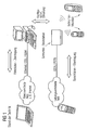
- FIG. 4 shows the realization of the first data sink / source DSQ1 in the FIGURE 2 according to the implementation variant (i) with a cordless telephone SLT as a data terminal device and data transmission device which is connected to the circuit-switched network LVN, and a personal computer PC as a data processing device which is connected to the packet-switched network PVN.
- the personal computer PC has next to a screen BSC (monitor), an input device EV, consisting of a keyboard TA and a "mouse" MA, in a system unit SYE, from the FIGURE 2 known facilities.
- USB interface Universal Serial Bus
- GÜSS2 Universal Serial Bus
- DSL interface Digital Subscriber Line
- NGSS1 USB connection
- the personal computer PC is connected to the cordless telephone SLT.
- the cordless telephone SLT has as a data transmission device a cordless base station SLB and as a data terminal device a cordless handset SLM, which are connected to each other via a radio link FRV1 as the first free space connection.
- the cordless handset SLM has, in addition to a display device AE (display), an input unit EGE embodied as a keyboard and input means EGM consisting of a microphone and a hearing capsule, the first central control unit ZSE1 and, as the first terminal / transmission device interface, a first radio interface EUSS1.
- the display device AE, the input unit EGE and the input means EGM form the in FIGURE 2 represented control means STM.
- the second central control unit ZSE2 having the first switching control means USSM1, the first switching means USM1, a second radio interface EUSS2 formed as the second terminal / transmitter interface, a line circuit NUSS1 formed as the first network / transmission interface, and others are first Device / transmitter interface configured USB interface GÜSS1 arranged.
- the line connection NUSS1 establishes the connection to the circuit-switched network LVN and the USB interface GUSS1 is connected to the USB interface GUSS2 arranged in the personal computer PC via the USB connection USBV, LV2.
- the cordless base station SLB is integrated into the personal computer PC as a cordless data adapter, the second data sink / source DSQ2 is obtained according to FIG FIG. 3 ,
Abstract
Description
Die vorliegende Erfindung betrifft ein Datenverarbeitungs-/Datenübertragungsgerät gemäß dem Oberbegriff des Patentanspruches 1 sowie eine Datenendeinrichtung für ein leitungsvermitteltes Netz und paketvermitteltes Netz sowohl gemäß dem Oberbegriff des Patentanspruches 15 als auch gemäß dem Oberbegriff des Patentanspruches 16.The present invention relates to a data processing / data transmission device according to the preamble of
In Veröffentlichungen zum Thema "Home Networking" oder "Connected Home" oder "Telephony and Control" wird von einer Vernetzung von Geräten des privaten Bereiches wie z.B. Fernseher, Personal Computer und andere Geräte des täglichen Lebens gesprochen. Das Telefon, Festnetztelefon oder Schnurlostelefon, dient dabei vorzugsweise als Netzzugang zum leitungsvermittelten Netz (Sprachnetz). Der Zugang zum paketvermittelten Netz (Datennetz) - z.B. Internetzugang - ist dabei unerheblich und kann auf unterschiedlichen Wegen erfolgen.Publications on "Home Networking" or "Connected Home" or "Telephony and Control" refer to the networking of devices of the private sector such as e.g. TV, personal computer and other everyday devices spoken. The telephone, landline telephone or cordless telephone, preferably serves as network access to the circuit-switched network (voice network). Access to the packet-switched network (data network) - e.g. Internet access - is irrelevant and can be done in different ways.
Die Verbindung zwischen paket- und leitungsvermitteltem Netz ist gemäß
Entscheidend ist aber, dass keine Sprachdaten im paketvermittelten Netz bzw. im Datennetz verarbeitet werden, sondern immer eine logische Verbindung zwischen dem Sprach-Endgerät, dem Schnurlos-Mobilteil, und der Vermittlungsstelle, der Schnurlos-Basisstation, besteht. Es gibt also keine logische Verbindung zwischen dem leitungsvermittelten Sprachnetz und dem paketvermittelten Datennetz (z.B. Internet) in Bezug auf Sprachdaten. Die Nutzung von Sprachdiensten des paketvermittelten Datennetzes (wie z.B. Internettelephonie, Sprachnachrichten) wird derzeit nicht über das an der Schnurlos-Basisstation angemeldete Schnurlos-Mobilteil genutzt.But it is crucial that no voice data in the packet-switched network or in the data network are processed, but always a logical connection between the voice terminal, the cordless handset, and the switching center, the cordless base station consists. Thus, there is no logical connection between the circuit-switched voice network and the packet-switched data network (e.g., Internet) with respect to voice data. The use of voice services of the packet-switched data network (such as internet telephony, voice messages) is currently not used via the cordless handset registered at the cordless base station.
Aus der
Der Router (7) in der druckschriftlichen
- * einen als IP-Switch zum Umkopieren von IP-Paketen ausgebildeten IP-Router (72) mit einer Datenkompressionseinrichtung (721), einer Verschlüsselungseinrichtung (722) und einer Leitungsverbindung (76) zu anderen Routern bzw. Hosts im Internet,
- * eine die Funktion einer Vermittlungsstelle oder einer Telekommunikationsanlage beinhaltende Line-Switching-Einrichtung (73) mit einem digitalen Koppelfeld (731) und einer Leitungsverbindung (75) zum Telefonnetz sowie
- * eine dem Dateneingang (74) nachgeschaltete, als logischen Schalter ausgebildete Steuereinrichtung (71) mit einem Zwischenregister (712) und einer Paketierungs-/Depaketierungseinrichtung (711), wobei die Steuereinrichtung (71) sowohl mit dem IP-Router (72) als auch mit der Line-Switching-Einrichtung (73) verbunden ist und wobei die eingehenden/ankommenden Daten entweder über den IP-Router ins paketvermittelte Netz oder über die Line-Switching-Einrichtung ins leitungsvermittelte gesandt werden, also ein Datenrouting stattfindet, bei dem Daten entsprechend einer eingestellten Vermittlungsart (paket- oder leitungsorientierte Vermittlung) geroutet werden.
- * an IP router (72) designed as an IP switch for copying IP packets with a data compression device (721), an encryption device (722) and a line connection (76) to other routers or hosts on the Internet,
- * a line switching device (73) containing the function of an exchange or a telecommunications system with a digital switching network (731) and a line connection (75) to the telephone network and
- * a data input (74) downstream, designed as a logical switch control device (71) with an intermediate register (712) and a packetizing / depacketizing device (711), wherein the controller (71) is connected to both the IP router (72) and the line switching device (73), and wherein the incoming / incoming data is either be sent via the IP router in the packet-switched network or via the line switching device to the circuit-switched, so a data routing takes place in which data is routed according to a set switching mode (packet or circuit-oriented switching).
Gemäß der druckschriftlichen Figur 7 ist der die Steuereinrichtung (71) umfassende Teil der Funktionalität des Routers (7) in die Datenendeinrichtung (1, 2) integriert und somit findet das Datenrouting in der Datenendeinrichtung statt.According to the printed document 7, the part of the functionality of the router (7) comprising the control device (71) is integrated into the data terminal device (1, 2) and thus the data routing takes place in the data terminal device.
Die der Erfindung zugrundeliegende Aufgabe besteht darin, ein Datenverarbeitungs-/Datenübertragungsgerät und eine Datenendeinrichtung für ein leitungsvermitteltes Netz und paketvermitteltes Netz anzugeben, das bzw. die die logische Trennung zwischen Applikationen, die auf dem leitungsvermittelten Netz, z.B. PSTN, ISDN, basieren, und Applikationen, die auf dem paketvermittelten Netz, z.B. Internet, basieren, aufhebt.The object underlying the invention is to provide a data processing / data transmission device and a data transmission device for a circuit-switched network and packet-switched network, the or the logical separation between applications that on the circuit-switched network, e.g. PSTN, ISDN, and applications running on the packet-switched network, e.g. Internet, based, pick up.
Diese Aufgabe wird ausgehend von dem in dem Oberbegriff des Patentanspruches 1 definierten Datenverarbeitungs-/Datenübertragungsgerät durch die in dem Kennzeichen des Patentanspruches 1 angegebenen Merkmale gelöst.This object is achieved on the basis of the data processing / data transmission device defined in the preamble of
Außerdem wird die Aufgabe sowohl ausgehend von der in dem Oberbegriff des Patentanspruches 15 definierten Datenendeinrichtung durch die in dem Kennzeichen des Patentanspruches 15 angegebenen Merkmale als auch ausgehend von der in dem Oberbegriff des Patentanspruches 16 definierten Datenendeinrichtung durch die in dem Kennzeichen des Patentanspruches 16 angegebenen Merkmale gelöst.In addition, the object is achieved both on the basis of the data terminal defined in the preamble of claim 15 by the features indicated in the characterizing part of claim 15 as well as starting from the data terminal device defined in the preamble of claim 16 by the features specified in the characterizing part of claim 16 ,
Die der Erfindung zugrundeliegende Idee besteht darin, ein als Datenverarbeitungs-/Datenübertragungsgerät bezeichnetes, universell einsetzbares Gerät zur automatischen Verarbeitung von Daten und zum Senden und Empfangen von Daten sowohl in das paketvermittelte bzw. aus dem paketvermittelten Netz als auch in das leitungsvermittelte bzw. aus dem leitungsvermittelten Netz, das sowohl dem paketvermittelten Netz zuordbar als auch mit dem leitungsvermittelten Netz verbindbar ist und dem mindestens eine Datenendeinrichtung zum Senden und Empfangen von Daten in das leitungsvermittelte bzw. aus dem leitungsvermittelten Netz zugeordnet oder zuordbar ist, mit steuerbare Umschaltmittel zu versehen, die derart steuerbar sind, dass die Datenendeinrichtung, die in einem ersten Betriebsmodus über das Datenverarbeitungs-/Datenübertragungsgerät mit dem leitungsvermittelten Netz verbunden ist, aus dem ersten Betriebsmodus in einen zweiten Betriebsmodus, in dem die Datenendeinrichtung über das Datenverarbeitungs-/Datenübertragungsgerät mit dem paketvermittelten Netz verbunden ist, umschaltbar ist und umgekehrt, also ein Betriebsmoduswechsel stattfindet.The idea on which the invention is based is a universally usable device, referred to as a data processing / data transmission device, for the automatic processing of data and for the transmission and reception of data both in the packet-switched or in the packet-switched network and in the circuit-switched or out of the packet circuit-switched network, which is both the packet-switched network assignable and connectable to the circuit-switched network and the at least one data terminal device for sending and receiving data in the circuit-switched or from the circuit-switched network assigned or assignable to be provided with controllable switching means such are controllable that the data terminal device, which is connected in a first operating mode via the data processing / data transmission device to the circuit-switched network, from the first operating mode to a second operating mode in which the data terminal via the Date nverarbeitungs- / data transmission device is connected to the packet-switched network, can be switched and vice versa, ie a mode change takes place.
Gemäß der Ansprüche 2 und 17 ist es dabei von Vorteil, dass mit dem Umschalten eine Priorisierung der Verbindung zum leitungsvermittelten Netz gegenüber dem paketvermittelten Netz vornehmbar ist.According to
Weiterhin ist es gemäß der Ansprüche 4 und 19 vorteilhaft, dass mit dem Umschalten der von der Datenendeinrichtung bislang genutzte Übertragungsweg zum leitungs- oder paketvermittelten Netz auflösbar und stattdessen ein neuer Übertragungsweg zum paket- bzw. leitungsvermittelten Netz einrichtbar ist, um wahlweise Dienste des paket- bzw. leitungsvermittelten Netzes in Anspruch nehmen zu können.Furthermore, it is advantageous in accordance with claims 4 and 19 that, with the switchover of the transmission path previously used by the data terminal to the circuit-switched or packet-switched network, it is possible to set up a new transmission path to the packet-switched or circuit-switched network in order to optionally select services of the packet-switched network. or circuit-switched network to avail.
Die Erfindung besteht in der Erweiterung eines z.B. gemäß Anspruch 8 als Settop-Box, Notebook oder Personal Computer ausgebildeten Datenverarbeitungs-/Datenübertragungsgerät, bestehend aus der baulichen Einheit einer Datenübertragungseinrichtung, die z.B. als Schnurlos-Basisstation ausgebildet ist, und einem z.B. mit dem Internet vernetzten Datenverarbeitungsgerät, das vorzugsweise als Personal Computer, Notebook oder Server für den Heim- und/oder den Arbeitsplatzbereich ausgebildet ist, um eine Umschaltmöglichkeit, die gemäß der Ansprüche 10 und 11 vorzugsweise durch Software realisiert ist, so dass durch die in dem Datenverarbeitungs-/Datenübertragungsgerät verarbeiteten Sprach- und/oder Signalisierungsdatenströme neue Applikationen ermöglicht werden. Mit der so geschaffenen baulichen Einheit aus Datenübertragungseinrichtung und Datenverarbeitungsgerät können Internet- oder Personal Computer-basierende Sprach-Applikationen (wie z.B. Internettelephonie, "Voice-Messaging" etc.) durch an dem Datenverarbeitungs-/Datenübertragungsgerät betriebene Datenendeinrichtungen genutzt werden.The invention consists in the extension of an example according to
Dies bedeutet, dass Datenendeinrichtungen, z.B. ein Schnurlos-Mobilteil gemäß dem Anspruch 30 oder ein Telefon, eine logische Verbindung für Sprachdaten in das paketvermittelte Netz, z.B. ins Internet oder in eine lokales Datennetz des "Home Networking"-Szenarios schalten kann.This means that data terminals, e.g. a cordless handset according to claim 30 or a telephone, a logical connection for voice data in the packet-switched network, e.g. into the internet or into a local data network of the "home networking" scenario.
Hierdurch wird vor allem die Benutzerfreundlichkeit erhöht. Die Applikationen, die derzeit mit einer am Personal Computer betriebenen Kopfsprechgarnitur (Headset) möglich sind, können aufgrund der Erfindung auch auf einem Schnurlos-Mobilteil durchgeführt werden.This especially increases the user-friendliness. The applications that are currently possible with a headset operated on the personal computer (headset) can be carried out on a cordless handset due to the invention.
Durch die erfindungsgemäße Umschaltmöglichkeit in dem Datenverarbeitungs-/Datenübertragungsgerät mit integrierter Schnurlos-Basisstation können vom Anwender wahlweise zwei Betriebsmodi am Schnurlos-Mobilteil eingestellt werden.The switching possibility according to the invention in the data processing / data transmission device with integrated cordless base station allows the user optionally to set two operating modes on the cordless handset.
In einem ersten Betriebsmodus arbeitet das Schnurlos-Mobilteil wie ein normales Telefon am leitungsvermittelten Netz.In a first mode of operation, the cordless handset operates like a regular telephone on the circuit switched network.
In einem zweiten Betriebsmodus werden die Sprach- und Protokolldaten über das Datenverarbeitungs-/Datenübertragungsgerät zum Datennetz geleitet. Es besteht dabei keine Verbindung zum leitungsgebundenen Netz. Zusätzlich werden Informationen über Benutzereingaben am Schnurlos-Mobilteil an den Personal Computer des Datenverarbeitungs-/Datenübertragungsgerätes weitergeleitet und Anzeigeinformationen an das Schnurlos-Mobilteil vom Personal Computer des Datenverarbeitungs-/Datenübertragungsgerätes gesendet. Außerdem werden die Sprachkanäle transparent, über eine sogenannte Tunnelverbindung zum Personal Computer des Datenverarbeitungs-/Datenübertragungsgerätes geschaltet.In a second mode of operation, the voice and log data are transmitted via the data processing / communication device directed to the data network. There is no connection to the wired network. In addition, information about user input on the cordless handset is forwarded to the personal computer of the data processing / data transfer device and display information is sent to the cordless handset by the personal computer of the data processing / data transfer device. In addition, the voice channels are transparent, connected via a so-called tunnel connection to the personal computer of the data processing / data transmission device.
Hierdurch kann in dem Datenverarbeitungs-/Datenübertragungsgerät das mit der Schnurlos-Basisstation verbundene Schnurlos-Mobilteil eine auf dem Personal Computer laufende Applikation, wie z.B. eine Kopfsprechgarnitur (Headset) verwenden. Zusätzliche Applikationen können durch Interaktion mit dem Benutzer über Display- und Steuerdaten aktiviert werden, wodurch insbesondere die Benutzerfreundlichkeit weiter erhöht wird. So wird z.B. "Voice over Internet Protocol"-Telefonie (VoIP-Telephonie) mit einem herkömmlichen Schnurlos-Telefon möglich (Telephonie-Funktionalität allen Applikationen in einem Netzwerk (z.B. Personal Computer im Heim-Netz) zur Verfügung zu stellen). Außerdem ist es möglich, das auf diese Weise mit dem herkömmlichen Schnurlos-Telefon beispielsweise Online-Spiele durchgeführt, Sprachsteuerungen im Heim-Netz realisiert und Geräte im Heim-Netz fernbedient werden können.In this way, in the data processing / data transmission device, the cordless handset connected to the cordless base station can receive an application running on the personal computer, such as a personal computer. use a headset. Additional applications can be activated through interaction with the user via display and control data, which further enhances user-friendliness in particular. For example, Voice over Internet Protocol (VoIP) telephony is possible with a conventional cordless telephone (providing telephony functionality to all applications in a network (e.g., personal computers in the home network)). In addition, it is possible that in this way with the conventional cordless telephone, for example, online games can be performed, implemented voice control in the home network and devices in the home network can be remotely controlled.
Mit der Erfindung ist es beispielsweise auch möglich, konventionelle Schnurlostelefone in ein "Connected Home"-Szenario zu integrieren. Hierbei dient der Personal Computer für die "VoIP-Telephonie" als "VoIP-Gateway". Ebenso ist eine Integration in die Spiele-Konsolen, wie z.B. die X-Box, möglich.For example, it is also possible with the invention to integrate conventional cordless telephones into a connected home scenario. Here, the personal computer is used for the "VoIP telephony" as a "VoIP gateway". Likewise, integration into the game consoles, e.g. the X-Box, possible.
Weiterhin bietet die Erfindung die Möglichkeit, Applikationen des Datenverarbeitungs-/Datenübertragungsgerät durch die Datenendeinrichtung basierend auf Sprachsteuerungs- und Spracherkennungsmechanismen (Voice Control and Voice Recognition) zu steuern, die Datenendeinrichtung als Fernsteuerungseinheit (Remote Control Unit) zu nutzen, den Zugang zum Messenger-Service von Microsoft über die Datenendeinrichtung herzustellen, ein Internet-Radio zu realisieren, Internet-Chatten mittels Schnurlos-Mobilteil oder Telefon durchzuführen, die Umsetzung von Textnachrichten in Sprachnachrichten ("Text to Speech") damit z.B. E-Mails vorgelesen werden können und/oder die Darstellung von Nachrichten auf dem Display der Datenendeinrichtung zu nutzen.Furthermore, the invention offers the possibility of applications of the data processing / data transmission device by the data terminal device based on voice control and voice recognition mechanisms (Voice Control and Voice Recognition). to control, use the data terminal as a remote control unit (Remote Control Unit) to establish the access to Microsoft's messenger service via the data terminal, to realize an Internet radio to perform Internet chats using cordless handset or telephone, the implementation of text messages in voice messages ("Text to Speech") so that, for example, e-mails can be read and / or use the display of messages on the display of the data terminal.
Die Erfindung ist aber nicht nur für den Heimbereich wie vorstehend erläutert anwendbar, wenn in dem Datenverarbeitungs-/Datenübertragungsgerät die Datenübertragungseinrichtung als Schnurlos-Basisstation und das Datenverarbeitungsgerät als Personal Computer oder Server ausgebildet sind, und die Datenendeinrichtung als Schnurlos-Mobilteil ausgebildet ist, sondern ist auch ohne weiteres für den öffentlichen Bereich, wenn in dem Datenverarbeitungs-/Datenübertragungsgerät die Datenübertragungseinrichtung als zellulare Mobilfunkinfrastruktur bestehend aus Basisstation und zentrale Vermittlungsanlage und das Datenverarbeitungsgerät als Server ausgebildet sind, und die Datenendeinrichtung als Mobilfunktelefon (Handy) ausgebildet ist, anwendbar.However, the invention is applicable not only to the home field as explained above, when in the data processing / data transmission device, the data transmission device is designed as a cordless base station and the data processing device as a personal computer or server, and the data terminal is designed as a cordless handset, but is also readily for the public sector, if in the data processing / data transmission device, the data transmission device as a cellular mobile radio infrastructure consisting of base station and central switching system and the data processing device are designed as servers, and the data terminal is designed as a mobile phone (mobile phone) applicable.
Weitere vorteilhafte Weiterbildungen der Erfindung sind den übrigen Unteransprüchen und der nachfolgenden Beschreibung eines Ausführungsbeispiels der Erfindung zu entnehmen.Further advantageous developments of the invention can be taken from the remaining subclaims and the following description of an exemplary embodiment of the invention.
Das Ausführungsbeispiel der Erfindung wird anhand der
-
FIGUR 2 eine erste Datensenke/-quelle für ein leitungsvermitteltes Netz und paketvermitteltes Netz bestehend aus einer Datenendeinrichtung, einer Datenübertragungseinrichtung und einem als Datenverarbeitungsgerät bezeichneten universell einsetzbaren Gerät zur automatischen Verarbeitung von Daten und zum Senden und Empfangen von Daten in das paketvermittelte bzw. aus dem paketvermittelten Netz, -
FIGUR 3 ausgehend vonFIGUR 2 eine zweite Datensenke/-quelle für ein leitungsvermitteltes Netz und paketvermitteltes Netz bestehend aus einer Datenendeinrichtung und einem als Datenverarbeitungs-/Datenübertragungsgerät bezeichneten universell einsetzbaren Gerät DVÜG zur automatischen Verarbeitung von Daten und zum Senden und Empfangen von Daten sowohl in das paketvermittelte bzw. aus dem paketvermittelten Netz als auch in das leitungsvermittelte bzw. aus dem leitungsvermittelten Netz, -
FIGUR 4 Realisierung der ersten Datensenke/-quelle mit einem Schnurlostelefon und einem Personal Computer. -
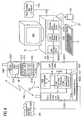
FIGUR 2 zeigt eine erste Datensenke/-quelle DSQ1 für ein vorzugsweise als "Public Switched Telephone Network (PSTN)" oder "Integrated Services Digital Network (ISDN)" ausgebildetes leitungsvermitteltes Netz LVN und ein vorzugsweise als Internet ausgebildetes paketvermitteltes Netz PVN bestehend aus einer Datenendeinrichtung DEE, einer Datenübertragungseinrichtung DÜE und einem als Datenverarbeitungsgerät bezeichneten universell einsetzbaren Gerät DVG zur automatischen Verarbeitung von Daten und zum Senden und Empfangen von Daten in das paketvermittelte bzw. aus dem paketvermittelten Netz.
-
FIGURE 2 a first data sink / source for a circuit-switched network and packet-switched network consisting of a data terminal device, a data transmission device and a universally usable device designated as a data processing device for automatic processing of data and for sending and receiving data in the packet-switched or from the packet-switched network, -
FIG. 3 starting fromFIGURE 2 a second data sink / source for a circuit-switched network and packet-switched network consisting of a data terminal and a data processing / data transfer device called universally applicable device DVÜG for automatic processing of data and for sending and receiving data both in the packet-switched or from the packet-switched Network as well as in the circuit-switched or from the circuit-switched network, -
FIG. 4 Realization of the first data sink / source with a cordless telephone and a personal computer. -
FIGURE 2 1 shows a first data sink / source DSQ1 for a circuit-switched network LVN, preferably designed as a "Public Switched Telephone Network (PSTN)" or "Integrated Services Digital Network (ISDN)", and a packet-switched network PVN, preferably designed as Internet, consisting of a data terminal DEE, a data transmission device DÜE and a data processing device designated as universally applicable device DVG for the automatic processing of data and for sending and receiving data in the packet-switched or from the packet-switched network.
Die Datenendeinrichtung DEE enthält eine erste Zentrale Steuereinheit ZSE1, Steuerungsmittel STM und eine erste Endeinrichtungs-/Übertragungseinrichtungsschnittstelle EÜSS1. Die erste Zentrale Steuereinheit ZSE1, dient zur Steuerung der Funktionsabläufe in der Datenendeinrichtung DEE und ist sowohl mit den Steuerungsmitteln STM als auch mit der ersten Endeinrichtungs-/Übertragungseinrichtungsschnittstelle EÜSS1 verbunden. Über die erste Endeinrichtungs-/Übertragungseinrichtungsschnittstelle EÜSS1 ist die Datenendeinrichtung DEE mit der Datenübertragungseinrichtung DÜE verbunden, die für diese Verbindung eine zweite Endeinrichtungs-/Übertragungseinrichtungsschnittstelle EÜSS2 aufweist. Als Verbindung zwischen der Datenendeinrichtung DEE und der Datenübertragungseinrichtung DÜE ist entweder eine erste Leitungsverbindung LV1 oder eine erste Freiraumverbindung FRV1 vorgesehen.The data terminal DEE contains a first central control unit ZSE1, control means STM and a first terminal / transmitter interface EUSS1. The first central control unit ZSE1 serves to control the functional sequences in the data terminal DEE and is connected both to the control means STM and to the first terminal / transmission interface EÜSS1. Via the first terminal / transmission device interface EÜSS1, the data terminal DEE is connected to the data transmission device DÜE, which has a second terminal / transmission device interface EÜSS2 for this connection. As a connection between the data terminal DEE and the data transmission device DÜE is provided either a first line connection LV1 or a first free space connection FRV1.
Die Datenübertragungseinrichtung DÜE enthält neben der zweiten Endeinrichtungs-/Übertragungseinrichtungsschnittstelle EÜSS2 noch eine zweite Zentrale Steuereinheit ZSE2, eine erste Netz-/Übertragungseinrichtungsschnittstelle NÜSS1, erste Umschaltmittel USM1 und eine erste Geräte-/Übertragungseinrichtungsschnittstelle GÜSS1. Die zweite Zentrale Steuereinheit ZSE2, die zur Steuerung der Funktionsabläufe in der Datenübertragungseinrichtung DÜE dient und erste Umschaltsteuerungsmittel USSM1 aufweist, ist mit der zweiten Endeinrichtungs-/Übertragungseinrichtungsschnittstelle EÜSS2, der ersten Netz-/Übertragungseinrichtungsschnittstelle NÜSS1 und der ersten Geräte-/Übertragungseinrichtungsschnittstelle GÜSS1 verbunden. Die ersten Umschaltsteuerungsmittel USSM1 der zweiten Zentralen Steuereinheit ZSE2 bilden mit den ersten Umschaltmitteln USM1 eine Funktionseinheit derart, dass die Umschaltsteuerungsmittel USSM1 die Umschaltmittel USM1 steuern, was in der
Das Datenverarbeitungsgerät DVG enthält neben der zweiten Geräte-/Übertragungseinrichtungsschnittstelle GÜSS2 noch eine dritte Zentrale Steuereinheit ZSE3 und eine erste Netz-/Geräteschnittstelle NGSS1. Die dritte Zentrale Steuereinheit ZSE3, die zur Steuerung der Funktionsabläufe in dem Datenverarbeitungsgerät DVG dient und zusätzlich zu den ersten Umschaltsteuerungsmittel USSM1 der zweiten Zentralen Steuereinheit ZSE2 in der Datenübertragungseinrichtung DÜE optional in der
Im folgenden wird basierend auf der Erläuterung des Aufbaus der ersten Datensenke/-quelle DSQ1 die Funktionsweise der Datensenke/-quelle DSQ1 im Hinblick auf die Beseitigung der logische Trennung zwischen ersten Applikationen, die auf dem leitungsvermittelten Netz LVN basieren, und zweiten Applikationen, die auf dem paketvermittelten Netz PVN basieren, erläutert.Hereinafter, based on the explanation of the construction of the first data sink / source DSQ1, the operation of the data sink / source DSQ1 will be described with respect to the elimination of the logical separation between first applications based on the circuit-switched network LVN and second applications based on based on the packet-switched network PVN explained.
Aus der Sicht der Datenendeinrichtung DEE, die beispielsweise bislang über die erste Leitungsverbindung LV1 oder die erste Freiraumverbindung FRV1 und die Datenübertragungseinrichtung DÜE mit dem leitungsvermittelten Netz LVN verbunden gewesen ist (vgl. Schnurlos-Basisstation als Datenübertragungseinrichtung und Schnurlos-Mobilteil als Datenendeinrichtung in
Aufgrund der für das angegebene bekannte Szenario (Datenendeinrichtung ↔ leitungsvermittelte Netz) bereits bestehenden Verbindung zwischen der Datenendeinrichtung DEE und der Datenübertragungseinrichtung DÜE sind zu diesem Zweck in der Datenübertragungseinrichtung DÜE die ersten Umschaltmittel USM1 und die ersten Umschaltsteuerungsmittel USSM1, in dem Datenverarbeitungsgerät DVG gegebenenfalls die zweiten Umschaltsteuerungsmittel USSM2 und in der Datenendeinrichtung DEE die Steuerungsmittel STM vorhanden. Die genannten Mittel sind abgesehen von den Steuerungsmitteln STM in der Datenendeinrichtung DEE, die vorzugsweise als Tastatur ausgebildet sind, allesamt vorzugsweise als Programmmodule (Software) ausgebildet. An die Stelle der Tastatur ist es aber auch möglich, eine Sprachsteuerung zu verwenden.Due to the already existing connection between the data terminal DEE and the data transmission device DÜE for the specified known scenario (data transmission device ↔ circuit-switched network), the first switching means USM1 and the first switching control means USSM1 are in the data transmission device DÜE for this purpose, and the second switching control means in the data processing device DVG if necessary USSM2 and in the data terminal DEE the control means STM available. The said means are apart from the control means STM in the data terminal DEE, which are preferably designed as a keyboard, all preferably designed as program modules (software). In place of the keyboard, it is also possible to use a voice control.
Für jedes andere denkbare Szenario kann die Verteilung der genannten Mittel jedoch z.B. wieder anders sein. So z.B. bei einem Szenario (Datenendeinrichtung ↔ paketvermittelte Netz), wenn die Datenendeinrichtung beispielsweise über eine Leitungsverbindung oder eine Freiraumverbindung und dem Datenverarbeitungsgerät mit dem paketvermittelten Netz verbunden ist. In diesem Fall sind die Umschaltmittel und die Umschaltsteuerungsmittel vorzugsweise in dem Datenverarbeitungsgerät, während in der Datenübertragungseinrichtung gegebenenfalls zusätzliche Umschaltsteuerungsmittel vorhanden sind.For any other conceivable scenario, however, the distribution of said means may be e.g. be different again. For example, in a scenario (data terminal ↔ packet-switched network), when the data terminal device is connected to the packet-switched network via, for example, a line connection or a free-space connection and the data processing device. In this case, the switching means and the switching control means are preferably in the data processing apparatus, while additional data transfer control means may be present in the data transmission means.
Alternativ ist auch eine Konfiguration vorstellbar, bei der die Datenübertragungseinrichtung mit dem paketvermitteltem Netz und das Datenverarbeitungsgerät mit dem leitungsvermitteltem Netz verbunden ist.Alternatively, a configuration is conceivable in which the data transmission device is connected to the packet-switched network and the data processing device to the circuit-switched network.
Für das der
- (i) nur die ersten Umschaltsteuerungsmittel USSM1 in der Datenübertragungseinrichtung DÜE vorhanden sind,
- (ii) sowohl die ersten Umschaltsteuerungsmittel USSM1 in der Datenübertragungseinrichtung DÜE als auch die zweiten Umschaltsteuerungsmittel USSM2 in dem Datenverarbeitungsgerät DVG vorhanden sind, wobei beide Umschaltsteuerungsmittel USSM1, USSM2 die ersten Umschaltmittel USM1 in der Datenübertragungseinrichtung DÜE steuern,
- (iii) sowohl die ersten Umschaltsteuerungsmittel USSM1 in der Datenübertragungseinrichtung DÜE als auch die zweiten Umschaltsteuerungsmittel USSM2 in dem Datenverarbeitungsgerät DVG vorhanden sind, wobei jedoch im Unterschied zu (ii) nur die ersten Umschaltsteuerungsmittel USSM1 die ersten Umschaltmittel USM1 in der Datenübertragungseinrichtung DÜE steuern,
- (i) only the first switching control means USSM1 are present in the data transmission device DÜE,
- (ii) both the first switching control means USSM1 in the data transmission device DÜE and the second switching control means USSM2 are present in the data processing device DVG, both switching control means USSM1, USSM2 controlling the first switching means USM1 in the data transmission device DÜE,
- (iii) both the first switching control means USSM1 in the data transmission device DÜE and the second switching control means USSM2 are present in the data processing device DVG, however, unlike (ii), only the first switching control means USSM1 controls the first switching means USM1 in the data transmission device DÜE,
Für die Beschreibung dieser Realisierungsvariante sei nun angenommen, dass sich die Datenendeinrichtung DEE beispielsweise in dem ersten Betriebsmodus befindet, gemäß dem die Datenendeinrichtung DEE über die Datenübertragungseinrichtung DÜE mit dem leitungsvermittelten Netz LVN verbunden ist. Selbstverständlich ist auch der andere Fall möglich, bei dem sich die Datenendeinrichtung DEE in dem zweiten Betriebsmodus befindet.For the description of this implementation variant, it is now assumed that the data terminal DEE is located, for example, in the first operating mode, according to which the data terminal DEE is connected via the data transmission device DÜE to the circuit-switched network LVN. Of course, the other case is possible in which the data terminal DEE is in the second operating mode.
Der Benutzer der Datenendeinrichtung DEE möchte nun in den zweiten Betriebsmodus wechseln. Der angesprochene Betriebmoduswechsel wird von dem Benutzer der Datenendeinrichtung DEE dadurch eingeleitet, dass dieser die Steuerungsmittel STM betätigt. Daraufhin wird gesteuert durch die erste Zentrale Steuereinheit ZSE1 über diese und die erste Endeinrichtungs-/Übertragungseinrichtungsschnittstelle EÜSS1 ein erstes Signal S1 zur Signalisierung des Betriebsmoduswechsels von der Datenendeinrichtung DEE über die erste Leitungsverbindung LV1 bzw. die erste Freiraumverbindung FRV1 an die zweite Endeinrichtungs-/Übertragungseinrichtungsschnittstelle EÜSS2 in der Datenübertragungseinrichtung DÜE übertragen, die das von der Datenendeinrichtung DEE übertragene erste Signal S1 an die ersten Umschaltsteuerungsmittel USSM1 weiterleitet.The user of the data terminal DEE now wants to change to the second operating mode. The mentioned operating mode change is initiated by the user of the data terminal DEE in that it actuates the control means STM. Thereafter, a first signal S1 for signaling the mode change from the first central control unit ZSE1 via this and the first terminal / transmission interface EÜSS1 is controlled by the first control unit ZSE1 Data terminal DEE via the first line connection LV1 and the first free space connection FRV1 to the second terminal / transmission device interface EUSS2 in the data transmission device DÜE transmitted, which forwards the data signal from the terminal DEE transmitted first signal S1 to the first switching control means USSM1.
Die ersten Umschaltsteuerungsmittel USSM1 erzeugen daraufhin ein zweites Signal S2, das sie an das Datenverarbeitungsgerät DVG und dort insbesondere an die dritte Zentrale Steuereinheit ZSE3 übertragen und mit dem das Datenverarbeitungsgerät DVG darüber informiert wird, dass die Datenendeinrichtung DEE über das Datenverarbeitungsgerät DVG eine Verbindung zum paketvermittelten Netz PVN aufbauen möchte. Nachdem das Datenverarbeitungsgerätes DVG informiert worden ist, erzeugen die ersten Umschaltsteuerungsmittel USSM1 ein drittes Signal S3 und übertragen dieses an die ersten Umschaltmittel USM1. Mit der Übertragung des dritten Signals S3 werden die ersten Umschaltmittel USM1 angewiesen, den von der Datenendeinrichtung DEE bislang genutzten Übertragungsweg zum leitungsvermittelten Netz LVN aufzulösen und stattdessen einen neuen Übertragungsweg über das Datenverarbeitungsgerät DVG zum paketvermittelten Netz PVN einzurichten. In der
Um den Benutzer der Datenendeinrichtung darüber zu informieren, in welchem Betriebsmodus sich die Datenendeinrichtung befindet, wird der jeweilige aktivierte Betriebsmodus vorzugsweise auf einem Display der Datenendeinrichtung angezeigt (vgl.
Für die Beschreibung dieser Realisierungsvariante sei nun wieder angenommen, dass sich die Datenendeinrichtung DEE beispielsweise in dem ersten Betriebsmodus befindet, gemäß dem die Datenendeinrichtung DEE über die Datenübertragungseinrichtung DÜE mit dem leitungsvermittelten Netz LVN verbunden ist. Selbstverständlich ist auch wieder der andere Fall möglich, bei dem sich die Datenendeinrichtung DEE in dem zweiten Betriebsmodus befindet.For the description of this implementation variant, it is again assumed that the data terminal DEE is located, for example, in the first operating mode, according to which the data terminal DEE is connected to the circuit-switched network LVN via the data transmission device DÜE. Of course, the other case is possible again, in which the data terminal DEE is in the second operating mode.
Der Benutzer der Datenendeinrichtung DEE möchte nun in den zweiten Betriebsmodus bzw. den ersten Betriebsmodus wechseln. Der jeweilige Betriebmoduswechsel wird von dem Benutzer der Datenendeinrichtung DEE dadurch eingeleitet, dass dieser die Steuerungsmittel STM betätigt. Für jeden Wechsel kann dies z.B. immer ein und dieselbe Taste bzw. Softkey-Taste sein oder es können für beide Betriebsmoduswechsel auch unterschiedliche Tasten verwendet werden. Bei der Sprachsteuerung hingegen ist die Sache eindeutig, weil immer der gesprochene Betriebsmoduswechsel umgesetzt wird.The user of the data terminal DEE now wants to change to the second operating mode or the first operating mode. The respective mode change is initiated by the user of the data terminal DEE in that it actuates the control means STM. For example, this can always be one and the same key or soft key for each change, or different keys can be used for both operating mode changes. In speech control, on the other hand, the matter is clear because the spoken operating mode change is always implemented.
Daraufhin wird gesteuert durch die erste Zentrale Steuereinheit ZSE1 über diese und die erste Endeinrichtungs-/Übertragungseinrichtungsschnittstelle EÜSS1 ein viertes Signal S4 zur Signalisierung des Betriebsmoduswechsels von der Datenendeinrichtung DEE über die erste Leitungsverbindung LV1 bzw. die erste Freiraumverbindung FRV1 an die zweite Endeinrichtungs-/Übertragungseinrichtungsschnittstelle EÜSS2 in der Datenübertragungseinrichtung DÜE übertragen, über die das von der Datenendeinrichtung DEE übertragene vierte Signal S4 im Fall des Wechsels zum zweiten Betriebsmodus (der aktuelle Betriebsmodus ist demnach der erste Betriebsmodus) an die ersten Umschaltsteuerungsmittel USSM1 weitergeleitet wird und im Fall des Wechsels zum ersten Betriebsmodus (der aktuelle Betriebsmodus ist demnach der zweite Betriebsmodus) über die erste Geräte-/Übertragungseinrichtungsschnittstelle GÜSS1, die zweite Leitungsverbindung LV2 bzw. die zweite Freiraumverbindung FRV2 sowie die zweite Geräte-/Übertragungseinrichtungsschnittstelle GÜSS2 in der genannten Reihenfolge an die zweiten Umschaltsteuerungsmittel USSM2 in dem Datenverarbeitungsgerät DVG weitergeleitet wird.Thereupon, a fourth signal S4 for signaling the mode change from the data terminal DEE via the first line connection LV1 or the first free space connection FRV1 to the second end device / transmission interface EÜSS2 is controlled by the first central control unit ZSE1 via this and the first terminal / transmission device interface EÜSS1 in the data transmission device DUE, via which the fourth signal S4 transmitted by the data terminal device DE4 is forwarded to the first switching control means USSM1 in the case of the change to the second operating mode (the current operating mode is therefore the first operating mode) and in the case of the change to the first operating mode (FIG. the current operating mode is therefore the second operating mode) via the first device / transmission interface GÜSS1, the second line connection LV2 and the second free space connection FRV2 and the second G, respectively device / transmission interface GÜSS2 is forwarded in the order mentioned to the second switching control means USSM2 in the data processing device DVG.
Die das vierte Signal S4 empfangenden ersten bzw. zweiten Umschaltsteuerungsmittel USSM1, USSM2 erzeugen daraufhin jeweils ein fünftes Signal S5, mit dem die jeweils anderen Umschaltsteuerungsmittel USSM2, USSM1 über den jeweiligen Betriebsmoduswechsel informiert werden. Das fünfte Signal S5 wird über die erste Geräte-/Übertragungseinrichtungsschnittstelle GÜSS1, die zweite Leitungsverbindung LV2 bzw. die zweite Freiraumverbindung FRV2 sowie die zweite Geräte-/Übertragungseinrichtungsschnittstelle GÜSS2 oder in umgekehrter Richtung an die betreffenden Umschaltsteuerungsmittel USSM2, USSM1 übertragen. Nachdem die betreffenden Umschaltsteuerungsmittel USSM2, USSM1 und damit das Datenverarbeitungsgerät DVG bzw. die Datenübertragungseinrichtung DÜE über den Betriebsmoduswechsel informiert worden sind, erzeugen die das vierte Signal S4 empfangenden ersten bzw. zweiten Umschaltsteuerungsmittel USSM1, USSM2 jeweils ein sechstes Signal S6 und übertragen dieses an die ersten Umschaltmittel USM1. Im Fall des Wechsels zum zweiten Betriebsmodus erzeugen die ersten Umschaltsteuerungsmittel USSM1 das sechste Signal S6, während im Fall des Wechsels zum ersten Betriebsmodus die zweiten Umschaltsteuerungsmittel USSM2 das sechste Signal S6 erzeugen. Mit der Übertragung des sechsten Signals S6 werden die ersten Umschaltmittel USM1 angewiesen, den von der Datenendeinrichtung DEE bislang genutzten Übertragungsweg zum leitungsvermittelten Netz LVN bzw. paketvermittelten Netz PVN aufzulösen und stattdessen einen neuen Übertragungsweg über das Datenverarbeitungsgerät DVG zum paketvermittelten Netz PVN bzw. über die Datenübertragungseinrichtung DÜE zum leitungsvermittelten Netz LVN einzurichten. In der
Um den Benutzer darüber zu informieren, in welchem Betriebsmodus sich die Datenendeinrichtung befindet, wird wieder der jeweilige aktivierte Betriebsmodus vorzugsweise auf einem Display der Datenendeinrichtung DEE angezeigt (vgl.
Für die Beschreibung dieser Realisierungsvariante sei nun wieder angenommen, dass sich die Datenendeinrichtung DEE beispielsweise in dem ersten Betriebsmodus befindet, gemäß dem die Datenendeinrichtung DEE über die Datenübertragungseinrichtung DÜE mit dem leitungsvermittelten Netz LVN verbunden ist. Selbstverständlich ist auch wieder der andere Fall möglich, bei dem sich die Datenendeinrichtung DEE in dem zweiten Betriebsmodus befindet.For the description of this implementation variant, it is again assumed that the data terminal DEE is located, for example, in the first operating mode, according to which the data terminal DEE is connected to the circuit-switched network LVN via the data transmission device DÜE. Of course, the other case is possible again, in which the data terminal DEE is in the second operating mode.
Der Benutzer der Datenendeinrichtung DEE möchte nun in den zweiten Betriebsmodus bzw. den ersten Betriebsmodus wechseln. Der jeweilige Betriebmoduswechsel wird von dem Benutzer der Datenendeinrichtung DEE dadurch eingeleitet, dass dieser die Steuerungsmittel STM betätigt. Für jeden Wechsel kann dies z.B. immer ein und dieselbe Taste bzw. Softkey-Taste sein oder es können für beide Betriebsmoduswechsel auch unterschiedliche Tasten verwendet werden. Bei der Sprachsteuerung hingegen ist die Sache eindeutig, weil immer der gesprochene Betriebsmoduswechsel umgesetzt wird.The user of the data terminal DEE now wants to change to the second operating mode or the first operating mode. The respective mode change is initiated by the user of the data terminal DEE in that it actuates the control means STM. For each change this may e.g. always one and the same key or soft key, or different keys can be used for both operating mode change. In speech control, on the other hand, the matter is clear because the spoken operating mode change is always implemented.
Daraufhin wird wieder gesteuert durch die erste Zentrale Steuereinheit ZSE1 über diese und die erste Endeinrichtungs-/Übertragungseinrichtungsschnittstelle EÜSS1 wieder das vierte Signal S4 zur Signalisierung des Betriebsmoduswechsels von der Datenendeinrichtung DEE über die erste Leitungsverbindung LV1 bzw. die erste Freiraumverbindung FRV1 an die zweite Endeinrichtungs-/Übertragungseinrichtungsschnittstelle EÜSS2 in der Datenübertragungseinrichtung DÜE übertragen, über die das von der Datenendeinrichtung DEE übertragene vierte Signal S4 im Fall des Wechsels zum zweiten Betriebsmodus (der aktuelle Betriebsmodus ist demnach der erste Betriebsmodus) wieder an die ersten Umschaltsteuerungsmittel USSM1 weitergeleitet wird und im Fall des Wechsels zum ersten Betriebsmodus (der aktuelle Betriebsmodus ist demnach der zweite Betriebsmodus) wieder über die erste Geräte-/Übertragungseinrichtungsschnittstelle GÜSS1, die zweite Leitungsverbindung LV2 bzw. die zweite Freiraumverbindung FRV2 sowie die zweite Geräte-/Übertragungseinrichtungsschnittstelle GÜSS2 in der genannten Reihenfolge wieder an die zweiten Umschaltsteuerungsmittel USSM2 in dem Datenverarbeitungsgerät DVG weitergeleitet wird.The first control unit ZSE1 is then again controlled by this and the first terminal / transmission interface EUSS1 again the fourth signal S4 for signaling the mode change from the data terminal DEE via the first line connection LV1 and the first free space connection FRV1 to the second terminal / Transfer device interface EÜSS2 transmitted in the data transmission device DÜE over which the fourth signal S4 transmitted by the data terminal DEE in the case of the change to the second operating mode (the current operating mode is therefore the first operating mode) is forwarded again to the first switching control means USSM1 and in the case of change to the first operating mode (the current operating mode is therefore the second operating mode ) again via the first device / transmission interface GÜSS1, the second line connection LV2 or the second free space connection FRV2 and the second device / transmission interface GÜSS2 in the order mentioned is forwarded again to the second switching control means USSM2 in the data processing device DVG.
Die das vierte Signal S4 empfangenden ersten Umschaltsteuerungsmittel USSM1 erzeugen daraufhin ein siebtes Signal S7, mit dem diese die zweiten Umschaltsteuerungsmittel USSM2 über den ihnen signalisierten Betriebsmoduswechsel informieren. Das siebte Signal S7 wird über die erste Geräte-/Übertragungseinrichtungsschnittstelle GÜSS1, die zweite Leitungsverbindung LV2 bzw. die zweite Freiraumverbindung FRV2 sowie die zweite Geräte-/Übertragungseinrichtungsschnittstelle GÜSS2 an die zweiten Umschaltsteuerungsmittel USSM2 übertragen. Nachdem die zweiten Umschaltsteuerungsmittel USSM2 und damit das Datenverarbeitungsgerät DVG über den Betriebsmoduswechsel informiert worden sind, erzeugen die das siebte Signal S7 empfangenden zweiten Umschaltsteuerungsmittel USSM2 ein achtes Signal S8 und übertragen dieses über die zweite Geräte-/Übertragungseinrichtungsschnittstelle GÜSS2, die zweite Leitungsverbindung LV2 bzw. die zweite Freiraumverbindung FRV2 sowie die erste Geräte-/Übertragungseinrichtungsschnittstelle GÜSS1 in der genannten Reihenfolge an die ersten Umschaltsteuerungsmittel USSM1. Mit diesem achten Signal S8 signalisieren die zweiten Umschaltsteuerungsmittel USSM2 den ersten Umschaltsteuerungsmittel USSM1, dass diese den Wechsel von dem zweiten Betriebsmodus in den ersten Betriebsmodus den ersten Umschaltmitteln USM1 signalisieren und somit steuern sollen. Die ersten Umschaltsteuerungsmittel USSM1 erzeugen daraufhin ein neuntes Signal S9 und übertragen dieses an die ersten Umschaltmittel USM1. Mit der Übertragung des neunten Signals S9 werden die ersten Umschaltmittel USM1 angewiesen, den von der Datenendeinrichtung DEE bislang genutzten Übertragungsweg zum leitungsvermittelten Netz LVN bzw. paketvermittelten Netz PVN aufzulösen und stattdessen einen neuen Übertragungsweg über das Datenverarbeitungsgerät DVG zum paketvermittelten Netz PVN bzw. über die Datenübertragungseinrichtung DÜE zum leitungsvermittelten Netz LVN einzurichten. In der
Um den Benutzer darüber zu informieren, in welchem Betriebsmodus sich die Datenendeinrichtung befindet, wird wieder der jeweilige aktivierte Betriebsmodus vorzugsweise auf einem Display der Datenendeinrichtung DEE angezeigt (vgl.
Bei den vorgestellten Realisierungsvarianten (i), (ii) und (iii) ist es von Vorteil, wenn die mit den Signalen S2, S5, S7, S8 signalisierten Betriebsmoduswechsel von den diese Signale empfangenden Umschaltsteuerungsmitteln jeweils mit einem zehnten Signal S10 bestätigt werden, bevor der Betriebsmoduswechsel durch die ersten Umschaltmittel USM1 durchgeführt wird.In the presented realization variants (i), (ii) and (iii), it is advantageous if the operating mode changes signaled by the signals S2, S5, S7, S8 are respectively confirmed by the switching control means receiving these signals with a tenth signal S10 before the operating mode change is performed by the first switching means USM1.
Die Datenendeinrichtung DEE enthält die erste Zentrale Steuereinheit ZSE1, die Steuerungsmittel STM und die erste Endeinrichtungs-/Übertragungseinrichtungsschnittstelle EÜSS1. Die erste Zentrale Steuereinheit ZSE1, dient zur Steuerung der Funktionsabläufe in der Datenendeinrichtung DEE und ist sowohl mit den Steuerungsmitteln STM als auch mit der ersten Endeinrichtungs-/Übertragungseinrichtungsschnittstelle EÜSS1 verbunden. Über die erste Endeinrichtungs-/Übertragungseinrichtungsschnittstelle EÜSS1 ist die Datenendeinrichtung DEE mit dem Datenverarbeitungs-/Datenübertragungsgerät DVÜG verbunden, das für diese Verbindung eine dritte Endeinrichtungs-/Übertragungseinrichtungsschnittstelle EÜSS3 aufweist. Als Verbindung zwischen der Datenendeinrichtung DEE und dem Datenverarbeitungs-/Datenübertragungsgerät DVÜG ist entweder wieder die erste Leitungsverbindung LV1 oder die erste Freiraumverbindung FRV1 vorgesehen.The data terminal DEE contains the first central control unit ZSE1, the control means STM and the first terminal / transmitter interface EUSS1. The first central control unit ZSE1 serves to control the functional sequences in the data terminal DEE and is connected both to the control means STM and to the first terminal / transmission interface EÜSS1. The data terminal DEE is via the first terminal / transmission interface EÜSS1 connected to the data processing / data transmission device DVÜG, which has a third end device / transmission interface EÜSS3 for this connection. As the connection between the data terminal DEE and the data processing / data transmission device DVÜG either the first line connection LV1 or the first free space connection FRV1 is again provided.
Das Datenverarbeitungs-/Datenübertragungsgerät DVÜG enthält neben der dritten Endeinrichtungs-/Übertragungseinrichtungsschnittstelle EÜSS3 noch eine vierte Zentrale Steuereinheit ZSE4, eine zweite Netz-/Übertragungseinrichtungsschnittstelle NÜSS2, zweite Umschaltmittel USM2 und eine zweite Netz-/Geräteschnittstelle NGSS2. Die vierte Zentrale Steuereinheit ZSE4, die zur Steuerung der Funktionsabläufe in dem Datenverarbeitungs-/Datenübertragungsgerät DVÜG dient und dritte Umschaltsteuerungsmittel USSM3 aufweist, ist mit der dritten Endeinrichtungs-/Übertragungseinrichtungsschnittstelle EÜSS3, der zweiten Netz-/Übertragungseinrichtungsschnittstelle NÜSS2 und der zweiten Netz-/Geräteschnittstelle NGSS2 verbunden.The data processing / data transmission device DVÜG contains, in addition to the third terminal / transmission device interface EÜSS3, a fourth central control unit ZSE4, a second network / transmission interface NUSS2, second switching means USM2 and a second network / device interface NGSS2. The fourth central control unit ZSE4, which is for controlling the operations in the data processing / data transmission device DVÜG and has third switching control means USSM3, is provided with the third terminal / transmission interface EUSS3, the second network interface NUSS2, and the second network / device interface NGSS2 connected.
Die dritten Umschaltsteuerungsmittel USSM3 der vierten Zentralen Steuereinheit ZSE4 bilden mit den zweiten Umschaltmitteln USM2 eine Funktionseinheit derart, dass die Umschaltsteuerungsmittel USSM3 die Umschaltmittel USM1 steuern, was in der
Im folgenden wird basierend auf der Erläuterung des Aufbaus der zweiten Datensenke/-quelle DSQ2 die Funktionsweise der Datensenke/-quelle DSQ2 im Hinblick auf die Beseitigung der logische Trennung zwischen ersten Applikationen, die auf dem leitungsvermittelten Netz LVN basieren, und zweiten Applikationen, die auf dem paketvermittelten Netz PVN basieren, erläutert.In the following, based on the explanation of the structure of the second data sink DSQ2, the operation of the data sink DSQ2 will be described with respect to the elimination of the logical separation between first applications based on the circuit-switched network LVN and second applications. which are based on the packet-switched network PVN explained.
Für das in der
Der Benutzer der Datenendeinrichtung DEE möchte nun in den zweiten Betriebsmodus wechseln. Der angesprochene Betriebmoduswechsel wird von dem Benutzer der Datenendeinrichtung DEE dadurch eingeleitet, dass dieser die Steuerungsmittel STM betätigt. Daraufhin wird gesteuert durch die erste Zentrale Steuereinheit ZSE1 über diese und die erste Endeinrichtungs-/Übertragungseinrichtungsschnittstelle EÜSS1 ein elftes Signal S11 zur Signalisierung des Betriebsmoduswechsels von der Datenendeinrichtung DEE über die erste Leitungsverbindung LV1 bzw. die erste Freiraumverbindung FRV1 an die dritte Endeinrichtungs-/Übertragungseinrichtungsschnittstelle EÜSS3 in dem Datenverarbeitungs-/Datenübertragungsgerät DVÜG übertragen, das das von der Datenendeinrichtung DEE übertragene elfte Signal S11 an die dritten Umschaltsteuerungsmittel USSM3 weiterleitet.The user of the data terminal DEE now wants to change to the second operating mode. The mentioned operating mode change is initiated by the user of the data terminal DEE in that it actuates the control means STM. Thereupon, an eleventh signal S11 for signaling the mode change from the data terminal DEE via the first line connection LV1 or the first free space connection FRV1 to the third end device / transmission interface EÜSS3 is controlled by the first central control unit ZSE1 via this and the first terminal / transmission device interface EUSS1 in the data processing / data transmission device DVÜG, which forwards the eleventh signal S11 transmitted by the data transmission device DEE to the third switching control means USSM3.
Die dritten Umschaltsteuerungsmittel USSM3 erzeugen daraufhin ein zwölftes Signal S12 und übertragen dieses an die zweiten Umschaltmittel USM2. Mit der Übertragung des zwölften Signals S12 werden die zweiten Umschaltmittel USM2 angewiesen, den von der Datenendeinrichtung DEE bislang genutzten Übertragungsweg zum leitungsvermittelten Netz LVN aufzulösen und stattdessen einen neuen Übertragungsweg zum paketvermittelten Netz PVN einzurichten. In der
Um den Benutzer der Datenendeinrichtung darüber zu informieren, in welchem Betriebsmodus sich die Datenendeinrichtung befindet, wird der jeweilige aktivierte Betriebsmodus vorzugsweise auf einem Display der Datenendeinrichtung angezeigt (vgl.
Wird die Schnurlos-Basisstation SLB als Schnurlos-Datenadapter in den Personal Computer PC integriert, so erhält man die zweite Datensenke/-quelle DSQ2 gemäß
Claims (31)
dadurch gekennzeichnet, dass
characterized in that
mit dem Umschalten eine Priorisierung der Verbindung zum leitungsvermittelten Netz gegenüber dem paketvermittelten Netz vornehmbar ist.Data processing / data transmission device according to claim 1, characterized in that
with the switching, a prioritization of the connection to the circuit-switched network with respect to the packet-switched network is vornehmbar.
die Priorisierung durch eine zeitgesteuerte Default-Einstellung erreichbar ist, bei der, wenn ein Betriebsmoduswechsel vom ersten Betriebsmodus zum zweiten Betriebsmodus stattgefunden hat und die Datenendeinrichtung (DEE) nach Beenden einer Verbindungssitzung im zweiten Betriebsmodus nicht innerhalb einer vorgegebenen Zeit wieder zurückgesetzt ist, das Zurücksetzen in den ersten Betriebsmodus automatisch erfolgt.Data processing / data transmission device according to claim 2, characterized in that
the prioritization is achievable by a timed default setting in which, when an operating mode change from the first mode of operation to the second mode of operation, and the data terminal (DEE) is not reset within a predetermined time after completing a connection session in the second mode of operation, resetting to the first mode of operation is automatic.
mit dem Umschalten der von der Datenendeinrichtung (DEE) bislang genutzte Übertragungsweg zum leitungs- oder paketvermittelten Netz auflösbar und stattdessen ein neuer Übertragungsweg zum paket- bzw. leitungsvermittelten Netz einrichtbar ist, um wahlweise Dienste des paket- bzw. leitungsvermittelten Netzes in Anspruch nehmen zu können.Data processing / data transmission device according to claim 1, 2 or 3, characterized in that
with the switching of the data transmission device (DEE) previously used transmission path to the circuit or packet-switched network resolvable and instead a new transmission path to the packet or circuit-switched network can be set up to take optional services of the packet or circuit-switched network ,
eine erste Leitungsverbindung (LV1) vorhanden ist, über die das Datenverarbeitungs-/Datenübertragungsgerät (DVÜG) mit der Datenendeinrichtung (DEE) verbunden ist.Data processing / data transmission device according to claim 1, characterized in that
a first line connection (LV1) is provided, via which the data processing / data transmission device (DVÜG) is connected to the data terminal device (DEE).
eine erste Freiraumverbindung (FRV1) vorhanden ist, über die das Datenverarbeitungs-/Datenübertragungsgerät (DVÜG) mit der Datenendeinrichtung (DEE) verbunden ist.Data processing / data transmission device according to claim 1, characterized in that
a first free space connection (FRV1) is provided, via which the data processing / data transmission device (DVÜG) is connected to the data terminal device (DEE).
die Datenendeinrichtung (DEE) zur Bildung einer baulichen, funktionalen Einheit in das Datenverarbeitungs-/Datenübertragungsgerät (DVÜG) integriert ist.Data processing / data transmission device according to claim 1, characterized in that
the data terminal device (DEE) is integrated into the data processing / data transmission device (DVÜG) to form a structural, functional unit.
das Datenverarbeitungs-/Datenübertragungsgerät (DVÜG) als Settop-Box, Notebook oder Personal Computer ausgebildet ist.Data processing / data transmission device according to claim 1, characterized in that
the data processing / data transmission device (DVÜG) is designed as a set-top box, notebook or personal computer.
dritte Umschaltsteuerungsmittel (USSM3) vorhanden sind, die mit den Umschaltmitteln (USM2) sowie Steuerungsmitteln (STM) und einer ersten Zentralen Steuereinheit (ZSE1) in der Datenendeinrichtung (DEE) eine Funktionseinheit bilden, wobei die Funktionseinheit derart beschaffen ist, dass
third switching control means (USSM3) are provided, which with the switching means (USM2) and control means (STM) and a first central control unit (ZSE1) in the data terminal (DEE) form a functional unit, wherein the functional unit is such that
die Umschaltsteuerungsmittel (USSM3) als Software-Module ausgebildet sind.Data processing / data transmission device according to claim 9, characterized in that
the switching control means (USSM3) are designed as software modules.
die dritten Umschaltsteuerungsmittel (USSM3) in einer vierten Zentralen Steuereinheit (ZSE4) zur Steuerung der Funktionsabläufe enthalten sind.Data processing / data transmission device according to claim 9, characterized in that
the third switching control means (USSM3) are included in a fourth central control unit (ZSE4) for controlling the functional processes.
das Datenverarbeitungs-/Datenübertragungsgerät (DVÜG) einen integrierten Schnurlos-Datenadapter aufweist.Data processing / data transmission device according to claim 6, characterized in that
the data processing / data transmission device (DVÜG) has an integrated wireless data adapter.
die Daten als Sprach- und/oder Paketdaten ausgebildet sind.Data processing / data transmission device according to claim 1, characterized in that
the data is designed as voice and / or packet data.
Steuerungsmittel (STM) und eine erste Zentrale Steuereinheit (ZSE1) zur Steuerung der Funktionsabläufe in der Datenendeinrichtung (DEE), die miteinander verbunden sind und mit denen Umschaltmittel (USM1) der Datenübertragungseinrichtung (DÜE) derart steuerbar sind, dass die Datenendeinrichtung (DEE), die in einem ersten Betriebsmodus zum Senden und Empfangen von Daten über die Datenübertragungseinrichtung (DÜE) mit dem leitungsvermittelten Netz (LVN) verbunden ist, aus dem ersten Betriebsmodus in einen zweiten Betriebsmodus, in dem die Datenendeinrichtung (DEE) zum Senden und Empfangen von Daten über die Datenübertragungseinrichtung (DÜE) und dem Datenverarbeitungsgerät (DVG) mit dem paketvermittelten Netz (PVN) verbunden ist, umschaltbar ist und umgekehrt.A data transmission terminal for a circuit-switched and packet-switched network, which is used for transmitting and receiving data in both the circuit-switched (LVN) and the packet-switched (PVN) network of a data transmission device (DÜE) for transmission and data can be assigned to the circuit-switched network (LVN), wherein the data transmission device (DÜE) can be connected to the circuit-switched network (LVN) and to a universally usable device (DVG) designated as data processing device for the automatic processing of data and assignable for sending and receiving data in the packet-switched network (PVN), which in turn can be assigned to the packet-switched network (PVN), characterized by
Control means (STM) and a first central control unit (ZSE1) for controlling the functional sequences in the data terminal device (DEE), which are connected to one another and with which switching means (USM1) of the data transmission device (DUE) are controllable such that the data terminal device (DEE), which is connected to the circuit-switched network (LVN) in a first operating mode for transmitting and receiving data via the data transmission device (DÜE), from the first operating mode to a second operating mode in which the data transmission device (DTE) for transmitting and receiving data via the data transmission device (DÜE) and the data processing device (DVG) is connected to the packet-switched network (PVN), can be switched over and vice versa.
aus dem paketvermittelten Netz (PVN) sowie in das leitungsvermittelte bzw. aus dem leitungsvermittelten Netz (LVN) zugeordnet ist, wobei das Datenverarbeitungs-/Datenübertragungsgerät (DVÜG) dem paketvermittelten Netz (PVN) zuordbar und mit dem leitungsvermittelten Netz (LVN) verbindbar ist, gekennzeichnet durch
Steuerungsmittel (STM) und eine erste Zentrale Steuereinheit (ZSE1) zur Steuerung der Funktionsabläufe in der Datenendeinrichtung (DEE), die miteinander verbunden sind und mit denen Umschaltmittel (USM2) des Datenverarbeitungs-/Datenübertragungsgerät (DVÜG) derart steuerbar sind, dass die Datenendeinrichtung (DEE), die in einem ersten Betriebsmodus zum Senden und Empfangen von Daten über das Datenverarbeitungs-/Datenübertragungsgerät (DVÜG)mit dem leitungsvermittelten Netz (LVN) verbunden ist, aus dem ersten Betriebsmodus in einen zweiten Betriebsmodus, in dem die Datenendeinrichtung (DEE) zum Senden und Empfangen von Daten über das Datenverarbeitungs-/Datenübertragungsgerät (DVÜG) mit dem paketvermittelten Netz (PVN) verbunden ist, umschaltbar ist und umgekehrt.A data transmission equipment for a circuit-switched and packet-switched network, which is used to send and receive data in both the circuit-switched (LVN) and the packet-switched network (PVN) as a data processing / data transmission device , universally applicable device (DVÜG) for the automatic processing of data and for sending and receiving data in the packet-switched or
from the packet-switched network (PVN) and in the circuit-switched or from the circuit-switched network (LVN), the data processing / data transmission device (DVÜG) being assignable to the packet-switched network (PVN) and connectable to the circuit-switched network (LVN), marked by
Control means (STM) and a first central control unit (ZSE1) for controlling the functional sequences in the data terminal device (DEE), which are interconnected and with which switching means (USM2) of the data processing / data transmission device (DVÜG) are controllable such that the data terminal device ( DEE) connected to the circuit-switched network (LVN) in a first mode of operation for transmitting and receiving data via the data processing / data transmission device (DVÜG), from the first mode of operation to a second mode of operation in which the data terminal device (DEE) Sending and receiving data via the data processing / data transmission device (DVÜG) connected to the packet-switched network (PVN) is switchable and vice versa.
mit dem Umschalten eine Priorisierung der Verbindung zum leitungsvermittelten Netz gegenüber dem paketvermittelten Netz vornehmbar ist.Data terminal device according to claim 15 or 16, characterized in that
with the switching, a prioritization of the connection to the circuit-switched network with respect to the packet-switched network is vornehmbar.
die Priorisierung durch eine zeitgesteuerte Default-Einstellung erreichbar ist, bei der, wenn ein Betriebsmoduswechsel vom ersten Betriebsmodus zum zweiten Betriebsmodus stattgefunden hat und die Datenendeinrichtung (DEE) nach Beenden einer Verbindungssitzung im zweiten Betriebsmodus nicht innerhalb einer vorgegebenen Zeit wieder zurückgesetzt ist, das Zurücksetzen in den ersten Betriebsmodus automatisch erfolgt.Data terminal device according to claim 17, characterized in that
the prioritization is achievable by a timed default setting in which, when an operating mode change from the first operating mode to the second operating mode has taken place and the data terminal (DEE) is not reset within a predetermined time after completing a connecting session in the second operating mode, the resetting in the first operating mode is automatic.
mit dem Umschalten der von der Datenendeinrichtung (DEE) bislang genutzte Übertragungsweg zum leitungs- oder paketvermittelten Netz auflösbar und stattdessen ein neuer Übertragungsweg zum paket- bzw. leitungsvermittelten Netz einrichtbar ist, um wahlweise Dienste des paket- bzw. leitungsvermittelten Netzes in Anspruch nehmen zu können.Data terminal device according to claim 15, 16, 17 or 18, characterized in that
with the switching of the data transmission device (DEE) previously used transmission path to the circuit or packet-switched network resolvable and instead a new transmission path to the packet or circuit-switched network can be set up to take optional services of the packet or circuit-switched network ,
die Steuerungsmittel (STM) als eine Taste auf der Tastatur der Datenendeinrichtung (DEE) oder als eine Softkey-Taste oder durch eine in der Datenendeinrichtung (DEE) implementierte Sprachsteuerung ausgebildet sind.Data terminal device according to claim 15 or 16, characterized in that
the control means (STM) are formed as a key on the keyboard of the data terminal equipment (DEE) or as a softkey key or by voice control implemented in the data terminal equipment (DEE).
die Steuerungsmittel (STM) und die erste Zentrale Steuereinheit (ZSE1) mit ersten Umschaltsteuerungsmittel (USSM1) und den Umschaltmitteln (USM1) in der Datenübertragungseinrichtung (DÜE) eine Funktionseinheit bilden, wobei die Funktionseinheit derart beschaffen ist, dass
die Steuerungsmittel (STM) und die erste Zentrale Steuereinheit (ZSE1) den ersten Umschaltsteuerungsmitteln (USSM1) einen Betriebsmoduswechsel signalisieren (S1).Data terminal device according to claim 15 or 20, characterized in that
the control means (STM) and the first central control unit (ZSE1) with first switching control means (USSM1) and the switching means (USM1) in the data transmission device (DÜE) form a functional unit, the functional unit being such that
the control means (STM) and the first central control unit (ZSE1) signal an operating mode change to the first switching control means (USSM1) (S1).
die Steuerungsmittel (STM) und die erste Zentrale Steuereinheit (ZSE1) mit ersten Umschaltsteuerungsmittel (USSM1) in der Datenübertragungseinrichtung (DÜE) und zweiten Umschaltsteuerungsmittel (USSM2) in dem Datenverarbeitungsgerät (DVG) sowie den Umschaltmitteln (USM1) in der Datenübertragungseinrichtung (DÜE) eine Funktionseinheit bilden, wobei die Funktionseinheit derart beschaffen ist, dass
die Steuerungsmittel (STM) und die erste Zentrale Steuereinheit (ZSE1), wenn sich die Datenendeinrichtung (DEE) aktuell im ersten Betriebsmodus befindet, den ersten Umschaltsteuerungsmitteln (USSM1) in der Datenübertragungseinrichtung (DÜE) einen Betriebsmoduswechsel signalisieren oder, wenn sich die Datenendeinrichtung (DEE) aktuell im zweiten Betriebsmodus befindet, den zweiten Umschaltsteuerungsmitteln (USSM2) in dem Datenverarbeitungsgerät (DVG) einen Betriebsmoduswechsel signalisieren (S4).Data terminal device according to claim 15 or 20, characterized in that
the control means (STM) and the first central control unit (ZSE1) having first switching control means (USSM1) in the data transmission device (DÜE) and second switching control means (USSM2) in the data processing device (DVG) and the switching means (USM1) in the data transmission device (DÜE) Form functional unit, wherein the functional unit is such that
the control means (STM) and the first central control unit (ZSE1) when the data terminal (DEE) is up-to-date in the first mode of operation, signal the first switching control means (USSM1) in the communication device (DUE) with an operating mode change or, if the data terminal (DEE) is currently in the second operating mode, signal an operating mode change to the second switching control means (USSM2) in the data processing device (DVG) (S4).
die Steuerungsmittel (STM) und die erste Zentrale Steuereinheit (ZSE1) mit dritten Umschaltsteuerungsmittel (USSM3) und den Umschaltmitteln (USM2) in dem Datenverarbeitungs-/Datenübertragungsgerät (DVÜG) eine Funktionseinheit bilden, wobei die Funktionseinheit derart beschaffen ist, dass
the control means (STM) and the first central control unit (ZSE1) with third switching control means (USSM3) and the switching means (USM2) in the data processing / data transmission device (DVÜG) form a functional unit, the functional unit being such that
eine erste Leitungsverbindung (LV1) vorhanden ist, über die die Datenendeinrichtung (DEE) mit der Datenübertragungseinrichtung (DÜE) verbunden ist.Data terminal device according to claim 15, characterized in that
a first line connection (LV1) is present, via which the data terminal device (DEE) is connected to the data transmission device (DTD).
eine erste Leitungsverbindung (LV1) vorhanden ist, über die die Datenendeinrichtung (DEE) mit dem Datenverarbeitungs-/Datenübertragungsgerät (DVÜG) verbunden ist.Data terminal device according to claim 16, characterized in that
a first line connection (LV1) is provided, via which the data terminal device (DEE) is connected to the data processing / data transmission device (DVÜG).
eine erste Freiraumverbindung (FRV1) vorhanden ist, über die die Datenendeinrichtung (DEE) mit der Datenübertragungseinrichtung (DÜE) verbunden ist.Data terminal device according to claim 15, characterized in that
a first free space connection (FRV1) is present, via which the data transmission device (DEE) is connected to the data transmission device (DÜE).
eine erste Freiraumverbindung (FRV1) vorhanden ist, über die die Datenendeinrichtung (DEE) mit dem Datenverarbeitungs-/Datenübertragungsgerät (DVÜG) verbunden ist.Data terminal device according to claim 16, characterized in that
a first free space connection (FRV1) is provided, via which the data terminal device (DEE) is connected to the data processing / data transmission device (DVÜG).
diese zur Bildung einer baulichen Einheit in die Datenübertragungseinrichtung (DÜE) integriert ist.Data terminal device according to claim 15, characterized in that
this is integrated to form a structural unit in the data transmission device (DÜE).
diese zur Bildung einer baulichen Einheit in das Datenverarbeitungs-/Datenübertragungsgerät (DVIJG) integriert ist.Data terminal device according to claim 16, characterized in that
this is integrated into the data processing / data transmission device (DVIJG) to form a structural unit.
die Datenendeinrichtung (DEE) als Schnurlos-Mobilteil ausgebildet ist.Data terminal device according to claim 26 or 27, characterized in that
the data terminal device (DEE) is designed as a cordless handset.
die Daten als Sprach- und/oder Paketdaten ausgebildet sind.Data terminal device according to claim 15 or 16, characterized in that
the data is designed as voice and / or packet data.
Applications Claiming Priority (2)
| Application Number | Priority Date | Filing Date | Title |
|---|---|---|---|
| DE10308304 | 2003-02-26 | ||
| EP04714783A EP1597881A1 (en) | 2003-02-26 | 2004-02-26 | Data sink/data source data transmission device and data terminal device for a circuit-switched and packet-switched network |
Related Parent Applications (2)
| Application Number | Title | Priority Date | Filing Date |
|---|---|---|---|
| EP04714783.0 Division | 2004-02-26 | ||
| EP04714783A Division EP1597881A1 (en) | 2003-02-26 | 2004-02-26 | Data sink/data source data transmission device and data terminal device for a circuit-switched and packet-switched network |
Publications (2)
| Publication Number | Publication Date |
|---|---|
| EP2244427A2 true EP2244427A2 (en) | 2010-10-27 |
| EP2244427A3 EP2244427A3 (en) | 2014-04-30 |
Family
ID=32920623
Family Applications (3)
| Application Number | Title | Priority Date | Filing Date |
|---|---|---|---|
| EP04714783A Ceased EP1597881A1 (en) | 2003-02-26 | 2004-02-26 | Data sink/data source data transmission device and data terminal device for a circuit-switched and packet-switched network |
| EP20100007685 Withdrawn EP2244421A3 (en) | 2003-02-26 | 2004-02-26 | Data sink/source and data transmission device for a line-switched network and packet-switched network |
| EP20100007684 Withdrawn EP2244427A3 (en) | 2003-02-26 | 2004-02-26 | Data processing/transfer device and data end device for a line-switched network and packet-switched network |
Family Applications Before (2)
| Application Number | Title | Priority Date | Filing Date |
|---|---|---|---|
| EP04714783A Ceased EP1597881A1 (en) | 2003-02-26 | 2004-02-26 | Data sink/data source data transmission device and data terminal device for a circuit-switched and packet-switched network |
| EP20100007685 Withdrawn EP2244421A3 (en) | 2003-02-26 | 2004-02-26 | Data sink/source and data transmission device for a line-switched network and packet-switched network |
Country Status (7)
| Country | Link |
|---|---|
| US (2) | US7715364B2 (en) |
| EP (3) | EP1597881A1 (en) |
| CN (2) | CN102035759B (en) |
| BR (1) | BRPI0403950A (en) |
| PL (3) | PL213358B1 (en) |
| RU (3) | RU2357371C2 (en) |
| WO (1) | WO2004077772A1 (en) |
Families Citing this family (12)
| Publication number | Priority date | Publication date | Assignee | Title |
|---|---|---|---|---|
| BRPI0403950A (en) * | 2003-02-26 | 2005-03-01 | Siemens Ag | Data source / source, data transmission facility and data terminal facility for a line and packet transmission network |
| US8165280B1 (en) | 2005-09-22 | 2012-04-24 | Verizon Services Organization Inc. | Method and system for providing busy override service in a SIP-based network |
| US8510277B2 (en) * | 2006-03-09 | 2013-08-13 | International Business Machines Corporation | Informing a user of a content management directive associated with a rating |
| US9037466B2 (en) * | 2006-03-09 | 2015-05-19 | Nuance Communications, Inc. | Email administration for rendering email on a digital audio player |
| US9361299B2 (en) | 2006-03-09 | 2016-06-07 | International Business Machines Corporation | RSS content administration for rendering RSS content on a digital audio player |
| US8849895B2 (en) | 2006-03-09 | 2014-09-30 | International Business Machines Corporation | Associating user selected content management directives with user selected ratings |
| US9092542B2 (en) * | 2006-03-09 | 2015-07-28 | International Business Machines Corporation | Podcasting content associated with a user account |
| DE102006060821A1 (en) * | 2006-12-21 | 2008-06-26 | Infineon Technologies Ag | Network synchronous data interface |
| US9787725B2 (en) | 2011-01-21 | 2017-10-10 | Qualcomm Incorporated | User input back channel for wireless displays |
| US9413803B2 (en) | 2011-01-21 | 2016-08-09 | Qualcomm Incorporated | User input back channel for wireless displays |
| US10135900B2 (en) | 2011-01-21 | 2018-11-20 | Qualcomm Incorporated | User input back channel for wireless displays |
| US20130013318A1 (en) | 2011-01-21 | 2013-01-10 | Qualcomm Incorporated | User input back channel for wireless displays |
Citations (2)
| Publication number | Priority date | Publication date | Assignee | Title |
|---|---|---|---|---|
| DE19645368A1 (en) | 1996-10-07 | 1998-04-16 | Teles Ag | Method for communication device for the transmission of data in a telecommunication network |
| US20020122417A1 (en) * | 2001-03-02 | 2002-09-05 | Miller Kory Wade | Selection of voice connection type |
Family Cites Families (52)
| Publication number | Priority date | Publication date | Assignee | Title |
|---|---|---|---|---|
| US595606A (en) * | 1897-12-14 | stokes | ||
| US4596021A (en) | 1984-04-12 | 1986-06-17 | Prentice Corporation | Modem for switching between voice and data communications on a single telephone call |
| EP0199831A1 (en) | 1985-04-04 | 1986-11-05 | Willy Müller | Telephone answering apparatus with call recording |
| DE3615832A1 (en) * | 1986-05-10 | 1987-11-12 | Basf Ag | LAYER ELEMENTS, METHOD FOR THEIR PRODUCTION AND THEIR USE |
| CA2001861C (en) | 1988-12-28 | 1996-12-17 | Bruce Merrill Bales | Circuit switching system for interconnecting logical links between packet switching networks |
| US4996685A (en) * | 1989-04-10 | 1991-02-26 | Bell Communications Research, Inc. | Technique for dynamically changing an ISDN connection during a host session |
| JP2930624B2 (en) * | 1989-11-17 | 1999-08-03 | 松下電送システム株式会社 | Terminal equipment for ISDN |
| JPH03235555A (en) * | 1990-02-13 | 1991-10-21 | Hitachi Ltd | Data communication equipment and data communication system |
| JP2630101B2 (en) * | 1991-04-15 | 1997-07-16 | 日本電気株式会社 | ISDN access method for packet data |
| JP2788848B2 (en) * | 1993-12-01 | 1998-08-20 | 日本電気株式会社 | ISDN terminal adapter |
| CA2168484C (en) | 1995-03-13 | 2000-12-05 | Mehmet Reha Civanlar | Client-server architecture using internet and public switched networks |
| US5610910A (en) * | 1995-08-17 | 1997-03-11 | Northern Telecom Limited | Access to telecommunications networks in multi-service environment |
| FI105746B (en) * | 1995-09-29 | 2000-09-29 | Nokia Mobile Phones Ltd | Integrated radio communication system |
| US5810910A (en) * | 1995-10-06 | 1998-09-22 | Air Products And Chemicals, Inc. | Adsorbents for ozone recovery from gas mixtures |
| US6137792A (en) * | 1996-06-14 | 2000-10-24 | International Discount Telecommunications Corp. | Method and apparatus for enabling transmission of data packets over a bypass circuit-switched public telephone connection |
| US6954453B1 (en) * | 1996-10-07 | 2005-10-11 | Teles Ag Informationstechnologien | Method for transmitting data in a telecommunications network and switch for implementing said method |
| JPH10150501A (en) * | 1996-11-18 | 1998-06-02 | Nippon Telecom Kk | Terminal equipment for catv terminal equipment |
| FI102933B (en) * | 1996-12-16 | 1999-03-15 | Nokia Telecommunications Oy | Packet and circuit switched communication over a cellular network |
| US6026086A (en) | 1997-01-08 | 2000-02-15 | Motorola, Inc. | Apparatus, system and method for a unified circuit switched and packet-based communications system architecture with network interworking functionality |
| US6377570B1 (en) * | 1997-02-02 | 2002-04-23 | Fonefriend Systems, Inc. | Internet switch box, system and method for internet telephony |
| US5889774A (en) * | 1997-03-14 | 1999-03-30 | Efusion, Inc. | Method and apparatus for selecting an internet/PSTN changeover server for a packet based phone call |
| DE19736648C2 (en) * | 1997-08-22 | 1999-07-22 | Siemens Ag | modem |
| US6608832B2 (en) * | 1997-09-25 | 2003-08-19 | Telefonaktiebolaget Lm Ericsson | Common access between a mobile communications network and an external network with selectable packet-switched and circuit-switched and circuit-switched services |
| US20060002381A1 (en) * | 1997-12-09 | 2006-01-05 | Michael Socaciu | Signaling for Internet end stations |
| US6222829B1 (en) * | 1997-12-23 | 2001-04-24 | Telefonaktieblaget L M Ericsson | Internet protocol telephony for a mobile station on a packet data channel |
| US6347075B1 (en) * | 1997-12-31 | 2002-02-12 | At&T Corp. | Circuit to provide backup telephone service for a multiple service access system using a twisted pair |
| FI106517B (en) * | 1998-01-28 | 2001-02-15 | Nokia Networks Oy | Access mechanism in a radio network |
| US6452922B1 (en) * | 1998-06-19 | 2002-09-17 | Nortel Networks Limited | Method and apparatus for fallback routing of voice over internet protocol call |
| US6658022B1 (en) * | 1998-09-30 | 2003-12-02 | Cisco Technology, Inc. | Signaling protocol for controlling voice calls in a packet switching network |
| WO2000038391A1 (en) * | 1998-12-23 | 2000-06-29 | Opuswave Networks, Inc. | Wireless local loop system supporting voice/ip |
| US6590869B1 (en) * | 1999-03-11 | 2003-07-08 | Siemens Information & Communication Networks, Inc. | Method and apparatus for selecting whether to place a call over the internet or the PSTN using a two tiered process |
| US6781983B1 (en) * | 1999-05-03 | 2004-08-24 | Cisco Technology, Inc. | Packet-switched telephony with circuit-switched backup |
| US6674746B1 (en) * | 1999-07-22 | 2004-01-06 | Nortel Networks Limited | Method and apparatus for voice over internet protocol swapping in a communications system |
| US6700956B2 (en) * | 2000-03-02 | 2004-03-02 | Actiontec Electronics, Inc. | Apparatus for selectively connecting a telephone to a telephone network or the internet and methods of use |
| RU2195080C2 (en) | 2000-06-16 | 2002-12-20 | Фомин Лев Андреевич | Method of hybrid switching of digital communication channels |
| US6882640B1 (en) * | 2000-09-22 | 2005-04-19 | Siemens Communications, Inc. | System and method for utilizing circuit switched and packet switched resources |
| CN1496630A (en) * | 2000-11-17 | 2004-05-12 | Method for selecting communication networks by means of dynamically adjustable selection criteria for controlling a link set between two terminals | |
| US7184427B1 (en) * | 2000-11-28 | 2007-02-27 | Genband Inc. | System and method for communicating telecommunication information from a broadband network to a telecommunication network |
| US20020085520A1 (en) * | 2001-01-04 | 2002-07-04 | Uwe Sydon | Cordless communication system providing optimum spectral usage for wireless networks |
| US20020122401A1 (en) * | 2001-03-02 | 2002-09-05 | Zeng-Jun Xiang | System and method in a wireless telecommunication network for placing a voice call on hold and conducting a data session |
| US6850986B1 (en) * | 2001-03-21 | 2005-02-01 | Palm Source, Inc. | Method and system for implementing URL scheme proxies on a computer system |
| US6980643B2 (en) * | 2001-11-08 | 2005-12-27 | Askey Computer Corp. | Fallback function telecommunications device |
| US7116644B2 (en) * | 2001-11-14 | 2006-10-03 | Sony Corporation | Data sharing and linkage for IP telephony set-top boxes |
| US20030174685A1 (en) * | 2002-03-15 | 2003-09-18 | Sanyo Electric Co., Ltd. | Mobile terminal device, communications device, telephone system, and communications control method |
| DE60310048T2 (en) * | 2002-03-19 | 2007-08-02 | Lcc International, Inc. | METHOD, DEVICE AND SYSTEMS FOR SIMULATING MIXED TRAFFIC IN A WIRELESS NETWORK |
| KR100929757B1 (en) * | 2002-05-31 | 2009-12-03 | 소프트뱅크 가부시키가이샤 | Terminal access devices, access control devices and multifunctional telephone terminals |
| US6744774B2 (en) * | 2002-06-27 | 2004-06-01 | Nokia, Inc. | Dynamic routing over secure networks |
| KR100469269B1 (en) * | 2002-07-24 | 2005-02-02 | 엘지전자 주식회사 | An Internet Telephone and a telecommunication method using the same |
| TW576086B (en) * | 2002-09-17 | 2004-02-11 | Ambit Microsystems Corp | Voice over Internet protocol device |
| AU2002353393A1 (en) | 2002-12-18 | 2004-07-09 | Nokia Corporation | Instant messaging and presence services |
| BRPI0403950A (en) | 2003-02-26 | 2005-03-01 | Siemens Ag | Data source / source, data transmission facility and data terminal facility for a line and packet transmission network |
| US7474746B2 (en) * | 2004-04-09 | 2009-01-06 | Atris, Incorporated | Multi-user telephone system |
-
2004
- 2004-02-26 BR BRPI0403950 patent/BRPI0403950A/en not_active Application Discontinuation
- 2004-02-26 PL PL393388A patent/PL213358B1/en unknown
- 2004-02-26 CN CN2010105440033A patent/CN102035759B/en not_active Expired - Fee Related
- 2004-02-26 EP EP04714783A patent/EP1597881A1/en not_active Ceased
- 2004-02-26 PL PL393387A patent/PL213357B1/en unknown
- 2004-02-26 EP EP20100007685 patent/EP2244421A3/en not_active Withdrawn
- 2004-02-26 CN CN2004800002177A patent/CN1698327B/en not_active Expired - Fee Related
- 2004-02-26 EP EP20100007684 patent/EP2244427A3/en not_active Withdrawn
- 2004-02-26 US US10/514,226 patent/US7715364B2/en not_active Expired - Fee Related
- 2004-02-26 PL PL373330A patent/PL213383B1/en unknown
- 2004-02-26 RU RU2004133057A patent/RU2357371C2/en not_active IP Right Cessation
- 2004-02-26 WO PCT/EP2004/001934 patent/WO2004077772A1/en active Application Filing
-
2009
- 2009-03-02 RU RU2009107500A patent/RU2427968C2/en not_active IP Right Cessation
-
2010
- 2010-02-26 US US12/713,898 patent/US9130781B2/en not_active Expired - Fee Related
-
2011
- 2011-05-17 RU RU2011119803/07A patent/RU2483456C2/en not_active IP Right Cessation
Patent Citations (2)
| Publication number | Priority date | Publication date | Assignee | Title |
|---|---|---|---|---|
| DE19645368A1 (en) | 1996-10-07 | 1998-04-16 | Teles Ag | Method for communication device for the transmission of data in a telecommunication network |
| US20020122417A1 (en) * | 2001-03-02 | 2002-09-05 | Miller Kory Wade | Selection of voice connection type |
Also Published As
| Publication number | Publication date |
|---|---|
| PL373330A1 (en) | 2005-08-22 |
| RU2011119803A (en) | 2012-11-27 |
| WO2004077772A1 (en) | 2004-09-10 |
| US20050226217A1 (en) | 2005-10-13 |
| CN1698327B (en) | 2011-09-07 |
| PL393388A1 (en) | 2011-03-14 |
| RU2357371C2 (en) | 2009-05-27 |
| PL213383B1 (en) | 2013-02-28 |
| EP1597881A1 (en) | 2005-11-23 |
| PL213357B1 (en) | 2013-02-28 |
| RU2483456C2 (en) | 2013-05-27 |
| US9130781B2 (en) | 2015-09-08 |
| CN102035759B (en) | 2013-09-25 |
| RU2427968C2 (en) | 2011-08-27 |
| BRPI0403950A (en) | 2005-03-01 |
| RU2004133057A (en) | 2005-10-10 |
| CN1698327A (en) | 2005-11-16 |
| PL213358B1 (en) | 2013-02-28 |
| EP2244421A2 (en) | 2010-10-27 |
| EP2244427A3 (en) | 2014-04-30 |
| PL393387A1 (en) | 2011-03-14 |
| EP2244421A3 (en) | 2014-04-30 |
| US20100157992A1 (en) | 2010-06-24 |
| CN102035759A (en) | 2011-04-27 |
| RU2009107500A (en) | 2010-09-10 |
| US7715364B2 (en) | 2010-05-11 |
Similar Documents
| Publication | Publication Date | Title |
|---|---|---|
| DE60132433T2 (en) | IMMEDIATE MESSAGE TRANSMISSION WITH ADDITIONAL LANGUAGE COMMUNICATION | |
| DE69831187T2 (en) | Data transmission over a computer network | |
| DE102006031080B4 (en) | Method and communication terminal for providing VoIP | |
| EP2204039B1 (en) | Method and communication terminal device for exchanging data during or after a communication connection | |
| EP2244427A2 (en) | Data processing/transfer device and data end device for a line-switched network and packet-switched network | |
| EP1345395A1 (en) | Method for intercepting communication connections | |
| DE60213171T2 (en) | Method for the transmission of short messages by means of Internet telephone sets and corresponding system | |
| EP1705889B1 (en) | Method for fast setup of a bearer connection between communications terminals | |
| DE10085359B3 (en) | Communication system and method used therein | |
| EP1762040B1 (en) | Method and device for indicating the status in a data transmission network | |
| DE602004012643T2 (en) | System and method for communication between personal digital assistants (PDAs) using a network portal | |
| EP1716687B1 (en) | Method and device for setting up a virtual electronic teaching system with individual interactive communication | |
| DE10245562A1 (en) | Data communication system, computer, and data communication method for the parallel operation of standard-based and proprietary resources | |
| DE19910023C2 (en) | System for data transmission from a provider to a user | |
| WO2003028333A1 (en) | Network gateway device and communications system for real time communication connections | |
| EP1170963A2 (en) | Data transmission between two communication exchanges over a packet-oriented communication network | |
| EP1304878A1 (en) | Method for transmission of communication data, video conference and video chat system | |
| WO2003028297A1 (en) | Arrangement for the wireless connection of terminals to a communication system | |
| DE102005056623A1 (en) | Mobile switching device for receiving and forwarding of information e.g. text data, has control device controlling forwarding of information received over mobile radio network in Internet protocol based communication network and vice versa | |
| DE19811888B4 (en) | Method and device for telecommunications | |
| EP1091535A2 (en) | Method and electronic units for the transfer of speech data packets using supplementary services and associated devices and programs | |
| WO2008095987A2 (en) | Web-based search in a communication directory and establishment of a communication connection to another subscriber in a line and/or packet-switched communication network based on a search result | |
| DE60100574T2 (en) | Gateway between a data network and a service network | |
| DE10145135B4 (en) | Terminal for a cellular radio network and communication system for information data with such a terminal | |
| EP1286508A1 (en) | Method to transmit a call between a telecommunication network and a data network |
Legal Events
| Date | Code | Title | Description |
|---|---|---|---|
| PUAI | Public reference made under article 153(3) epc to a published international application that has entered the european phase |
Free format text: ORIGINAL CODE: 0009012 |
|
| AC | Divisional application: reference to earlier application |
Ref document number: 1597881 Country of ref document: EP Kind code of ref document: P |
|
| AK | Designated contracting states |
Kind code of ref document: A2 Designated state(s): DE ES FR GB IT |
|
| RAP1 | Party data changed (applicant data changed or rights of an application transferred) |
Owner name: SIEMENS AKTIENGESELLSCHAFT |
|
| PUAL | Search report despatched |
Free format text: ORIGINAL CODE: 0009013 |
|
| AK | Designated contracting states |
Kind code of ref document: A3 Designated state(s): DE ES FR GB IT |
|
| RIC1 | Information provided on ipc code assigned before grant |
Ipc: H04M 7/00 20060101ALN20140325BHEP Ipc: H04L 12/54 20130101AFI20140325BHEP Ipc: H04L 12/64 20060101ALI20140325BHEP Ipc: H04L 12/28 20060101ALI20140325BHEP |
|
| 17P | Request for examination filed |
Effective date: 20141015 |
|
| RBV | Designated contracting states (corrected) |
Designated state(s): DE ES FR GB IT |
|
| STAA | Information on the status of an ep patent application or granted ep patent |
Free format text: STATUS: EXAMINATION IS IN PROGRESS |
|
| RAP1 | Party data changed (applicant data changed or rights of an application transferred) |
Owner name: SIEMENS AKTIENGESELLSCHAFT |
|
| 17Q | First examination report despatched |
Effective date: 20170803 |
|
| STAA | Information on the status of an ep patent application or granted ep patent |
Free format text: STATUS: EXAMINATION IS IN PROGRESS |
|
| STAA | Information on the status of an ep patent application or granted ep patent |
Free format text: STATUS: THE APPLICATION IS DEEMED TO BE WITHDRAWN |
|
| 18D | Application deemed to be withdrawn |
Effective date: 20210608 |