EP2243602B1 - Method and device for controlling a manipulator - Google Patents
Method and device for controlling a manipulator Download PDFInfo
- Publication number
- EP2243602B1 EP2243602B1 EP10003623.5A EP10003623A EP2243602B1 EP 2243602 B1 EP2243602 B1 EP 2243602B1 EP 10003623 A EP10003623 A EP 10003623A EP 2243602 B1 EP2243602 B1 EP 2243602B1
- Authority
- EP
- European Patent Office
- Prior art keywords
- control
- force
- axis
- manipulator
- action
- Prior art date
- Legal status (The legal status is an assumption and is not a legal conclusion. Google has not performed a legal analysis and makes no representation as to the accuracy of the status listed.)
- Active
Links
- 238000000034 method Methods 0.000 title claims description 21
- 230000009471 action Effects 0.000 claims description 36
- 230000033001 locomotion Effects 0.000 claims description 27
- 238000009616 inductively coupled plasma Methods 0.000 claims description 22
- 235000010384 tocopherol Nutrition 0.000 claims description 22
- 235000019731 tricalcium phosphate Nutrition 0.000 claims description 22
- 230000009466 transformation Effects 0.000 claims description 8
- 238000006243 chemical reaction Methods 0.000 claims description 7
- 238000004590 computer program Methods 0.000 claims description 5
- 230000001419 dependent effect Effects 0.000 claims description 3
- 238000003466 welding Methods 0.000 description 22
- 238000013459 approach Methods 0.000 description 5
- 230000001105 regulatory effect Effects 0.000 description 5
- 239000013598 vector Substances 0.000 description 5
- 239000011159 matrix material Substances 0.000 description 3
- 230000001133 acceleration Effects 0.000 description 2
- 238000011161 development Methods 0.000 description 2
- 230000018109 developmental process Effects 0.000 description 2
- 238000012886 linear function Methods 0.000 description 2
- 230000008569 process Effects 0.000 description 2
- 238000004458 analytical method Methods 0.000 description 1
- 230000008859 change Effects 0.000 description 1
- 230000001276 controlling effect Effects 0.000 description 1
- 238000012937 correction Methods 0.000 description 1
- 238000013461 design Methods 0.000 description 1
- 238000006073 displacement reaction Methods 0.000 description 1
- 230000000694 effects Effects 0.000 description 1
- 230000005489 elastic deformation Effects 0.000 description 1
- 238000004387 environmental modeling Methods 0.000 description 1
- ZINJLDJMHCUBIP-UHFFFAOYSA-N ethametsulfuron-methyl Chemical compound CCOC1=NC(NC)=NC(NC(=O)NS(=O)(=O)C=2C(=CC=CC=2)C(=O)OC)=N1 ZINJLDJMHCUBIP-UHFFFAOYSA-N 0.000 description 1
- 238000011156 evaluation Methods 0.000 description 1
- 230000002349 favourable effect Effects 0.000 description 1
- 230000003993 interaction Effects 0.000 description 1
- 230000037361 pathway Effects 0.000 description 1
- 238000011160 research Methods 0.000 description 1
- 230000003068 static effect Effects 0.000 description 1
- 238000000844 transformation Methods 0.000 description 1
- 230000002087 whitening effect Effects 0.000 description 1
Images

Classifications
-
- B—PERFORMING OPERATIONS; TRANSPORTING
- B23—MACHINE TOOLS; METAL-WORKING NOT OTHERWISE PROVIDED FOR
- B23K—SOLDERING OR UNSOLDERING; WELDING; CLADDING OR PLATING BY SOLDERING OR WELDING; CUTTING BY APPLYING HEAT LOCALLY, e.g. FLAME CUTTING; WORKING BY LASER BEAM
- B23K11/00—Resistance welding; Severing by resistance heating
- B23K11/24—Electric supply or control circuits therefor
- B23K11/25—Monitoring devices
-
- B—PERFORMING OPERATIONS; TRANSPORTING
- B23—MACHINE TOOLS; METAL-WORKING NOT OTHERWISE PROVIDED FOR
- B23K—SOLDERING OR UNSOLDERING; WELDING; CLADDING OR PLATING BY SOLDERING OR WELDING; CUTTING BY APPLYING HEAT LOCALLY, e.g. FLAME CUTTING; WORKING BY LASER BEAM
- B23K11/00—Resistance welding; Severing by resistance heating
- B23K11/30—Features relating to electrodes
- B23K11/31—Electrode holders and actuating devices therefor
-
- B—PERFORMING OPERATIONS; TRANSPORTING
- B25—HAND TOOLS; PORTABLE POWER-DRIVEN TOOLS; MANIPULATORS
- B25J—MANIPULATORS; CHAMBERS PROVIDED WITH MANIPULATION DEVICES
- B25J9/00—Programme-controlled manipulators
- B25J9/16—Programme controls
- B25J9/1628—Programme controls characterised by the control loop
- B25J9/1633—Programme controls characterised by the control loop compliant, force, torque control, e.g. combined with position control
-
- B—PERFORMING OPERATIONS; TRANSPORTING
- B25—HAND TOOLS; PORTABLE POWER-DRIVEN TOOLS; MANIPULATORS
- B25J—MANIPULATORS; CHAMBERS PROVIDED WITH MANIPULATION DEVICES
- B25J9/00—Programme-controlled manipulators
- B25J9/16—Programme controls
- B25J9/1628—Programme controls characterised by the control loop
- B25J9/1635—Programme controls characterised by the control loop flexible-arm control
-
- B—PERFORMING OPERATIONS; TRANSPORTING
- B25—HAND TOOLS; PORTABLE POWER-DRIVEN TOOLS; MANIPULATORS
- B25J—MANIPULATORS; CHAMBERS PROVIDED WITH MANIPULATION DEVICES
- B25J9/00—Programme-controlled manipulators
- B25J9/16—Programme controls
- B25J9/1628—Programme controls characterised by the control loop
- B25J9/1653—Programme controls characterised by the control loop parameters identification, estimation, stiffness, accuracy, error analysis
-
- B—PERFORMING OPERATIONS; TRANSPORTING
- B25—HAND TOOLS; PORTABLE POWER-DRIVEN TOOLS; MANIPULATORS
- B25J—MANIPULATORS; CHAMBERS PROVIDED WITH MANIPULATION DEVICES
- B25J9/00—Programme-controlled manipulators
- B25J9/16—Programme controls
- B25J9/1674—Programme controls characterised by safety, monitoring, diagnostic
Definitions
- the present invention relates to a method and a device for controlling a multi-axis manipulator, in particular a robot.
- An illustrative example is the spot welding with a welding gun: the welding electrodes are to be pressed at predetermined points of a component with a predetermined contact pressure on this.
- a purely position-controlled robot would forcibly push the welding electrodes in the predetermined positions, thereby damaging the component and the one electrode, while the other possibly has no contact with the component. Even if it does not damage, the welding process would incur unsuitable forces that could reduce the quality of the weld to failure.
- force regulations have been investigated in research, in which case antiparallel pairs of forces, ie torques, generically referred to as forces, are understood as force regulation, in particular a so-called force / torque control ("KMR").
- KMR force / torque control
- a concept implemented industrially as “FTCtrl"("Force Roque Control") is the division into position- and force-controlled subspaces by a selection matrix, another the parallel position and force control with superimposition of the respective manipulated variables, another the impedance control, in which Positions and forces are linked via force laws, in particular spring-damper-mass models.
- An overview is for example H.-B. Kuntze in "Control algorithms for computer-controlled industrial robots", control engineering, 1984, pp 215-226 or A. Winkler in "A contribution to the force-based human-robot interaction", dissertation, TU Chemnitz, 2006 ,
- the EP 2000 268 A2 relates to a control device for a robot for soft control applications. It is proposed, in a manipulator with position- and speed-controlled axes, to carry out the movement of at least one axis as a function of a movement of a compliant axis. More specifically, a correction position of the following axes ⁇ J2- ⁇ J6, which is added to the target position, is determined on the basis of previously calculated trajectories ⁇ J1- ⁇ J6 and a detected actual trajectory ⁇ J1 of the leading axis J1. The compliance of the leading axis is achieved by reducing the gain factors of the position and velocity controllers.
- the EP 1 905 547 A2 relates to a sof control method for industrial robots, wherein the entire robot is compliantly controlled.
- Kinematic and dynamic analysis of robot arm (K. Kosuge, K. Furuta), Proceedings 1985 IEEE ICRA, p.1039-1044 relates to kinematic and dynamic analyzes of a robotic arm, using the analyzes for the design of robotic arms.
- the object of the present invention is therefore to improve the behavior of manipulators in practice.
- a yielding movement in the Cartesian or working space corresponds to a movement in one or more axes of motion, for example pivot joints or linear axes, of the manipulator. At least one of these axes is determined as a guide axis and compliant regulated. Other axes, preferably all other axes, are rigidly controlled, but a desired value is determined on the basis of an actual value of the guide axis (s).
- the yielding motion in Cartesian space is parametrized, so to speak, over the leading axis (s).
- the compliance can be represented by the compliant control of this guide axis (s) and, on the other hand, the desired yielding movement in the Cartesian space can be ensured by the rigid controls of the further axes following the yielding leading axis.
- the concept according to the invention can enable the use of simple, robust, efficient controllers for the guide and further axes and thus be reliably and simply implemented in comparison to more complicated theoretical approaches.
- compliant control means in particular, a regulation which causes a movement, in particular an evasion, under a force, for example a guiding force or a contact force when hitting an obstacle.
- This evasion preferably takes place as a function of the size and / or direction of the force.
- the compliant control is preferably designed as a single-joint control of the respective guide axis.
- a compliant control can be designed as force control.
- An acting force can be detected for this purpose, for example, directly by means of a force or moment-force sensor, preferably on a tool flange of the manipulator. Additionally or alternatively, it may be detected indirectly based on deformations of the manipulator, such as bends of its members. Additionally or alternatively, it can be detected based on a reaction force in a drive of the manipulator, for example by means of a there arranged force or force-moment sensor. The reaction force can also be determined based on the forces that the drive must apply in addition to the forces encountered in a non-contact or force-free path, for example, in addition to static holding or dynamic gyro and acceleration forces.
- Such forces can be determined in particular on the basis of a current value of a drive electric motor. Because the motor currents applied to the motion control are, adjusted for gravitational, inertial and friction effects, substantially linear to the reaction forces in the individual axes. It should again be noted that in the present case, a torque is generally referred to as a force.
- the compliant control can be designed as an indirect force control, in particular as an impedance control. Likewise, it can also be designed as a direct force control, in particular as a parallel force and position control, in which both deviations between desired and actual forces and between desired and actual positions taken into account and, for example, corresponding control variables are superposed.
- a simple possibility of a force control consists in a limitation of the driving forces of the guide axis.
- This is basically position-controlled, wherein its driving force, for example by limiting a maximum target motor current in a current control loop of a cascade controller, but also with larger target-actual deviations can not exceed a predetermined limit.
- its driving force for example by limiting a maximum target motor current in a current control loop of a cascade controller, but also with larger target-actual deviations can not exceed a predetermined limit.
- a force-controlled axle in this way experiences a resistance which does not exceed the predetermined limit, it tries to approach its desired position. If the resistance, for example due to a collision with an obstacle, exceeds this limit value, the axis can be displaced and counteracts only a force corresponding to the limit value, and is thus flexibly regulated.
- a stiff control in the present case is understood to mean, in particular, a control which essentially approaches a predetermined desired position independent of counteracting forces or, if possible, causes no evasive movement under a force, for example a guiding force or a contact force when hitting an obstacle. It can, of course Upper limits for the required adjusting forces are taken into account in order to prevent damage.
- the stiff control is preferably designed as a single joint control of the respective other axis.
- a stiff control can be designed as (pure) position control.
- a position or position control is understood to mean, in particular, a regulation in which, for example in the form of a cascade control, preferably with speed and / or acceleration precontrol, a manipulated variable, for example a motor current, based on the difference between desired and actual Positions whose integrals and / or time derivatives are determined, for example, a single or multiple proportional (P), differential (D) and / or integral (I) control (P, PD, Pl, PID).
- P proportional
- D differential
- I integral
- a force which the manipulator is to move resiliently, and / or a line of action along which the manipulator is to move resiliently are predetermined in the Cartesian or working space, preferably in advance, for example by appropriate vectors in a space-fixed inertial system.
- the predetermined force may be, for example, a contact force that the manipulator is to exert along the line of action, such as a contact force of a welding gun along its closing direction, and if exceeded, it should dodge along the line of action.
- a given line of action may be a sequence of layers and orientations of the TCP. It can then be specified, for example, by a parameterized six-dimensional vector with three positional and three angular coordinates in Cartesian space.
- lines of action are also possible which, for example, only define the positions or only the orientation of the TCP and can accordingly be specified by a parameterized three-dimensional vector.
- it is also possible to specify a more complex spatial compliance for example along a plane or another hypersurface or within a hyperspace in the space of the layers and / or orientations or the configuration space of the joint coordinates. All of these lines, curves, surfaces, hypersurfaces, and spaces are referred to in general as simplifying lines of action.
- a line of action in the sense of the present invention, for example, a plane in Cartesian space, in which the TCP of the manipulator should yield yieldingly with or without maintaining the orientation, or a sphere within which the TCP should remain at a yielding yield, be specified.
- one or more movement axes of the manipulator can be determined as a guide axis (s).
- a force or movement along a line of action in the Cartesian space causes corresponding force components or movements in individual axes of the manipulator.
- the size of these components or movements represent a measure of the controllability along the line of action or the observability of the force.
- a force which, due to the kinematics of the manipulator, in particular the effective lever arms, gear ratios, etc., impresses a larger component in a drive is easier to observe in this axis.
- a guide axis is selected taking into account the controllability and / or observability, for example as a weighted sum or puncture function, a force against which the manipulator is to yield or a line of action along which the manipulator is to yield can be particularly useful with this guide axis be well parameterized.
- the force and / or the line of action is transformed from the Cartesian or working space into the joint space, which passes through the value ranges of the individual axes is defined.
- This transformation is also dependent on the pose of the manipulator.
- the transformation in any case, in the area of small changes of a reference pose, the transformation can be approximated by a linear TAYLOR development. Since such a linear transformation is to be implemented computationally efficiently, in a preferred embodiment the transformation is linearized locally, in particular for a specific pose of the manipulator. Since such a linearization usually approximates only locally well, it can be performed for different poses. By switching or interpolating the corresponding linear transformations, the transformation can also be adapted for larger working ranges of the manipulator.
- a desired value of the further axis depends linearly on an actual value of the guide axis (s).
- a Cartesian line of action is transformed into a linear function in the joint coordinates, so that a parameterization with the joint coordinate of the guide axis (s) leads to linear functions in the further axes.
- nonlinear functions can also be selected between actual values of the guide axis (s) and desired values of the further axes. These can be stored, for example, in tabular form, whereby it is possible to interpolate between table values.
- Equally suitable, if appropriate by the form of the action line given by the application are particularly favorable representations in suitable finite-dimensional function spaces such as polynomials, splines, finite Fourier series, etc.
- first several possible lines of action are determined. For example, in addition to a straight line or plane in Cartesian space along which the TCP is intended to yield while maintaining its orientation, collinear lines or coplanar planes along which the TCP is intended to yield by changing its orientation can be determined as further possible lines of action. Then one of these possible lines of action, preferably based on a controllability along the line of action and / or on the basis of an observability of the force, can be selected and given as the line of action along which the manipulator is to move yieldingly.
- this axis is selected as a guide axis.
- the number of guide axes preferably corresponds to the number of degrees of freedom of the predetermined compliance or the dimension of the line of action which describes this compliance. If, for example, the TCP of a manipulator is to be yielding while maintaining its orientation along a straight line in Cartesian space, this is a one-dimensional line of action, the TCP has one degree of freedom. Then a motion axis can be selected as the guide axis and the remaining axes can be parameterized with it. On the other hand, if the TCP is to be yielding while maintaining its orientation along a plane in Cartesian space, then it is a two-dimensional line of action or hypersurface, the TCP has two degrees of freedom. Then two axes of motion can be selected as leading axes and the remaining axes can be parameterized with them.
- a manipulator should be compliant only partially in some applications.
- an industrial robot is designed to perform non-contact webs, for example, to approach a starting pose, rigidly and with high precision, and only to yield in a given direction when in contact with the environment, for example by closing a welding gun. Therefore, in a preferred embodiment optionally switched between a compliant control of at least one guide axis and a rigid control of all axes of motion.
- Fig. 1 shows a six-axis articulated robot 1 in a normal position in which its six axis or joint angle q1, q2, ... q6 have the value zero.
- the vector x of the tool reference system TCP is a welding tongs 2, which is to spot weld two sheets 3, with the in Fig. 1 drawn center distances x1,...
- the robot 1 should be yielding in the ⁇ -direction of the inertial system y, so that the welding tongs 2 can center in this direction when starting the sheets 3 with the welding electrodes.
- the robot's TCP should be along the Cartesian line - x ⁇ 1 - x ⁇ 3 y ⁇ 1 + y ⁇ 2 - y ⁇ 6 0 ⁇ s + ⁇ ⁇ 0 1 0 ⁇ k maximum one force F max 0 F Max 0 ⁇ F Max muster.
- the second axis does not move so that the third axis has better controllability with respect to the line of action s + ⁇ k .
- the third axis is selected as a leading axis and the Cartesian straight line along which the robot 1 should be compliant is parameterized with the joint angle q3. In this way, on the one hand, a sufficiently large reference variable is achieved. On the other hand, the contact force can be detected well based on the torque generated in the third-axis drive motor.
- other compliance rules of the third axis for example, a parallel force position control in which manipulated variables of force and position controllers are superimposed, or an impedance control possible.
- An actual value of the force acting on the TCP along the given Cartesian straight line can be determined, for example, from the torque that imparts the force to the drive of the third axis and, for example, from the motor currents, through a corresponding force or force moment sensor, for example on the tool flange of the robot 1, or elastic deformations of its arm, for example.
- the other axes in the embodiment, in particular the second and fifth axis, however, are stiff or position-controlled.
- a joint angle q2 or q5 and / or a joint angular velocity dq2 / dt or dq5 / dt for example by means of tachogenerators, resolvers or incremental encoders detected, returned, and in a position-speed-current cascade control a target value q2 s or q5 s are tracked.
- this desired value for the position-controlled second and fifth axis on the basis of the actual value of the measured q3 resiliently regulated third axis is determined.
- q ⁇ 5 s - q ⁇ 3 mess be specified.
- the robot can dodge in this direction. For as soon as the torque impressed on the third axis due to the reaction force F exceeds the permissible value ⁇ x3 F max , the setpoint current in the motor controller no longer increases despite positional deviation and the robot 1 deviates in its third axis under the reaction force.
- the TCP shifts in a linear dependence of the setpoint values of the position-controlled axes of the actual value of the leading axis after (6) generally only approximately along a straight line in the Cartesian or working space.
- this may already be sufficient in the case of application of spot whitening with correspondingly small delivery distances of usually 1 to 2 cm.
- the method according to the invention can generally also be used for larger paths, for example by repeating the linearization, in particular the evaluation of the Jacobian matrix according to (2), in sections or for different poses of the robot 1 and adapting it to the changed kinematics. If necessary, the leading axis can also be changed.
- Another possibility for larger pathways instead of the approximation of the line of action by a straight line in the joint space, which is parameterized via the leading axis (ie the linearization shown in the embodiment) to represent the desired line of action in Cartesian space by an approximation of higher order in the joint space, again preferably a representation should be chosen in which the following axes appear as a function of the leading axis.
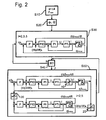
- Fig. 2 illustrates a corresponding regulation, which may be implemented for example in the arranged in a control cabinet 4 robot controller.
- a first step S10 preferably in advance, the Cartesian straight line s + ⁇ k in the working space, along which the robot is to be yielding, and control parameters, for example, a maximum force F max , from which the robot is to move, are specified.
- a leading axis in this case the third axis selected.
- the robot 1 moves with a pure position control of all axes 2, 3, 5 its starting pose.
- the third axis is compliant regulated.
- a desired current limit 10 is indicated in step S50.
- the control returns to a pure position control for all axes (S40: "N").
- a desired-actual adjustment of the axle positions is preferably carried out.
- this axis can, for example, be considered by an optimizer which takes the controllability and observability as quality criteria into account Axis, determined as a guide axis and the line of action according to (7) are given.
Landscapes
- Engineering & Computer Science (AREA)
- Mechanical Engineering (AREA)
- Robotics (AREA)
- Manipulator (AREA)
- Resistance Welding (AREA)
Description
Die vorliegende Erfindung betrifft ein Verfahren und eine Vorrichtung zur Regelung eines mehrachsigen Manipulators, insbesondere eines Roboters.The present invention relates to a method and a device for controlling a multi-axis manipulator, in particular a robot.
Heutige Industrieroboter sind überwiegend positionsgeregelt. Hierzu werden in einem Interpolator Soll-Gelenkstellungen generiert und durch Einzelgelenkregler in den einzelnen Antrieben des Roboters angefahren. Wird eine Soll-Position jedoch, beispielsweise aufgrund eines Hindernisses oder einer ungenauen Umweltmodellierung bei der Bahnplanung, nicht erreicht, erhöht eine reine Positionsregelung die Antriebskräfte so lange, bis entweder Stellgrößenbeschränkungen überschritten werden, was zum Abschalten der Steuerung führt, oder der Roboter die Soll-Position gewaltsam anfährt und dabei gegebenenfalls ein Hindernis, ein Bauteil, ein Werkzeug oder sich selbst beschädigt.Today's industrial robots are predominantly position-controlled. For this purpose, nominal joint positions are generated in an interpolator and approached by individual joint regulators in the individual drives of the robot. However, if a desired position is not achieved, for example due to an obstacle or inaccurate environmental modeling in the path planning, a pure position control increases the drive forces until either manipulated variable limitations are exceeded, which results in the control being switched off, or the robot exceeds the set point. Forcefully violates the position and possibly an obstacle, a component, a tool or damage itself.
Ein anschauliches Beispiel ist das Punktschweißen mit einer Schweißzange: die Schweißelektroden sollen an vorgegebenen Stellen eines Bauteils mit einer vorgegebenen Anpresskraft an dieses angedrückt werden. Liegt das Bauteil jedoch nicht in der bei der Planung der Schweißpose zugrundegelegten Position, sondern ist beispielsweise in Schließrichtung der Schweißzange verschoben, würde ein rein positionsgeregelter Roboter die Schweißelektroden gewaltsam in die vorgegebenen Positionen drücken und dabei das Bauteil und die eine Elektrode beschädigen, während die andere gegebenenfalls keinen Kontakt mit dem Bauteil hat. Selbst wenn es nicht zur Beschädigung kommt, würden dem Schweißprozess nicht zuträgliche Kräfte auftreten, die die Qualität des Schweisspunktes bis zum Versagen vermindern könnte.An illustrative example is the spot welding with a welding gun: the welding electrodes are to be pressed at predetermined points of a component with a predetermined contact pressure on this. However, if the component is not in the position assumed in the planning of the welding pose, but is displaced, for example, in the closing direction of the welding gun, a purely position-controlled robot would forcibly push the welding electrodes in the predetermined positions, thereby damaging the component and the one electrode, while the other possibly has no contact with the component. Even if it does not damage, the welding process would incur unsuitable forces that could reduce the quality of the weld to failure.
Um solche Probleme zu lösen, ist es bekannt, gezielte passive Nachgiebigkeiten in der Roboterstruktur vorzusehen, beispielsweise durch ein sogenanntes "Remote Center of Compliance". Aufgrund der aufgabenspezifischen Steifigkeits- und Nachgiebigkeitsrichtungen ist dies jedoch nicht für unterschiedliche Anwendungsfälle einsetzbar. Auch eine aktiv steuerbare Werkzeuganbindung, etwa eine schwimmend gelagerte Schweißzange, die mittels Druckluft oder Servomotoren in verschiedene Ausgleichslagen justiert werden kann, muss an den jeweiligen Anwendungsfall angepasst werden und erfordert ebenso wie die passive Nachgiebigkeit zusätzlichen gerätetechnischen Aufwand.In order to solve such problems, it is known to provide targeted passive compliances in the robot structure, for example by a so-called "remote center of compliance". Due to the task-specific stiffness and compliance directions, however, this can not be used for different applications. Also an actively controllable tool connection, such as a floating welding tongs, by means of compressed air or servo motors in different Adjustment levels can be adjusted must be adapted to the particular application and requires as well as the passive compliance additional equipment expense.
In der Forschung werden daher seit langem Kraft-Regelungen untersucht, wobei vorliegend auch antiparallele Kräftepaare, i.e. Drehmomente, verallgemeinernd als Kräfte bezeichnet werden, unter einer Kraft-Regelung als insbesondere auch eine sogenannte Kraft-Momenten-Regelung ("KMR") verstanden wird. Ein als "FTCtrl" ("force Roque control") industriell umgesetztes Konzept ist dabei die Aufspaltung in positions- und kraftgeregelte Teilräume durch eine Selektionsmatrix, ein anderes die parallele Positions- und Kraftregelung mit Überlagerung der jeweiligen Stellgrößen, ein weiteres die Impedanzregelung, bei der Positionen und Kräfte über Kraftgesetze, insbesondere Feder-Dämpfer-Masse-Modelle verknüpft werden. Einen Überblick gibt beipielsweise
Die Umsetzung dieser Ansätze in der Praxis begegnet jedoch regelmäßig Schwierigkeiten. Beispielsweise erfordert eine Kraft-Regelung im kartesischen Raum, um eine Nachgiebigkeit längs einer kartesischen Richtung darzustellen, in obigem Anwendungsfall etwa längs der Schließrichtung der Schweißzange, einen hohen Rechenaufwand mit entsprechend trägem Regelverhalten. Auf der anderen Seite ist es bei der Kraftregelung aller Achsen problematisch, den jeweiligen Anteil der auf den Roboter wirkenden Kräfte aus den Motorströmen zu ermitteln, da die Kräfte aufgrund von Getriebeübersetzungen, Reibung und Rauschen nur ungenau rekonstruiert werden können.However, the implementation of these approaches in practice regularly encounters difficulties. For example, requires a force control in Cartesian space to represent a compliance along a Cartesian direction, in the above application, for example along the closing direction of the welding gun, a high computational effort with correspondingly sluggish control behavior. On the other hand, it is problematic in the force control of all axes to determine the respective proportion of the forces acting on the robot forces from the motor currents, since the forces can only be reconstructed inaccurate due to gear ratios, friction and noise.
Die
Die
Der Artikel "
Aufgabe der vorliegenden Erfindung ist es daher, das Verhalten von Manipulatoren in der Praxis zu verbessern.The object of the present invention is therefore to improve the behavior of manipulators in practice.
Diese Aufgabe wird durch ein Verfahren mit den Merkmalen des Anspruchs 1 gelöst. Anspruch 13 stellt eine Steuervorrichtung, Anspruch 14 bzw. 15 ein Computerprogramm bzw. ein Computerprogrammprodukt, insbesondere einen Datenträger oder ein Speichermedium, zur Durchführung eines Verfahrens nach Anspruch 1 unter Schutz. Die Unteransprüche betreffen vorteilhafte Weiterbildungen.This object is achieved by a method having the features of
Die vorliegende Erfindung basiert auf folgender Überlegung: eine nachgebende Bewegung im kartesischen bzw. Arbeitsraum entspricht einer Bewegung in einer oder mehreren Bewegungsachsen, beispielsweise Drehgelenken oder Linearachsen, des Manipulators. Wenigstens eine dieser Achsen wird als Führungsachse bestimmt und nachgiebig geregelt. Weitere Achsen, vorzugsweise alle übrigen Achsen, werden steif geregelt, wobei jedoch ein Soll-Wert auf Basis eines Ist-Wertes der Führungsachse(n) bestimmt wird. Die nachgebende Bewegung im kartesischen Raum wird sozusagen über die führende(n) Achse(n) parametrisiert. Dann kann einerseits die Nachgiebigkeit durch die nachgiebige Regelung dieser Führungsachse(n) dargestellt und andererseits die gewünschte nachgebende Bewegung im kartesischen Raum durch die steifen Regelungen der weiteren Achsen sichergestellt werden, die der nachgebenden führenden Achse folgen.The present invention is based on the following consideration: a yielding movement in the Cartesian or working space corresponds to a movement in one or more axes of motion, for example pivot joints or linear axes, of the manipulator. At least one of these axes is determined as a guide axis and compliant regulated. Other axes, preferably all other axes, are rigidly controlled, but a desired value is determined on the basis of an actual value of the guide axis (s). The yielding motion in Cartesian space is parametrized, so to speak, over the leading axis (s). Then, on the one hand, the compliance can be represented by the compliant control of this guide axis (s) and, on the other hand, the desired yielding movement in the Cartesian space can be ensured by the rigid controls of the further axes following the yielding leading axis.
Vorteilhaft kann das erfindungsgemäße Konzept die Verwendung einfacher, robuster, effizienter Regler für die Führungs- und weiteren Achsen ermöglichen und so gegenüber komplizierteren theoretischen Ansätzen zuverlässig und einfach umgesetzt werden.Advantageously, the concept according to the invention can enable the use of simple, robust, efficient controllers for the guide and further axes and thus be reliably and simply implemented in comparison to more complicated theoretical approaches.
Unter einer nachgiebigen Regelung wird vorliegend insbesondere eine Regelung verstanden, die unter einer Kraft, beispielsweise einer Führungskraft oder einer Kontaktkraft beim Auftreffen auf ein Hindernis, eine Bewegung, insbesondere ein Ausweichen bewirkt. Dieses Ausweichen erfolgt vorzugsweise in Abhängigkeit von Größe und/oder Richtung der Kraft. Die nachgiebige Regelung ist vorzugsweise als Einzelgelenkregelung der jeweiligen Führungsachse ausgebildet.In the present case, compliant control means, in particular, a regulation which causes a movement, in particular an evasion, under a force, for example a guiding force or a contact force when hitting an obstacle. This evasion preferably takes place as a function of the size and / or direction of the force. The compliant control is preferably designed as a single-joint control of the respective guide axis.
Insbesondere kann eine nachgiebige Regelung als Kraftregelung ausgebildet sein. Eine einwirkende Kraft kann hierzu beispielsweise direkt mittels eines Kraft- bzw. Kraft-Momenten-Sensors, vorzugsweise an einem Werkzeugflansch des Manipulators erfasst werden. Zusätzlich oder alternativ kann sie indirekt auf Basis von Deformationen des Manipulators, beispielsweise Biegungen seiner Glieder erfasst werden. Zusätzlich oder alternativ kann sie auf Basis einer Reaktionskraft in einem Antrieb des Manipulators erfasst werden, beispielsweise mittels eines dort angeordneten Kraft- bzw. Kraft-Momenten-Sensors. Die Reaktionskraft kann auch auf Basis der Kräfte ermittelt werden, die der Antrieb zusätzlich zu den Kräften aufbringen muss, die bei einer kontakt- bzw. kräftefreien Bahn auftreten, beispielsweise zusätzlich zu statischen Halte- oder dynamischen Kreisel- und Beschleunigungskräften. Solche Kräfte können insbesondere auf Basis eines Stromwertes eines Antriebselektromotors ermittelt werden. Denn die zur Bewegungsregelung aufgebrachten Motorströme sind, bereinigt um Gravitations-, Trägheits- und Reibungseffekte, im Wesentlichen linear zu den Reaktionskräften in den einzelnen Achsen. Dabei sei nochmals darauf hingewiesen, dass vorliegend auch ein Drehmoment verallgemeinernd als Kraft bezeichnet wird.In particular, a compliant control can be designed as force control. An acting force can be detected for this purpose, for example, directly by means of a force or moment-force sensor, preferably on a tool flange of the manipulator. Additionally or alternatively, it may be detected indirectly based on deformations of the manipulator, such as bends of its members. Additionally or alternatively, it can be detected based on a reaction force in a drive of the manipulator, for example by means of a there arranged force or force-moment sensor. The reaction force can also be determined based on the forces that the drive must apply in addition to the forces encountered in a non-contact or force-free path, for example, in addition to static holding or dynamic gyro and acceleration forces. Such forces can be determined in particular on the basis of a current value of a drive electric motor. Because the motor currents applied to the motion control are, adjusted for gravitational, inertial and friction effects, substantially linear to the reaction forces in the individual axes. It should again be noted that in the present case, a torque is generally referred to as a force.
Die nachgiebige Regelung kann als indirekte Kraftregelung ausgebildet sein, insbesondere als Impedanzregelung. Gleichermaßen kann sie auch als direkte Kraftregelung ausgebildet sein, insbesondere als parallele Kraft- und Positionsregelung, bei der sowohl Abweichungen zwischen Soll- und Ist-Kräften als auch zwischen Soll- und Ist-Positionen berücksichtigt und beispielsweise entsprechende Stellgrößen superponiert werden.The compliant control can be designed as an indirect force control, in particular as an impedance control. Likewise, it can also be designed as a direct force control, in particular as a parallel force and position control, in which both deviations between desired and actual forces and between desired and actual positions taken into account and, for example, corresponding control variables are superposed.
Eine einfache Möglichkeit einer Kraftregelung besteht in einer Limitierung der Antriebskräfte der Führungsachse. Diese wird hierzu grundsätzlich positionsgeregelt, wobei ihre Antriebskraft, beispielsweise durch Begrenzung eines maximalen Soll-Motorstroms in einem Stromregelkreis eines Kaskadenreglers, jedoch auch bei größeren Soll-Ist-Abweichungen einen vorgegebenen Grenzwert nicht übersteigen kann. Solange eine auf diese Weise kraftgeregelte Achse einen Widerstand erfährt, der den vorgegebenen Grenzwert nicht übersteigt, versucht sie, ihre Soll-Position anzufahren. Übersteigt der Widerstand, beispielsweise aufgrund einer Kollision mit einem Hindernis, diesen Grenzwert, lässt sich die Achse verschieben und setzt dem nur eine Kraft entsprechend des Grenzwertes entgegen, sie ist somit nachgiebig geregelt.A simple possibility of a force control consists in a limitation of the driving forces of the guide axis. This is basically position-controlled, wherein its driving force, for example by limiting a maximum target motor current in a current control loop of a cascade controller, but also with larger target-actual deviations can not exceed a predetermined limit. As long as a force-controlled axle in this way experiences a resistance which does not exceed the predetermined limit, it tries to approach its desired position. If the resistance, for example due to a collision with an obstacle, exceeds this limit value, the axis can be displaced and counteracts only a force corresponding to the limit value, and is thus flexibly regulated.
Entsprechend wird unter einer steifen Regelung vorliegend insbesondere eine Regelung verstanden, die im Wesentlichen unabhängig von entgegenwirkenden Kräften eine vorgegebene Soll-Position anfährt bzw. unter einer Kraft, beispielsweise einer Führungskraft oder einer Kontaktkraft beim Auftreffen auf ein Hindernis, möglichst keine ausweichende Bewegung bewirkt. Dabei können natürlich Obergrenzen für die hierzu erforderlichen Stellkräfte berücksichtigt werden, um Beschädigungen zu verhindern. Die steife Regelung ist vorzugsweise als Einzelgelenkregelung der jeweiligen weiteren Achse ausgebildet.Correspondingly, a stiff control in the present case is understood to mean, in particular, a control which essentially approaches a predetermined desired position independent of counteracting forces or, if possible, causes no evasive movement under a force, for example a guiding force or a contact force when hitting an obstacle. It can, of course Upper limits for the required adjusting forces are taken into account in order to prevent damage. The stiff control is preferably designed as a single joint control of the respective other axis.
Insbesondere kann eine steife Regelung als (reine) Positionsregelung ausgebildet sein. Unter einer Positions- bzw. Lageregelung wird dabei insbesondere auch eine Regelung verstanden, in der, beispielsweise in Form einer Kaskadenregelung, vorzugsweise mit Geschwindigkeits- und/oder Beschleunigungsvorsteuerung, eine Stellgröße, beispielsweise ein Motorstrom, auf Basis der Differenz zwischen Soll- und Ist-Positionen, deren Integralen und/oder zeitlichen Ableitungen bestimmt wird, beispielsweise eine ein- oder mehrfache Proportional(P)-, Differential(D)- und/oder Integral(I)-Regelung (P, PD, Pl, PID).In particular, a stiff control can be designed as (pure) position control. A position or position control is understood to mean, in particular, a regulation in which, for example in the form of a cascade control, preferably with speed and / or acceleration precontrol, a manipulated variable, for example a motor current, based on the difference between desired and actual Positions whose integrals and / or time derivatives are determined, for example, a single or multiple proportional (P), differential (D) and / or integral (I) control (P, PD, Pl, PID).
In einer bevorzugten Ausführung wird eine Kraft, der der Manipulator nachgiebig ausweichen soll, und/oder eine Wirkungslinie, längs der der Manipulator nachgiebig ausweichen soll, im kartesischen bzw. Arbeitsraum, vorzugsweise vorab, vorgegeben, beispielsweise durch entsprechende Vektoren in einem raumfesten Inertialsystem.In a preferred embodiment, a force which the manipulator is to move resiliently, and / or a line of action along which the manipulator is to move resiliently, are predetermined in the Cartesian or working space, preferably in advance, for example by appropriate vectors in a space-fixed inertial system.
Die vorgegebene Kraft kann beispielsweise eine Kontaktkraft sein, die der Manipulator längs der Wirkungslinie ausüben soll, etwa eine Anpresskraft einer Schweißzange längs ihrer Schließrichtung, und bei deren Überschreitung er längs der Wirkungslinie ausweichen soll.The predetermined force may be, for example, a contact force that the manipulator is to exert along the line of action, such as a contact force of a welding gun along its closing direction, and if exceeded, it should dodge along the line of action.
Eine vorgegebene Wirkungslinie kann beispielsweise eine Folge von Lagen und Orientierungen des TCPs sein. Sie kann dann zum Beispiel durch einen parametrisierten sechsdimensionalen Vektor mit drei Lage- und drei Winkelkoordinaten im kartesischen Raum vorgegeben werden. Gleichermaßen sind auch Wirkungslinien möglich, die beispielsweise nur die Lagen oder nur die Orientierung des TCPs definieren und dementsprechend durch einen parametrisierten dreidimensionalen Vektor vorgegeben werden können. Auf der anderen Seite ist auch die Vorgabe einer komplexeren räumlichen Nachgiebigkeit, etwa längs einer Ebene oder einer anderen Hyperfläche oder innerhalb eines Hyperraums im Raum der Lagen und/oder Orientierungen oder dem Konfigurationsraum der Gelenkkoordinaten, möglich. All diese Geraden, Kurven, Flächen, Hyperflächen und -räume werden nachfolgend zur Vereinfachung verallgemeinernd als Wirkungslinien bezeichnet. Durch die Vorgabe einer Wirkungslinie im Sinne der vorliegenden Erfindung kann also beispielsweise eine Eben im kartesischen Raum, in der der TCP des Manipulators mit oder ohne Beibehaltung der Orientierung nachgiebig ausweichen soll, oder eine Kugel, innerhalb der der TCP bei einem nachgiebigen Ausweichen bleiben soll, vorgegeben werden.For example, a given line of action may be a sequence of layers and orientations of the TCP. It can then be specified, for example, by a parameterized six-dimensional vector with three positional and three angular coordinates in Cartesian space. Likewise, lines of action are also possible which, for example, only define the positions or only the orientation of the TCP and can accordingly be specified by a parameterized three-dimensional vector. On the other hand, it is also possible to specify a more complex spatial compliance, for example along a plane or another hypersurface or within a hyperspace in the space of the layers and / or orientations or the configuration space of the joint coordinates. All of these lines, curves, surfaces, hypersurfaces, and spaces are referred to in general as simplifying lines of action. By specifying a line of action in the sense of the present invention, for example, a plane in Cartesian space, in which the TCP of the manipulator should yield yieldingly with or without maintaining the orientation, or a sphere within which the TCP should remain at a yielding yield, be specified.
Auf Basis einer Steuerbarkeit längs einer solchen Wirkungslinie und/oder auf Basis einer Beobachtbarkeit dieser Kraft können eine oder mehrere Bewegungsachsen des Manipulators als Führungsachse(n) bestimmt werden. Wie einleitend erläutert, bewirkt eine Kraft bzw. Bewegung längs einer Wirkungslinie im kartesischen Raum entsprechende Kraftkomponenten bzw. Bewegungen in einzelnen Achsen des Manipulators. Die Größe diese Komponenten bzw. Bewegungen kann beispielsweise ein Maß für die Steuerbarkeit längs der Wirkungslinie bzw. die Beobachtbarkeit der Kraft darstellen. D.h., eine Kraft, die aufgrund der Kinematik des Manipulators, insbesondere der wirksamen Hebelarme, Getriebeübersetzungen etc., in einem Antrieb eine größere Komponente einprägt, ist in dieser Achse besser beobachtbar. Verfährt der Manipulator bei Bewegung eines Antriebs um eine größere Strecke längs der Wirkungslinie, ist diese Wirkungslinie durch diese Achse besser steuerbar. Wird eine Führungsachse daher unter Berücksichtigung der Steuer- und/oder Beobachtbarkeit, beispielsweise als gewichtete Summe oder Straffunktion, gewählt, kann eine Kraft, gegenüber der der Manipulator nachgeben soll, bzw. eine Wirkungslinie, längs der der Manipulator nachgeben soll, mit dieser Führungsachse besonders gut parametrisiert werden.On the basis of a controllability along such an action line and / or on the basis of an observability of this force, one or more movement axes of the manipulator can be determined as a guide axis (s). As explained in the introduction, a force or movement along a line of action in the Cartesian space causes corresponding force components or movements in individual axes of the manipulator. The size of these components or movements, for example, represent a measure of the controllability along the line of action or the observability of the force. In other words, a force which, due to the kinematics of the manipulator, in particular the effective lever arms, gear ratios, etc., impresses a larger component in a drive is easier to observe in this axis. If, during movement of a drive, the manipulator travels a greater distance along the line of action, this line of action can be better controlled by this axis. If, therefore, a guide axis is selected taking into account the controllability and / or observability, for example as a weighted sum or puncture function, a force against which the manipulator is to yield or a line of action along which the manipulator is to yield can be particularly useful with this guide axis be well parameterized.
Da sich die Kraftkomponenten bzw. Bewegungen und damit die Steuer- bzw. Beobachtbarkeit je nach aktueller Pose des Manipulators ändern können, ist in einer bevorzugten Ausführung vorgesehen, abhängig von einer Pose des Manipulators unterschiedliche Führungsachsen zu wählen.Since the force components or movements and thus the control or observability can change depending on the current pose of the manipulator, it is provided in a preferred embodiment to select different guide axes depending on a pose of the manipulator.
Insbesondere, um die Kraftkomponenten bzw. Bewegungen und damit die Steuer- bzw. Beobachtbarkeit beurteilen zu können, wird in einer bevorzugten Ausführung die Kraft und/oder die Wirkungslinie aus dem kartesischen bzw. Arbeitsraum in den Gelenkraum transformiert, der durch die Wertebereiche der einzelnen Achsen definiert ist.In particular, in order to be able to assess the force components or movements and thus the controllability or observability, in a preferred embodiment, the force and / or the line of action is transformed from the Cartesian or working space into the joint space, which passes through the value ranges of the individual axes is defined.
Diese Transformation ist ebenfalls von der Pose des Manipulators abhängig. Jedenfalls im Bereich kleiner Änderungen von einer Referenzpose kann die Transformation durch eine lineare TAYLOR-Entwicklung angenähert werden. Da eine solche lineare Transformation rechentechnisch effizient umzusetzen ist, wird in einer bevorzugten Ausführung die Transformation lokal, insbesondere für eine bestimmte Pose des Manipulators, linearisiert. Da eine solche Linearisierung in der Regel nur lokal gut approximiert, kann sie für verschiedene Posen durchgeführt werden. Durch Umschalten oder Interpolation der entsprechenden linearen Transformationen kann die Transformation auch für größere Arbeitsbereiche des Manipulators adaptiert werden.This transformation is also dependent on the pose of the manipulator. In any case, in the area of small changes of a reference pose, the transformation can be approximated by a linear TAYLOR development. Since such a linear transformation is to be implemented computationally efficiently, in a preferred embodiment the transformation is linearized locally, in particular for a specific pose of the manipulator. Since such a linearization usually approximates only locally well, it can be performed for different poses. By switching or interpolating the corresponding linear transformations, the transformation can also be adapted for larger working ranges of the manipulator.
In einer bevorzugten Ausführung hängt ein Soll-Wert der weiteren Achse linear von einem Ist-Wert der Führungsachse(n) ab. Insbesondere bei einer linearisierten Transformation wird eine kartesische Wirkungslinie in eine lineare Funktion in den Gelenkkordinaten transformiert, so dass eine Parametrisierung mit der Gelenkkordinate der Führungsachse(n) auf lineare Funktionen in den weiteren Achsen führt. Gleichermaßen können jedoch auch nichtlineare Funktionen zwischen Ist-Werten der Führungsachse(n) und Soll-Werten der weiteren Achsen gewählt werden. Diese können beispielsweise tabellarisch abgespeichert werden, wobei zwischen Tabellenwerten interpoliert werden kann. Ebenso eignen sich, ggf. durch die durch die Applikation vorgegebene Form der Wirkungslinie besonders begünstige Darstellungen in geeigneten endlichdimensionalen Funktionenräumen wie Polynome, Splines, endliche Fourier-Reihen, etc.In a preferred embodiment, a desired value of the further axis depends linearly on an actual value of the guide axis (s). In particular, in the case of a linearized transformation, a Cartesian line of action is transformed into a linear function in the joint coordinates, so that a parameterization with the joint coordinate of the guide axis (s) leads to linear functions in the further axes. Likewise, however, nonlinear functions can also be selected between actual values of the guide axis (s) and desired values of the further axes. These can be stored, for example, in tabular form, whereby it is possible to interpolate between table values. Equally suitable, if appropriate by the form of the action line given by the application, are particularly favorable representations in suitable finite-dimensional function spaces such as polynomials, splines, finite Fourier series, etc.
In einer bevorzugten Ausführung werden zunächst mehrere mögliche Wirkungslinien bestimmt. Beispielsweise können neben einer Geraden oder Ebene im kartesischen Raum, längs der der TCP unter Beibehaltung seiner Orientierung nachgeben soll, kollineare Geraden bzw. koplanare Ebenen, längs derer der TCP unter Änderung seiner Orientierung nachgeben soll, als weitere mögliche Wirkungslinien bestimmt werden. Dann kann eine dieser möglichen Wirkungslinien, vorzugsweise auf Basis einer Steuerbarkeit längs der Wirkungslinie und/oder auf Basis einer Beobachtbarkeit der Kraft, ausgewählt und als die Wirkungslinie vorgegeben werden, längs der der Manipulator nachgiebig ausweichen soll. Kann also beispielsweise eine Ausweichbewegung längs einer Geraden, bei der sich die Orientierung des TCPs ändert, in einer Achse besser gesteuert werden, wird in einer bevorzugten Ausführung, zum Beispiel durch einen Optimierer, diese Achse als Führungsachse gewählt.In a preferred embodiment, first several possible lines of action are determined. For example, in addition to a straight line or plane in Cartesian space along which the TCP is intended to yield while maintaining its orientation, collinear lines or coplanar planes along which the TCP is intended to yield by changing its orientation can be determined as further possible lines of action. Then one of these possible lines of action, preferably based on a controllability along the line of action and / or on the basis of an observability of the force, can be selected and given as the line of action along which the manipulator is to move yieldingly. So, for example, can an evasive movement along a straight line, in which the orientation of the TCPs changes, be better controlled in one axis, in a preferred embodiment, for example by an optimizer, this axis is selected as a guide axis.
Vorzugsweise entspricht die Anzahl der Führungsachsen der Anzahl der Freiheitsgrade der vorgegebenen Nachgiebigkeit bzw. der Dimension der Wirkungslinie, die diese Nachgiebigkeit beschreibt. Soll der TCP eines Manipulators beispielsweise unter Beibehaltung seiner Orientierung längs einer Geraden im kartesischen Raum nachgiebig sein, handelt es sich um eine eindimensionale Wirkungslinie, der TCP weist einen Freiheitsgrad auf. Dann kann eine Bewegungsachse als Führungsachse ausgewählt und die restlichen Achsen können mit dieser parametrisiert werden. Soll der TCP hingegen unter Beibehaltung seiner Orientierung längs einer Ebene im kartesischen Raum nachgiebig sein, handelt es sich um eine zweidimensionale Wirkungslinie bzw. Hyperfläche, der TCP weist zwei Freiheitsgrade auf. Dann können zwei Bewegungsachsen als Führungsachsen ausgewählt und die verbleibenden Achsen können mit diesen parametrisiert werden.The number of guide axes preferably corresponds to the number of degrees of freedom of the predetermined compliance or the dimension of the line of action which describes this compliance. If, for example, the TCP of a manipulator is to be yielding while maintaining its orientation along a straight line in Cartesian space, this is a one-dimensional line of action, the TCP has one degree of freedom. Then a motion axis can be selected as the guide axis and the remaining axes can be parameterized with it. On the other hand, if the TCP is to be yielding while maintaining its orientation along a plane in Cartesian space, then it is a two-dimensional line of action or hypersurface, the TCP has two degrees of freedom. Then two axes of motion can be selected as leading axes and the remaining axes can be parameterized with them.
Ein Manipulator soll in manchen Anwendungsfällen nur abschnittsweise nachgiebig sein. So soll beispielsweise ein Industrieroboter kontaktfreie Bahnen, zum Beispiel zum Anfahren einer Ausgangspose, steif und mit hoher Präzision ausführen, und sich erst bei Kontakt mit der Umgebung, beispielsweise durch Schließen einer Schweißzange, in einer vorgegebenen Richtung nachgiebig verhalten. Daher wird in einer bevorzugten Ausführung wahlweise zwischen einer nachgiebigen Regelung wenigstens einer Führungsachse und einer steifen Regelung aller Bewegungsachsen umgeschaltet.A manipulator should be compliant only partially in some applications. For example, an industrial robot is designed to perform non-contact webs, for example, to approach a starting pose, rigidly and with high precision, and only to yield in a given direction when in contact with the environment, for example by closing a welding gun. Therefore, in a preferred embodiment optionally switched between a compliant control of at least one guide axis and a rigid control of all axes of motion.
Weitere Vorteile und Merkmale ergeben sich aus den Unteransprüchen und den Ausführungsbeispielen. Hierzu zeigt, teilweise schematisiert:
- Fig. 1:
- einen Roboter mit einer Steuervorrichtung nach einer Ausführung der vorliegenden Erfindung; und
- Fig. 2:
- die Abarbeitung eines Verfahrens nach einer Ausführung der vorliegenden Erfindung durch die Steuervorrichtung nach
Fig. 1 .
- Fig. 1:
- a robot with a control device according to an embodiment of the present invention; and
- Fig. 2:
- the execution of a method according to an embodiment of the present invention by the control device according to
Fig. 1 ,

mit den Komponenten rx, ry des Ortsvektors r zum TCP sowie dem EULER-Winkel ϕ
um die z-Achse. Die Jacobimatrix lautet lokal in der in 
with the components r x , r y of the position vector r to the TCP and the EULER angle φ
around the z-axis. The Jacobian matrix is local to the in
Der Roboter 1 soll in der γ-Richtung des Inertialsystems y nachgiebig sein, so dass sich die Schweißzange 2 beim Anfahren der Bleche 3 mit den Schweißelektroden in dieser Richtung zentrieren kann. Hierzu soll der TCP des Roboters längs der kartesischen Geraden 
maximal eine Kraft F max 
aufbringen.The
maximum one force F max
muster.
Diese Gerade s + λ k und maximale Kontaktkraft F max können nach (2) bis (4) und den in der Robotik allgemein bekannten Identitäten Q = JT *F und J * dq = dx lokal um den Punkt s in den Raum der Gelenkkordinaten q = [q2, q3, q5]T transformiert werden: 
Eine Kraft F längs der Geraden s + λ k erzeugt im Gelenk 5 aufgrund des verschwindenden Hebelarmes kein Drehmoment (Qz=0), so dass die fünfte Achse zur Kraft-Momenten-Regelung aufgrund schlechter Beobachtbarkeit nicht geeignet ist. Auf der anderen Seite verfährt die zweite Achse nicht, so dass die dritte Achse bezüglich der Wirkungslinie s + λ k eine bessere Steuerbarkeit aufweist.A force F along the straight line s + λ k generates no torque (Q z = 0) in the joint 5 due to the vanishing lever arm, so that the fifth axis is not suitable for force-torque control due to poor observability. On the other hand, the second axis does not move so that the third axis has better controllability with respect to the line of action s + λ k .
Daher wird die dritte Achse als eine führende Achse ausgewählt und die kartesische Gerade, längs der der Roboter 1 nachgiebig sein soll, mit dem Gelenkwinkel q3 parametrisiert. Auf diese Weise wird einerseits eine ausreichend große Führungsgröße erreicht. Auf der anderen Seite kann die Kontaktkraft gut auf Basis des im Antriebsmotor der dritten Achse erzeugten Drehmomentes erfasst werden.Therefore, the third axis is selected as a leading axis and the Cartesian straight line along which the
Hat der Roboter 1 mit seinem TCP die in
Die anderen Achsen, im Ausführungsbeispiel insbesondere die zweite und fünfte Achse, werden hingegen steif bzw. positionsgeregelt. Hierzu kann beispielsweise ein Gelenkwinkel q2 bzw. q5 und/oder eine Gelenkwinkelgeschwindigkeit dq2/dt bzw. dq5/dt, zum Beispiel mittels Tachogeneratoren, Resolver oder inkrementale Drehgeber, erfasst, rückgeführt und in einer Positions-Geschwindigkeits-Strom-Kaskadenregelung einem Soll-Wert q2s bzw. q5s nachgeführt werden.The other axes, in the embodiment, in particular the second and fifth axis, however, are stiff or position-controlled. For this purpose, for example, a joint angle q2 or q5 and / or a joint angular velocity dq2 / dt or dq5 / dt, for example by means of tachogenerators, resolvers or incremental encoders detected, returned, and in a position-speed-current cascade control a target value q2 s or q5 s are tracked.
Erfindungsgemäß wird dieser Soll-Wert für die positionsgeregelte zweite und fünfte Achse auf Basis des Ist-Wertes q3mess der nachgiebig geregelten dritten Achse bestimmt. Nach (5) können die Soll-Wert q2s und q5s beispielsweise als 
vorgegeben werden.According to the invention this desired value for the position-controlled second and fifth axis on the basis of the actual value of the measured q3 resiliently regulated third axis is determined. According to (5), the setpoint values q2 s and q5 s can be described as, for example,
be specified.
Schließt nun der Roboter 1, ausgehend von der in
Aufgrund der nachgiebigen Regelung der dritten Achse kann der Roboter in dieser Richtung ausweichen. Denn sobald das aufgrund der Reaktionskraft F in der dritten Achse eingeprägte Drehmoment den zulässigen Wert ±x3 Fmax überschreitet, steigt der Sollstrom im Motorregler trotz Positionsabweichung nicht mehr weiter an und der Roboter 1 weicht unter der Reaktionskraft in seiner dritten Achse aus.Due to the compliant control of the third axis, the robot can dodge in this direction. For as soon as the torque impressed on the third axis due to the reaction force F exceeds the permissible value ± x3 F max , the setpoint current in the motor controller no longer increases despite positional deviation and the
Diese Ausweichbewegung, d.h. die gemessenen Ist-Werte des Gelenkwinkels q3mess, führt aufgrund ihrer steifen Positionsregelungen zu einer entsprechenden Nachführung in der zweiten und fünften Achse. Sie folgen der Ausweichbewegung der dritten Achse dabei derart, dass der TCP sich längs der kartesischen Geraden s + λ k , d.h. in Schließrichtung der Schweißzange 2 verschiebt. Auf diese Weise zentriert sich die Schweißzange 2 mittels einfacher, robuster und schneller Regler.This evasive movement, ie the measured actual values of the joint angle q3 mess , leads due to their stiff position controls to a corresponding tracking in the second and fifth axes. They follow the deflection movement of the third axis in such a way that the TCP shifts along the Cartesian straight line s + λ k , ie in the closing direction of the
Wie aus dem Ausführungsbeispiel klar wird, verschiebt sich der TCP bei einer linearen Abhängigkeit der Soll-Werte der positionsgeregelten Achsen vom Ist-Wert der führenden Achse nach (6) im Allgemeinen nur näherungsweise längs einer Geraden im kartesischen bzw. Arbeitsraum. Dies kann jedoch beim Anwendungsfall des Punktsweißens mit entsprechend kleinen Zustellwegen von in der Regel 1 bis 2 cm bereits ausreichend sein.As is clear from the embodiment, the TCP shifts in a linear dependence of the setpoint values of the position-controlled axes of the actual value of the leading axis after (6) generally only approximately along a straight line in the Cartesian or working space. However, this may already be sufficient in the case of application of spot whitening with correspondingly small delivery distances of usually 1 to 2 cm.
Gleichwohl kann das erfindungsgemäße Verfahren allgemein auch für größere Bahnen genutzt werden, indem beispielsweise die Linearisierung, insbesondere die Auswertung der Jacobimatrix gemäß (2), abschnittsweise bzw. für verschiedene Posen des Roboters 1 wiederholt und an die geänderte Kinematik angepasst wird. Dabei kann gegebenenfalls auch die führende Achse gewechselt werden. Eine weitere Möglichkeit für größere Bahnen ist, statt der Approximation der Wirkungslinie durch eine Gerade im Gelenkraum, die über die führende Achse parametriert wird (d.h. die im Ausführungsbeispiel gezeigte Linearisierung), die gewünschte Wirkungslinie im kartesischen Raum durch eine Approximation höherer Ordnung im Gelenkraum darzustellen, wobei wiederum vorzugsweise eine Darstellung gewählt werden sollte, in der die folgenden Achsen als Funktion der führenden Achse erscheinen.Nevertheless, the method according to the invention can generally also be used for larger paths, for example by repeating the linearization, in particular the evaluation of the Jacobian matrix according to (2), in sections or for different poses of the
In einem ersten Schritt S10 werden, vorzugsweise offline vorab, die kartesische Gerade s + λ k im Arbeitsraum, längs der der Roboter nachgiebig sein soll, sowie Regelparameter, beispielsweise eine Maximalkraft Fmax, ab der der Roboter ausweichen soll, vorgegeben.In a first step S10, preferably in advance, the Cartesian straight line s + λ k in the working space, along which the robot is to be yielding, and control parameters, for example, a maximum force F max , from which the robot is to move, are specified.
Aus diesen werden in einem Schritt S20, gegebenenfalls für mehrere Posen und vorzugsweise linearisiert, die zugehörigen Gelenkwinkel q k und Drehmomente Q ermittelt. Auf Basis der Beobachtbarkeit einer Kraft längs der kartesischen Geraden, i.e. der Größe des durch diese im Antriebsmotor eingeprägten Drehmomentes, und der Steuerbarkeit, i.e. der Größe des Verstellweges der jeweiligen Achse beim Verfahren längs der kartesischen Geraden, wird eine führende Achse, vorliegend die dritte Achse ausgewählt.From these, in a step S20, if appropriate for a plurality of poses and preferably linearized, the associated joint angle q k and torques Q are determined. Based on the observability of a force along the Cartesian line, ie the size of the impressed by this in the drive motor torque, and the controllability, ie the size of the displacement of the respective axis when moving along the Cartesian line, a leading axis, in this case the third axis selected.
Der Roboter 1 fährt mit einer reinen Positionsregelung aller Achsen 2, 3, 5 seine Startpose an. Hierzu ist in Schritt S30 eine Kaskadenregelung für die einzelnen Achsen i = 2, 3 und 5 mit einem Proportional-Positions-Regler, einer Geschwindigkeitsvorsteuerung, einem PID-Regler und einem Proportional-Integral-Motor- bzw. Stromregler angedeutet.The
Sobald der Roboter 1 seine Startpose angefahren hat, wird auf die erfindungsgemäße Regelung umgeschaltet (S40: "J").As soon as the
In dieser wird die dritte Achse nachgiebig geregelt. Hierzu ist in Schritt S50 eine Soll-Strombegrenzung 10 angedeutet. Die übrigen Achsen i = 2, 5 werden positionsgeregelt, wobei ihre Soll-Werte sich jedoch nicht mehr aus dem Interpolator der Robotersteuerung 4, sondern aus den Ist-Werten der dritten Achse ergeben, wie ebenfalls in Schritt S50 durch das Glied 20 angedeutet.In this, the third axis is compliant regulated. For this purpose, a desired
Sobald der Punktschweißvorgang beendet ist, kehrt die Regelung in eine reine Positionsregelung für alle Achsen zurück (S40: "N"). Dabei wird vorzugsweise ein Soll-Ist-Abgleich der Achspositionen durchgeführt.Once the spot welding process is completed, the control returns to a pure position control for all axes (S40: "N"). In this case, a desired-actual adjustment of the axle positions is preferably carried out.
Im obigen Ausführungsbeispiel behält der TCP bei einem Nachgeben längs der Gerade s + λ k lokal seine Orientierung bei (ϕ = q2 + q3 + q5 = 0). Gibt man diese Forderung auf, kann aufgrund des Fortfalls der dritten Zeile in (2) eine andere Wirkungslinie, beispielsweise durch 
parametrisiert werden. Weist eine Achse diesbezüglich eine bessere Steuer- und/oder Beobachtbarkeit auf als die dritte Achse bezüglich (6), kann, zum Beispiel durch einen Optimierer, der die Steuer- und Beobachtbarkeit als Gütekriterien berücksichtigt, diese Achse, in (7) beispielsweise die zweite Achse, als Führungsachse bestimmt und die Wirkungslinie gemäß (7) vorgegeben werden.In the above embodiment, the TCP retains its local orientation when yielding along the straight line s + λ k (φ = q2 + q3 + q5 = 0). If one gives up this requirement, due to the omission of the third line in (2) another line of action, for example by
be parameterized. If an axis has a better controllability and / or observability in this respect than the third axis with respect to (6), this axis can, for example, be considered by an optimizer which takes the controllability and observability as quality criteria into account Axis, determined as a guide axis and the line of action according to (7) are given.
- 11
- Roboterrobot
- 22
- Schweißzangewelding gun
- 33
- Blechsheet
- 44
- Steuerschrankcontrol cabinet
- q1,...q6q1 ... q6
- Gelenkwinkeljoint angle
- II
- Inertialsysteminertial
- TCPTCP
- Tool Center Point (Werkzeugreferenzsystem)Tool Center Point (tool reference system)
- x1,...y6x1, ... y6
- Achsabständewheelbases
Claims (13)
- A method for controlling of a multi-axis manipulator, in particular a robot (1), comprising the steps:compliant control (S50) of at least one leading axis; andstiff control (S50) of at least one further axis;characterized in that,
a demand-value (q2s, q5s) of said at least one further axis is determined on the basis of an actual value (q3mess) of the leading axis, and a force (Fmax), to which the manipulator is to dodge compliantly and/or a line of action (s+ λ·k), lengthwise to which the manipulator is to dodge compliantly, is determined, in particular in the working space; and selectively switching between a compliant and a stiff control (S40); wherein the line of action can be an order of locations and orientations of the TCPs, a straight line, a curve, a surface, a hyper-surface or a hyper-space. - A method according to claim 1, characterized in that a plurality of possible lines of action are determined and one of these is selected, in particular on the basis of a controllability lengthwise of a line of action and/or on the basis of an observability of a force, and is provided as line of action (s+ λ·k), lengthwise that the manipulator is to dodge compliantly.
- A method according to one of the preceding claims, characterized in that at least one motion axis of the manipulator is determined as leading axis on the basis of a controllability lengthwise of the provided line of action and/or on the basis of an observability of the force.
- A method according to one of the preceding claims 1 to 3, characterized in that the force and/or the line of action is transformed to joint spaces (20).
- A method according to claim 4, characterized in that the transformation is linearized locally and/or adapted.
- A method according to one of the preceding claims, characterized in that a compliant control is formed as force control; and/or that a stiff control is formed as position control.
- A method according to claim 6, characterized in that a compliant control is formed as indirect force control, in particular as impedance control, or is formed as direct force control, in particular as parallel force and position control.
- A method according to one of the preceding claims 6 to 7, characterized in that for the force control a force exerted on the manipulator is determined on the basis of a reaction force in a drive of at least one leading axis, in particular on the basis of a current value of an electrical drive motor.
- A method according to one of the preceding claims, characterized in that a demand-value of a further axis is dependent linearily or non-linearily on an actual value of at least one leading axis ((q2s = 0·q3mess, q5s = -q3mess); (q3s = - q2mess; q5s = (y2/y6)q2mess)).
- A method according to one of the preceding claims, characterized in that, different leading axes are selected dependent on a pose of the manipulator.
- A control apparatus (4) for a manipulator, in particular a robot (1), comprising:a compliant controller for at least one leading axis; anda stiff controller for at least one further axis;characterized in that,
the controller is arranged for carrying out a method according to one of the preceding claims. - A computer program that performs a method according to one of the claims 1 to 10, if it runs in a control apparatus according to claim 11.
- A computer program product with program code that is saved on a machine-readable carrier and comprises a computer program according to claim 12.
Applications Claiming Priority (3)
| Application Number | Priority Date | Filing Date | Title |
|---|---|---|---|
| DE200910018403 DE102009018403A1 (en) | 2009-04-22 | 2009-04-22 | Method for controlling a welding robot, for welding with a welding tong and a force detecting device for detecting reaction forces on the welding tong, comprises determining a sum of reaction forces on the welding tong |
| DE200910049327 DE102009049327A1 (en) | 2009-10-14 | 2009-10-14 | Method for controlling a welding robot, for welding with a welding tong and a force detecting device for detecting reaction forces on the welding tong, comprises determining a sum of reaction forces on the welding tong |
| DE102009049329A DE102009049329A1 (en) | 2009-10-14 | 2009-10-14 | Method for controlling a welding robot, for welding with a welding tong and a force detecting device for detecting reaction forces on the welding tong, comprises determining a sum of reaction forces on the welding tong |
Publications (3)
| Publication Number | Publication Date |
|---|---|
| EP2243602A2 EP2243602A2 (en) | 2010-10-27 |
| EP2243602A3 EP2243602A3 (en) | 2012-05-09 |
| EP2243602B1 true EP2243602B1 (en) | 2013-05-15 |
Family
ID=42320679
Family Applications (3)
| Application Number | Title | Priority Date | Filing Date |
|---|---|---|---|
| EP10003621.9A Active EP2243586B1 (en) | 2009-04-22 | 2010-03-31 | Method and device for controlling a positioning device for welding |
| EP10003623.5A Active EP2243602B1 (en) | 2009-04-22 | 2010-03-31 | Method and device for controlling a manipulator |
| EP10003620.1A Active EP2243585B1 (en) | 2009-04-22 | 2010-03-31 | Method and device for controlling a positioning device for welding |
Family Applications Before (1)
| Application Number | Title | Priority Date | Filing Date |
|---|---|---|---|
| EP10003621.9A Active EP2243586B1 (en) | 2009-04-22 | 2010-03-31 | Method and device for controlling a positioning device for welding |
Family Applications After (1)
| Application Number | Title | Priority Date | Filing Date |
|---|---|---|---|
| EP10003620.1A Active EP2243585B1 (en) | 2009-04-22 | 2010-03-31 | Method and device for controlling a positioning device for welding |
Country Status (6)
| Country | Link |
|---|---|
| US (3) | US8395081B2 (en) |
| EP (3) | EP2243586B1 (en) |
| JP (1) | JP5971887B2 (en) |
| KR (1) | KR101683289B1 (en) |
| CN (1) | CN101890715B (en) |
| ES (1) | ES2424244T3 (en) |
Cited By (1)
| Publication number | Priority date | Publication date | Assignee | Title |
|---|---|---|---|---|
| DE102016105084A1 (en) | 2016-03-18 | 2017-09-21 | Dr. Ing. H.C. F. Porsche Aktiengesellschaft | Joining device and method for operating a joining device |
Families Citing this family (33)
| Publication number | Priority date | Publication date | Assignee | Title |
|---|---|---|---|---|
| ES2424244T3 (en) * | 2009-04-22 | 2013-09-30 | Kuka Roboter Gmbh | Procedure and device to regulate a manipulator |
| JP5572046B2 (en) * | 2010-09-13 | 2014-08-13 | 株式会社神戸製鋼所 | Dissimilar material joining method |
| US20130054023A1 (en) * | 2011-08-30 | 2013-02-28 | 5D Robotics, Inc. | Asynchronous Data Stream Framework |
| DE102011087958A1 (en) * | 2011-12-08 | 2013-06-13 | Kuka Roboter Gmbh | welding robots |
| DE202011052430U1 (en) * | 2011-12-22 | 2013-03-25 | Kuka Systems Gmbh | Tool changing system |
| US20130197672A1 (en) * | 2012-01-26 | 2013-08-01 | Intuitive Surgical Operations, Inc. | Pass-Through Controller for Cascaded Proportional-Integral-Derivative Control Loops |
| US9144860B2 (en) * | 2012-03-29 | 2015-09-29 | Fanuc Robotics America Corporation | Robotic weld gun orientation normalization |
| DE202012101833U1 (en) * | 2012-05-18 | 2013-08-20 | Kuka Systems Gmbh | Multi-part tool |
| JP6111562B2 (en) * | 2012-08-31 | 2017-04-12 | セイコーエプソン株式会社 | robot |
| JP6250555B2 (en) * | 2012-12-18 | 2017-12-20 | 株式会社安川電機 | Seam welding equipment, seam welding method, robot controller, and robot control method |
| AU2015220546A1 (en) * | 2014-02-20 | 2016-06-09 | Mark Oleynik | Methods and systems for food preparation in a robotic cooking kitchen |
| JP5893666B2 (en) | 2014-04-14 | 2016-03-23 | ファナック株式会社 | Robot control device and robot system for robots that move according to force |
| JP6511626B2 (en) * | 2014-04-18 | 2019-05-15 | 株式会社安川電機 | Seam welding system, seam welding method and method of producing workpiece |
| JP5845311B2 (en) | 2014-04-30 | 2016-01-20 | ファナック株式会社 | Control device for flexible control of robots |
| CN104070525B (en) * | 2014-06-18 | 2016-02-03 | 大连大学 | For the method for space manipulator continuous trajectory tracking |
| DE102014222809B3 (en) * | 2014-11-07 | 2016-01-14 | Kuka Roboter Gmbh | Event-based redundancy angle configuration for articulated arm robots |
| KR101630405B1 (en) * | 2014-11-27 | 2016-06-15 | 한전원자력연료 주식회사 | Spot welding device for nuclear fuel skeleton and spot welding method using that |
| DE102015204599B3 (en) * | 2015-03-13 | 2016-08-11 | Kuka Roboter Gmbh | Method for controlling a manipulator for executing a work process |
| CN106200685B (en) * | 2015-05-04 | 2019-03-19 | 中国科学院沈阳自动化研究所 | The remote operating control algolithm of non-linear placement and speed |
| US9815198B2 (en) * | 2015-07-23 | 2017-11-14 | X Development Llc | System and method for determining a work offset |
| KR102312368B1 (en) * | 2015-08-04 | 2021-10-12 | 한국전기연구원 | System, method for controlling redundant robot, and a recording medium having computer readable program for executing the method |
| CN105729460B (en) * | 2016-04-20 | 2017-11-28 | 机器时代(北京)科技有限公司 | Flexible gearing and adjustable spring and energy storage component and lock uint and robot |
| DE102016004841B4 (en) * | 2016-04-24 | 2018-01-04 | Kastanienbaum GmbH | Method and device for determining a movement sequence for a robot |
| DE102017102621B3 (en) * | 2017-02-09 | 2018-05-09 | Franka Emika Gmbh | robot |
| DE102017121095A1 (en) * | 2017-09-12 | 2019-03-14 | Matuschek Meßtechnik GmbH | Method and device for measuring an electrode force of a welding gun |
| JP7148321B2 (en) * | 2018-08-20 | 2022-10-05 | ファナック株式会社 | Control device for articulated robot |
| CN109333530B (en) * | 2018-10-08 | 2020-05-26 | 浙江工业大学 | Six-joint mechanical arm contact force control method based on series elastic actuator |
| CN109732614A (en) * | 2019-03-19 | 2019-05-10 | 合肥工业大学 | The control design case method and device thereof and controller of SCARA robot based on restraining force |
| JP7015267B2 (en) * | 2019-03-29 | 2022-02-02 | ファナック株式会社 | Robot control device and robot system |
| CN110154022B (en) * | 2019-05-20 | 2020-10-30 | 南京航浦机械科技有限公司 | Directional stiffness model-based robot hole-making radial positioning correction method |
| CN112223302B (en) * | 2020-12-17 | 2021-02-26 | 国网瑞嘉(天津)智能机器人有限公司 | Rapid calibration method and device of live working robot based on multiple sensors |
| CN112549085B (en) * | 2021-02-25 | 2021-05-18 | 辽宁省医疗器械检验检测院 | Mechanical arm offset detection system and method based on visual compensation |
| CN113319876B (en) * | 2021-06-28 | 2023-02-03 | 北京邮电大学 | Multi-finger humanoid dexterous hand driven by fluid |
Family Cites Families (47)
| Publication number | Priority date | Publication date | Assignee | Title |
|---|---|---|---|---|
| IT1165233B (en) * | 1979-09-25 | 1987-04-22 | Fiat Ricerche | SIX DEGREE FREEDOM TRANSDUCER PARTICULARLY FOR ROBOTS |
| DE3018384A1 (en) * | 1980-05-14 | 1981-11-19 | Rossell Electronique S.A., Lausanne | METHOD FOR ATTACHING AT LEAST ONE ELECTRODE, FEEDING DEVICE AND RECEIVER FOR CARRYING OUT THIS METHOD, AND USE OF THE METHOD, THE FEEDING DEVICE AND / OR THE RECEIVER |
| FR2539346B1 (en) * | 1983-01-18 | 1990-12-07 | Mitsubishi Electric Corp | ARTICULATED AUTOMATIC MANIPULATOR DEVICE, PARTICULARLY FOR ARC WELDING |
| DE3503675A1 (en) * | 1985-02-04 | 1986-08-07 | L. & C. Steinmüller GmbH, 5270 Gummersbach | METHOD AND DEVICE FOR MECHANICALLY CONTROLLED FLAME CUTTING AND / OR JOINT WELDING WORKPIECES |
| JPS6356369A (en) * | 1986-08-27 | 1988-03-10 | Mitsubishi Electric Corp | Welding machine head |
| US4860215A (en) * | 1987-04-06 | 1989-08-22 | California Institute Of Technology | Method and apparatus for adaptive force and position control of manipulators |
| JPH0683976B2 (en) * | 1988-03-15 | 1994-10-26 | インターナシヨナル・ビジネス・マシーンズ・コーポレーシヨン | Compliance control method |
| JPH0832401B2 (en) * | 1988-09-08 | 1996-03-29 | 川崎重工業株式会社 | Industrial robot |
| JP2604929B2 (en) * | 1991-12-03 | 1997-04-30 | 山武ハネウエル株式会社 | Robot control device |
| DE4332807C2 (en) * | 1992-10-20 | 2002-07-18 | Schlattl Werner Bavaria Tech | Opto-electrical sensor |
| JPH06309040A (en) * | 1993-04-21 | 1994-11-04 | Daikin Ind Ltd | Controller for robot arm |
| US5504298A (en) * | 1993-06-04 | 1996-04-02 | Axis Usa, Inc. | Methods and apparatus for detecting electrode separation |
| JP3114440B2 (en) * | 1993-07-22 | 2000-12-04 | 日産自動車株式会社 | Spot welding equipment |
| JPH0760457A (en) * | 1993-08-26 | 1995-03-07 | Na Detsukusu:Kk | Resistance welding machine |
| DE19524486A1 (en) * | 1995-07-05 | 1997-01-09 | Schlattl Werner Bavaria Tech | Resistance welding equipment - with electrodes mounting sensors for elastic deformation supplying signals to measuring and evaluation equipment for detection of loss of weld quality |
| JP3890634B2 (en) * | 1995-09-19 | 2007-03-07 | セイコーエプソン株式会社 | Piezoelectric thin film element and ink jet recording head |
| US6193142B1 (en) * | 1996-12-25 | 2001-02-27 | Nissan Motor Co., Ltd. | Assembling apparatus assembling body side of automotive vehicle and assembling method thereof |
| US5988486A (en) * | 1997-03-11 | 1999-11-23 | Honda Giken Kogyo Kabushiki Kaisha | Method of controlling electrode force of spot welding gun |
| JP3886603B2 (en) * | 1997-07-14 | 2007-02-28 | 株式会社ナ・デックス | Resistance welding system using cumulative heat generation per unit volume as an index |
| JP3761344B2 (en) * | 1998-12-01 | 2006-03-29 | トヨタ自動車株式会社 | Welding gun and sensor calibration method using it, welding control method, welding spot position accuracy change management method |
| JP3443077B2 (en) * | 1999-09-20 | 2003-09-02 | ソニー株式会社 | Robot motion pattern generation device and motion pattern generation method, and robot |
| DE19948880A1 (en) * | 1999-10-08 | 2001-04-12 | Smb Schwede Maschb Gmbh | Welding head for a strapping machine |
| JP3615702B2 (en) * | 1999-11-25 | 2005-02-02 | ソニー株式会社 | Motion control device and motion control method for legged mobile robot, and legged mobile robot |
| JP3473834B2 (en) * | 1999-11-29 | 2003-12-08 | 株式会社安川電機 | Robot control device |
| DE50100716D1 (en) * | 2000-02-09 | 2003-11-06 | Reu Schweistechnik Gmbh | RESISTANCE SPOT WELDING CONTROL DEVICE AND CONTROL METHOD |
| US7102098B2 (en) * | 2000-12-08 | 2006-09-05 | L'Air Liquide - Societe Anonyme a Directoire et Counseil de Surveillance pour l'Etude et l'Exploitataion des Procedes Georges Claude | Method and system for solving a problem arising during a welding operation or the like |
| JP3603279B2 (en) * | 2001-09-26 | 2004-12-22 | 独立行政法人科学技術振興機構 | Biped walking humanoid robot |
| DE10338176A1 (en) * | 2003-08-20 | 2005-03-24 | Kuka Roboter Gmbh | Method and device for controlling the pressing force of a welding gun |
| JP4592276B2 (en) * | 2003-10-24 | 2010-12-01 | ソニー株式会社 | Motion editing apparatus, motion editing method, and computer program for robot apparatus |
| JP4513320B2 (en) * | 2003-12-17 | 2010-07-28 | ソニー株式会社 | Robot apparatus and motion control method of robot apparatus |
| SE0400320D0 (en) * | 2004-02-06 | 2004-02-06 | Abb Ab | Control method for robots |
| US9110456B2 (en) * | 2004-09-08 | 2015-08-18 | Abb Research Ltd. | Robotic machining with a flexible manipulator |
| JP4531520B2 (en) * | 2004-10-15 | 2010-08-25 | 本田技研工業株式会社 | Control device for legged mobile robot |
| JP4440761B2 (en) * | 2004-12-24 | 2010-03-24 | 本田技研工業株式会社 | Control device for legged mobile robot |
| JP4899175B2 (en) * | 2005-04-28 | 2012-03-21 | 株式会社不二越 | Spot welding method and spot welding system |
| US20070075048A1 (en) * | 2005-09-30 | 2007-04-05 | Nachi-Fujikoshi Corp. | Welding teaching point correction system and calibration method |
| JP4202365B2 (en) * | 2006-03-07 | 2008-12-24 | ファナック株式会社 | Force control device |
| CN101432103B (en) * | 2006-07-04 | 2012-05-23 | 松下电器产业株式会社 | Apparatus for controlling robot arm |
| JP2008073830A (en) * | 2006-09-25 | 2008-04-03 | Fanuc Ltd | Robot control device |
| JP2008302449A (en) * | 2007-06-06 | 2008-12-18 | Fanuc Ltd | Robot control device |
| JP4233584B2 (en) * | 2007-06-18 | 2009-03-04 | ファナック株式会社 | Spot welding robot positioning method |
| JP2009066685A (en) * | 2007-09-11 | 2009-04-02 | Sony Corp | Robot device, and control method for robot device |
| US8324529B2 (en) * | 2007-11-14 | 2012-12-04 | Hamamatsu Photonics K.K. | Laser machining device with a converged laser beam and laser machining method |
| ES2375880T3 (en) * | 2008-07-30 | 2012-03-07 | Ipg Photonics Corporation | WELDING TOOL FOR L�? BE WITH A L�? BE OF FIBER. |
| ES2424244T3 (en) * | 2009-04-22 | 2013-09-30 | Kuka Roboter Gmbh | Procedure and device to regulate a manipulator |
| US8634950B2 (en) * | 2009-12-14 | 2014-01-21 | Embraer S.A. | Automated positioning and alignment method and system for aircraft structures using robots |
| DE102010024238A1 (en) * | 2010-06-18 | 2011-12-22 | Kuka Laboratories Gmbh | Method and device for monitoring a motion-controlled machine with an electronically commutated drive motor |
-
2010
- 2010-03-31 ES ES10003623T patent/ES2424244T3/en active Active
- 2010-03-31 EP EP10003621.9A patent/EP2243586B1/en active Active
- 2010-03-31 EP EP10003623.5A patent/EP2243602B1/en active Active
- 2010-03-31 EP EP10003620.1A patent/EP2243585B1/en active Active
- 2010-04-21 KR KR1020100036833A patent/KR101683289B1/en active IP Right Grant
- 2010-04-21 JP JP2010097899A patent/JP5971887B2/en active Active
- 2010-04-22 CN CN201010153831.4A patent/CN101890715B/en active Active
- 2010-04-22 US US12/765,104 patent/US8395081B2/en active Active
- 2010-04-22 US US12/765,124 patent/US8249746B2/en active Active
- 2010-04-22 US US12/765,077 patent/US20100270271A1/en not_active Abandoned
Cited By (1)
| Publication number | Priority date | Publication date | Assignee | Title |
|---|---|---|---|---|
| DE102016105084A1 (en) | 2016-03-18 | 2017-09-21 | Dr. Ing. H.C. F. Porsche Aktiengesellschaft | Joining device and method for operating a joining device |
Also Published As
| Publication number | Publication date |
|---|---|
| ES2424244T3 (en) | 2013-09-30 |
| US8249746B2 (en) | 2012-08-21 |
| CN101890715B (en) | 2015-04-29 |
| EP2243602A3 (en) | 2012-05-09 |
| US20100270272A1 (en) | 2010-10-28 |
| EP2243586A1 (en) | 2010-10-27 |
| CN101890715A (en) | 2010-11-24 |
| US20100270271A1 (en) | 2010-10-28 |
| JP2010253676A (en) | 2010-11-11 |
| KR101683289B1 (en) | 2016-12-06 |
| JP5971887B2 (en) | 2016-08-17 |
| EP2243585A1 (en) | 2010-10-27 |
| US8395081B2 (en) | 2013-03-12 |
| EP2243586B1 (en) | 2014-07-02 |
| US20100274388A1 (en) | 2010-10-28 |
| KR20100116545A (en) | 2010-11-01 |
| EP2243602A2 (en) | 2010-10-27 |
| EP2243585B1 (en) | 2018-08-08 |
Similar Documents
| Publication | Publication Date | Title |
|---|---|---|
| EP2243602B1 (en) | Method and device for controlling a manipulator | |
| DE102009018403A1 (en) | Method for controlling a welding robot, for welding with a welding tong and a force detecting device for detecting reaction forces on the welding tong, comprises determining a sum of reaction forces on the welding tong | |
| DE102015004475B4 (en) | Robot control device for controlling a robot that is moved according to an applied force | |
| DE102008027008B4 (en) | Method and device for controlling a manipulator | |
| EP1950010B1 (en) | Robot and method for programming a robot | |
| DE102009049172B4 (en) | Method and device for controlling a manipulator | |
| EP2563553B1 (en) | Method and control means for controlling a robot | |
| DE112016005365B4 (en) | Direct teaching method of a robot | |
| EP2303521B1 (en) | Industrial robot and path planning method for controlling the movement of an industrial robot | |
| EP2546711B1 (en) | Method for programming a robot | |
| EP2073084B1 (en) | Method and device for controlling a robot's manipulator | |
| DE102015004481B4 (en) | A robot control device for controlling a robot moved in accordance with an applied force | |
| DE102018210864B3 (en) | Method and system for controlling a robot | |
| EP1591209A2 (en) | Method of controlling a machine, in particular an industrial robot | |
| EP2868445A1 (en) | Method for programming sequences of movements of a redundant industrial robot and associated industrial robot | |
| EP2218556B1 (en) | Controller and control method for a manipulator | |
| EP2255931A2 (en) | Method and device for controlling a manipulator | |
| EP2070665A2 (en) | Method and device for monitoring the range of a manipulator | |
| EP3812106B1 (en) | Robot assembly, method for operating the robot assembly, computer program and machine readable storage medium | |
| DE102018214257B3 (en) | robot control | |
| DE102018200864B3 (en) | Method and system for controlling a robot | |
| EP2082852B1 (en) | Method and device for monitoring a manipulator | |
| DE102012022190B4 (en) | Inverse kinematics | |
| DE102021113636B3 (en) | Method for determining external interaction forces and/or interaction moments of a robot, robot and computer program product | |
| DE102018209044B3 (en) | Force control of a robot |
Legal Events
| Date | Code | Title | Description |
|---|---|---|---|
| PUAI | Public reference made under article 153(3) epc to a published international application that has entered the european phase |
Free format text: ORIGINAL CODE: 0009012 |
|
| AK | Designated contracting states |
Kind code of ref document: A2 Designated state(s): AT BE BG CH CY CZ DE DK EE ES FI FR GB GR HR HU IE IS IT LI LT LU LV MC MK MT NL NO PL PT RO SE SI SK SM TR |
|
| AX | Request for extension of the european patent |
Extension state: AL BA ME RS |
|
| TPAC | Observations filed by third parties |
Free format text: ORIGINAL CODE: EPIDOSNTIPA |
|
| PUAL | Search report despatched |
Free format text: ORIGINAL CODE: 0009013 |
|
| RIC1 | Information provided on ipc code assigned before grant |
Ipc: B23K 11/25 20060101ALN20120328BHEP Ipc: B23K 11/31 20060101ALN20120328BHEP Ipc: B25J 9/16 20060101AFI20120328BHEP |
|
| AK | Designated contracting states |
Kind code of ref document: A3 Designated state(s): AT BE BG CH CY CZ DE DK EE ES FI FR GB GR HR HU IE IS IT LI LT LU LV MC MK MT NL NO PL PT RO SE SI SK SM TR |
|
| AX | Request for extension of the european patent |
Extension state: AL BA ME RS |
|
| 17P | Request for examination filed |
Effective date: 20120801 |
|
| GRAP | Despatch of communication of intention to grant a patent |
Free format text: ORIGINAL CODE: EPIDOSNIGR1 |
|
| RIC1 | Information provided on ipc code assigned before grant |
Ipc: B23K 11/25 20060101ALN20120911BHEP Ipc: B23K 11/31 20060101ALN20120911BHEP Ipc: B25J 9/16 20060101AFI20120911BHEP |
|
| RIC1 | Information provided on ipc code assigned before grant |
Ipc: B23K 11/31 20060101ALN20121008BHEP Ipc: B25J 9/16 20060101AFI20121008BHEP Ipc: B23K 11/25 20060101ALN20121008BHEP |
|
| GRAP | Despatch of communication of intention to grant a patent |
Free format text: ORIGINAL CODE: EPIDOSNIGR1 |
|
| RIC1 | Information provided on ipc code assigned before grant |
Ipc: B23K 11/31 20060101ALN20121122BHEP Ipc: B23K 11/25 20060101ALN20121122BHEP Ipc: B25J 9/16 20060101AFI20121122BHEP |
|
| GRAS | Grant fee paid |
Free format text: ORIGINAL CODE: EPIDOSNIGR3 |
|
| GRAA | (expected) grant |
Free format text: ORIGINAL CODE: 0009210 |
|
| AK | Designated contracting states |
Kind code of ref document: B1 Designated state(s): AT BE BG CH CY CZ DE DK EE ES FI FR GB GR HR HU IE IS IT LI LT LU LV MC MK MT NL NO PL PT RO SE SI SK SM TR |
|
| REG | Reference to a national code |
Ref country code: CH Ref legal event code: EP Ref country code: GB Ref legal event code: FG4D Free format text: NOT ENGLISH |
|
| REG | Reference to a national code |
Ref country code: AT Ref legal event code: REF Ref document number: 611881 Country of ref document: AT Kind code of ref document: T Effective date: 20130615 |
|
| REG | Reference to a national code |
Ref country code: IE Ref legal event code: FG4D Free format text: LANGUAGE OF EP DOCUMENT: GERMAN |
|
| REG | Reference to a national code |
Ref country code: DE Ref legal event code: R096 Ref document number: 502010003312 Country of ref document: DE Effective date: 20130711 |
|
| REG | Reference to a national code |
Ref country code: SE Ref legal event code: TRGR |
|
| REG | Reference to a national code |
Ref country code: ES Ref legal event code: FG2A Ref document number: 2424244 Country of ref document: ES Kind code of ref document: T3 Effective date: 20130930 |
|
| REG | Reference to a national code |
Ref country code: LT Ref legal event code: MG4D |
|
| REG | Reference to a national code |
Ref country code: NL Ref legal event code: VDEP Effective date: 20130515 |
|
| PG25 | Lapsed in a contracting state [announced via postgrant information from national office to epo] |
Ref country code: GR Free format text: LAPSE BECAUSE OF FAILURE TO SUBMIT A TRANSLATION OF THE DESCRIPTION OR TO PAY THE FEE WITHIN THE PRESCRIBED TIME-LIMIT Effective date: 20130816 Ref country code: FI Free format text: LAPSE BECAUSE OF FAILURE TO SUBMIT A TRANSLATION OF THE DESCRIPTION OR TO PAY THE FEE WITHIN THE PRESCRIBED TIME-LIMIT Effective date: 20130515 Ref country code: LT Free format text: LAPSE BECAUSE OF FAILURE TO SUBMIT A TRANSLATION OF THE DESCRIPTION OR TO PAY THE FEE WITHIN THE PRESCRIBED TIME-LIMIT Effective date: 20130515 Ref country code: SI Free format text: LAPSE BECAUSE OF FAILURE TO SUBMIT A TRANSLATION OF THE DESCRIPTION OR TO PAY THE FEE WITHIN THE PRESCRIBED TIME-LIMIT Effective date: 20130515 Ref country code: NO Free format text: LAPSE BECAUSE OF FAILURE TO SUBMIT A TRANSLATION OF THE DESCRIPTION OR TO PAY THE FEE WITHIN THE PRESCRIBED TIME-LIMIT Effective date: 20130815 Ref country code: IS Free format text: LAPSE BECAUSE OF FAILURE TO SUBMIT A TRANSLATION OF THE DESCRIPTION OR TO PAY THE FEE WITHIN THE PRESCRIBED TIME-LIMIT Effective date: 20130915 Ref country code: PT Free format text: LAPSE BECAUSE OF FAILURE TO SUBMIT A TRANSLATION OF THE DESCRIPTION OR TO PAY THE FEE WITHIN THE PRESCRIBED TIME-LIMIT Effective date: 20130916 |
|
| PG25 | Lapsed in a contracting state [announced via postgrant information from national office to epo] |
Ref country code: PL Free format text: LAPSE BECAUSE OF FAILURE TO SUBMIT A TRANSLATION OF THE DESCRIPTION OR TO PAY THE FEE WITHIN THE PRESCRIBED TIME-LIMIT Effective date: 20130515 Ref country code: HR Free format text: LAPSE BECAUSE OF FAILURE TO SUBMIT A TRANSLATION OF THE DESCRIPTION OR TO PAY THE FEE WITHIN THE PRESCRIBED TIME-LIMIT Effective date: 20130515 Ref country code: BG Free format text: LAPSE BECAUSE OF FAILURE TO SUBMIT A TRANSLATION OF THE DESCRIPTION OR TO PAY THE FEE WITHIN THE PRESCRIBED TIME-LIMIT Effective date: 20130815 |
|
| PG25 | Lapsed in a contracting state [announced via postgrant information from national office to epo] |
Ref country code: LV Free format text: LAPSE BECAUSE OF FAILURE TO SUBMIT A TRANSLATION OF THE DESCRIPTION OR TO PAY THE FEE WITHIN THE PRESCRIBED TIME-LIMIT Effective date: 20130515 |
|
| PG25 | Lapsed in a contracting state [announced via postgrant information from national office to epo] |
Ref country code: CZ Free format text: LAPSE BECAUSE OF FAILURE TO SUBMIT A TRANSLATION OF THE DESCRIPTION OR TO PAY THE FEE WITHIN THE PRESCRIBED TIME-LIMIT Effective date: 20130515 Ref country code: SK Free format text: LAPSE BECAUSE OF FAILURE TO SUBMIT A TRANSLATION OF THE DESCRIPTION OR TO PAY THE FEE WITHIN THE PRESCRIBED TIME-LIMIT Effective date: 20130515 Ref country code: EE Free format text: LAPSE BECAUSE OF FAILURE TO SUBMIT A TRANSLATION OF THE DESCRIPTION OR TO PAY THE FEE WITHIN THE PRESCRIBED TIME-LIMIT Effective date: 20130515 Ref country code: DK Free format text: LAPSE BECAUSE OF FAILURE TO SUBMIT A TRANSLATION OF THE DESCRIPTION OR TO PAY THE FEE WITHIN THE PRESCRIBED TIME-LIMIT Effective date: 20130515 |
|
| PG25 | Lapsed in a contracting state [announced via postgrant information from national office to epo] |
Ref country code: NL Free format text: LAPSE BECAUSE OF FAILURE TO SUBMIT A TRANSLATION OF THE DESCRIPTION OR TO PAY THE FEE WITHIN THE PRESCRIBED TIME-LIMIT Effective date: 20130515 Ref country code: RO Free format text: LAPSE BECAUSE OF FAILURE TO SUBMIT A TRANSLATION OF THE DESCRIPTION OR TO PAY THE FEE WITHIN THE PRESCRIBED TIME-LIMIT Effective date: 20130515 |
|
| PLBE | No opposition filed within time limit |
Free format text: ORIGINAL CODE: 0009261 |
|
| STAA | Information on the status of an ep patent application or granted ep patent |
Free format text: STATUS: NO OPPOSITION FILED WITHIN TIME LIMIT |
|
| 26N | No opposition filed |
Effective date: 20140218 |
|
| REG | Reference to a national code |
Ref country code: DE Ref legal event code: R097 Ref document number: 502010003312 Country of ref document: DE Effective date: 20140218 |
|
| PG25 | Lapsed in a contracting state [announced via postgrant information from national office to epo] |
Ref country code: LU Free format text: LAPSE BECAUSE OF FAILURE TO SUBMIT A TRANSLATION OF THE DESCRIPTION OR TO PAY THE FEE WITHIN THE PRESCRIBED TIME-LIMIT Effective date: 20140331 |
|
| REG | Reference to a national code |
Ref country code: CH Ref legal event code: PL |
|
| GBPC | Gb: european patent ceased through non-payment of renewal fee |
Effective date: 20140331 |
|
| REG | Reference to a national code |
Ref country code: IE Ref legal event code: MM4A |
|
| PG25 | Lapsed in a contracting state [announced via postgrant information from national office to epo] |
Ref country code: LI Free format text: LAPSE BECAUSE OF NON-PAYMENT OF DUE FEES Effective date: 20140331 Ref country code: CH Free format text: LAPSE BECAUSE OF NON-PAYMENT OF DUE FEES Effective date: 20140331 Ref country code: GB Free format text: LAPSE BECAUSE OF NON-PAYMENT OF DUE FEES Effective date: 20140331 Ref country code: IE Free format text: LAPSE BECAUSE OF NON-PAYMENT OF DUE FEES Effective date: 20140331 |
|
| REG | Reference to a national code |
Ref country code: FR Ref legal event code: PLFP Year of fee payment: 7 |
|
| PG25 | Lapsed in a contracting state [announced via postgrant information from national office to epo] |
Ref country code: MT Free format text: LAPSE BECAUSE OF FAILURE TO SUBMIT A TRANSLATION OF THE DESCRIPTION OR TO PAY THE FEE WITHIN THE PRESCRIBED TIME-LIMIT Effective date: 20130515 |
|
| PG25 | Lapsed in a contracting state [announced via postgrant information from national office to epo] |
Ref country code: SM Free format text: LAPSE BECAUSE OF FAILURE TO SUBMIT A TRANSLATION OF THE DESCRIPTION OR TO PAY THE FEE WITHIN THE PRESCRIBED TIME-LIMIT Effective date: 20130515 |
|
| REG | Reference to a national code |
Ref country code: AT Ref legal event code: MM01 Ref document number: 611881 Country of ref document: AT Kind code of ref document: T Effective date: 20150331 |
|
| PG25 | Lapsed in a contracting state [announced via postgrant information from national office to epo] |
Ref country code: MC Free format text: LAPSE BECAUSE OF FAILURE TO SUBMIT A TRANSLATION OF THE DESCRIPTION OR TO PAY THE FEE WITHIN THE PRESCRIBED TIME-LIMIT Effective date: 20130515 |
|
| PG25 | Lapsed in a contracting state [announced via postgrant information from national office to epo] |
Ref country code: CY Free format text: LAPSE BECAUSE OF FAILURE TO SUBMIT A TRANSLATION OF THE DESCRIPTION OR TO PAY THE FEE WITHIN THE PRESCRIBED TIME-LIMIT Effective date: 20130515 |
|
| PG25 | Lapsed in a contracting state [announced via postgrant information from national office to epo] |
Ref country code: HU Free format text: LAPSE BECAUSE OF FAILURE TO SUBMIT A TRANSLATION OF THE DESCRIPTION OR TO PAY THE FEE WITHIN THE PRESCRIBED TIME-LIMIT; INVALID AB INITIO Effective date: 20100331 Ref country code: TR Free format text: LAPSE BECAUSE OF FAILURE TO SUBMIT A TRANSLATION OF THE DESCRIPTION OR TO PAY THE FEE WITHIN THE PRESCRIBED TIME-LIMIT Effective date: 20130515 |
|
| PG25 | Lapsed in a contracting state [announced via postgrant information from national office to epo] |
Ref country code: AT Free format text: LAPSE BECAUSE OF NON-PAYMENT OF DUE FEES Effective date: 20150331 |
|
| REG | Reference to a national code |
Ref country code: FR Ref legal event code: PLFP Year of fee payment: 8 |
|
| PG25 | Lapsed in a contracting state [announced via postgrant information from national office to epo] |
Ref country code: BE Free format text: LAPSE BECAUSE OF NON-PAYMENT OF DUE FEES Effective date: 20140331 |
|
| REG | Reference to a national code |
Ref country code: FR Ref legal event code: PLFP Year of fee payment: 9 |
|
| PG25 | Lapsed in a contracting state [announced via postgrant information from national office to epo] |
Ref country code: MK Free format text: LAPSE BECAUSE OF FAILURE TO SUBMIT A TRANSLATION OF THE DESCRIPTION OR TO PAY THE FEE WITHIN THE PRESCRIBED TIME-LIMIT Effective date: 20130515 |
|
| REG | Reference to a national code |
Ref country code: DE Ref legal event code: R082 Ref document number: 502010003312 Country of ref document: DE Representative=s name: WALLINGER RICKER SCHLOTTER TOSTMANN PATENT- UN, DE Ref country code: DE Ref legal event code: R081 Ref document number: 502010003312 Country of ref document: DE Owner name: KUKA DEUTSCHLAND GMBH, DE Free format text: FORMER OWNER: KUKA ROBOTER GMBH, 86165 AUGSBURG, DE |
|
| PGFP | Annual fee paid to national office [announced via postgrant information from national office to epo] |
Ref country code: FR Payment date: 20230208 Year of fee payment: 14 |
|
| PGFP | Annual fee paid to national office [announced via postgrant information from national office to epo] |
Ref country code: SE Payment date: 20230210 Year of fee payment: 14 Ref country code: IT Payment date: 20230213 Year of fee payment: 14 |
|
| P01 | Opt-out of the competence of the unified patent court (upc) registered |
Effective date: 20230528 |
|
| PGFP | Annual fee paid to national office [announced via postgrant information from national office to epo] |
Ref country code: ES Payment date: 20230405 Year of fee payment: 14 |
|
| PGFP | Annual fee paid to national office [announced via postgrant information from national office to epo] |
Ref country code: DE Payment date: 20240206 Year of fee payment: 15 |