EP2241348A2 - Heart monitor - Google Patents
Heart monitor Download PDFInfo
- Publication number
- EP2241348A2 EP2241348A2 EP10156625A EP10156625A EP2241348A2 EP 2241348 A2 EP2241348 A2 EP 2241348A2 EP 10156625 A EP10156625 A EP 10156625A EP 10156625 A EP10156625 A EP 10156625A EP 2241348 A2 EP2241348 A2 EP 2241348A2
- Authority
- EP
- European Patent Office
- Prior art keywords
- diagram
- evaluation unit
- signal value
- value pairs
- corrected
- Prior art date
- Legal status (The legal status is an assumption and is not a legal conclusion. Google has not performed a legal analysis and makes no representation as to the accuracy of the status listed.)
- Granted
Links
- 210000002216 heart Anatomy 0.000 title claims abstract description 84
- 238000011156 evaluation Methods 0.000 claims abstract description 96
- 238000010586 diagram Methods 0.000 claims abstract description 79
- 230000000747 cardiac effect Effects 0.000 claims abstract description 42
- 239000003550 marker Substances 0.000 claims abstract description 18
- 230000000638 stimulation Effects 0.000 claims abstract description 16
- 230000011218 segmentation Effects 0.000 claims abstract description 11
- 238000005381 potential energy Methods 0.000 claims abstract description 8
- 239000013598 vector Substances 0.000 claims abstract description 7
- 230000006870 function Effects 0.000 claims abstract description 6
- 230000008878 coupling Effects 0.000 claims abstract description 4
- 238000010168 coupling process Methods 0.000 claims abstract description 4
- 238000005859 coupling reaction Methods 0.000 claims abstract description 4
- 238000005457 optimization Methods 0.000 claims abstract description 4
- 230000036316 preload Effects 0.000 claims abstract description 4
- 238000012545 processing Methods 0.000 claims abstract description 4
- 230000001052 transient effect Effects 0.000 claims abstract description 4
- 230000000877 morphologic effect Effects 0.000 claims abstract description 3
- 238000001514 detection method Methods 0.000 claims abstract 2
- 238000005259 measurement Methods 0.000 claims description 16
- 230000003205 diastolic effect Effects 0.000 claims description 3
- 230000035488 systolic blood pressure Effects 0.000 claims description 3
- 230000005484 gravity Effects 0.000 claims description 2
- 241000826860 Trapezium Species 0.000 claims 1
- 238000004088 simulation Methods 0.000 claims 1
- 230000002093 peripheral effect Effects 0.000 abstract description 7
- 230000002123 temporal effect Effects 0.000 abstract 2
- 238000006073 displacement reaction Methods 0.000 abstract 1
- 230000002861 ventricular Effects 0.000 description 13
- 239000008280 blood Substances 0.000 description 7
- 210000004369 blood Anatomy 0.000 description 7
- 230000002107 myocardial effect Effects 0.000 description 7
- 230000008859 change Effects 0.000 description 6
- 239000007943 implant Substances 0.000 description 6
- 206010015856 Extrasystoles Diseases 0.000 description 4
- TZCXTZWJZNENPQ-UHFFFAOYSA-L barium sulfate Chemical compound [Ba+2].[O-]S([O-])(=O)=O TZCXTZWJZNENPQ-UHFFFAOYSA-L 0.000 description 4
- 238000009530 blood pressure measurement Methods 0.000 description 4
- 210000005242 cardiac chamber Anatomy 0.000 description 4
- 238000011161 development Methods 0.000 description 4
- 230000018109 developmental process Effects 0.000 description 4
- 210000005240 left ventricle Anatomy 0.000 description 4
- 210000004165 myocardium Anatomy 0.000 description 4
- QVGXLLKOCUKJST-UHFFFAOYSA-N atomic oxygen Chemical compound [O] QVGXLLKOCUKJST-UHFFFAOYSA-N 0.000 description 3
- 230000008602 contraction Effects 0.000 description 3
- 210000003748 coronary sinus Anatomy 0.000 description 3
- 238000000034 method Methods 0.000 description 3
- 229910052760 oxygen Inorganic materials 0.000 description 3
- 239000001301 oxygen Substances 0.000 description 3
- 208000000418 Premature Cardiac Complexes Diseases 0.000 description 2
- 238000009125 cardiac resynchronization therapy Methods 0.000 description 2
- 210000001174 endocardium Anatomy 0.000 description 2
- 238000002847 impedance measurement Methods 0.000 description 2
- 238000007914 intraventricular administration Methods 0.000 description 2
- 230000007774 longterm Effects 0.000 description 2
- 210000003516 pericardium Anatomy 0.000 description 2
- 210000001519 tissue Anatomy 0.000 description 2
- 230000007704 transition Effects 0.000 description 2
- 230000003321 amplification Effects 0.000 description 1
- 238000004458 analytical method Methods 0.000 description 1
- 210000000709 aorta Anatomy 0.000 description 1
- 230000004872 arterial blood pressure Effects 0.000 description 1
- 230000010455 autoregulation Effects 0.000 description 1
- 230000008901 benefit Effects 0.000 description 1
- 238000004364 calculation method Methods 0.000 description 1
- 238000004891 communication Methods 0.000 description 1
- 210000004351 coronary vessel Anatomy 0.000 description 1
- 238000012937 correction Methods 0.000 description 1
- 238000009795 derivation Methods 0.000 description 1
- 230000004069 differentiation Effects 0.000 description 1
- 238000002592 echocardiography Methods 0.000 description 1
- 230000002349 favourable effect Effects 0.000 description 1
- 210000002837 heart atrium Anatomy 0.000 description 1
- 210000005003 heart tissue Anatomy 0.000 description 1
- 238000003384 imaging method Methods 0.000 description 1
- 210000005246 left atrium Anatomy 0.000 description 1
- 230000007246 mechanism Effects 0.000 description 1
- 238000003199 nucleic acid amplification method Methods 0.000 description 1
- 230000008569 process Effects 0.000 description 1
- 210000005241 right ventricle Anatomy 0.000 description 1
- 230000005236 sound signal Effects 0.000 description 1
Images


Classifications
-
- A—HUMAN NECESSITIES
- A61—MEDICAL OR VETERINARY SCIENCE; HYGIENE
- A61N—ELECTROTHERAPY; MAGNETOTHERAPY; RADIATION THERAPY; ULTRASOUND THERAPY
- A61N1/00—Electrotherapy; Circuits therefor
- A61N1/18—Applying electric currents by contact electrodes
- A61N1/32—Applying electric currents by contact electrodes alternating or intermittent currents
- A61N1/36—Applying electric currents by contact electrodes alternating or intermittent currents for stimulation
- A61N1/362—Heart stimulators
- A61N1/3627—Heart stimulators for treating a mechanical deficiency of the heart, e.g. congestive heart failure or cardiomyopathy
-
- A—HUMAN NECESSITIES
- A61—MEDICAL OR VETERINARY SCIENCE; HYGIENE
- A61B—DIAGNOSIS; SURGERY; IDENTIFICATION
- A61B5/00—Measuring for diagnostic purposes; Identification of persons
- A61B5/02—Detecting, measuring or recording pulse, heart rate, blood pressure or blood flow; Combined pulse/heart-rate/blood pressure determination; Evaluating a cardiovascular condition not otherwise provided for, e.g. using combinations of techniques provided for in this group with electrocardiography or electroauscultation; Heart catheters for measuring blood pressure
- A61B5/021—Measuring pressure in heart or blood vessels
- A61B5/0215—Measuring pressure in heart or blood vessels by means inserted into the body
-
- A—HUMAN NECESSITIES
- A61—MEDICAL OR VETERINARY SCIENCE; HYGIENE
- A61B—DIAGNOSIS; SURGERY; IDENTIFICATION
- A61B5/00—Measuring for diagnostic purposes; Identification of persons
- A61B5/05—Detecting, measuring or recording for diagnosis by means of electric currents or magnetic fields; Measuring using microwaves or radio waves
- A61B5/053—Measuring electrical impedance or conductance of a portion of the body
-
- A—HUMAN NECESSITIES
- A61—MEDICAL OR VETERINARY SCIENCE; HYGIENE
- A61N—ELECTROTHERAPY; MAGNETOTHERAPY; RADIATION THERAPY; ULTRASOUND THERAPY
- A61N1/00—Electrotherapy; Circuits therefor
- A61N1/18—Applying electric currents by contact electrodes
- A61N1/32—Applying electric currents by contact electrodes alternating or intermittent currents
- A61N1/36—Applying electric currents by contact electrodes alternating or intermittent currents for stimulation
- A61N1/362—Heart stimulators
- A61N1/365—Heart stimulators controlled by a physiological parameter, e.g. heart potential
-
- A—HUMAN NECESSITIES
- A61—MEDICAL OR VETERINARY SCIENCE; HYGIENE
- A61B—DIAGNOSIS; SURGERY; IDENTIFICATION
- A61B5/00—Measuring for diagnostic purposes; Identification of persons
- A61B5/02—Detecting, measuring or recording pulse, heart rate, blood pressure or blood flow; Combined pulse/heart-rate/blood pressure determination; Evaluating a cardiovascular condition not otherwise provided for, e.g. using combinations of techniques provided for in this group with electrocardiography or electroauscultation; Heart catheters for measuring blood pressure
- A61B5/021—Measuring pressure in heart or blood vessels
- A61B5/0215—Measuring pressure in heart or blood vessels by means inserted into the body
- A61B5/02158—Measuring pressure in heart or blood vessels by means inserted into the body provided with two or more sensor elements
-
- A—HUMAN NECESSITIES
- A61—MEDICAL OR VETERINARY SCIENCE; HYGIENE
- A61B—DIAGNOSIS; SURGERY; IDENTIFICATION
- A61B5/00—Measuring for diagnostic purposes; Identification of persons
- A61B5/103—Detecting, measuring or recording devices for testing the shape, pattern, colour, size or movement of the body or parts thereof, for diagnostic purposes
- A61B5/107—Measuring physical dimensions, e.g. size of the entire body or parts thereof
- A61B5/1076—Measuring physical dimensions, e.g. size of the entire body or parts thereof for measuring dimensions inside body cavities, e.g. using catheters
-
- A—HUMAN NECESSITIES
- A61—MEDICAL OR VETERINARY SCIENCE; HYGIENE
- A61N—ELECTROTHERAPY; MAGNETOTHERAPY; RADIATION THERAPY; ULTRASOUND THERAPY
- A61N1/00—Electrotherapy; Circuits therefor
- A61N1/18—Applying electric currents by contact electrodes
- A61N1/32—Applying electric currents by contact electrodes alternating or intermittent currents
- A61N1/36—Applying electric currents by contact electrodes alternating or intermittent currents for stimulation
- A61N1/362—Heart stimulators
- A61N1/365—Heart stimulators controlled by a physiological parameter, e.g. heart potential
- A61N1/36514—Heart stimulators controlled by a physiological parameter, e.g. heart potential controlled by a physiological quantity other than heart potential, e.g. blood pressure
- A61N1/36521—Heart stimulators controlled by a physiological parameter, e.g. heart potential controlled by a physiological quantity other than heart potential, e.g. blood pressure the parameter being derived from measurement of an electrical impedance
-
- A—HUMAN NECESSITIES
- A61—MEDICAL OR VETERINARY SCIENCE; HYGIENE
- A61N—ELECTROTHERAPY; MAGNETOTHERAPY; RADIATION THERAPY; ULTRASOUND THERAPY
- A61N1/00—Electrotherapy; Circuits therefor
- A61N1/18—Applying electric currents by contact electrodes
- A61N1/32—Applying electric currents by contact electrodes alternating or intermittent currents
- A61N1/36—Applying electric currents by contact electrodes alternating or intermittent currents for stimulation
- A61N1/362—Heart stimulators
- A61N1/365—Heart stimulators controlled by a physiological parameter, e.g. heart potential
- A61N1/36514—Heart stimulators controlled by a physiological parameter, e.g. heart potential controlled by a physiological quantity other than heart potential, e.g. blood pressure
- A61N1/36528—Heart stimulators controlled by a physiological parameter, e.g. heart potential controlled by a physiological quantity other than heart potential, e.g. blood pressure the parameter being measured by means of ultrasound
-
- A—HUMAN NECESSITIES
- A61—MEDICAL OR VETERINARY SCIENCE; HYGIENE
- A61N—ELECTROTHERAPY; MAGNETOTHERAPY; RADIATION THERAPY; ULTRASOUND THERAPY
- A61N1/00—Electrotherapy; Circuits therefor
- A61N1/18—Applying electric currents by contact electrodes
- A61N1/32—Applying electric currents by contact electrodes alternating or intermittent currents
- A61N1/36—Applying electric currents by contact electrodes alternating or intermittent currents for stimulation
- A61N1/362—Heart stimulators
- A61N1/365—Heart stimulators controlled by a physiological parameter, e.g. heart potential
- A61N1/36514—Heart stimulators controlled by a physiological parameter, e.g. heart potential controlled by a physiological quantity other than heart potential, e.g. blood pressure
- A61N1/36564—Heart stimulators controlled by a physiological parameter, e.g. heart potential controlled by a physiological quantity other than heart potential, e.g. blood pressure controlled by blood pressure
-
- A—HUMAN NECESSITIES
- A61—MEDICAL OR VETERINARY SCIENCE; HYGIENE
- A61N—ELECTROTHERAPY; MAGNETOTHERAPY; RADIATION THERAPY; ULTRASOUND THERAPY
- A61N1/00—Electrotherapy; Circuits therefor
- A61N1/18—Applying electric currents by contact electrodes
- A61N1/32—Applying electric currents by contact electrodes alternating or intermittent currents
- A61N1/36—Applying electric currents by contact electrodes alternating or intermittent currents for stimulation
- A61N1/362—Heart stimulators
- A61N1/365—Heart stimulators controlled by a physiological parameter, e.g. heart potential
- A61N1/36514—Heart stimulators controlled by a physiological parameter, e.g. heart potential controlled by a physiological quantity other than heart potential, e.g. blood pressure
- A61N1/36578—Heart stimulators controlled by a physiological parameter, e.g. heart potential controlled by a physiological quantity other than heart potential, e.g. blood pressure controlled by mechanical motion of the heart wall, e.g. measured by an accelerometer or microphone
Definitions
- the invention relates to a heart monitor which is connected or can be connected to at least one sensor for pressure and volume data or equivalent substitute quantities of a heart.
- Such a heart monitor is for example off US 2004/0030356 known.
- the pressure and volume data obtained with such a heart monitor may, for example, be similar to that in FIG US 2004/0030356 described - be used to optimize the stimulation parameters of a possibly implantable cardiac stimulator.
- the heart monitor described in this application may be part of an implantable pulse generator, such as a pacemaker or an implantable cardioverter defibrillator (ICD).
- an implantable pulse generator such as a pacemaker or an implantable cardioverter defibrillator (ICD).
- ICD implantable cardioverter defibrillator
- the object of the invention is to provide an improved heart monitor.
- a heart monitor of the type mentioned in the introduction which has an evaluation unit for processing at least one input signal reflecting the time profile of pressure and volume data or equivalent substitute quantities of the heart, which is embodied such that the evaluation unit correspondingly segments the input signal each completed heart cycles and thus obtained segments of the input signal respectively checked to see whether a respective segment of the input signal represents a pV diagram that corresponds to predetermined quality conditions with respect to the direction of rotation, morphology and distance between the beginning and end value.
- a pV diagram is the two-dimensional representation of pressure and volume measurement data during a cardiac cycle, the individual measurement points being connected according to their time sequence.
- PV diagrams are generally known and can be used to determine clinically relevant parameters. For example, ventricular contractility, myocardial oxygen demand, cardiac efficiency estimation, and cardiac contractility and peripheral load balancing may be determined. These parameters are so far only available during a hospital stay. Continuous use is not possible for this reason.
- the cardiac monitor according to the invention offers the advantage of enabling such a continuous use of the pV diagrams and, in this context, furthermore solves the problem that, if possible, only those pV diagrams should be subjected to further evaluation, which are based on plausible and stable measured values.
- the heart monitor according to the invention therefore checks whether the pV diagram representing a respective cardiac cycle is stable and corresponds to the prescribed quality conditions. Minor deviations are permissible, since they can also be the result, for example, of rapid autoregulation mechanisms and / or load changes.
- the evaluation unit is designed to evaluate successive signal value pairs of the input signal with respect to a direction of rotation of a pV diagram represented by the signal value pairs.
- the evaluation unit can be designed to determine the direction of rotation of a pV diagram represented in each case by the signal value pairs by evaluating the rotation of two-dimensional vectors by generating a two-dimensional coordinate system with an origin in the center of a respective pV diagram and for each measurement point (signal value pair). determines a vector from the center of the coordinate system to a respective measurement point to determine the direction of rotation of successive measurement points.
- the circulation direction of a pV diagram represented by the signal value pairs is therefore a suitable criterion for checking the plausibility of the signal value pairs, since an actual pV diagram always has only one fixed circulation direction. If the measured values represent a pV diagram, the change in the direction of rotation This can only be due to a faulty signal value. Accordingly, it is provided according to a preferred embodiment, that the evaluation unit is designed to use the direction of rotation of each represented by signal value pairs pV diagram to recognize invalid signal value pairs (ie, such signal value pairs that give the general direction of rotation opposite direction of rotation) and, if necessary . to correct. This can be done, for example, in that the evaluation unit is designed to reject such signal value pairs which have a different direction of rotation.
- a heart monitor relates to cardiac monitors having a marker signal input for marker signals representing defined events within a respective cardiac cycle, including the time of their occurrence.
- the evaluation unit is preferably designed such that it carries out a segmentation of the input signal on the basis of the marker signal input to be received marker signals.
- the evaluation unit may also be designed to perform a segmentation of the input signal on the basis of morphological features of the pV diagrams represented by the signal value pairs of the input signal.
- the cardiac monitor has an ECG signal input for an intracardiac ECG signal or surface ECG, wherein the evaluation unit is designed to perform a segmentation of the input signal on the basis of an intracardiac ECG signal to be received via the ECG signal input.
- the evaluation unit can be designed to perform an approximation of the pV diagrams represented by the signal value pairs by substitute functions, such as ellipses, rectangles, trapezoids or the like.
- substitute functions such as ellipses, rectangles, trapezoids or the like.
- the evaluation unit is designed to automatically detect and correct crossing points of the pV diagrams represented by the signal value pairs, which result from the connection of successive signal value pairs. Such crossing points are caused, for example, by measurement noise or measurement inaccuracies and do not occur in an actual pV diagram.
- the evaluation unit is designed to compare a respectively corrected pV diagram with the respectively corresponding original uncorrected pV diagram for the derivation of quality features.
- the evaluation unit it is preferred, when the evaluation unit is designed, to compare based on criteria such as the number of corrected signal value pairs, the differences in the morphology of the represented pV diagrams, the area differences between the represented pV diagrams, center of gravity shifts between the pV -Diagrams, the distance between the end and start point of each pV diagram or the like to perform and compare depending on a respective comparison result with predetermined quality criteria and to decide whether a respective corrected pV diagram for further evaluation is suitable or not.
- the evaluation unit can be designed to enclose all signal value pairs representing a respective pV diagram by means of an envelope curve.
- the evaluation unit can be designed to determine a maximum possible envelope curve, which envelopes none, or the smallest possible, which covers most or all signal value pairs of a signal segment representing a respective pV diagram.
- the evaluation unit can also be designed to approximate a sequence of signal value pairs representing a respective pV diagram by one or more parameter-optimized functions.
- Residual volume is the volume of blood at which contraction of the ventricle would result in a final systolic pressure of 0 mmHg. This can be done by imaging techniques such as echocardiography, or, if only changes are considered, set to a reasonably low fixed value. Since Vo is generally small compared to ESV.
- the heart monitor may be connected to a heart stimulator and be designed to influence the delivery of stimulation pulses by the heart stimulator.
- the evaluation unit is preferably designed to be used in the further evaluation of z.
- transient contractility changes (Emax) may be stimulated by a variation of stimulation parameters, such as atrio-ventricular delay time (AVD), interventricular delay time (VVD), pacing rate, or the like to determine a respective residual volume Vo.
- the evaluation unit can also be configured to automatically perform the residual volume Vo without any stimulation of the respective heart even without variation of stimulation parameters in that the evaluation unit uses transient contractility change to update the value for the residual volume Vo.
- the heart monitor is connected to a heart stimulator and designed to influence the delivery of stimulation pulses by the heart stimulator, wherein the evaluation unit is further developed, one of the aforementioned derived variables, such as Emax, EDV, ESV, etc. for simultaneous optimization of an atrioventricular conduction time (AVD) and / or interventricular conduction time (VVD) and / or pacing rate, by varying the atrio-ventricular transition time (AVD) and / or the interventricular transition time (VVD) and / or the pacing rate until a global one Optimum results.
- AVD atrioventricular conduction time
- VVD interventricular conduction time
- VVD interventricular conduction time
- the signal monitor is preferably connected to corresponding measuring sensors.
- These measuring sensors can be, for example, pressure sensors or force sensors, but also distance sensors, as explained in more detail below.
- Used pressure sensors can be arranged for example in typical electrode lines of a heart stimulator and thus a pressure measurement directly in a heart chamber enable.
- the pressure during diastole can be determined by measuring the pressure in the left atrium and during systole by measuring the arterial pressure in the aorta.
- a pressure sensor may also be integrated in a coronary sinus electrode line.
- pressure in the coronary vessels increases due to contraction of the heart muscle.
- an estimate of the ventricular pressure can be made.
- a force measurement can take place between two fixed points on the heart wall. This is applicable to patients having myocardial areas with non-contracting tissue.
- a mechanical fixing device for positioning a coronary sinus electrode can be used to detect the force development during systole and thus indirectly the pressure curve in the interior of the heart chamber.
- local force or pressure sensors introduced directly into the myocardium can be provided, which can be used to determine the pressure development inside the ventricle.
- pressure sensors which are connected to the heart monitor, it is also possible to arrange them in the septum between the heart chambers. These can be designed so that they detect the pressure or a force development in the septum or alternatively measure transseptal directly the ventricular pressure.
- the cardiac monitor may be connected to a pressure measuring catheter that can be used to perform long-term stable pressure measurements in the ventricle or endocardium to obtain readings that are communicated to the cardiac monitor.
- such pressure sensors can be mounted inside one or both ventricles or in the endocardium, which contain a transmitting unit and transmit their measured values wirelessly to the heart monitor.
- the cardiac monitor may also be designed to detect ventricular pressures from surrogate pressures that are measured with pressure sensors on ventricular electrode leads or with pressure sensors attached inside or outside the heart wall or inserted minimally invasively into the pericardium.
- the cardiac monitor can also be designed to determine ventricular volumes from substitute variables (impedance measurement, ultrasonic transit time measurement, attenuation of RF signals, attenuation of sound signals) which are measured using distance sensors which are located on ventricular electrode lines or inside or outside at the Cardiac wall attached or minimally invasive were introduced into the pericardium.
- substitute variables impedance measurement, ultrasonic transit time measurement, attenuation of RF signals, attenuation of sound signals
- the cardiac monitor may be configured to derive a ventricular pressure by evaluating an intracardiac impedance history (eg, by differentiation).
- an intracardiac impedance history eg, by differentiation. The determination of the intracardiac impedance curve required for this purpose is known in principle and described in detail elsewhere.
- the heart monitor can basically be designed as an independent device, for example as an independent implant. It may also be part of an implantable medical device, such as a pacemaker or a cardioverter / defibrillator (ICD). In this case, the implantable medical device may also include an implant in the closer sense, as well as an external device that is telemetrically connected to the implant in the strict sense.
- the heart monitor of the type described here, and in particular the evaluation unit can be part or all of it in whole or in part the implant in the strict sense or the external device or both or other components of the medical device.
- Fig. 1 shows an implantable medical device in the form of a pacemaker (10) and an external device (12), also called patient device, which is connected in a conventional manner at least temporarily via corresponding wireless data communication interfaces with the pacemaker (10).
- the external device (12) is also at least temporarily connected to a central service center (14).
- a central service center 14
- the pacemaker (10) data both in the pacemaker (10) itself and for example in the external device (12) or in the central service center (14) can be edited.
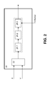
- Fig. 2 shows a heart monitor according to the invention (20), the part of the cardiac pacemaker (10) Fig. 1 can be.
- the cardiac monitor (20) has a signal input for accepting pressure or volume data or equivalent replacement quantities of a heart. These form an input signal of the heart monitor (20).
- the signal input can be connected to other components of the cardiac pacemaker (10) or directly with suitable measuring sensors, such as pressure or force sensors.
- the pacemaker is preferably designed, in a manner known per se, to determine a ventricular volume by means of an intraventricular impedance measurement.
- the inside An impedance to be measured in a ventricle of a heart is essentially determined by the blood volume enclosed by the ventricle, since the blood has a higher conductivity than the surrounding cardiac tissue (myocardium).
- the measurements of the intracardiac and in particular the intraventricular impedance as well as the evaluation of the impedance curve for determining a ventricular volume are basically known and therefore need not be described in detail here.
- Measured variables which represent a pressure prevailing in the ventricle can be recorded, for example, by means of a pressure measuring sensor arranged in the ventricle. This can, as already indicated, be part of a ventricular electrode lead of the cardiac pacemaker (10).
- the pressure sensor can also be an independent sensor which is designed to transmit pressure measurement values wirelessly to the signal input of the heart monitor (20).
- the pressure measuring sensor can act, for example, passively in the manner of a transponder. Other methods and sensors for determining the pressure prevailing in the ventricle are indicated at the beginning.
- the signal input (22) of the heart monitor (20) has two inputs in the exemplary embodiment shown here, namely an input for pressure readings or equivalent quantities and a second input for volume readings or equivalent quantities. This results in a two-channel input signal whose signal values are each formed by a pair of values of which one value represents a pressure measurement value and the other value represents a volume measurement value. The value pairs are numbered in chronological order.
- this signal input (22) of the heart monitor (20) is connected to an evaluation unit (24), which, as in Fig. 2 indicated, constructed in three stages.
- a first stage of the evaluation unit (24) is designed to segment the input signal consisting of signal value pairs such that each segment of the input signal reflects one cardiac cycle. This is done in the embodiment shown here in that the first stage (24.1) of the evaluation unit (24) is connected to a marker signal input, which is connected to a known marker channel of the cardiac pacemaker (10).
- marker signals received which represent the occurrence and the respective time of a cardiac event, such as an R-wave.
- Such marker signals are basically known and need not be explained in detail here.
- the first stage (24.1) of the evaluation unit (24) segments the input signal.
- Each segment of the input signal thus obtained represents a cardiac cycle and also represents a pV diagram representing the course of the pressure in the ventricle over the course of the volume in the ventricle. Exemplary diagrams are in Fig. 3 displayed.
- the evaluation unit (24) performs the analysis of the direction of rotation of the represented by the signal value pairs pV diagram described above by generating a two-dimensional coordinate system with an origin in the center of each pV diagram and for each measurement point (signal value pair) a vector from the center of Coordinate system determined at a respective measuring point to determine the direction of rotation of successive measuring points. This should be monotonous in one direction. If individual pairs of signal pairs cause a reversal of the direction of rotation, these signal value pairs are eliminated or corrected (see page 3,17 - page 4,14).
- the evaluation unit (24) also has a second evaluation stage (24.2), which evaluates each segment of the input signal in the sense as described above by the second evaluation stage (24.2) of the evaluation unit (24) checks each segment of the input signal as to whether the respective segment of the input signal represents a pV diagram for which the derived quality features meet the quality criteria.
- the second evaluation stage (24.2) of the evaluation unit (24) is designed to compare a corrected input signal segment generated by it with the respectively original segment of the input signal (morphology, area, Ratio circumference to area, distance between start and end point or number of measured values) and, depending on a respective comparison result, to decide whether the corrected pV diagram is suitable for further evaluation or not.
- the evaluation unit (24) and in particular its third evaluation stage (24.3) is finally connected to a control unit and / or at least one stimulation unit of the cardiac pacemaker (10) such that the evaluation unit (24) the delivery of stimulation pulses by the pacemaker (10) via the Can affect electrode lines.
- the cardiac pacemaker (10) acts as a cardiac stimulator and is designed to deliver electrical stimulation pulses via a cardiac stimulator in a manner known per se to the myocardium of a respective chamber (ventricle or atrium) of a heart Way to trigger a stimulated contraction of the respective heart chamber.
- ATD atrioventricular delay time
- VVD interventricular delay time
- the evaluation unit (24) is designed to vary the duration of a respective atrio-ventricular delay time and a respective interventricular delay time, in order first to determine the residual volume Vo, as required for determining the contractility index (Emax).
- the heart rate can be selectively modulated in order to realize a change in the filling state at the beginning of the systole and thus a preload variation.
- the evaluation unit (24) is designed to vary the atrioventricular delay time and / or the interventricular delay time and / or the pacing rate in order to optimize the atrioventricular delay time and / or the interventricular delay time and / or the pacing rate To determine sizes for which a global optimum of resulting from the third evaluation stage (24.3) derived from the pressure-volume diagram sizes.
- the various components of the heart monitor (20) can be distributed to different physical entities, such as the pacemaker (10) and the external or patient device (12) or the central service center (14).
- the heart monitor (20) as a whole is part of the implantable cardiac pacemaker (10).
- the parameter values generated by the third evaluation stage (24.3) of the heart monitor (20) and derived from the input signal are also available at an output (28) of the third evaluation stage (24.3) of the evaluation unit (24).
- This output (28) is preferably connected to a memory and / or a telemetry unit of the cardiac pacemaker (10) in order to be able to transmit the derived parameter values telemetrically to the patient device (12) and from there to the central service center (14).
- the central service center (14) can then be designed to derive further values from the received derived parameter values, for example trends that reflect the development of the parameter values, and to provide or make available to a treating physician.
- the cardiac monitor (20) may be used to monitor, for example, the effectiveness of cardiac resynchronization therapy (CRT) or to better monitor long-term outcome using clinically-accepted parameters.
- CRT cardiac resynchronization therapy
Landscapes
- Health & Medical Sciences (AREA)
- Life Sciences & Earth Sciences (AREA)
- Cardiology (AREA)
- Heart & Thoracic Surgery (AREA)
- Engineering & Computer Science (AREA)
- Veterinary Medicine (AREA)
- Biomedical Technology (AREA)
- Animal Behavior & Ethology (AREA)
- General Health & Medical Sciences (AREA)
- Public Health (AREA)
- Biophysics (AREA)
- Nuclear Medicine, Radiotherapy & Molecular Imaging (AREA)
- Radiology & Medical Imaging (AREA)
- Physiology (AREA)
- Physics & Mathematics (AREA)
- Pathology (AREA)
- Medical Informatics (AREA)
- Molecular Biology (AREA)
- Surgery (AREA)
- Hospice & Palliative Care (AREA)
- Vascular Medicine (AREA)
- Electrotherapy Devices (AREA)
- Measuring Pulse, Heart Rate, Blood Pressure Or Blood Flow (AREA)
Abstract
Description
Die Erfindung betrifft einen Herzmonitor, der wenigstens mit einem Sensor für Druck- und Volumendaten oder äquivalente Ersatzgrößen eines Herzens verbunden ist oder verbunden werden kann.The invention relates to a heart monitor which is connected or can be connected to at least one sensor for pressure and volume data or equivalent substitute quantities of a heart.
Ein solcher Herzmonitor ist beispielsweise aus
Der in dieser Anmeldung beschriebene Herzmonitor kann beispielsweise Bestandteil eines implantierbaren Impulsgenerators, wie beispielsweise eines Herzschrittmachers oder eines implantierbaren Cardioverter/Defibrillators (ICD), sein.For example, the heart monitor described in this application may be part of an implantable pulse generator, such as a pacemaker or an implantable cardioverter defibrillator (ICD).
Aufgabe der Erfindung ist es, einen verbesserten Herzmonitor zu schaffen.The object of the invention is to provide an improved heart monitor.
Erfindungsgemäß wird diese Aufgabe durch einen Herzmonitor der eingangs genannten Art gelöst, der eine Auswerteeinheit zur Verarbeitung wenigstens eines den zeitlichen Verlauf von Druck- und Volumendaten oder äquivalenten Ersatzgrößen des Herzens widerspiegelnden Eingangssignals aufweist, die derart ausgebildet ist, dass die Auswerteeinheit eine Segmentierung des Eingangssignals entsprechend einzelner abgeschlossener Herzzyklen vornimmt und so gewonnene Segmente des Eingangssignals jeweils daraufhin überprüft, ob ein jeweiliges Segment des Eingangssignals ein pV-Diagramm repräsentiert, das vorgegebenen Qualitätsbedingungen bezüglich Umlaufrichtung, Morphologie sowie Abstand zwischen Anfangs und Endwert entspricht.According to the invention, this object is achieved by a heart monitor of the type mentioned in the introduction, which has an evaluation unit for processing at least one input signal reflecting the time profile of pressure and volume data or equivalent substitute quantities of the heart, which is embodied such that the evaluation unit correspondingly segments the input signal each completed heart cycles and thus obtained segments of the input signal respectively checked to see whether a respective segment of the input signal represents a pV diagram that corresponds to predetermined quality conditions with respect to the direction of rotation, morphology and distance between the beginning and end value.
Unter einem pV-Diagramm versteht man die zweidimensionale Darstellung von Druck- und Volumenmessdaten während eines Herzzyklus, wobei die einzelnen Messpunkte gemäß ihrer zeitlichen Reihenfolge verbunden sind.A pV diagram is the two-dimensional representation of pressure and volume measurement data during a cardiac cycle, the individual measurement points being connected according to their time sequence.
PV-Diagramme sind grundsätzlich bekannt und können zur Bestimmung klinisch relevanter Parameter herangezogen werden. Beispielsweise kann die Kontraktilität der Ventrikel, der myokardiale Sauerstoffbedarf, eine Abschätzung der Effizienz des Herzens sowie die Abstimmung von Kontraktilität des Herzens und peripherer Last bestimmt werden. Diese Parameter sind bisher nur während eines Klinikaufenthaltes verfügbar. Eine kontinuierliche Nutzung ist bisher aus diesem Grund nicht möglich. Der erfindungsgemäße Herzmonitor bietet den Vorteil, eine derartige kontinuierliche Nutzung der pV-Diagramme zu ermöglichen und löst in diesem Zusammenhang weiterhin das Problem, dass nach Möglichkeit nur solche pV-Diagramme einer weiteren Auswertung unterzogen werden sollten, die auf plausible und stabile Messwerte zurückgehen. Daher prüft der erfindungsgemäße Herzmonitor, ob das einen jeweiligen Herzzyklus repräsentierende pV-Diagramm stabil ist und den vorgegebenen Qualitätsbedingungen entspricht. Geringe Abweichungen sind dabei zulässig, da diese beispielsweise auch Folge von schnellen Autoregulationsmechanismen und/oder Laständerungen sein können.PV diagrams are generally known and can be used to determine clinically relevant parameters. For example, ventricular contractility, myocardial oxygen demand, cardiac efficiency estimation, and cardiac contractility and peripheral load balancing may be determined. These parameters are so far only available during a hospital stay. Continuous use is not possible for this reason. The cardiac monitor according to the invention offers the advantage of enabling such a continuous use of the pV diagrams and, in this context, furthermore solves the problem that, if possible, only those pV diagrams should be subjected to further evaluation, which are based on plausible and stable measured values. The heart monitor according to the invention therefore checks whether the pV diagram representing a respective cardiac cycle is stable and corresponds to the prescribed quality conditions. Minor deviations are permissible, since they can also be the result, for example, of rapid autoregulation mechanisms and / or load changes.
Vorzugsweise ist die Auswerteeinheit dazu ausgebildet, aufeinander folgende Signalwertepaare des Eingangssignals hinsichtlich einer Umlaufrichtung eines durch die Signalwertepaare repräsentierten pV-Diagramms auszuwerten. Dabei kann die Auswerteeinheit ausgebildet sein, die Umlaufrichtung eines jeweils durch die Signalwertepaare repräsentierten pV-Diagramms durch Auswerten der Drehung zweidimensionaler Vektoren zu bestimmen, indem sie ein zweidimensionales Koordinatensystem mit einem Ursprung im Zentrum eines jeweiligen pV-Diagramms generiert und für jeden Messpunkt (Signalwertepaar) einen Vektor vom Mittelpunkt des Koordinatensystems zu einem jeweiligen Messpunkt bestimmt, um die Umlaufrichtung aufeinander folgender Messpunkte zu bestimmen. Die Umlaufrichtung eines durch die Signalwertepaare repräsentierten pV-Diagramms ist deshalb ein geeignetes Kriterium zur Überprüfung der Plausibilität der Signalwertepaare, da ein tatsächliches pV-Diagramm immer nur eine feste Umlaufrichtung hat. Sollten die Messwerte ein pV-Diagramm repräsentieren, das einen Wechsel in der Umlaufrichtung aufweist, kann dies nur auf einen fehlerhaften Signalwert zurückgehen. Dementsprechend ist es gemäß einer bevorzugten Ausführungsvariante vorgesehen, dass die Auswerteeinheit ausgebildet ist, die Umlaufrichtung eines jeweiligen durch Signalwertepaare repräsentierten pV-Diagramms dazu zu verwenden, ungültige Signalwertepaare (also solche Signalwertepaare, die eine der allgemeinen Umlaufrichtung entgegen gerichtete Umlaufrichtung ergeben) zu erkennen und ggf. zu korrigieren. Dies kann beispielsweise dadurch geschehen, dass die Auswerteeinheit ausgebildet ist, solche Signalwertepaare zu verwerfen, die eine abweichende Umlaufrichtung haben.Preferably, the evaluation unit is designed to evaluate successive signal value pairs of the input signal with respect to a direction of rotation of a pV diagram represented by the signal value pairs. In this case, the evaluation unit can be designed to determine the direction of rotation of a pV diagram represented in each case by the signal value pairs by evaluating the rotation of two-dimensional vectors by generating a two-dimensional coordinate system with an origin in the center of a respective pV diagram and for each measurement point (signal value pair). determines a vector from the center of the coordinate system to a respective measurement point to determine the direction of rotation of successive measurement points. The circulation direction of a pV diagram represented by the signal value pairs is therefore a suitable criterion for checking the plausibility of the signal value pairs, since an actual pV diagram always has only one fixed circulation direction. If the measured values represent a pV diagram, the change in the direction of rotation This can only be due to a faulty signal value. Accordingly, it is provided according to a preferred embodiment, that the evaluation unit is designed to use the direction of rotation of each represented by signal value pairs pV diagram to recognize invalid signal value pairs (ie, such signal value pairs that give the general direction of rotation opposite direction of rotation) and, if necessary . to correct. This can be done, for example, in that the evaluation unit is designed to reject such signal value pairs which have a different direction of rotation.
Eine weitere bevorzugte Ausführungsvariante eines Herzmonitors bezieht sich auf Herzmonitore mit einem Markersignaleingang für Markersignale, die definierte Ereignisse innerhalb eines jeweiligen Herzzyklus einschließlich des Zeitpunktes ihres Auftretens repräsentieren. Hierbei ist die Auswerteeinheit vorzugsweise so ausgebildet, dass sie eine Segmentierung des Eingangssignals anhand über den Markersignaleingang zu empfangender Markersignale vornimmt.Another preferred embodiment of a heart monitor relates to cardiac monitors having a marker signal input for marker signals representing defined events within a respective cardiac cycle, including the time of their occurrence. In this case, the evaluation unit is preferably designed such that it carries out a segmentation of the input signal on the basis of the marker signal input to be received marker signals.
Zusätzlich oder alternativ kann die Auswerteeinheit auch ausgebildet sein, eine Segmentierung des Eingangssignals anhand morphologischer Merkmale der durch die Signalwertepaare des Eingangssignals repräsentierten pV-Diagramme vorzunehmen.Additionally or alternatively, the evaluation unit may also be designed to perform a segmentation of the input signal on the basis of morphological features of the pV diagrams represented by the signal value pairs of the input signal.
Eine weitere Alternative besteht darin, dass der Herzmonitor einen EKG-Signaleingang für ein intrakardiales EKG-Signal oder Oberflächen EKG aufweist, wobei die Auswerteeinheit ausgebildet ist, eine Segmentierung des Eingangssignals anhand eines über den EKG-Signaleingang zu empfangenden intrakardialen EKG-Signals vorzunehmen.Another alternative is that the cardiac monitor has an ECG signal input for an intracardiac ECG signal or surface ECG, wherein the evaluation unit is designed to perform a segmentation of the input signal on the basis of an intracardiac ECG signal to be received via the ECG signal input.
Weiterhin kann die Auswerteeinheit ausgebildet sein, eine Approximation der durch die Signalwertepaare repräsentierten pV-Diagramme durch Ersatzfunktionen, wie Ellipsen, Rechtecke, Trapeze oder dergleichen, vorzunehmen. Dabei kann die Auswahl einer möglichst günstigen Geometrie entweder manuell erfolgen und somit manuell vorgegeben werden oder auch automatisch durch die Auswerteeinheit erfolgen.Furthermore, the evaluation unit can be designed to perform an approximation of the pV diagrams represented by the signal value pairs by substitute functions, such as ellipses, rectangles, trapezoids or the like. In this case, the selection of a geometry that is as favorable as possible can be carried out either manually and thus be specified manually or else automatically by the evaluation unit.
Hinsichtlich einer Korrektur möglicherweise fehlerhafter Signalwertepaare ist es bevorzugt, wenn die Auswerteeinheit ausgebildet ist, Kreuzungspunkte der durch die Signalwertepaare repräsentierten pV-Diagramme, die sich durch die Verbindung aufeinander folgender Signalwertepaare ergeben, automatisch zu erkennen und zu korrigieren. Solche Kreuzungspunkte entstehen beispielsweise durch Messrauschen oder Mess-Ungenauigkeiten und kommen in einem tatsächlichen pV-Diagramm nicht vor.With regard to a correction of possibly faulty signal value pairs, it is preferred if the evaluation unit is designed to automatically detect and correct crossing points of the pV diagrams represented by the signal value pairs, which result from the connection of successive signal value pairs. Such crossing points are caused, for example, by measurement noise or measurement inaccuracies and do not occur in an actual pV diagram.
Im Hinblick auf die weitere Auswertung wie zuvor beschrieben korrigierter pV-Diagramme ist die Auswerteeinheit ausgebildet, ein jeweils korrigiertes pV-Diagramm mit dem jeweils entsprechenden, ursprünglichen unkorrigierten pV-Diagramm zur Ableitung von Qualitätsmerkmalen zu vergleichen. Hierbei ist es bevorzugt, wenn die Auswerteeinheit ausgebildet ist, den Vergleich anhand von Kriterien, wie zum Beispiel der Anzahl der korrigierten Signalwertepaare, der Unterschiede in der Morphologie der repräsentierten pV-Diagramme, der Flächendifferenzen zwischen den repräsentierten pV-Diagrammen, Schwerpunktverschiebungen zwischen den pV-Diagrammen, der Entfernung zwischen End- und Startpunkt eines jeweiligen pV-Diagramms oder dergleichen durchzuführen und in Abhängigkeit eines jeweiligen Vergleichsergebnisses mit vorgegebenen Qualitätskriterien zu vergleichen und zu entscheiden, ob sich ein jeweiliges korrigiertes pV-Diagramm für eine weitere Auswertung eignet oder nicht.With regard to the further evaluation as previously described corrected pV diagrams, the evaluation unit is designed to compare a respectively corrected pV diagram with the respectively corresponding original uncorrected pV diagram for the derivation of quality features. In this case, it is preferred, when the evaluation unit is designed, to compare based on criteria such as the number of corrected signal value pairs, the differences in the morphology of the represented pV diagrams, the area differences between the represented pV diagrams, center of gravity shifts between the pV -Diagrams, the distance between the end and start point of each pV diagram or the like to perform and compare depending on a respective comparison result with predetermined quality criteria and to decide whether a respective corrected pV diagram for further evaluation is suitable or not.
Außerdem kann die Auswerteeinheit ausgebildet sein, alle ein jeweiliges pV-Diagramm repräsentierenden Signalwertepaare durch eine Hüllkurve zu umschließen. Hierbei kann die Auswerteeinheit ausgebildet sein, eine jeweils größtmögliche Hüllkurve zu bestimmen, die keinen, oder die kleinstmögliche, die die meisten oder alle Signalwertepaare eines ein jeweiliges pV-Diagramm repräsentierenden Signalsegmentes umhüllt.In addition, the evaluation unit can be designed to enclose all signal value pairs representing a respective pV diagram by means of an envelope curve. In this case, the evaluation unit can be designed to determine a maximum possible envelope curve, which envelopes none, or the smallest possible, which covers most or all signal value pairs of a signal segment representing a respective pV diagram.
Alternativ kann die Auswerteeinheit auch ausgebildet sein, eine ein jeweiliges pV-Diagramm repräsentierende Folge von Signalwertepaaren durch eine oder mehrere Parameter-optimierte Funktionen zu approximieren.Alternatively, the evaluation unit can also be designed to approximate a sequence of signal value pairs representing a respective pV diagram by one or more parameter-optimized functions.
Die bis hierhin beschriebenen vorausgewerteten Signalwertepaare - genauer gesagt: Folgen von Signalwertepaaren des Eingangssignals, die ein jeweiliges pV-Diagramm repräsentieren - können anschließend weiter ausgewertet werden. Hierzu ist die Auswerteeinheit vorzugsweise ausgebildet, aus einem jeweiligen durch Signalwertepaare repräsentierten pV-Diagramm (linker oder rechter Ventrikel) jeweils einen Wert für einen oder mehrere der folgenden Parameter abzuleiten:
- Kontraktilitätsindex (Emax = ESP/(ESV - Vo)): Emax entspricht dem Anstieg jener Geraden die durch Vo gehend die pV-Kurve am linken oberen Rand gerade noch berührt (siehe
Fig. 3 ). Der End-systolische Druck ESP ist jener Druck im Ventrikel der sich am Ende der Auswurfphase einstellt. - End-diastolisches Volumen (EDV): Das maximale Blutvolumen im Ventrikel, gemessen am Ende der Füllphase jedes Herzschlages
- End-systolisches Volumen (ESV): Das minimale Blutvolumen im Ventrikel, gemessen am Ende der Austreibungsphase
- Schlagvolumen (SV): Das Schlagvolumen eines einzelnen Herzschlages (SV = EDV - ESV)
- Ejektionsfraktion (EF = SV/EDV)
- Effektive arterielle Elastanz (Ea): Die effektive Elastanz des an den linken Ventrikel anschließenden arteriellen Systems (Ea = ESP/SV)
- Externe Arbeit (EW): Jener Anteil der Herzarbeit, die direkt in mechanische Energie umgewandelt wird. Bestimmt wird dieser Parameter durch die Berechnung der Fläche innerhalb der PV-Kurve;
- Potentielle Energie (PE): Jener Anteil der Herzarbeit, die nicht in mechanische Energie umgewandelt werden kann. PE bezeichnet eine Fläche, die an die PV-Kurve linksseitig anschließt. Sie verläuft ausgehend vom Residualvolumen (Vo) über jene Gerade die Vo mit dem End-systolischen Druck ESP verbindet, weiter dem Verlauf der isovolumetrischen Relaxation folgend, bis zum Öffnen der Einstromklappe und wieder zurück zu Vo (siehe
Fig. 3 ). Möglichkeiten zur direkten Bestimmung von Vo sind durch die Veränderung von Elektrostimulationsparametern wie AV und VV Verzögerung, Herzrate aber auch durch die künstliche Erzeugung von Extrasystolen gegeben da die verschiedenen End-systolischen Drücke auf einer Geraden liegen, deren Schnittpunkt mit der Volumenachse, Vo entspricht. Bei der Verwendung von Ersatzgrößen werden diese Merkmale entsprechend transformiert. Vo wird zu diesem Zweck geschätzt oder aus echokardiographischen Vermessungen bestimmt. - Druck-Volumen Fläche (PVA): Der Gesamte Energiebedarf des Herzens während eines Schlages (PVA = PE + EW). Diese Größe kann zur Bestimmung des myokardialen Sauerstoffbedarfs verwendet werden;
- EW/PE: Die Effizienz des Herzens kann aus dem Verhältnis von EW und PE bestimmt werden. Je größer dieses Verhältnis ist umso höher ist der Anteil jener Energie die vom Herzen in mechanische Arbeit umgesetzt werden kann. Als Alternative wird für den gleichen Zweck auch EW/PVA, also das Verhältnis von geleisteter mechanischer Arbeit zum Gesamten Energiebedarf des Herzens, verwendet;
- Arteriell-ventrikuläre-Kopplung (AVC): AVC = Ea/Emax = (ESV-Vo)/ SV. Dieser Parameter kann auch ohne Messung des linksventrikulären Drucks bestimmt werden.
- Preload-Recruitable-Stroke_Work (PRSW): Beschreibt das Verhältnis von EW und EDV und dient als Vor- und Nachlast unabhängiger Parameter für die myokardiale Kontraktilität (alternative zu Emax).
- Contractility Index (Emax = ESP / (ESV - Vo)): Emax corresponds to the slope of the line just touching the pV curve at the top left edge (see
Fig. 3 ). The end systolic pressure ESP is the pressure in the ventricle that sets at the end of the ejection phase. - End Diastolic Volume (EDV): The maximum volume of blood in the ventricle, measured at the end of the filling phase of each heartbeat
- End-systolic Volume (ESV): The minimum volume of blood in the ventricle, measured at the end of the expulsion phase
- Stroke volume (SV): The stroke volume of a single heartbeat (SV = EDV - ESV)
- Ejection fraction (EF = SV / EDP)
- Effective arterial elastance (Ea): The effective elastance of the arterial system following the left ventricle (Ea = ESP / SV)
- External work (EW): That part of the heart work that is converted directly into mechanical energy. This parameter is determined by calculating the area within the PV curve;
- Potential Energy (PE): That part of the heart's work that can not be converted into mechanical energy. PE denotes an area that adjoins the PV curve on the left side. It proceeds from the residual volume (Vo) via the straight line that connects Vo to the end-systolic pressure ESP, and continues along the course of the isovolumetric Relaxation following, until the opening of the inlet flap and back to Vo (see
Fig. 3 ). Options for the direct determination of Vo are given by the change of electrostimulation parameters such as AV and VV delay, heart rate but also by the artificial generation of extrasystoles because the various end-systolic pressures lie on a straight line whose intersection with the volume axis, Vo corresponds. When using substitute sizes, these features are transformed accordingly. Vo is estimated for this purpose or determined from echocardiographic measurements. - Pressure Volume Area (PVA): The total energy demand of the heart during a beat (PVA = PE + EW). This size can be used to determine myocardial oxygen demand;
- EW / PE: The efficiency of the heart can be determined from the ratio of EW and PE. The larger this ratio is, the higher the proportion of energy that can be converted from the heart to mechanical work. As an alternative, EW / PVA, ie the ratio of mechanical work to the total energy requirement of the heart, is used for the same purpose;
- Arterial-Ventricular Coupling (AVC): AVC = Ea / Emax = (ESV-Vo) / SV. This parameter can also be determined without measuring left ventricular pressure.
- Preload-Recruitable-Stroke_Work (PRSW): Describes the relationship between EW and EDP and serves as a pre- and post-load of independent parameters for myocardial contractility (alternative to Emax).
Für die Berechnung von Emax, PE, PVA sowie AVC ist eine Bestimmung des Residualvolumens Vo erforderlich. Das Residualvolumen ist jenes Blutvolumen bei dem eine Kontraktion des Ventrikels zu einem End-systolischen Druck von 0 mmHg führen würde. Dieses kann durch bildgebende Verfahren wie bspw. Echokardiographie erfolgen, oder für den Fall, dass nur Änderungen betrachtet werden, auch auf einen hinreichend niedrigen festen Wert gesetzt werden. Da Vo im Allgemeinen klein gegenüber ESV ist.For the calculation of Emax, PE, PVA and AVC, a determination of the residual volume Vo is required. Residual volume is the volume of blood at which contraction of the ventricle would result in a final systolic pressure of 0 mmHg. This can be done by imaging techniques such as echocardiography, or, if only changes are considered, set to a reasonably low fixed value. Since Vo is generally small compared to ESV.
Gemäß bevorzugter Ausführungsvarianten der Erfindung kann der Herzmonitor mit einem Herzstimulator verbunden sein und ausgebildet sein, die Abgabe von Stimulationsimpulsen durch den Herzstimulator zu beeinflussen. Hierbei ist die Auswerteeinheit vorzugsweise dazu ausgebildet, im Rahmen der weiteren Auswertung von z. B. transienten Kontraktilitätsänderungen (Emax) durch eine Variation von Stimulationsparametern, wie die atrioventrikuläre Verzögerungszeit (AVD), die interventrikuläre Verzögerungszeit (VVD), die Stimulationsfrequenz oder dergleichen anzuregen, um ein jeweiliges Residualvolumen Vo bestimmen zu können.According to preferred embodiments of the invention, the heart monitor may be connected to a heart stimulator and be designed to influence the delivery of stimulation pulses by the heart stimulator. In this case, the evaluation unit is preferably designed to be used in the further evaluation of z. For example, transient contractility changes (Emax) may be stimulated by a variation of stimulation parameters, such as atrio-ventricular delay time (AVD), interventricular delay time (VVD), pacing rate, or the like to determine a respective residual volume Vo.
Alternativ hierzu kann die Auswerteeinheit auch dazu ausgebildet sein, das Residualvolumen Vo auch ohne Variation von Stimulationsparametern ganz ohne eine Stimulation des jeweiligen Herzens dadurch automatisch vorzunehmen, dass die Auswerteeinheit transiente Kontraktilitätsänderung zur Aktualisierung des Wertes für das Residualvolumen Vo nutzt.Alternatively, the evaluation unit can also be configured to automatically perform the residual volume Vo without any stimulation of the respective heart even without variation of stimulation parameters in that the evaluation unit uses transient contractility change to update the value for the residual volume Vo.
Gemäß einer ebenfalls bevorzugten Ausführungsvariante ist der Herzmonitor mit einem Herzstimulator verbunden und ausgebildet, die Abgabe von Stimulationsimpulsen durch den Herzstimulator zu beeinflussen, wobei die Auswerteeinheit weiter ausgebildet ist, eine der vorstehend genannten abgeleiteten Größen, wie Emax, EDV, ESV etc. zur gleichzeitigen Optimierung von einer atrioventrikulären Überleitungszeit (AVD) und oder interventrikulären Überleitungszeit (VVD) und oder Stimulationsfrequenz zu verwenden, indem die atrioventrikuläre Übergangszeit (AVD) und/oder die interventrikuläre Übergangszeit (VVD) und/oder die Stimulationsfrequenz so lange variiert werden, bis sich ein globales Optimum ergibt.According to a likewise preferred embodiment, the heart monitor is connected to a heart stimulator and designed to influence the delivery of stimulation pulses by the heart stimulator, wherein the evaluation unit is further developed, one of the aforementioned derived variables, such as Emax, EDV, ESV, etc. for simultaneous optimization of an atrioventricular conduction time (AVD) and / or interventricular conduction time (VVD) and / or pacing rate, by varying the atrio-ventricular transition time (AVD) and / or the interventricular transition time (VVD) and / or the pacing rate until a global one Optimum results.
Hinsichtlich der Aufnahme der Messwerte, die schließlich - ggf. nach entsprechender Verstärkung etc. - die Signalwerte des Eingangssignals ergeben, ist der Signalmonitor vorzugsweise mit entsprechenden Messsensoren verbunden. Diese Messsensoren können beispielsweise Drucksensoren oder Kraftsensoren sein, aber auch Abstandssensoren, wie nachfolgend näher ausgeführt ist.With regard to the recording of the measured values, which finally give the signal values of the input signal, if necessary after appropriate amplification, etc., the signal monitor is preferably connected to corresponding measuring sensors. These measuring sensors can be, for example, pressure sensors or force sensors, but also distance sensors, as explained in more detail below.
Verwendete Drucksensoren können beispielsweise in typischen Elektrodenleitungen eines Herzstimulators angeordnet sein und damit eine Druckmessung direkt in einer Herzkammer ermöglichen. Zur Bestimmung des Drucks in der linken Herzkammer kann der Druck während der Diastole durch eine Messung des Drucks im linken Vorhof und während der Systole durch eine Messung des arteriellen Drucks in der Aorta bestimmt werden.Used pressure sensors can be arranged for example in typical electrode lines of a heart stimulator and thus a pressure measurement directly in a heart chamber enable. To determine the pressure in the left ventricle, the pressure during diastole can be determined by measuring the pressure in the left atrium and during systole by measuring the arterial pressure in the aorta.
Ein Drucksensor kann auch in einer Coronarsinus-Elektrodenleitung integriert sein. Während einer Systole steigt der Druck in den Coronargefäßen infolge der Kontraktion des Herzmuskels an. Durch Messung dieser Druckänderung, beispielsweise durch einen Drucksensor in einer Coronarsinus-Elektrodenleitung, kann eine Abschätzung des Ventrikeldrucks erfolgen.A pressure sensor may also be integrated in a coronary sinus electrode line. During systole, pressure in the coronary vessels increases due to contraction of the heart muscle. By measuring this change in pressure, for example by a pressure sensor in a coronary sinus electrode line, an estimate of the ventricular pressure can be made.
Mit Hilfe von Kraftsensoren kann beispielsweise eine Kraftmessung zwischen zwei fixen Punkten an der Herzwand erfolgen. Dies ist bei Patienten anwendbar, die Myokardbereiche mit nicht kontrahierendem Gewebe aufweisen.By means of force sensors, for example, a force measurement can take place between two fixed points on the heart wall. This is applicable to patients having myocardial areas with non-contracting tissue.
Zusätzlich oder alternativ kann auch eine mechanische Fixiereinrichtung zur Positionierung einer Coronarsinus-Elektrode genutzt werden, um die Kraftentwicklung während der Systole und damit indirekt den Druckverlauf im Inneren der Herzkammer zu erfassen.Additionally or alternatively, a mechanical fixing device for positioning a coronary sinus electrode can be used to detect the force development during systole and thus indirectly the pressure curve in the interior of the heart chamber.
Als weitere Alternative können lokale, direkt ins Myokard eingebrachte Kraft- oder DruckSensoren vorgesehen sein, die zur Bestimmung der Druckentwicklung im Inneren des Ventrikels verwendet werden können.As a further alternative, local force or pressure sensors introduced directly into the myocardium can be provided, which can be used to determine the pressure development inside the ventricle.
Hinsichtlich des Einsatzes von Abstandssensoren besteht die Möglichkeit, eine Abstandsmessung zwischen zwei fixen Punkten an der Herzwand vorzunehmen. Diese Methode ist bei Patienten anwendbar, die Myokardbereiche mit nicht kontrahierendem Gewebe aufweisen.With regard to the use of distance sensors, it is possible to make a distance measurement between two fixed points on the heart wall. This method is applicable to patients who have myocardial areas with non-contracting tissue.
Hinsichtlich des Einsatzes von Drucksensoren, die mit dem Herzmonitor verbunden sind, besteht auch die Möglichkeit, diese im Septum zwischen den Herzkammern anzuordnen. Diese können so ausgebildet sein, dass sie den Druck oder eine Kraftentwicklung im Septum erfassen oder alternativ transseptal direkt den Ventrikeldruck messen.With regard to the use of pressure sensors which are connected to the heart monitor, it is also possible to arrange them in the septum between the heart chambers. These can be designed so that they detect the pressure or a force development in the septum or alternatively measure transseptal directly the ventricular pressure.
Auch kann der Herzmonitor mit einem Druckmesskatheter verbunden sein, mit dem langzeitstabile Druckmessungen im Ventrikel oder im Endokard durchgeführt werden können, um so Messwerte zu gewinnen, die dem Herzmonitor übermittelt werden.Also, the cardiac monitor may be connected to a pressure measuring catheter that can be used to perform long-term stable pressure measurements in the ventricle or endocardium to obtain readings that are communicated to the cardiac monitor.
Alternativ können auch solche Drucksensoren im Inneren eines oder beider Ventrikel oder im Endokard angebracht sein, die eine Sendeeinheit enthalten und ihre Messwerte drahtlos an den Herzmonitor übertragen.Alternatively, such pressure sensors can be mounted inside one or both ventricles or in the endocardium, which contain a transmitting unit and transmit their measured values wirelessly to the heart monitor.
Alternativ oder zusätzlich kann der Herzmonitor auch ausgebildet sein, ventrikuläre Drücke aus Ersatzdrücken zu ermitteln, die mit Drucksensoren an ventrikulären Elektrodenleitungen oder mit Drucksensoren, die innen oder außen an der Herzwand befestigt sind oder minimalinvasiv in das Perikard eingebracht wurden gemessen werden.Alternatively or additionally, the cardiac monitor may also be designed to detect ventricular pressures from surrogate pressures that are measured with pressure sensors on ventricular electrode leads or with pressure sensors attached inside or outside the heart wall or inserted minimally invasively into the pericardium.
Alternativ oder zusätzlich kann der Herzmonitor auch ausgebildet sein, ventrikuläre Volumina aus Ersatzgrößen (Impedanzmessung, Ultraschall-Laufzeitmessung, Dämpfung von RF-Signalen, Dämpfung von Schallsignalen) zu ermitteln, die mit Abstandssensoren gemessen werden, die an ventrikulären Elektrodenleitungen oder innen oder außen an der Herzwand befestigt sind oder minimalinvasiv in das Perikard eingebracht wurden.Alternatively or additionally, the cardiac monitor can also be designed to determine ventricular volumes from substitute variables (impedance measurement, ultrasonic transit time measurement, attenuation of RF signals, attenuation of sound signals) which are measured using distance sensors which are located on ventricular electrode lines or inside or outside at the Cardiac wall attached or minimally invasive were introduced into the pericardium.
Der Herzmonitor kann alternativ auch ausgebildet sein, einen ventrikulären Druck durch Auswerten eines intrakardialen Impedanzverlaufs (z. B. durch Differenziation) abzuleiten. Die hierzu erforderliche Bestimmung des intrakardialen Impedanzverlaufs ist grundsätzlich bekannt und andernorts ausführlich beschrieben.Alternatively, the cardiac monitor may be configured to derive a ventricular pressure by evaluating an intracardiac impedance history (eg, by differentiation). The determination of the intracardiac impedance curve required for this purpose is known in principle and described in detail elsewhere.
Der Herzmonitor kann grundsätzlich als selbständiges Gerät, beispielsweise als selbständiges Implantat, ausgeführt sein. Er kann außerdem Bestandteil eines implantierbaren medizinischen Gerätes, wie beispielsweise eines Herzschrittmachers oder eines Cardioverters/Defibrillators (ICD) sein. Dabei kann das implantierbare medizinische Gerät auch ein Implantat im näheren Sinne umfassen sowie ein externes Gerät, das telemetrisch mit dem Implantat im engeren Sinne verbunden ist. Der Herzmonitor der hier beschriebenen Art und insbesondere dessen Auswerteeinheit können dabei ganz oder in Teilen sowohl Bestandteil des Implantats im engeren Sinne oder des externen Geräts oder beider oder weiterer Komponenten des medizinischen Geräts sein.The heart monitor can basically be designed as an independent device, for example as an independent implant. It may also be part of an implantable medical device, such as a pacemaker or a cardioverter / defibrillator (ICD). In this case, the implantable medical device may also include an implant in the closer sense, as well as an external device that is telemetrically connected to the implant in the strict sense. The heart monitor of the type described here, and in particular the evaluation unit, can be part or all of it in whole or in part the implant in the strict sense or the external device or both or other components of the medical device.
Die Erfindung soll nun anhand eines Ausführungsbeispiels mit Bezug auf die Figuren näher erläutert werden. Von diesen zeigt:
- Fig. 1:
- Ein medizinisches Gerät umfassend ein Implantat und ein externes Gerät sowie ein zentrales Servicecenter;
- Fig. 2:
- einen Herzmonitor als medizinisches Gerät bzw. Bestandteil eines medizini- schen Gerätes; und
- Fig. 3:
- Diagramme zur Erläuterung eines Druck-Volumen-Verlaufs im Inneren eines Ventrikels sowie hieraus abzuleitender Größen.
- Fig. 1:
- A medical device comprising an implant and an external device and a central service center;
- Fig. 2:
- a heart monitor as a medical device or component of a medical device; and
- 3:
- Diagrams to explain a pressure-volume curve inside a ventricle and the variables to be derived therefrom.
Messgrößen, die einen im Ventrikel herrschenden Druck repräsentieren, können beispielsweise mittels eines im Ventrikel angeordneten Druckmesssensors aufgenommen werden. Dieser kann, wie eingangs bereits angedeutet, Bestandteil einer ventrikulären Elektrodenleitung des Herzschrittmachers (10) sein. Der Drucksensor kann auch ein selbständiger Sensor sein, der ausgebildet ist, Druckmesswerte drahtlos an den Signaleingang des Herzmonitors (20) zu übermitteln. Der Druckmesssensor kann dabei beispielsweise passiv nach Art eines Transponders wirken. Weitere Methoden und Sensoren zur Bestimmung des im Ventrikel herrschenden Drucks sind eingangs angedeutet.Measured variables which represent a pressure prevailing in the ventricle can be recorded, for example, by means of a pressure measuring sensor arranged in the ventricle. This can, as already indicated, be part of a ventricular electrode lead of the cardiac pacemaker (10). The pressure sensor can also be an independent sensor which is designed to transmit pressure measurement values wirelessly to the signal input of the heart monitor (20). The pressure measuring sensor can act, for example, passively in the manner of a transponder. Other methods and sensors for determining the pressure prevailing in the ventricle are indicated at the beginning.
Der Signaleingang (22) des Herzmonitors (20) besitzt im hier dargestellten Ausführungsbeispiel zwei Eingänge, nämlich einen Eingang für Druckmesswerte oder äquivalente Größen und einen zweiten Eingang für Volumenmesswerte oder äquivalente Größen. Hieraus ergibt sich ein zweikanaliges Eingangssignal, dessen Signalwerte jeweils von einem Wertepaar gebildet wird von denen ein Wert einen Druckmesswert repräsentiert und der andere Wert einen Volumenmesswert repräsentiert. Die Wertepaare werden in Ihrer zeitlichen Reihenfolge nummeriert.The signal input (22) of the heart monitor (20) has two inputs in the exemplary embodiment shown here, namely an input for pressure readings or equivalent quantities and a second input for volume readings or equivalent quantities. This results in a two-channel input signal whose signal values are each formed by a pair of values of which one value represents a pressure measurement value and the other value represents a volume measurement value. The value pairs are numbered in chronological order.
Mit diesem Signaleingang (22) des Herzmonitors (20) ist eine Auswerteeinheit (24) verbunden, die, wie in
Die Auswerteeinheit (24) führt die eingangs beschriebene Analyse der Umlaufrichtung des durch die Signalwertepaare repräsentierten pV-Diagramms durch, indem sie ein zweidimensionales Koordinatensystem mit einem Ursprung im Zentrum eines jeweiligen pV-Diagramms generiert und für jeden Messpunkt (Signalwertepaar) einen Vektor vom Mittelpunkt des Koordinatensystems zu einem jeweiligen Messpunkt bestimmt um die Umlaufrichtung aufeinanderfolgender Messpunkte zu bestimmen. Diese sollte monoton in eine Richtung verlaufen. Falls einzelne Signalwertepaare eine Umkehrung der Umlaufrichtung bewirken, werden diese Signalwertepaare eliminiert bzw. korrigiert (siehe Seite 3,17 - Seite 4,14). Eben diesen Auswertungen des Eingangssignals durch die zweite Auswertungsstufe (24.2) der Auswerteeinheit (24) kann die zweite Auswertungsstufe (24.2) mit der Auswerteeinheit 24 auch die weiteren eingangs beschriebenen Eigenschaften besitzen, die zu einer Vorauswertung einer jeweiligen Sequenz des Eingangssignals führen, also beispielsweise dazu ausgebildet sein, Kreuzungspunkte der durch die Signalwertepaare repräsentierten pV-Diagramme zu erkennen und zu beheben.The evaluation unit (24) performs the analysis of the direction of rotation of the represented by the signal value pairs pV diagram described above by generating a two-dimensional coordinate system with an origin in the center of each pV diagram and for each measurement point (signal value pair) a vector from the center of Coordinate system determined at a respective measuring point to determine the direction of rotation of successive measuring points. This should be monotonous in one direction. If individual pairs of signal pairs cause a reversal of the direction of rotation, these signal value pairs are eliminated or corrected (see page 3,17 - page 4,14). Precisely these evaluations of the input signal by the second evaluation stage (24.2) of the evaluation unit (24), the second evaluation stage (24.2) with the evaluation unit 24 also have the other properties described above, leading to a pre-evaluation of a respective sequence of the input signal, so for example be formed to detect and eliminate crossing points of the represented by the signal value pairs pV diagrams.
Die Auswerteeinheit (24) besitzt außerdem eine zweite Auswertestufe (24.2), die jedes Segment des Eingangssignals in dem Sinne vorauswertet, wie dies eingangs beschrieben ist, indem die zweite Auswertestufe (24.2) der Auswertungseinheit (24) jedes Segment des Eingangssignals daraufhin überprüft, ob das jeweilige Segment des Eingangssignals ein pV-Diagramm repräsentiert, für das die abgeleiteten Qualitätsmerkmale den Qualitätskriterien entsprechen. Dafür ist die zweite Auswertungsstufe (24.2) der Auswerteeinheit (24) dazu ausgebildet, ein von ihr generiertes korrigiertes Eingangssignalsegment mit dem jeweils ursprünglichen Segment des Eingangssignals zu vergleichen (Morphologie, Fläche, Verhältnis Umfang zu Fläche, Abstand zwischen Anfangs und Endpunkt oder Anzahl der Messwerte) und in Abhängigkeit eines jeweiligen Vergleichsergebnisses zu entscheiden, ob sich das korrigierte pV-Diagramm für eine weitere Auswertung eignet oder nicht.The evaluation unit (24) also has a second evaluation stage (24.2), which evaluates each segment of the input signal in the sense as described above by the second evaluation stage (24.2) of the evaluation unit (24) checks each segment of the input signal as to whether the respective segment of the input signal represents a pV diagram for which the derived quality features meet the quality criteria. For this purpose, the second evaluation stage (24.2) of the evaluation unit (24) is designed to compare a corrected input signal segment generated by it with the respectively original segment of the input signal (morphology, area, Ratio circumference to area, distance between start and end point or number of measured values) and, depending on a respective comparison result, to decide whether the corrected pV diagram is suitable for further evaluation or not.
Eine dritte Auswertungsstufe (24.3) der Auswerteeinheit (24) ist schließlich dazu ausgebildet, die von der zweiten Auswertungsstufe (24.2) generierten korrigierten Eingangssignalsegmente derart zu verarbeiten, dass die dritte Auswertungsstufe (24.3) aus diesen Eingangssignalsegmenten jeweils einen Wert (28) für einen oder mehrere der folgenden Parameter ableitet:
- Kontraktilitätsindex (Emax = ESP/(ESV - Vo)): Emax entspricht dem Anstieg jener Geraden die durch Vo gehend die pV-Kurve am linken oberen Rand gerade noch berührt (siehe
Fig. 3 ). - End-diastolisches Volumen (EDV): Das maximale Blutvolumen im Ventrikel, gemessen am Ende der Füllphase jedes Herzschlages
- End-systolisches Volumen (ESV): Das minimale Blutvolumen im Ventrikel, gemessen am Ende der Austreibungsphase
- Schlagvolumen (SV): Das Schlagvolumen eines einzelnen Herzschlages (SV = EDV - ESV)
- Ejektionsfraktion (EF = SV/EDV)
- Effektive arterielle Elastanz (Ea): Die effektive Elastanz des an den linken Ventrikel anschließenden arteriellen Systems (Ea = ESP/SV)
- Externe Arbeit (EW): Jener Anteil der Herzarbeit, die direkt in mechanische Energie umgewandelt wird. Bestimmt wird dieser Parameter durch die Berechnung der Fläche innerhalb der PV-Kurve;
- Potentielle Energie (PE): Jener Anteil der Herzarbeit, die nicht in mechanische Energie umgewandelt werden kann. PE bezeichnet eine Fläche, die an die PV-Kurve linksseitig anschließt. Sie verläuft ausgehend vom Residualvolumen (Vo) über jene Gerade die Vo mit dem End-systolischen Druck verbindet, weiter dem Verlauf der isovolumetrischen Relaxation folgend, bis zum Öffnen der Einstromklappe und wieder zurück zu Vo (siehe
Fig. 3 ). Möglichkeiten zur direkten Bestimmung von Vo sind durch die Veränderung von Elektrostimulationsparametern wie AV und VV Verzögerung, Herzrate aber auch durch die künstliche Erzeugung von Extrasystolen gegeben da die verschiedene End-systolischen Drücke auf einer Linie liegen, deren Schnittpunkt mit der Volumenachse, Vo entspricht. Bei der Verwendung von Ersatzgrößen werden diese Merkmale entsprechend transformiert. Vo wird zu diesem Zweck geschätzt oder aus echokardiographischen Vermessungen bestimmt. - Druck-Volumen Fläche (PVA): Der Gesamte Energiebedarf des Herzens während eines Schlages (PVA = PE + EW). Diese Größe kann zur Bestimmung des myokardialen Sauerstoffbedarfs verwendet werden;
- EW/PE: Die Effizienz des Herzens kann aus dem Verhältnis von EW und PE bestimmt werden. Je größer dieses Verhältnis ist umso höher ist der Anteil jener Energie die vom Herzen in mechanische Arbeit umgesetzt werden kann. Als Alternative wird für den gleichen Zweck auch EW/PVA, also das Verhältnis von geleisteter mechanischer Arbeit zum Gesamten Energiebedarf des Herzens, verwendet;
- Arteriell-ventrikuläre-Kopplung (AVC): AVC = Ea/Emax = (ESV-Vo)/ SV. Dieser Parameter kann auch ohne Messung des linksventrikulären Drucks bestimmt werden.
- Preload-Recruitable-Stroke_Work (PRSW): Beschreibt das Verhältnis von EW und EDV und dient als Vor- und Nachlast unabhängiger Parameter für die myokardiale Kontraktilität (alternative zu Emax).
- Contractility Index (Emax = ESP / (ESV - Vo)): Emax corresponds to the slope of the line just touching the pV curve at the top left edge (see
Fig. 3 ). - End Diastolic Volume (EDV): The maximum volume of blood in the ventricle, measured at the end of the filling phase of each heartbeat
- End-systolic Volume (ESV): The minimum volume of blood in the ventricle, measured at the end of the expulsion phase
- Stroke volume (SV): The stroke volume of a single heartbeat (SV = EDV - ESV)
- Ejection fraction (EF = SV / EDP)
- Effective arterial elastance (Ea): The effective elastance of the arterial system following the left ventricle (Ea = ESP / SV)
- External work (EW): That part of the heart work that is converted directly into mechanical energy. This parameter is determined by calculating the area within the PV curve;
- Potential Energy (PE): That part of the heart's work that can not be converted into mechanical energy. PE denotes an area that adjoins the PV curve on the left side. It proceeds from the residual volume (Vo) via the straight line connecting Vo to the end-systolic pressure, following the course of the isovolumetric relaxation, until the inlet valve opens and back again to Vo (see
Fig. 3 ). Options for the direct determination of Vo are given by the change of electrostimulation parameters such as AV and VV delay, heart rate but also by the artificial generation of extrasystoles because the various end-systolic pressures lie on a line whose intersection with the volume axis, Vo corresponds. When using substitute sizes, these features are transformed accordingly. Vo is estimated for this purpose or determined from echocardiographic measurements. - Pressure Volume Area (PVA): The total energy demand of the heart during a beat (PVA = PE + EW). This size can be used to determine myocardial oxygen demand;
- EW / PE: The efficiency of the heart can be determined from the ratio of EW and PE. The larger this ratio is, the higher the proportion of energy that can be converted from the heart to mechanical work. As an alternative, EW / PVA, ie the ratio of mechanical work to the total energy requirement of the heart, is used for the same purpose;
- Arterial-Ventricular Coupling (AVC): AVC = Ea / Emax = (ESV-Vo) / SV. This parameter can also be determined without measuring left ventricular pressure.
- Preload-Recruitable-Stroke_Work (PRSW): Describes the relationship between EW and EDP and serves as a pre- and post-load of independent parameters for myocardial contractility (alternative to Emax).
Einige dieser Parameter sind in den in
Die Auswerteeinheit (24) und insbesondere deren dritte Auswertestufe (24.3) ist schließlich mit einer Steuereinheit und/oder wenigstens einer Stimulationseinheit des Herzschrittmachers (10) derart verbunden, dass die Auswerteeinheit (24) die Abgabe von Stimulationsimpulsen durch den Herzschrittmacher (10) über dessen Elektrodenleitungen beeinflussen kann.The evaluation unit (24) and in particular its third evaluation stage (24.3) is finally connected to a control unit and / or at least one stimulation unit of the cardiac pacemaker (10) such that the evaluation unit (24) the delivery of stimulation pulses by the pacemaker (10) via the Can affect electrode lines.
Wie grundsätzlich bekannt, wirkt der Herzschrittmacher (10) als Herzstimulator und ist als solcher ausgebildet, über einen Herzstimulator angeschlossene Elektrodenleitungen elektrische Stimulationsimpulse in an sich bekannter Art und Weise an das Myokard einer jeweiligen Kammer (Ventrikel oder Atrium) eines Herzens abzugeben, um auf diese Weise eine stimulierte Kontraktion der jeweiligen Herzkammer auszulösen.As is generally known, the cardiac pacemaker (10) acts as a cardiac stimulator and is designed to deliver electrical stimulation pulses via a cardiac stimulator in a manner known per se to the myocardium of a respective chamber (ventricle or atrium) of a heart Way to trigger a stimulated contraction of the respective heart chamber.
Das Verhalten eines stimulierten Herzens hängt maßgeblich davon ab, zu welchem Zeitpunkt Stimulationsimpulse an die verschiedenen Kammern eines Herzens abgegeben werden. Hierfür maßgebliche Zeitintervalle in der Steuerung eines Herzstimulators sind eine atrioventrikuläre Verzögerungszeit (atrioventricular delay AVD) und eine interventrikuläre Verzögerungszeit (VVD), die im Falle des in
Konkret ist die Auswerteeinheit (24) dazu ausgebildet, die Dauer einer jeweiligen atrioventrikulären Verzögerungszeit und einer jeweiligen interventrikulären Verzögerungszeit zu variieren, um zum einen auf diese Weise das Residualvolumen Vo zu bestimmen, wie es zur Bestimmung des Kontraktilitätsindex (Emax) erforderlich ist. Alternativ kann zur Bestimmung des Residualvolumens die Herzfrequenz gezielt moduliert werden, um eine Änderung des Füllzustandes zu Beginn der Systole und damit eine Preloadvariation zu realisieren.Concretely, the evaluation unit (24) is designed to vary the duration of a respective atrio-ventricular delay time and a respective interventricular delay time, in order first to determine the residual volume Vo, as required for determining the contractility index (Emax). Alternatively, to determine the residual volume, the heart rate can be selectively modulated in order to realize a change in the filling state at the beginning of the systole and thus a preload variation.
Zum anderen ist die Auswerteeinheit (24) dazu ausgebildet, die atrioventrikuläre Verzögerungszeit und/oder die interventrikuläre Verzögerungszeit und/oder die Stimulationsfrequenz zu variieren, um auf diese Weise für die atrioventrikuläre Verzögerungszeit und/oder die interventrikuläre Verzögerungszeit und/oder die Stimulationsfrequenz aufeinander abgestimmt optimierte Größen zu ermitteln, für die sich ein globales Optimum der von der dritten Auswertungsstufe (24.3) aus dem Druck-Volumendiagramm abgeleiteten Größen ergibt.On the other hand, the evaluation unit (24) is designed to vary the atrioventricular delay time and / or the interventricular delay time and / or the pacing rate in order to optimize the atrioventricular delay time and / or the interventricular delay time and / or the pacing rate To determine sizes for which a global optimum of resulting from the third evaluation stage (24.3) derived from the pressure-volume diagram sizes.
Wie bereits angedeutet können die verschiedenen Bestandteile des Herzmonitors (20) auf verschiedene physische Entitäten, beispielsweise den Herzschrittmacher (10) und das externe oder Patientengerät (12) oder auch das zentrale Servicecenter (14), verteilt sein.As already indicated, the various components of the heart monitor (20) can be distributed to different physical entities, such as the pacemaker (10) and the external or patient device (12) or the central service center (14).
Bevorzugt ist jedoch, dass der Herzmonitor (20) als Ganzes Bestandteil des implantierbaren Herzschrittmachers (10) ist. Die von der dritten Auswertungsstufe (24.3) des Herzmonitors (20) generierten und aus dem Eingangssignal abgeleiteten Parameterwerte stehen außerdem an einem Ausgang (28) der dritten Auswertungsstufe (24.3) der Auswerteeinheit (24) bereit. Dieser Ausgang (28) ist vorzugsweise mit einem Speicher und/oder einer Telemetrieeinheit des Herzschrittmachers (10) verbunden, um die abgeleiteten Parameterwerte auf diese Weise telemetrisch zum Patientengerät (12) und von dort aus weiter zum zentralen Servicecenter (14) übertragen zu können. Das zentrale Servicecenter (14) kann dann dazu ausgebildet sein, aus den empfangenen abgeleiteten Parameterwerten weitere Werte, beispielsweise Trends, die die Entwicklung der Parameterwerte widerspiegeln, abzuleiten und einem behandelnden Arzt zuzuleiten oder zur Verfügung zu stellen.However, it is preferred that the heart monitor (20) as a whole is part of the implantable cardiac pacemaker (10). The parameter values generated by the third evaluation stage (24.3) of the heart monitor (20) and derived from the input signal are also available at an output (28) of the third evaluation stage (24.3) of the evaluation unit (24). This output (28) is preferably connected to a memory and / or a telemetry unit of the cardiac pacemaker (10) in order to be able to transmit the derived parameter values telemetrically to the patient device (12) and from there to the central service center (14). The central service center (14) can then be designed to derive further values from the received derived parameter values, for example trends that reflect the development of the parameter values, and to provide or make available to a treating physician.
Auf diese Weise kann der Herzmonitor (20) dazu benutzt werden, beispielsweise die Wirksamkeit einer kardialen Resynchronisationstherapie (CRT) zu überwachen oder ein besseres Monitoring eines Langzeitverlaufs unter Verwendung klinisch anerkannter Parameter durchzuführen.In this way, the cardiac monitor (20) may be used to monitor, for example, the effectiveness of cardiac resynchronization therapy (CRT) or to better monitor long-term outcome using clinically-accepted parameters.
Es ergeben sich in der Folge erweiterte Optimierungsmöglichkeiten der Implantatparameter (also der Einstellgrößen des Herzschrittmachers) durch eine genauere Bestimmung eines aktuellen Herzstatus. Außerdem sind mit Hilfe der erfindungsgemäß gewonnenen pV-Diagramme auch Rückschlüsse auf das periphere System möglich.This results in the result of extended optimization possibilities of the implant parameters (ie the setting parameters of the pacemaker) by a more accurate determination of a current heart status. In addition, conclusions about the peripheral system are possible with the aid of the pV diagrams obtained according to the invention.
Claims (15)
Applications Claiming Priority (1)
| Application Number | Priority Date | Filing Date | Title |
|---|---|---|---|
| DE102009002397A DE102009002397A1 (en) | 2009-04-15 | 2009-04-15 | heart monitor |
Publications (3)
| Publication Number | Publication Date |
|---|---|
| EP2241348A2 true EP2241348A2 (en) | 2010-10-20 |
| EP2241348A3 EP2241348A3 (en) | 2010-11-24 |
| EP2241348B1 EP2241348B1 (en) | 2015-05-06 |
Family
ID=42321184
Family Applications (1)
| Application Number | Title | Priority Date | Filing Date |
|---|---|---|---|
| EP20100156625 Not-in-force EP2241348B1 (en) | 2009-04-15 | 2010-03-16 | Heart monitor |
Country Status (3)
| Country | Link |
|---|---|
| US (1) | US8521265B2 (en) |
| EP (1) | EP2241348B1 (en) |
| DE (1) | DE102009002397A1 (en) |
Cited By (7)
| Publication number | Priority date | Publication date | Assignee | Title |
|---|---|---|---|---|
| EP3347090A4 (en) * | 2015-09-11 | 2019-04-24 | BackBeat Medical, Inc. | Methods and systems for treating cardiac malfunction |
| US10369333B2 (en) | 2005-03-02 | 2019-08-06 | Backbeat Medical, Inc. | Methods and apparatus to increase secretion of endogenous naturetic hormones |
| US10441794B2 (en) | 2012-12-21 | 2019-10-15 | Backbeat Medical, Inc. | Methods and systems for lowering blood pressure through reduction of ventricle filling |
| US10485658B2 (en) | 2016-04-22 | 2019-11-26 | Backbeat Medical, Inc. | Methods and systems for controlling blood pressure |
| US10596380B2 (en) | 2006-09-25 | 2020-03-24 | Backbeat Medical, Inc. | Methods and apparatus to stimulate heart atria |
| US11083894B2 (en) | 2008-09-08 | 2021-08-10 | Backbeat Medical, Llc | Methods and apparatus to stimulate the heart |
| US11406829B2 (en) | 2004-02-12 | 2022-08-09 | Backbeat Medical, Llc | Cardiac stimulation apparatus and method for the control of hypertension |
Families Citing this family (8)
| Publication number | Priority date | Publication date | Assignee | Title |
|---|---|---|---|---|
| EP2561811A1 (en) | 2011-08-23 | 2013-02-27 | BIOTRONIK SE & Co. KG | Comparison of right-ventricular and left-ventricular contraction using an accelerometer in an artery close to the heart |
| CN103377298B (en) * | 2012-04-24 | 2016-08-03 | 富士通株式会社 | The method and apparatus of Selection parameter |
| US10918858B2 (en) | 2016-07-20 | 2021-02-16 | Cardiac Pacemakers, Inc. | Cardiac volume sensing via an implantable medical device in support of cardiac resynchronization therapy |
| US10478629B2 (en) | 2016-07-20 | 2019-11-19 | Cardiac Pacemakers, Inc. | Leadless cardiac pacemaker for generating cardiac pressure volume loop |
| US10874860B2 (en) | 2016-07-20 | 2020-12-29 | Cardiac Pacemakers, Inc. | Method and system for determining a cardiac cycle pace time in accordance with metabolic demand in a leadless cardiac pacemaker system |
| US11147965B2 (en) | 2016-07-20 | 2021-10-19 | Cardiac Pacemakers, Inc. | Method and system for determining pace timing in a leadless cardiac pacemaker system |
| US10765871B2 (en) | 2016-10-27 | 2020-09-08 | Cardiac Pacemakers, Inc. | Implantable medical device with pressure sensor |
| EP3668592B1 (en) | 2017-08-18 | 2021-11-17 | Cardiac Pacemakers, Inc. | Implantable medical device with pressure sensor |
Citations (4)
| Publication number | Priority date | Publication date | Assignee | Title |
|---|---|---|---|---|
| US20040030356A1 (en) | 2002-04-03 | 2004-02-12 | Markus Osypka | Method and apparatus for automatic determination of hemodynamically optimal cardiac pacing parameter values |
| US20070066898A1 (en) | 2005-08-19 | 2007-03-22 | Hendriks Randall A | Systems and methods for capture and display of blood pressure and ultrasound data |
| US20070129765A1 (en) | 2005-12-07 | 2007-06-07 | Cardiac Pacemakers, Inc. | Implantable medical device for generating cardiac pressure-volume loop and optimizing therapy |
| US7286875B1 (en) | 2004-05-03 | 2007-10-23 | Pacesetter, Inc. | Monitoring ventricular contractions using an implantable stimulation device |
Family Cites Families (6)
| Publication number | Priority date | Publication date | Assignee | Title |
|---|---|---|---|---|
| US5643327A (en) * | 1995-06-20 | 1997-07-01 | Pacesetter, Inc. | Pacemaker and method having optimized A-V delay by using the evoked depolarization potential as an indicia of cardiac output |
| IL115538A (en) * | 1995-10-06 | 2000-10-31 | Pyrotec Ltd | Method and system for determination of the pressure-volume relationship of the heart |
| EP1510173B1 (en) * | 2003-09-01 | 2017-04-05 | BIOTRONIK SE & Co. KG | Intracardial impedance measuring device |
| DE10361143A1 (en) * | 2003-09-01 | 2005-03-24 | Biotronik Gmbh & Co. Kg | Intracardiac impedance measurement arrangement |
| US7363077B1 (en) * | 2004-11-09 | 2008-04-22 | Pacesetters, Inc. | Adaptive timing interval control method for treating congestive heart failure |
| WO2006107922A2 (en) * | 2005-04-04 | 2006-10-12 | The Trustees Of Columbia University In The City Of New York | Methods for optimization of biventricular pacing, devices and systems useful therefor |
-
2009
- 2009-04-15 DE DE102009002397A patent/DE102009002397A1/en not_active Withdrawn
-
2010
- 2010-03-16 EP EP20100156625 patent/EP2241348B1/en not_active Not-in-force
- 2010-03-30 US US12/749,723 patent/US8521265B2/en active Active
Patent Citations (4)
| Publication number | Priority date | Publication date | Assignee | Title |
|---|---|---|---|---|
| US20040030356A1 (en) | 2002-04-03 | 2004-02-12 | Markus Osypka | Method and apparatus for automatic determination of hemodynamically optimal cardiac pacing parameter values |
| US7286875B1 (en) | 2004-05-03 | 2007-10-23 | Pacesetter, Inc. | Monitoring ventricular contractions using an implantable stimulation device |
| US20070066898A1 (en) | 2005-08-19 | 2007-03-22 | Hendriks Randall A | Systems and methods for capture and display of blood pressure and ultrasound data |
| US20070129765A1 (en) | 2005-12-07 | 2007-06-07 | Cardiac Pacemakers, Inc. | Implantable medical device for generating cardiac pressure-volume loop and optimizing therapy |
Cited By (20)
| Publication number | Priority date | Publication date | Assignee | Title |
|---|---|---|---|---|
| US11406829B2 (en) | 2004-02-12 | 2022-08-09 | Backbeat Medical, Llc | Cardiac stimulation apparatus and method for the control of hypertension |
| US11577059B2 (en) | 2005-03-02 | 2023-02-14 | Backbeat Medical, Llc | Methods and apparatus to increase secretion of endogenous naturetic hormones |
| US10369333B2 (en) | 2005-03-02 | 2019-08-06 | Backbeat Medical, Inc. | Methods and apparatus to increase secretion of endogenous naturetic hormones |
| US11529520B2 (en) | 2006-09-25 | 2022-12-20 | Backbeat Medical, Llc | Methods and apparatus to stimulate heart atria |
| US10596380B2 (en) | 2006-09-25 | 2020-03-24 | Backbeat Medical, Inc. | Methods and apparatus to stimulate heart atria |
| US11759639B2 (en) | 2008-09-08 | 2023-09-19 | Backbeat Medical, Llc | Methods and apparatus to stimulate the heart |
| US11083894B2 (en) | 2008-09-08 | 2021-08-10 | Backbeat Medical, Llc | Methods and apparatus to stimulate the heart |
| US11452875B2 (en) | 2012-12-21 | 2022-09-27 | Backbeat Medical, Llc | Methods and systems for lowering blood pressure through reduction of ventricle filling |
| US10610689B2 (en) | 2012-12-21 | 2020-04-07 | Backbeat Medical, Inc. | Methods and systems for lowering blood pressure through reduction of ventricle filling |
| US10967188B2 (en) | 2012-12-21 | 2021-04-06 | Backbeat Medical, Llc | Methods and systems for controlling blood pressure by controlling atrial pressure |
| US11097108B2 (en) | 2012-12-21 | 2021-08-24 | Backbeat Medical, Llc | Methods and systems for lowering blood pressure through reduction of ventricle filling |
| US11712567B2 (en) | 2012-12-21 | 2023-08-01 | Backbeat Medical, Llc | Methods and systems for controlling blood pressure by controlling atrial pressure |
| US10441794B2 (en) | 2012-12-21 | 2019-10-15 | Backbeat Medical, Inc. | Methods and systems for lowering blood pressure through reduction of ventricle filling |
| AU2016319787B2 (en) * | 2015-09-11 | 2021-05-27 | Backbeat Medical, Llc | Methods and systems for treating cardiac malfunction |
| EP3347090A4 (en) * | 2015-09-11 | 2019-04-24 | BackBeat Medical, Inc. | Methods and systems for treating cardiac malfunction |
| US10342982B2 (en) | 2015-09-11 | 2019-07-09 | Backbeat Medical, Inc. | Methods and systems for treating cardiac malfunction |
| US11389658B2 (en) | 2015-09-11 | 2022-07-19 | Backbeat Medical, Llc | Methods and systems for treating cardiac malfunction |
| US11426589B2 (en) | 2016-04-22 | 2022-08-30 | Backbeat Medical, Llc | Methods and systems for controlling blood pressure |
| US10485658B2 (en) | 2016-04-22 | 2019-11-26 | Backbeat Medical, Inc. | Methods and systems for controlling blood pressure |
| US11969598B2 (en) | 2016-04-22 | 2024-04-30 | Backbeat Medical, Llc | Methods and systems for controlling blood pressure |
Also Published As
| Publication number | Publication date |
|---|---|
| EP2241348B1 (en) | 2015-05-06 |
| EP2241348A3 (en) | 2010-11-24 |
| DE102009002397A1 (en) | 2010-10-21 |
| US20100268294A1 (en) | 2010-10-21 |
| US8521265B2 (en) | 2013-08-27 |
Similar Documents
| Publication | Publication Date | Title |
|---|---|---|
| EP2241348B1 (en) | Heart monitor | |
| EP2433565B1 (en) | Implantable medical device | |
| DE69929448T2 (en) | IMPLANTABLE SENSOR WITH WIRELESS COMMUNICATION | |
| DE60118433T2 (en) | IMPLANTABLE MEDICAL DEVICE FOR MONITORING CONGESTIVE HEART FAILURE | |
| DE602004006105T2 (en) | DEVICE FOR EVALUATING AND OPTIMIZING VENTRICULAR SYNCHRONIZATION | |
| EP1510173B1 (en) | Intracardial impedance measuring device | |
| EP1586348B1 (en) | Electrotherapeutic apparatus | |
| EP2060299B1 (en) | Biventricular heart stimulator | |
| DE69926502T2 (en) | HEART RINSING USING ADJUSTABLE ATRIO-VENTRICULAR DELAY INTERVALS | |
| DE60106645T2 (en) | APPARATUS FOR MEASURING THE MEDIUM BLOOD PRESSURE IN THE LUNG ARTERY FROM THE HEART CHAMBER WITH A MOBILE MONITORING DEVICE | |
| DE60132016T2 (en) | IMPLANTABLE MEDICAL DEVICE FOR THE TREATMENT OF MECHANICAL HEART FUNCTIONAL DISORDERS BY MEANS OF ELECTRICAL STIMULATION | |
| DE60215458T2 (en) | Apparatus for the automatic determination of hemodynamically optimal cardiac stimulation parameter values | |
| EP2968916B1 (en) | Medical device with multiple sensor fusion | |
| EP2395445A2 (en) | Method and arrangement for creating an individualized, computer-aided model of a system, and a corresponding computer program and a corresponding machine-readable storage medium | |
| EP2415396B1 (en) | Heart monitor | |
| EP1762270A1 (en) | Device for determining cardiac parameters | |
| DE60131041T2 (en) | Implantable cardiac device for monitoring the worsening or improvement of heart disease | |
| DE10119394A1 (en) | Pacemaking with regulated coronary sinus flow, involves sampling speed of blood flow through coronary sinus of patient's heart, generating pacemaker pulse as function of sampled speed | |
| DE112020003151T5 (en) | BLOOD PUMP WITH ELECTROCARDIOGRAM (ECG) MONITORING, DEFIBRILLATION AND STIMULATION CAPABILITY | |
| DE60216970T2 (en) | IMPLANTABLE HEART STIMULATING DEVICE AND SYSTEM COMPRISING THIS DEVICE | |
| EP2561811A1 (en) | Comparison of right-ventricular and left-ventricular contraction using an accelerometer in an artery close to the heart | |
| DE102007057227B4 (en) | Cardiac stimulation arrangement | |
| EP2279775B1 (en) | Cardiac stimulator for stimulating one ventricle in response to an event sensed in the contralateral ventricle | |
| DE602004005122T2 (en) | An active implantable medical device having means for adjusting the maximum rate of ventricular pacing as a function of a patient's hemodynamic condition | |
| DE202007018531U1 (en) | Dual chamber pacing coils for atrial defibrillation and ventricular pacing |
Legal Events
| Date | Code | Title | Description |
|---|---|---|---|
| PUAI | Public reference made under article 153(3) epc to a published international application that has entered the european phase |
Free format text: ORIGINAL CODE: 0009012 |
|
| AK | Designated contracting states |
Kind code of ref document: A2 Designated state(s): AT BE BG CH CY CZ DE DK EE ES FI FR GB GR HR HU IE IS IT LI LT LU LV MC MK MT NL NO PL PT RO SE SI SK SM TR |
|
| AX | Request for extension of the european patent |
Extension state: AL BA ME RS |
|
| PUAL | Search report despatched |
Free format text: ORIGINAL CODE: 0009013 |
|
| AK | Designated contracting states |
Kind code of ref document: A3 Designated state(s): AT BE BG CH CY CZ DE DK EE ES FI FR GB GR HR HU IE IS IT LI LT LU LV MC MK MT NL NO PL PT RO SE SI SK SM TR |
|
| AX | Request for extension of the european patent |
Extension state: AL BA ME RS |
|
| 17P | Request for examination filed |
Effective date: 20110502 |
|
| 17Q | First examination report despatched |
Effective date: 20130523 |
|
| RIC1 | Information provided on ipc code assigned before grant |
Ipc: A61B 5/0215 20060101ALI20141217BHEP Ipc: A61N 1/362 20060101ALI20141217BHEP Ipc: A61B 5/053 20060101ALI20141217BHEP Ipc: A61B 5/107 20060101ALN20141217BHEP Ipc: A61N 1/365 20060101AFI20141217BHEP |
|
| GRAP | Despatch of communication of intention to grant a patent |
Free format text: ORIGINAL CODE: EPIDOSNIGR1 |
|
| INTG | Intention to grant announced |
Effective date: 20150203 |
|
| RIN1 | Information on inventor provided before grant (corrected) |
Inventor name: CZYGAN, GERALD Inventor name: SKERL, OLAF Inventor name: KRAEMER, THOMAS Inventor name: LIPPERT, MICHAEL Inventor name: VOLLKRON, MICHAEL |
|
| GRAS | Grant fee paid |
Free format text: ORIGINAL CODE: EPIDOSNIGR3 |
|
| GRAA | (expected) grant |
Free format text: ORIGINAL CODE: 0009210 |
|
| AK | Designated contracting states |
Kind code of ref document: B1 Designated state(s): AT BE BG CH CY CZ DE DK EE ES FI FR GB GR HR HU IE IS IT LI LT LU LV MC MK MT NL NO PL PT RO SE SI SK SM TR |
|
| REG | Reference to a national code |
Ref country code: GB Ref legal event code: FG4D Free format text: NOT ENGLISH |
|
| REG | Reference to a national code |
Ref country code: CH Ref legal event code: EP |
|
| REG | Reference to a national code |
Ref country code: IE Ref legal event code: FG4D Free format text: LANGUAGE OF EP DOCUMENT: GERMAN |
|
| REG | Reference to a national code |
Ref country code: AT Ref legal event code: REF Ref document number: 725274 Country of ref document: AT Kind code of ref document: T Effective date: 20150615 |
|
| REG | Reference to a national code |
Ref country code: DE Ref legal event code: R096 Ref document number: 502010009467 Country of ref document: DE Effective date: 20150618 |
|
| REG | Reference to a national code |
Ref country code: DE Ref legal event code: R082 Country of ref document: DE Ref country code: DE Ref legal event code: R082 Ref document number: 502010009467 Country of ref document: DE Representative=s name: RANDOLL, SOEREN, DIPL.-CHEM. UNIV. DR. RER. NA, DE |
|
| REG | Reference to a national code |
Ref country code: NL Ref legal event code: MP Effective date: 20150506 |
|
| REG | Reference to a national code |
Ref country code: LT Ref legal event code: MG4D |
|
| PG25 | Lapsed in a contracting state [announced via postgrant information from national office to epo] |
Ref country code: LT Free format text: LAPSE BECAUSE OF FAILURE TO SUBMIT A TRANSLATION OF THE DESCRIPTION OR TO PAY THE FEE WITHIN THE PRESCRIBED TIME-LIMIT Effective date: 20150506 Ref country code: ES Free format text: LAPSE BECAUSE OF FAILURE TO SUBMIT A TRANSLATION OF THE DESCRIPTION OR TO PAY THE FEE WITHIN THE PRESCRIBED TIME-LIMIT Effective date: 20150506 Ref country code: NO Free format text: LAPSE BECAUSE OF FAILURE TO SUBMIT A TRANSLATION OF THE DESCRIPTION OR TO PAY THE FEE WITHIN THE PRESCRIBED TIME-LIMIT Effective date: 20150806 Ref country code: FI Free format text: LAPSE BECAUSE OF FAILURE TO SUBMIT A TRANSLATION OF THE DESCRIPTION OR TO PAY THE FEE WITHIN THE PRESCRIBED TIME-LIMIT Effective date: 20150506 Ref country code: HR Free format text: LAPSE BECAUSE OF FAILURE TO SUBMIT A TRANSLATION OF THE DESCRIPTION OR TO PAY THE FEE WITHIN THE PRESCRIBED TIME-LIMIT Effective date: 20150506 Ref country code: PT Free format text: LAPSE BECAUSE OF FAILURE TO SUBMIT A TRANSLATION OF THE DESCRIPTION OR TO PAY THE FEE WITHIN THE PRESCRIBED TIME-LIMIT Effective date: 20150907 |
|
| PG25 | Lapsed in a contracting state [announced via postgrant information from national office to epo] |
Ref country code: GR Free format text: LAPSE BECAUSE OF FAILURE TO SUBMIT A TRANSLATION OF THE DESCRIPTION OR TO PAY THE FEE WITHIN THE PRESCRIBED TIME-LIMIT Effective date: 20150807 Ref country code: BG Free format text: LAPSE BECAUSE OF FAILURE TO SUBMIT A TRANSLATION OF THE DESCRIPTION OR TO PAY THE FEE WITHIN THE PRESCRIBED TIME-LIMIT Effective date: 20150806 Ref country code: LV Free format text: LAPSE BECAUSE OF FAILURE TO SUBMIT A TRANSLATION OF THE DESCRIPTION OR TO PAY THE FEE WITHIN THE PRESCRIBED TIME-LIMIT Effective date: 20150506 Ref country code: IS Free format text: LAPSE BECAUSE OF FAILURE TO SUBMIT A TRANSLATION OF THE DESCRIPTION OR TO PAY THE FEE WITHIN THE PRESCRIBED TIME-LIMIT Effective date: 20150906 |
|
| PG25 | Lapsed in a contracting state [announced via postgrant information from national office to epo] |
Ref country code: DK Free format text: LAPSE BECAUSE OF FAILURE TO SUBMIT A TRANSLATION OF THE DESCRIPTION OR TO PAY THE FEE WITHIN THE PRESCRIBED TIME-LIMIT Effective date: 20150506 Ref country code: EE Free format text: LAPSE BECAUSE OF FAILURE TO SUBMIT A TRANSLATION OF THE DESCRIPTION OR TO PAY THE FEE WITHIN THE PRESCRIBED TIME-LIMIT Effective date: 20150506 |
|
| REG | Reference to a national code |
Ref country code: DE Ref legal event code: R097 Ref document number: 502010009467 Country of ref document: DE |
|
| PG25 | Lapsed in a contracting state [announced via postgrant information from national office to epo] |
Ref country code: PL Free format text: LAPSE BECAUSE OF FAILURE TO SUBMIT A TRANSLATION OF THE DESCRIPTION OR TO PAY THE FEE WITHIN THE PRESCRIBED TIME-LIMIT Effective date: 20150506 Ref country code: SK Free format text: LAPSE BECAUSE OF FAILURE TO SUBMIT A TRANSLATION OF THE DESCRIPTION OR TO PAY THE FEE WITHIN THE PRESCRIBED TIME-LIMIT Effective date: 20150506 Ref country code: RO Free format text: LAPSE BECAUSE OF NON-PAYMENT OF DUE FEES Effective date: 20150506 Ref country code: CZ Free format text: LAPSE BECAUSE OF FAILURE TO SUBMIT A TRANSLATION OF THE DESCRIPTION OR TO PAY THE FEE WITHIN THE PRESCRIBED TIME-LIMIT Effective date: 20150506 |
|
| PLBE | No opposition filed within time limit |
Free format text: ORIGINAL CODE: 0009261 |
|
| STAA | Information on the status of an ep patent application or granted ep patent |
Free format text: STATUS: NO OPPOSITION FILED WITHIN TIME LIMIT |
|
| 26N | No opposition filed |
Effective date: 20160209 |
|
| PG25 | Lapsed in a contracting state [announced via postgrant information from national office to epo] |
Ref country code: IT Free format text: LAPSE BECAUSE OF FAILURE TO SUBMIT A TRANSLATION OF THE DESCRIPTION OR TO PAY THE FEE WITHIN THE PRESCRIBED TIME-LIMIT Effective date: 20150506 |
|
| PG25 | Lapsed in a contracting state [announced via postgrant information from national office to epo] |
Ref country code: SI Free format text: LAPSE BECAUSE OF FAILURE TO SUBMIT A TRANSLATION OF THE DESCRIPTION OR TO PAY THE FEE WITHIN THE PRESCRIBED TIME-LIMIT Effective date: 20150506 |
|
| PG25 | Lapsed in a contracting state [announced via postgrant information from national office to epo] |
Ref country code: BE Free format text: LAPSE BECAUSE OF NON-PAYMENT OF DUE FEES Effective date: 20160331 |
|
| PG25 | Lapsed in a contracting state [announced via postgrant information from national office to epo] |
Ref country code: LU Free format text: LAPSE BECAUSE OF FAILURE TO SUBMIT A TRANSLATION OF THE DESCRIPTION OR TO PAY THE FEE WITHIN THE PRESCRIBED TIME-LIMIT Effective date: 20160316 Ref country code: MC Free format text: LAPSE BECAUSE OF FAILURE TO SUBMIT A TRANSLATION OF THE DESCRIPTION OR TO PAY THE FEE WITHIN THE PRESCRIBED TIME-LIMIT Effective date: 20150506 |
|
| GBPC | Gb: european patent ceased through non-payment of renewal fee |
Effective date: 20160316 |
|
| REG | Reference to a national code |
Ref country code: FR Ref legal event code: ST Effective date: 20161130 |
|
| PG25 | Lapsed in a contracting state [announced via postgrant information from national office to epo] |
Ref country code: GB Free format text: LAPSE BECAUSE OF NON-PAYMENT OF DUE FEES Effective date: 20160316 Ref country code: FR Free format text: LAPSE BECAUSE OF NON-PAYMENT OF DUE FEES Effective date: 20160331 |
|
| REG | Reference to a national code |
Ref country code: AT Ref legal event code: MM01 Ref document number: 725274 Country of ref document: AT Kind code of ref document: T Effective date: 20160316 |
|
| PG25 | Lapsed in a contracting state [announced via postgrant information from national office to epo] |
Ref country code: SE Free format text: LAPSE BECAUSE OF FAILURE TO SUBMIT A TRANSLATION OF THE DESCRIPTION OR TO PAY THE FEE WITHIN THE PRESCRIBED TIME-LIMIT Effective date: 20150506 Ref country code: NL Free format text: LAPSE BECAUSE OF FAILURE TO SUBMIT A TRANSLATION OF THE DESCRIPTION OR TO PAY THE FEE WITHIN THE PRESCRIBED TIME-LIMIT Effective date: 20150506 |
|
| PG25 | Lapsed in a contracting state [announced via postgrant information from national office to epo] |
Ref country code: MT Free format text: LAPSE BECAUSE OF FAILURE TO SUBMIT A TRANSLATION OF THE DESCRIPTION OR TO PAY THE FEE WITHIN THE PRESCRIBED TIME-LIMIT Effective date: 20150506 Ref country code: AT Free format text: LAPSE BECAUSE OF NON-PAYMENT OF DUE FEES Effective date: 20160316 |
|
| REG | Reference to a national code |
Ref country code: DE Ref legal event code: R082 Ref document number: 502010009467 Country of ref document: DE Ref country code: DE Ref legal event code: R081 Ref document number: 502010009467 Country of ref document: DE Owner name: BIOTRONIK SE & CO. KG, DE Free format text: FORMER OWNER: BIOTRONIK CRM PATENT AG, BAAR, CH |
|
| PG25 | Lapsed in a contracting state [announced via postgrant information from national office to epo] |
Ref country code: HU Free format text: LAPSE BECAUSE OF FAILURE TO SUBMIT A TRANSLATION OF THE DESCRIPTION OR TO PAY THE FEE WITHIN THE PRESCRIBED TIME-LIMIT; INVALID AB INITIO Effective date: 20100316 Ref country code: CY Free format text: LAPSE BECAUSE OF FAILURE TO SUBMIT A TRANSLATION OF THE DESCRIPTION OR TO PAY THE FEE WITHIN THE PRESCRIBED TIME-LIMIT Effective date: 20150506 Ref country code: SM Free format text: LAPSE BECAUSE OF FAILURE TO SUBMIT A TRANSLATION OF THE DESCRIPTION OR TO PAY THE FEE WITHIN THE PRESCRIBED TIME-LIMIT Effective date: 20150506 |
|
| PG25 | Lapsed in a contracting state [announced via postgrant information from national office to epo] |
Ref country code: TR Free format text: LAPSE BECAUSE OF FAILURE TO SUBMIT A TRANSLATION OF THE DESCRIPTION OR TO PAY THE FEE WITHIN THE PRESCRIBED TIME-LIMIT Effective date: 20150506 Ref country code: MK Free format text: LAPSE BECAUSE OF FAILURE TO SUBMIT A TRANSLATION OF THE DESCRIPTION OR TO PAY THE FEE WITHIN THE PRESCRIBED TIME-LIMIT Effective date: 20150506 |
|
| PGFP | Annual fee paid to national office [announced via postgrant information from national office to epo] |
Ref country code: IE Payment date: 20220322 Year of fee payment: 13 Ref country code: DE Payment date: 20220317 Year of fee payment: 13 Ref country code: CH Payment date: 20220324 Year of fee payment: 13 |
|
| REG | Reference to a national code |
Ref country code: DE Ref legal event code: R119 Ref document number: 502010009467 Country of ref document: DE |
|
| REG | Reference to a national code |
Ref country code: CH Ref legal event code: PL |
|
| REG | Reference to a national code |
Ref country code: IE Ref legal event code: MM4A |
|
| PG25 | Lapsed in a contracting state [announced via postgrant information from national office to epo] |
Ref country code: LI Free format text: LAPSE BECAUSE OF NON-PAYMENT OF DUE FEES Effective date: 20230331 Ref country code: IE Free format text: LAPSE BECAUSE OF NON-PAYMENT OF DUE FEES Effective date: 20230316 Ref country code: DE Free format text: LAPSE BECAUSE OF NON-PAYMENT OF DUE FEES Effective date: 20231003 Ref country code: CH Free format text: LAPSE BECAUSE OF NON-PAYMENT OF DUE FEES Effective date: 20230331 |