EP2236708A1 - Vehicle door lock device - Google Patents
Vehicle door lock device Download PDFInfo
- Publication number
- EP2236708A1 EP2236708A1 EP20080853041 EP08853041A EP2236708A1 EP 2236708 A1 EP2236708 A1 EP 2236708A1 EP 20080853041 EP20080853041 EP 20080853041 EP 08853041 A EP08853041 A EP 08853041A EP 2236708 A1 EP2236708 A1 EP 2236708A1
- Authority
- EP
- European Patent Office
- Prior art keywords
- lever
- opening
- opening link
- condition
- door lock
- Prior art date
- Legal status (The legal status is an assumption and is not a legal conclusion. Google has not performed a legal analysis and makes no representation as to the accuracy of the status listed.)
- Withdrawn
Links
Images


Classifications
-
- E—FIXED CONSTRUCTIONS
- E05—LOCKS; KEYS; WINDOW OR DOOR FITTINGS; SAFES
- E05B—LOCKS; ACCESSORIES THEREFOR; HANDCUFFS
- E05B85/00—Details of vehicle locks not provided for in groups E05B77/00 - E05B83/00
- E05B85/01—Mechanical arrangements specially adapted for hands-free locking or unlocking
-
- E—FIXED CONSTRUCTIONS
- E05—LOCKS; KEYS; WINDOW OR DOOR FITTINGS; SAFES
- E05B—LOCKS; ACCESSORIES THEREFOR; HANDCUFFS
- E05B81/00—Power-actuated vehicle locks
- E05B81/02—Power-actuated vehicle locks characterised by the type of actuators used
- E05B81/04—Electrical
- E05B81/06—Electrical using rotary motors
-
- E—FIXED CONSTRUCTIONS
- E05—LOCKS; KEYS; WINDOW OR DOOR FITTINGS; SAFES
- E05B—LOCKS; ACCESSORIES THEREFOR; HANDCUFFS
- E05B81/00—Power-actuated vehicle locks
- E05B81/12—Power-actuated vehicle locks characterised by the function or purpose of the powered actuators
- E05B81/16—Power-actuated vehicle locks characterised by the function or purpose of the powered actuators operating on locking elements for locking or unlocking action
-
- E—FIXED CONSTRUCTIONS
- E05—LOCKS; KEYS; WINDOW OR DOOR FITTINGS; SAFES
- E05B—LOCKS; ACCESSORIES THEREFOR; HANDCUFFS
- E05B77/00—Vehicle locks characterised by special functions or purposes
- E05B77/32—Vehicle locks characterised by special functions or purposes allowing simultaneous actuation of locking or unlocking elements and a handle, e.g. preventing interference between an unlocking and an unlatching action
Definitions
- This invention relates to a door lock apparatus for vehicles and more particularly, to a door lock apparatus for vehicles which prevents non-manipulability condition of unlocking operation.
- the door lock apparatus disclosed in the patent document includes a striker (member to be hooked) provided at the vehicle body side and a latch mechanism (latch and pawl) provided at the vehicle door side and the door is kept in a closed condition by engaging a latch of the latch mechanism with the striker.
- a lift lever is provided in order to have the latch mechanism to be in a releasable condition from the latched condition.
- an opening link is provided as a member for pushing the lift lever. Further, an opening member is disposed for transmitting a door handle operation force to the opening link.
- the door lock apparatus has an unlocking condition in which the lift lever is operable and a locking condition in which the lift lever is not operable by switching over the position of the opening link by an active lever.
- the active lever is generally operated by operating a locking knob provided in the inside of the door or by key operation from the outside of the door. However, the active lever is also operated by an actuator including an electric motor as a drive source.
- the door lock apparatus When an automatic locking system is adapted to the door lock apparatus disclosed in the patent document 1, for example, the door lock apparatus sometimes, but not very often becomes in trouble with incapability or non-manipulability of opening operation.
- This incapability or non-manipulability of opening operation occurs when the driver or a passenger of the vehicle manually operates the door handle of the vehicle door while the automatic unlocking operation is being performed by switching over the locking condition to unlocking condition by the actuator.
- the opening link is driven during the transition from the locking condition to the unlocking condition, and accordingly, the transition to the unlocking condition is interfered by the lift lever. After such interference occurs, the switching over operation from the lock condition to the unlocking condition of the opening link for door opening operation cannot be performed and the door lock apparatus falls in a non-manipulability condition of unlocking operation, a so-called in "a state of panic".
- Such non-manipulability condition of unlocking operation can be restored by re-locking operation or unlocking operation manually or using the automatic unlocking system to drive the active lever.
- Such operation is cumbersome and accordingly, in order to avoid such non-manipulability condition, the opening link or active lever is divided into several pieces and then connected together by spring or the like. This, however, increases the number of part and the structure becomes complicated and it may lead to increase of manufacturing cost.
- the present invention was made in consideration with the above problems and the object of the invention is to provide a door lock apparatus for vehicles which can avoid an occurrence of non-manipulability condition of the unlocking operation without major changing of the structure and without adding any additional parts.
- the vehicle door lock apparatus of this invention made for solving the above problems is characterized in that the door lock apparatus includes a lift lever provided at a vehicle door and capable of releasing an engagement of a latch mechanism with a striker provided at a vehicle body, an opening link for pushing the lift lever by contacting therewith, an opening lever for pushing the lift lever by the opening link by actuating the same and an active lever for driving the opening link to a lever non-drivable position for disenabling the pushing of the lift lever by the opening link, wherein the active lever includes a one-way driving portion for driving the opening lever only in a direction towards the lever non-drivable position and disenabling the driving of the opening link in the opposite direction when the opening link is driven by the opening lever.
- Fig. 1 is a side view of a vehicle door lock according to an embodiment of the invention.
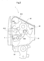
- Fig. 2 indicates the vehicle door lock apparatus of the embodiment viewed from right side in Fig. 1 .
- Fig. 3 is a view explaining the shape of an active lever according to the embodiment of the invention.
- Fig. 4 is a view similar to Fig. 3 , but showing a conventional active lever.
- Fig. 5 is an explanatory view of an operation of a conventional door lock apparatus.
- Fig. 6 is an explanatory view of the door lock apparatus according to the embodiment of the invention, explaining the operation of a non-manipulability condition of the unlocking operation.
- Fig. 1 is a side view of the vehicle door lock apparatus to be accommodated in a vehicle door according to an embodiment of the invention.
- the vehicle door lock apparatus 1 for vehicles is formed by a lift lever 2 supported by a housing 80 ( Fig. 2 ), an opening link 3, an opening lever 4, an active lever 5 and a cancelling lever 7.
- Fig. 1 shows the door lock apparatus viewed from inside of the vehicle door under the opening link 3 being driven by the opening lever 4 while the locking operation is being changed to unlocking operation.
- Fig. 2 shows the door lock apparatus 1 for vehicles seen from the right side in Fig. 1 and indicates the lift lever 2, a striker and a latch mechanism (latch 82 and pawl 83).
- the lift lever 2 is provided at the vehicle door and is used for releasing an engagement between the rod shaped striker 81 provided at the vehicle body and the pawl 83 forming a part of the latch mechanism.
- the lift lever 2 is rotatably supported on the housing 80 and connected to the pawl 83 of the latch mechanism.
- the pawl 83 engages with a latch 82 forming a part of the latch mechanism which is in engagement with the rod shaped striker 81.
- the latch 82 includes projections 820 and 821.
- the lift lever 2 is biased in a counterclockwise direction as viewed in Fig. 2 by a biasing member (not shown) and held to the original position.
- the pawl 83 is rotated in a clockwise direction to release the engagement between the latch 82 and the pawl 83.
- the latch 82 released from the engagement, is rotated in a clockwise direction as viewed in Fig. 2 to a released position 82A as indicated with two-dotted chain line.
- the striker 81 is in a position 81A and is releasable in the left direction.
- the door can be opened.
- the opening link 3 is oblong rod-shaped member and disposed within the vicinity of the lift lever 2.
- the opening link 3 is supported by the opening lever 4 and the active lever 5.
- An engaging hole 31 is provided at one end of the opening link 3.
- the engaging hole 31 is of oblong (elongated) shape having a constricted portion at the central portion thereof.
- An engaging lever 44 is formed on the opening lever 4 and inserted into and engaged with the engaging hole 31.
- a guide pin 32 is provided at and projected from the opening link 3 functioning as an engaging projection portion. As is shown in Fig. 1 , the guide pin 32 is inserted into a guide hole 6 formed on the active lever 5 and engaged therewith.
- the other end of the opening link 3 is provided with a pushing portion 33.
- the opening lever 4 is provided in a width direction relative to the door and rotatably supported by the housing 80.
- the opening lever 4 has a pivot hole 41 at the central portion thereof and pivotally supported by the housing 80 of the door lock apparatus 1 at the pivot hole 41.
- the opening lever 4 further includes an outwardly extending arm extending from the central portion and an inwardly extending arm extending from the central portion and arranged opposite to the outwardly extending arm. As shown in Fig. 1 , an end portion of the outwardly extending arm is bent in approximately horizontal direction to form one side portion 42a having a connecting hole 42 therein.
- the connecting hole 42 is connected to a door outside handle 100 for opening the door via connecting means. When the outside handle 100 is manually operated, the connecting hole 42 is pushed down as viewed in Fig. 1 .
- the inwardly extending arm of the opening lever 4 is branched to two branch portions in a vertical direction at one end and one of the branch portions is approximately bent in a horizontal direction to form a portion to be pressed 43 and the other branch portion serves as an engaging lever portion 44.
- the engaging lever portion 44 is inserted into the engaging hole 31 of the opening link 3 and engaged therewith. Accordingly, the engaging lever portion 44 can actuate the opening link 3 in an upward direction as viewed in Fig. 1 .
- the engaging lever portion 44 serves as a fulcrum point for rotation of the opening link 3 between an upright position as indicated by reference (1) in Fig. 5 and an inclined position as indicated by reference (2) in Fig. 5 .
- the portion to be pressed 43 formed at the opening lever 4 is connected to an inside handle 101 via connecting means, such as cables.
- the portion to be pressed 43 is pushed upwardly as viewed in fig. 1 .
- the opening lever 4 is held at the original position thereof by a vertically downwardly rotational movement of the engaging lever portion 44 by the biasing force of a biasing means (not shown) as viewed in Fig. 1 .
- the engaging lever portion 44 moves upward to push the opening link 3 upwardly only when the outside handle 100 or the inside handle 101 is manually operated.
- the active lever 5 is rotatably supported by the housing 80 for operating the opening link 3 to switch over from the unlocking condition to locking condition.
- the unlocking condition means the condition that the opening link 3 can push the lift lever 2
- the locking condition means the condition that the opening link 3 cannot push the lift lever 2, in other words, the opening link 3 is positioned where the lever cannot be actuated.
- Fig. 3 indicates the shape of the active lever 5 which will be explained with reference to Fig. 3 .
- the active lever 5 has a pivot hole 51 and the pivot hole 51 of the active lever 5 is rotatably supported by the housing 80 in a direction indicated by arrows CA and CB.
- the active lever 5 includes a first arm 52, a second arm 54 and a third arm 56 formed integrally.
- the first arm 52 is provided with a connecting hole 53 at the tip end thereof.
- the connecting hole 53 is connected to a locking knob 103 provided inside of the door via a connecting means such as rod member or the like.
- the second arm 54 of the active lever 5 is provided with a contact portion 55 formed at the tip end thereof and is connected to a locking device 104 provided outside of the door.
- the active lever 5 can be rotated by operation of the locking knob 103 from the inside of the door, by operation of the locking device 104 outside of the door using a key.
- An engaging groove 57 is formed on the third arm 56 of the active lever 5 at an upper left side portion as viewed in Fig. 1 and is engageable with an actuator 105 driven by the electric motor.
- the electric motor of the actuator 105 is remote-controlled by an automatic locking/unlocking system, for example, a smart entry system. Accordingly, when the electric motor (actuator 105) is actuated in the automatic locking/unlocking system, the active lever 5 can swing centering on the pivot hole 51. Thus, the active lever 5 can be operated by any of the locking knob 103 provided inside of the door, the locking device 104 provided outside of the door and the electric motor (actuator 105). Then the active lever 5 is rotated in a clockwise direction (in the arrow CA direction) around the pivot hole 51 by the unlocking operation and in a counterclockwise direction (in the arrow CB direction) by the locking operation. The active lever 5 is urged to the locking condition position and the unlocking condition position to keep each position by a biasing means (not shown).
- a biasing means not shown.
- the third arm 56 of the active lever 5 has a guide hole 6 which corresponds to the one-way driving portion in claim of the invention.
- Outer brim of the guide hole 6 is formed by a sliding brim portion 61 extending in an up/down direction as viewed in Fig. 3 , a pushing brim portion 62 expanding consecutively from one end of the sliding brim portion 61 in upward direction, and a return brim portion 63 extending consecutively from the pushing brim portion 62 and extending from an upper end which expands towards left as viewed in the drawing to the other end of the sliding brim portion 61 with an inclination.
- the guide pin 32 of the opening link 3 is inserted into the guide hole 6. Inside of the guide hole 6 is expanded to have a diameter larger than that of the guide pin 32 and a free movement range 64 is provided around the center of the hole.
- the width of the guide hole 6 is indicated as X in the rotational direction (directions indicated with arrows CA and CB) of the active lever 5 centering on the pivot hole 51 and the length of the guide hole 6 is indicated as Y in a direction crossing over the rotational direction of the active lever 5.
- the guide hole 6 is more elongated in a rotational direction (directions indicated with arrows CA and CB) of the active lever 5 than that of an elongated hole 96 ( Fig. 4 ) of an active lever 95 used in a conventional door lock apparatus, which will be explained later.
- the guide pin 32 of the opening link 3 is movable in the length direction Y and in the width direction X.
- the width X in the free movement range 64 is set to be larger than the diameter of the guide pin 32.
- the canceling lever 7 corresponds to the pushing mechanism and is a member, which pushes the left side of the opening link 3 in a right direction as viewed in fig. 1 .
- the canceling lever 7 as the pushing mechanism pushes one side surface of the opening link 3 in an arrow H direction to move the guide pin 32 of the opening link 3 to be in a sliding contact with the sliding brim portion 61 of the guide hole 6 of the active lever 5.
- the cancelling lever 7 includes a pivot hole 71 at the center thereof.
- the cancelling lever 7 is shaped as a bent member.
- the cancelling lever 7 is formed with a pushing portion 72.
- the pushing portion 72 is always urged by a biasing member 73 to push the left side surface of the opening link 3 towards right (in the arrow H direction).
- the biasing force of the biasing member 73 is set to be smaller than the biasing force of the biasing means for biasing the active lever 5.
- the conventional door lock apparatus 9 has the same structure and components of the door lock apparatus of the embodiment and numerals are commonly referenced, except the structure of the active lever 5.
- Fig. 4 indicates the active lever 95 used in the conventional door lock apparatus 9.
- an elongated slit shaped hole 96 with a narrower width diameter is provided.
- the elongated hole 96 is formed extending in an up/down direction as viewed in Fig. 4 and includes a right side brim portion as viewed in Fig. 4 formed at the same position with the sliding brim portion 61 of the embodiment of the invention.
- the guide hole 6 of the embodiment is formed by expanding the elongated hole 96 to the left.
- the width of hole 96 in right and left direction corresponds to the length of diameter of the guide pin 32.
- the guide pin 32 is guided only in an up/down direction (towards elongated direction) within the elongated hole 96.
- the guide pin 32 cannot move in a width direction.
- Fig. 5 shows an operation explanation view of the conventional door lock apparatus 9.
- the bold lines are illustrated in an overlapping manner.
- the unlocking condition is indicated as condition (1) and the locking condition is indicated as condition (2).
- the reference numeral (3) indicates the condition where the unlocking operation by door opening handle is carried out while the unlocking operation is being carried out from the locking condition to the unlocking condition.
- the reference numeral (4) indicates the non-manipulability condition of the unlocking operation.
- the active lever 5 is rotated around the pivot hole 51 in a clockwise direction (in the arrow CA direction) and the guide pin 32 is moved to the right (arrow CA direction) by the elongated hole 96.
- the opening link 3 is positioned upright.
- the opening link 3 moves upward by the opening lever 4.
- the guide pin 32 is guided by the elongated hole 96 in an upright direction to move the opening link 3 directly above as indicated with an arrow A direction.
- the pushing portion 33 of the opening link 3 pushes the lift lever 2 up to release the engagement between the latch 82 and the pawl 83 and the door is ready for open.
- the active lever 95 is rotated in a counterclockwise direction (arrow CB direction) around the pivot hole 51.
- the guide pin 32 is moved to the left (arrow CB direction) by the elongated hole 96 and the opening link 3 is in a tilted position not in upright position.
- the elongated hole 96 is also in a tilted position and under this condition when the door opening handle is operated to open the door, the opening link 3 moves upward by the opening lever 4.
- the guide pin 32 is guided towards the upward left (as viewed in Fig. 5 (2) condition). Accordingly, the opening link 3 is operated to move upward with an inclination as viewed in an arrow B.
- the opening link 3 does not contact with the lift lever 2.
- the latch 82 and the pawl 83 keep the engagement therebetween.
- the door is not opened.
- the active lever 95 receives a biasing force in a clockwise direction by the cancelling lever 7 via the guide pin 32 of the opening lever 3. Since the biasing force of the biasing member 73 of the cancelling lever 7 is set to be smaller than the biasing force by the biasing means of the active lever 95, the active lever 95 can keep its locking condition position.
- the actuator 105 is operated for a predetermined period for rotating the active lever 95 around the pivot hole 51 in a clockwise direction (arrow CA direction) to move to the unlocking condition (1) in Fig. 5 .
- the opening link 3 becomes upright position and the door is under unlocking condition to be able to open the door.
- the opening link 3 may be brought into contact with the lift lever 2 from the side direction. This may fall into a non-manipulability condition of unlocking operation.
- the cancelling lever 7 is always urging the opening link 3 to the right as viewed in Fig. 6 (in the arrow H direction in condition (1) of Fig. 6 ). For this reason, the guide pin 32 of the opening link 3 is pushed and in contact with the right side of the sliding brim portion 61 of the guide hole 6.
- the opening link 3 is pushed upward and then the guide pin 32 slides along the sliding brim portion 61 of the guide hole 6 to move upward.
- the opening link 3 is operated as similar to the conventional device 9 indicated in (1) and (2) in Fig. 5 .
- the active lever 5 is rotated centering on the pivot hole 51 in a clockwise direction (arrow F direction of Fig. 6 ) to drive the opening link 3 to move from the locking condition to unlocking condition.
- the sliding brim portion 61 of the guide hole 6 formed on the active lever 5 is operated preceding the operation of guide pin 32.
- the active lever 5 is rotated in a clockwise direction (arrow F direction, unlocking direction), keeping the guide pin 32 of the opening link 3 to the position.
- the guide pin 32 can be relatively displaceable in a width X direction ( Fig. 3 ) of the guide hole 6 relative to the active lever 5. Accordingly, the guide pin 32 is not operated by the wall forming the guide hole 6.
- the guide pin 32 is freely movable within the space defined by the free movement range 64 as long as no force is applied to the opening link 3 from any other members.
- a biasing force for returning the opening lever 4 to its original position and a pushing force by the cancelling lever 7 are applied to the opening link 3. Accordingly, in Fig. 6 , the opening link 3 is pushed both in downward direction and rightward direction and therefore, the guide pin 32 of the opening link 3 is driven to the unlocking condition, stopping at the lower portion of the sliding brim portion 61 of the guide hole 6.
- Fig. 6 shows the avoidance of the non-manipulability condition for unlocking operation of the door lock apparatus 1 according to the embodiment.
- the condition (1) in Fig. 6 shows the condition in which the door opening handle is manually operated on the way of unlocking operation.
- the condition (2) in Fig. 6 shows the unlocking condition after avoiding the non-manipulability condition for unlocking operation.
- the opening link 3 is driven to move upward by the opening lever 4 and then the opening link 3 is driven to the right by the active lever 5.
- the operation that the opening link 3 makes the contact with the lift lever 2 from side direction is the same with the conventional door lock apparatus.
- the guide hole 6 formed on the active lever 5 in the door lock apparatus 1 of the embodiment is relatively expanded in the rotational direction (the arrow CA direction and CB direction) relative to the active lever 5 compared to the corresponding hole (elongated hole 96 as seen in Fig. 4 ) of the conventional structure.
- the guide pin 32 of the opening link 3 is freely movable within the free movement range 64 formed at the inside of the guide hole 6 without being restrained by the guide hole 6 of the active lever 5.
- the active lever 5 is rotated in a clockwise direction shown with the arrow F until reaching the final position.
- the active lever 5 can be moved from the locking condition position to the unlocking condition position without having any problems.
- the guide pin 32 of the opening link 3 is moved downward driven by the two forces as freely moving in the space defined by the free movement range 64 of the guide hole 6 of the active lever 5 or sliding along the returning brim portion 63 of the guide hole 6.
- the opening link 3 returns to the original position located at the lower side.
- the opening link 3 is finally pushed by the pushing portion 72 of the cancelling lever 7 in the arrow H direction and the guide pin 32 of the opening link 3 becomes in contact with the sliding brim portion 61.
- the opening link 3 positions upright at the lower side of the lift lever 2 and returns to the unlocking condition. In other words, the non-manipulability condition for unlocking operation of the door lock apparatus 1 can be avoided.
- the conventional elongated hole 96 of the active lever 5 into which the guide pin 32 of the opening link 3 is inserted is expanded along the rotation direction of the active lever 5 (in the arrow F direction and opposite to the arrow F direction, i.e., in the arrows CA and CB directions) so that the width of the hole is enlarged to form the guide hole 6.
- the non-manipulability condition for the unlocking operation can be avoided.
- the portion of the guide hole 6, in which the free movement range 64 is formed in the rotation direction of the active lever may, be formed only at the portion where the guide pin 32 is positioned within the guide hole 6, when the opening link 3 is driven upwardly by the opening lever 4.
- the lower side portion of the guide hole 6 is not necessarily expanded to form the free movement range 64.
- a guide hole 6 functions as an element of a so-called double pull function which achieves both unlocking and door-opening operations by operation of the inside door handle 101.
- This invention can be utilized for the vehicle door lock apparatus.
Landscapes
- Lock And Its Accessories (AREA)
Abstract
The door lock apparatus includes a lift lever 2 for pushing a latch mechanism provided at the door and engaged with a striker provided at the vehicle body and enabling to release the engagement of the latch mechanism with the striker, an opening link 3 for pushing the lift lever 2 by contacting therewith, an opening lever 4 operated by a handle for pushing the lift lever 2 by the opening link 3 by driving the same and an active lever for driving the opening link 3 to a lever non-drivable position where the pushing of the lift lever by the opening link 3 is disenabled. One-way driving portion 6 of the active lever 5 drives the opening link 3 only in a direction towards the lever non-drivable position side and restricts the driving in the opposite direction.
Description
- This invention relates to a door lock apparatus for vehicles and more particularly, to a door lock apparatus for vehicles which prevents non-manipulability condition of unlocking operation.
- As an example of a vehicle door lock apparatus for locking a vehicle door to a vehicle body is disclosed in the
patent document 1. The door lock apparatus disclosed in the patent document includes a striker (member to be hooked) provided at the vehicle body side and a latch mechanism (latch and pawl) provided at the vehicle door side and the door is kept in a closed condition by engaging a latch of the latch mechanism with the striker. A lift lever is provided in order to have the latch mechanism to be in a releasable condition from the latched condition. Further, an opening link is provided as a member for pushing the lift lever. Further, an opening member is disposed for transmitting a door handle operation force to the opening link. Further, the door lock apparatus has an unlocking condition in which the lift lever is operable and a locking condition in which the lift lever is not operable by switching over the position of the opening link by an active lever. The active lever is generally operated by operating a locking knob provided in the inside of the door or by key operation from the outside of the door. However, the active lever is also operated by an actuator including an electric motor as a drive source. - Recently, a smart entry system for operating a locking operation or an unlocking operation of the door lock apparatus by remote- and electrical-controlling or an intelligent key system in which the locking and unlocking operations are automatically performed are becoming popular. In the smart entry system, a key with a wireless transmitting function is used and when a driver, owning the key with him or her, approaches the vehicle, or when a driver with the key just pushes a button provided on the vehicle, an unlocking command is transmitted to the vehicle side by radio. On the other hand, the vehicle side is provided with a wireless receiving function and when the unlocking command is received at the vehicle side, the actuator is activated and the active lever changes the condition of the door lock apparatus from locking to unlocking condition. Then, the driver approaches from a distance to the vehicle door, the door can be opened by just operating a door opening handle. This facilitates the door opening operation using the key.
Patent Document 1:JA 2007-100318A - When an automatic locking system is adapted to the door lock apparatus disclosed in the
patent document 1, for example, the door lock apparatus sometimes, but not very often becomes in trouble with incapability or non-manipulability of opening operation. This incapability or non-manipulability of opening operation occurs when the driver or a passenger of the vehicle manually operates the door handle of the vehicle door while the automatic unlocking operation is being performed by switching over the locking condition to unlocking condition by the actuator. In detail, the opening link is driven during the transition from the locking condition to the unlocking condition, and accordingly, the transition to the unlocking condition is interfered by the lift lever. After such interference occurs, the switching over operation from the lock condition to the unlocking condition of the opening link for door opening operation cannot be performed and the door lock apparatus falls in a non-manipulability condition of unlocking operation, a so-called in "a state of panic". - Such non-manipulability condition of unlocking operation can be restored by re-locking operation or unlocking operation manually or using the automatic unlocking system to drive the active lever. However, such operation is cumbersome and accordingly, in order to avoid such non-manipulability condition, the opening link or active lever is divided into several pieces and then connected together by spring or the like. This, however, increases the number of part and the structure becomes complicated and it may lead to increase of manufacturing cost.
- The present invention was made in consideration with the above problems and the object of the invention is to provide a door lock apparatus for vehicles which can avoid an occurrence of non-manipulability condition of the unlocking operation without major changing of the structure and without adding any additional parts.
- The vehicle door lock apparatus of this invention made for solving the above problems is characterized in that the door lock apparatus includes a lift lever provided at a vehicle door and capable of releasing an engagement of a latch mechanism with a striker provided at a vehicle body,
an opening link for pushing the lift lever by contacting therewith, an opening lever for pushing the lift lever by the opening link by actuating the same and an active lever for driving the opening link to a lever non-drivable position for disenabling the pushing of the lift lever by the opening link, wherein the active lever includes a one-way driving portion for driving the opening lever only in a direction towards the lever non-drivable position and disenabling the driving of the opening link in the opposite direction when the opening link is driven by the opening lever. -
Fig. 1 is a side view of a vehicle door lock according to an embodiment of the invention. -
Fig. 2 indicates the vehicle door lock apparatus of the embodiment viewed from right side inFig. 1 . -
Fig. 3 is a view explaining the shape of an active lever according to the embodiment of the invention. -
Fig. 4 is a view similar toFig. 3 , but showing a conventional active lever. -
Fig. 5 is an explanatory view of an operation of a conventional door lock apparatus. -
Fig. 6 is an explanatory view of the door lock apparatus according to the embodiment of the invention, explaining the operation of a non-manipulability condition of the unlocking operation. - The best mode embodiments of the invention will be explained hereinafter with reference to the attached drawings of
Figs. 1 through 6 .Fig. 1 is a side view of the vehicle door lock apparatus to be accommodated in a vehicle door according to an embodiment of the invention. The vehicledoor lock apparatus 1 for vehicles is formed by alift lever 2 supported by a housing 80 (Fig. 2 ), anopening link 3, anopening lever 4, anactive lever 5 and acancelling lever 7.
Fig. 1 shows the door lock apparatus viewed from inside of the vehicle door under theopening link 3 being driven by theopening lever 4 while the locking operation is being changed to unlocking operation.
Fig. 2 shows thedoor lock apparatus 1 for vehicles seen from the right side inFig. 1 and indicates thelift lever 2, a striker and a latch mechanism (latch 82 and pawl 83). - As shown in
Fig. 2 , thelift lever 2 is provided at the vehicle door and is used for releasing an engagement between the rod shapedstriker 81 provided at the vehicle body and thepawl 83 forming a part of the latch mechanism. Thelift lever 2 is rotatably supported on thehousing 80 and connected to thepawl 83 of the latch mechanism. Thepawl 83 engages with alatch 82 forming a part of the latch mechanism which is in engagement with the rod shapedstriker 81. Thelatch 82 includesprojections - The
lift lever 2 is biased in a counterclockwise direction as viewed inFig. 2 by a biasing member (not shown) and held to the original position. When thelift lever 2 is pushed by theopening link 3, thepawl 83 is rotated in a clockwise direction to release the engagement between thelatch 82 and thepawl 83. Thus the door becomes in openable (opening possible) condition. Thelatch 82, released from the engagement, is rotated in a clockwise direction as viewed inFig. 2 to a releasedposition 82A as indicated with two-dotted chain line. Under this situation, thestriker 81 is in aposition 81A and is releasable in the left direction. Thus the door can be opened. - As shown in
Fig. 1 , theopening link 3 is oblong rod-shaped member and disposed within the vicinity of thelift lever 2. Theopening link 3 is supported by theopening lever 4 and theactive lever 5. Anengaging hole 31 is provided at one end of theopening link 3. Theengaging hole 31 is of oblong (elongated) shape having a constricted portion at the central portion thereof. Anengaging lever 44 is formed on theopening lever 4 and inserted into and engaged with theengaging hole 31. Aguide pin 32 is provided at and projected from theopening link 3 functioning as an engaging projection portion. As is shown inFig. 1 , theguide pin 32 is inserted into aguide hole 6 formed on theactive lever 5 and engaged therewith. The other end of theopening link 3 is provided with a pushingportion 33. - The
opening lever 4 is provided in a width direction relative to the door and rotatably supported by thehousing 80. In more detail, theopening lever 4 has apivot hole 41 at the central portion thereof and pivotally supported by thehousing 80 of thedoor lock apparatus 1 at thepivot hole 41. Theopening lever 4 further includes an outwardly extending arm extending from the central portion and an inwardly extending arm extending from the central portion and arranged opposite to the outwardly extending arm. As shown inFig. 1 , an end portion of the outwardly extending arm is bent in approximately horizontal direction to form oneside portion 42a having a connectinghole 42 therein. The connectinghole 42 is connected to a dooroutside handle 100 for opening the door via connecting means. When theoutside handle 100 is manually operated, the connectinghole 42 is pushed down as viewed inFig. 1 . - The inwardly extending arm of the
opening lever 4 is branched to two branch portions in a vertical direction at one end and one of the branch portions is approximately bent in a horizontal direction to form a portion to be pressed 43 and the other branch portion serves as an engaginglever portion 44. The engaginglever portion 44 is inserted into the engaginghole 31 of theopening link 3 and engaged therewith. Accordingly, the engaginglever portion 44 can actuate theopening link 3 in an upward direction as viewed inFig. 1 . And further, the engaginglever portion 44 serves as a fulcrum point for rotation of theopening link 3 between an upright position as indicated by reference (1) inFig. 5 and an inclined position as indicated by reference (2) inFig. 5 . The portion to be pressed 43 formed at theopening lever 4 is connected to aninside handle 101 via connecting means, such as cables. - When the
inside handle 101 for door opening is operated manually, the portion to be pressed 43 is pushed upwardly as viewed infig. 1 . Theopening lever 4 is held at the original position thereof by a vertically downwardly rotational movement of the engaginglever portion 44 by the biasing force of a biasing means (not shown) as viewed inFig. 1 . The engaginglever portion 44 moves upward to push theopening link 3 upwardly only when theoutside handle 100 or theinside handle 101 is manually operated. - As shown in
Fig. 1 , theactive lever 5 is rotatably supported by thehousing 80 for operating theopening link 3 to switch over from the unlocking condition to locking condition. It is noted here that the unlocking condition means the condition that theopening link 3 can push thelift lever 2 and that the locking condition means the condition that theopening link 3 cannot push thelift lever 2, in other words, theopening link 3 is positioned where the lever cannot be actuated. -
Fig. 3 indicates the shape of theactive lever 5 which will be explained with reference toFig. 3 . Theactive lever 5 has apivot hole 51 and thepivot hole 51 of theactive lever 5 is rotatably supported by thehousing 80 in a direction indicated by arrows CA and CB. Theactive lever 5 includes afirst arm 52, asecond arm 54 and athird arm 56 formed integrally. Thefirst arm 52 is provided with a connectinghole 53 at the tip end thereof. The connectinghole 53 is connected to a lockingknob 103 provided inside of the door via a connecting means such as rod member or the like. Thesecond arm 54 of theactive lever 5 is provided with acontact portion 55 formed at the tip end thereof and is connected to alocking device 104 provided outside of the door. Accordingly, theactive lever 5 can be rotated by operation of the lockingknob 103 from the inside of the door, by operation of thelocking device 104 outside of the door using a key. An engaginggroove 57 is formed on thethird arm 56 of theactive lever 5 at an upper left side portion as viewed inFig. 1 and is engageable with anactuator 105 driven by the electric motor. - The electric motor of the
actuator 105 is remote-controlled by an automatic locking/unlocking system, for example, a smart entry system. Accordingly, when the electric motor (actuator 105) is actuated in the automatic locking/unlocking system, theactive lever 5 can swing centering on thepivot hole 51. Thus, theactive lever 5 can be operated by any of the lockingknob 103 provided inside of the door, thelocking device 104 provided outside of the door and the electric motor (actuator 105). Then theactive lever 5 is rotated in a clockwise direction (in the arrow CA direction) around thepivot hole 51 by the unlocking operation and in a counterclockwise direction (in the arrow CB direction) by the locking operation. Theactive lever 5 is urged to the locking condition position and the unlocking condition position to keep each position by a biasing means (not shown). - As shown in
Fig. 3 , thethird arm 56 of theactive lever 5 has aguide hole 6 which corresponds to the one-way driving portion in claim of the invention. Outer brim of theguide hole 6 is formed by a slidingbrim portion 61 extending in an up/down direction as viewed inFig. 3 , a pushingbrim portion 62 expanding consecutively from one end of the slidingbrim portion 61 in upward direction, and areturn brim portion 63 extending consecutively from the pushingbrim portion 62 and extending from an upper end which expands towards left as viewed in the drawing to the other end of the slidingbrim portion 61 with an inclination. Theguide pin 32 of theopening link 3 is inserted into theguide hole 6. Inside of theguide hole 6 is expanded to have a diameter larger than that of theguide pin 32 and afree movement range 64 is provided around the center of the hole. - As shown in
Fig. 3 , the width of theguide hole 6 is indicated as X in the rotational direction (directions indicated with arrows CA and CB) of theactive lever 5 centering on thepivot hole 51 and the length of theguide hole 6 is indicated as Y in a direction crossing over the rotational direction of theactive lever 5. Theguide hole 6 is more elongated in a rotational direction (directions indicated with arrows CA and CB) of theactive lever 5 than that of an elongated hole 96 (Fig. 4 ) of anactive lever 95 used in a conventional door lock apparatus, which will be explained later. Accordingly, within a space defined by thefree movement range 64, theguide pin 32 of theopening link 3 is movable in the length direction Y and in the width direction X. The width X in thefree movement range 64 is set to be larger than the diameter of theguide pin 32. - As shown in
Fig. 1 , the cancelinglever 7 corresponds to the pushing mechanism and is a member, which pushes the left side of theopening link 3 in a right direction as viewed infig. 1 . The cancelinglever 7 as the pushing mechanism pushes one side surface of theopening link 3 in an arrow H direction to move theguide pin 32 of theopening link 3 to be in a sliding contact with the slidingbrim portion 61 of theguide hole 6 of theactive lever 5. As shown inFig. 1 , the cancellinglever 7 includes apivot hole 71 at the center thereof. The cancellinglever 7 is shaped as a bent member. - The cancelling
lever 7 is formed with a pushingportion 72. The pushingportion 72 is always urged by a biasingmember 73 to push the left side surface of theopening link 3 towards right (in the arrow H direction). When the door is closed under the locking condition, the cancellinglever 7 cancels the locking condition to resume the unlocking condition by thelift lever 2. The biasing force of the biasingmember 73 is set to be smaller than the biasing force of the biasing means for biasing theactive lever 5. - Before explaining the operation of the door lock apparatus according to the embodiment, the structure and operation of the conventional door lock apparatus, as well as the non-manipulability condition of the unlocking operation will be explained first. The conventional
door lock apparatus 9 has the same structure and components of the door lock apparatus of the embodiment and numerals are commonly referenced, except the structure of theactive lever 5.Fig. 4 indicates theactive lever 95 used in the conventionaldoor lock apparatus 9. Instead of using theguide hole 6 as used in the invention, an elongated slit shapedhole 96 with a narrower width diameter is provided. - As shown in
Fig. 4 , theelongated hole 96 is formed extending in an up/down direction as viewed inFig. 4 and includes a right side brim portion as viewed inFig. 4 formed at the same position with the slidingbrim portion 61 of the embodiment of the invention. In practice, theguide hole 6 of the embodiment is formed by expanding theelongated hole 96 to the left. The width ofhole 96 in right and left direction corresponds to the length of diameter of theguide pin 32. In other words, theguide pin 32 is guided only in an up/down direction (towards elongated direction) within theelongated hole 96. Theguide pin 32 cannot move in a width direction. When theactive lever 95 is rotated and theelongated hole 96 is accordingly rotated in the right/left direction as viewed infig. 4 , theguide pin 32 is rotated in both right and left directions due to the engagement with theelongated hole 96. -
Fig. 5 shows an operation explanation view of the conventionaldoor lock apparatus 9. For better understanding, the bold lines are illustrated in an overlapping manner. InFig. 5 , the unlocking condition is indicated as condition (1) and the locking condition is indicated as condition (2). The reference numeral (3) indicates the condition where the unlocking operation by door opening handle is carried out while the unlocking operation is being carried out from the locking condition to the unlocking condition. The reference numeral (4) indicates the non-manipulability condition of the unlocking operation. - Under the unlocking condition (1) indicated in
Fig. 5 , theactive lever 5 is rotated around thepivot hole 51 in a clockwise direction (in the arrow CA direction) and theguide pin 32 is moved to the right (arrow CA direction) by theelongated hole 96. Theopening link 3 is positioned upright. When the door opening handle is operated for opening the door under theopening link 3 being in upright position, theopening link 3 moves upward by theopening lever 4. Then theguide pin 32 is guided by theelongated hole 96 in an upright direction to move theopening link 3 directly above as indicated with an arrow A direction. Then the pushingportion 33 of theopening link 3 pushes thelift lever 2 up to release the engagement between thelatch 82 and thepawl 83 and the door is ready for open. - Under the locking condition (2) in
Fig. 5 , theactive lever 95 is rotated in a counterclockwise direction (arrow CB direction) around thepivot hole 51. As the result, theguide pin 32 is moved to the left (arrow CB direction) by theelongated hole 96 and theopening link 3 is in a tilted position not in upright position. Under the locking condition (2) inFig. 5 , theelongated hole 96 is also in a tilted position and under this condition when the door opening handle is operated to open the door, theopening link 3 moves upward by theopening lever 4. Theguide pin 32 is guided towards the upward left (as viewed inFig. 5 (2) condition). Accordingly, theopening link 3 is operated to move upward with an inclination as viewed in an arrow B. Thus theopening link 3 does not contact with thelift lever 2. In other words, thelatch 82 and thepawl 83 keep the engagement therebetween. Thus the door is not opened. - The
active lever 95 receives a biasing force in a clockwise direction by the cancellinglever 7 via theguide pin 32 of theopening lever 3. Since the biasing force of the biasingmember 73 of the cancellinglever 7 is set to be smaller than the biasing force by the biasing means of theactive lever 95, theactive lever 95 can keep its locking condition position. - Next, in the locking condition (2) of
Fig. 5 according to the conventionaldoor lock apparatus 9, the operation of the unlocking condition to the locking condition by receipt of command from the automatic locking/unlocking system will be explained hereinafter. In the automatic locking/unlocking system, usually theactuator 105 is operated for a predetermined period for rotating theactive lever 95 around thepivot hole 51 in a clockwise direction (arrow CA direction) to move to the unlocking condition (1) inFig. 5 . Theopening link 3 becomes upright position and the door is under unlocking condition to be able to open the door. - However, in
Fig. 5 , when the door opening handle is manually operated on the way to the locking condition (1) from the condition (2), the condition may be moved to the condition (3). Under the condition (3) inFig. 5 , the rotation movement of theactive lever 95 in a clockwise direction indicated with the arrow C and the driving operation of the opening lever 4 (door handle operation) indicated with the arrow D are applied to theopening link 3 in an overlapping manner. Then theopening link 3 driven to move upwardly with an inclination is pushed by theactive lever 95 to be driven to the right. - As the result, as shown in the condition (4) in
Fig. 5 , theopening link 3 may be brought into contact with thelift lever 2 from the side direction. This may fall into a non-manipulability condition of unlocking operation. - Next, the operation of the
door lock apparatus 1 for vehicles according to the embodiment of the invention will be explained hereinafter. First, the situation that the door opening handle is operated when thedoor lock apparatus 1 is under the locking condition or unlocking condition will be explained. As explained above, according to thedoor lock apparatus 1 of the invention, the cancellinglever 7 is always urging theopening link 3 to the right as viewed inFig. 6 (in the arrow H direction in condition (1) ofFig. 6 ). For this reason, theguide pin 32 of theopening link 3 is pushed and in contact with the right side of the slidingbrim portion 61 of theguide hole 6. Accordingly, by the operation of the door opening handle, theopening link 3 is pushed upward and then theguide pin 32 slides along the slidingbrim portion 61 of theguide hole 6 to move upward. Thus, theopening link 3 is operated as similar to theconventional device 9 indicated in (1) and (2) inFig. 5 . - Next, the locking operation of the
door lock apparatus 1 from unlocking condition to the locking condition will be explained. This locking operation is carried out similar to the locking operation of theconventional device 9. The right side slidingbrim portion 61 of theguide hole 6 formed on theactive lever 5 pushes theguide pin 32 of theopening link 3 to rotate in a counterclockwise direction (arrow CB direction). In other words, the guide hole 6 (in detail the right side sliding brim portion 61) as the one-way driving portion enables the rotation in a counterclockwise direction (arrow CB direction) as is the case of the conventionaldoor lock apparatus 9. - Next, the unlocking operation of the
door lock apparatus 1 from locking condition to the unlocking condition will be explained. This unlocking operation is carried out different from the unlocking operation of theconventional device 9. - In other words, the unlocking operation from the locking condition to the unlocking condition according to the
door lock apparatus 1, theactive lever 5 is rotated centering on thepivot hole 51 in a clockwise direction (arrow F direction ofFig. 6 ) to drive theopening link 3 to move from the locking condition to unlocking condition. At this time, the slidingbrim portion 61 of theguide hole 6 formed on theactive lever 5 is operated preceding the operation ofguide pin 32. - In other words, the
active lever 5 is rotated in a clockwise direction (arrow F direction, unlocking direction), keeping theguide pin 32 of theopening link 3 to the position. In this case, theguide pin 32 can be relatively displaceable in a width X direction (Fig. 3 ) of theguide hole 6 relative to theactive lever 5. Accordingly, theguide pin 32 is not operated by the wall forming theguide hole 6. Theguide pin 32 is freely movable within the space defined by thefree movement range 64 as long as no force is applied to theopening link 3 from any other members. - A biasing force for returning the
opening lever 4 to its original position and a pushing force by the cancellinglever 7 are applied to theopening link 3. Accordingly, inFig. 6 , theopening link 3 is pushed both in downward direction and rightward direction and therefore, theguide pin 32 of theopening link 3 is driven to the unlocking condition, stopping at the lower portion of the slidingbrim portion 61 of theguide hole 6. - Finally, the operation of the door opening handle being operated while the unlocking operation from the locking condition to the unlocking condition is being carried out in the automatic locking /unlocking system for the
door lock apparatus 1 of the embodiment will be explained. In other words, the case in which the unlocking operation by the automatic locking/unlocking system and the driving operation from the opening lever 4 (manual operation by door opening handle) are carried out to operate theopening link 3 with the overlapped manner will be explained. -
Fig. 6 shows the avoidance of the non-manipulability condition for unlocking operation of thedoor lock apparatus 1 according to the embodiment. The condition (1) inFig. 6 shows the condition in which the door opening handle is manually operated on the way of unlocking operation. The condition (2) inFig. 6 shows the unlocking condition after avoiding the non-manipulability condition for unlocking operation. According to thedoor lock apparatus 1 of the embodiment, theopening link 3 is driven to move upward by theopening lever 4 and then theopening link 3 is driven to the right by theactive lever 5. The operation that theopening link 3 makes the contact with thelift lever 2 from side direction is the same with the conventional door lock apparatus. - However, the
guide hole 6 formed on theactive lever 5 in thedoor lock apparatus 1 of the embodiment is relatively expanded in the rotational direction (the arrow CA direction and CB direction) relative to theactive lever 5 compared to the corresponding hole (elongatedhole 96 as seen inFig. 4 ) of the conventional structure. For this reason, theguide pin 32 of theopening link 3 is freely movable within thefree movement range 64 formed at the inside of theguide hole 6 without being restrained by theguide hole 6 of theactive lever 5. Accordingly, as shown in the condition (1) inFig. 6 , theactive lever 5 is rotated in a clockwise direction shown with the arrow F until reaching the final position. According to the embodiment, theactive lever 5 can be moved from the locking condition position to the unlocking condition position without having any problems. - In the condition (1) in
Fig. 6 , when the door opening handle is released from the hand of the operator, no upward pushing force by theopening lever 4 is applied to theopening link 3 and instead, a biasing force is applied to theopening lever 4 in a direction indicated with the arrow G towards the original position of theopening lever 4 at the lower position. As shown in the condition (1) inFig. 6 , a pushing force by the pushingportion 72 of the cancellinglever 7 in the arrow H direction towards the right is applied to theopening link 3. - The
guide pin 32 of theopening link 3 is moved downward driven by the two forces as freely moving in the space defined by thefree movement range 64 of theguide hole 6 of theactive lever 5 or sliding along the returningbrim portion 63 of theguide hole 6. Theopening link 3 returns to the original position located at the lower side. As understood from the condition (2) inFig. 6 , theopening link 3 is finally pushed by the pushingportion 72 of the cancellinglever 7 in the arrow H direction and theguide pin 32 of theopening link 3 becomes in contact with the slidingbrim portion 61. Then as shown in the condition (2) inFig. 6 , theopening link 3 positions upright at the lower side of thelift lever 2 and returns to the unlocking condition. In other words, the non-manipulability condition for unlocking operation of thedoor lock apparatus 1 can be avoided. - As explained, according to the embodiment, the conventional
elongated hole 96 of theactive lever 5 into which theguide pin 32 of theopening link 3 is inserted is expanded along the rotation direction of the active lever 5 (in the arrow F direction and opposite to the arrow F direction, i.e., in the arrows CA and CB directions) so that the width of the hole is enlarged to form theguide hole 6. Thus, without any major design change or the addition of the components, the non-manipulability condition for the unlocking operation can be avoided. - In the embodiment described above, the portion of the
guide hole 6, in which thefree movement range 64 is formed in the rotation direction of the active lever may, be formed only at the portion where theguide pin 32 is positioned within theguide hole 6, when theopening link 3 is driven upwardly by theopening lever 4. In other words, the portion where theguide pin 32 is positioned within theguide hole 6 when theopening link 3 is not driven upwards by theopening lever 4. Namely, the lower side portion of theguide hole 6 is not necessarily expanded to form thefree movement range 64. - As explained above, by providing a lever for rotating the
active lever 5 by operation of theinside door handle 101, aguide hole 6 functions as an element of a so-called double pull function which achieves both unlocking and door-opening operations by operation of theinside door handle 101. - This invention can be utilized for the vehicle door lock apparatus.
Claims (5)
- A door lock apparatus for vehicles, comprising:a lift lever provided at a vehicle door and capable of releasing an engagement of a latch mechanism with a striker provided at a vehicle body;an opening link for pushing the lift lever by contacting therewith;an opening lever for pushing the lift lever by the opening link by actuating the the opening link; andan active lever for driving the opening link to a lever non-drivable position for disenabling the pushing of the lift lever by the opening link, wherein;the active lever includes a one-way driving portion for driving the opening lever only in a direction towards the lever non-drivable position and disenabling the driving of the opening link in the opposite direction when the opening link is driven by the opening lever.
- The door lock apparatus according to claim 1, wherein the one-way
driving portion is formed on
the active lever and includes a guide hole into which a guide pin formed on the opening link is freely movably inserted. - The door lock apparatus according to claim 2, wherein the guide
hole includes a sliding
brim portion at an opposite side to the lever non-drivable position and wherein the guide pin slides along the sliding brim portion when the opening link pushes the lift lever. - The door lock apparatus according to claim 3, further including
a pushing mechanism for slidingly
contacting the guide pin with the sliding brim portion of the guide hole by pushing one side surface of the opening link. - The door lock apparatus according to claim 4, wherein the pushing
mechanism includes a
pushing member rotatably supported by the vehicle door and a biasing member for biasing one end of the opening link towards the one side surface of the opening link.
Applications Claiming Priority (2)
| Application Number | Priority Date | Filing Date | Title |
|---|---|---|---|
| JP2007302963A JP5108476B2 (en) | 2007-11-22 | 2007-11-22 | Vehicle door lock device |
| PCT/JP2008/070592 WO2009066597A1 (en) | 2007-11-22 | 2008-11-12 | Vehicle door lock device |
Publications (1)
| Publication Number | Publication Date |
|---|---|
| EP2236708A1 true EP2236708A1 (en) | 2010-10-06 |
Family
ID=40667421
Family Applications (1)
| Application Number | Title | Priority Date | Filing Date |
|---|---|---|---|
| EP20080853041 Withdrawn EP2236708A1 (en) | 2007-11-22 | 2008-11-12 | Vehicle door lock device |
Country Status (4)
| Country | Link |
|---|---|
| EP (1) | EP2236708A1 (en) |
| JP (1) | JP5108476B2 (en) |
| CN (1) | CN101868589A (en) |
| WO (1) | WO2009066597A1 (en) |
Families Citing this family (3)
| Publication number | Priority date | Publication date | Assignee | Title |
|---|---|---|---|---|
| JP5070650B2 (en) * | 2010-07-28 | 2012-11-14 | 三井金属アクト株式会社 | Vehicle door latch device |
| JP5826641B2 (en) * | 2012-01-18 | 2015-12-02 | アイシン機工株式会社 | Door latch release force transmission mechanism |
| US10601723B2 (en) | 2018-04-12 | 2020-03-24 | Advanced Micro Devices, Inc. | Bandwidth matched scheduler |
Family Cites Families (5)
| Publication number | Priority date | Publication date | Assignee | Title |
|---|---|---|---|---|
| JP4196617B2 (en) * | 2002-05-24 | 2008-12-17 | アイシン精機株式会社 | Door lock device |
| JP4196665B2 (en) * | 2002-07-29 | 2008-12-17 | アイシン精機株式会社 | Door lock device |
| JP4196258B2 (en) * | 2002-08-29 | 2008-12-17 | アイシン精機株式会社 | Door lock device |
| JP4255403B2 (en) * | 2004-04-21 | 2009-04-15 | 三井金属鉱業株式会社 | Anti-panic mechanism for vehicle door latch device |
| JP4357513B2 (en) * | 2006-09-19 | 2009-11-04 | 三井金属鉱業株式会社 | Anti-panic mechanism for vehicle door latch device |
-
2007
- 2007-11-22 JP JP2007302963A patent/JP5108476B2/en not_active Expired - Fee Related
-
2008
- 2008-11-12 EP EP20080853041 patent/EP2236708A1/en not_active Withdrawn
- 2008-11-12 CN CN200880117289A patent/CN101868589A/en active Pending
- 2008-11-12 WO PCT/JP2008/070592 patent/WO2009066597A1/en active Application Filing
Non-Patent Citations (1)
| Title |
|---|
| See references of WO2009066597A1 * |
Also Published As
| Publication number | Publication date |
|---|---|
| JP5108476B2 (en) | 2012-12-26 |
| WO2009066597A1 (en) | 2009-05-28 |
| CN101868589A (en) | 2010-10-20 |
| JP2009127278A (en) | 2009-06-11 |
Similar Documents
| Publication | Publication Date | Title |
|---|---|---|
| US7926857B2 (en) | Door lock device for vehicle | |
| US11512504B2 (en) | Latch assembly with power release and dual stage cinch function | |
| US4487441A (en) | Child proof door locking device | |
| US8894103B2 (en) | Vehicle door opening-closing device | |
| US9388610B2 (en) | Door latch assembly of vehicle | |
| KR101434980B1 (en) | Latch apparatus | |
| CN107916847B (en) | Power closed latch assembly including tie pull mechanism with ratchet retention | |
| KR100373242B1 (en) | Locking controller of a sliding door | |
| JP5027857B2 (en) | Fuel lock mechanism | |
| US20240110411A1 (en) | Latch assembly with power release and dual stage cinch function | |
| KR101154300B1 (en) | Locking controller of sliding door | |
| CN113700399A (en) | Actuator and door actuating system for a door of a vehicle | |
| JP3980249B2 (en) | Latch device for vehicle | |
| EP2236708A1 (en) | Vehicle door lock device | |
| US7159907B2 (en) | Jam-resistant door latch assembly for vehicles | |
| US20160069106A1 (en) | Door lock mechanism for vehicle | |
| KR102602981B1 (en) | Apparatus for hood latch of vehicle | |
| KR101199223B1 (en) | Locking device of front door for b-pillarless vehicle | |
| JP2009249836A (en) | Automatic door closing device for vehicle | |
| KR100535053B1 (en) | Door latch for automobile | |
| JP2005213818A (en) | Door operating device for vehicle | |
| JP2007146475A (en) | Detection mechanism of window-pane and middle stopper device | |
| EP3299558B1 (en) | Liftgate latch | |
| JP4354603B2 (en) | Door lock device | |
| KR102478085B1 (en) | Short drop operation apparatus of door for vehicle |
Legal Events
| Date | Code | Title | Description |
|---|---|---|---|
| PUAI | Public reference made under article 153(3) epc to a published international application that has entered the european phase |
Free format text: ORIGINAL CODE: 0009012 |
|
| 17P | Request for examination filed |
Effective date: 20100616 |
|
| AK | Designated contracting states |
Kind code of ref document: A1 Designated state(s): AT BE BG CH CY CZ DE DK EE ES FI FR GB GR HR HU IE IS IT LI LT LU LV MC MT NL NO PL PT RO SE SI SK TR |
|
| AX | Request for extension of the european patent |
Extension state: AL BA MK RS |
|
| DAX | Request for extension of the european patent (deleted) | ||
| STAA | Information on the status of an ep patent application or granted ep patent |
Free format text: STATUS: THE APPLICATION HAS BEEN WITHDRAWN |
|
| 18W | Application withdrawn |
Effective date: 20130425 |