EP2234878B1 - Locknut assembly for a coaxial shaft - Google Patents
Locknut assembly for a coaxial shaft Download PDFInfo
- Publication number
- EP2234878B1 EP2234878B1 EP07869722.4A EP07869722A EP2234878B1 EP 2234878 B1 EP2234878 B1 EP 2234878B1 EP 07869722 A EP07869722 A EP 07869722A EP 2234878 B1 EP2234878 B1 EP 2234878B1
- Authority
- EP
- European Patent Office
- Prior art keywords
- rotor shaft
- apertures
- diameter
- locknut
- axis
- Prior art date
- Legal status (The legal status is an assumption and is not a legal conclusion. Google has not performed a legal analysis and makes no representation as to the accuracy of the status listed.)
- Not-in-force
Links
- 230000036316 preload Effects 0.000 claims description 40
- 238000000034 method Methods 0.000 claims description 5
- 230000014759 maintenance of location Effects 0.000 description 6
- 230000009977 dual effect Effects 0.000 description 4
- 230000008901 benefit Effects 0.000 description 3
- 230000000712 assembly Effects 0.000 description 1
- 238000000429 assembly Methods 0.000 description 1
- 238000010276 construction Methods 0.000 description 1
- 230000008030 elimination Effects 0.000 description 1
- 238000003379 elimination reaction Methods 0.000 description 1
- 238000004519 manufacturing process Methods 0.000 description 1
- 230000000717 retained effect Effects 0.000 description 1
Images


Classifications
-
- B—PERFORMING OPERATIONS; TRANSPORTING
- B64—AIRCRAFT; AVIATION; COSMONAUTICS
- B64C—AEROPLANES; HELICOPTERS
- B64C27/00—Rotorcraft; Rotors peculiar thereto
- B64C27/04—Helicopters
- B64C27/08—Helicopters with two or more rotors
- B64C27/10—Helicopters with two or more rotors arranged coaxially
-
- B—PERFORMING OPERATIONS; TRANSPORTING
- B64—AIRCRAFT; AVIATION; COSMONAUTICS
- B64C—AEROPLANES; HELICOPTERS
- B64C27/00—Rotorcraft; Rotors peculiar thereto
- B64C27/04—Helicopters
- B64C27/12—Rotor drives
- B64C27/14—Direct drive between power plant and rotor hub
-
- F—MECHANICAL ENGINEERING; LIGHTING; HEATING; WEAPONS; BLASTING
- F16—ENGINEERING ELEMENTS AND UNITS; GENERAL MEASURES FOR PRODUCING AND MAINTAINING EFFECTIVE FUNCTIONING OF MACHINES OR INSTALLATIONS; THERMAL INSULATION IN GENERAL
- F16D—COUPLINGS FOR TRANSMITTING ROTATION; CLUTCHES; BRAKES
- F16D1/00—Couplings for rigidly connecting two coaxial shafts or other movable machine elements
- F16D1/10—Quick-acting couplings in which the parts are connected by simply bringing them together axially
- F16D1/108—Quick-acting couplings in which the parts are connected by simply bringing them together axially having retaining means rotating with the coupling and acting by interengaging parts, i.e. positive coupling
-
- F—MECHANICAL ENGINEERING; LIGHTING; HEATING; WEAPONS; BLASTING
- F16—ENGINEERING ELEMENTS AND UNITS; GENERAL MEASURES FOR PRODUCING AND MAINTAINING EFFECTIVE FUNCTIONING OF MACHINES OR INSTALLATIONS; THERMAL INSULATION IN GENERAL
- F16B—DEVICES FOR FASTENING OR SECURING CONSTRUCTIONAL ELEMENTS OR MACHINE PARTS TOGETHER, e.g. NAILS, BOLTS, CIRCLIPS, CLAMPS, CLIPS OR WEDGES; JOINTS OR JOINTING
- F16B2200/00—Constructional details of connections not covered for in other groups of this subclass
- F16B2200/69—Redundant disconnection blocking means
- F16B2200/73—Cam locks or thread locks
-
- F—MECHANICAL ENGINEERING; LIGHTING; HEATING; WEAPONS; BLASTING
- F16—ENGINEERING ELEMENTS AND UNITS; GENERAL MEASURES FOR PRODUCING AND MAINTAINING EFFECTIVE FUNCTIONING OF MACHINES OR INSTALLATIONS; THERMAL INSULATION IN GENERAL
- F16D—COUPLINGS FOR TRANSMITTING ROTATION; CLUTCHES; BRAKES
- F16D1/00—Couplings for rigidly connecting two coaxial shafts or other movable machine elements
- F16D1/10—Quick-acting couplings in which the parts are connected by simply bringing them together axially
- F16D2001/103—Quick-acting couplings in which the parts are connected by simply bringing them together axially the torque is transmitted via splined connections
-
- Y—GENERAL TAGGING OF NEW TECHNOLOGICAL DEVELOPMENTS; GENERAL TAGGING OF CROSS-SECTIONAL TECHNOLOGIES SPANNING OVER SEVERAL SECTIONS OF THE IPC; TECHNICAL SUBJECTS COVERED BY FORMER USPC CROSS-REFERENCE ART COLLECTIONS [XRACs] AND DIGESTS
- Y10—TECHNICAL SUBJECTS COVERED BY FORMER USPC
- Y10T—TECHNICAL SUBJECTS COVERED BY FORMER US CLASSIFICATION
- Y10T29/00—Metal working
- Y10T29/49—Method of mechanical manufacture
- Y10T29/49826—Assembling or joining
- Y10T29/49863—Assembling or joining with prestressing of part
-
- Y—GENERAL TAGGING OF NEW TECHNOLOGICAL DEVELOPMENTS; GENERAL TAGGING OF CROSS-SECTIONAL TECHNOLOGIES SPANNING OVER SEVERAL SECTIONS OF THE IPC; TECHNICAL SUBJECTS COVERED BY FORMER USPC CROSS-REFERENCE ART COLLECTIONS [XRACs] AND DIGESTS
- Y10—TECHNICAL SUBJECTS COVERED BY FORMER USPC
- Y10T—TECHNICAL SUBJECTS COVERED BY FORMER US CLASSIFICATION
- Y10T403/00—Joints and connections
- Y10T403/70—Interfitted members
- Y10T403/7026—Longitudinally splined or fluted rod
- Y10T403/7033—Longitudinally splined or fluted rod including a lock or retainer
-
- Y—GENERAL TAGGING OF NEW TECHNOLOGICAL DEVELOPMENTS; GENERAL TAGGING OF CROSS-SECTIONAL TECHNOLOGIES SPANNING OVER SEVERAL SECTIONS OF THE IPC; TECHNICAL SUBJECTS COVERED BY FORMER USPC CROSS-REFERENCE ART COLLECTIONS [XRACs] AND DIGESTS
- Y10—TECHNICAL SUBJECTS COVERED BY FORMER USPC
- Y10T—TECHNICAL SUBJECTS COVERED BY FORMER US CLASSIFICATION
- Y10T403/00—Joints and connections
- Y10T403/70—Interfitted members
- Y10T403/7062—Clamped members
- Y10T403/7064—Clamped members by wedge or cam
- Y10T403/7066—Clamped members by wedge or cam having actuator
- Y10T403/7067—Threaded actuator
Definitions
- the present invention is directed to a locknut assembly, to a coaxial shaft system, to a method of generating an axial preload, and to an aircraft comprising such coaxial shaft systems.
- coaxial shaft arrangements utilize a locknut assembly to position and retain a component on the shaft structure.
- One such coaxial shaft arrangement is that of a rotary-wing aircraft counter-rotating, coaxial rotor system.
- the rotor system mounts a final gear reduction stage output gear to an outer rotor shaft via a spline and locknut.
- the coaxial rotor system also mounts an outer bearing on the outer diameter of the outer coaxial rotor shaft and an inner bearing between the outer coaxial rotor shaft and an inner diameter of the inner coaxial rotor shaft.
- the inner bearing also requires separate retention with an inner locknut.
- a locknut and a corresponding assembly according to the features of the preamble of independent claim 1 is known from e.g. US4622730 .
- a locknut assembly includes a locknut defined about an axis, the locknut defines a multiple of inner apertures about an inner diameter and a multiple of outer apertures about an outer diameter, as claimed in independent claim 1.
- a coaxial shaft system includes an outer rotor shaft which rotates about an axis of rotation; an inner rotor shaft mounted through the outer rotor shaft; an outer bearing mounted about an outer diameter of the outer rotor shaft; an inner bearing mounted between the outer rotor shaft and the inner rotor shaft; an outer sleeve mounted about the outer rotor shaft to axially abut the outer bearing; an inner sleeve mounted within the outer rotor shaft to axially abut the inner bearing; and a locknut threaded to the outer rotor shaft about the axis of rotation, the locknut defines a multiple of inner apertures which align with the inner sleeve and a multiple of outer apertures which align with the outer sleeve.
- FIG. 1 illustrates an exemplary vertical takeoff and landing (VTOL) rotary-wing aircraft 10 having a dual, counter-rotating, coaxial rotor system 12 which rotates about an axis of rotation A.
- the aircraft 10 includes an airframe 14 which supports the dual, counter rotating, coaxial rotor system 12 as well as an optional translational thrust system 30 which provides translational thrust generally parallel to an aircraft longitudinal axis L.
- VTOL vertical takeoff and landing
- the dual, counter-rotating, coaxial rotor system 12 includes an upper rotor system 16 and a lower rotor system 18.
- Each rotor system 16, 18 includes a plurality of rotor blades 20 mounted to a rotor hub 22, 24 for rotation about a rotor axis of rotation A.
- a plurality of the main rotor blades 20 project substantially radially outward from the hub assemblies 22, 24. Any number of blades 20 may be used with the rotor system 12.
- a main gearbox 26 powered by one or more engines drives the rotor system 12.
- the translational thrust system 30 may also be driven through the main gearbox 26.
- the translational thrust system 30 may be mounted to the rear of the airframe 14 with a rotational axis T oriented substantially horizontal and parallel to the aircraft longitudinal axis L to provide thrust for high-speed flight.
- the translational thrust system 30 includes a pusher propeller 32 mounted within an aerodynamic cowling 34.
- a tail mounted translational thrust system 30 is disclosed in the illustrated non-limiting embodiment, it should be understood that other translational thrust systems including tractor and pod mounted systems may alternatively or additionally be utilized.
- the dual, counter-rotating, coaxial rotor system 12 includes an inner rotor shaft 12U which mounts the rotor hub 22 and an outer rotor shaft 12L which mounts the rotor hub 24.
- the inner rotor shaft 12U and the outer rotor shaft 12L are driven in a counter-rotational arrangement by the main gearbox 26 through, in one non-limiting embodiment, a spline arrangement 40 on the inner rotor shaft 12U and a main gear 42 mounted to the outer rotor shaft 12L.
- the main gear 42 and a bearing system 44 are retained on the outer rotor shaft 12L through a locknut assembly 46 such that the outer rotor shaft 12L and the main gear 42 mounted thereto may counter-rotate relative the inner rotor shaft 12U upon the bearing system 44 ( Figure 2B ).
- a main rotor system 12 is illustrated in the non-limiting embodiment, other coaxial shaft systems may also utilize the locknut assembly 46.
- a single bearing system 44 is illustrated in the non-limiting embodiment, any number of bearing systems 44 may be utilized with this or other such coaxial shaft systems.
- the main gear 42 is rotationally locked to the outer rotor shaft 12L though a main gear spline 50 which engages with an outer rotor shaft spline 52.
- the main gear 42 may include a main gear outer sleeve section 42S which axially abuts the bearing system 44. It should be understood that other constructions including separate sleeves and such like may alternatively or additionally be provided.
- the bearing system 44 generally includes an outer bearing 54 and an inner bearing 56.
- the outer bearing 54 is positioned between the outer rotor shaft 12L and ⁇ a? ⁇ rotationally fixed component such as a housing 26H of the main gearbox 26 (also illustrated in Figure 4 ).
- the outer bearing 54 abuts an outer outer-shaft step 48a in the outer rotor shaft 12L.
- An outer sacrificial sleeve 58a may be utilized to mount the outer bearing 54 to outer rotor shaft 12L.
- the inner bearing 56 is positioned between the outer rotor shaft 12L and the inner rotor shaft 12U to provide relative rotation therebetween.
- the inner bearing 56 abuts an inner outer-shaft step 48b and an outer inner-shaft step 48c.
- the inner bearing 56 may be mounted to the outer rotor shaft 12L and the inner rotor shaft 12U though respective sacrificial sleeves 58b, 58c.
- the sacrificial sleeves 58a, 58b, 58c may be contoured at least partially to the respective steps 48a, 48b, 48c.
- the main gear outer sleeve section 42S defined about an outer diameter of the outer rotor shaft 12L, axially abuts the outer bearing 54 opposite the step 48a.
- a bearing retention inner sleeve 60 mounted within an inner diameter of the outer rotor shaft 12L axially abuts the inner bearing 56 opposite the steps 48b, 48c.
- the bearing system 44, the main gear 42 and the bearing retention inner sleeve 60 are axially locked through the locknut assembly 46.
- the locknut assembly 46 generally includes a locknut 62, a multiple of inner preload fasteners 64, an outer sacrificial washer 66, a multiple of outer preload fasteners 68 and an inner sacrificial washer 70.
- the locknut 62 includes a locknut thread 62T which threadably engages a corresponding thread 12T on the outer rotor shaft 12L. That is, the locknut 62 is threaded onto the outer rotor shaft 12L to axially lock the bearing system 44, the main gear 42 and the bearing retention inner sleeve 60 onto the outer rotor shaft 12L. thereto.
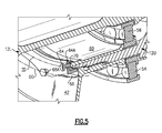
- the multiple of inner preload fasteners 64 engage a respective multiple of inner apertures 64A defined about an inner diameter ID and the multiple of outer preload fasteners 68 engage a respective multiple of outer apertures 68A defined about an outer diameter OD (also illustrated in Figure 5 ).
- the multiple of outer apertures 68A are circumferentially staggered relative the multiple of respective outer apertures 68A. Circumferentially staggered as defined herein locates each of the multiple of inner apertures 64A on a respective radial line which extends from the axis A such that each of the multiple of the outer apertures 68A are not located upon these radial lines.
- the multiple of inner preload fasteners 64 are torqued to provide a desired axial preload on the bearing retention inner sleeve 60 and the inner bearing 56.
- the multiple of outer preload fasteners 68 are torqued to provide a desired axial preload on the main gear 42 and the outer bearing 54.
- the multiple of inner preload fasteners 64 and the multiple of outer preload fasteners 68 abut the respective outer rotor shaft sacrificial washer 66 and main gear sacrificial washer 70 so as to minimize wear on the primary component.
- Sets of the multiple of inner preload fasteners 64 and the multiple of outer preload fasteners 68 may include lockwires L to assure retention. ( Figure 6 ).
- the locknut assembly 46 provides a light weight design, which facilitates manufacture of increased strength coaxial shaft arrangements through minimization or elimination of many screw thread radii and associated thread relief.
Description
- The present invention is directed to a locknut assembly, to a coaxial shaft system, to a method of generating an axial preload, and to an aircraft comprising such coaxial shaft systems.
- Various coaxial shaft arrangements utilize a locknut assembly to position and retain a component on the shaft structure. One such coaxial shaft arrangement is that of a rotary-wing aircraft counter-rotating, coaxial rotor system. The rotor system mounts a final gear reduction stage output gear to an outer rotor shaft via a spline and locknut. The coaxial rotor system also mounts an outer bearing on the outer diameter of the outer coaxial rotor shaft and an inner bearing between the outer coaxial rotor shaft and an inner diameter of the inner coaxial rotor shaft. The inner bearing also requires separate retention with an inner locknut.
- Although effective, such an inner locknut and outer locknut arrangement may require a relatively thick shaft wall to support both external and internal threads for each locknut. This may form the potential for a multiple of stress risers.
- A locknut and a corresponding assembly according to the features of the preamble of independent claim 1 is known from e.g.
US4622730 . - A locknut assembly according to an exemplary aspect of the present invention includes a locknut defined about an axis, the locknut defines a multiple of inner apertures about an inner diameter and a multiple of outer apertures about an outer diameter, as claimed in independent claim 1.
- A coaxial shaft system according to an exemplary aspect of the present invention includes an outer rotor shaft which rotates about an axis of rotation; an inner rotor shaft mounted through the outer rotor shaft; an outer bearing mounted about an outer diameter of the outer rotor shaft; an inner bearing mounted between the outer rotor shaft and the inner rotor shaft; an outer sleeve mounted about the outer rotor shaft to axially abut the outer bearing; an inner sleeve mounted within the outer rotor shaft to axially abut the inner bearing; and a locknut threaded to the outer rotor shaft about the axis of rotation, the locknut defines a multiple of inner apertures which align with the inner sleeve and a multiple of outer apertures which align with the outer sleeve.
- Further aspects of the invention are set out in the following numbered paragraphs:
- 1. A locknut assembly comprising:
- a locknut defined about an axis, said locknut defines a multiple of inner apertures about an inner diameter and a multiple of outer apertures about an outer diameter.
- 2. The assembly as recited in paragraph 1, wherein said locknut defines a locknut thread about said axis.
- 3. The assembly as recited in paragraph 2, wherein said locknut thread defines a locknut thread diameter intermediate said inner diameter and said outer diameter.
- 4. The assembly as recited in paragraph 1, wherein said multiple of inner apertures are circumferentially staggered relative to said multiple of outer apertures.
- 5. The assembly as recited in paragraph 1, further comprising:
- a multiple of inner preload fasteners engageable with said multiple of inner apertures; and
- a multiple of outer preload fasteners engageable with said multiple of outer apertures.
- 6. A coaxial shaft system comprising:
- an outer rotor shaft which rotates about an axis of rotation;
- an inner rotor shaft which rotates about said axis of rotation, said inner rotor shaft mounted through said outer rotor shaft;
- an outer bearing mounted about an outer diameter of said outer rotor shaft;
- an inner bearing mounted between said outer rotor shaft and said inner rotor shaft;
- an outer sleeve mounted about said outer rotor shaft to axially abut said outer bearing;
- an inner sleeve mounted within said outer rotor shaft to axially abut said inner bearing; and
- a locknut threaded to said outer rotor shaft about said axis of rotation, said locknut defines a multiple of inner apertures in axial alignment with a portion of said inner sleeve and a multiple of outer apertures in axial alignment with a portion of said outer sleeve.
- 7. The system as recited in paragraph 6, wherein said multiple of inner apertures are defined about an inner diameter and said multiple of outer apertures are defined about an outer diameter, said locknut thread intermediate said inner diameter and said outer diameter.
- 8. The system as recited in paragraph 6, wherein said outer sleeve is defined by a gear.
- 9. The system as recited in paragraph 6, wherein said outer bearing axially abuts a step defined in said outer diameter of said outer rotor shaft, said inner bearing axially abuts a step defined in an inner diameter of said outer rotor shaft and a step defined in an outer diameter of said inner rotor shaft.
- 10. The system as recited in paragraph 6, further comprising a lower rotor hub mounted to said outer rotor shaft and an upper rotor hub mounted to said inner rotor shaft.
- 11. The system as recited in paragraph 6, wherein said outer sleeve is mounted to said outer rotor shaft though a spline.
- 12. The system as recited in paragraph 11, further comprising:
- a multiple of inner preload fasteners engageable with said multiple of inner apertures to generate an axial preload to said inner sleeve; and
- a multiple of outer preload fasteners engageable with said multiple of outer apertures to generate an axial preload to said outer sleeve.
- 13. The system as recited in
paragraph 12, further comprising a first sacrificial washer mounted to said inner sleeve to receive said multiple of inner preload fasteners, and a second sacrificial washer mounted to said outer sleeve to receive said multiple of outer preload fasteners - 14. A method of generating an axial preload upon a coaxial shaft system comprising:
- threading a locknut to an outer rotor shaft, the outer rotor shaft mounted about an inner rotor shaft which rotate about an axis of rotation;
- threading an inner multiple of preload fasteners through said locknut to generate an axial preload upon an inner sleeve mounted within said outer rotor shaft; and
- threading an outer multiple of preload fasteners through said locknut to generate an axial preload upon an outer sleeve mounted about said outer rotor shaft.
- 15. A method as recited in
paragraph 14, further comprising:- abutting said inner sleeve with an inner bearing between the inner rotor shaft and the outer rotor shaft; and
- abutting said outer sleeve with an outer bearing, the outer bearing operable to support the outer rotor shaft.
- 16. An apparatus comprising:
- an outer rotor shaft which rotates about an axis of rotation;
- an inner rotor shaft which rotates about said axis of rotation, said inner rotor shaft mounted through said outer rotor shaft;
- an outer bearing mounted about an outer diameter of said outer rotor shaft;
- an inner bearing mounted between said outer rotor shaft and said inner rotor shaft;
- an outer sleeve mounted about said outer rotor shaft to axially abut said outer bearing;
- an inner sleeve mounted within said outer rotor shaft to axially abut said inner bearing; and
- a locknut threaded to said outer rotor shaft about said axis of rotation, said locknut defines a multiple of inner apertures in axial alignment with a portion of said inner sleeve and a multiple of outer apertures in axial alignment with a portion of said outer sleeve.
- 17. The system as recited in
paragraph 16, wherein said apparatus comprises an aircraft. - 18. The system as recited in
paragraph 16, wherein said apparatus comprises an rotary-wing aircraft. - 19. The system as recited in
paragraph 16, wherein said apparatus comprises a helicopter. - The various features and advantages of this invention will become apparent to those skilled in the art from the following detailed description of the currently preferred embodiment. The drawings that accompany the detailed description can be briefly described as follows:
-
Figure 1A is a general schematic views of an exemplary rotary wing aircraft embodiment for use with the present invention; -
Figure 2A is an expanded perspective view of a counter-rotating coaxial rotor system; -
Figure 2b is an exploded view of the counter-rotating coaxial rotor system offigure 2A ; -
Figure 3 is a side sectional view of a locknut assembly; -
Figure 4 is a perspective view of the locknut assembly; -
Figure 5 is an expanded perspective sectional view of the locknut assembly; and -
Figure 6 is an expanded view of a locknut assembly preload fasteners lockwired together. -
Figure 1 illustrates an exemplary vertical takeoff and landing (VTOL) rotary-wing aircraft 10 having a dual, counter-rotating,coaxial rotor system 12 which rotates about an axis of rotation A. Theaircraft 10 includes anairframe 14 which supports the dual, counter rotating,coaxial rotor system 12 as well as an optionaltranslational thrust system 30 which provides translational thrust generally parallel to an aircraft longitudinal axis L. Although a particular aircraft configuration is illustrated in the disclosed embodiment, other counter-rotating, coaxial rotor systems as well as any coaxial shaft arrangement will also benefit from the present invention. - The dual, counter-rotating,
coaxial rotor system 12 includes anupper rotor system 16 and alower rotor system 18. Eachrotor system rotor blades 20 mounted to arotor hub main rotor blades 20 project substantially radially outward from thehub assemblies blades 20 may be used with therotor system 12. - A
main gearbox 26 powered by one or more engines (illustrated schematically at E) drives therotor system 12. Thetranslational thrust system 30 may also be driven through themain gearbox 26. - The
translational thrust system 30 may be mounted to the rear of theairframe 14 with a rotational axis T oriented substantially horizontal and parallel to the aircraft longitudinal axis L to provide thrust for high-speed flight. Thetranslational thrust system 30 includes apusher propeller 32 mounted within anaerodynamic cowling 34. Although a tail mountedtranslational thrust system 30 is disclosed in the illustrated non-limiting embodiment, it should be understood that other translational thrust systems including tractor and pod mounted systems may alternatively or additionally be utilized. - Referring to
Figure 2A , the dual, counter-rotating,coaxial rotor system 12 includes aninner rotor shaft 12U which mounts therotor hub 22 and anouter rotor shaft 12L which mounts therotor hub 24. Theinner rotor shaft 12U and theouter rotor shaft 12L are driven in a counter-rotational arrangement by themain gearbox 26 through, in one non-limiting embodiment, aspline arrangement 40 on theinner rotor shaft 12U and amain gear 42 mounted to theouter rotor shaft 12L. - The
main gear 42 and a bearing system 44 are retained on theouter rotor shaft 12L through alocknut assembly 46 such that theouter rotor shaft 12L and themain gear 42 mounted thereto may counter-rotate relative theinner rotor shaft 12U upon the bearing system 44 (Figure 2B ). It should be understood that although amain rotor system 12 is illustrated in the non-limiting embodiment, other coaxial shaft systems may also utilize thelocknut assembly 46. It should also be understood that although a single bearing system 44 is illustrated in the non-limiting embodiment, any number of bearing systems 44 may be utilized with this or other such coaxial shaft systems. - Referring to
Figure 3 , themain gear 42 is rotationally locked to theouter rotor shaft 12L though amain gear spline 50 which engages with an outerrotor shaft spline 52. Themain gear 42 may include a main gearouter sleeve section 42S which axially abuts the bearing system 44. It should be understood that other constructions including separate sleeves and such like may alternatively or additionally be provided. - The bearing system 44 generally includes an
outer bearing 54 and aninner bearing 56. Theouter bearing 54 is positioned between theouter rotor shaft 12L and {a?} rotationally fixed component such as ahousing 26H of the main gearbox 26 (also illustrated inFigure 4 ). Theouter bearing 54 abuts an outer outer-shaft step 48a in theouter rotor shaft 12L. An outersacrificial sleeve 58a may be utilized to mount theouter bearing 54 toouter rotor shaft 12L. Theinner bearing 56 is positioned between theouter rotor shaft 12L and theinner rotor shaft 12U to provide relative rotation therebetween. Theinner bearing 56 abuts an inner outer-shaft step 48b and an outer inner-shaft step 48c. Theinner bearing 56 may be mounted to theouter rotor shaft 12L and theinner rotor shaft 12U though respectivesacrificial sleeves sacrificial sleeves respective steps - The main gear
outer sleeve section 42S, defined about an outer diameter of theouter rotor shaft 12L, axially abuts theouter bearing 54 opposite thestep 48a. A bearing retentioninner sleeve 60 mounted within an inner diameter of theouter rotor shaft 12L axially abuts theinner bearing 56 opposite thesteps main gear 42 and the bearing retentioninner sleeve 60 are axially locked through thelocknut assembly 46. - The
locknut assembly 46 generally includes alocknut 62, a multiple ofinner preload fasteners 64, an outersacrificial washer 66, a multiple ofouter preload fasteners 68 and an innersacrificial washer 70. Thelocknut 62 includes alocknut thread 62T which threadably engages acorresponding thread 12T on theouter rotor shaft 12L. That is, thelocknut 62 is threaded onto theouter rotor shaft 12L to axially lock the bearing system 44, themain gear 42 and the bearing retentioninner sleeve 60 onto theouter rotor shaft 12L. thereto. - The multiple of
inner preload fasteners 64 engage a respective multiple of inner apertures 64A defined about an inner diameter ID and the multiple ofouter preload fasteners 68 engage a respective multiple ofouter apertures 68A defined about an outer diameter OD (also illustrated inFigure 5 ). The multiple ofouter apertures 68A are circumferentially staggered relative the multiple of respectiveouter apertures 68A. Circumferentially staggered as defined herein locates each of the multiple of inner apertures 64A on a respective radial line which extends from the axis A such that each of the multiple of theouter apertures 68A are not located upon these radial lines. - The multiple of
inner preload fasteners 64 are torqued to provide a desired axial preload on the bearing retentioninner sleeve 60 and theinner bearing 56. The multiple ofouter preload fasteners 68 are torqued to provide a desired axial preload on themain gear 42 and theouter bearing 54. The multiple ofinner preload fasteners 64 and the multiple ofouter preload fasteners 68 abut the respective outer rotor shaftsacrificial washer 66 and main gearsacrificial washer 70 so as to minimize wear on the primary component. Sets of the multiple ofinner preload fasteners 64 and the multiple ofouter preload fasteners 68 may include lockwires L to assure retention. (Figure 6 ). - The
locknut assembly 46 provides a light weight design, which facilitates manufacture of increased strength coaxial shaft arrangements through minimization or elimination of many screw thread radii and associated thread relief. - It should be understood that relative positional terms such as "forward," "aft," "upper," "lower," "above," "below," and the like are with reference to an illustrated attitude of the structure and should not be considered otherwise limiting.
- Although particular step sequences are shown, described, and claimed, it should be understood that steps may be performed in any order, separated or combined unless otherwise indicated and will still benefit from the present invention.
Claims (13)
- A locknut assembly (46) comprising:a locknut (62) defined about an axis (A), said locknut (62) defines a multiple of inner apertures (64A) and a multiple of outer apertures (68A), whereinall apertures (64A, 68A) are defined generally parallel to said axis (A) and through a common plane, which is oriented basically perpendicular to said axis (A),said inner apertures (64A) are arranged on an inner circle (ID) having a first diameter with respect to the axis (A) and the multiple of outer apertures (68A) are arranged on an outer circle (OD) having a second diameter with respect to the axis (A), the second diameter being larger than the first diameter andsaid multiple of inner apertures (64A) are at least partially threaded and said multiple of outer apertures (68A) are at least partially threaded,characterized in thatsaid locknut (62) defines a locknut thread (62T) about said axis (A), said locknut thread (62T) defines a locknut thread diameter intermediate said first diameter and said second diameter.
- The assembly (46) as recited in claim 1, wherein said multiple of inner apertures (64A) are circumferentially staggered relative to said multiple of outer apertures (68A) through a generally planar surface.
- The assembly (46) as recited in any of claims 1 or 2, further comprising:a multiple of inner preload fasteners (64) threadably engageable with said multiple of inner apertures (64A); anda multiple of outer preload fasteners (68) threadably engageable with said multiple of outer apertures (68A).
- A coaxial shaft system (12) comprising: a locknut assembly (46) as recited in any of claims 1 to 3;
an outer rotor shaft (12L) which rotates about said axis of rotation (A);
an inner rotor shaft (12U) which rotates about said axis of rotation (A), said inner rotor shaft (12U) mounted through said outer rotor shaft (12L);
an outer bearing (54) mounted about an outer diameter of said outer rotor shaft (12L);
an inner bearing (56) mounted between said outer rotor shaft (12L) and said inner rotor shaft (12U);
an outer sleeve (42S) mounted about said outer rotor shaft (12L) to axially abut said outer bearing (54); and
an inner sleeve (60) mounted within said outer rotor shaft (12L) to axially abut said inner bearing (56);
said locknut (62) threaded to said outer rotor shaft (12L) about said axis of rotation (A). - The system (12) as recited in claim 4, wherein said outer sleeve (42S) is defined by a gear (42).
- The system (12) as recited in claim 4 or 5, wherein said outer bearing (54) axially abuts a step (48a) defined in said outer diameter of said outer rotor shaft (12L), said inner bearing (56) axially abuts a step (48b) defined in an inner diameter of said outer rotor shaft (12L) and a step (48c) defined in an outer diameter of said inner rotor shaft (12U).
- The system (12) as recited in any of claims 4 to 6, further comprising a lower rotor hub mounted (24) to said outer rotor shaft (12L) and an upper rotor hub (22) mounted to said inner rotor shaft (12U).
- The system (12) as recited in any of claims 4 to 7, wherein said outer sleeve (42S) is mounted to said outer rotor shaft (12L) though a spline (50).
- The system (12) as recited in claim 8, wherein
said multiple of inner preload fasteners (64) is threadably engageable with said multiple of inner apertures (64A) to generate an axial preload to said inner sleeve (60); and
said multiple of outer preload fasteners (68) is threadably engageable with said multiple of outer apertures (68A) to generate an axial preload to said outer sleeve (42S). - The system (12) as recited in claim 9, further comprising a first sacrificial washer (70) mounted to said inner sleeve (60) to receive said multiple of inner preload fasteners (64), and a second sacrificial washer (66) mounted to said outer sleeve (42S) to receive said multiple of outer preload fasteners (68).
- An aircraft, in particular a rotary-wing aircraft or a helicopter, comprising a coaxial shaft system (12) as recited in any of claims 4 to 10.
- A method of generating an axial preload upon a coaxial shaft system (12) comprising:threading a locknut (62) which defines a locknut thread (62T) about said axis (A), said locknut thread (62T) defines a locknut thread diameter intermediate said first diameter and said second diameter and said locknut (62) comprises a multiple of inner apertures (64A) and a multiple of outer apertures (68A), wherein all apertures (64A, 68A) are defined generally parallel to said axis (A) and through a common plane, which is oriented basically perpendicular to said axis (A), said inner apertures (64A) are arranged on an inner circle (ID) having a first diameter with respect to the axis (A) and the multiple of outer apertures (68A) are arranged in an outer circle (OD) having a second diameter with respect to the axis (A), the second diameter being larger than the first diameter and said multiple of inner apertures (64A) are at least partially threaded and said multiple of outer apertures (68A) are at least partially threaded to an outer rotor shaft (12L), the outer rotor shaft (12L) mounted about an inner rotor shaft (12U), which rotate about an axis of rotation;threading an inner multiple of preload fasteners (64) through said inner apertures (64A) to generate an axial preload upon an inner sleeve (60) mounted within said outer rotor shaft (12L); andthreading an outer multiple of preload fasteners (68) through said outer apertures (68A) to generate an axial preload upon an outer sleeve (42S) mounted about said outer rotor shaft (12L).
- The method as recited in claim 12, further comprising:abutting said inner sleeve (60) with an inner bearing (56) between the inner rotor shaft (12U) and the outer rotor shaft (12L); andabutting said outer sleeve (42S) with an outer bearing (54), the outer bearing (54) operable to support the outer rotor shaft (12L).
Applications Claiming Priority (1)
| Application Number | Priority Date | Filing Date | Title |
|---|---|---|---|
| PCT/US2007/088505 WO2009082396A1 (en) | 2007-12-21 | 2007-12-21 | Locknut assembly for a coaxial shaft |
Publications (3)
| Publication Number | Publication Date |
|---|---|
| EP2234878A1 EP2234878A1 (en) | 2010-10-06 |
| EP2234878A4 EP2234878A4 (en) | 2013-02-20 |
| EP2234878B1 true EP2234878B1 (en) | 2015-05-27 |
Family
ID=40801493
Family Applications (1)
| Application Number | Title | Priority Date | Filing Date |
|---|---|---|---|
| EP07869722.4A Not-in-force EP2234878B1 (en) | 2007-12-21 | 2007-12-21 | Locknut assembly for a coaxial shaft |
Country Status (3)
| Country | Link |
|---|---|
| US (1) | US8303208B2 (en) |
| EP (1) | EP2234878B1 (en) |
| WO (1) | WO2009082396A1 (en) |
Families Citing this family (10)
| Publication number | Priority date | Publication date | Assignee | Title |
|---|---|---|---|---|
| US7571541B2 (en) * | 2005-01-10 | 2009-08-11 | Silverbrook Research Pty Ltd | Method of producing an inkjet printhead for an inkjet printer with a print engine controller |
| CN101618763A (en) * | 2008-07-02 | 2010-01-06 | 孙为红 | Miniature high-speed vertical-lifting self rotor aircraft |
| GB201114188D0 (en) * | 2011-08-18 | 2011-10-05 | Rolls Royce Plc | A clamping assembly |
| US9254915B2 (en) * | 2013-08-26 | 2016-02-09 | Bell Helicopter Textron Inc. | Rotor system with torque-splitter assembly |
| US20150122941A1 (en) * | 2013-11-06 | 2015-05-07 | Sikorsky Aircraft Corporation | Counter-rotating rotor system with fairing |
| WO2015102634A1 (en) * | 2014-01-02 | 2015-07-09 | Sikorsky Aircraft Corporation | Rotor apparatus |
| US11060605B2 (en) * | 2018-07-09 | 2021-07-13 | Textron Innovations Inc. | Spherical mounted cylindrical roller bearing system |
| DE102020200888A1 (en) * | 2020-01-27 | 2021-05-20 | Zf Friedrichshafen Ag | Fixation of a spline |
| CA3186638A1 (en) * | 2020-06-10 | 2021-12-16 | Mehmet Bora KUZUCAN | Coupling arrangement |
| CN112249343B (en) * | 2020-10-29 | 2022-02-22 | 中国航发湖南动力机械研究所 | Tail transmission shaft and helicopter |
Citations (2)
| Publication number | Priority date | Publication date | Assignee | Title |
|---|---|---|---|---|
| US2899222A (en) * | 1959-08-11 | Shaft end roll mounting | ||
| US4622730A (en) * | 1984-03-30 | 1986-11-18 | Rolf Steinbock | Apparatus to mechanically stress a bolt-type fastener |
Family Cites Families (31)
| Publication number | Priority date | Publication date | Assignee | Title |
|---|---|---|---|---|
| US1420737A (en) * | 1921-12-01 | 1922-06-27 | Skf Svenska Kullagerfab Ab | Nut lock |
| US4175913A (en) * | 1978-01-13 | 1979-11-27 | The United States Of America As Represented By The Secretary Of The Army | Helicopter rotor head mounting assembly |
| FR2416839A1 (en) | 1978-02-10 | 1979-09-07 | Aerospatiale | RESONATOR DEVICE TO MITIGATE THE VIBRATIONS OF A GIRAVION ROTOR |
| US4505628A (en) | 1981-03-09 | 1985-03-19 | Meibuhr George C | Bearing locknut |
| US4583704A (en) * | 1983-12-27 | 1986-04-22 | United Technologies Corporation | Pneumatic system structure for circulation control aircraft |
| USRE33490E (en) * | 1984-03-30 | 1990-12-18 | Apparatus to mechanically stress a bolt-type fastener | |
| US4575102A (en) * | 1984-11-20 | 1986-03-11 | Ferrofluidics Corporation | Coaxial, multiple-shaft ferrofluid seal apparatus |
| IT207278Z2 (en) * | 1985-10-01 | 1988-01-04 | Merlo Ind Metalmecc | FORK LIFT TRUCK |
| US5116178A (en) * | 1989-03-16 | 1992-05-26 | General Electric Company | Safety cable for fasteners |
| US5224360A (en) * | 1989-11-12 | 1993-07-06 | Precision Fukuhara Works, Ltd. | Circular knitting machine having removable cylinder |
| FR2661886B1 (en) | 1990-05-14 | 1992-08-28 | Aerospatiale | DEVICE WITH CYCLIC PLATES MOUNTED ON JOINTS DECOUPLED INTO TANGING AND ROLLING, FOR CONTROLLING THE PITCH OF THE BLADES OF A GIRAVION ROTOR. |
| US5069587A (en) * | 1990-06-13 | 1991-12-03 | Dresser Industries, Inc. | Securing nut apparatus |
| US5266008A (en) * | 1991-05-07 | 1993-11-30 | Mcdonnell Douglas Helicopter Company | Fail-safe nut retainer for a helicopter |
| US5197345A (en) * | 1991-11-15 | 1993-03-30 | Reliance Electric Industrial Company | Taper bushed screw conveyor drive and method with demount feature |
| US5203441A (en) * | 1992-06-01 | 1993-04-20 | Eaton Corporation | Adaptor for use in a flywheel and transmission assembly |
| US5273497A (en) | 1992-10-16 | 1993-12-28 | Wallace Associated Research | Mechanical transmission with infinite-ratio gearing |
| DE19547981A1 (en) * | 1994-12-28 | 1996-07-04 | Dana Corp | Wheel end assembly for car drive and steering axle |
| US5791592A (en) | 1995-01-18 | 1998-08-11 | Nolan; Herbert M. | Helicopter with coaxial counter-rotating dual rotors and no tail rotor |
| US5609456A (en) * | 1995-02-21 | 1997-03-11 | The Timken Corporation | Locking nut |
| US5662445A (en) * | 1996-03-06 | 1997-09-02 | The Timken Company | Locking nut |
| ITPD980007A1 (en) * | 1998-01-15 | 1999-07-15 | Giorgio Casarotto | COUPLING SYSTEM BETWEEN A SHAFT AND A BLIND HOLLOW PART, PARTICULARLY FOR PLANETARY REDUCERS |
| US6293492B1 (en) | 1998-09-02 | 2001-09-25 | Engineering System Co., Ltd. | Coaxial twin-rotor type helicopter |
| US6019578A (en) | 1998-12-18 | 2000-02-01 | Sikorsky Aircraft Corporation | Variable diameter rotor blade actuation system |
| US6030177A (en) | 1998-12-18 | 2000-02-29 | Sikorsky Aircraft Corporation | Drive system for a variable diameter tilt rotor |
| IT1309989B1 (en) | 1999-06-29 | 2002-02-05 | Gd Spa | ROLLER HANDLING DEVICE IN AUTOMATIC MACHINES. |
| US7615893B2 (en) * | 2000-05-11 | 2009-11-10 | Cameron International Corporation | Electric control and supply system |
| DE20022827U1 (en) * | 2000-10-16 | 2002-06-13 | Sew Eurodrive Gmbh & Co | jig |
| FR2837784B1 (en) * | 2002-03-28 | 2004-05-28 | Eurocopter France | CELLULAR DRIVE ROTOR ROTOR WITH TORQUE SHARING DIFFERENTIAL |
| US7030528B2 (en) | 2003-02-06 | 2006-04-18 | General Motors Corporation | Dual concentric AC motor |
| US6893160B2 (en) | 2003-09-10 | 2005-05-17 | Rexnord Industries, Inc. | Bearing assembly |
| WO2010096644A1 (en) * | 2009-02-19 | 2010-08-26 | Stolle Machinery Company, Llc | Ram bearing assembly, seal assembly therefor and associated method |
-
2007
- 2007-12-21 WO PCT/US2007/088505 patent/WO2009082396A1/en active Application Filing
- 2007-12-21 EP EP07869722.4A patent/EP2234878B1/en not_active Not-in-force
- 2007-12-21 US US12/809,633 patent/US8303208B2/en not_active Expired - Fee Related
Patent Citations (2)
| Publication number | Priority date | Publication date | Assignee | Title |
|---|---|---|---|---|
| US2899222A (en) * | 1959-08-11 | Shaft end roll mounting | ||
| US4622730A (en) * | 1984-03-30 | 1986-11-18 | Rolf Steinbock | Apparatus to mechanically stress a bolt-type fastener |
Non-Patent Citations (1)
| Title |
|---|
| "Taper Line, INC.", Retrieved from the Internet <URL:http://www.taperline.com/images/heavy_duty_inch_spindle_lock_nuts> * |
Also Published As
| Publication number | Publication date |
|---|---|
| WO2009082396A1 (en) | 2009-07-02 |
| EP2234878A1 (en) | 2010-10-06 |
| EP2234878A4 (en) | 2013-02-20 |
| US8303208B2 (en) | 2012-11-06 |
| US20100270421A1 (en) | 2010-10-28 |
Similar Documents
| Publication | Publication Date | Title |
|---|---|---|
| EP2234878B1 (en) | Locknut assembly for a coaxial shaft | |
| US7607607B2 (en) | De-rotation system suitable for use with a shaft fairing system | |
| US8534596B2 (en) | Planetary de-rotation system for a shaft fairing system | |
| EP1885601B1 (en) | Split torque gearbox for rotary wing aircraft with translational thrust system | |
| US10183745B2 (en) | Tiltrotor with inboard engines | |
| US20150125299A1 (en) | Counter-rotating rotor system with stationary standpipe | |
| US20160207619A1 (en) | Light weight propulsor gearbox | |
| US10112708B2 (en) | Weight efficient servo attachment scheme for rigid coaxial rotor control system | |
| EP2976259B1 (en) | Flexbeam to rotor blade interface | |
| EP2873613B1 (en) | Counter-rotating rotor system with static mast | |
| EP3038909A1 (en) | Rotor hub for rotary wing aircraft | |
| US10960972B2 (en) | Rotorcraft masts having a nonintegral raceway | |
| US10647410B2 (en) | Spinner shaft attachment | |
| US11161606B2 (en) | Flexured standpipes for aircraft propulsion assemblies | |
| US11149741B2 (en) | Variable pitch fan for a gas turbine engine | |
| US10793264B2 (en) | Flex beam clamp for rotor assembly | |
| US20230136833A1 (en) | Rotor blade non-counterbored retention assembly via a sliding clamped bushing | |
| US11493121B2 (en) | Gear systems having bearing flexure mounted thrust bearings | |
| US10654566B2 (en) | Integrated main rotor hub and shaft | |
| US11655020B2 (en) | Non rotationally constrained friction damper for drive shaft |
Legal Events
| Date | Code | Title | Description |
|---|---|---|---|
| PUAI | Public reference made under article 153(3) epc to a published international application that has entered the european phase |
Free format text: ORIGINAL CODE: 0009012 |
|
| 17P | Request for examination filed |
Effective date: 20100716 |
|
| AK | Designated contracting states |
Kind code of ref document: A1 Designated state(s): AT BE BG CH CY CZ DE DK EE ES FI FR GB GR HU IE IS IT LI LT LU LV MC MT NL PL PT RO SE SI SK TR |
|
| AX | Request for extension of the european patent |
Extension state: AL BA HR MK RS |
|
| DAX | Request for extension of the european patent (deleted) | ||
| A4 | Supplementary search report drawn up and despatched |
Effective date: 20130123 |
|
| RIC1 | Information provided on ipc code assigned before grant |
Ipc: B64C 11/04 20060101AFI20130117BHEP Ipc: F16D 1/108 20060101ALN20130117BHEP Ipc: B64C 27/10 20060101ALN20130117BHEP Ipc: B64C 27/14 20060101ALN20130117BHEP |
|
| RIC1 | Information provided on ipc code assigned before grant |
Ipc: B64C 27/14 20060101ALN20130605BHEP Ipc: B64C 27/10 20060101ALN20130605BHEP Ipc: B64C 11/04 20060101AFI20130605BHEP Ipc: F16D 1/108 20060101ALN20130605BHEP |
|
| 17Q | First examination report despatched |
Effective date: 20130719 |
|
| RIC1 | Information provided on ipc code assigned before grant |
Ipc: B64C 11/04 20060101AFI20131127BHEP Ipc: B64C 27/14 20060101ALN20131127BHEP Ipc: B64C 27/10 20060101ALN20131127BHEP Ipc: F16D 1/108 20060101ALN20131127BHEP Ipc: F16D 1/10 20060101ALN20131127BHEP |
|
| RIC1 | Information provided on ipc code assigned before grant |
Ipc: B64C 11/04 20060101AFI20131202BHEP Ipc: F16D 1/108 20060101ALN20131202BHEP Ipc: B64C 27/14 20060101ALN20131202BHEP Ipc: F16D 1/10 20060101ALN20131202BHEP Ipc: B64C 27/10 20060101ALN20131202BHEP |
|
| RIC1 | Information provided on ipc code assigned before grant |
Ipc: B64C 11/04 20060101AFI20140702BHEP Ipc: F16D 1/108 20060101ALN20140702BHEP Ipc: B64C 27/14 20060101ALN20140702BHEP Ipc: B64C 27/10 20060101ALN20140702BHEP Ipc: F16D 1/10 20060101ALN20140702BHEP |
|
| GRAP | Despatch of communication of intention to grant a patent |
Free format text: ORIGINAL CODE: EPIDOSNIGR1 |
|
| RIC1 | Information provided on ipc code assigned before grant |
Ipc: F16D 1/10 20060101ALN20140725BHEP Ipc: B64C 11/04 20060101AFI20140725BHEP Ipc: B64C 27/10 20060101ALN20140725BHEP Ipc: B64C 27/14 20060101ALN20140725BHEP Ipc: F16D 1/108 20060101ALN20140725BHEP |
|
| INTG | Intention to grant announced |
Effective date: 20140811 |
|
| RIN1 | Information on inventor provided before grant (corrected) |
Inventor name: TULLY, THOMAS, L. |
|
| RIC1 | Information provided on ipc code assigned before grant |
Ipc: F16D 1/108 20060101ALN20141203BHEP Ipc: F16D 1/10 20060101ALN20141203BHEP Ipc: B64C 27/10 20060101ALN20141203BHEP Ipc: B64C 27/14 20060101ALN20141203BHEP Ipc: B64C 11/04 20060101AFI20141203BHEP |
|
| GRAP | Despatch of communication of intention to grant a patent |
Free format text: ORIGINAL CODE: EPIDOSNIGR1 |
|
| INTG | Intention to grant announced |
Effective date: 20150108 |
|
| RIC1 | Information provided on ipc code assigned before grant |
Ipc: B64C 27/10 20060101ALN20141217BHEP Ipc: B64C 27/14 20060101ALN20141217BHEP Ipc: F16D 1/10 20060101ALN20141217BHEP Ipc: B64C 11/04 20060101AFI20141217BHEP Ipc: F16D 1/108 20060101ALN20141217BHEP |
|
| GRAS | Grant fee paid |
Free format text: ORIGINAL CODE: EPIDOSNIGR3 |
|
| GRAA | (expected) grant |
Free format text: ORIGINAL CODE: 0009210 |
|
| AK | Designated contracting states |
Kind code of ref document: B1 Designated state(s): AT BE BG CH CY CZ DE DK EE ES FI FR GB GR HU IE IS IT LI LT LU LV MC MT NL PL PT RO SE SI SK TR |
|
| REG | Reference to a national code |
Ref country code: GB Ref legal event code: FG4D |
|
| REG | Reference to a national code |
Ref country code: CH Ref legal event code: EP |
|
| REG | Reference to a national code |
Ref country code: AT Ref legal event code: REF Ref document number: 728689 Country of ref document: AT Kind code of ref document: T Effective date: 20150615 |
|
| REG | Reference to a national code |
Ref country code: IE Ref legal event code: FG4D |
|
| REG | Reference to a national code |
Ref country code: DE Ref legal event code: R096 Ref document number: 602007041607 Country of ref document: DE |
|
| REG | Reference to a national code |
Ref country code: AT Ref legal event code: MK05 Ref document number: 728689 Country of ref document: AT Kind code of ref document: T Effective date: 20150527 |
|
| REG | Reference to a national code |
Ref country code: LT Ref legal event code: MG4D |
|
| PG25 | Lapsed in a contracting state [announced via postgrant information from national office to epo] |
Ref country code: PT Free format text: LAPSE BECAUSE OF FAILURE TO SUBMIT A TRANSLATION OF THE DESCRIPTION OR TO PAY THE FEE WITHIN THE PRESCRIBED TIME-LIMIT Effective date: 20150928 Ref country code: LT Free format text: LAPSE BECAUSE OF FAILURE TO SUBMIT A TRANSLATION OF THE DESCRIPTION OR TO PAY THE FEE WITHIN THE PRESCRIBED TIME-LIMIT Effective date: 20150527 Ref country code: FI Free format text: LAPSE BECAUSE OF FAILURE TO SUBMIT A TRANSLATION OF THE DESCRIPTION OR TO PAY THE FEE WITHIN THE PRESCRIBED TIME-LIMIT Effective date: 20150527 Ref country code: ES Free format text: LAPSE BECAUSE OF FAILURE TO SUBMIT A TRANSLATION OF THE DESCRIPTION OR TO PAY THE FEE WITHIN THE PRESCRIBED TIME-LIMIT Effective date: 20150527 |
|
| REG | Reference to a national code |
Ref country code: NL Ref legal event code: MP Effective date: 20150527 |
|
| PG25 | Lapsed in a contracting state [announced via postgrant information from national office to epo] |
Ref country code: LV Free format text: LAPSE BECAUSE OF FAILURE TO SUBMIT A TRANSLATION OF THE DESCRIPTION OR TO PAY THE FEE WITHIN THE PRESCRIBED TIME-LIMIT Effective date: 20150527 Ref country code: AT Free format text: LAPSE BECAUSE OF FAILURE TO SUBMIT A TRANSLATION OF THE DESCRIPTION OR TO PAY THE FEE WITHIN THE PRESCRIBED TIME-LIMIT Effective date: 20150527 Ref country code: IS Free format text: LAPSE BECAUSE OF FAILURE TO SUBMIT A TRANSLATION OF THE DESCRIPTION OR TO PAY THE FEE WITHIN THE PRESCRIBED TIME-LIMIT Effective date: 20150927 Ref country code: GR Free format text: LAPSE BECAUSE OF FAILURE TO SUBMIT A TRANSLATION OF THE DESCRIPTION OR TO PAY THE FEE WITHIN THE PRESCRIBED TIME-LIMIT Effective date: 20150828 Ref country code: BG Free format text: LAPSE BECAUSE OF FAILURE TO SUBMIT A TRANSLATION OF THE DESCRIPTION OR TO PAY THE FEE WITHIN THE PRESCRIBED TIME-LIMIT Effective date: 20150827 |
|
| REG | Reference to a national code |
Ref country code: FR Ref legal event code: PLFP Year of fee payment: 9 |
|
| PG25 | Lapsed in a contracting state [announced via postgrant information from national office to epo] |
Ref country code: EE Free format text: LAPSE BECAUSE OF FAILURE TO SUBMIT A TRANSLATION OF THE DESCRIPTION OR TO PAY THE FEE WITHIN THE PRESCRIBED TIME-LIMIT Effective date: 20150527 Ref country code: DK Free format text: LAPSE BECAUSE OF FAILURE TO SUBMIT A TRANSLATION OF THE DESCRIPTION OR TO PAY THE FEE WITHIN THE PRESCRIBED TIME-LIMIT Effective date: 20150527 |
|
| PG25 | Lapsed in a contracting state [announced via postgrant information from national office to epo] |
Ref country code: RO Free format text: LAPSE BECAUSE OF NON-PAYMENT OF DUE FEES Effective date: 20150527 Ref country code: SK Free format text: LAPSE BECAUSE OF FAILURE TO SUBMIT A TRANSLATION OF THE DESCRIPTION OR TO PAY THE FEE WITHIN THE PRESCRIBED TIME-LIMIT Effective date: 20150527 Ref country code: CZ Free format text: LAPSE BECAUSE OF FAILURE TO SUBMIT A TRANSLATION OF THE DESCRIPTION OR TO PAY THE FEE WITHIN THE PRESCRIBED TIME-LIMIT Effective date: 20150527 Ref country code: PL Free format text: LAPSE BECAUSE OF FAILURE TO SUBMIT A TRANSLATION OF THE DESCRIPTION OR TO PAY THE FEE WITHIN THE PRESCRIBED TIME-LIMIT Effective date: 20150527 |
|
| REG | Reference to a national code |
Ref country code: DE Ref legal event code: R097 Ref document number: 602007041607 Country of ref document: DE |
|
| PLBE | No opposition filed within time limit |
Free format text: ORIGINAL CODE: 0009261 |
|
| STAA | Information on the status of an ep patent application or granted ep patent |
Free format text: STATUS: NO OPPOSITION FILED WITHIN TIME LIMIT |
|
| 26N | No opposition filed |
Effective date: 20160301 |
|
| PG25 | Lapsed in a contracting state [announced via postgrant information from national office to epo] |
Ref country code: BE Free format text: LAPSE BECAUSE OF NON-PAYMENT OF DUE FEES Effective date: 20151231 Ref country code: SI Free format text: LAPSE BECAUSE OF FAILURE TO SUBMIT A TRANSLATION OF THE DESCRIPTION OR TO PAY THE FEE WITHIN THE PRESCRIBED TIME-LIMIT Effective date: 20150527 |
|
| PG25 | Lapsed in a contracting state [announced via postgrant information from national office to epo] |
Ref country code: MC Free format text: LAPSE BECAUSE OF FAILURE TO SUBMIT A TRANSLATION OF THE DESCRIPTION OR TO PAY THE FEE WITHIN THE PRESCRIBED TIME-LIMIT Effective date: 20150527 Ref country code: LU Free format text: LAPSE BECAUSE OF FAILURE TO SUBMIT A TRANSLATION OF THE DESCRIPTION OR TO PAY THE FEE WITHIN THE PRESCRIBED TIME-LIMIT Effective date: 20151221 |
|
| REG | Reference to a national code |
Ref country code: CH Ref legal event code: PL |
|
| PG25 | Lapsed in a contracting state [announced via postgrant information from national office to epo] |
Ref country code: BE Free format text: LAPSE BECAUSE OF FAILURE TO SUBMIT A TRANSLATION OF THE DESCRIPTION OR TO PAY THE FEE WITHIN THE PRESCRIBED TIME-LIMIT Effective date: 20150527 |
|
| REG | Reference to a national code |
Ref country code: IE Ref legal event code: MM4A |
|
| PG25 | Lapsed in a contracting state [announced via postgrant information from national office to epo] |
Ref country code: CH Free format text: LAPSE BECAUSE OF NON-PAYMENT OF DUE FEES Effective date: 20151231 Ref country code: IE Free format text: LAPSE BECAUSE OF NON-PAYMENT OF DUE FEES Effective date: 20151221 Ref country code: LI Free format text: LAPSE BECAUSE OF NON-PAYMENT OF DUE FEES Effective date: 20151231 |
|
| REG | Reference to a national code |
Ref country code: FR Ref legal event code: PLFP Year of fee payment: 10 |
|
| PG25 | Lapsed in a contracting state [announced via postgrant information from national office to epo] |
Ref country code: HU Free format text: LAPSE BECAUSE OF FAILURE TO SUBMIT A TRANSLATION OF THE DESCRIPTION OR TO PAY THE FEE WITHIN THE PRESCRIBED TIME-LIMIT; INVALID AB INITIO Effective date: 20071221 |
|
| PG25 | Lapsed in a contracting state [announced via postgrant information from national office to epo] |
Ref country code: CY Free format text: LAPSE BECAUSE OF FAILURE TO SUBMIT A TRANSLATION OF THE DESCRIPTION OR TO PAY THE FEE WITHIN THE PRESCRIBED TIME-LIMIT Effective date: 20150527 Ref country code: SE Free format text: LAPSE BECAUSE OF FAILURE TO SUBMIT A TRANSLATION OF THE DESCRIPTION OR TO PAY THE FEE WITHIN THE PRESCRIBED TIME-LIMIT Effective date: 20150527 Ref country code: NL Free format text: LAPSE BECAUSE OF FAILURE TO SUBMIT A TRANSLATION OF THE DESCRIPTION OR TO PAY THE FEE WITHIN THE PRESCRIBED TIME-LIMIT Effective date: 20150527 |
|
| REG | Reference to a national code |
Ref country code: DE Ref legal event code: R082 Ref document number: 602007041607 Country of ref document: DE Representative=s name: SCHMITT-NILSON SCHRAUD WAIBEL WOHLFROM PATENTA, DE |
|
| PG25 | Lapsed in a contracting state [announced via postgrant information from national office to epo] |
Ref country code: TR Free format text: LAPSE BECAUSE OF FAILURE TO SUBMIT A TRANSLATION OF THE DESCRIPTION OR TO PAY THE FEE WITHIN THE PRESCRIBED TIME-LIMIT Effective date: 20150527 Ref country code: MT Free format text: LAPSE BECAUSE OF FAILURE TO SUBMIT A TRANSLATION OF THE DESCRIPTION OR TO PAY THE FEE WITHIN THE PRESCRIBED TIME-LIMIT Effective date: 20150527 |
|
| REG | Reference to a national code |
Ref country code: FR Ref legal event code: PLFP Year of fee payment: 11 |
|
| PGFP | Annual fee paid to national office [announced via postgrant information from national office to epo] |
Ref country code: IT Payment date: 20191219 Year of fee payment: 13 Ref country code: FR Payment date: 20191226 Year of fee payment: 13 |
|
| PGFP | Annual fee paid to national office [announced via postgrant information from national office to epo] |
Ref country code: GB Payment date: 20200102 Year of fee payment: 13 Ref country code: DE Payment date: 20191231 Year of fee payment: 13 |
|
| REG | Reference to a national code |
Ref country code: DE Ref legal event code: R119 Ref document number: 602007041607 Country of ref document: DE |
|
| GBPC | Gb: european patent ceased through non-payment of renewal fee |
Effective date: 20201221 |
|
| PG25 | Lapsed in a contracting state [announced via postgrant information from national office to epo] |
Ref country code: IT Free format text: LAPSE BECAUSE OF NON-PAYMENT OF DUE FEES Effective date: 20201221 Ref country code: FR Free format text: LAPSE BECAUSE OF NON-PAYMENT OF DUE FEES Effective date: 20201231 |
|
| PG25 | Lapsed in a contracting state [announced via postgrant information from national office to epo] |
Ref country code: GB Free format text: LAPSE BECAUSE OF NON-PAYMENT OF DUE FEES Effective date: 20201221 Ref country code: DE Free format text: LAPSE BECAUSE OF NON-PAYMENT OF DUE FEES Effective date: 20210701 |