EP2233885A2 - Determination of optimum modulation amplitude to suppress modulation-distortation-induced rotation sensing errors in a fiber optic gyroscope - Google Patents
Determination of optimum modulation amplitude to suppress modulation-distortation-induced rotation sensing errors in a fiber optic gyroscope Download PDFInfo
- Publication number
- EP2233885A2 EP2233885A2 EP10154308A EP10154308A EP2233885A2 EP 2233885 A2 EP2233885 A2 EP 2233885A2 EP 10154308 A EP10154308 A EP 10154308A EP 10154308 A EP10154308 A EP 10154308A EP 2233885 A2 EP2233885 A2 EP 2233885A2
- Authority
- EP
- European Patent Office
- Prior art keywords
- signal
- amplitude
- frequency
- modulation
- error
- Prior art date
- Legal status (The legal status is an assumption and is not a legal conclusion. Google has not performed a legal analysis and makes no representation as to the accuracy of the status listed.)
- Granted
Links
Images


Classifications
-
- G—PHYSICS
- G01—MEASURING; TESTING
- G01C—MEASURING DISTANCES, LEVELS OR BEARINGS; SURVEYING; NAVIGATION; GYROSCOPIC INSTRUMENTS; PHOTOGRAMMETRY OR VIDEOGRAMMETRY
- G01C19/00—Gyroscopes; Turn-sensitive devices using vibrating masses; Turn-sensitive devices without moving masses; Measuring angular rate using gyroscopic effects
- G01C19/58—Turn-sensitive devices without moving masses
- G01C19/64—Gyrometers using the Sagnac effect, i.e. rotation-induced shifts between counter-rotating electromagnetic beams
- G01C19/72—Gyrometers using the Sagnac effect, i.e. rotation-induced shifts between counter-rotating electromagnetic beams with counter-rotating light beams in a passive ring, e.g. fibre laser gyrometers
- G01C19/721—Details
Definitions
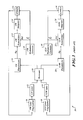
- FIG. 1 illustrates a conventional RFOG 10 consisting of a clockwise (CW) laser 12, a counter-clockwise (CCW) laser 14, a fiber optic resonator 16 and electronic circuits ("electronics") providing at least resonator-coupling and resonance-tracking (or resonance-detection) functionality.
- the CW laser 12 inputs light into the resonator 16 and a CW photodetector 18 detects the CW output of the resonator.
- the resonance frequency is detected by modulating the laser frequency at f 1 using the CW modulation generator 20 and then demodulating the output of the CW photodetector 18 at f 1 using the CW demodulator 22.
- the CW photodetector 18 signal at f 1 passes through zero amplitude.
- the CW integrator 24 controls the laser frequency via the CW laser driver 38 to the resonance frequency by adjusting the laser frequency until the output of the CW demodulator 22 is zero.
- the modulation at f 1 is electronically summed with the CW integrator 24 output by the summing element 26.
- the CCW laser 14 is controlled to the CCW resonance frequency in a similar manner, except it is common that the modulation frequency f 2 is different than f 1 to eliminate errors that arise when light from one direction of propagation in the resonator 16 inadvertently couples into the other direction.
- RFOG RFOG performance
- the IFOG has a unique property called the eigenfrequency, at which rotation sensor errors due to modulation distortion diminish to zero.
- the RFOG does not have an equivalent eigenfrequency. Ultra low distortion electronics help, but are typically not good enough to meet distortion-limiting requirements.
- a method, implementable in a resonator fiber optic gyroscope (RFOG) having a first wave generator configured to produce a first resonance-detection modulating signal at a fundamental resonance frequency includes generating with at least a second wave generator a second modulating signal at an even harmonic of the first modulating signal.
- the second signal is amplitude-modulated (AM) at a frequency that is harmonically unrelated to the first signal.
- the first signal is added to the second signal with a summing element to produce a resonator output bias error signal. An optimum amplitude is determined from the error signal. Subsequently, the amplitude of the first signal is controlled to the optimum amplitude.
- the resonance tracking modulation can be set to a special, or optimum, amplitude where rotation sensing errors due to modulation distortion diminish to zero.
- the following analytical derivation is provided to demonstrate this principle.
- the resonance function is simplified with a polynomial; a perfectly symmetric resonance function is assumed, with only even orders in polynomial.
- the signal represented by Eq. 3 is a bias error since the modulation is set to be centered with the resonance function.
- Eq. 4 represents the optimum amplitude.
- the optimum amplitude has a small dependence on the second harmonic modulation amplitude.
- the second harmonic modulation amplitude can be made very small compared to the modulation amplitude at the fundamental frequency.
- the following is a very good approximation: a 1 ⁇ k 2 2 ⁇ k 4 a z ⁇ ⁇ a 1
- this optimum amplitude may drift due to environmental changes and aging of the gyro components. There is a need to determine the optimum amplitude during normal gyro operation so that the modulation amplitude can be maintained at the optimum amplitude.
- an error signal is created that is indicative of deviations away from the optimum resonance tracking modulation amplitude for zero rotation errors due to distortion.
- the error signal then can be used by a servo, for example, to control the resonance tracking modulation amplitude to the optimum value.
- An embodiment of the invention involves adding to the primary resonance tracking modulation signal an amplitude modulated signal that is at an even harmonic of the primary modulation signal. This creates an error signal in the gyro rate output with a frequency of the amplitude modulation and an amplitude that is indicative of deviations away from the optimum resonance tracking modulation amplitude.
- a servo uses the error signal to control the amplitude of the resonance tracking modulation to the optimum amplitude by driving the error signal to zero.
- Embodiments of the invention may be described in the general context of computer-executable instructions, such as program modules, executed by one or more computer processors or other devices.
- program modules include routines, programs, objects, components, data structures, etc. that perform particular tasks or implement particular abstract data types.
- functionality of the program modules may be combined or distributed as desired in various embodiments.
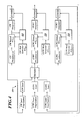
- FIG. 2 illustrates an RFOG 200 according to an embodiment of the invention. Elements of the RFOG 200 illustrated in Figure 2 similar or identical to those elements illustrated in Figure 1 are designated with like reference numerals.
- the RFOG illustrated in FIG. 2 may include or otherwise utilize at least some form of computer readable media, which may be associated with one or more processors and/or memory devices.
- Computer readable media can be any available media that can be accessed by one or more components of such operating environment.
- Computer readable media may comprise computer storage media and communication media.
- Computer storage media includes volatile and nonvolatile, removable and non-removable media implemented in any method or technology for storage of information such as computer readable instructions, data structures, program modules or other data.
- Computer storage media includes, but is not limited to, RAM, ROM, EEPROM, flash memory or other memory technology, CD-ROM, digital versatile disks (DVD) or other optical storage, magnetic cassettes, magnetic tape, magnetic disk storage or other magnetic storage devices, or any other medium which can be used to store the desired information and which can be accessed by one or more components of such operating environment.
- Communication media typically embodies computer readable instructions, data structures, program modules or other data in a modulated data signal such as a carrier wave or other transport mechanism and includes any information delivery media.
- modulated data signal means a signal that has one or more of its characteristics set or changed in such a manner as to encode information in the signal.
- communication media includes wired media such as a wired network or direct-wired connection, and wireless media such as acoustic, RF, infrared and other wireless media. Combinations of the any of the above should also be included within the scope of computer readable media.
- an embodiment includes respective error-control circuits 210, 220 employed in the CW and CCW paths of the RFOG 200.
- Each of the circuits includes a distortion-detection and servo (DD&S or DDS) component 310, a modulation-control (MC) component 320 and an amplitude-modulated second-harmonic-generator (AMSHG) component 330.
- D&S or DDS distortion-detection and servo
- MC modulation-control
- AMSHG amplitude-modulated second-harmonic-generator
- the AMSHG component 330 is configured to inject a small modulation signal at the second harmonic of the resonance tracking modulation signal generated by CW modulation generator 20 and amplitude modulated at a frequency that is not harmonically related to the resonance tracking modulation.
- the AMSHG component 330 may include independent generator elements 360, 370 to provide the respective components of the injected signal.
- This injected signal is, along with the signal generated by CW modulation generator 20, amplified by gain elements associated with the MC component 320 and summed by summing element 26.
- CW demodulator 22 will output a DC signal that is proportional to the amplitude of the signal shown in Eq. 7. Then, if the resonance tracking loop is closed by connecting the CW integrator 24 output to the summer 26, the integrator will generate a signal that will control the CW laser slightly off resonance such that the intended resonance tracking modulation over one side of the resonance peak will generate a signal having an amplitude that is equal and opposite to the amplitude shown in Eq. 7, thus canceling the signal shown in Eq. 7 and resulting in a null at the demodulator 22 output. The frequency deviation away from the resonance frequency will result in rate bias error that is proportional to the amplitude of the signal shown in Eq. 7.
- the laser frequency has a modulation component at an amplitude-modulated second harmonic frequency modulation. Laser light with this frequency modulation component passes through the resonator, which produces a resonator optical output signal that occurs at the resonance tracking modulation frequency with an amplitude modulation at the angular frequency of co"".
- the CW photodetector 18 converts the resonator optical output to a voltage signal that is demodulated by the demodulator 22.
- the signal input to demodulator 22 resulting from the combination of the intended amplitude-modulated second harmonic signal, the unintended second harmonic distortion modulation and the resonance tracking modulation that oscillates at the modulation frequency and is amplitude modulated at the AM frequency is: y ⁇
- ⁇ ⁇ ⁇ am - k 2 ⁇ a 1 ⁇ a 3 + 2 ⁇ k 4 ⁇ a 1 3 ⁇ a 3 + 9 2 ⁇ k 4 ⁇ a 1 ⁇ a 2 2 ⁇ a 3 + 9 8 ⁇ k 4 ⁇ a 1 ⁇ a 3 2 ⁇ sin ⁇ am ⁇ t ⁇ sin ⁇ t
- This signal of Eq. 8 is first demodulated at the resonance tracking modulation frequency by CW demodulator 22 and then demodulated again at the AM frequency by an AM demodulator 340 associated with DDS component 310.
- the output of the second demodulator 340 will be a DC signal that is proportional to the amplitude of the signal shown in Eq. 8.
- the two bias error signals go to zero at the same resonance tracking modulation amplitude (i.e., optimum amplitude): y ⁇
- a servo element 350 associated with the DDS component 310 is configured to determine this optimum amplitude from the error function represented in Eq. 10, and set the amplitude of the resonance tracking signal to this optimum amplitude. As such, the servo element 350 functions to control the amplitude of the resonance tracking modulation by controlling to zero the error signal due to the AM second harmonic modulation, which results in the bias error due to the unintended second harmonic modulation being controlled to zero.
- FIG. 4 illustrates an alternative embodiment RFOG 400 including a CCW path additional to, but otherwise similar to, that of the RFOG 200 illustrated in Figure 2 .
- the RFOG 400 includes error-control circuits 210, 220, 230, similar or identical in functionality to those illustrated in and described with reference to Figure 2 , respectively incorporated within the CW and CCW paths of RFOG 400.
- a third laser is added to implement a scheme for eliminating backscatter errors. Details of this scheme can be found in U.S. Patent No. 7372574 , which is incorporated herein by reference.
Landscapes
- Physics & Mathematics (AREA)
- Engineering & Computer Science (AREA)
- Optics & Photonics (AREA)
- Electromagnetism (AREA)
- Power Engineering (AREA)
- General Physics & Mathematics (AREA)
- Radar, Positioning & Navigation (AREA)
- Remote Sensing (AREA)
- Gyroscopes (AREA)
Abstract
Description
- The resonator fiber optic gyroscope (RFOG) has potential fulfilling needs across many gyro and inertial navigation markets because of its high performance in a small size and at low cost.
Figure 1 illustrates a conventional RFOG 10 consisting of a clockwise (CW)laser 12, a counter-clockwise (CCW)laser 14, a fiberoptic resonator 16 and electronic circuits ("electronics") providing at least resonator-coupling and resonance-tracking (or resonance-detection) functionality. TheCW laser 12 inputs light into theresonator 16 and aCW photodetector 18 detects the CW output of the resonator. - The electronics downstream of the
CW photodetector 18, which include aCW modulation generator 20, aCW demodulator 22, aCW integrator 24, and asumming element 26, control the CW laser frequency to a resonance frequency of theresonator 16. The resonance frequency is detected by modulating the laser frequency at f1 using theCW modulation generator 20 and then demodulating the output of theCW photodetector 18 at f 1 using theCW demodulator 22. At the resonance frequency, theCW photodetector 18 signal at f 1 passes through zero amplitude. TheCW integrator 24 controls the laser frequency via theCW laser driver 38 to the resonance frequency by adjusting the laser frequency until the output of theCW demodulator 22 is zero. The modulation at f 1 is electronically summed with theCW integrator 24 output by thesumming element 26. TheCCW laser 14 is controlled to the CCW resonance frequency in a similar manner, except it is common that the modulation frequency f 2 is different than f 1 to eliminate errors that arise when light from one direction of propagation in theresonator 16 inadvertently couples into the other direction. - One major limitation of RFOG performance comes from distortion of a modulation required for rotation sensing. The IFOG has a unique property called the eigenfrequency, at which rotation sensor errors due to modulation distortion diminish to zero. The RFOG does not have an equivalent eigenfrequency. Ultra low distortion electronics help, but are typically not good enough to meet distortion-limiting requirements.
- In an embodiment, a method, implementable in a resonator fiber optic gyroscope (RFOG) having a first wave generator configured to produce a first resonance-detection modulating signal at a fundamental resonance frequency, includes generating with at least a second wave generator a second modulating signal at an even harmonic of the first modulating signal. The second signal is amplitude-modulated (AM) at a frequency that is harmonically unrelated to the first signal. The first signal is added to the second signal with a summing element to produce a resonator output bias error signal. An optimum amplitude is determined from the error signal. Subsequently, the amplitude of the first signal is controlled to the optimum amplitude.
- Preferred and alternative embodiments of the present invention are described in detail below with reference to the following drawings.
-
Figure 1 illustrates a convention RFOG; -
Figure 2 illustrates an RFOG according to an embodiment of the invention; -
Figure 3 illustrates components of the RFOG ofFigure 2 ; and -
Figure 4 illustrates an RFOG according to an alternative embodiment of the invention. - In an embodiment, the resonance tracking modulation can be set to a special, or optimum, amplitude where rotation sensing errors due to modulation distortion diminish to zero. The following analytical derivation is provided to demonstrate this principle. The resonance function is simplified with a polynomial; a perfectly symmetric resonance function is assumed, with only even orders in polynomial. As shown in Eq. 1, a fourth order polynomial with a minus sign is employed to approximate a resonance function that has a second derivative that changes sign:

- Modulation at the fundamental frequency and a second harmonic yields:

- The component of y that oscillates at the fundamental frequency is given at Eq. 3. This is the resonator output signal at the fundamental frequency, assuming sine wave demodulation:

- The signal represented by Eq. 3 is a bias error since the modulation is set to be centered with the resonance function. The bias error goes to zero when the amplitude of the modulation is:

- Eq. 4 represents the optimum amplitude. The optimum amplitude has a small dependence on the second harmonic modulation amplitude. However, the second harmonic modulation amplitude can be made very small compared to the modulation amplitude at the fundamental frequency. For small second harmonic modulation amplitudes, the following is a very good approximation:

- However, over time, this optimum amplitude may drift due to environmental changes and aging of the gyro components. There is a need to determine the optimum amplitude during normal gyro operation so that the modulation amplitude can be maintained at the optimum amplitude.
- In an embodiment of the invention, by employing certain modulation and demodulation processes, an error signal is created that is indicative of deviations away from the optimum resonance tracking modulation amplitude for zero rotation errors due to distortion. The error signal then can be used by a servo, for example, to control the resonance tracking modulation amplitude to the optimum value.
- An embodiment of the invention involves adding to the primary resonance tracking modulation signal an amplitude modulated signal that is at an even harmonic of the primary modulation signal. This creates an error signal in the gyro rate output with a frequency of the amplitude modulation and an amplitude that is indicative of deviations away from the optimum resonance tracking modulation amplitude. A servo uses the error signal to control the amplitude of the resonance tracking modulation to the optimum amplitude by driving the error signal to zero.
- Embodiments of the invention may be described in the general context of computer-executable instructions, such as program modules, executed by one or more computer processors or other devices. Generally, program modules include routines, programs, objects, components, data structures, etc. that perform particular tasks or implement particular abstract data types. Typically the functionality of the program modules may be combined or distributed as desired in various embodiments.
-
Figure 2 illustrates anRFOG 200 according to an embodiment of the invention. Elements of theRFOG 200 illustrated inFigure 2 similar or identical to those elements illustrated inFigure 1 are designated with like reference numerals. The RFOG illustrated inFIG. 2 may include or otherwise utilize at least some form of computer readable media, which may be associated with one or more processors and/or memory devices. Computer readable media can be any available media that can be accessed by one or more components of such operating environment. By way of example, and not limitation, computer readable media may comprise computer storage media and communication media. Computer storage media includes volatile and nonvolatile, removable and non-removable media implemented in any method or technology for storage of information such as computer readable instructions, data structures, program modules or other data. Computer storage media includes, but is not limited to, RAM, ROM, EEPROM, flash memory or other memory technology, CD-ROM, digital versatile disks (DVD) or other optical storage, magnetic cassettes, magnetic tape, magnetic disk storage or other magnetic storage devices, or any other medium which can be used to store the desired information and which can be accessed by one or more components of such operating environment. Communication media typically embodies computer readable instructions, data structures, program modules or other data in a modulated data signal such as a carrier wave or other transport mechanism and includes any information delivery media. The term "modulated data signal" means a signal that has one or more of its characteristics set or changed in such a manner as to encode information in the signal. By way of example, and not limitation, communication media includes wired media such as a wired network or direct-wired connection, and wireless media such as acoustic, RF, infrared and other wireless media. Combinations of the any of the above should also be included within the scope of computer readable media. - Referring to
Figures 2 and3 , an embodiment includes respective error-control circuits RFOG 200. Each of the circuits includes a distortion-detection and servo (DD&S or DDS)component 310, a modulation-control (MC)component 320 and an amplitude-modulated second-harmonic-generator (AMSHG)component 330. - For ease of illustration, the following discussion is presented in the context of the CW path and its constituent elements illustrated in
Figure 2 . It is to be understood that the same or similar principles apply equally to the CCW path illustrated inFigure 2 , as well as the CCW paths illustrated inFigure 4 . As best illustrated inFigure 3 , theAMSHG component 330 is configured to inject a small modulation signal at the second harmonic of the resonance tracking modulation signal generated byCW modulation generator 20 and amplitude modulated at a frequency that is not harmonically related to the resonance tracking modulation. TheAMSHG component 330 may includeindependent generator elements CW modulation generator 20, amplified by gain elements associated with theMC component 320 and summed by summingelement 26. The resultant signal is given in Eq. 6:
where the first right-hand term is the intended modulation at the fundamental frequency fl, the second term is the unintended modulation at the second harmonic of the fundamental frequency, and the third term is the intended AM modulated signal at the second harmonic. - The component of y that oscillates only at the fundamental frequency is given at Eq. 7. This is the resonator output signal (bias error) at the fundamental frequency:

- If the
CW laser 12 frequency is exactly on resonance, and the resonance tracking feedback loop is opened by disconnectingCW integrator 24 output from the corresponding input tosummer 26, thenCW demodulator 22 will output a DC signal that is proportional to the amplitude of the signal shown in Eq. 7. Then, if the resonance tracking loop is closed by connecting theCW integrator 24 output to thesummer 26, the integrator will generate a signal that will control the CW laser slightly off resonance such that the intended resonance tracking modulation over one side of the resonance peak will generate a signal having an amplitude that is equal and opposite to the amplitude shown in Eq. 7, thus canceling the signal shown in Eq. 7 and resulting in a null at thedemodulator 22 output. The frequency deviation away from the resonance frequency will result in rate bias error that is proportional to the amplitude of the signal shown in Eq. 7. - The amplitude-modulated second harmonic modulation signal applied by the
AMSHG component 330 that is combined with the resonance tracking modulation signal at themodulation control component 320, passes through thesummer 26, and to the CW laserCW frequency control 38, which modulates the laser frequency. The laser frequency has a modulation component at an amplitude-modulated second harmonic frequency modulation. Laser light with this frequency modulation component passes through the resonator, which produces a resonator optical output signal that occurs at the resonance tracking modulation frequency with an amplitude modulation at the angular frequency of co"". TheCW photodetector 18 converts the resonator optical output to a voltage signal that is demodulated by thedemodulator 22. The signal input todemodulator 22 resulting from the combination of the intended amplitude-modulated second harmonic signal, the unintended second harmonic distortion modulation and the resonance tracking modulation that oscillates at the modulation frequency and is amplitude modulated at the AM frequency is:
- This signal of Eq. 8 is first demodulated at the resonance tracking modulation frequency by
CW demodulator 22 and then demodulated again at the AM frequency by anAM demodulator 340 associated withDDS component 310. The output of thesecond demodulator 340 will be a DC signal that is proportional to the amplitude of the signal shown in Eq. 8. - If the unintended and intended second harmonic modulation amplitudes are assumed to be very small compared to the resonance tracking modulation amplitude, the higher order terms can be neglected, such that:


where Eq. 9 represents the bias error from the unintended second harmonic modulation, and Eq. 10 represents the bias error from the intended second harmonic modulation. - The two bias error signals go to zero at the same resonance tracking modulation amplitude (i.e., optimum amplitude):


- A
servo element 350 associated with theDDS component 310 is configured to determine this optimum amplitude from the error function represented in Eq. 10, and set the amplitude of the resonance tracking signal to this optimum amplitude. As such, theservo element 350 functions to control the amplitude of the resonance tracking modulation by controlling to zero the error signal due to the AM second harmonic modulation, which results in the bias error due to the unintended second harmonic modulation being controlled to zero. -
Figure 4 illustrates an alternative embodiment RFOG 400 including a CCW path additional to, but otherwise similar to, that of theRFOG 200 illustrated inFigure 2 . The RFOG 400 includes error-control circuits Figure 2 , respectively incorporated within the CW and CCW paths of RFOG 400. For the configuration shown inFig. 4 , a third laser is added to implement a scheme for eliminating backscatter errors. Details of this scheme can be found inU.S. Patent No. 7372574 , which is incorporated herein by reference. - While a preferred embodiment of the invention has been illustrated and described, as noted above, many changes can be made without departing from the spirit and scope of the invention. Accordingly, the scope of the invention is not limited by the disclosure of the preferred embodiment. Instead, the invention should be determined entirely by reference to the claims that follow.
Claims (10)
- A method implementable in a resonator fiber optic gyroscope (RFOG) (200) having a first wave generator (20) configured to produce a first resonance-detection modulating signal at a fundamental frequency, the method comprising the steps of:generating with at least a second wave generator (30) a second modulating signal at an even harmonic of the first modulating signal, the second signal being amplitude-modulated;adding with a summing element (36) the first signal to the second signal to produce a resonator output bias error signal;determining an optimum amplitude from the error signal; andsetting the amplitude of the first signal to the optimum amplitude.
- The method of claim 1, further comprising the steps of:prior to determining the optimum amplitude, demodulating the error signal at the first-signal frequency; andprior to determining the optimum amplitude, demodulating the error signal at the second-signal frequency.
- The method of claim 2 wherein the error signal is demodulated at the first-signal frequency prior to demodulating the error signal at the second-signal frequency.
- An error-control circuit (210, 220, 310, 320) implementable in a resonator fiber optic gyroscope (RFOG) (200, 400), the RFOG including a first wave generator (20) configured to produce a first resonance-detection modulating signal at a fundamental resonance frequency, the circuit comprising:at least a second wave generator (30) configured to generate a second modulating signal at an even harmonic of the first modulating signal and provide the second signal to a summing element (36) configured to sum the first and second signals, the second signal being amplitude-modulated (AM) at a frequency that is harmonically unrelated to the first signal; anda servo element (350) configured to determine an optimum amplitude from an error signal produced by the summed first and second signals, the servo element further configured to set the amplitude of the first signal to the optimum amplitude.
- The circuit of claim 4 wherein the error signal is demodulated at the first-signal frequency prior to the optimum amplitude being determined, and further comprising:an AM-demodulating element (32) configured to demodulate the error signal at the second-signal frequency prior to the optimum amplitude being determined.
- The circuit of claim 5 wherein the error signal is demodulated at the first-signal frequency prior to demodulating the error signal at the second-signal frequency.
- The circuit of claim 4 wherein the even harmonic comprises the second harmonic.
- The circuit of claim 4 wherein the second modulating signal comprises:a third signal at the even harmonic of the first modulating signal and generated by the second wave generator; anda fourth signal modulated at the frequency that is harmonically unrelated to the first signal and generated by a third wave generator.
- The circuit of claim 4, further comprising at least one amplifier configured to amplify the first and second signals prior to adding the first and second signals.
- The circuit of claim 4, wherein the circuit is implemented in the resonator fiber optic gyroscope, wherein the resonator fiber optic gyroscope comprises a light source.
Applications Claiming Priority (1)
| Application Number | Priority Date | Filing Date | Title |
|---|---|---|---|
| US12/413,304 US7864328B2 (en) | 2009-03-27 | 2009-03-27 | Determination of optimum modulation amplitude to suppress modulation-distortation-induced rotation sensing errors in a fiber optic gyroscope |
Publications (3)
| Publication Number | Publication Date |
|---|---|
| EP2233885A2 true EP2233885A2 (en) | 2010-09-29 |
| EP2233885A3 EP2233885A3 (en) | 2011-10-05 |
| EP2233885B1 EP2233885B1 (en) | 2012-03-21 |
Family
ID=42229148
Family Applications (1)
| Application Number | Title | Priority Date | Filing Date |
|---|---|---|---|
| EP10154308A Active EP2233885B1 (en) | 2009-03-27 | 2010-02-22 | Determination of optimum modulation amplitude to suppress modulation-distortation-induced rotation sensing errors in a fiber optic gyroscope |
Country Status (4)
| Country | Link |
|---|---|
| US (1) | US7864328B2 (en) |
| EP (1) | EP2233885B1 (en) |
| JP (1) | JP5537210B2 (en) |
| AT (1) | ATE550629T1 (en) |
Cited By (1)
| Publication number | Priority date | Publication date | Assignee | Title |
|---|---|---|---|---|
| EP3605020A1 (en) * | 2018-08-01 | 2020-02-05 | Honeywell International Inc. | Resonator fiber-optic gyro with quadrature error reducer |
Families Citing this family (13)
| Publication number | Priority date | Publication date | Assignee | Title |
|---|---|---|---|---|
| US8223341B2 (en) * | 2010-05-28 | 2012-07-17 | Honeywell International Inc. | System and method for enhancing signal-to-noise ratio of a resonator fiber optic gyroscope |
| JP5429494B2 (en) * | 2010-07-20 | 2014-02-26 | 横河電機株式会社 | Multi-channel photometric measuring device |
| US8213019B2 (en) | 2010-09-07 | 2012-07-03 | Honeywell International Inc. | RFOG with optical heterodyning for optical signal discrimination |
| US8908187B2 (en) * | 2011-11-02 | 2014-12-09 | Honeywell International Inc. | System and method for reducing errors in a resonator fiber optic gyroscope |
| US8659760B2 (en) * | 2012-04-12 | 2014-02-25 | Honeywell International Inc. | Resonator fiber optic gyroscope utilizing laser frequency combs |
| US8830479B2 (en) * | 2013-01-28 | 2014-09-09 | Honeywell International Inc. | RFOG with optical heterodyning for optical signal discrimination |
| US8947671B2 (en) | 2013-02-22 | 2015-02-03 | Honeywell International Inc. | Method and system for detecting optical ring resonator resonance frequencies and free spectral range to reduce the number of lasers in a resonator fiber optic gyroscope |
| US9008221B2 (en) | 2013-04-01 | 2015-04-14 | Honeywell International Inc. | Spurious frequency attenuation servo |
| US9001336B1 (en) | 2013-10-07 | 2015-04-07 | Honeywell International Inc. | Methods and apparatus of tracking/locking resonator free spectral range and its application in resonator fiber optic gyroscope |
| US9121708B1 (en) | 2014-05-08 | 2015-09-01 | Honeywell International Inc. | Resonator fiber optic gyroscope without frequency overlap in sideband-heterodyne-detection modulations |
| RU2637186C1 (en) * | 2016-05-25 | 2017-11-30 | Акционерное общество "Концерн "Центральный научно-исследовательский институт "Электроприбор" | Method of determination of two-stage gyro unit error |
| JP6540670B2 (en) * | 2016-11-29 | 2019-07-10 | 横河電機株式会社 | Signal detection device and optical characteristic measurement device |
| US10175047B2 (en) | 2017-05-10 | 2019-01-08 | Honeywell International Inc. | Systems and methods for dynamic bias offset operation in resonator fiber optic gyroscope |
Citations (1)
| Publication number | Priority date | Publication date | Assignee | Title |
|---|---|---|---|---|
| US7372574B2 (en) | 2005-12-09 | 2008-05-13 | Honeywell International Inc. | System and method for stabilizing light sources in resonator gyro |
Family Cites Families (14)
| Publication number | Priority date | Publication date | Assignee | Title |
|---|---|---|---|---|
| US6014217A (en) * | 1991-10-30 | 2000-01-11 | Honeywell, Inc. | Fiber optic gyroscope scattering error reduction |
| US5296912A (en) | 1992-01-16 | 1994-03-22 | Honeywell Inc. | RFOG rotation rate error reducer having resonator mode symmetrization |
| US5283626A (en) * | 1992-04-17 | 1994-02-01 | Honeywell Inc. | Fiber optic gyroscope bias modulation amplitude determination with reset means |
| JPH063155A (en) * | 1992-06-19 | 1994-01-11 | Sumitomo Electric Ind Ltd | Fiber-optic gyro |
| US5296902A (en) * | 1992-07-06 | 1994-03-22 | Michlin Steven B | Apparatus and method for providing a removable seal between the toner hopper and feed roller compartment of a toner cartridge assembly |
| US5363195A (en) * | 1992-12-24 | 1994-11-08 | The Charles Stark Draper Laboratory, Inc. | Automatic gain calibration system for a phase modulator in a fiber optic gyro |
| US5351252A (en) * | 1993-02-26 | 1994-09-27 | The Board Of Trustees Of The Leland Stanford University | Technique of reducing the Kerr effect and extending the dynamic range in a Brillouin fiber optic gyroscope |
| JP2791412B2 (en) * | 1993-03-18 | 1998-08-27 | 日本航空電子工業株式会社 | Optical resonance angular velocity meter |
| JP2840985B2 (en) * | 1993-04-21 | 1998-12-24 | ハネウエル・インコーポレーテッド | Fiber optic gyroscope |
| US5537671A (en) * | 1995-02-10 | 1996-07-16 | The Board Of Trustees Of The Leland Stanford Junior University | Technique of reducing the Kerr effect and extending the dynamic range in a brillouin fiber optic gyroscope |
| JP2003028651A (en) * | 2001-07-16 | 2003-01-29 | Japan Aviation Electronics Industry Ltd | Light interference angular velocity meter |
| JP5351451B2 (en) * | 2007-07-06 | 2013-11-27 | ハネウェル・インターナショナル・インコーポレーテッド | RFOG modulation error correction |
| US7855789B2 (en) * | 2007-07-06 | 2010-12-21 | Honeywell International Inc. | RFOG modulation error correction |
| US8065087B2 (en) * | 2009-01-30 | 2011-11-22 | Gyrodata, Incorporated | Reducing error contributions to gyroscopic measurements from a wellbore survey system |
-
2009
- 2009-03-27 US US12/413,304 patent/US7864328B2/en active Active
-
2010
- 2010-02-22 AT AT10154308T patent/ATE550629T1/en active
- 2010-02-22 EP EP10154308A patent/EP2233885B1/en active Active
- 2010-03-25 JP JP2010069886A patent/JP5537210B2/en not_active Expired - Fee Related
Patent Citations (1)
| Publication number | Priority date | Publication date | Assignee | Title |
|---|---|---|---|---|
| US7372574B2 (en) | 2005-12-09 | 2008-05-13 | Honeywell International Inc. | System and method for stabilizing light sources in resonator gyro |
Cited By (2)
| Publication number | Priority date | Publication date | Assignee | Title |
|---|---|---|---|---|
| EP3605020A1 (en) * | 2018-08-01 | 2020-02-05 | Honeywell International Inc. | Resonator fiber-optic gyro with quadrature error reducer |
| US10746550B2 (en) | 2018-08-01 | 2020-08-18 | Honeywell International Inc. | Resonator fiber-optic gyro with quadrature error reducer |
Also Published As
| Publication number | Publication date |
|---|---|
| EP2233885A3 (en) | 2011-10-05 |
| EP2233885B1 (en) | 2012-03-21 |
| JP2010230673A (en) | 2010-10-14 |
| US20100245834A1 (en) | 2010-09-30 |
| US7864328B2 (en) | 2011-01-04 |
| JP5537210B2 (en) | 2014-07-02 |
| ATE550629T1 (en) | 2012-04-15 |
Similar Documents
| Publication | Publication Date | Title |
|---|---|---|
| EP2233885B1 (en) | Determination of optimum modulation amplitude to suppress modulation-distortation-induced rotation sensing errors in a fiber optic gyroscope | |
| JP5480950B2 (en) | System and method for resonator fiber optic gyroscope intensity modulation control | |
| US9772189B2 (en) | Systems and methods for resonance switching resonator fiber optic gyroscopes (RFOGs) with feed-forward processing | |
| JP6404656B2 (en) | Method and apparatus for tracking / rocking the free spectral range of a resonator and its application to a resonator fiber optic gyroscope | |
| EP2390625B1 (en) | System and method for enhancing signal-to-noise ratio of a resonator fiber optic gyroscope | |
| US8908187B2 (en) | System and method for reducing errors in a resonator fiber optic gyroscope | |
| US7216525B2 (en) | Method for compensation for a zero error in a coriolis gyro | |
| US5325174A (en) | Integrated optic gyro with one Bragg transducer | |
| US8379216B2 (en) | Solid state gyrolaser with controlled optical pumping | |
| US7869052B2 (en) | Method and amplifying stage for suppressing modulation distortion rate sensing errors in a resonator fiber optic gyroscope | |
| US5237387A (en) | Dual serrodyne resonator fiber optic gyroscope | |
| EP2958254A1 (en) | Controlled modulation of light beam with highly stable suppression of carrier or sidebands | |
| NO840079L (en) | LASER GYRO | |
| CA2021073A1 (en) | Dual serrodyne resonator fiber optic gyroscope | |
| US5100236A (en) | Two servo loop passive ring laser gyroscope | |
| EP3617648B1 (en) | Hyperbolic modulation offset error reducer for an rfog | |
| Mao et al. | Resonator micro-optic gyroscope based on the double phase modulation technique | |
| US5438411A (en) | Electronic phase-tracking open-loop fiber optic gyroscope | |
| JPH05508222A (en) | Single-stage demodulator using reference signal phase fluctuation method | |
| EP4296616A1 (en) | Modulation methods and systems for non-reciprocal kerr reduction in resonator fiber optic gyroscopes | |
| JP3451230B2 (en) | Resonant optical fiber gyro | |
| PAVLATH | Fiber optic gyro evolution concept to product |
Legal Events
| Date | Code | Title | Description |
|---|---|---|---|
| PUAI | Public reference made under article 153(3) epc to a published international application that has entered the european phase |
Free format text: ORIGINAL CODE: 0009012 |
|
| 17P | Request for examination filed |
Effective date: 20100222 |
|
| AK | Designated contracting states |
Kind code of ref document: A2 Designated state(s): AT BE BG CH CY CZ DE DK EE ES FI FR GB GR HR HU IE IS IT LI LT LU LV MC MK MT NL NO PL PT RO SE SI SK SM TR |
|
| AX | Request for extension of the european patent |
Extension state: AL BA RS |
|
| PUAL | Search report despatched |
Free format text: ORIGINAL CODE: 0009013 |
|
| AK | Designated contracting states |
Kind code of ref document: A3 Designated state(s): AT BE BG CH CY CZ DE DK EE ES FI FR GB GR HR HU IE IS IT LI LT LU LV MC MK MT NL NO PL PT RO SE SI SK SM TR |
|
| AX | Request for extension of the european patent |
Extension state: AL BA RS |
|
| RIC1 | Information provided on ipc code assigned before grant |
Ipc: G01C 19/72 20060101AFI20110830BHEP |
|
| GRAP | Despatch of communication of intention to grant a patent |
Free format text: ORIGINAL CODE: EPIDOSNIGR1 |
|
| GRAS | Grant fee paid |
Free format text: ORIGINAL CODE: EPIDOSNIGR3 |
|
| GRAA | (expected) grant |
Free format text: ORIGINAL CODE: 0009210 |
|
| AK | Designated contracting states |
Kind code of ref document: B1 Designated state(s): AT BE BG CH CY CZ DE DK EE ES FI FR GB GR HR HU IE IS IT LI LT LU LV MC MK MT NL NO PL PT RO SE SI SK SM TR |
|
| REG | Reference to a national code |
Ref country code: GB Ref legal event code: FG4D |
|
| REG | Reference to a national code |
Ref country code: CH Ref legal event code: EP |
|
| REG | Reference to a national code |
Ref country code: IE Ref legal event code: FG4D |
|
| REG | Reference to a national code |
Ref country code: AT Ref legal event code: REF Ref document number: 550629 Country of ref document: AT Kind code of ref document: T Effective date: 20120415 |
|
| REG | Reference to a national code |
Ref country code: DE Ref legal event code: R096 Ref document number: 602010001081 Country of ref document: DE Effective date: 20120516 |
|
| REG | Reference to a national code |
Ref country code: NL Ref legal event code: VDEP Effective date: 20120321 |
|
| PG25 | Lapsed in a contracting state [announced via postgrant information from national office to epo] |
Ref country code: HR Free format text: LAPSE BECAUSE OF FAILURE TO SUBMIT A TRANSLATION OF THE DESCRIPTION OR TO PAY THE FEE WITHIN THE PRESCRIBED TIME-LIMIT Effective date: 20120321 Ref country code: LT Free format text: LAPSE BECAUSE OF FAILURE TO SUBMIT A TRANSLATION OF THE DESCRIPTION OR TO PAY THE FEE WITHIN THE PRESCRIBED TIME-LIMIT Effective date: 20120321 Ref country code: NO Free format text: LAPSE BECAUSE OF FAILURE TO SUBMIT A TRANSLATION OF THE DESCRIPTION OR TO PAY THE FEE WITHIN THE PRESCRIBED TIME-LIMIT Effective date: 20120621 |
|
| LTIE | Lt: invalidation of european patent or patent extension |
Effective date: 20120321 |
|
| PG25 | Lapsed in a contracting state [announced via postgrant information from national office to epo] |
Ref country code: FI Free format text: LAPSE BECAUSE OF FAILURE TO SUBMIT A TRANSLATION OF THE DESCRIPTION OR TO PAY THE FEE WITHIN THE PRESCRIBED TIME-LIMIT Effective date: 20120321 Ref country code: GR Free format text: LAPSE BECAUSE OF FAILURE TO SUBMIT A TRANSLATION OF THE DESCRIPTION OR TO PAY THE FEE WITHIN THE PRESCRIBED TIME-LIMIT Effective date: 20120622 Ref country code: LV Free format text: LAPSE BECAUSE OF FAILURE TO SUBMIT A TRANSLATION OF THE DESCRIPTION OR TO PAY THE FEE WITHIN THE PRESCRIBED TIME-LIMIT Effective date: 20120321 |
|
| REG | Reference to a national code |
Ref country code: AT Ref legal event code: MK05 Ref document number: 550629 Country of ref document: AT Kind code of ref document: T Effective date: 20120321 |
|
| PG25 | Lapsed in a contracting state [announced via postgrant information from national office to epo] |
Ref country code: CY Free format text: LAPSE BECAUSE OF FAILURE TO SUBMIT A TRANSLATION OF THE DESCRIPTION OR TO PAY THE FEE WITHIN THE PRESCRIBED TIME-LIMIT Effective date: 20120321 |
|
| PG25 | Lapsed in a contracting state [announced via postgrant information from national office to epo] |
Ref country code: IS Free format text: LAPSE BECAUSE OF FAILURE TO SUBMIT A TRANSLATION OF THE DESCRIPTION OR TO PAY THE FEE WITHIN THE PRESCRIBED TIME-LIMIT Effective date: 20120721 Ref country code: SE Free format text: LAPSE BECAUSE OF FAILURE TO SUBMIT A TRANSLATION OF THE DESCRIPTION OR TO PAY THE FEE WITHIN THE PRESCRIBED TIME-LIMIT Effective date: 20120321 Ref country code: PL Free format text: LAPSE BECAUSE OF FAILURE TO SUBMIT A TRANSLATION OF THE DESCRIPTION OR TO PAY THE FEE WITHIN THE PRESCRIBED TIME-LIMIT Effective date: 20120321 Ref country code: CZ Free format text: LAPSE BECAUSE OF FAILURE TO SUBMIT A TRANSLATION OF THE DESCRIPTION OR TO PAY THE FEE WITHIN THE PRESCRIBED TIME-LIMIT Effective date: 20120321 Ref country code: SI Free format text: LAPSE BECAUSE OF FAILURE TO SUBMIT A TRANSLATION OF THE DESCRIPTION OR TO PAY THE FEE WITHIN THE PRESCRIBED TIME-LIMIT Effective date: 20120321 Ref country code: BE Free format text: LAPSE BECAUSE OF FAILURE TO SUBMIT A TRANSLATION OF THE DESCRIPTION OR TO PAY THE FEE WITHIN THE PRESCRIBED TIME-LIMIT Effective date: 20120321 Ref country code: RO Free format text: LAPSE BECAUSE OF FAILURE TO SUBMIT A TRANSLATION OF THE DESCRIPTION OR TO PAY THE FEE WITHIN THE PRESCRIBED TIME-LIMIT Effective date: 20120321 Ref country code: EE Free format text: LAPSE BECAUSE OF FAILURE TO SUBMIT A TRANSLATION OF THE DESCRIPTION OR TO PAY THE FEE WITHIN THE PRESCRIBED TIME-LIMIT Effective date: 20120321 |
|
| PG25 | Lapsed in a contracting state [announced via postgrant information from national office to epo] |
Ref country code: SK Free format text: LAPSE BECAUSE OF FAILURE TO SUBMIT A TRANSLATION OF THE DESCRIPTION OR TO PAY THE FEE WITHIN THE PRESCRIBED TIME-LIMIT Effective date: 20120321 Ref country code: PT Free format text: LAPSE BECAUSE OF FAILURE TO SUBMIT A TRANSLATION OF THE DESCRIPTION OR TO PAY THE FEE WITHIN THE PRESCRIBED TIME-LIMIT Effective date: 20120723 |
|
| PLBE | No opposition filed within time limit |
Free format text: ORIGINAL CODE: 0009261 |
|
| STAA | Information on the status of an ep patent application or granted ep patent |
Free format text: STATUS: NO OPPOSITION FILED WITHIN TIME LIMIT |
|
| PG25 | Lapsed in a contracting state [announced via postgrant information from national office to epo] |
Ref country code: AT Free format text: LAPSE BECAUSE OF FAILURE TO SUBMIT A TRANSLATION OF THE DESCRIPTION OR TO PAY THE FEE WITHIN THE PRESCRIBED TIME-LIMIT Effective date: 20120321 Ref country code: DK Free format text: LAPSE BECAUSE OF FAILURE TO SUBMIT A TRANSLATION OF THE DESCRIPTION OR TO PAY THE FEE WITHIN THE PRESCRIBED TIME-LIMIT Effective date: 20120321 Ref country code: NL Free format text: LAPSE BECAUSE OF FAILURE TO SUBMIT A TRANSLATION OF THE DESCRIPTION OR TO PAY THE FEE WITHIN THE PRESCRIBED TIME-LIMIT Effective date: 20120321 |
|
| 26N | No opposition filed |
Effective date: 20130102 |
|
| PG25 | Lapsed in a contracting state [announced via postgrant information from national office to epo] |
Ref country code: IT Free format text: LAPSE BECAUSE OF FAILURE TO SUBMIT A TRANSLATION OF THE DESCRIPTION OR TO PAY THE FEE WITHIN THE PRESCRIBED TIME-LIMIT Effective date: 20120321 |
|
| REG | Reference to a national code |
Ref country code: DE Ref legal event code: R097 Ref document number: 602010001081 Country of ref document: DE Effective date: 20130102 |
|
| PG25 | Lapsed in a contracting state [announced via postgrant information from national office to epo] |
Ref country code: ES Free format text: LAPSE BECAUSE OF FAILURE TO SUBMIT A TRANSLATION OF THE DESCRIPTION OR TO PAY THE FEE WITHIN THE PRESCRIBED TIME-LIMIT Effective date: 20120702 |
|
| PG25 | Lapsed in a contracting state [announced via postgrant information from national office to epo] |
Ref country code: BG Free format text: LAPSE BECAUSE OF FAILURE TO SUBMIT A TRANSLATION OF THE DESCRIPTION OR TO PAY THE FEE WITHIN THE PRESCRIBED TIME-LIMIT Effective date: 20120621 |
|
| PG25 | Lapsed in a contracting state [announced via postgrant information from national office to epo] |
Ref country code: MC Free format text: LAPSE BECAUSE OF NON-PAYMENT OF DUE FEES Effective date: 20130228 |
|
| REG | Reference to a national code |
Ref country code: IE Ref legal event code: MM4A |
|
| PG25 | Lapsed in a contracting state [announced via postgrant information from national office to epo] |
Ref country code: IE Free format text: LAPSE BECAUSE OF NON-PAYMENT OF DUE FEES Effective date: 20130222 |
|
| PG25 | Lapsed in a contracting state [announced via postgrant information from national office to epo] |
Ref country code: MT Free format text: LAPSE BECAUSE OF FAILURE TO SUBMIT A TRANSLATION OF THE DESCRIPTION OR TO PAY THE FEE WITHIN THE PRESCRIBED TIME-LIMIT Effective date: 20120321 |
|
| REG | Reference to a national code |
Ref country code: CH Ref legal event code: PL |
|
| GBPC | Gb: european patent ceased through non-payment of renewal fee |
Effective date: 20140222 |
|
| PG25 | Lapsed in a contracting state [announced via postgrant information from national office to epo] |
Ref country code: CH Free format text: LAPSE BECAUSE OF NON-PAYMENT OF DUE FEES Effective date: 20140228 Ref country code: LI Free format text: LAPSE BECAUSE OF NON-PAYMENT OF DUE FEES Effective date: 20140228 |
|
| PG25 | Lapsed in a contracting state [announced via postgrant information from national office to epo] |
Ref country code: GB Free format text: LAPSE BECAUSE OF NON-PAYMENT OF DUE FEES Effective date: 20140222 |
|
| PG25 | Lapsed in a contracting state [announced via postgrant information from national office to epo] |
Ref country code: SM Free format text: LAPSE BECAUSE OF FAILURE TO SUBMIT A TRANSLATION OF THE DESCRIPTION OR TO PAY THE FEE WITHIN THE PRESCRIBED TIME-LIMIT Effective date: 20120321 |
|
| PG25 | Lapsed in a contracting state [announced via postgrant information from national office to epo] |
Ref country code: TR Free format text: LAPSE BECAUSE OF FAILURE TO SUBMIT A TRANSLATION OF THE DESCRIPTION OR TO PAY THE FEE WITHIN THE PRESCRIBED TIME-LIMIT Effective date: 20120321 |
|
| PG25 | Lapsed in a contracting state [announced via postgrant information from national office to epo] |
Ref country code: HU Free format text: LAPSE BECAUSE OF FAILURE TO SUBMIT A TRANSLATION OF THE DESCRIPTION OR TO PAY THE FEE WITHIN THE PRESCRIBED TIME-LIMIT; INVALID AB INITIO Effective date: 20100222 Ref country code: MK Free format text: LAPSE BECAUSE OF FAILURE TO SUBMIT A TRANSLATION OF THE DESCRIPTION OR TO PAY THE FEE WITHIN THE PRESCRIBED TIME-LIMIT Effective date: 20120321 Ref country code: LU Free format text: LAPSE BECAUSE OF NON-PAYMENT OF DUE FEES Effective date: 20130222 |
|
| REG | Reference to a national code |
Ref country code: FR Ref legal event code: PLFP Year of fee payment: 7 |
|
| REG | Reference to a national code |
Ref country code: FR Ref legal event code: PLFP Year of fee payment: 8 |
|
| REG | Reference to a national code |
Ref country code: FR Ref legal event code: PLFP Year of fee payment: 9 |
|
| PGFP | Annual fee paid to national office [announced via postgrant information from national office to epo] |
Ref country code: DE Payment date: 20200228 Year of fee payment: 11 |
|
| REG | Reference to a national code |
Ref country code: DE Ref legal event code: R119 Ref document number: 602010001081 Country of ref document: DE |
|
| PG25 | Lapsed in a contracting state [announced via postgrant information from national office to epo] |
Ref country code: DE Free format text: LAPSE BECAUSE OF NON-PAYMENT OF DUE FEES Effective date: 20210901 |
|
| PGFP | Annual fee paid to national office [announced via postgrant information from national office to epo] |
Ref country code: FR Payment date: 20230223 Year of fee payment: 14 |
|
| P01 | Opt-out of the competence of the unified patent court (upc) registered |
Effective date: 20230525 |