EP2222932B1 - Hybrid drill bit and design method - Google Patents
Hybrid drill bit and design method Download PDFInfo
- Publication number
- EP2222932B1 EP2222932B1 EP08850570.6A EP08850570A EP2222932B1 EP 2222932 B1 EP2222932 B1 EP 2222932B1 EP 08850570 A EP08850570 A EP 08850570A EP 2222932 B1 EP2222932 B1 EP 2222932B1
- Authority
- EP
- European Patent Office
- Prior art keywords
- cutter
- bit
- fixed blade
- rolling
- cutting element
- Prior art date
- Legal status (The legal status is an assumption and is not a legal conclusion. Google has not performed a legal analysis and makes no representation as to the accuracy of the status listed.)
- Active
Links
- 238000000034 method Methods 0.000 title claims description 19
- 238000005520 cutting process Methods 0.000 claims description 276
- 238000005096 rolling process Methods 0.000 claims description 74
- 230000015572 biosynthetic process Effects 0.000 claims description 38
- 238000005553 drilling Methods 0.000 claims description 30
- 238000005755 formation reaction Methods 0.000 description 36
- 229910003460 diamond Inorganic materials 0.000 description 16
- 239000010432 diamond Substances 0.000 description 16
- 230000035515 penetration Effects 0.000 description 7
- 230000001965 increasing effect Effects 0.000 description 6
- 239000000463 material Substances 0.000 description 6
- 239000011435 rock Substances 0.000 description 6
- UONOETXJSWQNOL-UHFFFAOYSA-N tungsten carbide Chemical compound [W+]#[C-] UONOETXJSWQNOL-UHFFFAOYSA-N 0.000 description 6
- 230000009471 action Effects 0.000 description 4
- 230000008901 benefit Effects 0.000 description 3
- 239000012530 fluid Substances 0.000 description 3
- 229910052751 metal Inorganic materials 0.000 description 3
- 239000002184 metal Substances 0.000 description 3
- 229910000831 Steel Inorganic materials 0.000 description 2
- 230000007423 decrease Effects 0.000 description 2
- 230000003247 decreasing effect Effects 0.000 description 2
- 230000000694 effects Effects 0.000 description 2
- 239000000314 lubricant Substances 0.000 description 2
- 238000004519 manufacturing process Methods 0.000 description 2
- 238000007790 scraping Methods 0.000 description 2
- 239000010959 steel Substances 0.000 description 2
- 239000003082 abrasive agent Substances 0.000 description 1
- 230000002411 adverse Effects 0.000 description 1
- 238000005516 engineering process Methods 0.000 description 1
- 230000002708 enhancing effect Effects 0.000 description 1
- 238000007373 indentation Methods 0.000 description 1
- 239000004579 marble Substances 0.000 description 1
- 239000011159 matrix material Substances 0.000 description 1
- 230000004048 modification Effects 0.000 description 1
- 238000012986 modification Methods 0.000 description 1
- 239000003208 petroleum Substances 0.000 description 1
- 239000007787 solid Substances 0.000 description 1
- 239000000758 substrate Substances 0.000 description 1
- 239000000725 suspension Substances 0.000 description 1
Images


Classifications
-
- E—FIXED CONSTRUCTIONS
- E21—EARTH OR ROCK DRILLING; MINING
- E21B—EARTH OR ROCK DRILLING; OBTAINING OIL, GAS, WATER, SOLUBLE OR MELTABLE MATERIALS OR A SLURRY OF MINERALS FROM WELLS
- E21B10/00—Drill bits
- E21B10/08—Roller bits
- E21B10/14—Roller bits combined with non-rolling cutters other than of leading-portion type
Definitions
- the present invention relates in general to earth-boring bits and, in particular, to an improved bit having a combination of rolling-cutters and fixed cutters and cutting elements and a method of design and operation of such bits.
- rock bits having one, two, or three rolling cutters rotatably mounted thereon are employed.
- the bit is secured to the lower end of a drill string that is rotated from the surface or by downhole motors or turbines.
- the cutters mounted on the bit roll and slide upon the bottom of the borehole as the drill string is rotated, thereby engaging and disintegrating the formation material to be removed.
- the rolling-cutters are provided with cutting elements or teeth that are forced to penetrate and gouge the bottom of the borehole by weight from the drill string.
- the cuttings from the bottom and sides of the borehole are washed away and disposed by drilling fluid that is pumped down from the surface through the hollow, rotating drill string, and the nozzles as orifices on the drill bit. Eventually the cuttings are carried in suspension in the drilling fluid to the surface up the exterior of the drill string.
- Rolling-cutter bits dominated petroleum drilling for the greater part of the 20 th century. With improvements in synthetic diamond technology that occurred in the 1970s and 1980s, the fixed blade cutter bit or drag bit became popular again in the latter part of the 20 th century.
- Modern fixed blade cutter bits are often referred to as “diamond” or “PDC” (polycrystalline diamond cutter bits) bits and are far removed from the original fixed bladecutter bits of the 19 th and early 20 th centuries.
- Diamond or PDC bits carry cutting elements comprising polycrystalline diamond compact layers or "tables" formed on and bonded to a supporting substrate, conventionally of cemented tungsten carbide, the cutting element being arranged in selected location on blades or other structures on the bit body with the diamond tables facing generally in the direction of bit rotation.
- Fixed blade cutter bits have the advantage of being much more aggressive during drilling and therefore drill much faster at equivalent weight-on-bit levels (WOB) than, for instance, a rolling-cutter bit. In addition, they have no moving parts, which make their design less complex and more robust.
- the drilling mechanics and dynamics of fixed blade cutter bits are different from those of rolling-cutter bits precisely because they are more aggressive in cutting and require more torque to rotate during drilling.
- fixed blade cutter bits are used in a manner similar to that for rolling-cutter bits, the fixed blade cutter bits also being rotated against a formation being drilled under applied weight-on-bit to remove formation material.
- the cutting elements on the fixed blade cutters are continuously engaged as they scrape material from the formation, while in a rolling-cutter bit the cutting elements on each rolling cutter indent the formation intermittently with little or no relative motion (scraping) between the cutting element and the formation.
- a rolling-cutter bit and a fixed blade cutter bit each have particular applications for which they are more suitable than the other.
- the much more aggressive fixed blade cutter bit is superior in drilling in a softer formation to a medium hard formation while the rolling-cutter bit excels in drilling hard formations, abrasive formations, or any combination thereof.
- some earth-boring bits use a combination of one or more rolling cutters and one or more fixed blade cutters. Some of these combination-type drill bits are referred to as hybrid bits.
- hybrid bits Previous designs of hybrid bits, such as U.S. Patent 4,343,371, to Baker, III , have used rolling-cutters to do most of the formation cutting, especially in the center of the hole or bit.
- Another type of hybrid bit is described in U.S. Patent 4,444,281, to Schumacher , has equal numbers of fixed blade cutters and rolling-cutters in essentially symmetrical arrangements.
- the rolling-cutters do most of the cutting of the formation while the fixed blade cutters act as scrapers to remove uncut formation indentations left by the rolling-cutters as well as cuttings left behind by the rolling-cutters. While such a hybrid bit improves the cutting efficiency of the hybrid bit over that of a rolling-cutter bit in softer formations, it has only a small or marginal effect on improving the overall performance in harder formations.
- the high cutting aggressiveness of a fixed blade cutter bit frequently causes such bit to reach the torque capacity or limit of a conventional rotary table drilling systems or motors, even at a moderate level of weight-on-bit during drilling, particularly on larger diameter drill bits.
- the reduced cutting aggressiveness of a rolling-cutter bit on the other hand, frequently causes the rolling-cutter bit to exceed the weight-on-bit limits of the drill string before reaching the full torque capacity of a conventional rotary table drive drilling system.
- GB 2 183 694 A discloses a hybrid drill bit having a cone, a nose, and a shoulder.
- the body of the drill bit has a centerline as the axis of rotation.
- Several fixed blade cutters are attached to the bit body about the centerline and two rolling cutters are mounted for rotation on a bit leg secured to the bit body about the centerline.
- a plurality of cutting elements is arranged in a first position a first radial distance in the cone of the hybrid bit from the centerline of the bit body on a leading edge of the fixed blade cutter.
- a first cutting element on the rolling cutters is arranged in a first position a second radial distance from the centerline of the bit body on the rolling cutter.
- US 2005/087370 A1 discloses a method for varying cutting aggressiveness of a hybrid bit having a bit body and three rolling cutters mounted for rotation on a bit leg depending downwardly from the body. A plurality of cutting elements is arranged on each rolling cutter.
- the aggressiveness of the bit is defined as a function of penetration rate of the bit during drilling. The aggressiveness is adjusted by adjusting the effective projection between at least two adjacent cutting elements on a rolling cutter.
- the object of the invention is to provide a method for varying cutting aggressiveness of a hybrid drill bit and a corresponding hybrid drill bit having a high aggressiveness.
- US 4 343 371 A discloses a hybrid rock bit having a pair of opposing roller cones with cutting elements extending from and disposed on the surface.
- the bit further consists of a pair of opposing drag bit leg segments on opposite sides of the cutter cones having a plurality of strategically positioned diamond cutting elements extending from and mounted to the surface of the drag bit leg.
- a hybrid earth-boring bit comprising a bit body having a central axis, at least one, preferably three fixed blade cutters, depending downwardly from the bit body, each fixed blade cutter having a leading edge, and at least one rolling-cutter, preferably three rolling-cutters, mounted for rotation on the bit body.
- a fixed blade cutter and a rolling-cutter forming a pair of cutters on the hybrid bit body. When there are three rolling-cutters, each rolling-cutter is located between two fixed blade cutters.
- a plurality of cutting elements is arranged on the leading edge of each fixed blade cutter and a plurality of cutting elements is arranged on each of the rolling-cutters.
- the rolling-cutters each have cutting elements arranged to engage formation in the same swath or kerf or groove as a matching cutting element on a fixed blade cutter.
- the matching fixed blade cutter being arranged to be either trailing, leading, or opposite the rolling- cutter to adapt the hybrid bit to the application by modifying the cutting aggressiveness thereof to get the best balance between the rate-of penetration of the bit and the durability of the bit for the pair of cutters.
- a method for designing a hybrid earth-boring bit of the present invention permits or allows the cutting aggressiveness of a hybrid bit to be adjusted or selected based on the relationship of at least a pair of cutters comprising a fixed blade cutter and a rolling-cutter, of a plurality of fixed blade cutters and rolling-cutters, wherein the relationship includes a fixed blade cutter leading a rolling-cutter in a pair of cutters, a rolling cutter leading a fixed blade cutter in a pair of cutters, a rolling-cutter being located opposite a fixed blade cutter in a pair of cutters on the bit, and the angular relationship of a fixed blade cutter and a rolling-cutter of a pair of cutter regarding the amount of leading or trailing of the cutter from an associated cutter of the pair of cutters.
- the cutting aggressiveness of a hybrid bit of the present invention being achieved by defining a cutting aggressiveness of a hybrid drill bit and the various combinations of pair of a fixed blade cutter and a rolling-cutter, when compared to each other and to different types of drill bits, such as a rolling-cutter drill bit and a fixed blade cutter drill bit, either as the ratio of torque to weight-on-bit or as the ratio of penetration rate to weight-on-bit.
- the cutting aggressiveness for a hybrid bit of the present invention being adjusted by performing at least one of the following steps:
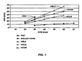
- FIG. 1 is a graph of rate-of-penetration (ROP on y-axis) versus weight-on-bit (WOB on x-axis) for earth-boring bits such as a fixed blade cutter bit, a hybrid bit of the present invention, and a three rolling-cutter bit (three roller cone bit).
- ROP on y-axis rate-of-penetration
- WOB on x-axis weight-on-bit
- the data for the bits illustrated in solid unbroken lines of the graph was generated using 121/4/ inch bits on the Hughes Christensen simulator in The Woodlands, Texas.
- the conditions were 4000 pounds (1815.6 kilograms) per square inch (2.54 cm 2 ) of bottom-hole pressure, 120 bit revolutions per minute, and 9.5 pounds (4.306 kilograms) per gallon (3.78 liters) drilling fluid or mud while drilling Carthage marble.
- the broken lines illustrate expected rate-of-penetration (ROP on y-axis) versus weight-on-bit (WOB on x-axis) for different configurations of hybrid earth-boring bits of the present inventions.
- the data used and reflected in FIG. 1 is intended to be general and to reflect general characteristics for the three types of bits, such as fixed blade cutter bits having PDC cutting elements, hybrid bits including variations thereof of the present inventions, and rolling-cutter bits (roller cone bits) whose cutting aggressiveness characteristics are illustrated.
- the solid lines on the graph show the cutting performance characteristics of three different types of earth-boring bits: a three rolling-cutter bit (three roller cones), a six blade fixed cutter bit having PDC cutting elements, and a "hybrid" bit having both (three) rolling-cutters and (three) fixed blade cutters having PDC cutting elements on the fixed blade cutters (in the "rolling- cutter leading" configuration of the present invention, as described hereinbelow).
- each type of bit has a characteristic line.
- the six fixed blade cutter bit having PDC cutting elements has the highest ROP for a given WOB resulting in a line having the steepest slope of the line showing cutting performance of the bit.
- the three rolling-cutter bit (three roller cone bit) has the lowest ROP for a given WOB resulting in a line having the shallowest slope of the line showing cutting performance of the bit.
- the hybrid bit of the present invention exhibits intermediate ROP for a given WOB resulting in a line having an intermediate slope of the line showing cutting performance of the bit between the line for the fixed blade cutter bit and the three rolling-cutter bit.
- the slope of the line (curve) plotted for ROP versus WOB for a given bit can be termed or defined as the bit's cutting aggressiveness or simply "Aggressiveness" as used herein.
- Aggressiveness Rate of Penetration ROP / Weight on Bit WOB
- One aspect of the present invention is to provide a method for the design of a hybrid earth-boring bit so that its aggressiveness characteristics can be tailored or varied to the drilling application.
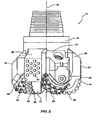
- FIGS. 2 , 3 , and 4 illustrate embodiments of hybrid earth-boring bits 11 according to the present invention.
- Hybrid bit 11 comprises a bit body 13 that is threaded or otherwise configured at its upper extent for connection into a drill string.
- Bit body 13 may be constructed of steel, or of a hard-metal (e.g., tungsten carbide) matrix material with steel inserts.
- Bit body 13 has an axial center or centerline 15 that coincides with the axis of rotation of hybrid bit 11 in most instances.
- the illustrated hybrid bit 11 is a 12-1/4 inch bit.
- FIG. 3 is used to exemplify the techniques of adjusting the aggressiveness of a hybrid bit according to the present invention, i.e., cutter leading," “blade-leading,” and “cutter-blade opposite,” as described herein.
- One of the embodiments of the hybrid bits of the present inventions illustrated in FIG. 3 is likely not a desirable production hybrid bit design when the hybrid bit is an all blade-leading design because aggressiveness of the hybrid bit is too great for certain types of formations, but not all types of formations. That is, if the hybrid bit is a hybrid bit having an all blade-leading design, it acts more as a fixed blade cutter bit. As illustrated in FIG. 1 , aggressiveness of such hybrid bit is high which might adversely affect its durability and dynamic stability.
- At least one bit leg (two of three are shown in FIG. 2 ) 17, 19, 21 depends axially downwardly from the bit body 13.
- a lubricant compensator is associated with each bit leg to compensate for pressure variations in the lubricant provided for the bearing.
- at least one fixed blade cutter (again three are shown) 23, 25, 27 depends axially downwardly from bit body 13.
- a rolling cutter 29, 31, 33 is mounted for rotation (typically on a journal bearing, but rolling-element or other bearings may be used as well) on each bit leg 17, 19, 21.
- Each rolling-cutter 29, 31, 33 has a plurality of cutting elements 35, 37, 39 arranged in generally circumferential rows thereon.
- cutting elements 35, 37, 39 are tungsten carbide inserts, each insert having an interference fit into bores or apertures formed in each rolling cutter 29, 31, 33.
- cutting elements 35, 37, 39 can be integrally formed with the cutter and hardfaced, as in the case of steel- or milled-tooth cutters.
- Materials other than tungsten carbide such as polycrystalline diamond or other super-hard or super-abrasive materials, can also be used for rolling-cutter cutting elements 35, 37, 39 on rolling-cutters 29, 31, 33.
- a plurality of cutting elements 41, 43, 45 are arranged in a row on the leading edge of each fixed blade cutter 23, 25, 27.
- Each cutting element 41, 43, 45 is a circular disc of polycrystalline diamond mounted to a stud of tungsten carbide or other hard metal, which is in turn soldered, brazed or otherwise secured to the leading edge of each fixed blade cutter.
- Thermally stable polycrystalline diamond (TSP) or other conventional fixed-blade cutting element materials may also be used.
- Each row of cutting elements 41, 43, 45 on each of the fixed blade cutters 23, 25, 27 extends from the central portion of bit body 13 to the radially outermost or gage portion or surface of bit body 13.
- a cutting element 41 on a fixed-blade cutter 23 is located at or near the central axis or centerline 15 of bit body 13 ("at or near” meaning some part of the fixed cutter is at or within about 1 mm of the centerline 15).
- the radially innermost cutting element 41 in the row on fixed blade cutter 23 has its circumference tangent to the axial center or centerline 15 of the bit body 13 and hybrid bit 11.
- a plurality of flat-topped, wear-resistant inserts 51 formed of tungsten carbide or similar hard metal with a polycrystalline diamond cutter attached thereto are provided on the radially outermost or gage surface of each fixed blade cutter 23, 25, 27. These serve to protect this portion of the bit from abrasive wear encountered at the sidewall of the borehole. Also, a row or any desired number of rows of back-up cutters 53 is provided on each fixed blade cutter 23, 25, 27 between the leading and trailing edges thereof. Back-up cutters 53 may be aligned with the main or primary cutting elements 41, 43, 45 on their respective fixed blade cutters 23, 25, 27 so that they cut in the same swath or kerf or groove as the main or primary cutting elements on a fixed blade cutter.
- back-up cutters 53 provide additional points of contact or engagement between the bit 11 and the formation being drilled, thus enhancing the stability of hybrid bit 11.
- rolling-cutters 29, 31, 33 are angularly spaced approximately 120 degrees apart from each other (measured between their axes of rotation).
- a first rolling-cutter 29 is spaced apart 58 degrees from a first fixed blade 23 (measured between the axis of rotation of rolling cutter 29 and the centerline of fixed blade 23 in a clockwise manner in FIG.
- a second rolling-cutter 31 is spaced 63 degrees from a second fixed blade 25 (measured similarly) forming a pair of cutters; and a third rolling-cutter 33 is spaced 53 degrees apart from a third fixed blade 27 (again measured the same way) forming a pair of cutters.
- FIG. 3A a cutting profile for the fixed cutting elements 41, 45, 43 on fixed blade cutters 23, 25, 27 and cutting elements 35, 37, 39 on rolling-cutters 29, 33, 31 are generally illustrated.
- an inner most cutting element 41 on fixed blade cutter 23 is tangent to the axial center 15 of the bit body 13 or hybrid bit 11.
- the innermost cutting element 43 on fixed blade cutter 27 is illustrated.
- innermost cutting element 45 on fixed blade cutter 25 is also illustrated.
- a cutting element 35 on rolling-cutter 29 is illustrated having the same cutting depth or exposure and cutting element 41 on fixed blade cutter 23 each being located at the same centerline and cutting the same swath or kerf or groove.
- Some cutting elements 41 on fixed blade cutter 23 are located in cone of the hybrid bit 11, while other cutting elements 41 are located in the nose and shoulder portion of the hybrid bit 11 having cutting elements 35 of rolling cutter 29 cutting the same swath or kerf or groove generally in the nose and shoulder of the hybrid bit 11 out to the gage thereof.
- Cutting elements 35, 37, 39 on rolling-cutters 29, 33, 31 do not extend into the cone of the hybrid bit 11 but are generally located in the nose and shoulder of the hybrid bit 11 out to the gage of the hybrid bit. Further illustrated in FIG.
- 3A are the cutting elements 37, 39 on rolling-cutters 31 and 33 and their relation to the cutting elements 43 and 45 on fixed blade cutters 27, 25 cutting the same swath or kerf or groove either being each being centered thereon or offset in the same swath or kerf or groove during a revolution of the hybrid drill bit 11. While each cutting element 41, 43, 45 and cutting element 35, 37, 39 has been illustrated having the same exposure of depth of cut so that each cutting element cuts the same amount of formation, the depth of cut may be varied in the same swath or kerf or groove, if desired.
- FIG. 3B Illustrated in FIG. 3B is a cutting profile for the fixed cutting elements 41 on fixed blade cutter 23 and cutting elements 35 on rolling-cutter 29 in relation to the each other, the fixed blade cutter 23 and the rolling-cutter 29 forming a pair of cutters on hybrid bit 11.
- some of the cutting elements 41 on fixed blade cutter 23 and cutting element 35 on rolling-cutter 29 both have the same center and cut in the same swath or kerf or groove while other cutting elements 41' on fixed blade cutter 23 and cutting element 35' on rolling cutter 29 do not have the same center but still cut in the same swath or kerf or groove.
- backup cutting elements 53 on fixed blade 23 located behind cutting elements 41 may have the same exposure of cut as cutting elements 41 or less exposure of cut as cutting elements 41 and have the same diameter or a smaller diameter than a cutting element 41.
- backup cutting elements 53 while cutting in the same swath or kerf or groove 41' as a cutting element 41 may be located off the center of a cutting element 41 located in front of a backup cutting element 53 associated therewith.
- cutting elements 41 and backup cutting elements 53 on fixed blade 23 and cutting elements 35 on rolling cutter 29 will all cut in the same swath or kerf or groove while being either centered on each other of slightly off-centered from each other having the same exposure of cut or, in the alternative, a lesser exposure of cut.
- FIG. 3C Illustrated in FIG. 3C is a cutting profile for the fixed cutting elements 43 on fixed blade cutter 27 in relation to the cutting elements 37 on rolling-cutter 33, the fixed blade cutter 27 and the rolling-cutter 33 forming a pair of cutters on hybrid bit 11.
- some of the cutting elements 43 on fixed blade cutter 27 and cutting element 37 on rolling-cutter 33 both have the same center and cutting in the same swath or kerf or groove while other cutting elements 43' on fixed blade cutter 23 and cutting element 37' on rolling cutter 33 do not have the same center but cut in the same swath or kerf or groove.
- backup cutting elements 53 on fixed blade 27 located behind cutting elements 43 may have the same exposure of cut as cutting elements 43 or less exposure of cut as cutting elements 43 and have the same diameter or a smaller diameter than a cutting element 43. Additionally, backup cutting elements 53 while cutting in the same swath or kerf or groove as a cutting element 43 may be located off the center of a cutting element 43 associated therewith.
- cutting elements 43 and backup cutting elements 53 on fixed blade cutter 27 and cutting elements 37 on rolling cutter 33 will all cut in the same swath or kerf or groove while being either centered on each other of slightly off-centered from each other having the same exposure of cut or, in the alternative, a lesser exposure of cut.
- FIG. 3D Illustrated in FIG. 3D is a cutting profile for the fixed cutting elements 45 on fixed blade cutter 25 in relation to cutting elements 39 on rolling-cutter 31 forming a pair of cutters on hybrid bit 11.
- some of the cutting elements 45 on fixed blade cutter 25 and cutting element 39 on rolling-cutter 31 both have the same center and cutting in the same swath or kerf or groove while other cutting elements 45' on fixed blade cutter 25 and cutting element 39' on rolling cutter 31 do not have the same center but cut in the same swath or kerf or groove.
- all the cutting elements 45 and 45' on fixed blade cutter 25 and cutting elements 39 and 39' on rolling cutter 33 have the same exposure to cut the same depth of formation for an equal cut of the formation, although this may be varied as desired.
- backup cutting elements 53 on fixed blade 25 located behind cutting elements 45 may have the same exposure of cut as cutting elements 45 or less exposure of cut as cutting elements 45 and have the same diameter or a smaller diameter than a cutting element 45. Additionally, backup cutting elements 53 while cutting in the same swath or kerf or groove as a cutting element 45 may be located off the center of a cutting element 45 associated therewith.
- cutting elements 45 and backup cutting elements 53 on fixed blade cutter 25 and cutting elements 39 on rolling cutter 31 will all cut in the same swath or kerf or groove while being either centered on each other of slightly off-centered from each other having the same exposure of cut or, in the alternative, a lesser exposure of cut.
- adjusting the angular spacing between rolling cutters 29, 31, 33, and fixed blade cutters 23, 25, 27 is one way in which to adjust the cutting aggressiveness or aggressiveness of a hybrid bit 11 according to the present invention.
- Spacing a rolling-cutter 29 farther away from a fixed blade cutter 23 of a pair of cutters on the hybrid bit 11 allows or causes the cutting elements of the fixed blade cutter 23 to dominate the cutting action of the pair of cutters thereby increasing the cutting aggressiveness or aggressiveness of the hybrid bit 11.
- Another way of altering the cutting aggressiveness of a hybrid bit 11 is by having a rolling cutter to lead a trailing fixed blade cutter of a pair of cutters (including one of each type of cutter) or to have a fixed blade cutter lead a trailing rolling cutter of a pair of cutters (including one of each type of cutter).
- a rolling cutter leads a rolling.cutter of a pair of cutters of a hybrid bit 11 (see line HBLC)
- the hybrid bit 11 has more cutting aggressiveness cutting more like a fixed blade cutter polycrystalline diamond (PDC) bit.
- PDC polycrystalline diamond
- FIG. 1 when a rolling cutter leads a fixed blade cutter of a pair of cutters of a hybrid bit 11 (see line HCLB), the aggressiveness decreases with the hybrid bit having aggressiveness more like a rolling-cutter (roller cone) bit.
- one rolling cutter 29 "leads” its trailing fixed blade cutter 23 as a pair of cutters.
- one fixed blade cutter 25 "leads” its trailing rolling cutter 33 as a pair of cutters.
- leads it is meant that the cutting elements on the adjacent, trailing structure (whether fixed blade cutter or rolling cutter) are arranged to fall in the same swath or kerf or groove as that made by the cutting elements on the leading structure (whether a fixed blade cutter or rolling cutter), as indicated by phantom lines in FIG. 3E or FIG.3F .
- the cutting elements 41 on fixed blade cutter 23 fall in the same swath or kerf or groove (see FIG. 3A , FIG. 3B ) as the cutting elements 35 on rolling cutter 29.
- the cutting elements 37 on rolling-cutter 33 fall in the same swath or kerf or groove (see FIG. 3A , FIG. 3C ) as cutting elements 45 on fixed blade cutter 25.
- rolling cutter 31 has its cutting elements 39 arranged to lead the cutting elements 43 on the opposing (if not directly opposite, i.e., 180 degrees) fixed blade cutter 27.
- fixed blade cutter 27 and rolling-cutter 31 bear load approximately equally on the hybrid bit 11.
- each fixed blade cutter should be "paired" with a rolling-cutter such that the cutting elements on the paired fixed blade cutter and rolling-cutter fall in the same swath or kerf or groove when drilling a formation.
- All rolling cutters can lead all fixed blade cutters, making a less aggressive bit (see solid line HCLB in FIG. 1 ); or all fixed blade cutters can lead all rolling-cutters, making a more aggressive bit (see broken line HBLC in FIG. 1 ), or the all cutting elements of a rolling-cutter can fall in the same swath or kerf or groove as the cutting elements on an opposing fixed blade (see broken line HCOB in FIG.1 ), or any combination thereof on a hybrid bit of the present invention.
- FIG. 4 illustrates an embodiment of the earth-boring hybrid bit 111 according to the present invention that is similar to the embodiments of FIG. 3 in all respects, except that cutting elements 135, 137, 139 on each of the rolling cutters-129, 133, 131 respectively are arranged to cut in the same swath or kerf or groove as the cutting elements 145, 141, 143 on the opposite or opposing fixed blade cutters 125, 122, 127 respectively.
- the cutting elements 135 on rolling cutter 129 fall in the same swath or kerf or groove as the cutting elements 145 on the opposing fixed blade cutter 125.
- the hybrid bit 111 of FIG. 4 having the "cutter-opposite" configuration of pairs of cutters, appears to be extremely stable in comparison to all configurations of "cutter-leading" pairs of cutters or all “blade-leading” pairs of cutters. Additionally, based on preliminary testing, the hybrid bit 111 of FIG. 4 out drills a conventional rolling-cutter bit and a conventional fixed blade cutter bit having polycrystalline diamond cutting elements (PDC bit), as well as other hybrid bit configurations ("cutter-leading") in hard sandstone.
- PDC bit polycrystalline diamond cutting elements
- a conventional 12-1/4 inch rolling-cutter bit drills the hard sandstone at 11 feet/hour (3.35 meters/hour), a conventional fixed blade cutter bit having polycrystalline diamond cutting elements (PDC bit) at 13 feet/hour (3.96 meters/hour), the hybrid bit with "cutter-leading" pair of cutters configuration at 14 feet/hour (4.26 meters/hour) and the hybrid bit with "cutter-opposite" pair of cutters configuration at 21 feet/hour (6.40 meters/hour).
- PDC bit polycrystalline diamond cutting elements
- Some different types of hard sandstone is the material that is most difficult to drill using fixed blade cutter bits having polycrystalline diamond cutting elements (PDC bits) due to a level of scatter vibrations.
- the balanced loading resulting from the "cutter-opposite" pair of cutters configuration of a hybrid bit is believed to produce the dramatic difference over other types and configurations of bits.
- softer formations soft and medium-hard
- the aggressiveness of a hybrid bit can be tailored or varied to the particular drilling and formation conditions encountered.
- Still another way to adjust or vary the aggressiveness of the hybrid bit 11 is to arrange the cutting elements 35, 37, 39 on the rolling-cutters 29, 31, 33 so that they project deeper into the formation being drilled than the cutting elements 41, 43, 45 on the fixed blade cutters 23, 25, 27.
- the simplest (and least effective) way to do this is to adjust the projection of some or all of the cutting elements 35, 37, 39 on the rolling-cutters 29, 31, 33 from the surface of each rolling cutter 29, 31, 33 so that they project in the axial direction (parallel to the bit axis 15) further than some or all of the cutting elements 41, 43, 45 on fixed blades cutters 23, 25, 27.
- the extra axial projection of a cutting element of the cutting elements on the rolling cutters causes the cutting element to bear more load than an associated cutting clement on a fixed blade cutter and protects an associated cutting element of the fixed blade cutter.
- each cutting element of a rolling-cutter is a combination of the projection of each cutting element of a rolling-cutter from the surface of its rolling cutter, combined with its angular spacing (pitch) from adjacent cutting elements that governs whether the cutting elements of a rolling-cutter actually bear more of the cutting load than an associated cutting element on a fixed blade cutter.
- This combination is referred to herein as "effective projection,” and is illustrated in FIGS. 5 and 6 .
- the effective projection A of a given cutting element of a rolling-cutter, or that projection of the cutting element available to penetrate into earthen formation is limited by the projection of each adjacent cutting element and the angular distance or pitch C between the adjacent cutting elements and the given cutting element.
- FIG. 6 illustrates "full" effective projection B in that the pitch is selected so that the adjacent cutting elements on either side of a given cutting element permit penetration of the cutting element to a depth equal to its full projection from the surface of a rolling-cutter.
- a method for designing a hybrid earth-boring bit of the present invention permits or allows the cutting aggressiveness of a hybrid bit to be adjusted or selected based on the relationship of at least a pair of cutters comprising a fixed blade cutter and a rolling-cutter, of a plurality of fixed blade cutters and rolling-cutters, wherein the relationship includes a fixed blade cutter leading a rolling-cutter in a pair of cutters, a rolling-cutter leading a fixed blade cutter in a pair of cutters, a rolling-cutter being located opposite a fixed blade cutter in a pair of cutters on the bit, and the angular relationship of a fixed blade cutter and a rolling-cutter of a pair of cutter regarding the amount of leading or trailing of the cutter from an associated cutter of the pair of cutters.
- the cutting aggressiveness of a hybrid bit of the present invention being achieved by defining a cutting aggressiveness of a hybrid drill bit and the various combinations of pair of a fixed blade cutter and a rolling-cutter, when compared to each other and to different types of drill bits, such as a rolling-cutter drill bit and a fixed blade cutter drill bit, either as the ratio of torque to weight-on-bit or as the ratio of penetration rate to weight-on-bit.
- the cutting aggressiveness for a hybrid bit of the present invention being adjusted by performing at least one of the following steps:
Landscapes
- Engineering & Computer Science (AREA)
- Life Sciences & Earth Sciences (AREA)
- Geology (AREA)
- Mining & Mineral Resources (AREA)
- Mechanical Engineering (AREA)
- Physics & Mathematics (AREA)
- Environmental & Geological Engineering (AREA)
- Fluid Mechanics (AREA)
- General Life Sciences & Earth Sciences (AREA)
- Geochemistry & Mineralogy (AREA)
- Earth Drilling (AREA)
- Drilling Tools (AREA)
Description
- The present invention relates in general to earth-boring bits and, in particular, to an improved bit having a combination of rolling-cutters and fixed cutters and cutting elements and a method of design and operation of such bits.
- The success of rotary drilling enabled the discovery of deep oil and gas reservoirs and production of enormous quantities of oil. The rotary rock bit was an important invention that made the success of rotary drilling possible. Only soft earthen formations could be penetrated commercially with the earlier drag bit and cable tool, but the two-cone rock bit, invented by
Howard R. Hughes, U.S. Patent No. 930,759 , drilled the caprock at the Spindletop field near Beaumont, Texas, with relative ease. That venerable invention, within the first decade of the last century, could drill a scant fraction of the depth and speed of the modem rotary rock bit. The original Hughes bit drilled for hours; the modem bit now drills for days. Modem bits sometimes drill for thousands of feet (hundreds of meters) instead of merely a few feet/meters. Many advances have contributed to the impressive improvements in rotary rock bits. - In drilling boreholes in earthen formations using rolling-cone or rolling-cutter bits, rock bits having one, two, or three rolling cutters rotatably mounted thereon are employed. The bit is secured to the lower end of a drill string that is rotated from the surface or by downhole motors or turbines. The cutters mounted on the bit roll and slide upon the bottom of the borehole as the drill string is rotated, thereby engaging and disintegrating the formation material to be removed. The rolling-cutters are provided with cutting elements or teeth that are forced to penetrate and gouge the bottom of the borehole by weight from the drill string. The cuttings from the bottom and sides of the borehole are washed away and disposed by drilling fluid that is pumped down from the surface through the hollow, rotating drill string, and the nozzles as orifices on the drill bit. Eventually the cuttings are carried in suspension in the drilling fluid to the surface up the exterior of the drill string.
- Rolling-cutter bits dominated petroleum drilling for the greater part of the 20th century. With improvements in synthetic diamond technology that occurred in the 1970s and 1980s, the fixed blade cutter bit or drag bit became popular again in the latter part of the 20th century. Modern fixed blade cutter bits are often referred to as "diamond" or "PDC" (polycrystalline diamond cutter bits) bits and are far removed from the original fixed bladecutter bits of the 19th and early 20th centuries. Diamond or PDC bits carry cutting elements comprising polycrystalline diamond compact layers or "tables" formed on and bonded to a supporting substrate, conventionally of cemented tungsten carbide, the cutting element being arranged in selected location on blades or other structures on the bit body with the diamond tables facing generally in the direction of bit rotation. Fixed blade cutter bits have the advantage of being much more aggressive during drilling and therefore drill much faster at equivalent weight-on-bit levels (WOB) than, for instance, a rolling-cutter bit. In addition, they have no moving parts, which make their design less complex and more robust. The drilling mechanics and dynamics of fixed blade cutter bits are different from those of rolling-cutter bits precisely because they are more aggressive in cutting and require more torque to rotate during drilling. During a drilling operation, fixed blade cutter bits are used in a manner similar to that for rolling-cutter bits, the fixed blade cutter bits also being rotated against a formation being drilled under applied weight-on-bit to remove formation material. The cutting elements on the fixed blade cutters are continuously engaged as they scrape material from the formation, while in a rolling-cutter bit the cutting elements on each rolling cutter indent the formation intermittently with little or no relative motion (scraping) between the cutting element and the formation. A rolling-cutter bit and a fixed blade cutter bit each have particular applications for which they are more suitable than the other. The much more aggressive fixed blade cutter bit is superior in drilling in a softer formation to a medium hard formation while the rolling-cutter bit excels in drilling hard formations, abrasive formations, or any combination thereof.
- In the prior art, some earth-boring bits use a combination of one or more rolling cutters and one or more fixed blade cutters. Some of these combination-type drill bits are referred to as hybrid bits. Previous designs of hybrid bits, such as
U.S. Patent 4,343,371, to Baker, III , have used rolling-cutters to do most of the formation cutting, especially in the center of the hole or bit. Another type of hybrid bit is described inU.S. Patent 4,444,281, to Schumacher , has equal numbers of fixed blade cutters and rolling-cutters in essentially symmetrical arrangements. In such bits, the rolling-cutters do most of the cutting of the formation while the fixed blade cutters act as scrapers to remove uncut formation indentations left by the rolling-cutters as well as cuttings left behind by the rolling-cutters. While such a hybrid bit improves the cutting efficiency of the hybrid bit over that of a rolling-cutter bit in softer formations, it has only a small or marginal effect on improving the overall performance in harder formations. When comparing a fixed blade cutter bit to a rolling-cutter bit, the high cutting aggressiveness of a fixed blade cutter bit frequently causes such bit to reach the torque capacity or limit of a conventional rotary table drilling systems or motors, even at a moderate level of weight-on-bit during drilling, particularly on larger diameter drill bits. The reduced cutting aggressiveness of a rolling-cutter bit, on the other hand, frequently causes the rolling-cutter bit to exceed the weight-on-bit limits of the drill string before reaching the full torque capacity of a conventional rotary table drive drilling system. -
GB 2 183 694 A -
US 2005/087370 A1 discloses a method for varying cutting aggressiveness of a hybrid bit having a bit body and three rolling cutters mounted for rotation on a bit leg depending downwardly from the body. A plurality of cutting elements is arranged on each rolling cutter. The aggressiveness of the bit is defined as a function of penetration rate of the bit during drilling. The aggressiveness is adjusted by adjusting the effective projection between at least two adjacent cutting elements on a rolling cutter. - The object of the invention is to provide a method for varying cutting aggressiveness of a hybrid drill bit and a corresponding hybrid drill bit having a high aggressiveness.
-
US 4 343 371 A discloses a hybrid rock bit having a pair of opposing roller cones with cutting elements extending from and disposed on the surface. The bit further consists of a pair of opposing drag bit leg segments on opposite sides of the cutter cones having a plurality of strategically positioned diamond cutting elements extending from and mounted to the surface of the drag bit leg. As the cones roll on the borehole bottom, inner inserts in rows "A," "B," "C," and "D" of each of the opposed cones cut deep, relatively narrow kerfs in the borehole bottom. The ridges that remain adjacent to the kerfs are subsequently removed by the drag bit leg segments. - This object is achieved by a method comprising the features of claim 1. Preferred ways to carry out the method of the invention are claimed in claims 2 to 7.
- The above object is further achieved by a hybrid drill bit comprising the features of
claim 8. Preferred embodiments of the hybrid drill bit of the invention are claimed in claims 9 to 12. - A hybrid earth-boring bit comprising a bit body having a central axis, at least one, preferably three fixed blade cutters, depending downwardly from the bit body, each fixed blade cutter having a leading edge, and at least one rolling-cutter, preferably three rolling-cutters, mounted for rotation on the bit body. A fixed blade cutter and a rolling-cutter forming a pair of cutters on the hybrid bit body. When there are three rolling-cutters, each rolling-cutter is located between two fixed blade cutters.
- A plurality of cutting elements is arranged on the leading edge of each fixed blade cutter and a plurality of cutting elements is arranged on each of the rolling-cutters. The rolling-cutters each have cutting elements arranged to engage formation in the same swath or kerf or groove as a matching cutting element on a fixed blade cutter. In the pair of cutters, the matching fixed blade cutter being arranged to be either trailing, leading, or opposite the rolling- cutter to adapt the hybrid bit to the application by modifying the cutting aggressiveness thereof to get the best balance between the rate-of penetration of the bit and the durability of the bit for the pair of cutters.
- A method for designing a hybrid earth-boring bit of the present invention permits or allows the cutting aggressiveness of a hybrid bit to be adjusted or selected based on the relationship of at least a pair of cutters comprising a fixed blade cutter and a rolling-cutter, of a plurality of fixed blade cutters and rolling-cutters, wherein the relationship includes a fixed blade cutter leading a rolling-cutter in a pair of cutters, a rolling cutter leading a fixed blade cutter in a pair of cutters, a rolling-cutter being located opposite a fixed blade cutter in a pair of cutters on the bit, and the angular relationship of a fixed blade cutter and a rolling-cutter of a pair of cutter regarding the amount of leading or trailing of the cutter from an associated cutter of the pair of cutters. The cutting aggressiveness of a hybrid bit of the present invention being achieved by defining a cutting aggressiveness of a hybrid drill bit and the various combinations of pair of a fixed blade cutter and a rolling-cutter, when compared to each other and to different types of drill bits, such as a rolling-cutter drill bit and a fixed blade cutter drill bit, either as the ratio of torque to weight-on-bit or as the ratio of penetration rate to weight-on-bit. The cutting aggressiveness for a hybrid bit of the present invention being adjusted by performing at least one of the following steps:
- adjusting the angular distance between each rolling-cutter and each fixed blade cutter of a pair of cutters of the bit;
- adjusting the effective projection of the cutting elements on a rolling cutter;
- arranging the cutting elements of a fixed blade cutter and the cutting elements of a rolling-cutter so that at least one cutting element of a rolling-cutter and at least one cutting element of a fixed blade cutter cut the same swath or kerf or groove during a drilling operation; and
- arranging a pair of at least one cutting element of a fixed blade cutter and cutting element of a rolling-cutter so that the rolling cutter either leads the fixed blade cutter ((<180°) angular distance], the rolling-cutter opposes the fixed blade cutter [(=180°) angular distance], or trails the fixed blade cutter [(>180°) angular distance].
- Other features and advantages of the present invention become apparent with reference to the drawings and detailed description of the invention.
-
-
FIG. 1 is a graph illustrating the relative aggressiveness of a rolling-cutter bit, a fixed blade cutter bit having polycrystalline diamond cutters or PDC bit, and embodiments of hybrid bits of the present inventions. -
FIG. 2 is an elevation view of a hybrid earth-boring bit illustrative of the present invention. -
FIG. 3 is a bottom plan form view of the hybrid earth-boring bit ofFIG. 2 . -
FIG. 3A is a view of cutting elements of a three fixed blade cutters and cutting elements of three rolling-cutters of embodiments of a hybrid bit of the present inventions ofFIGS. 1 through 3 . -
FIG. 3B is a view of cutting elements of a first fixed blade cutter and cutting elements of a first rolling-cutter of an embodiment of a hybrid bit of the present invention; -
FIG. 3C is a view of cutting elements of a second fixed blade cutter and cutting elements of a second rolling-cutter of an embodiment of a hybrid bit of the present invention; -
FIG. 3D is a view of cutting elements of a third fixed blade cutter and cutting elements of a third rolling-cutter of an embodiment of a hybrid bit of the present invention; -
FIG. 3E is a view ofFIG. 3 showing a rolling-cutter and a fixed blade cutter of a hybrid bit ofFIG. 3 of the present invention. -
FIG. 3F is a view ofFIG. 3 showing another fixed blade cutter and another rolling-cutter of a hybrid bit ofFIG. 3 of the present invention. -
FIG. 4 is a bottom plan form view of another embodiment of a hybrid earth-boring bit of the present invention. -
FIGS. 5 and6 are partial schematic views of rolling-cutters and cutting elements of rolling-cutters interfacing with the formation being drilled. - Turning now to the drawing figures, and particularly to
FIG. 1 , the characteristics of various embodiments of the present invention are described.FIG. 1 is a graph of rate-of-penetration (ROP on y-axis) versus weight-on-bit (WOB on x-axis) for earth-boring bits such as a fixed blade cutter bit, a hybrid bit of the present invention, and a three rolling-cutter bit (three roller cone bit). The data for the bits illustrated in solid unbroken lines of the graph was generated using 121/4/ inch bits on the Hughes Christensen simulator in The Woodlands, Texas. The conditions were 4000 pounds (1815.6 kilograms) per square inch (2.54 cm2) of bottom-hole pressure, 120 bit revolutions per minute, and 9.5 pounds (4.306 kilograms) per gallon (3.78 liters) drilling fluid or mud while drilling Carthage marble. The broken lines illustrate expected rate-of-penetration (ROP on y-axis) versus weight-on-bit (WOB on x-axis) for different configurations of hybrid earth-boring bits of the present inventions. The data used and reflected inFIG. 1 is intended to be general and to reflect general characteristics for the three types of bits, such as fixed blade cutter bits having PDC cutting elements, hybrid bits including variations thereof of the present inventions, and rolling-cutter bits (roller cone bits) whose cutting aggressiveness characteristics are illustrated. - The solid lines on the graph show the cutting performance characteristics of three different types of earth-boring bits: a three rolling-cutter bit (three roller cones), a six blade fixed cutter bit having PDC cutting elements, and a "hybrid" bit having both (three) rolling-cutters and (three) fixed blade cutters having PDC cutting elements on the fixed blade cutters (in the "rolling- cutter leading" configuration of the present invention, as described hereinbelow). As shown, each type of bit has a characteristic line. The six fixed blade cutter bit having PDC cutting elements has the highest ROP for a given WOB resulting in a line having the steepest slope of the line showing cutting performance of the bit. The three rolling-cutter bit (three roller cone bit) has the lowest ROP for a given WOB resulting in a line having the shallowest slope of the line showing cutting performance of the bit. The hybrid bit of the present invention exhibits intermediate ROP for a given WOB resulting in a line having an intermediate slope of the line showing cutting performance of the bit between the line for the fixed blade cutter bit and the three rolling-cutter bit.
- The slope of the line (curve) plotted for ROP versus WOB for a given bit can be termed or defined as the bit's cutting aggressiveness or simply "Aggressiveness" as used herein. "Aggressiveness," for purposes of this application and the inventions described herein, is defined as follows:

Thus aggressiveness, as the mathematical slope of a line, has a value greater than zero. Measured purely in terms of aggressiveness, it would seem that fixed blade cutter bits would be selected in all instances for drilling. However, other factors come into play. For example, there are limits on the amount of WOB and torque to turn the bit that can be applied, generally based on either the drilling application or the capacity of the drill string and drilling rig. Similarly, as WOB and ROP increase, the drill string torque requirements for a bit increase rapidly, especially with fixed blade cutter bits, and cause harmful vibrations. Rolling-cutter bits, on the other hand, require high WOB which, in the extreme, may buckle a bottom hole assembly or exceed the load bearing capacity of the cutter bearings of the rolling-cutters of the rolling-cutter bit. Accordingly, different types of bits, whether a fixed blade cutter bit, a rolling-cutter bit, or a hybrid bit, have different advantages in different situations. One aspect of the present invention is to provide a method for the design of a hybrid earth-boring bit so that its aggressiveness characteristics can be tailored or varied to the drilling application. -
FIGS. 2 ,3 , and4 illustrate embodiments of hybrid earth-boringbits 11 according to the present invention.Hybrid bit 11 comprises abit body 13 that is threaded or otherwise configured at its upper extent for connection into a drill string.Bit body 13 may be constructed of steel, or of a hard-metal (e.g., tungsten carbide) matrix material with steel inserts.Bit body 13 has an axial center orcenterline 15 that coincides with the axis of rotation ofhybrid bit 11 in most instances. The illustratedhybrid bit 11 is a 12-1/4 inch bit. Thehybrid bit 11 shown inFIG. 3 is used to exemplify the techniques of adjusting the aggressiveness of a hybrid bit according to the present invention, i.e., cutter leading," "blade-leading," and "cutter-blade opposite," as described herein. One of the embodiments of the hybrid bits of the present inventions illustrated inFIG. 3 , is likely not a desirable production hybrid bit design when the hybrid bit is an all blade-leading design because aggressiveness of the hybrid bit is too great for certain types of formations, but not all types of formations. That is, if the hybrid bit is a hybrid bit having an all blade-leading design, it acts more as a fixed blade cutter bit. As illustrated inFIG. 1 , aggressiveness of such hybrid bit is high which might adversely affect its durability and dynamic stability. - Illustrated in
FIG. 2 andFIG. 3 , at least one bit leg (two of three are shown inFIG. 2 ) 17, 19, 21 depends axially downwardly from thebit body 13. In the illustrated embodiment, a lubricant compensator is associated with each bit leg to compensate for pressure variations in the lubricant provided for the bearing. In between eachbit leg bit body 13. - A rolling
cutter bit leg cutter elements elements cutter elements cutter cutting elements cutters - A plurality of cutting
elements blade cutter element elements blade cutters bit body 13 to the radially outermost or gage portion or surface ofbit body 13. On at least one of the rows on one of the fixedblade cutters element 41 on a fixed-blade cutter 23 is located at or near the central axis orcenterline 15 of bit body 13 ("at or near" meaning some part of the fixed cutter is at or within about 1 mm of the centerline 15). In the illustrated embodiment, the radially innermost cuttingelement 41 in the row on fixedblade cutter 23 has its circumference tangent to the axial center orcenterline 15 of thebit body 13 andhybrid bit 11. - A plurality of flat-topped, wear-
resistant inserts 51 formed of tungsten carbide or similar hard metal with a polycrystalline diamond cutter attached thereto are provided on the radially outermost or gage surface of each fixedblade cutter cutters 53 is provided on each fixedblade cutter cutters 53 may be aligned with the main orprimary cutting elements blade cutters cutters 53 provide additional points of contact or engagement between thebit 11 and the formation being drilled, thus enhancing the stability ofhybrid bit 11. - In the embodiments of the inventions illustrated in
FIG. 3 , rolling-cutters cutter axial center 15 ofbit body 13 orhybrid bit 11, although each or all of the rolling-cutters bit body 13 orhybrid bit 11. As illustrated, a first rolling-cutter 29 is spaced apart 58 degrees from a first fixed blade 23 (measured between the axis of rotation of rollingcutter 29 and the centerline of fixedblade 23 in a clockwise manner inFIG. 3 ) forming a pair of cutters. A second rolling-cutter 31 is spaced 63 degrees from a second fixed blade 25 (measured similarly) forming a pair of cutters; and a third rolling-cutter 33 is spaced 53 degrees apart from a third fixed blade 27 (again measured the same way) forming a pair of cutters. - In
FIG. 3A , a cutting profile for the fixedcutting elements blade cutters elements cutters cutting element 41 on fixedblade cutter 23 is tangent to theaxial center 15 of thebit body 13 orhybrid bit 11. Theinnermost cutting element 43 on fixedblade cutter 27 is illustrated. Also, innermost cuttingelement 45 on fixedblade cutter 25 is also illustrated. A cuttingelement 35 on rolling-cutter 29 is illustrated having the same cutting depth or exposure and cuttingelement 41 on fixedblade cutter 23 each being located at the same centerline and cutting the same swath or kerf or groove. Some cuttingelements 41 on fixedblade cutter 23 are located in cone of thehybrid bit 11, while other cuttingelements 41 are located in the nose and shoulder portion of thehybrid bit 11 havingcutting elements 35 of rollingcutter 29 cutting the same swath or kerf or groove generally in the nose and shoulder of thehybrid bit 11 out to the gage thereof.Cutting elements cutters hybrid bit 11 but are generally located in the nose and shoulder of thehybrid bit 11 out to the gage of the hybrid bit. Further illustrated inFIG. 3A are the cuttingelements cutters elements blade cutters hybrid drill bit 11. While each cuttingelement element - Illustrated in
FIG. 3B is a cutting profile for the fixedcutting elements 41 on fixedblade cutter 23 and cuttingelements 35 on rolling-cutter 29 in relation to the each other, the fixedblade cutter 23 and the rolling-cutter 29 forming a pair of cutters onhybrid bit 11. As illustrated, some of the cuttingelements 41 on fixedblade cutter 23 and cuttingelement 35 on rolling-cutter 29 both have the same center and cut in the same swath or kerf or groove while other cutting elements 41' on fixedblade cutter 23 and cutting element 35' on rollingcutter 29 do not have the same center but still cut in the same swath or kerf or groove. As illustrated, all thecutting elements 41 and 41' on fixedblade cutter 23 and cuttingelements 35 and 35' on rollingcutter 29 have the same exposure to cut the same depth of formation for an equal cut of the formation during a revolution of thehybrid drill bit 11, although this may be varied as desired. Further illustrated inFIG. 3B in broken lines,backup cutting elements 53 on fixedblade 23 located behind cuttingelements 41 may have the same exposure of cut as cuttingelements 41 or less exposure of cut as cuttingelements 41 and have the same diameter or a smaller diameter than a cuttingelement 41. Additionally,backup cutting elements 53 while cutting in the same swath or kerf or groove 41' as a cuttingelement 41 may be located off the center of a cuttingelement 41 located in front of abackup cutting element 53 associated therewith. In this manner, cuttingelements 41 andbackup cutting elements 53 on fixedblade 23 and cuttingelements 35 on rollingcutter 29 will all cut in the same swath or kerf or groove while being either centered on each other of slightly off-centered from each other having the same exposure of cut or, in the alternative, a lesser exposure of cut. - Illustrated in
FIG. 3C is a cutting profile for the fixedcutting elements 43 on fixedblade cutter 27 in relation to the cuttingelements 37 on rolling-cutter 33, the fixedblade cutter 27 and the rolling-cutter 33 forming a pair of cutters onhybrid bit 11. As illustrated, some of the cuttingelements 43 on fixedblade cutter 27 and cuttingelement 37 on rolling-cutter 33 both have the same center and cutting in the same swath or kerf or groove while other cutting elements 43' on fixedblade cutter 23 and cutting element 37' on rollingcutter 33 do not have the same center but cut in the same swath or kerf or groove. As illustrated, all thecutting elements 43 and 43' on fixedblade cutter 27 and cuttingelements 37 and 37' on rollingcutter 33 have the same exposure to cut the same depth of formation for an equal cut of the formation during a revolution of thehybrid drill bit 11, although this may be varied as desired. Further illustrated inFIG. 3C in broken lines,backup cutting elements 53 on fixedblade 27 located behind cuttingelements 43 may have the same exposure of cut as cuttingelements 43 or less exposure of cut as cuttingelements 43 and have the same diameter or a smaller diameter than a cuttingelement 43. Additionally,backup cutting elements 53 while cutting in the same swath or kerf or groove as a cuttingelement 43 may be located off the center of a cuttingelement 43 associated therewith. In this manner, cuttingelements 43 andbackup cutting elements 53 on fixedblade cutter 27 and cuttingelements 37 on rollingcutter 33 will all cut in the same swath or kerf or groove while being either centered on each other of slightly off-centered from each other having the same exposure of cut or, in the alternative, a lesser exposure of cut. - Illustrated in
FIG. 3D is a cutting profile for the fixedcutting elements 45 on fixedblade cutter 25 in relation to cuttingelements 39 on rolling-cutter 31 forming a pair of cutters onhybrid bit 11. As illustrated, some of the cuttingelements 45 on fixedblade cutter 25 and cuttingelement 39 on rolling-cutter 31 both have the same center and cutting in the same swath or kerf or groove while other cutting elements 45' on fixedblade cutter 25 and cutting element 39' on rollingcutter 31 do not have the same center but cut in the same swath or kerf or groove. As illustrated, all thecutting elements 45 and 45' on fixedblade cutter 25 and cuttingelements 39 and 39' on rollingcutter 33 have the same exposure to cut the same depth of formation for an equal cut of the formation, although this may be varied as desired. As illustrated, all thecutting elements 45 and 45' on fixedblade cutter 25 and cuttingelements 39 and 39' on rolling-cutter 31 have the same exposure to cut the same depth of formation for an equal cut of the formation during a revolution of thehybrid drill bit 11. Further illustrated inFIG. 3D in broken lines,backup cutting elements 53 on fixedblade 25 located behind cuttingelements 45 may have the same exposure of cut as cuttingelements 45 or less exposure of cut as cuttingelements 45 and have the same diameter or a smaller diameter than a cuttingelement 45. Additionally,backup cutting elements 53 while cutting in the same swath or kerf or groove as a cuttingelement 45 may be located off the center of a cuttingelement 45 associated therewith. In this manner, cuttingelements 45 andbackup cutting elements 53 on fixedblade cutter 25 and cuttingelements 39 on rollingcutter 31 will all cut in the same swath or kerf or groove while being either centered on each other of slightly off-centered from each other having the same exposure of cut or, in the alternative, a lesser exposure of cut. - When considering a pair of cutters of the
hybrid bit 11 including a rolling cutter and a fixed blade cutter, each having cutting elements thereon, having the same exposure of cut, and located at the same radial location from the axial center of thehybrid bit 11 cutting the same swath or kerf or groove, adjusting the angular spacing between rollingcutters blade cutters hybrid bit 11 according to the present invention. When considering a pair of cutters having cutting elements thereon having the same exposure of cut and located at the same radial location from the axial center of thehybrid bit 11 cutting the same swath or kerf or groove on thehybrid bit 11, the closer a rollingcutter 29 is to a fixedblade cutter 23 of the pair of cutters of thehybrid bit 11, the rolling-cutter 29 is the primary cutter of the pair with the fixedblade cutter 23 cutting less of the pair. Spacing arolling cutter 29 closer to a fixedblade cutter 23 of a pair of cutters on thehybrid bit 11 causes the rollingcutter 29 to have a more dominate cutting action of the pair of cutters thereby causing thehybrid bit 11 to have a less cutting aggressiveness of aggressiveness. Spacing a rolling-cutter 29 farther away from a fixedblade cutter 23 of a pair of cutters on thehybrid bit 11 allows or causes the cutting elements of the fixedblade cutter 23 to dominate the cutting action of the pair of cutters thereby increasing the cutting aggressiveness or aggressiveness of thehybrid bit 11. - Another way of altering the cutting aggressiveness of a
hybrid bit 11 is by having a rolling cutter to lead a trailing fixed blade cutter of a pair of cutters (including one of each type of cutter) or to have a fixed blade cutter lead a trailing rolling cutter of a pair of cutters (including one of each type of cutter). As illustrated in drawingFIG. 1 , when a fixed blade cutter leads a rolling.cutter of a pair of cutters of a hybrid bit 11 (see line HBLC), thehybrid bit 11 has more cutting aggressiveness cutting more like a fixed blade cutter polycrystalline diamond (PDC) bit. As illustrated inFIG. 1 , when a rolling cutter leads a fixed blade cutter of a pair of cutters of a hybrid bit 11 (see line HCLB), the aggressiveness decreases with the hybrid bit having aggressiveness more like a rolling-cutter (roller cone) bit. - In the illustrated
hybrid bit 11 ofFIG. 3E , for the purposes of illustrating different embodiments of the present invention, one rollingcutter 29 "leads" its trailing fixedblade cutter 23 as a pair of cutters. As illustrated inFIG. 3F as another embodiment of the present invention, one fixedblade cutter 25 "leads" its trailingrolling cutter 33 as a pair of cutters. By "leads" it is meant that the cutting elements on the adjacent, trailing structure (whether fixed blade cutter or rolling cutter) are arranged to fall in the same swath or kerf or groove as that made by the cutting elements on the leading structure (whether a fixed blade cutter or rolling cutter), as indicated by phantom lines inFIG. 3E orFIG.3F . Thus, the cuttingelements 41 on fixedblade cutter 23 fall in the same swath or kerf or groove (seeFIG. 3A ,FIG. 3B ) as the cuttingelements 35 on rollingcutter 29. Similarly, the cuttingelements 37 on rolling-cutter 33 fall in the same swath or kerf or groove (seeFIG. 3A ,FIG. 3C ) as cuttingelements 45 on fixedblade cutter 25. when a rolling cutter leads a trailing fixed blade cutter, cutting aggressiveness or aggressiveness of thehybrid bit 11 is decreased. Conversely, when a fixed blade cutter leads a trailing rolling-cutter, cutting aggressiveness or aggressiveness of thehybrid bit 11 is increased. Such is illustrated inFIG. 1 in the broken lines labeled HCLB and HBLC therein. - Also, in the embodiments of
FIG. 3 , rollingcutter 31 has itscutting elements 39 arranged to lead the cuttingelements 43 on the opposing (if not directly opposite, i.e., 180 degrees) fixedblade cutter 27. Thus, being angularly spaced-apart approximately 180 degrees on thehybrid bit 11, fixedblade cutter 27 and rolling-cutter 31 bear load approximately equally on thehybrid bit 11. In most cases, where there are an equal number of fixed blade cutters and rolling-cutters, each fixed blade cutter should be "paired" with a rolling-cutter such that the cutting elements on the paired fixed blade cutter and rolling-cutter fall in the same swath or kerf or groove when drilling a formation. All rolling cutters can lead all fixed blade cutters, making a less aggressive bit (see solid line HCLB inFIG. 1 ); or all fixed blade cutters can lead all rolling-cutters, making a more aggressive bit (see broken line HBLC inFIG. 1 ), or the all cutting elements of a rolling-cutter can fall in the same swath or kerf or groove as the cutting elements on an opposing fixed blade (see broken line HCOB inFIG.1 ), or any combination thereof on a hybrid bit of the present invention. -
FIG. 4 illustrates an embodiment of the earth-boringhybrid bit 111 according to the present invention that is similar to the embodiments ofFIG. 3 in all respects, except that cuttingelements elements blade cutters elements 135 on rollingcutter 129 fall in the same swath or kerf or groove as the cuttingelements 145 on the opposing fixedblade cutter 125. The same is true for the cuttingelements 139 on rollingcutter 131 and the cuttingelements 143 on the opposing fixedblade cutter 127; and the cuttingelements 137 on rollingcutter 133 and the cuttingelements 141 on opposing fixedblade cutter 123. This can be called a "cutter-opposite" arrangement of cutting elements. In such an arrangement, rather than the cutting elements on a fixed blade cutter or rolling-cutter "leading" the cutting elements on a trailing rolling-cutter or fixed blade cutter, the cutting elements on a fixed blade cutter or rolling-cutter "oppose" those on the opposing or opposite rolling-cutter or fixed blade cutter. - The
hybrid bit 111 ofFIG. 4 , having the "cutter-opposite" configuration of pairs of cutters, appears to be extremely stable in comparison to all configurations of "cutter-leading" pairs of cutters or all "blade-leading" pairs of cutters. Additionally, based on preliminary testing, thehybrid bit 111 ofFIG. 4 out drills a conventional rolling-cutter bit and a conventional fixed blade cutter bit having polycrystalline diamond cutting elements (PDC bit), as well as other hybrid bit configurations ("cutter-leading") in hard sandstone. For example, a conventional 12-1/4 inch rolling-cutter bit drills the hard sandstone at 11 feet/hour (3.35 meters/hour), a conventional fixed blade cutter bit having polycrystalline diamond cutting elements (PDC bit) at 13 feet/hour (3.96 meters/hour), the hybrid bit with "cutter-leading" pair of cutters configuration at 14 feet/hour (4.26 meters/hour) and the hybrid bit with "cutter-opposite" pair of cutters configuration at 21 feet/hour (6.40 meters/hour). Some different types of hard sandstone is the material that is most difficult to drill using fixed blade cutter bits having polycrystalline diamond cutting elements (PDC bits) due to a level of scatter vibrations. In that particular application, the balanced loading resulting from the "cutter-opposite" pair of cutters configuration of a hybrid bit is believed to produce the dramatic difference over other types and configurations of bits. In softer formations (soft and medium-hard), it is believed that the more aggressive "blade-leading" pair of cutter hybrid bit configurations will result in the best penetration rate. In any event, according to the preferred embodiment of the present invention, the aggressiveness of a hybrid bit can be tailored or varied to the particular drilling and formation conditions encountered. - Still another way to adjust or vary the aggressiveness of the
hybrid bit 11 is to arrange thecutting elements cutters elements blade cutters elements cutters cutter elements blades cutters - In practice, it is a combination of the projection of each cutting element of a rolling-cutter from the surface of its rolling cutter, combined with its angular spacing (pitch) from adjacent cutting elements that governs whether the cutting elements of a rolling-cutter actually bear more of the cutting load than an associated cutting element on a fixed blade cutter. This combination is referred to herein as "effective projection," and is illustrated in
FIGS. 5 and6 . As shown inFIG. 5 , the effective projection A of a given cutting element of a rolling-cutter, or that projection of the cutting element available to penetrate into earthen formation, is limited by the projection of each adjacent cutting element and the angular distance or pitch C between the adjacent cutting elements and the given cutting element.FIG. 6 illustrates "full" effective projection B in that the pitch is selected so that the adjacent cutting elements on either side of a given cutting element permit penetration of the cutting element to a depth equal to its full projection from the surface of a rolling-cutter. - From the exemplary embodiment described above, a method for designing a hybrid earth-boring bit of the present invention permits or allows the cutting aggressiveness of a hybrid bit to be adjusted or selected based on the relationship of at least a pair of cutters comprising a fixed blade cutter and a rolling-cutter, of a plurality of fixed blade cutters and rolling-cutters, wherein the relationship includes a fixed blade cutter leading a rolling-cutter in a pair of cutters, a rolling-cutter leading a fixed blade cutter in a pair of cutters, a rolling-cutter being located opposite a fixed blade cutter in a pair of cutters on the bit, and the angular relationship of a fixed blade cutter and a rolling-cutter of a pair of cutter regarding the amount of leading or trailing of the cutter from an associated cutter of the pair of cutters. The cutting aggressiveness of a hybrid bit of the present invention being achieved by defining a cutting aggressiveness of a hybrid drill bit and the various combinations of pair of a fixed blade cutter and a rolling-cutter, when compared to each other and to different types of drill bits, such as a rolling-cutter drill bit and a fixed blade cutter drill bit, either as the ratio of torque to weight-on-bit or as the ratio of penetration rate to weight-on-bit. The cutting aggressiveness for a hybrid bit of the present invention being adjusted by performing at least one of the following steps:
- adjusting the angular distance between each rolling-cutter and each fixed blade cutter of a pair of cutters of the bit;
- adjusting the effective projection of the cutting elements on a rolling cutter;
- arranging the cutting elements of a fixed blade and the cutting elements of a rolling-cutter so that at least one cutting element of a rolling-cutter and at least one cutting element of a fixed blade cut the same swath or kerf or groove during a drilling operation; and
- arranging a pair of at least one cutting element of a fixed blade cutter and cutting element of a rolling-cutter so that the rolling cutter either leads the fixed blade cutter [(<180°) angular distance], the rolling cutter opposes the fixed blade cutter [(=180°) angular distance], or trails the fixed blade cutter [(>180°) angular distance].
- As described above, decreasing the angular distance between a leading rolling-cutter and fixed blade cutter decreases aggressiveness of the pair of cutters, while increasing the distance therebetween increases aggressiveness of the pair of cutters. Increasing the effective projection on cutting elements of a rolling-cutter by taking into account the pitch between them increases the aggressiveness and the converse is true. Finally, designing the cutting elements on a fixed blade to lead the cutting elements on the trailing rolling-cutter increases aggressiveness, while having a rolling-cutter leading its trailing fixed blade cutter has the opposite effect. According to this method, aggressiveness is increased, generally, by causing the scraping action of the cutting elements and fixed blades and to dominate over the crushing action of the cutting elements and the rolling-cutters.
- Increased aggressiveness is not always desirable because of the erratic torque responses that generally come along with it. The ability to tailor a hybrid bit to the particular application can be an invaluable tool to the bit designer.
- The invention has been described with reference to preferred or illustrative embodiments thereof. It is thus not limited, but is susceptible to variation and modification without departing from the scope of the invention.
Claims (12)
- A method for varying cutting aggressiveness of a hybrid bit (11) having at least one fixed blade cutter (23, 25, 27) and at least one rolling cutter (29, 31, 33), the method comprising:forming a hybrid drill bit (11) having a bit body (13) having a centerline (15) as the axis of rotation of the bit body (13), having at least one fixed blade cutter (23, 25, 27) attached to the bit body (13) about the centerline (15), and having at least one rolling cutter (29, 31, 33) mounted for rotation on a bit leg (17, 19, 21) secured to the bit body (13) about the centerline (15), the angle between the fixed blade cutter (23, 25, 27) and the at least one rolling cutter (29, 31, 33) being any angle other than 90 degrees;attaching at least one cutting element (41, 43, 45) arranged in a first position a first radial distance from the centerline (15) of the bit body (13) on a leading edge of the fixed blade cutter (23, 25, 27).attaching a first cutting element (35, 37, 39) on the rolling cutter (29, 31, 33) arranged in a first position a second radial distance from the centerline (15) of the bit body (13),characterized in thatthe first cutting element (35, 37, 39) of the at least one rolling cutter (29, 31, 33) arranged in the first position follows a cutting element (41, 43, 45) arranged in a first position on a leading edge of the fixed blade cutter (23, 25, 27) such that said cutting elements (35, 37, 39; 41, 43, 45) cut the same swath or kerf or groove either being centered thereon or offset in the same swath or kerf or groove during a revolution of the bit (11); andthe angular spacing between at least one rolling cutter (29, 31, 33) and fixed blade cutter (23, 25, 27) is adjusted
- The method of claim 1, further comprising: attaching a second cutting element (35, 37, 39) on the at least one rolling cutter (29, 31, 33) at a second position at a second radial distance from the centerline (15) to follow a cutting element (41, 43, 45) arranged in a first position on a leading edge of the fixed blade cutter (23, 25, 27) such that said cutting elements (35, 37, 39, 41, 43, 45) fall in the same kerf during drilling operation.
- The method of claim 2, further comprising: spacing one of the first cutting element (35, 37, 39) and the second cutting element (35, 37, 39) attached to the at least one rolling cutter (29, 31, 33) such that only one of the first cutting element (35, 37, 39) and the second cutting element (35, 37, 39) engages independently during cutting a formation using the hybrid bit (11).
- The method of claim 2, further comprising: spacing each of the first cutting element (35, 37, 39) and the second cutting element (35, 37, 39) attached to the at least one rolling cutter (29, 31, 33) such that each of the first cutting element (35, 37, 39) and the second cutting element (35, 37, 39) has a portion thereof engaging simultaneously during cutting a formation using the hybrid bit (11).
- The method of claim 1, wherein the first radial distance and the second radial distance are one of the same distance from the centerline (15) of the bit body (13), different distances from the centerline (15) of the bit body (13), and approximately the same distance from the centerline (15) of the bit body (13).
- The method of claim 1, further comprising:attaching at least one cutting element (41, 43, 45) arranged in a second position a second radial distance from the centerline (15) of the bit body (13) on a leading edge of the fixed blade cutter (23, 25, 27);attaching at least one cutting element (35, 37, 39) on the rolling cutter (29, 31, 33) arranged in a second position a second radial distance from the centerline (15) to follow a cutting element (41, 43, 45) arranged in a second position on the leading edge of the fixed blade cutter (23, 25, 27) such that said cutting elements (35, 37, 39, 41, 43, 45) fall in the same kerf during drilling operation.
- The method of claim 5, further comprising:attaching another cutting element (35, 37, 39) on the rolling cutter (29, 31, 33) arranged in a first position a first radial distance from the centerline (15) of the bit body (13) to follow the cutting element (41, 43, 45) arranged in a first position on the leading edge of the fixed blade cutter (23, 25, 27) such that said cutting elements (35, 37, 39, 41, 43, 45) fall in the same kerf during drilling operation; andattaching another cutting element (35, 37, 39) on the rolling cutter (29, 31, 33) arranged in a second position a second radial distance from the centerline (15) of the bit body (13) to follow the cutting element (41, 43, 45) arranged in a second position on the leading edge of the fixed blade cutter (23, 25, 27) such that said cutting elements (35, 37, 39, 41, 43, 45) fall in the same kerf during drilling operation.
- A hybrid drill bit having at least one fixed blade cutter (23, 25, 27), at least one rolling cutter (29, 31, 33), a cone, nose, and shoulder, wherein the hybrid drill bit (11) comprises:a bit body (13) having a centerline (15) as the axis of rotation of the bit body (13), having at least one fixed blade cutter (23, 25, 27) attached to the bit body (13) about the centerline (15), and having at least one rolling cutter (29, 31, 33) mounted for rotation on a bit leg (17, 19, 21) secured to the bit body (13) about the centerline (15);at least one cutting element arranged in a first position a first radial distance in the cone of the hybrid bit (11) from the centerline (15) of the bit body (13) on a leading edge of the fixed blade cutter (23, 25, 27); anda first cutting element on the rolling cutter (29, 31, 33) arranged in a first position a second radial distance from the centerline (15) of the bit body (13) on the rolling cutter (29, 31, 33), the second radial distance from the centerline (15) of the bit body (13) being in at least one of the nose and the shoulder of the hybrid bit (11) and outboard of the cone of the hybrid bit (11), characterized in thata first cutting element (35, 37, 39) on the rolling cutter (29, 31, 33) arranged in a first position a second radial distance from the centerline (15) follows a cutting element (41, 43, 45) arranged in a first position on the leading edge of the fixed blade cutter (23, 25, 27) such that said cutting elements (35, 37, 39; 41, 43, 45) cut the same swath or kerf or groove either being centered thereon or offset in the same swath or kerf or groove during a revolution of the bit (11).
- The hybrid bit of claim 8, wherein the at least one rolling cutter (29, 31, 33) comprises a rolling cutter (29, 31, 33) located in one of the nose and the shoulder of the hybrid bit (11).
- The hybrid bit of claim 8, comprising at least two fixed blade cutters (23, 25, 27) and at least one rolling cutter (29, 31, 33).
- The hybrid bit of claim 8, comprising at least two fixed blade cutters (23, 25, 27) and at least two rolling cutters (29, 31, 33).
- The hybrid bit of claim 8, comprising three fixed blade cutters (23, 25, 27) and three rolling cutters (29, 31, 33).
Priority Applications (1)
| Application Number | Priority Date | Filing Date | Title |
|---|---|---|---|
| PL08850570T PL2222932T3 (en) | 2007-11-16 | 2008-11-14 | Hybrid drill bit and design method |
Applications Claiming Priority (3)
| Application Number | Priority Date | Filing Date | Title |
|---|---|---|---|
| US98871807P | 2007-11-16 | 2007-11-16 | |
| US12/061,536 US7845435B2 (en) | 2007-04-05 | 2008-04-02 | Hybrid drill bit and method of drilling |
| PCT/US2008/083532 WO2009064969A1 (en) | 2007-11-16 | 2008-11-14 | Hybrid drill bit and design method |
Publications (2)
| Publication Number | Publication Date |
|---|---|
| EP2222932A1 EP2222932A1 (en) | 2010-09-01 |
| EP2222932B1 true EP2222932B1 (en) | 2013-04-24 |
Family
ID=40256985
Family Applications (1)
| Application Number | Title | Priority Date | Filing Date |
|---|---|---|---|
| EP08850570.6A Active EP2222932B1 (en) | 2007-11-16 | 2008-11-14 | Hybrid drill bit and design method |
Country Status (5)
| Country | Link |
|---|---|
| EP (1) | EP2222932B1 (en) |
| CA (1) | CA2705825A1 (en) |
| PL (1) | PL2222932T3 (en) |
| PT (1) | PT2222932E (en) |
| WO (1) | WO2009064969A1 (en) |
Families Citing this family (2)
| Publication number | Priority date | Publication date | Assignee | Title |
|---|---|---|---|---|
| US20090272582A1 (en) * | 2008-05-02 | 2009-11-05 | Baker Hughes Incorporated | Modular hybrid drill bit |
| CN104781494B (en) * | 2012-11-13 | 2017-04-12 | 埃克森美孚上游研究公司 | Method to detect drilling dysfunctions |
Citations (1)
| Publication number | Priority date | Publication date | Assignee | Title |
|---|---|---|---|---|
| US4343371A (en) * | 1980-04-28 | 1982-08-10 | Smith International, Inc. | Hybrid rock bit |
Family Cites Families (3)
| Publication number | Priority date | Publication date | Assignee | Title |
|---|---|---|---|---|
| GB8528894D0 (en) | 1985-11-23 | 1986-01-02 | Nl Petroleum Prod | Rotary drill bits |
| US5904213A (en) * | 1995-10-10 | 1999-05-18 | Camco International (Uk) Limited | Rotary drill bits |
| US7011170B2 (en) | 2003-10-22 | 2006-03-14 | Baker Hughes Incorporated | Increased projection for compacts of a rolling cone drill bit |
-
2008
- 2008-11-14 CA CA2705825A patent/CA2705825A1/en not_active Abandoned
- 2008-11-14 PL PL08850570T patent/PL2222932T3/en unknown
- 2008-11-14 PT PT88505706T patent/PT2222932E/en unknown
- 2008-11-14 EP EP08850570.6A patent/EP2222932B1/en active Active
- 2008-11-14 WO PCT/US2008/083532 patent/WO2009064969A1/en active Application Filing
Patent Citations (1)
| Publication number | Priority date | Publication date | Assignee | Title |
|---|---|---|---|---|
| US4343371A (en) * | 1980-04-28 | 1982-08-10 | Smith International, Inc. | Hybrid rock bit |
Also Published As
| Publication number | Publication date |
|---|---|
| EP2222932A1 (en) | 2010-09-01 |
| PT2222932E (en) | 2013-06-04 |
| CA2705825A1 (en) | 2009-05-22 |
| WO2009064969A1 (en) | 2009-05-22 |
| PL2222932T3 (en) | 2013-09-30 |
Similar Documents
| Publication | Publication Date | Title |
|---|---|---|
| US10871036B2 (en) | Hybrid drill bit and design method | |
| EP2430278B1 (en) | Hybrid drill bit | |
| US5695018A (en) | Earth-boring bit with negative offset and inverted gage cutting elements | |
| EP2318637B1 (en) | Dynamically stable hybrid drill bit | |
| US8210288B2 (en) | Rotary drill bits with protected cutting elements and methods | |
| EP3159475B1 (en) | Hybrid drill bits having increased drilling efficiency | |
| US8047307B2 (en) | Hybrid drill bit with secondary backup cutters positioned with high side rake angles | |
| EP2156002B1 (en) | Hybrid drill bit and method of drilling | |
| CA2605196C (en) | Drag bits with dropping tendencies and methods for making the same | |
| US8051923B2 (en) | Rotary drill bits with gage pads having improved steerability and reduced wear | |
| EP2222932B1 (en) | Hybrid drill bit and design method | |
| CA2770500C (en) | Anti-tracking spear-points for earth-boring drill bits |
Legal Events
| Date | Code | Title | Description |
|---|---|---|---|
| PUAI | Public reference made under article 153(3) epc to a published international application that has entered the european phase |
Free format text: ORIGINAL CODE: 0009012 |
|
| 17P | Request for examination filed |
Effective date: 20100615 |
|
| AK | Designated contracting states |
Kind code of ref document: A1 Designated state(s): AT BE BG CH CY CZ DE DK EE ES FI FR GB GR HR HU IE IS IT LI LT LU LV MC MT NL NO PL PT RO SE SI SK TR |
|
| AX | Request for extension of the european patent |
Extension state: AL BA MK RS |
|
| DAX | Request for extension of the european patent (deleted) | ||
| 17Q | First examination report despatched |
Effective date: 20110412 |
|
| GRAP | Despatch of communication of intention to grant a patent |
Free format text: ORIGINAL CODE: EPIDOSNIGR1 |
|
| GRAS | Grant fee paid |
Free format text: ORIGINAL CODE: EPIDOSNIGR3 |
|
| GRAP | Despatch of communication of intention to grant a patent |
Free format text: ORIGINAL CODE: EPIDOSNIGR1 |
|
| GRAA | (expected) grant |
Free format text: ORIGINAL CODE: 0009210 |
|
| AK | Designated contracting states |
Kind code of ref document: B1 Designated state(s): AT BE BG CH CY CZ DE DK EE ES FI FR GB GR HR HU IE IS IT LI LT LU LV MC MT NL NO PL PT RO SE SI SK TR |
|
| REG | Reference to a national code |
Ref country code: GB Ref legal event code: FG4D |
|
| REG | Reference to a national code |
Ref country code: CH Ref legal event code: EP |
|
| REG | Reference to a national code |
Ref country code: SE Ref legal event code: TRGR |
|
| REG | Reference to a national code |
Ref country code: AT Ref legal event code: REF Ref document number: 608758 Country of ref document: AT Kind code of ref document: T Effective date: 20130515 |
|
| REG | Reference to a national code |
Ref country code: IE Ref legal event code: FG4D |
|
| REG | Reference to a national code |
Ref country code: PT Ref legal event code: SC4A Free format text: AVAILABILITY OF NATIONAL TRANSLATION Effective date: 20130528 |
|
| REG | Reference to a national code |
Ref country code: DE Ref legal event code: R096 Ref document number: 602008024149 Country of ref document: DE Effective date: 20130620 |
|
| REG | Reference to a national code |
Ref country code: NO Ref legal event code: T2 Effective date: 20130424 |
|
| REG | Reference to a national code |
Ref country code: LT Ref legal event code: MG4D |
|
| REG | Reference to a national code |
Ref country code: PL Ref legal event code: T3 |
|
| REG | Reference to a national code |
Ref country code: NL Ref legal event code: VDEP Effective date: 20130424 |
|
| PG25 | Lapsed in a contracting state [announced via postgrant information from national office to epo] |
Ref country code: ES Free format text: LAPSE BECAUSE OF FAILURE TO SUBMIT A TRANSLATION OF THE DESCRIPTION OR TO PAY THE FEE WITHIN THE PRESCRIBED TIME-LIMIT Effective date: 20130804 Ref country code: LT Free format text: LAPSE BECAUSE OF FAILURE TO SUBMIT A TRANSLATION OF THE DESCRIPTION OR TO PAY THE FEE WITHIN THE PRESCRIBED TIME-LIMIT Effective date: 20130424 Ref country code: FI Free format text: LAPSE BECAUSE OF FAILURE TO SUBMIT A TRANSLATION OF THE DESCRIPTION OR TO PAY THE FEE WITHIN THE PRESCRIBED TIME-LIMIT Effective date: 20130424 Ref country code: GR Free format text: LAPSE BECAUSE OF FAILURE TO SUBMIT A TRANSLATION OF THE DESCRIPTION OR TO PAY THE FEE WITHIN THE PRESCRIBED TIME-LIMIT Effective date: 20130725 Ref country code: IS Free format text: LAPSE BECAUSE OF FAILURE TO SUBMIT A TRANSLATION OF THE DESCRIPTION OR TO PAY THE FEE WITHIN THE PRESCRIBED TIME-LIMIT Effective date: 20130824 Ref country code: SI Free format text: LAPSE BECAUSE OF FAILURE TO SUBMIT A TRANSLATION OF THE DESCRIPTION OR TO PAY THE FEE WITHIN THE PRESCRIBED TIME-LIMIT Effective date: 20130424 |
|
| PG25 | Lapsed in a contracting state [announced via postgrant information from national office to epo] |
Ref country code: HR Free format text: LAPSE BECAUSE OF FAILURE TO SUBMIT A TRANSLATION OF THE DESCRIPTION OR TO PAY THE FEE WITHIN THE PRESCRIBED TIME-LIMIT Effective date: 20130424 Ref country code: BG Free format text: LAPSE BECAUSE OF FAILURE TO SUBMIT A TRANSLATION OF THE DESCRIPTION OR TO PAY THE FEE WITHIN THE PRESCRIBED TIME-LIMIT Effective date: 20130724 Ref country code: LV Free format text: LAPSE BECAUSE OF FAILURE TO SUBMIT A TRANSLATION OF THE DESCRIPTION OR TO PAY THE FEE WITHIN THE PRESCRIBED TIME-LIMIT Effective date: 20130424 Ref country code: CY Free format text: LAPSE BECAUSE OF FAILURE TO SUBMIT A TRANSLATION OF THE DESCRIPTION OR TO PAY THE FEE WITHIN THE PRESCRIBED TIME-LIMIT Effective date: 20130424 |
|
| PG25 | Lapsed in a contracting state [announced via postgrant information from national office to epo] |
Ref country code: EE Free format text: LAPSE BECAUSE OF FAILURE TO SUBMIT A TRANSLATION OF THE DESCRIPTION OR TO PAY THE FEE WITHIN THE PRESCRIBED TIME-LIMIT Effective date: 20130424 Ref country code: DK Free format text: LAPSE BECAUSE OF FAILURE TO SUBMIT A TRANSLATION OF THE DESCRIPTION OR TO PAY THE FEE WITHIN THE PRESCRIBED TIME-LIMIT Effective date: 20130424 Ref country code: SK Free format text: LAPSE BECAUSE OF FAILURE TO SUBMIT A TRANSLATION OF THE DESCRIPTION OR TO PAY THE FEE WITHIN THE PRESCRIBED TIME-LIMIT Effective date: 20130424 |
|
| PG25 | Lapsed in a contracting state [announced via postgrant information from national office to epo] |
Ref country code: NL Free format text: LAPSE BECAUSE OF FAILURE TO SUBMIT A TRANSLATION OF THE DESCRIPTION OR TO PAY THE FEE WITHIN THE PRESCRIBED TIME-LIMIT Effective date: 20130424 Ref country code: RO Free format text: LAPSE BECAUSE OF FAILURE TO SUBMIT A TRANSLATION OF THE DESCRIPTION OR TO PAY THE FEE WITHIN THE PRESCRIBED TIME-LIMIT Effective date: 20130424 |
|
| PLBE | No opposition filed within time limit |
Free format text: ORIGINAL CODE: 0009261 |
|
| STAA | Information on the status of an ep patent application or granted ep patent |
Free format text: STATUS: NO OPPOSITION FILED WITHIN TIME LIMIT |
|
| 26N | No opposition filed |
Effective date: 20140127 |
|
| REG | Reference to a national code |
Ref country code: DE Ref legal event code: R097 Ref document number: 602008024149 Country of ref document: DE Effective date: 20140127 |
|
| REG | Reference to a national code |
Ref country code: CH Ref legal event code: PL |
|
| PG25 | Lapsed in a contracting state [announced via postgrant information from national office to epo] |
Ref country code: LI Free format text: LAPSE BECAUSE OF NON-PAYMENT OF DUE FEES Effective date: 20131130 Ref country code: CH Free format text: LAPSE BECAUSE OF NON-PAYMENT OF DUE FEES Effective date: 20131130 Ref country code: MC Free format text: LAPSE BECAUSE OF FAILURE TO SUBMIT A TRANSLATION OF THE DESCRIPTION OR TO PAY THE FEE WITHIN THE PRESCRIBED TIME-LIMIT Effective date: 20130424 |
|
| PG25 | Lapsed in a contracting state [announced via postgrant information from national office to epo] |
Ref country code: TR Free format text: LAPSE BECAUSE OF FAILURE TO SUBMIT A TRANSLATION OF THE DESCRIPTION OR TO PAY THE FEE WITHIN THE PRESCRIBED TIME-LIMIT Effective date: 20130424 |
|
| PG25 | Lapsed in a contracting state [announced via postgrant information from national office to epo] |
Ref country code: HU Free format text: LAPSE BECAUSE OF FAILURE TO SUBMIT A TRANSLATION OF THE DESCRIPTION OR TO PAY THE FEE WITHIN THE PRESCRIBED TIME-LIMIT; INVALID AB INITIO Effective date: 20081114 Ref country code: LU Free format text: LAPSE BECAUSE OF NON-PAYMENT OF DUE FEES Effective date: 20131114 |
|
| PG25 | Lapsed in a contracting state [announced via postgrant information from national office to epo] |
Ref country code: MT Free format text: LAPSE BECAUSE OF FAILURE TO SUBMIT A TRANSLATION OF THE DESCRIPTION OR TO PAY THE FEE WITHIN THE PRESCRIBED TIME-LIMIT Effective date: 20130424 |
|
| REG | Reference to a national code |
Ref country code: FR Ref legal event code: PLFP Year of fee payment: 8 |
|
| REG | Reference to a national code |
Ref country code: FR Ref legal event code: PLFP Year of fee payment: 9 |
|
| REG | Reference to a national code |
Ref country code: FR Ref legal event code: PLFP Year of fee payment: 10 |
|
| REG | Reference to a national code |
Ref country code: FR Ref legal event code: PLFP Year of fee payment: 11 |
|
| PGFP | Annual fee paid to national office [announced via postgrant information from national office to epo] |
Ref country code: SE Payment date: 20201026 Year of fee payment: 13 Ref country code: CZ Payment date: 20201027 Year of fee payment: 13 Ref country code: IE Payment date: 20201022 Year of fee payment: 13 Ref country code: PT Payment date: 20201022 Year of fee payment: 13 Ref country code: AT Payment date: 20201022 Year of fee payment: 13 Ref country code: FR Payment date: 20201021 Year of fee payment: 13 |
|
| PGFP | Annual fee paid to national office [announced via postgrant information from national office to epo] |
Ref country code: BE Payment date: 20201023 Year of fee payment: 13 Ref country code: PL Payment date: 20201022 Year of fee payment: 13 |
|
| REG | Reference to a national code |
Ref country code: AT Ref legal event code: MM01 Ref document number: 608758 Country of ref document: AT Kind code of ref document: T Effective date: 20211114 |
|
| PG25 | Lapsed in a contracting state [announced via postgrant information from national office to epo] |
Ref country code: SE Free format text: LAPSE BECAUSE OF NON-PAYMENT OF DUE FEES Effective date: 20211115 Ref country code: PT Free format text: LAPSE BECAUSE OF NON-PAYMENT OF DUE FEES Effective date: 20220516 Ref country code: CZ Free format text: LAPSE BECAUSE OF NON-PAYMENT OF DUE FEES Effective date: 20211114 Ref country code: BE Free format text: LAPSE BECAUSE OF NON-PAYMENT OF DUE FEES Effective date: 20211130 |
|
| REG | Reference to a national code |
Ref country code: BE Ref legal event code: MM Effective date: 20211130 |
|
| PG25 | Lapsed in a contracting state [announced via postgrant information from national office to epo] |
Ref country code: AT Free format text: LAPSE BECAUSE OF NON-PAYMENT OF DUE FEES Effective date: 20211114 |
|
| PG25 | Lapsed in a contracting state [announced via postgrant information from national office to epo] |
Ref country code: IE Free format text: LAPSE BECAUSE OF NON-PAYMENT OF DUE FEES Effective date: 20211114 |
|
| PG25 | Lapsed in a contracting state [announced via postgrant information from national office to epo] |
Ref country code: FR Free format text: LAPSE BECAUSE OF NON-PAYMENT OF DUE FEES Effective date: 20211130 |
|
| PG25 | Lapsed in a contracting state [announced via postgrant information from national office to epo] |
Ref country code: PL Free format text: LAPSE BECAUSE OF NON-PAYMENT OF DUE FEES Effective date: 20211114 |
|
| P01 | Opt-out of the competence of the unified patent court (upc) registered |
Effective date: 20230526 |
|
| PGFP | Annual fee paid to national office [announced via postgrant information from national office to epo] |
Ref country code: GB Payment date: 20231019 Year of fee payment: 16 |
|
| PGFP | Annual fee paid to national office [announced via postgrant information from national office to epo] |
Ref country code: NO Payment date: 20231023 Year of fee payment: 16 Ref country code: IT Payment date: 20231019 Year of fee payment: 16 Ref country code: DE Payment date: 20231019 Year of fee payment: 16 |