EP2222058A1 - Handheld electronic device transitionable between different configurations - Google Patents
Handheld electronic device transitionable between different configurations Download PDFInfo
- Publication number
- EP2222058A1 EP2222058A1 EP09153413A EP09153413A EP2222058A1 EP 2222058 A1 EP2222058 A1 EP 2222058A1 EP 09153413 A EP09153413 A EP 09153413A EP 09153413 A EP09153413 A EP 09153413A EP 2222058 A1 EP2222058 A1 EP 2222058A1
- Authority
- EP
- European Patent Office
- Prior art keywords
- coupler
- display panel
- configuration
- electronic device
- keyboard
- Prior art date
- Legal status (The legal status is an assumption and is not a legal conclusion. Google has not performed a legal analysis and makes no representation as to the accuracy of the status listed.)
- Granted
Links
- 230000007246 mechanism Effects 0.000 claims abstract description 22
- 230000007704 transition Effects 0.000 claims description 18
- 230000008878 coupling Effects 0.000 claims description 11
- 238000010168 coupling process Methods 0.000 claims description 11
- 238000005859 coupling reaction Methods 0.000 claims description 11
- 238000004891 communication Methods 0.000 description 41
- 230000033001 locomotion Effects 0.000 description 7
- 230000006870 function Effects 0.000 description 6
- 230000005540 biological transmission Effects 0.000 description 4
- 238000010586 diagram Methods 0.000 description 3
- 238000012545 processing Methods 0.000 description 3
- 230000008859 change Effects 0.000 description 2
- 230000009471 action Effects 0.000 description 1
- 238000013479 data entry Methods 0.000 description 1
- 230000000994 depressogenic effect Effects 0.000 description 1
- 238000005516 engineering process Methods 0.000 description 1
- 230000007613 environmental effect Effects 0.000 description 1
- 230000005484 gravity Effects 0.000 description 1
- 238000003780 insertion Methods 0.000 description 1
- 230000037431 insertion Effects 0.000 description 1
- 230000003993 interaction Effects 0.000 description 1
- 238000000034 method Methods 0.000 description 1
- 238000010295 mobile communication Methods 0.000 description 1
- 238000012986 modification Methods 0.000 description 1
- 230000004048 modification Effects 0.000 description 1
- 229920001690 polydopamine Polymers 0.000 description 1
- 230000008569 process Effects 0.000 description 1
- 230000035755 proliferation Effects 0.000 description 1
- 238000012546 transfer Methods 0.000 description 1
Images


Classifications
-
- H—ELECTRICITY
- H04—ELECTRIC COMMUNICATION TECHNIQUE
- H04M—TELEPHONIC COMMUNICATION
- H04M1/00—Substation equipment, e.g. for use by subscribers
- H04M1/02—Constructional features of telephone sets
- H04M1/0202—Portable telephone sets, e.g. cordless phones, mobile phones or bar type handsets
- H04M1/0206—Portable telephones comprising a plurality of mechanically joined movable body parts, e.g. hinged housings
- H04M1/0208—Portable telephones comprising a plurality of mechanically joined movable body parts, e.g. hinged housings characterized by the relative motions of the body parts
- H04M1/0235—Slidable or telescopic telephones, i.e. with a relative translation movement of the body parts; Telephones using a combination of translation and other relative motions of the body parts
- H04M1/0237—Sliding mechanism with one degree of freedom
-
- G—PHYSICS
- G06—COMPUTING; CALCULATING OR COUNTING
- G06F—ELECTRIC DIGITAL DATA PROCESSING
- G06F1/00—Details not covered by groups G06F3/00 - G06F13/00 and G06F21/00
- G06F1/16—Constructional details or arrangements
- G06F1/1613—Constructional details or arrangements for portable computers
- G06F1/1615—Constructional details or arrangements for portable computers with several enclosures having relative motions, each enclosure supporting at least one I/O or computing function
- G06F1/1622—Constructional details or arrangements for portable computers with several enclosures having relative motions, each enclosure supporting at least one I/O or computing function with enclosures rotating around an axis perpendicular to the plane they define or with ball-joint coupling, e.g. PDA with display enclosure orientation changeable between portrait and landscape by rotation with respect to a coplanar body enclosure
-
- G—PHYSICS
- G06—COMPUTING; CALCULATING OR COUNTING
- G06F—ELECTRIC DIGITAL DATA PROCESSING
- G06F1/00—Details not covered by groups G06F3/00 - G06F13/00 and G06F21/00
- G06F1/16—Constructional details or arrangements
- G06F1/1613—Constructional details or arrangements for portable computers
- G06F1/1615—Constructional details or arrangements for portable computers with several enclosures having relative motions, each enclosure supporting at least one I/O or computing function
- G06F1/1624—Constructional details or arrangements for portable computers with several enclosures having relative motions, each enclosure supporting at least one I/O or computing function with sliding enclosures, e.g. sliding keyboard or display
-
- G—PHYSICS
- G06—COMPUTING; CALCULATING OR COUNTING
- G06F—ELECTRIC DIGITAL DATA PROCESSING
- G06F1/00—Details not covered by groups G06F3/00 - G06F13/00 and G06F21/00
- G06F1/16—Constructional details or arrangements
- G06F1/1613—Constructional details or arrangements for portable computers
- G06F1/1633—Constructional details or arrangements of portable computers not specific to the type of enclosures covered by groups G06F1/1615 - G06F1/1626
- G06F1/1675—Miscellaneous details related to the relative movement between the different enclosures or enclosure parts
- G06F1/1679—Miscellaneous details related to the relative movement between the different enclosures or enclosure parts for locking or maintaining the movable parts of the enclosure in a fixed position, e.g. latching mechanism at the edge of the display in a laptop or for the screen protective cover of a PDA
-
- G—PHYSICS
- G06—COMPUTING; CALCULATING OR COUNTING
- G06F—ELECTRIC DIGITAL DATA PROCESSING
- G06F1/00—Details not covered by groups G06F3/00 - G06F13/00 and G06F21/00
- G06F1/16—Constructional details or arrangements
- G06F1/1613—Constructional details or arrangements for portable computers
- G06F1/1633—Constructional details or arrangements of portable computers not specific to the type of enclosures covered by groups G06F1/1615 - G06F1/1626
- G06F1/1675—Miscellaneous details related to the relative movement between the different enclosures or enclosure parts
- G06F1/1681—Details related solely to hinges
-
- H—ELECTRICITY
- H04—ELECTRIC COMMUNICATION TECHNIQUE
- H04M—TELEPHONIC COMMUNICATION
- H04M1/00—Substation equipment, e.g. for use by subscribers
- H04M1/02—Constructional features of telephone sets
- H04M1/0202—Portable telephone sets, e.g. cordless phones, mobile phones or bar type handsets
- H04M1/0206—Portable telephones comprising a plurality of mechanically joined movable body parts, e.g. hinged housings
- H04M1/0208—Portable telephones comprising a plurality of mechanically joined movable body parts, e.g. hinged housings characterized by the relative motions of the body parts
- H04M1/0235—Slidable or telescopic telephones, i.e. with a relative translation movement of the body parts; Telephones using a combination of translation and other relative motions of the body parts
- H04M1/0239—Sliding mechanism with two degree of freedom, e.g. translation in two different directions
-
- H—ELECTRICITY
- H04—ELECTRIC COMMUNICATION TECHNIQUE
- H04M—TELEPHONIC COMMUNICATION
- H04M1/00—Substation equipment, e.g. for use by subscribers
- H04M1/02—Constructional features of telephone sets
- H04M1/0202—Portable telephone sets, e.g. cordless phones, mobile phones or bar type handsets
- H04M1/0206—Portable telephones comprising a plurality of mechanically joined movable body parts, e.g. hinged housings
- H04M1/0208—Portable telephones comprising a plurality of mechanically joined movable body parts, e.g. hinged housings characterized by the relative motions of the body parts
- H04M1/0225—Rotatable telephones, i.e. the body parts pivoting to an open position around an axis perpendicular to the plane they define in closed position
- H04M1/0227—Rotatable in one plane, i.e. using a one degree of freedom hinge
Definitions
- the present disclosure relates generally to handheld electronic devices. More specifically, the present disclosure relates to handheld electronic devices capable of transitioning between different configurations,
- Examples of electronic devices include both handheld electronic devices as well as larger devices such electronic devices include both handheld electronic devices as well as larger devices such as laptop computers, desktop computers and the like. These devices are capable of sending and receiving a variety of different messages including but not limited to short message service (SMS), multimedia message service (MMS), emails, voice messages, and the like.
- SMS short message service
- MMS multimedia message service
- emails voice messages
- FIC. 1A is a handheld electronic device configured according to the present disclosure in a compact configuration
- FIG. 1B is a handheld electronic device configured according to the present disclosure in a translated configuration
- FIG. IC is a handheld electronic device configured according to the present disclosure in an expanded configuration
- FIG. 2 is a block diagram representing a wireless handheld electronic device interacting in a communication network
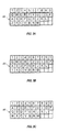
- FIG. 3A illustrates an exemplary QWERTY keyboard layout
- FIG. 3B illustrates an exemplary QWERTZ keyboard layout
- FIG. 3C illustrates an exemplary AZERTY keyboard layout
- FIG. 4A is a partial see-through view of an example handheld electronic device in a compact configuration
- FIG. 4B is a partial see-through view of the example handheld electronic device depicted in FIG. 4A showing the device in an expanded configuration;
- FIG. 4C is a partial see-through view of the example handheld electronic device depicted in FIG. 4A showing the device in an extended configuration;
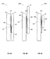
- FIG. 5A is a cross-sectional side view of the handheld device configured according to the present application in a compact configuration
- FIG. 5B is a cross-sectional side view of the handheld device depicted in FIG. 5A in a translated configuration
- FIG. 6A is a partial see-through view of another example handheld electronic device in a compact configuration
- FIG. 6B is a partial see-through view of the another example handheld electronic device depicted in FIG. 6A in a translated configuration
- FIG. 6C is a partial see-through view of the another example handheld electronic device depicted in FIG. 6A in an expanded configuration
- FIG. 6D is a partial see-through view of the another example handheld electronic device depicted in FIG. 6A in an expanded and illustrating a coupler engaged with one of two tracks;
- FIG. 6E is a partial see-through view of the another example handheld electronic device depicted in Fig. 6D illustrating the coupler engaged with the other of the two tracks;
- FIG. 7A is a partial see-through view of yet another example handheld electronic device in a translated configuration and illustrating a T-shaped coupler in a translated configuration;
- FIG. 7B is a partial see-through view of the yet another example handheld electronic device depicted in FIG. 7A in a translated configuration
- FIG. 7C is a partial see-through view of the yet another handheld electronic device depicted in FIG. 7A in an expanded configuration
- FIG. 8A is a cross-sectional side view of the handheld device configured according to the present application in a compact configuration and illustrating a coupler mounted to a slider;
- FIG. 8B is a cross-sectional side view of the handheld device depicted in FIG. 8A in a translated configuration
- FIG. 8C is a cross-sectional side view of the handheld device depicted in FIG. 8A in an expanded configuration
- FIG. 9A is a partial see-through view of another example of the handheld electronic device in a compact configuration
- FIG. 9B is a partial see-through view of another example of the handheld electronic device depicted in FIG. 9A in a translated configuration.
- FIG. 9C is a partial see-through view of another example of the handheld electronic device depicted FIG. 9A in an expanded configuration
- FIG. 1 An exemplary handheld electronic device 300 such as is shown in FIG. 1 and the device's cooperation in a wireless network 319 is exemplified in the block diagram of FIG. 2 .
- FIG. 2 An exemplary handheld electronic device 300 such as is shown in FIG. 1 and the device's cooperation in a wireless network 319 is exemplified in the block diagram of FIG. 2 .
- FIG. 2 An exemplary handheld electronic device 300 such as is shown in FIG. 1 and the device's cooperation in a wireless network 319 is exemplified in the block diagram of FIG. 2 .
- handheld electronic device describes a relatively small device that is capable of being held in a user's hand. It is a broader term that includes devices that are further classified as handheld electronic devices, which interact with a communications network.
- the electronic device 300 includes a microprocessor 338 that controls the operation of the electronic device 300.
- a communication subsystem 311 performs all communication transmission and reception with the wireless network 319.
- the microprocessor 338 further can be connected with an auxiliary input/output (I/O) subsystem 328 which can be connected to the device 300.
- the microprocessor 338 can be connected to a serial port (for example, a Universal Serial Bus port) 330 which can allow for communication with other devices or systems via the serial port 330.
- a display 322 can be connected to microprocessor 338 to allow for displaying of information to an operator of the device 300.
- the keyboard 332 can also be connected with the microprocessor 338.
- the electronic device 300 can include a speaker 334, a microphone 336, random access memory 326 (RAM), and flash memory 324, all of which may be connected to the microprocessor 338.
- a vibrator (not shown), which can be a vibrator motor, can be connected with the microprocessor 338 to generate vibrations in the electronic device 300.
- Other similar components may he provided an the device 300 as well and optionally connected to the microprocessor 338.
- Other communication subsystems 340 and other communication device subsystems 342 are generally indicated as being functionally connected with the microprocessor 338 as well.
- An example of a communication subsystem 340 is that of a short range communication system such as BLUETOOTHH® communication module or a WI-FI® communication module (a communication module in compliance with IEEE 802.11b) and associated circuits and components. Additionally, the microprocessor 338 is able to perform operating system functions and enables execution of programs on the electronic device 300. In some embodiments not all of the above components may be included in the electronic device 300. For example, in at least one embodiment the keyboard 332 is not provided as a separate component and is instead integrated with a touch-sensitive display.
- the electronic device 300 is equipped with components to enable operation of various programs, as shown in FIG. 2 .
- the flash memory 324 is enabled to provide a storage location for the operating system (not shown), device programs 358, and data.
- the operating system is generally configured to manage other programs 358 that are also stored in memory 324 and executable on the processor 338.
- the operating system honors requests for services made by programs 358 through predefined program 358 interfaces. More specifically, the operating system typically determines the order in which multiple programs 358 are executed on the processor 338 and the execution time allotted for each program 358, manages the sharing of memory 324 among multiple programs 358, handles input and output to and from other device subsystems 342, and so on.
- a user interface usually including the keyboard 332 and display screen 322, While in an exemplary embodiment the operating system is stored in flash memory 324, the operating system in other embodiments is stored in read-only memory (ROM) or similar storage element (not shown). As those skilled in the art will appreciate, the operating system, device program 358 or parts thereof may be loaded in RAM 326 or other volatile memory.
- ROM read-only memory
- the flash memory 324 contains programs 358 for execution on the electronic device 300 including an address book 352, a personal information manager (PIM) 354, and the device state 350. Furthermore, programs 358 and other information 356 including data can be segregated upon storage in the flash memory 324 of the electronic device 300.
- PIM personal information manager
- the electronic device 300 When the electronic device 300 is enabled for two-way communication within the wireless communication network 319, it sends and receives signals from a mobile communication service.
- Examples of communication systems enabled for two-way communication include, but are not limited to, the General Packet Radio Service (GPRS) network, the Universal Mobile Telecommunication Service (UMTS) network, the Enhanced Data for Global Evolution (EDGE) network, the Code Division Multiple Access (CDMA) network, High-Speed Packet Access (HSPA) networks, Universal Mobile Telecommunication Service Time Division Duplexing (UMTS-TDD), Ultra Mobile Broadband (UMB) networks, Worldwide Interoperability for Microwave Access (WiMAX), and other networks that can be used for data and voice, or just data or voice.
- GPRS General Packet Radio Service
- UMTS Universal Mobile Telecommunication Service
- EDGE Enhanced Data for Global Evolution
- CDMA Code Division Multiple Access
- UMTS-TDD Universal Mobile Telecommunication Service Time Division Duplexing
- UMB Ultra Mobile Broadband
- the electronic device 300 may require a unique identifier to enable the electronic device 300 to transmit and receive signals from the communication network 319. Other systems may not require such identifying information.
- GPRS, UMTS, and EDGE use a Subscriber Identity Module (SIM) in order to allow communication with the communication network 319.
- SIM Subscriber Identity Module
- RUIM Removable User Identity Module
- the RUIM and SIM card can be used in a multitude of different electronic devices 300.
- the electronic device 300 can operate some features without a SIM/RUIM card, but a SIM/RUIM card is necessary for communication with the network 319.
- a SIM/RUIM interface 344 located within the electronic device 300 allows for removal or insertion of a SIM/RUIM card (not shown).
- the SIM/RUIM card features memory and holds key configurations 351, and other information 353 such as identification and subscriber related information. With a properly enabled electronic device 300, two-way communication between the electronic device 300 and communication network 319 is possible.
- the two-way communication enabled electronic device 300 is able to both transmit and receive information from the communication network 319.
- the transfer of communication can be from the electronic device 300 or to the electronic device 300.
- the electronic device 300 in the presently described exemplary embodiment is equipped with an integral or internal antenna 318 for transmitting signals to the communication network 319.
- the electronic device 300 in the presently described exemplary embodiment is equipped with another antenna 316 for receiving communication from me communication network 319.
- These antennae 316, 318 in another exemplary embodiment are combined into a single antenna (not shown).
- the antenna or antennae 316, 318 in another embodiment are externally mounted on the electronic device 300.
- the electronic device 300 When equipped for two-way communication, the electronic device 300 includes a communication subsystem 311. As is understood in the art, this communication subsystem 311 supports the operational needs of the electronic device 300.
- the subsystem 311 includes a transmitter 314 and receiver 312 including the associated antenna or antennae 316, 318 as described above, local oscillators (LOs) 313, and a processing module 320 which in the presently described exemplary embodiment is a digital signal processor (DSP) 320.
- DSP digital signal processor
- communication by the electronic device 300 with the wireless network 319 is any type of communication that both the wireless network 319 and electronic device 300 are enabled to transmit, receive and process. In general, these can be classified as voice and data.
- Voice communication generally refers to communication in which signals for audible sounds are transmitted by the electronic device 300 through the communication network 319.
- Data generally refers to all other types of communication that the electronic device 300 is capable of performing within the constraints of the wireless network 319.
- the included auxiliary I/O subsystem 328 can take the form of a variety of different navigation tools such as a trackball 121 (shown in at least FIG. 1B ) based device or a joystick, just as examples. These navigation tools can be located on the front of the device 300 but may be located on any exterior face of the device 300.
- Other auxiliary I/O devices can include external display devices and externally connected keyboards (not shown). While the above examples have been provided in relation to the auxiliary I/O subsystem 328, other subsystems capable of providing input or receiving output from the handheld electronic device 300 are considered within the scope of this disclosure. Additionally, other keys may be placed along the side of the device 300 to function as escape keys, volume control keys, scrolling keys, power switches, or user programmable keys, and may likewise be programmed accordingly.
- the handheld electronic device 300 comprises a lighted display 322 located above a keyboard 332 suitable for accommodating textual input to the handheld electronic device 300 when in an operable configuration. As shown, the device 300 can transition to different configurations in which the display panel 10 and keyboard panel 120 are arranged in different spatial relationships.
- the present handheld electronic device 300 preferably includes a trackball 121 which is exteriorly located upon the keyboard panel 120 of the device 300. Its front location can be advantageous because it makes the tool easily thumb-actuable like the keys of the keyboard 332.
- the trackball 121 can instruct screen cursor movement in substantially any direction, as well as act as an when the ball 121 is depressed like a button.
- the placement of the trackball 121 can be above the keyboard 332 and below the display screen 322; here, it can avoid interference during keyboarding and does not block the user's view of the display screen 322 during use.
- FIG. 1A illustrates an example of the handheld electronic device 300 in a compact configuration 1000.
- the handheld electronic device 300 can be used in a telephone mode, a camera mode, browsing mode or the like.
- the display screen 322 on the display panel 10 can be held such that the display screen 322 is in a portrait or landscape orientation.
- only display panel 10, along with associated componentry such as the display screen 322, are visible.
- the keyboard panel which can have the keyboard, the navigational input device, function and other inputs, is concealed in the compact configuration 1000.
- FIG. 1B shows the handheld electronic device 300 in a translated configuration 2000.
- a keyboard panel 120 is exposed.
- the keyboard panel 120 can bear a keyboard 332 to allow text entry or phone key entry.
- the keyboard 332 can be coupled to the keyboard panel 120 in a variety of ways.
- the keyboard 332 can be mounted such that a portion of the keyboard panel 120 overlays the keyboard 332.
- the keyboard 332 can be mounted to the keyboard panel 120 at a rear side of the keyboard 332.
- switches or other electrical connections can be prodded between the keyboard 332 and the keyboard panel 120, thereby coupling the keyboard 332 to the keyboard panel 120.
- a navigational input device such as a trackball 121
- a navigational input device can also be coupled on the keyboard panel 120 to control a cursor that may be displayed on the lighted display 322.
- This coupling can be similar to that of keyboard 332 and the keyboard panel 120.
- the display 322 is in a portrait orientation such that the length of the display screen is greater than its width. In other embodiments, the display 322 can be arranged such that it is in a landscape orientation in the translated configuration 2000.
- the translated configuration 2000 can accommodated a telephone mode of operation, a portrait viewing mode, and other operational modes.
- FIG. 1C illustrates the handheld electronic device 300 in an expanded configuration 3000.
- the keyboard panel 120 is exposed, allowing access to the keyboard 322 and navigational input 121.
- the display 322 is in a landscape orientation in relation to the keyboard panel 120 and can be used in a word-processing mode, a messaging mode, an internet mode, or the like.
- the device 300 When the device 300 is configured as illustrated, it resembles a t-shape in the expanded configuration 3000.
- the centerpoint 150 of the display panel 10 is positioned closer to the centerpoint 160 of the keyboard pane! 120, as compared with the positions of the centerpoints 150, 160 in the translated configuration.
- the device 300 can be more compact and ergonomic, This is desirable as handheld electronic devices 300 are being used frequently in several different environmental settings that make a more ergonomic device desirable.
- This repositioning can also provide for a lower center of gravity of the display panel 10 in the expanded configuration 3000 thereby preventing accidental release from a user's hand or hands when the electronic device 300 is cradled in the user's hand or hands.
- the distance between the bottom of the display screen 322 and the keyboard 332 is substantially similar in both the portrait and landscape orientations of the display screen 322.
- FIGS. 4A-4C illustrate one exemplary embodiment of the handheld electronic device 300 transitionable between different configurations.
- the outlines of the display panel 10 are shown in order to provide a see-through view such that disclosure of the coupling of the two panels can be more fully illustrated.
- the keyboard 332 is shown on the keyboard panel 120 for reference purposes. While the keyboard 332 has the configuration as described above, other keyboard configurations can be used instead.
- the alphabetic keys of the keyboard can be arranged with one letter per alphabetic key. As illustrated a majority of the alphabetic keys have multiple letters per alphabetic key.
- the handheld electronic device 300 has a keyboard panel 120 shaped to form a slot 410 and a display panel 10, coupled by a coupler 400.
- the coupler 400 can provide for rotary coupling, as will be described below, of the display panel 10 and the keyboard panel 120.
- the display panel 10 is positioned adjacent to and in substantial parallel orientation with the keyboard panel 120 in a compact configuration 1000. While in the illustrated example, the display panel 10 and keyboard panel 120 are substantially similar in shape and size, in other embodiments, the keyboard panel 120 and display panel 10 can be of different sizes and shapes.
- FIG. 4B illustrates the handheld device 300 in a translated configuration 2000. There, the coupler 400 slidingly engages the slot 410 during transition from the compact configuration 1000 to the translated configuration 2000.
- FIG. 4C illustrates the handheld device 300 in an expanded configuration 3000. The display panel 10 rotates about the coupler 400 during transition between the translated configuration 2000 and the expanded configuration 3000.
- the coupler 400 can be coupled to the back 11 of the display panel 10, as illustrated. In other embodiments, the coupler 400 can be coupled to the front 122 of the keyboard panel 120. Additionally, the word coupled as used herein contemplates that the listed components can be directly connected, connected through to each other through additional components, or some combination thereof. Additionally, the coupling of the components can be such that the coupling can be of a removable nature.
- the handheld device 300 can also include a resilient biasing member 420 coupled to the keyboard panel 120 and the coupler 400. The resilient biasing member 420 can be coupled at one end of the member 420 to at about one end of the keyboard panel 120 and at an opposite end of the member 420 to the coupler 400.
- the resilient biasing member 420 can be coupled to the coupler 400 at about a centerpoint of the coupler 400. As the coupling of the resilient biasing member 420 to the coupler 400 is at a top face, but in other embodiments the coupling can be at other locations on the coupler 400. As illustrated, the distal end of the resilient member 420 is coupled to an end of the keyboard panel 120, and the end of the resilient member 420 is coupled to the centerpoint of the coupler 400. The end of the keyboard panel 120 can be a top end of the keyboard panel 120. In general, the top end refers to the portion of the keyboard panel 120 located on a side opposite of the centerpoint 160 from the keyboard 332. As illustrated, the resilient member 420 is coupled to an upper left portion, in relation to the keyboard 332 when in a text entry orientation, of the keyboard panel 120.
- the handheld device 300 depicted in FIGS. 4A-4C also includes a rotation control mechanism 430 that promotes smooth and controlled transitioning between the translated 2000 and expanded 3000 configurations.
- An example of such rotation control mechanism 430 can include at least one cord 440, where one end, such as the distal end, of the cord 440 is coupled to the keyboard panel 120 and another end, such as a proximal end, of the cord 440 is coupled to the coupler 400.
- the device 300 is in the compact configuration 1000 and the cord 440 of the rotation control mechanism 430 is loose, and the resilient member 420 is unstretched.
- the user slides the display panel 10 upward to expose the keyboard panel 120, which can have a keyboard 332, input keys, navigation input devices, or the like.
- the coupler 400 slides to the top of the slot 410 of the keyboard panel 120, as shown in FIG. 4B .
- the sliding motion extends the cord 440 of the rotation control mechanism 430 and compresses and relaxes the resilient member 420.
- the display panel 10 When the device 300 is transitioned from the translated configuration 2000 to the expanded configuration 3000, the display panel 10 can be rotated clockwise or counter-clockwise. With two cords 440, 450 as depicted in FIGS. 4B and 4C , the display panel 10 can rotate in a clockwise or counter-clockwise direction. In the illustrated embodiment of FIG. 4C , the display panel 10 is rotated in a clockwise direction. As the display panel 10 is rotated, the coupler 400 winds one of the cords 440, 450 of the rotation control mechanism 430. As the cord winds around the rotation control mechanism 430, the coupler 400 slides down the slot 410 from its position, in the translated configuration 2000, near the top of the slot 410.
- the rotation of the display panel 10 winds one cord 450 around the coupler 400 and loosens and slackens the other cord 440 of the rotation control mechanism 430.
- the cord 450 on the left hand side is wound around the rotation control mechanism 430 as the display panel 10 is rotated in a clockwise direction. If the display panel were rotated in a counter-clockwise direction, the right hand cord 440 is wound around the rotation control mechanism 430 and the left hand cord 450 is slackened.
- the centerpoint 150 of the display panel 10 moves closer to the centerpoint 160 of the keyboard panel 120 in the expanded configuration 3000 as compared to the translated configuration 2000.
- FIG. 5A and 5B are side cross-sectional views of the device 300 depicted in FIGS. 4A-4C .
- FIG. 5A shows the device 300 in a compact configuration 1000, where the cords 440, 450 of the rotation control mechanism 430 arc loose.
- FIG. 5B shows the device 300 in an expanded configuration 3000, where one of the cords 440, 450 of the rotation control mechanism 430 are taut until one of the cords 450 is wound around the coupler 400 when the display panel 10 is rotated.
- FIGS. 6A-6C illustrate another exemplary embodiment of the handheld device 300 transitionable between different configurations.
- the outlines of the display panel 10 are shown in order to provide a see-through view such that disclosure of the coupling of the two panels can be more fully illustrated.
- the keyboard 332 is shown on the keyboard panel 120 for reference purposes. While the keyboard 332 has the configuration as described above, other keyboard configurations can be used instead.
- the alphabetic keys of the keyboard can be arranged with one letter per alphabetic key. As illustrated a majority of the alphabetic keys have multiple letters per alphabetic key.
- FIG. 6A illustrates a handheld electronic device 300 having a display panel 10, a keyboard panel 120 with the display panel 10 positioned adjacent to and in substantial parallel orientation with the keyboard panel 120 in a compact configuration 1000, A slot 410 is formed on the front 122 of the keyboard panel 120.
- the device 300 can also include a coupler 400 having a plurality of teeth 500.
- the coupler can be located at a rear of the display panel 10. In other embodiments, the coupler 400 can be coupled to the front of the keyboard panel.
- the coupler 400 slidingly engages the slot 410 during transition from the compact configuration 1000 to a translated configuration 2000.
- the coupler 400 couples the display panel 10 with the keyboard panel and can be coupled to the back 11 of the display panel 10.
- At least one track 510 is included that also has a plurality of teeth 520.
- the at least one track 510 is substantially parallel to the slot 410 and is positioned such that the at least one track 510 engages the coupler 400 as the display panel 10 rotates.
- the coupler 400 is configured such that a top and bottom of the coupler 400 rotate in relation to one another, thereby accommodating the rotation of the display panel 10 in relation to the keyboard panel 120.
- the teeth 500 of the coupler 400 do not engage the teeth 520 of the at least one track 510.
- the display panel 10 slides upward and the coupler 400 slides upward in the slot 410.
- the coupler 400 is moved to approximately the top of the slot 410 and remains non-engaged to the at least track 510.
- the keyboard panel 120 is exposed which can expose a keyboard, a navigational input key, or other types of input keys.
- the display panel 10 is rotated with respect to the keyboard panel 120.
- This rotation of the display panel 10 with respect to the keyboard panel 120 can be about the coupler 400.
- the coupler 400 slides down the slot 410, and the teeth 500 of the coupler 400 engage or mesh with the teeth 520 of the track 510.
- the device 300 can be rotated either clockwise or counter clockwise.
- FIG. 6 shows the device rotated clockwise.
- the centerpoint 150 of the display panel 10 moves closer to the centerpoint 160 of the keyboard panel 120 in the expanded configuration 3000 as compared to the translated configuration 2000.
- FIGS. 6D and 6E show further embodiment of the device 300 having a coupler 400 with teeth 500.
- FIGS. 6D and 6E show two tracks 510 having a plurality of teeth 520.
- One of the tracks 510 is located on a left side of the coupler 400, and the other of the tracks 510 is located on the right side of the coupler.
- the movement of the coupler 400 in the compact configuration 1000 to the translated configuration 2000 is the same as described above with respect to a device 300 having one track 510.
- the device 300 can be configured to rotate both clockwise and counter-clockwise into an expanded configuration 3000, In FIG. 6D , the device 300 is rotated clockwise into the expanded configuration 3000. During this transition, the teeth 500 of the coupler 400 engage or mesh with the teeth 520 of the track 510 on the left side of the slot 410. In FIG. 6E , the device is rotated counter-cloekwise into the expanded configuration 300.
- the teeth 500 of the coupler 400 engage or mesh with the teeth 520 of the track 510 on the right side of the slot 410.
- the centerpoint 150 of the display panel 10 moves closer to the centerpoint 160 of the keyboard panel 120 in the expanded configuration 3000 as compared to the translated configuration 2000.
- the coupler 400 can have an outer perimeter that approximates a sector of a circle.
- the sector can be approximately one-quarter of the circle.
- the coupler 400 can take the form of shapes other than a sector of a circle, such as a triangle or a cone or an oblong shape.
- FIGS. 7A-7C show another exemplary embodiment of the device 300 transitionable between different configurations.
- the outlines of the display panel 10 are shown in order to provide a see-through view such that disclosure of the coupling of the two panels can be more fully illustrated.
- the keyboard 332 is shown on the keyboard panel 120 for reference purposes. While the keyboard 332 has the configuration as described above, other keyboard configurations can be used instead.
- the alphabetic keys of the keyboard can be arranged with one letter per alphabetic key. As illustrated a majority of the alphabetic keys have multiple letters per alphabetic key.
- FIG. 7A illustrates a handheld electronic device 300 having a display panel 10 greater in length than width.
- the device also has a lengthwise oriented centerline 700 that is substantially parallel with the length of the display panel 10.
- a t-shaped slot 600 is formed on a front 122 of the keyboard panel 120.
- the t-shaped slot 600 has a first portion 610 having a first size and oriented substantially parallel with the lengthwise oriented centerline 700.
- the t-shaped slot 600 also has a second portion 620 having a second size and oriented substantially perpendicular with the first portion 610.
- the size of the slot can be a width of the slot. In other embodiments, other configurations of relative sizes can be constructed such that the first portion 610 accommodates both the first surface 660 and second surface 650 of the cam 640.
- the device 300 can also include a cam 640 coupled to the back 11 of the display panel 10.
- the cam 640 has a first surface 660 and a second surface 650.
- the first surface 660 of the cam 640 is sized such that the first surface 660 slidingly engages with the first portion 610 of the t-shaped slot 600 and the second surface 650 of the cam 640 slidngly engages with the second portion 620 of the t-shaped slot 600 when the device is rotated into the expanded configuration 3000 depicted in FIG. 7C .
- the cam 640 can also include a connecting member 670.
- the connecting member 670 couples the first surface 660 to the second surface 650 of the cam such that the second surface 650 is spaced a distance from the first surface 660.
- the connecting member 670 can also have a length of at least the width of the second surface 650.
- the connecting member 670 can have a portion with a width less than size of the second portion 620 of the t-shaped slot 600. This allows the second surface 650 of the cam 640 to slide within the second portion 620 of the t-shaped slot 600.
- the resilient member 630 can be coupled to the keyboard panel at a first distal end 710 of the biasing member 630 and can be coupled to the centerpoint of the first surface 600 at a second proximal end 720 of the biasing member 630.
- the first end 710 of the biasing member 630 is coupled to the keyboard panel 120 at between the second portion 620 of the t-shaped slot 600 and a proximate end of the keyboard panel 120.
- the cam 640 engages the first portion 610 of the t-shaped slot 600 and the biasing member 630 is relaxed.
- the cam 640 slides upward in the first portion 610 of the t-shaped slot 600 and the biasing member 630 initially resists the motion and later encourages the sliding motion as it passes over a point at which substantially no force is exerted from the biasing member 630.
- the first surface 660 and second surface 650 of the cam 640 are located in the first portion 610 of the t-shaped slot 600.
- the second surface 650 of the cam 640 slideably engages the second portion 620 of the t-shaped slot 600, pulling the first surface 610 of the cam out of the top of the first portion 610 and into the center of the t-shaped slot 600.
- the display panel 10 may be rotated either clockwise or counter clockwise.
- the device 300 is in an expanded configuration 3000 as a result of clockwise rotation.
- the device 300 can be configured for counter-clockwise rotation.
- the second surface 650 of the cam 640 slideably engages the right arm of the t-shaped slot 600.
- the centerpoint 150 of the display panel 10 is closer to the centerpoint 160 of the keyboard panel 120 in the expanded configuration 3000 as compared to the position of the centerpoint 150 of the display panel 10 in relation to the keyboard panel 120 in the translated configuration 2000.
- the t-shape can have just three arms, where two of the arms are aligned parallel to the centerline 700 of the device 300. And the third arm is aligned perpendicular to the centerline 700.
- the device 300 would only be configured for one type of rotation into the expanded configuration 3000: either clockwise or counter-clockwise rotation. For example, if the arm perpendicular to centerline 700 was positioned to the left of the centerline 700, the device 300 would only allow for clockwise rotation into the expanded configuration 3000. Alternatively, if the arm perpendicular to the centerline 700 was located to the right of the centerline 700, the device would only be configured for counter-clockwise rotation into the expanded configuration 3000.
- FIGS. 8A-8C illustrate another exemplary embodiment of the handheld device 300 transitionable between different configurations.
- the example device 300 illustrated therein has a slider 820 that connects the display panel 10 to the keyboard panel 120 and alows for translated movement of the display panel 10 into the translated configuration 2000.
- the display panel 10 is connected to the slider 820 by the coupler 400, which is mounted on the slide pad 800 of the slider 820.
- the coupler 400 As the device 300 is transitioned from the compact configuration 1000 to the translated configuration 2000, the slide pad 800 slides along the sides of the slider 820.
- the couple 400 travels upward along with the display panel 10, thereby exposing a portion of the keyboard panel 120.
- the display panel 10 is rotated.
- the coupler 400 urges the slide pad 800 to slide the down the slider 820 so that the centerpoint of the display panel 10 is closer to the centerpoint of the keyboard panel 120 in the expanded configuration 3000 as compared to the position of the centerpoint of the display panel 10 in relation to the keyboard panel 120 in the translated configuration 2000.
- FIGS. 8A-8C specifically illustrate a device 300 having a coupler 400 mounted on a slider 820 and coupled to a rotation control mechanism by a cord 440.
- the coupler 400 thereby urging the slide pad 800 to slide down the slider 820 as the device 300 is transitioned from the translated configuration 1000 to the expanded configuration 3000.
- the centerpoint of the display panel 10 is closer to the centerpoint of the keyboard panel 120 in the expanded configuration 3000 as compared to the position of the of the display panel 10 in relation to the keyboard panel 120 in the translated configuration 2000.
- the distance between the bottom of the display screen and the keyboard is substantially similar in both the translated configuration 2000 and the expanded configuration 3000.
- FIOS. 9A-9C illustrate another exemplary embodiment of the handheld device 300 transitionable between different configurations.
- the example device 300 illustrated therein has a spring loaded mechanism 920, such as a spring load bias, a slider, or the like.
- FIGS. 9A-9C illustrate a spring loaded mechanism that is a spring 920.
- the spring loaded mechanism 920 allows for translated movement of the display panel 10 from a compact configuration 1000 into a translated configuration 2000.
- the handheld device 300 can have one of more protrusions 910 on the rear face of the display panel 10 near the centerpoint 150 of the display panel 10. In the embodiment illustrated in FIGS.
- the handheld device 300 can also have one or more apertures 900 on the front face of the keyboard panel 120. In the embodiment illustrated in FIGS. 9A-9C , there are two apertures 900 are located above the centerpoint 160 of the keyboard panel 120 and symmetrically about a vertical centerline 930 of the handheld device 300. The apertures 900 are sized to receive the protrusions 910 when the display panel 10 is rotated into the expanded configuration 3000. The transition of the handheld device 300 will now be discussed,
- FIG. 9A illustrates the handheld device 300 in a compact configuration 1000.
- the spring loaded mechanism 920 is loaded to keep the handheld device 300 in a closed compact configuration 1000.
- FIG. 9B the display panel 10 is slid upward into the translated configuration 2000. During this transition, the spring leaded mechanism 920 is fully open to hold the handheld device 300 in the translated configuration 2000.
- the display panel 10 is rotated. When the display panel is rotated 10, the spring loaded mechanism 920 is partially open, and the protrusions 910 are rotated. When the protrusions 910 are aligned with the apertures 900, the protrusions 910 securely fit within the apertures 900 to keep the handheld device 300 in the expanded configuration 3000 shown in FIG.
- the apertures 900 can include detents to provide further assurance that the provisions 910 are securely fit within the apertures 900.
- the keyboard panel 120 can have keyboard 332 for entering text or other types of input.
- the keyboard 332 can have keys bearing alphabetic indicia. These alphabetic indicia can be arranged in a variety of layouts 44, examples of which are shown in FIGS. 3A-3C .
- the keyboard 332 can have a QWERTY layout ( FIG. 3A ), a QWERTZ layout ( FIG. 3B ), an AZERTY layout ( FIG. 3C ), or other similar keyboard layout 44.
- the keys of the keyboard can be arranged such that the keys having alphabetic indicia associated therewith can be associated with a single alphabetic character or a plurality of alphabetic characters.
- the keys can be associated with numbers, which can be arranged in a telephone arrangement according to ITU standard E.161, as illustrated in at least FIG. 1B .
- the device 300 can have a microprocessor 338 configured such that transitions between each of the configurations launch different device modes, applications, or functions of the device 300.
- the device 300 in the compact configuration 1000, the device 300 can be automatically set to a camera mode, a game mode, or a previewing mode.
- the device 300 when the device 300 is transitioned into the compact configuration 1000, the device 300 can automatically launch a camera application.
- the device 300 In the translated configuration 2000, the device 300 can be automatically set to a telephone mode.
- the device 300 can automatically exit a camera or video application and automatically launch a telephone action.
- the device 300 can be automatically set to a landscape viewing mode, an email mode, or a text entry mode. Alternatively, when the device 300 is transitioned into the expanded configuration 300, the device 300 can automatically close a telephone application and launch an email function or word-processing function.
- the device 300 can have a microprocessor 338 that is configured to automatically change the orientation of an image or display on the display screen 322. For example, when the device 300 is transitioned from the compact configuration 1000 to the translated configuration 2000, the orientation of the image or display that was on the display screen 322 in the compact configuration 1000 can be changed to a portrait orientation in the translated configuration 2000. Then, if the device 300 is rotated into the expanded configuration 3000, the microprocessor 338 can again change the orientation of the image or display on the display screen 332 in the translated configuration 2000 to a landscape orientation in the expanded configuration 3000.
Abstract


Description
- The present disclosure relates generally to handheld electronic devices. More specifically, the present disclosure relates to handheld electronic devices capable of transitioning between different configurations,
- With the proliferation of communication systems, compatible handheld electronic devices are becoming more prevalent, as well as advanced. Examples of electronic devices include both handheld electronic devices as well as larger devices such electronic devices include both handheld electronic devices as well as larger devices such as laptop computers, desktop computers and the like. These devices are capable of sending and receiving a variety of different messages including but not limited to short message service (SMS), multimedia message service (MMS), emails, voice messages, and the like.
- Whereas in the past such handheld electronic devices typically accommodated either voice transmission (cell phones), or text transmission (pagers and PDAs), today's consumer often demands a combination device capable of performing both types of transmissions, including even sending and receiving e-mail. Furthermore, these higher-performance devices can also be capable of sending and receiving other types of data including that which allows the viewing and use of Internet websites. These higher level functionalities necessarily require greater user interaction with the devices through included user interfaces (UIs) which may have originally been designed to accommodate making and receiving telephone calls and sending messages over a related Short Messaging Service (SMS). As might be expected, suppliers of such mobile electronic devices and the related service providers are anxious to meet these customer requirements, but the demands of these more advanced functionalities have in many circumstances rendered the traditional user interfaces unsatisfactory, a situation that has caused designers to have to improve the UIs through which users input information and control these sophisticated operations.
- Embodiments of the present application will now be described, by way of example only, with reference to the attached Figures, wherein:
- FIC. 1A is a handheld electronic device configured according to the present disclosure in a compact configuration;
-
FIG. 1B is a handheld electronic device configured according to the present disclosure in a translated configuration; - FIG. IC is a handheld electronic device configured according to the present disclosure in an expanded configuration;
-
FIG. 2 is a block diagram representing a wireless handheld electronic device interacting in a communication network; -
FIG. 3A illustrates an exemplary QWERTY keyboard layout; -
FIG. 3B illustrates an exemplary QWERTZ keyboard layout; -
FIG. 3C illustrates an exemplary AZERTY keyboard layout; -
FIG. 4A is a partial see-through view of an example handheld electronic device in a compact configuration; -
FIG. 4B is a partial see-through view of the example handheld electronic device depicted inFIG. 4A showing the device in an expanded configuration; -
FIG. 4C is a partial see-through view of the example handheld electronic device depicted inFIG. 4A showing the device in an extended configuration; -
FIG. 5A is a cross-sectional side view of the handheld device configured according to the present application in a compact configuration; -
FIG. 5B is a cross-sectional side view of the handheld device depicted inFIG. 5A in a translated configuration; -
FIG. 6A is a partial see-through view of another example handheld electronic device in a compact configuration; -
FIG. 6B is a partial see-through view of the another example handheld electronic device depicted inFIG. 6A in a translated configuration; -
FIG. 6C is a partial see-through view of the another example handheld electronic device depicted inFIG. 6A in an expanded configuration; -
FIG. 6D is a partial see-through view of the another example handheld electronic device depicted inFIG. 6A in an expanded and illustrating a coupler engaged with one of two tracks; -
FIG. 6E is a partial see-through view of the another example handheld electronic device depicted inFig. 6D illustrating the coupler engaged with the other of the two tracks; -
FIG. 7A is a partial see-through view of yet another example handheld electronic device in a translated configuration and illustrating a T-shaped coupler in a translated configuration; -
FIG. 7B is a partial see-through view of the yet another example handheld electronic device depicted inFIG. 7A in a translated configuration; -
FIG. 7C is a partial see-through view of the yet another handheld electronic device depicted inFIG. 7A in an expanded configuration; -
FIG. 8A is a cross-sectional side view of the handheld device configured according to the present application in a compact configuration and illustrating a coupler mounted to a slider; -
FIG. 8B is a cross-sectional side view of the handheld device depicted inFIG. 8A in a translated configuration; -
FIG. 8C is a cross-sectional side view of the handheld device depicted inFIG. 8A in an expanded configuration; -
FIG. 9A is a partial see-through view of another example of the handheld electronic device in a compact configuration; -
FIG. 9B is a partial see-through view of another example of the handheld electronic device depicted inFIG. 9A in a translated configuration; and -
FIG. 9C is a partial see-through view of another example of the handheld electronic device depictedFIG. 9A in an expanded configuration, - An exemplary handheld
electronic device 300 such as is shown inFIG. 1 and the device's cooperation in awireless network 319 is exemplified in the block diagram ofFIG. 2 . These figures are exemplary only, and those persons skilled in the art will appreciate the additional elements and modifications necessary to make thedevice 300 work in particular network environments. - As used herein, the term handheld electronic device describes a relatively small device that is capable of being held in a user's hand. It is a broader term that includes devices that are further classified as handheld electronic devices, which interact with a communications network.
- As shown in the block diagram of
FIG. 2 , theelectronic device 300 includes amicroprocessor 338 that controls the operation of theelectronic device 300. Acommunication subsystem 311 performs all communication transmission and reception with thewireless network 319. Themicroprocessor 338 further can be connected with an auxiliary input/output (I/O)subsystem 328 which can be connected to thedevice 300. Additionally, in at least one embodiment, themicroprocessor 338 can be connected to a serial port (for example, a Universal Serial Bus port) 330 which can allow for communication with other devices or systems via theserial port 330. Adisplay 322 can be connected tomicroprocessor 338 to allow for displaying of information to an operator of thedevice 300. When theelectronic device 300 is equipped with akeyboard 332, which maybe physical or virtual, thekeyboard 332 can also be connected with themicroprocessor 338. Theelectronic device 300 can include aspeaker 334, amicrophone 336, random access memory 326 (RAM), andflash memory 324, all of which may be connected to themicroprocessor 338. Additionally, a vibrator (not shown), which can be a vibrator motor, can be connected with themicroprocessor 338 to generate vibrations in theelectronic device 300. Other similar components may he provided an thedevice 300 as well and optionally connected to themicroprocessor 338.Other communication subsystems 340 and othercommunication device subsystems 342 are generally indicated as being functionally connected with themicroprocessor 338 as well. An example of acommunication subsystem 340 is that of a short range communication system such as BLUETOOTHH® communication module or a WI-FI® communication module (a communication module in compliance with IEEE 802.11b) and associated circuits and components. Additionally, themicroprocessor 338 is able to perform operating system functions and enables execution of programs on theelectronic device 300. In some embodiments not all of the above components may be included in theelectronic device 300. For example, in at least one embodiment thekeyboard 332 is not provided as a separate component and is instead integrated with a touch-sensitive display. - Furthermore, the
electronic device 300 is equipped with components to enable operation of various programs, as shown inFIG. 2 . In an exemplary embodiment, theflash memory 324 is enabled to provide a storage location for the operating system (not shown),device programs 358, and data. The operating system is generally configured to manageother programs 358 that are also stored inmemory 324 and executable on theprocessor 338. The operating system honors requests for services made byprograms 358 throughpredefined program 358 interfaces. More specifically, the operating system typically determines the order in whichmultiple programs 358 are executed on theprocessor 338 and the execution time allotted for eachprogram 358, manages the sharing ofmemory 324 amongmultiple programs 358, handles input and output to and fromother device subsystems 342, and so on. In addition, operators can typically interact directly with the operating system through a user interface usually including thekeyboard 332 anddisplay screen 322, While in an exemplary embodiment the operating system is stored inflash memory 324, the operating system in other embodiments is stored in read-only memory (ROM) or similar storage element (not shown). As those skilled in the art will appreciate, the operating system,device program 358 or parts thereof may be loaded inRAM 326 or other volatile memory. - In one exemplary embodiment, the
flash memory 324 containsprograms 358 for execution on theelectronic device 300 including anaddress book 352, a personal information manager (PIM) 354, and thedevice state 350. Furthermore,programs 358 andother information 356 including data can be segregated upon storage in theflash memory 324 of theelectronic device 300. - When the
electronic device 300 is enabled for two-way communication within thewireless communication network 319, it sends and receives signals from a mobile communication service. Examples of communication systems enabled for two-way communication include, but are not limited to, the General Packet Radio Service (GPRS) network, the Universal Mobile Telecommunication Service (UMTS) network, the Enhanced Data for Global Evolution (EDGE) network, the Code Division Multiple Access (CDMA) network, High-Speed Packet Access (HSPA) networks, Universal Mobile Telecommunication Service Time Division Duplexing (UMTS-TDD), Ultra Mobile Broadband (UMB) networks, Worldwide Interoperability for Microwave Access (WiMAX), and other networks that can be used for data and voice, or just data or voice. For the systems listed above, theelectronic device 300 may require a unique identifier to enable theelectronic device 300 to transmit and receive signals from thecommunication network 319. Other systems may not require such identifying information. GPRS, UMTS, and EDGE use a Subscriber Identity Module (SIM) in order to allow communication with thecommunication network 319. Likewise, most CDMA systems use a Removable User Identity Module (RUIM) in order to communicate with the CDMA network. The RUIM and SIM card can be used in a multitude of differentelectronic devices 300. Theelectronic device 300 can operate some features without a SIM/RUIM card, but a SIM/RUIM card is necessary for communication with thenetwork 319. A SIM/RUIM interface 344 located within theelectronic device 300 allows for removal or insertion of a SIM/RUIM card (not shown). The SIM/RUIM card features memory and holdskey configurations 351, andother information 353 such as identification and subscriber related information. With a properly enabledelectronic device 300, two-way communication between theelectronic device 300 andcommunication network 319 is possible. - If the
electronic device 300 is enabled as described above or thecommunication network 319 does not require such enablement, the two-way communication enabledelectronic device 300 is able to both transmit and receive information from thecommunication network 319. The transfer of communication can be from theelectronic device 300 or to theelectronic device 300. In order to communicate with thecommunication network 319, theelectronic device 300 in the presently described exemplary embodiment is equipped with an integral or internal antenna 318 for transmitting signals to thecommunication network 319. Likewise theelectronic device 300 in the presently described exemplary embodiment is equipped with anotherantenna 316 for receiving communication from mecommunication network 319. Theseantennae 316, 318 in another exemplary embodiment are combined into a single antenna (not shown). As one skilled in the art would appreciate, the antenna orantennae 316, 318 in another embodiment are externally mounted on theelectronic device 300. - When equipped for two-way communication, the
electronic device 300 includes acommunication subsystem 311. As is understood in the art, thiscommunication subsystem 311 supports the operational needs of theelectronic device 300. Thesubsystem 311 includes atransmitter 314 andreceiver 312 including the associated antenna orantennae 316, 318 as described above, local oscillators (LOs) 313, and aprocessing module 320 which in the presently described exemplary embodiment is a digital signal processor (DSP) 320. - It is contemplated that communication by the
electronic device 300 with thewireless network 319 is any type of communication that both thewireless network 319 andelectronic device 300 are enabled to transmit, receive and process. In general, these can be classified as voice and data. Voice communication generally refers to communication in which signals for audible sounds are transmitted by theelectronic device 300 through thecommunication network 319. Data generally refers to all other types of communication that theelectronic device 300 is capable of performing within the constraints of thewireless network 319. - The included auxiliary I/
O subsystem 328 can take the form of a variety of different navigation tools such as a trackball 121 (shown in at leastFIG. 1B ) based device or a joystick, just as examples. These navigation tools can be located on the front of thedevice 300 but may be located on any exterior face of thedevice 300. Other auxiliary I/O devices can include external display devices and externally connected keyboards (not shown). While the above examples have been provided in relation to the auxiliary I/O subsystem 328, other subsystems capable of providing input or receiving output from the handheldelectronic device 300 are considered within the scope of this disclosure. Additionally, other keys may be placed along the side of thedevice 300 to function as escape keys, volume control keys, scrolling keys, power switches, or user programmable keys, and may likewise be programmed accordingly. - As may be appreciated from at least
FIGS. 1A and 1B , the handheldelectronic device 300 comprises a lighteddisplay 322 located above akeyboard 332 suitable for accommodating textual input to the handheldelectronic device 300 when in an operable configuration. As shown, thedevice 300 can transition to different configurations in which thedisplay panel 10 andkeyboard panel 120 are arranged in different spatial relationships. - Keys, typically of a push-button or push-pad nature, perform well as data entry devices but present problems to the user when they must also be used to affect navigational control over a screen-cursor. In order to solve this problem the present handheld
electronic device 300 preferably includes atrackball 121 which is exteriorly located upon thekeyboard panel 120 of thedevice 300. Its front location can be advantageous because it makes the tool easily thumb-actuable like the keys of thekeyboard 332. Thetrackball 121 can instruct screen cursor movement in substantially any direction, as well as act as an when theball 121 is depressed like a button. The placement of thetrackball 121 can be above thekeyboard 332 and below thedisplay screen 322; here, it can avoid interference during keyboarding and does not block the user's view of thedisplay screen 322 during use. -
FIG. 1A illustrates an example of the handheldelectronic device 300 in acompact configuration 1000. In thecompact configuration 1000, the handheldelectronic device 300 can be used in a telephone mode, a camera mode, browsing mode or the like. Additionally, thedisplay screen 322 on thedisplay panel 10 can be held such that thedisplay screen 322 is in a portrait or landscape orientation. In thiscompact configuration 1000, only displaypanel 10, along with associated componentry such as thedisplay screen 322, are visible. The keyboard panel, which can have the keyboard, the navigational input device, function and other inputs, is concealed in thecompact configuration 1000. -
FIG. 1B shows the handheldelectronic device 300 in a translatedconfiguration 2000. In the translatedconfiguration 2000, akeyboard panel 120 is exposed. Thekeyboard panel 120 can bear akeyboard 332 to allow text entry or phone key entry. Thekeyboard 332 can be coupled to thekeyboard panel 120 in a variety of ways. For example, thekeyboard 332 can be mounted such that a portion of thekeyboard panel 120 overlays thekeyboard 332. In another example, thekeyboard 332 can be mounted to thekeyboard panel 120 at a rear side of thekeyboard 332. Additionally, switches or other electrical connections can be prodded between thekeyboard 332 and thekeyboard panel 120, thereby coupling thekeyboard 332 to thekeyboard panel 120. Additionally, a navigational input device, such as atrackball 121, can also be coupled on thekeyboard panel 120 to control a cursor that may be displayed on the lighteddisplay 322. This coupling can be similar to that ofkeyboard 332 and thekeyboard panel 120. In the example translatedconfiguration 2000, thedisplay 322 is in a portrait orientation such that the length of the display screen is greater than its width. In other embodiments, thedisplay 322 can be arranged such that it is in a landscape orientation in the translatedconfiguration 2000. The translatedconfiguration 2000 can accommodated a telephone mode of operation, a portrait viewing mode, and other operational modes. -
FIG. 1C illustrates the handheldelectronic device 300 in an expandedconfiguration 3000. In the expandedconfiguration 3000, thekeyboard panel 120 is exposed, allowing access to thekeyboard 322 andnavigational input 121. Also, thedisplay 322 is in a landscape orientation in relation to thekeyboard panel 120 and can be used in a word-processing mode, a messaging mode, an internet mode, or the like. When thedevice 300 is configured as illustrated, it resembles a t-shape in the expandedconfiguration 3000. - In the expanded
configuration 3000, thecenterpoint 150 of thedisplay panel 10 is positioned closer to thecenterpoint 160 of the keyboard pane! 120, as compared with the positions of thecenterpoints centerpoint 150 of thedisplay panel 10 closer to thecenterpoint 160 of thekeyboard panel 120 in the expandedconfiguration 3000 as compared to the translatedconfiguration 2000, thedevice 300 can be more compact and ergonomic, This is desirable as handheldelectronic devices 300 are being used frequently in several different environmental settings that make a more ergonomic device desirable. This repositioning can also provide for a lower center of gravity of thedisplay panel 10 in the expandedconfiguration 3000 thereby preventing accidental release from a user's hand or hands when theelectronic device 300 is cradled in the user's hand or hands. Additionally, the distance between the bottom of thedisplay screen 322 and thekeyboard 332 is substantially similar in both the portrait and landscape orientations of thedisplay screen 322. - Examples of
devices 300 that transition between thecompact configuration 1000, translatedconfiguration 2000, and expandedconfiguration 3000 to achieve a more compact and ergonomic handheldelectronic device 300 will now be described. -
FIGS. 4A-4C illustrate one exemplary embodiment of the handheldelectronic device 300 transitionable between different configurations. InFIGS. 4A-4C , the outlines of thedisplay panel 10 are shown in order to provide a see-through view such that disclosure of the coupling of the two panels can be more fully illustrated. Thekeyboard 332 is shown on thekeyboard panel 120 for reference purposes. While thekeyboard 332 has the configuration as described above, other keyboard configurations can be used instead. For example, the alphabetic keys of the keyboard can be arranged with one letter per alphabetic key. As illustrated a majority of the alphabetic keys have multiple letters per alphabetic key. In this embodiment, the handheldelectronic device 300 has akeyboard panel 120 shaped to form aslot 410 and adisplay panel 10, coupled by acoupler 400. Thecoupler 400 can provide for rotary coupling, as will be described below, of thedisplay panel 10 and thekeyboard panel 120. As shown inFIG. 4A , thedisplay panel 10 is positioned adjacent to and in substantial parallel orientation with thekeyboard panel 120 in acompact configuration 1000. While in the illustrated example, thedisplay panel 10 andkeyboard panel 120 are substantially similar in shape and size, in other embodiments, thekeyboard panel 120 anddisplay panel 10 can be of different sizes and shapes.FIG. 4B illustrates thehandheld device 300 in a translatedconfiguration 2000. There, thecoupler 400 slidingly engages theslot 410 during transition from thecompact configuration 1000 to the translatedconfiguration 2000.FIG. 4C illustrates thehandheld device 300 in an expandedconfiguration 3000. Thedisplay panel 10 rotates about thecoupler 400 during transition between the translatedconfiguration 2000 and the expandedconfiguration 3000. - In
FIGS. 4A-4C , thecoupler 400 can be coupled to theback 11 of thedisplay panel 10, as illustrated. In other embodiments, thecoupler 400 can be coupled to thefront 122 of thekeyboard panel 120. Additionally, the word coupled as used herein contemplates that the listed components can be directly connected, connected through to each other through additional components, or some combination thereof. Additionally, the coupling of the components can be such that the coupling can be of a removable nature. Thehandheld device 300 can also include aresilient biasing member 420 coupled to thekeyboard panel 120 and thecoupler 400. Theresilient biasing member 420 can be coupled at one end of themember 420 to at about one end of thekeyboard panel 120 and at an opposite end of themember 420 to thecoupler 400. Theresilient biasing member 420 can be coupled to thecoupler 400 at about a centerpoint of thecoupler 400. As the coupling of theresilient biasing member 420 to thecoupler 400 is at a top face, but in other embodiments the coupling can be at other locations on thecoupler 400. As illustrated, the distal end of theresilient member 420 is coupled to an end of thekeyboard panel 120, and the end of theresilient member 420 is coupled to the centerpoint of thecoupler 400. The end of thekeyboard panel 120 can be a top end of thekeyboard panel 120. In general, the top end refers to the portion of thekeyboard panel 120 located on a side opposite of the centerpoint 160 from thekeyboard 332. As illustrated, theresilient member 420 is coupled to an upper left portion, in relation to thekeyboard 332 when in a text entry orientation, of thekeyboard panel 120. - The
handheld device 300 depicted inFIGS. 4A-4C also includes arotation control mechanism 430 that promotes smooth and controlled transitioning between the translated 2000 and expanded 3000 configurations. An example of suchrotation control mechanism 430 can include at least onecord 440, where one end, such as the distal end, of thecord 440 is coupled to thekeyboard panel 120 and another end, such as a proximal end, of thecord 440 is coupled to thecoupler 400. - In
FIG. 4A , thedevice 300 is in thecompact configuration 1000 and thecord 440 of therotation control mechanism 430 is loose, and theresilient member 420 is unstretched. As thedevice 300 is transitioned into the translatedconfiguration 2000, the user slides thedisplay panel 10 upward to expose thekeyboard panel 120, which can have akeyboard 332, input keys, navigation input devices, or the like. Thecoupler 400 slides to the top of theslot 410 of thekeyboard panel 120, as shown inFIG. 4B . The sliding motion extends thecord 440 of therotation control mechanism 430 and compresses and relaxes theresilient member 420. - When the
device 300 is transitioned from the translatedconfiguration 2000 to the expandedconfiguration 3000, thedisplay panel 10 can be rotated clockwise or counter-clockwise. With twocords FIGS. 4B and 4C , thedisplay panel 10 can rotate in a clockwise or counter-clockwise direction. In the illustrated embodiment ofFIG. 4C , thedisplay panel 10 is rotated in a clockwise direction. As thedisplay panel 10 is rotated, thecoupler 400 winds one of thecords rotation control mechanism 430. As the cord winds around therotation control mechanism 430, thecoupler 400 slides down theslot 410 from its position, in the translatedconfiguration 2000, near the top of theslot 410. When two cords are provided, the rotation of thedisplay panel 10 winds onecord 450 around thecoupler 400 and loosens and slackens theother cord 440 of therotation control mechanism 430. For example, thecord 450 on the left hand side is wound around therotation control mechanism 430 as thedisplay panel 10 is rotated in a clockwise direction. If the display panel were rotated in a counter-clockwise direction, theright hand cord 440 is wound around therotation control mechanism 430 and theleft hand cord 450 is slackened. As thecoupler 400 slides lower in theslot 410 during rotation, thecenterpoint 150 of thedisplay panel 10 moves closer to thecenterpoint 160 of thekeyboard panel 120 in the expandedconfiguration 3000 as compared to the translatedconfiguration 2000. -
FIG. 5A and 5B are side cross-sectional views of thedevice 300 depicted inFIGS. 4A-4C .FIG. 5A shows thedevice 300 in acompact configuration 1000, where thecords rotation control mechanism 430 arc loose.FIG. 5B shows thedevice 300 in an expandedconfiguration 3000, where one of thecords rotation control mechanism 430 are taut until one of thecords 450 is wound around thecoupler 400 when thedisplay panel 10 is rotated. -
FIGS. 6A-6C illustrate another exemplary embodiment of thehandheld device 300 transitionable between different configurations. InFIGS. 6A-6C , the outlines of thedisplay panel 10 are shown in order to provide a see-through view such that disclosure of the coupling of the two panels can be more fully illustrated. Thekeyboard 332 is shown on thekeyboard panel 120 for reference purposes. While thekeyboard 332 has the configuration as described above, other keyboard configurations can be used instead. For example, the alphabetic keys of the keyboard can be arranged with one letter per alphabetic key. As illustrated a majority of the alphabetic keys have multiple letters per alphabetic key.FIG. 6A illustrates a handheldelectronic device 300 having adisplay panel 10, akeyboard panel 120 with thedisplay panel 10 positioned adjacent to and in substantial parallel orientation with thekeyboard panel 120 in acompact configuration 1000, Aslot 410 is formed on thefront 122 of thekeyboard panel 120. Thedevice 300 can also include acoupler 400 having a plurality ofteeth 500. The coupler can be located at a rear of thedisplay panel 10. In other embodiments, thecoupler 400 can be coupled to the front of the keyboard panel. Thecoupler 400 slidingly engages theslot 410 during transition from thecompact configuration 1000 to a translatedconfiguration 2000. Thecoupler 400 couples thedisplay panel 10 with the keyboard panel and can be coupled to theback 11 of thedisplay panel 10. Additionally, at least onetrack 510 is included that also has a plurality ofteeth 520. The at least onetrack 510 is substantially parallel to theslot 410 and is positioned such that the at least onetrack 510 engages thecoupler 400 as thedisplay panel 10 rotates. In at least one embodiment, thecoupler 400 is configured such that a top and bottom of thecoupler 400 rotate in relation to one another, thereby accommodating the rotation of thedisplay panel 10 in relation to thekeyboard panel 120. - When the
device 300 is in thecompact configuration 1000, theteeth 500 of thecoupler 400 do not engage theteeth 520 of the at least onetrack 510. As thedevice 300 is transitioned from thecompact configuration 1000 to the translatedconfiguration 2000, thedisplay panel 10 slides upward and thecoupler 400 slides upward in theslot 410. In the translatedconfiguration 2000, thecoupler 400 is moved to approximately the top of theslot 410 and remains non-engaged to the at leasttrack 510. In, the translatedconfiguration 2000, thekeyboard panel 120 is exposed which can expose a keyboard, a navigational input key, or other types of input keys. - As shown in
FIG. 6C , to transition between the translatedconfiguration 2000 to the expandedconfiguration 300, thedisplay panel 10 is rotated with respect to thekeyboard panel 120. This rotation of thedisplay panel 10 with respect to thekeyboard panel 120 can be about thecoupler 400. As thedisplay panel 10 is rotated, thecoupler 400 slides down theslot 410, and theteeth 500 of thecoupler 400 engage or mesh with theteeth 520 of thetrack 510. Thedevice 300 can be rotated either clockwise or counter clockwise.FIG. 6 shows the device rotated clockwise. As thecoupler 400 slides lower in theslot 410 during rotation, thecenterpoint 150 of thedisplay panel 10 moves closer to thecenterpoint 160 of thekeyboard panel 120 in the expandedconfiguration 3000 as compared to the translatedconfiguration 2000. -
FIGS. 6D and 6E show further embodiment of thedevice 300 having acoupler 400 withteeth 500.FIGS. 6D and 6E show twotracks 510 having a plurality ofteeth 520. One of thetracks 510 is located on a left side of thecoupler 400, and the other of thetracks 510 is located on the right side of the coupler. - The movement of the
coupler 400 in thecompact configuration 1000 to the translatedconfiguration 2000 is the same as described above with respect to adevice 300 having onetrack 510. However, in adevice 300 having twotracks 510 with a plurality ofteeth 520, thedevice 300 can be configured to rotate both clockwise and counter-clockwise into an expandedconfiguration 3000, InFIG. 6D , thedevice 300 is rotated clockwise into the expandedconfiguration 3000. During this transition, theteeth 500 of thecoupler 400 engage or mesh with theteeth 520 of thetrack 510 on the left side of theslot 410. InFIG. 6E , the device is rotated counter-cloekwise into the expandedconfiguration 300. During counter-clockwise rotation, theteeth 500 of thecoupler 400 engage or mesh with theteeth 520 of thetrack 510 on the right side of theslot 410. As thedisplay panel 10 rotates thecenterpoint 150 of thedisplay panel 10 moves closer to thecenterpoint 160 of thekeyboard panel 120 in the expandedconfiguration 3000 as compared to the translatedconfiguration 2000. - In either of the embodiments in
FIGS. 6A-6C orFIGS. 6D-6E , thecoupler 400 can have an outer perimeter that approximates a sector of a circle. In further embodiment, the sector can be approximately one-quarter of the circle. However, thecoupler 400 can take the form of shapes other than a sector of a circle, such as a triangle or a cone or an oblong shape. -
FIGS. 7A-7C show another exemplary embodiment of thedevice 300 transitionable between different configurations. InFIGS. 7A-7C , the outlines of thedisplay panel 10 are shown in order to provide a see-through view such that disclosure of the coupling of the two panels can be more fully illustrated. Thekeyboard 332 is shown on thekeyboard panel 120 for reference purposes. While thekeyboard 332 has the configuration as described above, other keyboard configurations can be used instead. For example, the alphabetic keys of the keyboard can be arranged with one letter per alphabetic key. As illustrated a majority of the alphabetic keys have multiple letters per alphabetic key.FIG. 7A illustrates a handheldelectronic device 300 having adisplay panel 10 greater in length than width. The device also has a lengthwise orientedcenterline 700 that is substantially parallel with the length of thedisplay panel 10. A t-shapedslot 600 is formed on afront 122 of thekeyboard panel 120. The t-shapedslot 600 has afirst portion 610 having a first size and oriented substantially parallel with the lengthwise orientedcenterline 700. The t-shapedslot 600 also has asecond portion 620 having a second size and oriented substantially perpendicular with thefirst portion 610. As illustrated, the size of the slot can be a width of the slot. In other embodiments, other configurations of relative sizes can be constructed such that thefirst portion 610 accommodates both thefirst surface 660 andsecond surface 650 of thecam 640. - The
device 300 can also include acam 640 coupled to theback 11 of thedisplay panel 10. Thecam 640 has afirst surface 660 and asecond surface 650. Thefirst surface 660 of thecam 640 is sized such that thefirst surface 660 slidingly engages with thefirst portion 610 of the t-shapedslot 600 and thesecond surface 650 of thecam 640 slidngly engages with thesecond portion 620 of the t-shapedslot 600 when the device is rotated into the expandedconfiguration 3000 depicted inFIG. 7C . Thecam 640 can also include a connectingmember 670. The connectingmember 670 couples thefirst surface 660 to thesecond surface 650 of the cam such that thesecond surface 650 is spaced a distance from thefirst surface 660. The connectingmember 670 can also have a length of at least the width of thesecond surface 650. In a further embodiment of the connectingmember 670, the connectingmember 670 can have a portion with a width less than size of thesecond portion 620 of the t-shapedslot 600. This allows thesecond surface 650 of thecam 640 to slide within thesecond portion 620 of the t-shapedslot 600. - The
resilient member 630 can be coupled to the keyboard panel at a firstdistal end 710 of the biasingmember 630 and can be coupled to the centerpoint of thefirst surface 600 at a secondproximal end 720 of the biasingmember 630. In a further embodiment of the resiliently biasingmember 630, thefirst end 710 of the biasingmember 630 is coupled to thekeyboard panel 120 at between thesecond portion 620 of the t-shapedslot 600 and a proximate end of thekeyboard panel 120. - In the
compact configuration 1000 shown inFIG. 7A , thecam 640 engages thefirst portion 610 of the t-shapedslot 600 and the biasingmember 630 is relaxed. As thedisplay panel 10 is slid upward into the translatedconfiguration 2000 ofFIG. 7B , thecam 640 slides upward in thefirst portion 610 of the t-shapedslot 600 and the biasingmember 630 initially resists the motion and later encourages the sliding motion as it passes over a point at which substantially no force is exerted from the biasingmember 630. When thedisplay panel 10 is rotated into the expandedconfiguration 3000 ofFIG. 7C , thefirst surface 660 andsecond surface 650 of thecam 640 are located in thefirst portion 610 of the t-shapedslot 600. As thedisplay panel 10 completes the rotation, thesecond surface 650 of thecam 640 slideably engages thesecond portion 620 of the t-shapedslot 600, pulling thefirst surface 610 of the cam out of the top of thefirst portion 610 and into the center of the t-shapedslot 600. Thedisplay panel 10 may be rotated either clockwise or counter clockwise. InFIG. 7C , thedevice 300 is in an expandedconfiguration 3000 as a result of clockwise rotation. However, thedevice 300 can be configured for counter-clockwise rotation. In such an embodiment, thesecond surface 650 of thecam 640 slideably engages the right arm of the t-shapedslot 600. Because of the t-shape of theslot 600 and the position of thesecond portion 620 of the slot, thecenterpoint 150 of thedisplay panel 10 is closer to thecenterpoint 160 of thekeyboard panel 120 in the expandedconfiguration 3000 as compared to the position of thecenterpoint 150 of thedisplay panel 10 in relation to thekeyboard panel 120 in the translatedconfiguration 2000. - While the device illustrated in
FIGS. 7A-7C illustrate a t-shapedslot 600 having four arms, in another embodiment of the t-shapedslot 600, the t-shape can have just three arms, where two of the arms are aligned parallel to thecenterline 700 of thedevice 300. And the third arm is aligned perpendicular to thecenterline 700. Depending on the position of the perpendicular arm thedevice 300 would only be configured for one type of rotation into the expanded configuration 3000: either clockwise or counter-clockwise rotation. For example, if the arm perpendicular tocenterline 700 was positioned to the left of thecenterline 700, thedevice 300 would only allow for clockwise rotation into the expandedconfiguration 3000. Alternatively, if the arm perpendicular to thecenterline 700 was located to the right of thecenterline 700, the device would only be configured for counter-clockwise rotation into the expandedconfiguration 3000. -
FIGS. 8A-8C illustrate another exemplary embodiment of thehandheld device 300 transitionable between different configurations. Theexample device 300 illustrated therein has aslider 820 that connects thedisplay panel 10 to thekeyboard panel 120 and alows for translated movement of thedisplay panel 10 into the translatedconfiguration 2000. Thedisplay panel 10 is connected to theslider 820 by thecoupler 400, which is mounted on theslide pad 800 of theslider 820. As thedevice 300 is transitioned from thecompact configuration 1000 to the translatedconfiguration 2000, theslide pad 800 slides along the sides of theslider 820. As theslider 800 transitions upward, thecouple 400 travels upward along with thedisplay panel 10, thereby exposing a portion of thekeyboard panel 120. - Still referring to
FIGS. 8A-8C , as the device is transitioned from the translatedconfiguration 2000 to the expandedconfiguration 3000, thedisplay panel 10 is rotated. As the display panel rotates, thecoupler 400 urges theslide pad 800 to slide the down theslider 820 so that the centerpoint of thedisplay panel 10 is closer to the centerpoint of thekeyboard panel 120 in the expandedconfiguration 3000 as compared to the position of the centerpoint of thedisplay panel 10 in relation to thekeyboard panel 120 in the translatedconfiguration 2000. - While, the
slider 820 can be incorporated with any of thecouplers 400 described above,FIGS. 8A-8C specifically illustrate adevice 300 having acoupler 400 mounted on aslider 820 and coupled to a rotation control mechanism by acord 440. In the illustrated embodiment, because thecord 440 of the rotation control mechanism winds around thecoupler 400, thecoupler 400 thereby urging theslide pad 800 to slide down theslider 820 as thedevice 300 is transitioned from the translatedconfiguration 1000 to the expandedconfiguration 3000. After the transition to theextended configuration 3000, the centerpoint of thedisplay panel 10 is closer to the centerpoint of thekeyboard panel 120 in the expandedconfiguration 3000 as compared to the position of the of thedisplay panel 10 in relation to thekeyboard panel 120 in the translatedconfiguration 2000. In the expandedconfiguration 3000, the distance between the bottom of the display screen and the keyboard is substantially similar in both the translatedconfiguration 2000 and the expandedconfiguration 3000. - FIOS. 9A-9C illustrate another exemplary embodiment of the
handheld device 300 transitionable between different configurations. Theexample device 300 illustrated therein has a spring loadedmechanism 920, such as a spring load bias, a slider, or the like.FIGS. 9A-9C illustrate a spring loaded mechanism that is aspring 920. The spring loadedmechanism 920 allows for translated movement of thedisplay panel 10 from acompact configuration 1000 into a translatedconfiguration 2000. Thehandheld device 300 can have one ofmore protrusions 910 on the rear face of thedisplay panel 10 near thecenterpoint 150 of thedisplay panel 10. In the embodiment illustrated inFIGS. 9A-9C , there are two protrusions 910: oneprotrusion 910 above thecenterpoint 150 of thedisplay panel 10 and oneprotrusion 910 below thecenterpoint 150 of thedisplay panel 10. Thehandheld device 300 can also have one ormore apertures 900 on the front face of thekeyboard panel 120. In the embodiment illustrated inFIGS. 9A-9C , there are twoapertures 900 are located above thecenterpoint 160 of thekeyboard panel 120 and symmetrically about avertical centerline 930 of thehandheld device 300. Theapertures 900 are sized to receive theprotrusions 910 when thedisplay panel 10 is rotated into the expandedconfiguration 3000. The transition of thehandheld device 300 will now be discussed, -
FIG. 9A illustrates thehandheld device 300 in acompact configuration 1000. The spring loadedmechanism 920 is loaded to keep thehandheld device 300 in a closedcompact configuration 1000. InFIG. 9B , thedisplay panel 10 is slid upward into the translatedconfiguration 2000. During this transition, the springleaded mechanism 920 is fully open to hold thehandheld device 300 in the translatedconfiguration 2000. To transition thehandheld device 300 into the expandedconfiguration 3000, thedisplay panel 10 is rotated. When the display panel is rotated 10, the spring loadedmechanism 920 is partially open, and theprotrusions 910 are rotated. When theprotrusions 910 are aligned with theapertures 900, theprotrusions 910 securely fit within theapertures 900 to keep thehandheld device 300 in the expandedconfiguration 3000 shown inFIG. 9C . In other embodiments, theapertures 900 can include detents to provide further assurance that theprovisions 910 are securely fit within theapertures 900. When thehandheld device 300 is transitioned out of the expandedconfiguration 3000, thedisplay panel 10 is rotated, and the force of rotation moves theprotrusions 910 out of theapertures 900 and out of the expandedconfiguration 3000. - As discussed above, the
keyboard panel 120 can havekeyboard 332 for entering text or other types of input. Thekeyboard 332 can have keys bearing alphabetic indicia. These alphabetic indicia can be arranged in a variety oflayouts 44, examples of which are shown inFIGS. 3A-3C . For example, thekeyboard 332 can have a QWERTY layout (FIG. 3A ), a QWERTZ layout (FIG. 3B ), an AZERTY layout (FIG. 3C ), or othersimilar keyboard layout 44. Additionally, the keys of the keyboard can be arranged such that the keys having alphabetic indicia associated therewith can be associated with a single alphabetic character or a plurality of alphabetic characters. Furthermore, the keys can be associated with numbers, which can be arranged in a telephone arrangement according to ITU standard E.161, as illustrated in at leastFIG. 1B . - In any of the above described embodiments of the
handheld device 300 transitionable between different configurations, thedevice 300 can have amicroprocessor 338 configured such that transitions between each of the configurations launch different device modes, applications, or functions of thedevice 300. For example, in thecompact configuration 1000, thedevice 300 can be automatically set to a camera mode, a game mode, or a previewing mode. Alternatively, when thedevice 300 is transitioned into thecompact configuration 1000, thedevice 300 can automatically launch a camera application. In the translatedconfiguration 2000, thedevice 300 can be automatically set to a telephone mode. Alternatively, when thedevice 300 is transitioned into the translatedconfiguration 2000, thedevice 300 can automatically exit a camera or video application and automatically launch a telephone action. In the expandedconfiguration 3000, thedevice 300 can be automatically set to a landscape viewing mode, an email mode, or a text entry mode. Alternatively, when thedevice 300 is transitioned into the expandedconfiguration 300, thedevice 300 can automatically close a telephone application and launch an email function or word-processing function. - In another embodiment, the
device 300 can have amicroprocessor 338 that is configured to automatically change the orientation of an image or display on thedisplay screen 322. For example, when thedevice 300 is transitioned from thecompact configuration 1000 to the translatedconfiguration 2000, the orientation of the image or display that was on thedisplay screen 322 in thecompact configuration 1000 can be changed to a portrait orientation in the translatedconfiguration 2000. Then, if thedevice 300 is rotated into the expandedconfiguration 3000, themicroprocessor 338 can again change the orientation of the image or display on thedisplay screen 332 in the translatedconfiguration 2000 to a landscape orientation in the expandedconfiguration 3000. - Exemplary embodiments have been described hereinabove regarding both wireless handheld electronic devices, as well as the communication networks within which they cooperate. It should be appreciated, however, that a focus of the present disclosure is a
handheld device 300 transitionable between different configurations including a compact configuration, translated configuration, and an expanded configuration.
Claims (15)
- A handheld electronic device (300) transitionable between different configuration, said device (300) comprising:a keyboard panel (120) shaped to form a slot (410);a display panel (10); anda coupler (400) rotary coupling the keyboard panel (120) and the display panel (10);wherein said display panel (10) is positioned adjacent to and in substantial parallel orientation with the keyboard panel (120) in a compact configuration (1000);wherein said coupler (400) slidingly engages the slot (410) during transition from the compact configuration (1000) to a translated configuration (2000);whereby said display panel (10) transitions to the expanded configuration (3000) by rotation of the display panel (10) about the coupler (400).
- The handheld electronic device (300) of claim 1, wherein said coupler (400) is coupled to a back face (11) of the display panel (10).
- The handheld electronic device (300) as recited in any one of claims 1-2, further comprising a resilient biasing member (420) coupled at one end to at about a first end portion of the keyboard panel (120) and at an opposite end to about a centerpoint of the coupler (400).
- The handheld electronic device (300) as recited in any one of claims 1-3, wherein said coupler (400) comprises a rotation control mechanism (430).
- The handheld electronic device (100) of claim 4, wherein said rotation control mechanism (430) comprises at least one cord (440) coupled at one end to the keyboard panel (120) and at another end to the coupler (440).
- The handheld electronic device (300) of claim 5, wherein said coupler (400) winds said at least one cord (440) in the event said display panel (10) rotates from the translated configuration (2000) to the expanded configuration (3000).
- A handled electronic device (300) transitionable between different configurations said device (300) comprising:a display panel (10);a keyboard panel (120) with said display panel (10) positioned adjacent to and in substantial parallel orientation with the keyboard panel (120) in a compact configuration (1000);a slot (410) formed on a front (122) of the keyboard panel (120);a coupler (400) having a plurality of teeth (500), said coupler (400) located at a rear of the display panel (10), said coupler (400) slidingly engages the slot (410) during transition from the compact configuration (1000) to a translated configuration (2000);at least one track (510) having a plurality of teeth (520) and substantially parallel to said slot (410) in a translated configuration (2000);said coupler (400) rotary coupled with said display panel (10), wherein said display panel (10) rotates about said coupler (400) in transition from said translated configuration (2000) to an expanded configuration (3000), whereby said display panel (10) is rotated with respect to the keyboard panel (120) from the translated configuration (2000); andsaid at least one track (510) engages said coupler (400) when the display panel (10) rotates about said coupler (400).
- The handheld electronic device (300) as recited in claim 8, wherein said teeth (500) of the coupler (400) and teeth (520) of the at least one track (510) mesh together in a rotated configuration.
- The handheld electronic device (300) as recited in any one of claims 7-8, wherein said at least one track (510) comprises two tracks.
- The handheld electronic device (300) as recited in claim 9, wherein one of said two tracks (510) is located on left side of said coupler (400) and the other of said two tracks (510) is located on a right side of said coupler (400).
- The handheld electronic device (300) as recited in claim 10, wherein said track (510) on the left side of said coupler (400 engages with said coupler (400) when the display panel (10) is rotated in a clockwise direction and said track (510) on the right side of said coupler (400) engages with said coupler (400) when the display panel (10) is rotated in a counter-clockwise direction.
- A handheld electronic device (300) transitionable between different configurations, said device (300) comprising:a display panel (10) having a greater length than width and a lengthwise oriented centerline (700) which is substantially parallel with the length of the display panel (10);a keyboard panel (120) with said display panel (10) positioned adjacent to and in substantial parallel orientation with the keyboard panel (120) in a compact configuration (1000);a t-shaped slot (600) formed in a front (122) of said keyboard panel (120), wherein said t-shaped slot (600) comprises a first portion (610) having a first size and oriented substantially parallel with the lengthwise oriented centerline (700) and a second portion (620) having a second size and oriented substantially perpendicular with the first portion (610);a cam (640) coupled to a back (11) of the display panel (10) and having a first surface (660) and a second surface (650), wherein the first surface (660) of the cam (640) is sized such that the first surface (660) slidingly engages with the first portion (610) of the slot (600) and the second surface (650) of the cam (640) slidingly engages with the second portion (620) of the slot (600) during transition from a translated configuration (2000) to an expanded configuration (3000); anda resiliently biasing member (630) coupled at a first end (710) to the keyboard panel (120) and at a second end (720) to the cam (630) at about a centerpoint (720) of the first surface (660).
- The handheld electronic device (300) as recited in claim 12, wherein said first end (710) of the resiliently biasing member (630) is coupled to the keyboard panel (120) at between the second portion (620) of the t-shaped slot (600) and a proximate end of said keyboard panel (120).
- The handheld electronic device (300) as recited in anyone of claims 12-13, wherein the first surface (660) of said cam (630) couples to the second surface (650) of said cam (630) via a connecting member (670) such that the second surface (630) is spaced a distance from said first surface (660).
- The handheld electronic device (300) as recited in any of the preceding claims, wherein a centerpoint of the display panel (10) is closer to a centerpoint of the keyboard panel (120) in the expanded configuration (3000) as compared to the translated configuration (2000).
Priority Applications (2)
| Application Number | Priority Date | Filing Date | Title |
|---|---|---|---|
| EP20090153413 EP2222058B1 (en) | 2009-02-23 | 2009-02-23 | Handheld electronic device transitionable between different configurations |
| CA2688591A CA2688591C (en) | 2009-02-23 | 2009-12-14 | Handheld electronic device transitionable between different configurations |
Applications Claiming Priority (1)
| Application Number | Priority Date | Filing Date | Title |
|---|---|---|---|
| EP20090153413 EP2222058B1 (en) | 2009-02-23 | 2009-02-23 | Handheld electronic device transitionable between different configurations |
Publications (2)
| Publication Number | Publication Date |
|---|---|
| EP2222058A1 true EP2222058A1 (en) | 2010-08-25 |
| EP2222058B1 EP2222058B1 (en) | 2013-06-12 |
Family
ID=40793658
Family Applications (1)
| Application Number | Title | Priority Date | Filing Date |
|---|---|---|---|
| EP20090153413 Active EP2222058B1 (en) | 2009-02-23 | 2009-02-23 | Handheld electronic device transitionable between different configurations |
Country Status (2)
| Country | Link |
|---|---|
| EP (1) | EP2222058B1 (en) |
| CA (1) | CA2688591C (en) |
Cited By (3)
| Publication number | Priority date | Publication date | Assignee | Title |
|---|---|---|---|---|
| EP2506538A1 (en) * | 2011-03-28 | 2012-10-03 | Research In Motion Limited | Pivotable display guide mechanism for an electronic mobile device |
| US8498102B2 (en) | 2011-03-04 | 2013-07-30 | Research In Motion Limited | Rotatable coupling mechanism |
| EP3940500A1 (en) * | 2020-07-17 | 2022-01-19 | LG Electronics, Inc. | Mobile terminal with a rotatable screen |
Citations (7)
| Publication number | Priority date | Publication date | Assignee | Title |
|---|---|---|---|---|
| US20060030381A1 (en) | 2003-09-03 | 2006-02-09 | Samsung Electronics Co., Ltd. | Sliding/hinge apparatus for sliding/rotating type mobile terminals |
| WO2006034949A1 (en) | 2004-09-28 | 2006-04-06 | Siemens Aktiengesellschaft | Mobile telephone or mobile handset of a cordless telephone |
| WO2007035008A1 (en) * | 2005-09-23 | 2007-03-29 | Amphenol Phoenix Co., Ltd. | Sliding type opening and closing apparatus for use in portable telephone |
| EP1862884A1 (en) | 2006-05-31 | 2007-12-05 | Research In Motion Limited | Rotarily configurable handheld communication device |
| WO2007137448A1 (en) | 2006-05-25 | 2007-12-06 | Benq (Shanghai) Co., Ltd. | A mobile communication terminal |
| US20080207272A1 (en) | 2007-02-28 | 2008-08-28 | Thornton Curtis W | Pivoting mobile terminal |
| US20080232070A1 (en) * | 2007-03-22 | 2008-09-25 | Matsushita Electric Industrial Co., Ltd. | Opening and closing device |
-
2009
- 2009-02-23 EP EP20090153413 patent/EP2222058B1/en active Active
- 2009-12-14 CA CA2688591A patent/CA2688591C/en active Active
Patent Citations (7)
| Publication number | Priority date | Publication date | Assignee | Title |
|---|---|---|---|---|
| US20060030381A1 (en) | 2003-09-03 | 2006-02-09 | Samsung Electronics Co., Ltd. | Sliding/hinge apparatus for sliding/rotating type mobile terminals |
| WO2006034949A1 (en) | 2004-09-28 | 2006-04-06 | Siemens Aktiengesellschaft | Mobile telephone or mobile handset of a cordless telephone |
| WO2007035008A1 (en) * | 2005-09-23 | 2007-03-29 | Amphenol Phoenix Co., Ltd. | Sliding type opening and closing apparatus for use in portable telephone |
| WO2007137448A1 (en) | 2006-05-25 | 2007-12-06 | Benq (Shanghai) Co., Ltd. | A mobile communication terminal |
| EP1862884A1 (en) | 2006-05-31 | 2007-12-05 | Research In Motion Limited | Rotarily configurable handheld communication device |
| US20080207272A1 (en) | 2007-02-28 | 2008-08-28 | Thornton Curtis W | Pivoting mobile terminal |
| US20080232070A1 (en) * | 2007-03-22 | 2008-09-25 | Matsushita Electric Industrial Co., Ltd. | Opening and closing device |
Cited By (5)
| Publication number | Priority date | Publication date | Assignee | Title |
|---|---|---|---|---|
| US8498102B2 (en) | 2011-03-04 | 2013-07-30 | Research In Motion Limited | Rotatable coupling mechanism |
| EP2506538A1 (en) * | 2011-03-28 | 2012-10-03 | Research In Motion Limited | Pivotable display guide mechanism for an electronic mobile device |
| US8471820B2 (en) | 2011-03-28 | 2013-06-25 | Research In Motion Limited | Pivotable display guide mechanism for an electronic mobile device |
| EP3940500A1 (en) * | 2020-07-17 | 2022-01-19 | LG Electronics, Inc. | Mobile terminal with a rotatable screen |
| US11327535B2 (en) | 2020-07-17 | 2022-05-10 | Lg Electronics Inc. | Mobile terminal |
Also Published As
| Publication number | Publication date |
|---|---|
| CA2688591A1 (en) | 2010-08-23 |
| EP2222058B1 (en) | 2013-06-12 |
| CA2688591C (en) | 2014-12-09 |
Similar Documents
| Publication | Publication Date | Title |
|---|---|---|
| US8463326B2 (en) | Handheld electronic device transitionable between different configurations | |
| US9979804B2 (en) | Moveable housing of a mobile communications device | |
| US20090149223A1 (en) | Mobile Communications Device having Moveable Housings | |
| US7715191B2 (en) | Handheld electronic communication device transitionable between compact and expanded configurations | |
| EP1806909B1 (en) | Portable communication terminal for games and user interfacing device thereof | |
| US20090186662A1 (en) | Clamshell handheld electronic communication device with pivotally coupled interconnector | |
| US8346294B2 (en) | Appearance adaptable keypad for a handheld communication device | |
| US9100470B2 (en) | Biasing component for raising and lowering a keyboard for a handheld communication device | |
| CA2688591C (en) | Handheld electronic device transitionable between different configurations | |
| US20100177044A1 (en) | Method and apparatus to facilitate non-flush general navigation buttons for a clamshell handheld device | |
| EP1901532A2 (en) | Flip-up type mobile phone | |
| US8489157B2 (en) | Handheld electronic device with extended dual-hinged interconnector | |
| US9148503B2 (en) | Differentiating a portion of a text message shown in a listing on a handheld communication device using an icon | |
| CN101425025B (en) | Electronic device and method for switching application program of the electronic device | |
| US8611971B2 (en) | Hinging interconnector for a clamshell handheld electronic communication device | |
| CA2705660C (en) | A biasing component for raising and lowering a keyboard for a handheld communication device | |
| KR20050028078A (en) | Mobile communication terminal having plural folder with each of display member | |
| JPWO2008102665A1 (en) | Mobile terminal and operation method of mobile terminal | |
| EP2081366A1 (en) | Hinging interconnector for a clamshell handheld electronic communication device | |
| CA2704659C (en) | Slide flip mechanism and configuration for a mobile device | |
| CA2655066C (en) | Handheld electronic communication device transitionable between compact and expanded configurations | |
| CA2686200A1 (en) | Clamshell handheld electronic communication device with pivotally coupled interconnector | |
| JP2001339493A (en) | Portable telephone set and its control method | |
| CA2686166A1 (en) | Handheld electronic device with extended dual-hinged interconnector |
Legal Events
| Date | Code | Title | Description |
|---|---|---|---|
| PUAI | Public reference made under article 153(3) epc to a published international application that has entered the european phase |
Free format text: ORIGINAL CODE: 0009012 |
|
| 17P | Request for examination filed |
Effective date: 20090224 |
|
| AK | Designated contracting states |
Kind code of ref document: A1 Designated state(s): AT BE BG CH CY CZ DE DK EE ES FI FR GB GR HR HU IE IS IT LI LT LU LV MC MK MT NL NO PL PT RO SE SI SK TR |
|
| AX | Request for extension of the european patent |
Extension state: AL BA RS |
|
| 17Q | First examination report despatched |
Effective date: 20101217 |
|
| AKX | Designation fees paid |
Designated state(s): AT BE BG CH CY CZ DE DK EE ES FI FR GB GR HR HU IE IS IT LI LT LU LV MC MK MT NL NO PL PT RO SE SI SK TR |
|
| GRAP | Despatch of communication of intention to grant a patent |
Free format text: ORIGINAL CODE: EPIDOSNIGR1 |
|
| GRAS | Grant fee paid |
Free format text: ORIGINAL CODE: EPIDOSNIGR3 |
|
| GRAA | (expected) grant |
Free format text: ORIGINAL CODE: 0009210 |
|
| AK | Designated contracting states |
Kind code of ref document: B1 Designated state(s): AT BE BG CH CY CZ DE DK EE ES FI FR GB GR HR HU IE IS IT LI LT LU LV MC MK MT NL NO PL PT RO SE SI SK TR |
|
| REG | Reference to a national code |
Ref country code: GB Ref legal event code: FG4D |
|
| REG | Reference to a national code |
Ref country code: CH Ref legal event code: EP |
|
| REG | Reference to a national code |
Ref country code: AT Ref legal event code: REF Ref document number: 617063 Country of ref document: AT Kind code of ref document: T Effective date: 20130615 |
|
| REG | Reference to a national code |
Ref country code: IE Ref legal event code: FG4D |
|
| REG | Reference to a national code |
Ref country code: DE Ref legal event code: R096 Ref document number: 602009016341 Country of ref document: DE Effective date: 20130808 |
|
| REG | Reference to a national code |
Ref country code: CH Ref legal event code: PFA Owner name: BLACKBERRY LIMITED, CA Free format text: FORMER OWNER: RESEARCH IN MOTION LIMITED, CA |
|
| RAP2 | Party data changed (patent owner data changed or rights of a patent transferred) |
Owner name: BLACKBERRY LIMITED |
|
| REG | Reference to a national code |
Ref country code: NL Ref legal event code: TD Effective date: 20130920 |
|
| REG | Reference to a national code |
Ref country code: NL Ref legal event code: T3 |
|
| PG25 | Lapsed in a contracting state [announced via postgrant information from national office to epo] |
Ref country code: SI Free format text: LAPSE BECAUSE OF FAILURE TO SUBMIT A TRANSLATION OF THE DESCRIPTION OR TO PAY THE FEE WITHIN THE PRESCRIBED TIME-LIMIT Effective date: 20130612 Ref country code: GR Free format text: LAPSE BECAUSE OF FAILURE TO SUBMIT A TRANSLATION OF THE DESCRIPTION OR TO PAY THE FEE WITHIN THE PRESCRIBED TIME-LIMIT Effective date: 20130913 Ref country code: LT Free format text: LAPSE BECAUSE OF FAILURE TO SUBMIT A TRANSLATION OF THE DESCRIPTION OR TO PAY THE FEE WITHIN THE PRESCRIBED TIME-LIMIT Effective date: 20130612 Ref country code: FI Free format text: LAPSE BECAUSE OF FAILURE TO SUBMIT A TRANSLATION OF THE DESCRIPTION OR TO PAY THE FEE WITHIN THE PRESCRIBED TIME-LIMIT Effective date: 20130612 Ref country code: ES Free format text: LAPSE BECAUSE OF FAILURE TO SUBMIT A TRANSLATION OF THE DESCRIPTION OR TO PAY THE FEE WITHIN THE PRESCRIBED TIME-LIMIT Effective date: 20130923 Ref country code: SE Free format text: LAPSE BECAUSE OF FAILURE TO SUBMIT A TRANSLATION OF THE DESCRIPTION OR TO PAY THE FEE WITHIN THE PRESCRIBED TIME-LIMIT Effective date: 20130612 Ref country code: NO Free format text: LAPSE BECAUSE OF FAILURE TO SUBMIT A TRANSLATION OF THE DESCRIPTION OR TO PAY THE FEE WITHIN THE PRESCRIBED TIME-LIMIT Effective date: 20130912 |
|
| REG | Reference to a national code |
Ref country code: AT Ref legal event code: MK05 Ref document number: 617063 Country of ref document: AT Kind code of ref document: T Effective date: 20130612 Ref country code: CH Ref legal event code: PCOW Free format text: NEW ADDRESS: 2200 UNIVERSITY AVENUE EAST, WATERLOO, ON N2K 0A7 (CA) |
|
| REG | Reference to a national code |
Ref country code: LT Ref legal event code: MG4D |
|
| RAP2 | Party data changed (patent owner data changed or rights of a patent transferred) |
Owner name: BLACKBERRY LIMITED |
|
| PG25 | Lapsed in a contracting state [announced via postgrant information from national office to epo] |
Ref country code: BG Free format text: LAPSE BECAUSE OF FAILURE TO SUBMIT A TRANSLATION OF THE DESCRIPTION OR TO PAY THE FEE WITHIN THE PRESCRIBED TIME-LIMIT Effective date: 20130912 Ref country code: HR Free format text: LAPSE BECAUSE OF FAILURE TO SUBMIT A TRANSLATION OF THE DESCRIPTION OR TO PAY THE FEE WITHIN THE PRESCRIBED TIME-LIMIT Effective date: 20130612 |
|
| PG25 | Lapsed in a contracting state [announced via postgrant information from national office to epo] |
Ref country code: LV Free format text: LAPSE BECAUSE OF FAILURE TO SUBMIT A TRANSLATION OF THE DESCRIPTION OR TO PAY THE FEE WITHIN THE PRESCRIBED TIME-LIMIT Effective date: 20130612 |
|
| PG25 | Lapsed in a contracting state [announced via postgrant information from national office to epo] |
Ref country code: CZ Free format text: LAPSE BECAUSE OF FAILURE TO SUBMIT A TRANSLATION OF THE DESCRIPTION OR TO PAY THE FEE WITHIN THE PRESCRIBED TIME-LIMIT Effective date: 20130612 Ref country code: EE Free format text: LAPSE BECAUSE OF FAILURE TO SUBMIT A TRANSLATION OF THE DESCRIPTION OR TO PAY THE FEE WITHIN THE PRESCRIBED TIME-LIMIT Effective date: 20130612 Ref country code: AT Free format text: LAPSE BECAUSE OF FAILURE TO SUBMIT A TRANSLATION OF THE DESCRIPTION OR TO PAY THE FEE WITHIN THE PRESCRIBED TIME-LIMIT Effective date: 20130612 Ref country code: SK Free format text: LAPSE BECAUSE OF FAILURE TO SUBMIT A TRANSLATION OF THE DESCRIPTION OR TO PAY THE FEE WITHIN THE PRESCRIBED TIME-LIMIT Effective date: 20130612 Ref country code: BE Free format text: LAPSE BECAUSE OF FAILURE TO SUBMIT A TRANSLATION OF THE DESCRIPTION OR TO PAY THE FEE WITHIN THE PRESCRIBED TIME-LIMIT Effective date: 20130612 Ref country code: IS Free format text: LAPSE BECAUSE OF FAILURE TO SUBMIT A TRANSLATION OF THE DESCRIPTION OR TO PAY THE FEE WITHIN THE PRESCRIBED TIME-LIMIT Effective date: 20131012 Ref country code: PT Free format text: LAPSE BECAUSE OF FAILURE TO SUBMIT A TRANSLATION OF THE DESCRIPTION OR TO PAY THE FEE WITHIN THE PRESCRIBED TIME-LIMIT Effective date: 20131014 |
|
| PG25 | Lapsed in a contracting state [announced via postgrant information from national office to epo] |
Ref country code: PL Free format text: LAPSE BECAUSE OF FAILURE TO SUBMIT A TRANSLATION OF THE DESCRIPTION OR TO PAY THE FEE WITHIN THE PRESCRIBED TIME-LIMIT Effective date: 20130612 Ref country code: RO Free format text: LAPSE BECAUSE OF FAILURE TO SUBMIT A TRANSLATION OF THE DESCRIPTION OR TO PAY THE FEE WITHIN THE PRESCRIBED TIME-LIMIT Effective date: 20130612 |
|
| PLBE | No opposition filed within time limit |
Free format text: ORIGINAL CODE: 0009261 |
|
| STAA | Information on the status of an ep patent application or granted ep patent |
Free format text: STATUS: NO OPPOSITION FILED WITHIN TIME LIMIT |
|
| PG25 | Lapsed in a contracting state [announced via postgrant information from national office to epo] |
Ref country code: DK Free format text: LAPSE BECAUSE OF FAILURE TO SUBMIT A TRANSLATION OF THE DESCRIPTION OR TO PAY THE FEE WITHIN THE PRESCRIBED TIME-LIMIT Effective date: 20130612 |
|
| 26N | No opposition filed |
Effective date: 20140313 |
|
| PG25 | Lapsed in a contracting state [announced via postgrant information from national office to epo] |
Ref country code: IT Free format text: LAPSE BECAUSE OF FAILURE TO SUBMIT A TRANSLATION OF THE DESCRIPTION OR TO PAY THE FEE WITHIN THE PRESCRIBED TIME-LIMIT Effective date: 20130612 |
|
| REG | Reference to a national code |
Ref country code: DE Ref legal event code: R097 Ref document number: 602009016341 Country of ref document: DE Effective date: 20140313 |
|
| REG | Reference to a national code |
Ref country code: DE Ref legal event code: R082 Ref document number: 602009016341 Country of ref document: DE Representative=s name: MERH-IP MATIAS ERNY REICHL HOFFMANN, DE |
|
| PG25 | Lapsed in a contracting state [announced via postgrant information from national office to epo] |
Ref country code: LU Free format text: LAPSE BECAUSE OF FAILURE TO SUBMIT A TRANSLATION OF THE DESCRIPTION OR TO PAY THE FEE WITHIN THE PRESCRIBED TIME-LIMIT Effective date: 20140223 |
|
| REG | Reference to a national code |
Ref country code: CH Ref legal event code: PL |
|
| PG25 | Lapsed in a contracting state [announced via postgrant information from national office to epo] |
Ref country code: CH Free format text: LAPSE BECAUSE OF NON-PAYMENT OF DUE FEES Effective date: 20140228 Ref country code: LI Free format text: LAPSE BECAUSE OF NON-PAYMENT OF DUE FEES Effective date: 20140228 |
|
| REG | Reference to a national code |
Ref country code: DE Ref legal event code: R081 Ref document number: 602009016341 Country of ref document: DE Owner name: BLACKBERRY LIMITED, WATERLOO, CA Free format text: FORMER OWNER: RESEARCH IN MOTION LIMITED, WATERLOO, ONTARIO, CA Effective date: 20140926 Ref country code: DE Ref legal event code: R082 Ref document number: 602009016341 Country of ref document: DE Representative=s name: MERH-IP MATIAS ERNY REICHL HOFFMANN, DE Effective date: 20140926 Ref country code: DE Ref legal event code: R082 Ref document number: 602009016341 Country of ref document: DE Representative=s name: MERH-IP MATIAS ERNY REICHL HOFFMANN PATENTANWA, DE Effective date: 20140926 |
|
| REG | Reference to a national code |
Ref country code: IE Ref legal event code: MM4A |
|
| PG25 | Lapsed in a contracting state [announced via postgrant information from national office to epo] |
Ref country code: IE Free format text: LAPSE BECAUSE OF NON-PAYMENT OF DUE FEES Effective date: 20140223 |
|
| REG | Reference to a national code |
Ref country code: FR Ref legal event code: PLFP Year of fee payment: 8 |
|
| PG25 | Lapsed in a contracting state [announced via postgrant information from national office to epo] |
Ref country code: MT Free format text: LAPSE BECAUSE OF FAILURE TO SUBMIT A TRANSLATION OF THE DESCRIPTION OR TO PAY THE FEE WITHIN THE PRESCRIBED TIME-LIMIT Effective date: 20130612 |
|
| PG25 | Lapsed in a contracting state [announced via postgrant information from national office to epo] |
Ref country code: CY Free format text: LAPSE BECAUSE OF FAILURE TO SUBMIT A TRANSLATION OF THE DESCRIPTION OR TO PAY THE FEE WITHIN THE PRESCRIBED TIME-LIMIT Effective date: 20130612 Ref country code: MC Free format text: LAPSE BECAUSE OF NON-PAYMENT OF DUE FEES Effective date: 20130612 |
|
| PG25 | Lapsed in a contracting state [announced via postgrant information from national office to epo] |
Ref country code: HU Free format text: LAPSE BECAUSE OF FAILURE TO SUBMIT A TRANSLATION OF THE DESCRIPTION OR TO PAY THE FEE WITHIN THE PRESCRIBED TIME-LIMIT; INVALID AB INITIO Effective date: 20090223 Ref country code: TR Free format text: LAPSE BECAUSE OF FAILURE TO SUBMIT A TRANSLATION OF THE DESCRIPTION OR TO PAY THE FEE WITHIN THE PRESCRIBED TIME-LIMIT Effective date: 20130612 |
|
| REG | Reference to a national code |
Ref country code: FR Ref legal event code: PLFP Year of fee payment: 9 |
|
| REG | Reference to a national code |
Ref country code: FR Ref legal event code: PLFP Year of fee payment: 10 |
|
| PG25 | Lapsed in a contracting state [announced via postgrant information from national office to epo] |
Ref country code: MK Free format text: LAPSE BECAUSE OF FAILURE TO SUBMIT A TRANSLATION OF THE DESCRIPTION OR TO PAY THE FEE WITHIN THE PRESCRIBED TIME-LIMIT Effective date: 20130612 |
|
| PGFP | Annual fee paid to national office [announced via postgrant information from national office to epo] |
Ref country code: FR Payment date: 20230223 Year of fee payment: 15 |
|
| PGFP | Annual fee paid to national office [announced via postgrant information from national office to epo] |
Ref country code: NL Payment date: 20240226 Year of fee payment: 16 |
|
| PGFP | Annual fee paid to national office [announced via postgrant information from national office to epo] |
Ref country code: DE Payment date: 20240228 Year of fee payment: 16 Ref country code: GB Payment date: 20240220 Year of fee payment: 16 |