EP2219517B1 - Apparatus for the measurement of cardiac output and method for its fabrication - Google Patents
Apparatus for the measurement of cardiac output and method for its fabrication Download PDFInfo
- Publication number
- EP2219517B1 EP2219517B1 EP08837172.9A EP08837172A EP2219517B1 EP 2219517 B1 EP2219517 B1 EP 2219517B1 EP 08837172 A EP08837172 A EP 08837172A EP 2219517 B1 EP2219517 B1 EP 2219517B1
- Authority
- EP
- European Patent Office
- Prior art keywords
- electrode
- tube
- cuff
- polymeric
- inflatable cuff
- Prior art date
- Legal status (The legal status is an assumption and is not a legal conclusion. Google has not performed a legal analysis and makes no representation as to the accuracy of the status listed.)
- Active
Links
- 238000000034 method Methods 0.000 title claims description 25
- 238000004519 manufacturing process Methods 0.000 title claims description 4
- 230000000747 cardiac effect Effects 0.000 title description 19
- 238000005259 measurement Methods 0.000 title description 5
- 239000004020 conductor Substances 0.000 claims description 23
- 230000033001 locomotion Effects 0.000 claims description 21
- 238000003384 imaging method Methods 0.000 claims description 20
- 238000006073 displacement reaction Methods 0.000 claims description 18
- 210000005239 tubule Anatomy 0.000 claims description 6
- 239000000853 adhesive Substances 0.000 claims description 4
- 230000001070 adhesive effect Effects 0.000 claims description 4
- 239000000463 material Substances 0.000 description 32
- 238000007639 printing Methods 0.000 description 19
- 239000000758 substrate Substances 0.000 description 14
- 210000003437 trachea Anatomy 0.000 description 10
- 210000001519 tissue Anatomy 0.000 description 9
- 229920005989 resin Polymers 0.000 description 8
- 239000011347 resin Substances 0.000 description 8
- 229920003223 poly(pyromellitimide-1,4-diphenyl ether) Polymers 0.000 description 6
- 210000000709 aorta Anatomy 0.000 description 5
- LFQSCWFLJHTTHZ-UHFFFAOYSA-N Ethanol Chemical compound CCO LFQSCWFLJHTTHZ-UHFFFAOYSA-N 0.000 description 4
- 238000011871 bio-impedance analysis Methods 0.000 description 4
- 239000000976 ink Substances 0.000 description 4
- 239000002245 particle Substances 0.000 description 4
- 238000000926 separation method Methods 0.000 description 4
- 239000002904 solvent Substances 0.000 description 4
- 238000002627 tracheal intubation Methods 0.000 description 4
- 230000037303 wrinkles Effects 0.000 description 4
- BQCADISMDOOEFD-UHFFFAOYSA-N Silver Chemical compound [Ag] BQCADISMDOOEFD-UHFFFAOYSA-N 0.000 description 3
- WHRVRSCEWKLAHX-LQDWTQKMSA-N benzylpenicillin procaine Chemical compound [H+].CCN(CC)CCOC(=O)C1=CC=C(N)C=C1.N([C@H]1[C@H]2SC([C@@H](N2C1=O)C([O-])=O)(C)C)C(=O)CC1=CC=CC=C1 WHRVRSCEWKLAHX-LQDWTQKMSA-N 0.000 description 3
- 230000017531 blood circulation Effects 0.000 description 3
- 230000008569 process Effects 0.000 description 3
- 229910052709 silver Inorganic materials 0.000 description 3
- 239000004332 silver Substances 0.000 description 3
- NIXOWILDQLNWCW-UHFFFAOYSA-M Acrylate Chemical compound [O-]C(=O)C=C NIXOWILDQLNWCW-UHFFFAOYSA-M 0.000 description 2
- RYGMFSIKBFXOCR-UHFFFAOYSA-N Copper Chemical compound [Cu] RYGMFSIKBFXOCR-UHFFFAOYSA-N 0.000 description 2
- 239000004593 Epoxy Substances 0.000 description 2
- JOYRKODLDBILNP-UHFFFAOYSA-N Ethyl urethane Chemical compound CCOC(N)=O JOYRKODLDBILNP-UHFFFAOYSA-N 0.000 description 2
- 230000008859 change Effects 0.000 description 2
- 239000003795 chemical substances by application Substances 0.000 description 2
- 150000001875 compounds Chemical class 0.000 description 2
- 229910052802 copper Inorganic materials 0.000 description 2
- 239000010949 copper Substances 0.000 description 2
- 230000007423 decrease Effects 0.000 description 2
- 238000001514 detection method Methods 0.000 description 2
- 230000004217 heart function Effects 0.000 description 2
- 238000003780 insertion Methods 0.000 description 2
- 230000037431 insertion Effects 0.000 description 2
- 239000011810 insulating material Substances 0.000 description 2
- 238000013507 mapping Methods 0.000 description 2
- 239000011159 matrix material Substances 0.000 description 2
- 239000000203 mixture Substances 0.000 description 2
- 239000000178 monomer Substances 0.000 description 2
- 210000004877 mucosa Anatomy 0.000 description 2
- 230000001575 pathological effect Effects 0.000 description 2
- -1 polyethylene Polymers 0.000 description 2
- 229920001721 polyimide Polymers 0.000 description 2
- 238000012545 processing Methods 0.000 description 2
- 230000005855 radiation Effects 0.000 description 2
- 230000029058 respiratory gaseous exchange Effects 0.000 description 2
- 238000007789 sealing Methods 0.000 description 2
- 238000012360 testing method Methods 0.000 description 2
- 239000004952 Polyamide Substances 0.000 description 1
- 239000004698 Polyethylene Substances 0.000 description 1
- 239000004642 Polyimide Substances 0.000 description 1
- 239000004743 Polypropylene Substances 0.000 description 1
- 208000027418 Wounds and injury Diseases 0.000 description 1
- 230000002159 abnormal effect Effects 0.000 description 1
- 230000009692 acute damage Effects 0.000 description 1
- 238000013459 approach Methods 0.000 description 1
- 238000003491 array Methods 0.000 description 1
- 230000015572 biosynthetic process Effects 0.000 description 1
- 239000008280 blood Substances 0.000 description 1
- 210000004369 blood Anatomy 0.000 description 1
- 210000001124 body fluid Anatomy 0.000 description 1
- 238000004364 calculation method Methods 0.000 description 1
- 239000003153 chemical reaction reagent Substances 0.000 description 1
- 230000009693 chronic damage Effects 0.000 description 1
- 230000001684 chronic effect Effects 0.000 description 1
- 230000006378 damage Effects 0.000 description 1
- 230000003247 decreasing effect Effects 0.000 description 1
- 230000010339 dilation Effects 0.000 description 1
- 201000010099 disease Diseases 0.000 description 1
- 208000037265 diseases, disorders, signs and symptoms Diseases 0.000 description 1
- 238000005516 engineering process Methods 0.000 description 1
- 239000003822 epoxy resin Substances 0.000 description 1
- 210000003238 esophagus Anatomy 0.000 description 1
- 238000005530 etching Methods 0.000 description 1
- 230000005284 excitation Effects 0.000 description 1
- 230000006870 function Effects 0.000 description 1
- PCHJSUWPFVWCPO-UHFFFAOYSA-N gold Chemical compound [Au] PCHJSUWPFVWCPO-UHFFFAOYSA-N 0.000 description 1
- 229910052737 gold Inorganic materials 0.000 description 1
- 239000010931 gold Substances 0.000 description 1
- 238000010438 heat treatment Methods 0.000 description 1
- 238000002847 impedance measurement Methods 0.000 description 1
- 208000014674 injury Diseases 0.000 description 1
- 239000011344 liquid material Substances 0.000 description 1
- 238000012986 modification Methods 0.000 description 1
- 230000004048 modification Effects 0.000 description 1
- 238000012544 monitoring process Methods 0.000 description 1
- 230000007170 pathology Effects 0.000 description 1
- 230000001766 physiological effect Effects 0.000 description 1
- 230000035790 physiological processes and functions Effects 0.000 description 1
- 229920002647 polyamide Polymers 0.000 description 1
- 229920000647 polyepoxide Polymers 0.000 description 1
- 229920000573 polyethylene Polymers 0.000 description 1
- 229920001155 polypropylene Polymers 0.000 description 1
- 229920000915 polyvinyl chloride Polymers 0.000 description 1
- 239000004800 polyvinyl chloride Substances 0.000 description 1
- 210000001147 pulmonary artery Anatomy 0.000 description 1
- 239000012056 semi-solid material Substances 0.000 description 1
- 229920002379 silicone rubber Polymers 0.000 description 1
- 239000004945 silicone rubber Substances 0.000 description 1
- 230000000638 stimulation Effects 0.000 description 1
- 210000005092 tracheal tissue Anatomy 0.000 description 1
Images


Classifications
-
- A—HUMAN NECESSITIES
- A61—MEDICAL OR VETERINARY SCIENCE; HYGIENE
- A61B—DIAGNOSIS; SURGERY; IDENTIFICATION
- A61B5/00—Measuring for diagnostic purposes; Identification of persons
- A61B5/02—Detecting, measuring or recording pulse, heart rate, blood pressure or blood flow; Combined pulse/heart-rate/blood pressure determination; Evaluating a cardiovascular condition not otherwise provided for, e.g. using combinations of techniques provided for in this group with electrocardiography or electroauscultation; Heart catheters for measuring blood pressure
- A61B5/026—Measuring blood flow
- A61B5/029—Measuring or recording blood output from the heart, e.g. minute volume
-
- A—HUMAN NECESSITIES
- A61—MEDICAL OR VETERINARY SCIENCE; HYGIENE
- A61B—DIAGNOSIS; SURGERY; IDENTIFICATION
- A61B5/00—Measuring for diagnostic purposes; Identification of persons
- A61B5/02—Detecting, measuring or recording pulse, heart rate, blood pressure or blood flow; Combined pulse/heart-rate/blood pressure determination; Evaluating a cardiovascular condition not otherwise provided for, e.g. using combinations of techniques provided for in this group with electrocardiography or electroauscultation; Heart catheters for measuring blood pressure
- A61B5/026—Measuring blood flow
- A61B5/0295—Measuring blood flow using plethysmography, i.e. measuring the variations in the volume of a body part as modified by the circulation of blood therethrough, e.g. impedance plethysmography
-
- A—HUMAN NECESSITIES
- A61—MEDICAL OR VETERINARY SCIENCE; HYGIENE
- A61B—DIAGNOSIS; SURGERY; IDENTIFICATION
- A61B5/00—Measuring for diagnostic purposes; Identification of persons
- A61B5/05—Detecting, measuring or recording for diagnosis by means of electric currents or magnetic fields; Measuring using microwaves or radio waves
- A61B5/053—Measuring electrical impedance or conductance of a portion of the body
- A61B5/0535—Impedance plethysmography
-
- A—HUMAN NECESSITIES
- A61—MEDICAL OR VETERINARY SCIENCE; HYGIENE
- A61B—DIAGNOSIS; SURGERY; IDENTIFICATION
- A61B5/00—Measuring for diagnostic purposes; Identification of persons
- A61B5/05—Detecting, measuring or recording for diagnosis by means of electric currents or magnetic fields; Measuring using microwaves or radio waves
- A61B5/053—Measuring electrical impedance or conductance of a portion of the body
- A61B5/0538—Measuring electrical impedance or conductance of a portion of the body invasively, e.g. using a catheter
-
- A—HUMAN NECESSITIES
- A61—MEDICAL OR VETERINARY SCIENCE; HYGIENE
- A61B—DIAGNOSIS; SURGERY; IDENTIFICATION
- A61B5/00—Measuring for diagnostic purposes; Identification of persons
- A61B5/68—Arrangements of detecting, measuring or recording means, e.g. sensors, in relation to patient
- A61B5/6846—Arrangements of detecting, measuring or recording means, e.g. sensors, in relation to patient specially adapted to be brought in contact with an internal body part, i.e. invasive
- A61B5/6847—Arrangements of detecting, measuring or recording means, e.g. sensors, in relation to patient specially adapted to be brought in contact with an internal body part, i.e. invasive mounted on an invasive device
- A61B5/6852—Catheters
- A61B5/6853—Catheters with a balloon
-
- H—ELECTRICITY
- H05—ELECTRIC TECHNIQUES NOT OTHERWISE PROVIDED FOR
- H05K—PRINTED CIRCUITS; CASINGS OR CONSTRUCTIONAL DETAILS OF ELECTRIC APPARATUS; MANUFACTURE OF ASSEMBLAGES OF ELECTRICAL COMPONENTS
- H05K1/00—Printed circuits
- H05K1/02—Details
- H05K1/11—Printed elements for providing electric connections to or between printed circuits
- H05K1/117—Pads along the edge of rigid circuit boards, e.g. for pluggable connectors
-
- A—HUMAN NECESSITIES
- A61—MEDICAL OR VETERINARY SCIENCE; HYGIENE
- A61B—DIAGNOSIS; SURGERY; IDENTIFICATION
- A61B2562/00—Details of sensors; Constructional details of sensor housings or probes; Accessories for sensors
- A61B2562/02—Details of sensors specially adapted for in-vivo measurements
- A61B2562/0209—Special features of electrodes classified in A61B5/24, A61B5/25, A61B5/283, A61B5/291, A61B5/296, A61B5/053
- A61B2562/0215—Silver or silver chloride containing
-
- A—HUMAN NECESSITIES
- A61—MEDICAL OR VETERINARY SCIENCE; HYGIENE
- A61B—DIAGNOSIS; SURGERY; IDENTIFICATION
- A61B2562/00—Details of sensors; Constructional details of sensor housings or probes; Accessories for sensors
- A61B2562/04—Arrangements of multiple sensors of the same type
- A61B2562/046—Arrangements of multiple sensors of the same type in a matrix array
-
- A—HUMAN NECESSITIES
- A61—MEDICAL OR VETERINARY SCIENCE; HYGIENE
- A61B—DIAGNOSIS; SURGERY; IDENTIFICATION
- A61B2562/00—Details of sensors; Constructional details of sensor housings or probes; Accessories for sensors
- A61B2562/12—Manufacturing methods specially adapted for producing sensors for in-vivo measurements
- A61B2562/125—Manufacturing methods specially adapted for producing sensors for in-vivo measurements characterised by the manufacture of electrodes
-
- A—HUMAN NECESSITIES
- A61—MEDICAL OR VETERINARY SCIENCE; HYGIENE
- A61B—DIAGNOSIS; SURGERY; IDENTIFICATION
- A61B5/00—Measuring for diagnostic purposes; Identification of persons
- A61B5/24—Detecting, measuring or recording bioelectric or biomagnetic signals of the body or parts thereof
- A61B5/25—Bioelectric electrodes therefor
- A61B5/279—Bioelectric electrodes therefor specially adapted for particular uses
- A61B5/28—Bioelectric electrodes therefor specially adapted for particular uses for electrocardiography [ECG]
- A61B5/283—Invasive
- A61B5/285—Endotracheal, oesophageal or gastric probes
-
- H—ELECTRICITY
- H05—ELECTRIC TECHNIQUES NOT OTHERWISE PROVIDED FOR
- H05K—PRINTED CIRCUITS; CASINGS OR CONSTRUCTIONAL DETAILS OF ELECTRIC APPARATUS; MANUFACTURE OF ASSEMBLAGES OF ELECTRICAL COMPONENTS
- H05K1/00—Printed circuits
- H05K1/02—Details
- H05K1/0284—Details of three-dimensional rigid printed circuit boards
-
- H—ELECTRICITY
- H05—ELECTRIC TECHNIQUES NOT OTHERWISE PROVIDED FOR
- H05K—PRINTED CIRCUITS; CASINGS OR CONSTRUCTIONAL DETAILS OF ELECTRIC APPARATUS; MANUFACTURE OF ASSEMBLAGES OF ELECTRICAL COMPONENTS
- H05K1/00—Printed circuits
- H05K1/02—Details
- H05K1/14—Structural association of two or more printed circuits
- H05K1/141—One or more single auxiliary printed circuits mounted on a main printed circuit, e.g. modules, adapters
-
- H—ELECTRICITY
- H05—ELECTRIC TECHNIQUES NOT OTHERWISE PROVIDED FOR
- H05K—PRINTED CIRCUITS; CASINGS OR CONSTRUCTIONAL DETAILS OF ELECTRIC APPARATUS; MANUFACTURE OF ASSEMBLAGES OF ELECTRICAL COMPONENTS
- H05K1/00—Printed circuits
- H05K1/02—Details
- H05K1/14—Structural association of two or more printed circuits
- H05K1/147—Structural association of two or more printed circuits at least one of the printed circuits being bent or folded, e.g. by using a flexible printed circuit
-
- H—ELECTRICITY
- H05—ELECTRIC TECHNIQUES NOT OTHERWISE PROVIDED FOR
- H05K—PRINTED CIRCUITS; CASINGS OR CONSTRUCTIONAL DETAILS OF ELECTRIC APPARATUS; MANUFACTURE OF ASSEMBLAGES OF ELECTRICAL COMPONENTS
- H05K2201/00—Indexing scheme relating to printed circuits covered by H05K1/00
- H05K2201/09—Shape and layout
- H05K2201/09209—Shape and layout details of conductors
- H05K2201/09372—Pads and lands
- H05K2201/0949—Pad close to a hole, not surrounding the hole
-
- H—ELECTRICITY
- H05—ELECTRIC TECHNIQUES NOT OTHERWISE PROVIDED FOR
- H05K—PRINTED CIRCUITS; CASINGS OR CONSTRUCTIONAL DETAILS OF ELECTRIC APPARATUS; MANUFACTURE OF ASSEMBLAGES OF ELECTRICAL COMPONENTS
- H05K3/00—Apparatus or processes for manufacturing printed circuits
- H05K3/40—Forming printed elements for providing electric connections to or between printed circuits
- H05K3/4038—Through-connections; Vertical interconnect access [VIA] connections
- H05K3/4053—Through-connections; Vertical interconnect access [VIA] connections by thick-film techniques
- H05K3/4069—Through-connections; Vertical interconnect access [VIA] connections by thick-film techniques for via connections in organic insulating substrates
Definitions
- the invention provides an apparatus for measuring cardiac output in a mammalian subject.
- the apparatus includes a tube and an inflatable cuff and is configured so that electrodes on the inflatable cuff located in close proximity to the subject's aorta measure voltage changes following stimulation of the tissue with a current delivered by an electrode.
- the electrodes are printed on the tube and the cuff with a positive displacement dispensing system to improve the durability of the apparatus.
- Cardiac output is a calculation of the volume of blood being pumped by the heart, for example a ventricle, per minute. Cardiac output is equivalent to the heart rate multiplied by the stroke volume. Understanding of a subject's cardiac output is important in care of acutely injured or ill subjects, as well as individuals with chronic cardiac pathology. Until recently the standard of cardiac output measurement has been pulmonary artery catheterization. See, e . g ., U.S. Patents 3,915,155 ; 3,726,269 and 3,651,318 .
- Bioelectrical impedance analysis (“BIA”) has been developed to measure physiological and pathological properties, including cardiac output.
- BIA Bioelectrical impedance analysis
- a low level electrical alternating current is introduced into a tissue being monitored electrically by multiple electrodes, such that the voltage difference between multiple locations on the tissue is determined. From this determination, the electrical impedance (electrical resistance plus reactance) of the stimulated tissue is calculated.
- both external ( U.S. Patent 4,870,578 ) and internal ( U.S. Patents 4,852,580 and 4,836,214 ) electrodes have been employed to measure electrical resistance representing blood flow in the aorta.
- the process of inserting an endotracheal tube is called intubation, and is performed ⁇ when the inflatable cuff is deflated.
- the presence of electrodes on the inflatable cuff and electrode leads on the external surface of the endotracheal tube results in a more complex and riskier intubation process.
- the electrodes are attached to the inflatable cuff when inflated, resulting in irregularities (e.g., sharp edges of the electrode, broken electrode leads) when the cuff is deflated prior to insertion.
- US 6,292,689 teaches an apparatus according to the preamble of claim 1 and a method for monitoring cardiac output using bioelectrical impedance techniques in which three orthogonal pairs of sense electrodes are placed in the trachea or esophagus in the vicinity of the aorta, while an excitation current is injected into the intervening tissue mass via a current electrode, so that bioelectrical impedance measurements based on the voltage drop sensed by the sense electroeds reflect voltage changes induced primarily by blood flow dynamics.
- the sense, current, and shaft electrodes are composed of a conductive silver ink screened onto a polyethylene backing.
- Kapton-based bipolar electrode for attachment to a cardiac mapping balloon catheter and particularly a Kapton-copper-Kapton-copper-Kapton structure where layers of copper are electroplated to both sides of a Kapton sheet, electrodes are formed from the copper layers by lithographic etching, and two additional bare Kapton sheets, predrilled to expose the electrodes, are bonded to opposite sides of the etched stock.
- the present disclosure relates to detection of cardiac output, and diseases characterized by abnormal cardiac function, using a novel apparatus that is placed in such a manner that a portion of the apparatus contacts the tracheal tissue in close proximity to the aorta.
- the present invention is defined by the independent claims.
- a medical device according to the present invention comprising an endotracheal tube, is defined in independent claim 1.
- the sense electrodes and the ground electrode are separated from the inflatable cuff by a polymeric underlayer that is applied to the inflatable cuff and the tube prior to application of the sense electrodes and the ground electrode.
- the apparatus according to the present invention also includes a polymeric overlayer.
- the polymeric underlayer contains a medical grade adhesive, such as a urethane oligomer/acrylate monomer blend (e.g., Dymax® 1-20323 resin, Torrington, CT)
- the electrode contains electrically conductive silver particles suspended in a resin and a volatile solvent that forms a polymeric matrix material once cured (such as Creative Materials - CMI 101-59)
- the polymeric overlayer contains a medical grade adhesive, such as a urethane oligomer/acrylate monomer blend (e.g., Dymax® 1-20323 resin).
- the medical device includes a plurality of sense electrodes, and may be three, four, five or more than five sense electrodes. For example, the combination of the five sense electrodes provides three orthogonal pairs of sense electrodes.
- the current electrode is disposed on the distal portion of the tube between the termini of the electrode runners (near the middle of the tube in a proximal-distal direction) and the inflatable cuff. In certain embodiments, the current electrode is at least one centimeter in length (e.g., one, two or more centimeters) as measured in the proximal-distal dimension of the tube. In some embodiments the current electrode extends over about 90°, 120°, or about 180° of the circumference of the tube.
- the imaging step comprises capturing images, such as dynamic video images.
- the imaging step includes in certain embodiments the capturing of a plurality of images that are used to identify one or more contours of the second portion.
- the positive displacement dispensing system includes a pen tip that is kept substantially perpendicular to the surface of the second portion during application of the polymeric underlayer, the conductive material, or the polymeric overlayer.
- the apparatus is mounted on a stage having at least three independent axes of motion relative to the pen tip.
- the apparatus is mounted on a stage having at least four independent axes of motion relative to the pen tip: motion along a direction perpendicular to the pen tip, motion along a direction towards or away from the pen tip, rotational motion along an axis perpendicular to the pen tip, and rotational motion along an axis parallel to the pen tip.
- the positive displacement dispensing system includes a MicroPen® (MicroPen Technologies Honeoye Falls, NY).
- the positive displacement dispensing system comprises a MicroPen®.
- a non-claimed apparatus produced by a process containing the steps of providing a tube having a proximal portion and a distal portion, and an inflatable cuff disposed on the distal portion of the tube, at least partially inflating the cuff, imaging the inflated cuff so as to obtain imaging data, directing a positive displacement dispensing system to apply to a region of the inflated cuff a polymeric underlayer based upon the imaging data, applying to at least a portion of the polymeric underlayer a conductive material to form a plurality of electrodes based upon the imaging data, and applying to a portion of the conductive material a polymeric overlayer based upon the imaging data, and where no polymeric overlayer is applied to a plurality of regions of the conductive material so as to form a plurality of electrode patches.
- the independent axes of motion include motion along a direction perpendicular to the pen tip, motion along a direction towards or away from the pen tip, rotational motion along an axis perpendicular to the pen tip, and rotational motion along an axis parallel to the pen tip.
- the imaging data are processed so as to generate a three-dimensional representation of the substrate, and the pen tip is kept at an angle substantially perpendicular to the region of the substrate to which the material is being applied.
- all technical and scientific terms used herein have the same meaning as commonly understood by one of ordinary skill in the art to which this invention belongs. Although methods and materials similar or equivalent to those described herein can be used in the practice or testing of aspects of the present invention, suitable methods and materials are described below. The materials, methods, and examples are illustrative only.
- the present disclosure relates generally to an apparatus useful as an endotracheal tube (also known as an intratracheal tube or ET tube).
- the endotracheal tube is useful in measuring physiological characteristics of a mammalian subject, particularly human subjects suffering from acute or chronic injury or illness.
- the endotracheal tube is used to measure cardiac output in a mammalian subject.
- the endotracheal tube is inserted into the trachea, generally via the mouth, but sometimes through the nares of the nose or even through a tracheostomy.
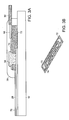
- the apparatus 10 for measuring a mammalian subject's cardiac output shown in FIG. 1 contains tube 12 having proximal portion 14 and distal portion 16.
- the tube 12 is generally formed of a medically approved synthetic polymeric material such as silicone rubber, polyvinyl chloride or polypropylene. See, U.S. Patents 3,599,642 and 4,593,690 .
- the distal portion 16 is inserted into the subject during the intubation, and generally has a beveled end with a smooth, curved tip 18 to facilitate insertion.
- the proximal portion 14 of the tube contains a coupler member 20 that is suited to be connected to medical equipment such as a ventilator.
- an inflatable cuff 22 Connected to the distal portion 16 is an inflatable cuff 22 that, when inflated, causes occlusion of the airway surrounding the apparatus 10, thereby fixing the tube in correct position while allowing the ventilator to completely regulate the patient's respiration.
- the inflatable cuff 22 is fully deflated when it is inserted into the subject's airway in order to reduce the risk of injury to the subject during intubation. Inflation and deflation of the cuff 22 are controlled through a small secondary tubule 24 that is inserted at the proximal end of the tube.
- the apparatus 10 also includes several electrodes 25 operably joined to the distal portion of the tube and the inflatable cuff.
- the electrode contains two principal features: an electrode patch 26 that is generally rectangular and is disposed on the outer surface of the inflatable cuff, and an electrode runner 28 that extends in a proximal-distal orientation between the electrode patch and the point where the electrode runners terminate and are attached to a bundle or sheath of external wires 30.
- the collection of external wires 30 is also termed a flexible circuit or flex circuit.
- the electrode runners terminate near the middle of the tube in a proximal-distal orientation.
- the electrode patch 26 has a rectangular ( e .
- the electrode patch 26 is connected to the electrode runner 28 at a corner or side of the electrode patch 26.
- the electrode patch can include a triangularly-shaped conductive material 32 that interfaces with the electrode patch 26 and electrode runner 28.
- the electrode runners 28 and the external wires 30 are connected using a conductive compound.
- An exemplary embodiment of the connection between the electrode runners 28 and the external wires 30 is schematically depicted in FIGS. 3A and 3B .
- the external wires 30 terminate at an end 68 not surrounded by any insulating sheath, but is connected to a traced conductive circuit material 70 operably linked to a flexible support material 72.
- the flexible support material 72 is any suitable material having the properties of being thin and flexible, such as a polyimide or polyamide material ( e . g ., a Kapton® polyimide film by DuPont).
- the traced conductive circuit material 70 and the flexible support material 72 contain a series of holes 74 .
- the traced conductive circuit material 70 and the flexible support material 72 are applied over the termini of the electrode runners 28 , such that the holes 74 align with the proximal end of each electrode runner 28 .
- a conductive polymeric material 34 (such as Conductive Compounds® EP-600 epoxy resin, Londonderry, NH) is applied so as to fill or partially fill holes 74 and thereby form an electrical connection between electrode runner 28 and external wires 30 .
- the conductive polymeric material 34 is cured, such as by placing the apparatus in a container heated to a temperature of about 110°C for a period of time from about ten minutes to about two hours.
- Insulating material 78 is applied over the connection between the electrode runner 28 and the external wires 30 .
- Insulating material 78 is a sealing tape, a molded sealing collar or any medically-acceptable polymeric material, such as a two-stage medical epoxy (e . g ., Loctite® M-121HP epoxy, Henkel Corporation) that protects the electrodes from bodily fluids and thereby increases the durability of the device.
- a two-stage medical epoxy e . g ., Loctite® M-121HP epoxy, Henkel Corporation
- the spacing between the ends of the electrode runners 28 to which the external wires 30 are connected is a consideration. It is generally preferable to have a space of at least about one millimeter between adjacent ends of the electrode runners 28. This spacing prevents the build-up of any capacitance between adjacent ends. Also, this spacing also reduces the risk of a high potential electrical failure.
- a plurality of electrodes is disposed on the inflatable cuff 22.
- the placement of the electrode patches 26 is dictated to some extent by the opportunity to maximize the detection and measurement of voltages caused by the current flowing in the tissue.
- An exemplary placement of multiple electrode patches 26 on the outer surface of the inflated cuff is shown in FIG. 2 .
- there is a plurality of sense electrodes that includes at least two sense electrodes, and preferably includes three, four or five sense electrodes. The combination of five sense electrodes provides three orthogonal pairs of sense electrodes.
- the portion of the electrode runner 28 on the region of the inflatable cuff 22 that does not contact the tube is fabricated such that it forms a beam-like structure 36.
- the electrode runners on the inflatable cuff remain substantially linear and rigid when the inflatable cuff is 22 deflated.
- These beam-like structures 36 are important to the functionality of the apparatus 10 when it is inserted into a subject because they increase electrode durability and facilitate deflation of the inflatable cuff 22.
- the pressure on the inflated cuff 22 rhythmically increases and is then relaxed.
- the beam-like structures 36 do not appreciably change shape during this cycle, but there is substantial change in the shape of the portions of the inflatable cuff between the beam-like structures 36 , which decreases the force on the beam-like structures 36 and increases durability of the electrodes.
- the regions of the electrode runners 28 that are positioned on the inflatable cuff 22 are arranged in an array so as to increase the ability of the cuff 22 to collapse when deflated, such that the electrode patches and beam-like structures 36 lay roughly flat against the portion of the tube underlying the inflatable cuff 22.
- multiple beam-like structures 36 extend from the point where the proximal end of the inflatable cuff 38 contacts the tube to the electrode patch.
- the electrode runners 28 are placed generally parallel to adjoining electrode runners along the distal portion of the tube.
- the width of the electrode runner 28 can by adjusted.
- the width of the electrode runner 28 can range from about 0.1 millimeters to about two millimeters; in a preferred embodiment, the electrode runners 28 are about one millimeter in width along the distal portion of the tube 12 .
- the electrode runners 28 diverge from adjoining electrode runners 28 at a point on the tube proximal to the inflatable cuff 22 ; in other words, the distance between adjacent runners 28 is generally uniform along the length of the distal 16 portion of the tube 12 , but increases as the electrode runners 28 near the inflatable cuff 22 .
- the electrode runners 28 extend generally linearly along the surface of the inflatable cuff 22 to form beam-like structures 36 and separate from adjacent beam-like structures 36 .
- This separation increases as the electrode runners 28 approach the electrode patches 26 , which are in proximity to the point of the inflatable cuff 22 at which the maximal circumference 40 is obtained.
- the result of this separation is that the circumferential distance between adjacent beam-like structures 36 is greater at the region of the inflated inflatable cuff wherein maximal outer diameter 40 of the cuff 22 is achieved than at the region where the inflatable cuff 22 contacts the distal portion of the tube 38 .
- This separation increases the ability of the electrode patches 26 and beam-like structures 36 to fold flat against the tube 12 during deflation of the inflatable cuff 22.
- the apparatus 10 also includes a current electrode 42.
- the current electrode 42 has an electrode patch 44 of generally rectangular shape that is positioned between the distal end 18 of the tube and the midpoint 46 of the apparatus. Preferably, the current electrode 42 is located on the outer radius of the curve formed by the tube. This orientation provides for better contact between the current electrode 42 and the subject's trachea.
- the current electrode 42 is of an area sufficient to function as a current electrode.
- the electrode patch 44 of the current electrode 42 is at least 28 millimeters in length as measured in a proximal-distal orientation.
- the current electrode 42 also includes an electrode runner 48 extending distally from the flex circuit 30 of the apparatus to the electrode patch 44 of the current electrode 42.
- the current electrode extends over about 90°, 120°, or about 180° of the circumference of the tube.
- the current electrode runner 48 is fabricated from a conductive material, and is separated from the tube by a polymeric underlayer that is applied to the tube prior to application of the conductive material.
- the electrode patch of the current electrode 44 may be separated from the tube by the polymeric underlayer.
- the current electrode runner 48 is covered by a polymeric overlayer applied to the conductive material.
- the cuff 22 When fully inflated, the cuff 22 is of sufficient size to fix the position of the endotracheal tube such that there is not substantial movement either downward or upward relative to the subject's trachea.
- the cuff 22 has a maximal outer diameter of at least twenty millimeters.
- the apparatus also includes a tubule 24 for inflating the inflatable cuff 22.
- the tubule 24 has a proximal 50 and distal end 52, the distal end 52 extending from the cuff 22 in the internal space of the distal portion 16 of the tube and exiting the tube 12 in the proximal portion near the midline 46.
- the proximal end 50 of the tubule has an inlet 54 for air or another gas under pressure for inflating the cuff 22.
- valve housing At the proximal end 50 of the tubule 24 is a valve housing provided with an air inlet bore 56 and valve means 58 in the bore 56 such that the inlet is 54 normally closed, but air is admitted under pressure through the inlet bore 56 to inflate the cuff 22.
- the apparatus 10 is operably connected to a bioelectrical impedance recorder, where the impedance recorder is electrically coupled to the sense electrodes.
- Bioelectrical impedance analysis of blood flow using electrode sensors arrayed within or external to the trachea is well known in the art. See, e.g., U.S. Patents 5,791,349 and 6,095,987 .
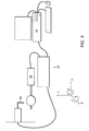
- the present disclosure provides an apparatus 10 arrayed with electrodes 25 disposed on an inflatable cuff 22. These electrodes 25 are applied to the tubes 12 using a novel printing methodology that uses a positive displacement dispensing system 60. While this methodology is specifically described herein as useful for applying materials onto the surface of the apparatus 10 and the associated inflatable cuff 22, one of skill in the art will recognize that the printing methods described herein are also useful for applying a material to any non-repeatably formed substrate (e.g., a dilation balloon used in a medical device).
- the printing methodology generally involves two steps: imaging the non-repeatably formed substrate and applying one or more materials thereon.
- the application step can be termed "writing", “printing” or any other equivalent term known to those skilled in the art. These two general steps are discussed in turn.
- the inflatable cuff 22 is at least partially inflated prior to printing the electrodes 25 on its outer surface. Due to inherent variations in the three dimensionality of the inflated cuff 22 one must have an understanding of the shape of the inflated cuff 22 prior to positioning the electrodes 25. For this reason, the inflated cuff is 22 imaged by capturing either video or still images. In certain embodiments video images of the inflated cuff 22 and the adjacent regions of the distal region 16 of the tube are collected and sent to a processing system, such as a computer 62 that generates a map showing the contours of the inflated cuff 22. In other embodiments, one or more still images are captured and reproduced (such as by digital printing) in order to generate the contour image map. Generally three or more still images are captured to generate the contour image map. In preferred embodiments, eight images are captured.
- the displacement dispensing system contains a writing head 64 (such as a pen tip) and a substrate stage 66 capable of moving the substrate in at least three independent dimensions.
- the writing head is 64 capable of movement relative to the substrate stage 66.
- the writing head 64 applies to the substrate any liquid or semi-solid materials, including the polymeric underlayer and overlayers, and the conductive material used to form the electrodes 25.
- FIG. 4 An exemplary positive displacement dispensing system 60 is shown in FIG. 4 .
- a writing head 64 is mounted on an axis capable of moving in one dimension only, shown in FIG. 4 as the y-axis.
- the substrate stage 66 is capable of moving in at least three independent dimensions, shown in FIG. 4 as the x-axis, ⁇ (clockwise or counter-clockwise rotation along the z- axis, and ⁇ (clockwise or counter-clockwise rotation along the x-axis).
- the substrate stage 66 is capable of moving in a fourth independent direction, shown in FIG. 4 as the y-axis.
- the positive displacement dispensing system 60 is used to print the electrodes 25 in a sandwich format: the conductive material is surrounded by the polymeric underlayer on the bottom (i.e., the area closest to the tube) and the polymeric overlayer on the top (i.e., the area furthest from the tube), except for a portion of the electrode patch 26 , which is not covered by the polymeric overlayer and therefore is able to directly contact the tracheal mucosa when inserted into a subject's trachea, and the end of the electrode runner 28 that contacts the external wires 30 .
- the writing head 64 applies to a region of the inflated cuff 22 a polymeric underlayer.
- the region to which the polymeric underlayer is applied is based upon the imaging data obtained from the contour map described above.
- the writing head 64 writes a thin, narrow layer of material directly on the distal portion of the tube 16 and extending to the inflatable cuff 22 , which is at least partially inflated.
- the inflatable cuff 22 is inflated to an inflation pressure of about 10 to about 40 cm H 2 O, e . g ., about 25 cm H 2 O. Because the course of the writing head 64 is controlled based on information regarding the contours of the inflated cuff 22 and the distal portion 16 of the tube, multiple parallel lines can be formed along the proximal-distal axis of the tube 12.
- materials useful as polymeric underlayer include an ultraviolet (UV)-curable resin such as Dymax® 1-20323 resin and Creative Materials dielectric inks (e.g., CMI-115-30).
- UV ultraviolet
- the tube 12 and cuff 22 may be cleaned with a solvent such as ethanol or with physical means (such as an ionizing gun) to remove debris.
- the underlayer is optionally cured, such as by exposure to UV or visible light radiation or a similar curing agent.
- Wrinkles or other deformations may exist in the cuff 22 prior to printing.
- the tube 12 prior to printing the underlayer the tube 12 may be heated, such as at 30-100°C (e.g., about 60°C) for a period of time (e.g., 1-60 minutes, preferably about 45 minutes) after inflation of the cuff 22 to remove any wrinkles present in the tube 12 or the inflatable cuff 22 .
- a physical force can be applied to the cuff 22 to remove any wrinkles prior to printing.
- the shape of the inflatable cuff 22 can be modified prior to electrode printing.
- a vacuum can be applied to the end of the cuff 22 closest to the distal tip 18 of the apparatus, resulting in a deformation of the cuff 22 ; this deformation preferably results in a decrease in the angle formed by the inflatable cuff 22 as it extends away from the proximal end of the tube, such that printing on the cuff becomes easier.
- physical force can be applied to the proximal end of the cuff 22 by contacting one or more regions of the cuff with projections, or "fingers", that pull the cuff in a distal direction along a proximal-distal axis.
- the printing of the electrode patches 26 and electrode runners 28 is performed by applying the writing head 64 with the portions of the inflatable cuff 22 not contacted or otherwise obscured by the projections.
- the application of physical force reduces or eliminates any wrinkles in the inflatable cuff 22 and transforms the inflatable cuff 22 into a defined writing surface, thereby obviating the need to image the inflated cuff 22 prior to the writing step.
- the dispensing system 60 Upon completion of the printing of the polymeric underlayer, the dispensing system 60 has a functional "road map" for where to place the conductive material that is used to form the electrode runners 28 and electrode patches 26. Generally, the width of the line formed by the conductive material will be less than that of the polymeric underlayer, such that no conductive material directly contacts either the distal portion of the tube 16 or the inflatable cuff 22.
- materials useful as a conductive material include electrically conductive inks such as CMI 101-59 (Creative Materials Inc., Tyngsboro, MA) or any other electrically conductive particles such as silver or gold particles that are suspended in a resin and a solvent. After printing the conductive material on the tube 12 is optionally cured, such as by heating the tube.
- This curing step results in the formation of a polymeric matrix surrounding the conductive particles.
- the tube 12 is placed in a suitable container, which is then heated to a temperature of 90-150°C (e.g., 120°C) for a period of time (e.g., 30 minutes to five hours or more).
- the temperature of the container may be gradually increased, such as increasing the temperature by 0.1 -5°C per minute.
- a polymeric overlayer 76 is written over the conductive material the length of the electrode runner 28 , which is acceptable because no signals are directly measured from the electrode runner 28 itself.
- the overlayer is written over the outer periphery of the electrode patch 26 on the inflated cuff 22 .
- the outer one millimeter of each side of the electrode patch 26 is covered with the polymeric overlayer.
- the purpose of this overlayer is to increase durability of the electrodes 25 and prevent errors in signal processing.
- the overlayer extends from the periphery of the electrode patch 26 over the polymeric underlayer and onto the surrounding material of the inflatable cuff 22 .
- the overlayer extends beyond the periphery of the electrode patch 26 but does not extend beyond the polymeric underlayer. This extension results in a seal that strengthens the attachment of the electrode patch 26 to the inflatable cuff 22 , thereby decreasing the probability that physical strain on the electrode patch 26 will cause its separation from the inflatable cuff 22 .
- materials useful as polymeric overlayers include an ultraviolet (UV)-curable resin such as Dymax® 1-20323 resin, or Creative Materials dielectric ink (e.g., CMI-115- 30).
- UV ultraviolet
- the tube 12 may be cleaned with a solvent such as ethanol or with physical means (such as an ionizing gun) to remove debris.
- the apparatus 10 is optionally cured, such as by exposure to UV or visible light radiation or a similar curing agent.
- Endotracheal tubes bearing electrodes have been previously described as useful for measuring cardiac function, including cardiac output. See U.S. Patents 6,095,987 and 6,292,689 .
- the endotracheal tubes as described herein are useful to measure physiological functions in mammalian subjects. For example, cardiac output is measured, and any pathological situation identified, using the electrodes arrayed on the inflatable cuff.
- the disclosure provides a method of measuring the cardiac output of a mammalian subject by providing an endotracheal tube substantially as described herein.
- the endotracheal tube includes a current electrode connected thereto and an inflatable cuff containing an array of electrodes including a plurality of sense electrodes and a ground electrode, and is positioned in the trachea in the vicinity of the aorta so that inflating the cuff results in the cuff contacts the tracheal mucosa.
- the tube is adapted to be inserted in the trachea of the subject through the mouth, a nasal passageway, or a tracheotomy port.
Landscapes
- Health & Medical Sciences (AREA)
- Life Sciences & Earth Sciences (AREA)
- Engineering & Computer Science (AREA)
- Medical Informatics (AREA)
- Surgery (AREA)
- Biophysics (AREA)
- Pathology (AREA)
- Veterinary Medicine (AREA)
- Biomedical Technology (AREA)
- Heart & Thoracic Surgery (AREA)
- Public Health (AREA)
- Molecular Biology (AREA)
- Physics & Mathematics (AREA)
- Animal Behavior & Ethology (AREA)
- General Health & Medical Sciences (AREA)
- Hematology (AREA)
- Cardiology (AREA)
- Nuclear Medicine, Radiotherapy & Molecular Imaging (AREA)
- Radiology & Medical Imaging (AREA)
- Physiology (AREA)
- Microelectronics & Electronic Packaging (AREA)
- Measurement And Recording Of Electrical Phenomena And Electrical Characteristics Of The Living Body (AREA)
- Measuring Pulse, Heart Rate, Blood Pressure Or Blood Flow (AREA)
Description
- The invention provides an apparatus for measuring cardiac output in a mammalian subject. The apparatus includes a tube and an inflatable cuff and is configured so that electrodes on the inflatable cuff located in close proximity to the subject's aorta measure voltage changes following stimulation of the tissue with a current delivered by an electrode. The electrodes are printed on the tube and the cuff with a positive displacement dispensing system to improve the durability of the apparatus.
- Cardiac output is a calculation of the volume of blood being pumped by the heart, for example a ventricle, per minute. Cardiac output is equivalent to the heart rate multiplied by the stroke volume. Understanding of a subject's cardiac output is important in care of acutely injured or ill subjects, as well as individuals with chronic cardiac pathology. Until recently the standard of cardiac output measurement has been pulmonary artery catheterization. See, e.g.,
U.S. Patents 3,915,155 ;3,726,269 and3,651,318 . - Bioelectrical impedance analysis ("BIA") has been developed to measure physiological and pathological properties, including cardiac output. In performing BIA, a low level electrical alternating current is introduced into a tissue being monitored electrically by multiple electrodes, such that the voltage difference between multiple locations on the tissue is determined. From this determination, the electrical impedance (electrical resistance plus reactance) of the stimulated tissue is calculated. Previously, both external (
U.S. Patent 4,870,578 ) and internal (U.S. Patents 4,852,580 and4,836,214 ) electrodes have been employed to measure electrical resistance representing blood flow in the aorta. While these internal electrodes were mounted on esophageal catheters, it was later determined that endotracheal tubes could be adapted by the addition of electrodes on the inflatable cuff, which was perceived to be a more accurate measurement of cardiac output. SeeU.S. Patents 6,095,987 and6,292,689 . - The process of inserting an endotracheal tube is called intubation, and is performed\\\ when the inflatable cuff is deflated. The presence of electrodes on the inflatable cuff and electrode leads on the external surface of the endotracheal tube results in a more complex and riskier intubation process. Further, the electrodes are attached to the inflatable cuff when inflated, resulting in irregularities (e.g., sharp edges of the electrode, broken electrode leads) when the cuff is deflated prior to insertion.
- In view of the foregoing, it would be desirable to provide an apparatus and methods for safely, accurately, efficiently and continuously determining cardiac output by measuring electrical impedance.
US 6,292,689 teaches an apparatus according to the preamble of claim 1 and a method for monitoring cardiac output using bioelectrical impedance techniques in which three orthogonal pairs of sense electrodes are placed in the trachea or esophagus in the vicinity of the aorta, while an excitation current is injected into the intervening tissue mass via a current electrode, so that bioelectrical impedance measurements based on the voltage drop sensed by the sense electroeds reflect voltage changes induced primarily by blood flow dynamics. The sense, current, and shaft electrodes are composed of a conductive silver ink screened onto a polyethylene backing.
The article of PIEPER CF, LAWRIE G, PARSONS D, LACY J, ROBERTS R, AND PACIFICO A entitled "Experience with Kapton-based bipolar electrode arrays used during computerized intraoperative mapping" and published in J CARDIOVASC ELECTROPHYSIOL, vol. 1, December 1990, page 496-505, discloses a Kapton-based bipolar electrode for attachment to a cardiac mapping balloon catheter and particularly a Kapton-copper-Kapton-copper-Kapton structure where layers of copper are electroplated to both sides of a Kapton sheet, electrodes are formed from the copper layers by lithographic etching, and two additional bare Kapton sheets, predrilled to expose the electrodes, are bonded to opposite sides of the etched stock. - In general, the present disclosure relates to detection of cardiac output, and diseases characterized by abnormal cardiac function, using a novel apparatus that is placed in such a manner that a portion of the apparatus contacts the tracheal tissue in close proximity to the aorta. The present invention is defined by the independent claims.
- A medical device according to the present invention, comprising an endotracheal tube, is defined in independent claim 1.
- The sense electrodes and the ground electrode are separated from the inflatable cuff by a polymeric underlayer that is applied to the inflatable cuff and the tube prior to application of the sense electrodes and the ground electrode. The apparatus according to the present invention also includes a polymeric overlayer. In certain embodiments the polymeric underlayer contains a medical grade adhesive, such as a urethane oligomer/acrylate monomer blend (e.g., Dymax® 1-20323 resin, Torrington, CT) the electrode contains electrically conductive silver particles suspended in a resin and a volatile solvent that forms a polymeric matrix material once cured (such as Creative Materials - CMI 101-59), or the polymeric overlayer contains a medical grade adhesive, such as a urethane oligomer/acrylate monomer blend (e.g., Dymax® 1-20323 resin).
- The medical device includes a plurality of sense electrodes, and may be three, four, five or more than five sense electrodes. For example, the combination of the five sense electrodes provides three orthogonal pairs of sense electrodes. Also, the current electrode is disposed on the distal portion of the tube between the termini of the electrode runners (near the middle of the tube in a proximal-distal direction) and the inflatable cuff. In certain embodiments, the current electrode is at least one centimeter in length (e.g., one, two or more centimeters) as measured in the proximal-distal dimension of the tube. In some embodiments the current electrode extends over about 90°, 120°, or about 180° of the circumference of the tube.
- It is also provided a method of fabricating a medical device according to one of claims 1-7 as defined in independent claim 8. No polymeric overlayer is applied to a plurality of regions of the conductive material, thereby forming a plurality of electrode patches. The imaging step comprises capturing images, such as dynamic video images. The imaging step includes in certain embodiments the capturing of a plurality of images that are used to identify one or more contours of the second portion.
- One or more of the polymeric underlayer, the conductive material, or the polymeric overlayer are applied by a positive displacement dispensing system. The positive displacement dispensing system includes a pen tip that is kept substantially perpendicular to the surface of the second portion during application of the polymeric underlayer, the conductive material, or the polymeric overlayer.
- In some embodiments, the apparatus is mounted on a stage having at least three independent axes of motion relative to the pen tip. For example, the apparatus is mounted on a stage having at least four independent axes of motion relative to the pen tip: motion along a direction perpendicular to the pen tip, motion along a direction towards or away from the pen tip, rotational motion along an axis perpendicular to the pen tip, and rotational motion along an axis parallel to the pen tip. In other embodiments, the positive displacement dispensing system includes a MicroPen® (MicroPen Technologies Honeoye Falls, NY).
- In some embodiments, the positive displacement dispensing system comprises a MicroPen®.
- It is also disclosed a non-claimed apparatus produced by a process containing the steps of providing a tube having a proximal portion and a distal portion, and an inflatable cuff disposed on the distal portion of the tube, at least partially inflating the cuff, imaging the inflated cuff so as to obtain imaging data, directing a positive displacement dispensing system to apply to a region of the inflated cuff a polymeric underlayer based upon the imaging data, applying to at least a portion of the polymeric underlayer a conductive material to form a plurality of electrodes based upon the imaging data, and applying to a portion of the conductive material a polymeric overlayer based upon the imaging data, and where no polymeric overlayer is applied to a plurality of regions of the conductive material so as to form a plurality of electrode patches.
- It is also disclosed a non-claimed method of applying a material to a non-repeatably formed substrate by providing a positive displacement dispensing system containing a pen tip, mounting the substrate on a stage having four independent axes of motion relative to the pen tip, imaging the substrate by capturing still or video images so as to obtain imaging data, and directing the positive displacement dispensing system to apply to at least a region of the substrate a material based upon the imaging data. The independent axes of motion include motion along a direction perpendicular to the pen tip, motion along a direction towards or away from the pen tip, rotational motion along an axis perpendicular to the pen tip, and rotational motion along an axis parallel to the pen tip.
- In certain aspects, the imaging data are processed so as to generate a three-dimensional representation of the substrate, and the pen tip is kept at an angle substantially perpendicular to the region of the substrate to which the material is being applied. Unless otherwise defined, all technical and scientific terms used herein have the same meaning as commonly understood by one of ordinary skill in the art to which this invention belongs. Although methods and materials similar or equivalent to those described herein can be used in the practice or testing of aspects of the present invention, suitable methods and materials are described below. The materials, methods, and examples are illustrative only.
- The present invention may be further appreciated with reference to the appended drawing sheets wherein:
-
FIG. 1 is a schematic illustration demonstrating one embodiment of the endotracheal tube of the present invention; -
FIG. 2 is a partial sectional illustration of the endotracheal tube of the present invention. -
FIG. 3 is a partial sectional illustration of an electrical assembly of the present invention. -
FIG. 4 is a schematic illustration of a positive displacement dispensing system used in the present invention. - Other objects, features, and advantages of the present invention will become apparent from the following detailed description. It should be understood, however, that the detailed description and the specific examples, while indicating preferred embodiments,
are given by way of illustration only, since various changes and modifications will become apparent to those skilled in the art from this detailed description. - In some embodiments described herein, the present disclosure relates generally to an apparatus useful as an endotracheal tube (also known as an intratracheal tube or ET tube). The endotracheal tube is useful in measuring physiological characteristics of a mammalian subject, particularly human subjects suffering from acute or chronic injury or illness. For example, the endotracheal tube is used to measure cardiac output in a mammalian subject. The endotracheal tube is inserted into the trachea, generally via the mouth, but sometimes through the nares of the nose or even through a tracheostomy.
- The apparatus 10 for measuring a mammalian subject's cardiac output shown in
FIG. 1 containstube 12 havingproximal portion 14 anddistal portion 16. Thetube 12 is generally formed of a medically approved synthetic polymeric material such as silicone rubber, polyvinyl chloride or polypropylene. See,U.S. Patents 3,599,642 and4,593,690 . Thedistal portion 16 is inserted into the subject during the intubation, and generally has a beveled end with a smooth,curved tip 18 to facilitate insertion. Theproximal portion 14 of the tube contains acoupler member 20 that is suited to be connected to medical equipment such as a ventilator. Connected to thedistal portion 16 is aninflatable cuff 22 that, when inflated, causes occlusion of the airway surrounding the apparatus 10, thereby fixing the tube in correct position while allowing the ventilator to completely regulate the patient's respiration. Generally theinflatable cuff 22 is fully deflated when it is inserted into the subject's airway in order to reduce the risk of injury to the subject during intubation. Inflation and deflation of thecuff 22 are controlled through a smallsecondary tubule 24 that is inserted at the proximal end of the tube. - The apparatus 10 also includes several electrodes 25 operably joined to the distal portion of the tube and the inflatable cuff. The electrode contains two principal features: an
electrode patch 26 that is generally rectangular and is disposed on the outer surface of the inflatable cuff, and anelectrode runner 28 that extends in a proximal-distal orientation between the electrode patch and the point where the electrode runners terminate and are attached to a bundle or sheath ofexternal wires 30. The collection ofexternal wires 30 is also termed a flexible circuit or flex
circuit. Generally the electrode runners terminate near the middle of the tube in a proximal-distal orientation. In certain embodiments theelectrode patch 26 has a rectangular (e.g., square) shape, but it should be recognized that the present invention provides for any shape of electrode patch that can be fabricated using the methods described herein and the teachings of the art (e.g., circle, oval, or any polyhedra such as triangle, pentagon, hexagon, heptagon, or octagon). Theelectrode patch 26 is connected to theelectrode runner 28 at a corner or side of theelectrode patch 26. The electrode patch can include a triangularly-shapedconductive material 32 that interfaces with theelectrode patch 26 andelectrode runner 28. - In certain embodiments of the invention the
electrode runners 28 and theexternal wires 30 are connected using a conductive compound. An exemplary embodiment of the connection between theelectrode runners 28 and theexternal wires 30 is schematically depicted inFIGS. 3A and 3B . Theexternal wires 30 terminate at anend 68 not surrounded by any insulating sheath, but is connected to a tracedconductive circuit material 70 operably linked to aflexible support material 72. Theflexible support material 72 is any suitable material having the properties of being thin and flexible, such as a polyimide or polyamide material (e.g., a Kapton® polyimide film by DuPont). The tracedconductive circuit material 70 and theflexible support material 72 contain a series ofholes 74. After theelectrode runners 28 are printed on thetube 12 the tracedconductive circuit material 70 and theflexible support material 72 are applied over the termini of theelectrode runners 28, such that theholes 74 align with the proximal end of eachelectrode runner 28. A conductive polymeric material 34 (such as Conductive Compounds® EP-600 epoxy resin, Londonderry, NH) is applied so as to fill or partially fillholes 74 and thereby form an electrical connection betweenelectrode runner 28 andexternal wires 30. Optionally, the conductivepolymeric material 34 is cured, such as by placing the apparatus in a container heated to a temperature of about 110°C for a period of time from about ten minutes to about two hours. An insulatingmaterial 78 is applied over the connection between theelectrode runner 28 and theexternal wires 30. Insulatingmaterial 78 is a sealing tape, a molded sealing collar or any medically-acceptable polymeric material, such as a two-stage medical epoxy (e.g., Loctite® M-121HP epoxy, Henkel Corporation) that protects the electrodes from bodily fluids and thereby increases the durability of the device. - The spacing between the ends of the
electrode runners 28 to which theexternal wires 30 are connected is a consideration. It is generally preferable to have a space of at least about one millimeter between adjacent ends of theelectrode runners 28. This spacing prevents the build-up of any capacitance between adjacent ends. Also, this spacing also reduces the risk of a high potential electrical failure. - In several embodiments of the invention, a plurality of electrodes is disposed on the
inflatable cuff 22. The placement of theelectrode patches 26 is dictated to some extent by the opportunity to maximize the detection and measurement of voltages caused by the current flowing in the tissue. An exemplary placement ofmultiple electrode patches 26 on the outer surface of the inflated cuff is shown inFIG. 2 . In certain embodiments, there is a plurality of sense electrodes that includes at least two sense electrodes, and preferably includes three, four or five sense electrodes. The combination of five sense electrodes provides three orthogonal pairs of sense electrodes. - The portion of the
electrode runner 28 on the region of theinflatable cuff 22 that does not contact the tube is fabricated such that it forms a beam-like structure 36. By this is meant that the electrode runners on the inflatable cuff remain substantially linear and rigid when the inflatable cuff is 22 deflated. These beam-like structures 36 are important to the functionality of the apparatus 10 when it is inserted into a subject because they increase electrode durability and facilitate deflation of theinflatable cuff 22. When thedistal portion 16 of the tube is placed in a subject's trachea and theinflatable cuff 22 is inflated to secure the apparatus in position, theelectrode patches 26 come into tight contact with the subject's tracheal walls. During the breathing cycle, the pressure on theinflated cuff 22 rhythmically increases and is then relaxed. The beam-like structures 36 do not appreciably change shape during this cycle, but there is substantial change in the shape of the portions of the inflatable cuff between the beam-like structures 36, which decreases the force on the beam-like structures 36 and increases durability of the electrodes. - The regions of the
electrode runners 28 that are positioned on theinflatable cuff 22 are arranged in an array so as to increase the ability of thecuff 22 to collapse when deflated, such that the electrode patches and beam-like structures 36 lay roughly flat against the portion of the tube underlying theinflatable cuff 22. In certain embodiments, multiple beam-like structures 36 extend from the point where the proximal end of theinflatable cuff 38 contacts the tube to the electrode patch. - The
electrode runners 28 are placed generally parallel to adjoining electrode runners along the distal portion of the tube. The width of theelectrode runner 28 can by adjusted. For example, the width of theelectrode runner 28 can range from about 0.1 millimeters to about two millimeters; in a preferred embodiment, theelectrode runners 28 are about one millimeter in width along the distal portion of thetube 12. Theelectrode runners 28 diverge from adjoiningelectrode runners 28 at a point on the tube proximal to theinflatable cuff 22; in other words, the distance betweenadjacent runners 28 is generally uniform along the length of the distal 16 portion of thetube 12, but increases as theelectrode runners 28 near theinflatable cuff 22. Theelectrode runners 28 extend generally linearly along the surface of theinflatable cuff 22 to form beam-like structures 36 and separate from adjacent beam-like structures 36. This separation increases as theelectrode runners 28 approach theelectrode patches 26, which are in proximity to the point of theinflatable cuff 22 at which themaximal circumference 40 is obtained. The result of this separation is that the circumferential distance between adjacent beam-like structures 36 is greater at the region of the inflated inflatable cuff wherein maximalouter diameter 40 of thecuff 22 is achieved than at the region where theinflatable cuff 22 contacts the distal portion of thetube 38. This separation increases the ability of theelectrode patches 26 and beam-like structures 36 to fold flat against thetube 12 during deflation of theinflatable cuff 22. - The apparatus 10 also includes a
current electrode 42. Thecurrent electrode 42 has anelectrode patch 44 of generally rectangular shape that is positioned between thedistal end 18 of the tube and the midpoint 46 of the apparatus. Preferably, thecurrent electrode 42 is located on the outer radius of the curve formed by the tube. This orientation provides for better contact between thecurrent electrode 42 and the subject's trachea. Thecurrent electrode 42 is of an area sufficient to function as a current electrode. For example, theelectrode patch 44 of thecurrent electrode 42 is at least 28 millimeters in length as measured in a proximal-distal orientation. Thecurrent electrode 42 also includes an electrode runner 48 extending distally from theflex circuit 30 of the apparatus to theelectrode patch 44 of thecurrent electrode 42. In some embodiments the current electrode extends over about 90°, 120°, or about 180° of the circumference of the tube. As described herein, the current electrode runner 48 is fabricated from a conductive material, and is separated from the tube by a polymeric underlayer that is applied to the tube prior to application of the conductive material. The electrode patch of thecurrent electrode 44 may be separated from the tube by the polymeric underlayer. Furthermore, the current electrode runner 48 is covered by a polymeric overlayer applied to the conductive material. - When fully inflated, the
cuff 22 is of sufficient size to fix the position of the endotracheal tube such that there is not substantial movement either downward or upward relative to the subject's trachea. For example, thecuff 22 has a maximal outer diameter of at least twenty millimeters. - In certain embodiments the apparatus also includes a
tubule 24 for inflating theinflatable cuff 22. For example, thetubule 24 has a proximal 50 anddistal end 52, thedistal end 52 extending from thecuff 22 in the internal space of thedistal portion 16 of the tube and exiting thetube 12 in the proximal portion near the midline 46. Theproximal end 50 of the tubule has aninlet 54 for air or another gas under pressure for inflating thecuff 22. At theproximal end 50 of thetubule 24 is a valve housing provided with an air inlet bore 56 and valve means 58 in thebore 56 such that the inlet is 54 normally closed, but air is admitted under pressure through the inlet bore 56 to inflate thecuff 22. - In certain embodiments, the apparatus 10 is operably connected to a bioelectrical impedance recorder, where the impedance recorder is electrically coupled to the sense electrodes. Bioelectrical impedance analysis of blood flow using electrode sensors arrayed within or external to the trachea is well known in the art. See, e.g.,
U.S. Patents 5,791,349 and6,095,987 . - In certain embodiments the present disclosure provides an apparatus 10 arrayed with electrodes 25 disposed on an
inflatable cuff 22. These electrodes 25 are applied to thetubes 12 using a novel printing methodology that uses a positivedisplacement dispensing system 60. While this methodology is specifically described herein as useful for applying materials onto the surface of the apparatus 10 and the associatedinflatable cuff 22, one of skill in the art will recognize that the printing methods described herein are also useful for applying a material to any non-repeatably formed substrate (e.g., a dilation balloon used in a medical device). - The printing methodology generally involves two steps: imaging the non-repeatably formed substrate and applying one or more materials thereon. The application step can be termed "writing", "printing" or any other equivalent term known to those skilled in the art. These two general steps are discussed in turn.
- The
inflatable cuff 22 is at least partially inflated prior to printing the electrodes 25 on its
outer surface. Due to inherent variations in the three dimensionality of theinflated cuff 22 one must have an understanding of the shape of theinflated cuff 22 prior to positioning the electrodes 25. For this reason, the inflated cuff is 22 imaged by capturing either video or still images. In certain embodiments video images of theinflated cuff 22 and the adjacent regions of thedistal region 16 of the tube are collected and sent to a processing system, such as acomputer 62 that generates a map showing the contours of theinflated cuff 22. In other embodiments, one or more still images are captured and reproduced (such as by digital printing) in order to generate the contour image map. Generally three or more still images are captured to generate the contour image map. In preferred embodiments, eight images are captured. - Information from the contour map obtained above is provided to a positive
displacement dispensing system 60 capable of responding to the contour map by altering one or more printing dimensions. The displacement dispensing system contains a writing head 64 (such as a pen tip) and asubstrate stage 66 capable of moving the substrate in at least three independent dimensions. The writing head is 64 capable of movement relative to thesubstrate stage 66. The writinghead 64 applies to the substrate any liquid or semi-solid materials, including the polymeric underlayer and overlayers, and the conductive material used to form the electrodes 25. - An exemplary positive
displacement dispensing system 60 is shown inFIG. 4 . A writinghead 64 is mounted on an axis capable of moving in one dimension only, shown inFIG. 4 as the y-axis. In contrast, thesubstrate stage 66 is capable of moving in at least three independent dimensions, shown inFIG. 4 as the x-axis, ϕ (clockwise or counter-clockwise rotation along the z- axis, and θ (clockwise or counter-clockwise rotation along the x-axis). In certain embodiments, thesubstrate stage 66 is capable of moving in a fourth independent direction, shown inFIG. 4 as the y-axis. - Preferably, the positive
displacement dispensing system 60 is used to print the electrodes 25 in a sandwich format: the conductive material is surrounded by the polymeric underlayer on the bottom (i.e., the area closest to the tube) and the polymeric overlayer on the top (i.e., the area furthest from the tube), except for a portion of theelectrode patch 26, which is not covered by the polymeric overlayer and therefore is able to directly contact the tracheal mucosa when inserted into a subject's trachea, and the end of theelectrode runner 28 that contacts theexternal wires 30. As such, the writinghead 64 applies to a region of the inflated cuff 22 a polymeric underlayer. The region to which the polymeric underlayer is applied is based upon the imaging data obtained
from the contour map described above. Extending from theflex circuit 30 of the apparatus 10 the writinghead 64 writes a thin, narrow layer of material directly on the distal portion of thetube 16 and extending to theinflatable cuff 22, which is at least partially inflated. For example, theinflatable cuff 22 is inflated to an inflation pressure of about 10 to about 40 cm H2O, e.g., about 25 cm H2O. Because the course of the writinghead 64 is controlled based on information regarding the contours of theinflated cuff 22 and thedistal portion 16 of the tube, multiple parallel lines can be formed along the proximal-distal axis of thetube 12. As used herein, materials useful as polymeric underlayer include an ultraviolet (UV)-curable resin such as Dymax® 1-20323 resin and Creative Materials dielectric inks (e.g., CMI-115-30). Prior to printing the underlayer thetube 12 andcuff 22 may be cleaned with a solvent such as ethanol or with physical means (such as an ionizing gun) to remove debris. After printing, the underlayer is optionally cured, such as by exposure to UV or visible light radiation or a similar curing agent. - Wrinkles or other deformations may exist in the
cuff 22 prior to printing. In certain embodiments, prior to printing the underlayer thetube 12 may be heated, such as at 30-100°C (e.g., about 60°C) for a period of time (e.g., 1-60 minutes, preferably about 45 minutes) after inflation of thecuff 22 to remove any wrinkles present in thetube 12 or theinflatable cuff 22. Alternatively, a physical force can be applied to thecuff 22 to remove any wrinkles prior to printing. - The shape of the
inflatable cuff 22 can be modified prior to electrode printing. For example, a vacuum can be applied to the end of thecuff 22 closest to thedistal tip 18 of the apparatus, resulting in a deformation of thecuff 22; this deformation preferably results in a decrease in the angle formed by theinflatable cuff 22 as it extends away from the proximal end of the tube, such that printing on the cuff becomes easier. - In certain embodiments, physical force can be applied to the proximal end of the
cuff 22 by contacting one or more regions of the cuff with projections, or "fingers", that pull the cuff in a distal direction along a proximal-distal axis. The printing of theelectrode patches 26 andelectrode runners 28 is performed by applying the writinghead 64 with the portions of theinflatable cuff 22 not contacted or otherwise obscured by the projections. The application of physical force reduces or eliminates any wrinkles in theinflatable cuff 22 and transforms theinflatable cuff 22 into a defined writing surface, thereby obviating the need to image the inflatedcuff 22 prior to the writing step. - Upon completion of the printing of the polymeric underlayer, the dispensing
system 60 has a functional "road map" for where to place the conductive material that is used to form theelectrode runners 28 andelectrode patches 26. Generally, the width of the line formed by the conductive material will be less than that of the polymeric underlayer, such that no conductive material directly contacts either the distal portion of thetube 16 or theinflatable cuff 22. As used herein, materials useful as a conductive material include electrically conductive inks such as CMI 101-59 (Creative Materials Inc., Tyngsboro, MA) or any other electrically conductive particles such as silver or gold particles that are suspended in a resin and a solvent. After printing the conductive material on thetube 12 is optionally cured, such as by heating the tube. This curing step results in the formation of a polymeric matrix surrounding the conductive particles. By way of non-limiting example, thetube 12 is placed in a suitable container, which is then heated to a temperature of 90-150°C (e.g., 120°C) for a period of time (e.g., 30 minutes to five hours or more). The temperature of the container may be gradually increased, such as increasing the temperature by 0.1 -5°C per minute. - A
polymeric overlayer 76 is written over the conductive material the length of theelectrode runner 28, which is acceptable because no signals are directly measured from theelectrode runner 28 itself. The overlayer is written over the outer periphery of theelectrode patch 26 on theinflated cuff 22. For example, the outer one millimeter of each side of theelectrode patch 26 is covered with the polymeric overlayer. The purpose of this overlayer is to increase durability of the electrodes 25 and prevent errors in signal processing. Additionally, in one embodiment the overlayer extends from the periphery of theelectrode patch 26 over the polymeric underlayer and onto the surrounding material of theinflatable cuff 22. In another embodiment, the overlayer extends beyond the periphery of theelectrode patch 26 but does not extend beyond the polymeric underlayer. This extension results in a seal that strengthens the attachment of theelectrode patch 26 to theinflatable cuff 22, thereby decreasing the probability that physical strain on theelectrode patch 26 will cause its separation from theinflatable cuff 22. - As used herein, materials useful as polymeric overlayers include an ultraviolet (UV)-curable resin such as Dymax® 1-20323 resin, or Creative Materials dielectric ink (e.g., CMI-115- 30). Prior to printing the overlayer, the
tube 12 may be cleaned with a solvent such as ethanol or with physical means (such as an ionizing gun) to remove debris. After printing the overlayer the apparatus 10 is optionally cured, such as by exposure to UV or visible light radiation or a similar
curing agent. - Endotracheal tubes bearing electrodes have been previously described as useful for measuring cardiac function, including cardiac output. See
U.S. Patents 6,095,987 and6,292,689 . The endotracheal tubes as described herein are useful to measure physiological functions in mammalian subjects. For example, cardiac output is measured, and any pathological situation identified, using the electrodes arrayed on the inflatable cuff. Thus, the disclosure provides a method of measuring the cardiac output of a mammalian subject by providing an endotracheal tube substantially as described herein. The endotracheal tube includes a current electrode connected thereto and an inflatable cuff containing an array of electrodes including a plurality of sense electrodes and a ground electrode, and is positioned in the trachea in the vicinity of the aorta so that inflating the cuff results in the cuff contacts the tracheal mucosa. Once the inflatable cuff is positioned, a current is injected into the subject's trachea through the current electrode, a voltage is established between the current electrode and the ground electrode so that a current flows through the tissue disposed between the current electrode and the ground electrode. With one or more sense electrodes the voltages caused by the current flowing in the tissue is detected, wherein the voltages vary in accordance with changes in the bioelectrical impedance of the tissue. Generally, the tube is adapted to be inserted in the trachea of the subject through the mouth, a nasal passageway, or a tracheotomy port. - The present invention is not limited to the particular methodologies, protocols, constructs, formulae and reagents described. It is also to be understood that the terminology used herein is for the purpose of describing particular embodiments only, and is not intended to limit the scope of the present invention.
- Unless defined otherwise, all technical and scientific terms used herein have the same meaning as commonly understood to one of ordinary skill in the art to which this invention belongs. Any methods, devices, and materials similar or equivalent to those described herein can be used in the practice or testing of the invention.
Claims (14)
- Medical device (10) comprising:- an endotracheal tube (12) having a proximal portion (14) and a distal portion (16);- an inflatable cuff (22) connected to the distal portion (16) of said tube (12);- a ground electrode;- a plurality of sense electrodes (25) ;- a current electrode (42);wherein each of the sense electrodes (25), and the ground electrode comprise :- an electrode patch (26) disposed on the outer surface of the inflatable cuff (22); and- an electrode runner (28) that extends in a proximal-distal orientation between the electrode patch (26) and the point near the middle of the tube (12) where the electrode runners terminate and are attached to a bundle or sheath of external wires (30), wherein the portion of the electrode runner (28) disposed on the tube (12) extends in a generally linear proximal-distal direction along the tube (12) and is not substantially curved;and wherein the sense electrodes (25) and the ground electrode are separated from the inflatable cuff (22) by a polymeric underlayer that is applied to the inflatable cuff and the tube prior to application of the sense electrodes and the ground electrode ;
characterized by a polymeric overlayer (76) which contacts a portion of each of the electrode patches (26) and the entirety of each of the electrode runners (28), wherein the polymeric overlayer is applied to the electrodes after application of electrodes to the tube and cuff, and is written over the outer periphery of each of the electrode patches (26) on the inflated inflatable cuff (22). - The medical device of claim 1, wherein the circumferential distance between adjacent electrode runners (28) is greater at the region of the inflated inflatable cuff (22) where maximal outer diameter of the cuff is achieved than at the region where the inflatable cuff (22) contacts the distal portion (16) of the tube (12).
- The medical device of claim 1, further comprising a tubule (24) for inflating the inflatable cuff (22).
- The medical device of claim 1, wherein the polymeric underlayer comprises a UV curable adhesive, the electrode comprises an electrically conductive ink, and the polymeric overlayer comprises a UV curable adhesive.
- The medical device of claim 1, wherein the plurality of sense electrodes comprises five sense electrodes (25) and the combination of the corresponding five sense electrode patches (26) provides three orthogonal pairs of sense electrode patches (26).
- The medical device of claim 1, wherein the current electrode (42) comprises a current electrode patch (44) and a current electrode runner (48), the current electrode patch (44) being disposed on the distal portion (16) of the tube (12) approximately equidistant from the distal end (18) and the midpoint (46) of the tube (12).
- The medical device of claim 6, wherein the current electrode (42) is at least one centimeter in length as measured in the proximal-distal dimension of the tube.
- A method of fabricating a medical device according to one of claims 1-7, comprising the steps of:a) providing an endotracheal tube (12) having a proximal portion (14) and a distal portion (16), and an inflatable cuff (22) connected to the distal portion (16) of the tube (12);b) at least partially inflating the inflatable cuff (22) ;c) imaging the inflated cuff (22) so as to obtain imaging data;d) directing a positive displacement dispensing system (60) to apply to a region of the inflated cuff (22) and of the distal portion (16) of the tube (12) a polymeric underlayer, wherein the region of the inflated cuff to which the polymeric underlayer is applied is based upon the imaging data;e) applying to at least a portion of the polymeric underlayer a conductive material, wherein at least a portion of the region to which the conductive material is applied is based upon the imaging data, wherein the conductive material forms at least a plurality of sense electrodes (25) and a ground electrode, wherein each of the sense electrodes and the ground electrode comprise :- an electrode patch (26) disposed on the outer surface of the cuff (22), and- an electrode runner (28) extending in a proximal-distal orientation between the electrode patch and the point near the middle of the tube where the electrode runners terminate and are attached to a bundle or sheath of external wires, the portion of the electrode runner (28) disposed on the tube (12) extending in a generally linear proximal-distal direction along a portion of the tube (12) and being not substantially curved;f) applying to a portion of each of electrode patches (26) and to the entirety of each of said electrode runners (28), a polymeric overlayer (76), wherein at least a portion of the region to which the polymeric overlayer is applied is based upon the imaging data, and wherein the polymeric overlayer is written over the outer periphery of each of the electrode patches (26) on the inflated cuff..
- The method of claim 8, wherein the imaging step comprises capturing dynamic video images.
- The method of claim 9, wherein the imaging step comprises capturing a plurality of images, wherein the images are used to identify one or more contours of the inflatable cuff (22).
- The method of claim 8, wherein further at least one of the polymeric underlayer, the conductive material, and the polymeric overlayer are applied by a positive displacement dispensing system.
- The method of claim 11, wherein the positive displacement dispensing system comprises a pen tip (64) that is kept substantially perpendicular to the surface of the inflatable cuff (22) during application of the polymeric underlayer, the conductive material, or the polymeric overlayer.
- The method of claim 12, wherein the endotracheal tube is mounted on a stage having at least three independent axes of motion relative to the pen tip.
- The method of claim 13, wherein the pen tip (64) has an axis and the endotracheal tube (12) is mounted on a stage having at least four independent axes of motion relative to the axis of the pen tip, wherein the four independent axes of motion are:a) motion along a direction perpendicular to the axis of the pen tip;b) motion along a direction towards or away from the axis of the pen tip;c) rotational motion along an axis perpendicular to the axis of the pen tip; andd) rotational motion around an axis parallel to the axis of the pen tip.
Applications Claiming Priority (2)
| Application Number | Priority Date | Filing Date | Title |
|---|---|---|---|
| US99868207P | 2007-10-12 | 2007-10-12 | |
| PCT/US2008/079656 WO2009049266A2 (en) | 2007-10-12 | 2008-10-10 | Apparatus and methods for the measurement of cardiac output |
Publications (2)
| Publication Number | Publication Date |
|---|---|
| EP2219517A2 EP2219517A2 (en) | 2010-08-25 |
| EP2219517B1 true EP2219517B1 (en) | 2019-03-06 |
Family
ID=40261297
Family Applications (1)
| Application Number | Title | Priority Date | Filing Date |
|---|---|---|---|
| EP08837172.9A Active EP2219517B1 (en) | 2007-10-12 | 2008-10-10 | Apparatus for the measurement of cardiac output and method for its fabrication |
Country Status (6)
| Country | Link |
|---|---|
| US (1) | US9289141B2 (en) |
| EP (1) | EP2219517B1 (en) |
| JP (1) | JP5302321B2 (en) |
| AU (1) | AU2008310656A1 (en) |
| CA (1) | CA2697829C (en) |
| WO (1) | WO2009049266A2 (en) |
Families Citing this family (59)
| Publication number | Priority date | Publication date | Assignee | Title |
|---|---|---|---|---|
| US20040226556A1 (en) | 2003-05-13 | 2004-11-18 | Deem Mark E. | Apparatus for treating asthma using neurotoxin |
| CA2697829C (en) * | 2007-10-12 | 2017-09-19 | Conmed Corporation | Apparatus and methods for the measurement of cardiac output |
| US8483831B1 (en) | 2008-02-15 | 2013-07-09 | Holaira, Inc. | System and method for bronchial dilation |
| KR101719824B1 (en) | 2008-05-09 | 2017-04-04 | 호라이라 인코포레이티드 | Systems, assemblies, and methods for treating a bronchial tree |
| US9795442B2 (en) | 2008-11-11 | 2017-10-24 | Shifamed Holdings, Llc | Ablation catheters |
| EP3173043A1 (en) | 2008-11-11 | 2017-05-31 | Shifamed Holdings, LLC | Low profile electrode assembly |
| AU2010266027B2 (en) | 2009-06-24 | 2015-05-07 | Shifamed Holdings, Llc | Steerable medical delivery devices and methods of use |
| US8467844B2 (en) | 2009-09-21 | 2013-06-18 | Neurovision Medical Products, Inc. | Electrode for prolonged monitoring of laryngeal electromyography |
| ES2808155T3 (en) | 2009-10-02 | 2021-02-25 | Medtronic Xomed Inc | Endotracheal tube appliance |
| CN104856757B (en) | 2009-10-27 | 2017-06-23 | 赫莱拉公司 | Delivery apparatus with coolable energy transmitting device |
| US8911439B2 (en) | 2009-11-11 | 2014-12-16 | Holaira, Inc. | Non-invasive and minimally invasive denervation methods and systems for performing the same |
| US9149328B2 (en) | 2009-11-11 | 2015-10-06 | Holaira, Inc. | Systems, apparatuses, and methods for treating tissue and controlling stenosis |
| WO2011116303A1 (en) | 2010-03-19 | 2011-09-22 | Micropen Technologies Corporation | Thermocouple device |
| WO2011119857A2 (en) | 2010-03-24 | 2011-09-29 | Shifamed, Llc | Intravascular tissue disruption |
| US9655677B2 (en) | 2010-05-12 | 2017-05-23 | Shifamed Holdings, Llc | Ablation catheters including a balloon and electrodes |
| WO2011143468A2 (en) | 2010-05-12 | 2011-11-17 | Shifamed, Llc | Low profile electrode assembly |
| CN106422025B (en) | 2011-05-03 | 2020-09-04 | 卡里拉医疗股份有限公司 | Steerable delivery sheath |
| JP5898336B2 (en) | 2011-12-23 | 2016-04-06 | べシックス・バスキュラー・インコーポレイテッド | Device comprising an electrode pad with an expandable balloon and a heat sensing device |
| US9931079B2 (en) * | 2012-01-04 | 2018-04-03 | Medtronic Xomed, Inc. | Clamp for securing a terminal end of a wire to a surface electrode |
| US8961550B2 (en) | 2012-04-17 | 2015-02-24 | Indian Wells Medical, Inc. | Steerable endoluminal punch |
| US10058669B2 (en) | 2012-06-05 | 2018-08-28 | Texas Heart Institute | Location determining endotracheal tube and methods |
| US9060744B2 (en) | 2012-11-29 | 2015-06-23 | Medtronic Xomed, Inc. | Endobronchial tube apparatus |
| US9398933B2 (en) | 2012-12-27 | 2016-07-26 | Holaira, Inc. | Methods for improving drug efficacy including a combination of drug administration and nerve modulation |
| US9179971B2 (en) | 2013-02-11 | 2015-11-10 | St. Jude Medical, Atrial Fibrillation Division, Inc. | Printed electrode catheter |
| US9913594B2 (en) | 2013-03-14 | 2018-03-13 | Medtronic Xomed, Inc. | Compliant electrode for EMG endotracheal tube |
| US9694190B2 (en) * | 2013-03-15 | 2017-07-04 | Lawrence Livermore National Security, Llc | Method to pattern <10 micrometer conducting and passivating features on 3D substrates for implantable devices |
| AU2014251039B2 (en) | 2013-04-08 | 2018-12-06 | Apama Medical, Inc. | Cardiac ablation catheters and methods of use thereof |
| US10349824B2 (en) | 2013-04-08 | 2019-07-16 | Apama Medical, Inc. | Tissue mapping and visualization systems |
| US10098694B2 (en) | 2013-04-08 | 2018-10-16 | Apama Medical, Inc. | Tissue ablation and monitoring thereof |
| US10314647B2 (en) | 2013-12-23 | 2019-06-11 | Medtronic Advanced Energy Llc | Electrosurgical cutting instrument |
| EP3079580B1 (en) | 2014-01-28 | 2017-11-22 | St. Jude Medical International Holding S.à r.l. | Medical device with a packaged electronic subassembly and method for fabricating the same |
| EP3079575B1 (en) | 2014-01-28 | 2018-12-26 | St. Jude Medical, Cardiology Division, Inc. | Catheter shaft with electrically-conductive traces |
| US10813686B2 (en) | 2014-02-26 | 2020-10-27 | Medtronic Advanced Energy Llc | Electrosurgical cutting instrument |
| AU2016243568A1 (en) | 2015-03-27 | 2017-10-05 | Shifamed Holdings, Llc | Steerable medical devices, systems, and methods of use |
| CA2982823A1 (en) | 2015-04-24 | 2016-10-27 | Shifamed Holdings, Llc | Steerable medical devices, systems, and methods of use |
| WO2016179563A1 (en) * | 2015-05-07 | 2016-11-10 | Ecom Medical, Inc. | Systems and methods for internal ecg acquisition |
| JP6878307B2 (en) * | 2015-05-20 | 2021-05-26 | グラビタス メディカル,インコーポレイテッド | Device for determining the residual amount of stomach contents |
| CN108366715A (en) | 2015-11-09 | 2018-08-03 | 施菲姆德控股有限责任公司 | Steering assembly and application method for medical treatment device |
| JP2018535739A (en) | 2015-11-16 | 2018-12-06 | アパマ・メディカル・インコーポレーテッド | Energy delivery device |
| US11147515B2 (en) * | 2016-02-16 | 2021-10-19 | Ecom Medical, Inc. | Systems and methods for obtaining cardiovascular parameters |
| US10638976B2 (en) | 2016-04-28 | 2020-05-05 | Biosense Webster (Israel) Ltd | Method of constructing irrigated balloon catheter |
| US10660700B2 (en) | 2016-04-28 | 2020-05-26 | Biosense Webster (Israel) Ltd. | Irrigated balloon catheter with flexible circuit electrode assembly |
| US10905329B2 (en) * | 2016-06-09 | 2021-02-02 | Biosense Webster (Israel) Ltd. | Multi-function conducting elements for a catheter |
| US20170354338A1 (en) * | 2016-06-09 | 2017-12-14 | Biosense Webster (Israel) Ltd. | Dual-function sensors for a basket catheter |
| US11400205B2 (en) | 2016-11-23 | 2022-08-02 | Biosense Webster (Israel) Ltd. | Balloon-in-balloon irrigation balloon catheter |
| US20180161093A1 (en) | 2016-12-08 | 2018-06-14 | Biosense Webster (Israel) Ltd. | Irrigated balloon catheter with support spines and variable shape |
| US11723713B2 (en) | 2016-12-15 | 2023-08-15 | Medtronic Advanced Energy Llc | Electrosurgical blade with minimally exposed edge, alternative to coated blade |
| US10631928B2 (en) | 2017-03-24 | 2020-04-28 | Biosense Webster (Israel) Ltd. | Catheter with deformable distal electrode |
| CN111201090A (en) | 2017-08-21 | 2020-05-26 | 易科摩医疗有限公司 | System and method for applying material to a medical device |
| US11241195B2 (en) | 2017-08-22 | 2022-02-08 | Medtronic Xomed, Inc. | System and method for evoking a reflex to monitor the nerves of the larynx |
| US11110240B2 (en) | 2017-09-07 | 2021-09-07 | Medtronic Xomed, Inc. | Endotracheal tube with tube coating |
| US11717342B2 (en) | 2019-04-11 | 2023-08-08 | Gyrus Acmi, Inc. | Medical device |
| USD969138S1 (en) | 2019-05-31 | 2022-11-08 | Biosense Webster (Israel) Ltd. | Display screen with a graphical user interface |
| USD968421S1 (en) | 2019-05-31 | 2022-11-01 | Biosense Webster (Israel) Ltd. | Display screen with a graphical user interface |
| USD968422S1 (en) | 2019-05-31 | 2022-11-01 | Biosense Webster (Israel) Ltd. | Display screen with transitional graphical user interface |
| WO2022006317A1 (en) | 2020-06-30 | 2022-01-06 | Juad Nextgen Neuroend, Llc | Transcatheter electroctode array and use thereof |
| US11974803B2 (en) | 2020-10-12 | 2024-05-07 | Biosense Webster (Israel) Ltd. | Basket catheter with balloon |
| US11957852B2 (en) | 2021-01-14 | 2024-04-16 | Biosense Webster (Israel) Ltd. | Intravascular balloon with slidable central irrigation tube |
| CN112930028B (en) * | 2021-01-28 | 2022-11-29 | 优尔爱(常州)医疗科技有限公司 | Flexible electrode with ductility and preparation method |
Family Cites Families (20)
| Publication number | Priority date | Publication date | Assignee | Title |
|---|---|---|---|---|
| US3326207A (en) | 1964-07-10 | 1967-06-20 | James J Egan | Electrocardiac instrument for testing unborn infants |
| US4967759A (en) * | 1988-06-29 | 1990-11-06 | Teves Leonides Y | Cardiac monitor with endotracheal sensor |
| JP2855556B2 (en) * | 1991-12-06 | 1999-02-10 | 長雄 梶原 | Measuring device for bronchial lead ECG |
| US5311863A (en) | 1992-06-12 | 1994-05-17 | Sheridan Catheter Corp. | Laser resistant endotracheal tube, tape, material and article |
| US6292689B1 (en) * | 1996-04-17 | 2001-09-18 | Imagyn Medical Technologies California, Inc. | Apparatus and methods of bioelectrical impedance analysis of blood flow |
| US5782774A (en) * | 1996-04-17 | 1998-07-21 | Imagyn Medical Technologies California, Inc. | Apparatus and method of bioelectrical impedance analysis of blood flow |
| US5851438A (en) | 1997-08-29 | 1998-12-22 | E. I. Du Pont De Nemours And Company | Thick film compositions for making medical electrodes |
| US6273875B1 (en) | 1998-08-17 | 2001-08-14 | Edwards Lifesciences Corporation | Medical devices having improved antimicrobial/antithrombogenic properties |
| US6401001B1 (en) * | 1999-07-22 | 2002-06-04 | Nanotek Instruments, Inc. | Layer manufacturing using deposition of fused droplets |
| US20060095032A1 (en) | 1999-11-16 | 2006-05-04 | Jerome Jackson | Methods and systems for determining physiologic characteristics for treatment of the esophagus |
| US6360656B2 (en) | 2000-02-28 | 2002-03-26 | Minolta Co., Ltd. | Apparatus for and method of printing on three-dimensional object |
| US6460958B2 (en) | 2000-02-29 | 2002-10-08 | Minolta Co., Ltd. | Three-dimensional object printing apparatus and method |
| US6986739B2 (en) | 2001-08-23 | 2006-01-17 | Sciperio, Inc. | Architecture tool and methods of use |
| AU2003207963A1 (en) * | 2002-08-19 | 2004-03-03 | Creo Il. Ltd. | Continuous flow inkjet utilized for 3d curved surface printing |
| US7211205B2 (en) | 2003-01-29 | 2007-05-01 | Parelec, Inc. | High conductivity inks with improved adhesion |
| US20040220534A1 (en) | 2003-04-29 | 2004-11-04 | Martens Paul W. | Medical device with antimicrobial layer |
| US20040253281A1 (en) | 2003-06-12 | 2004-12-16 | Atrium Medical Corp. | Therapeutic markings applied to tissue |
| CN101829400B (en) * | 2004-08-09 | 2011-12-14 | 约翰斯·霍普金斯大学 | Implantable MRI compatible stimulation leads and antennas and related systems and methods |
| WO2006105121A2 (en) * | 2005-03-28 | 2006-10-05 | Minnow Medical, Llc | Intraluminal electrical tissue characterization and tuned rf energy for selective treatment of atheroma and other target tissues |
| CA2697829C (en) * | 2007-10-12 | 2017-09-19 | Conmed Corporation | Apparatus and methods for the measurement of cardiac output |
-
2008
- 2008-10-10 CA CA2697829A patent/CA2697829C/en active Active
- 2008-10-10 JP JP2010529127A patent/JP5302321B2/en active Active
- 2008-10-10 EP EP08837172.9A patent/EP2219517B1/en active Active
- 2008-10-10 WO PCT/US2008/079656 patent/WO2009049266A2/en active Application Filing
- 2008-10-10 US US12/249,886 patent/US9289141B2/en active Active
- 2008-10-10 AU AU2008310656A patent/AU2008310656A1/en not_active Abandoned
Non-Patent Citations (1)
| Title |
|---|
| None * |
Also Published As
| Publication number | Publication date |
|---|---|
| WO2009049266A2 (en) | 2009-04-16 |
| CA2697829C (en) | 2017-09-19 |
| EP2219517A2 (en) | 2010-08-25 |
| US20090227885A1 (en) | 2009-09-10 |
| AU2008310656A1 (en) | 2009-04-16 |
| JP5302321B2 (en) | 2013-10-02 |
| US9289141B2 (en) | 2016-03-22 |
| CA2697829A1 (en) | 2009-04-16 |
| JP2011500172A (en) | 2011-01-06 |
| WO2009049266A3 (en) | 2009-08-13 |
Similar Documents
| Publication | Publication Date | Title |
|---|---|---|
| EP2219517B1 (en) | Apparatus for the measurement of cardiac output and method for its fabrication | |
| US5477860A (en) | Catheter for measuring respiration and respiratory effort | |
| US4981470A (en) | Intraesophageal catheter with pH sensor | |
| AU669864B2 (en) | Apparatus for monitoring bronchial electrocardiogram | |
| US6723053B2 (en) | Esophageal balloon catheter device | |
| US8371303B2 (en) | System and method for imaging endotracheal tube placement and measuring airway occlusion cuff pressure | |
| WO2012082715A2 (en) | Device with external pressure sensors for enhancing patient care and methods of using same | |
| WO1999059463A1 (en) | Monitoring catheter and method of using same | |
| EP3893974B1 (en) | Medico-surgical tube arrangements | |
| US20140183670A1 (en) | Capacitive Intravascular Pressure-Sensing Devices and Associated Systems and Methods | |
| US5810741A (en) | Method of measuring respiration and respiratory effort using plural catheters | |
| US20120203127A1 (en) | Nasal cannula with integrated thermal flow sensing | |
| JP7084576B2 (en) | Flow measuring device | |
| WO2011068741A1 (en) | Sensing endotracheal tube location | |
| CN114681756B (en) | Conveying conduit | |
| US9332923B2 (en) | Sensor element with an insulation layer | |
| WO2018185448A1 (en) | Medico-surgical tubes | |
| US20120172749A1 (en) | Laryngeal Mask Airway (LMA) with Integrated Core Temperature Monitor and Display | |
| CN114028692A (en) | Guiding device for assisting optical navigation | |
| JPH0638937A (en) | Measuring device for electrocardiogram derived from bronchinal tube | |
| CN217724284U (en) | Novel nerve monitoring trachea cannula | |
| CN114832201B (en) | Catheter and system capable of identifying blood vessel direction | |
| US20200297949A1 (en) | Medical device tube comprising a pressure sensor | |
| CN115461106A (en) | Endotracheal intubation cuff with integrated sensor | |
| WO2023023329A1 (en) | Endotracheal tube and methods of use |
Legal Events
| Date | Code | Title | Description |
|---|---|---|---|
| PUAI | Public reference made under article 153(3) epc to a published international application that has entered the european phase |
Free format text: ORIGINAL CODE: 0009012 |
|
| 17P | Request for examination filed |
Effective date: 20100510 |
|
| AK | Designated contracting states |
Kind code of ref document: A2 Designated state(s): AT BE BG CH CY CZ DE DK EE ES FI FR GB GR HR HU IE IS IT LI LT LU LV MC MT NL NO PL PT RO SE SI SK TR |
|
| AX | Request for extension of the european patent |
Extension state: AL BA MK RS |
|
| 17Q | First examination report despatched |
Effective date: 20110726 |
|
| DAX | Request for extension of the european patent (deleted) | ||
| APBK | Appeal reference recorded |
Free format text: ORIGINAL CODE: EPIDOSNREFNE |
|
| APBN | Date of receipt of notice of appeal recorded |
Free format text: ORIGINAL CODE: EPIDOSNNOA2E |
|
| APBR | Date of receipt of statement of grounds of appeal recorded |
Free format text: ORIGINAL CODE: EPIDOSNNOA3E |
|
| APBV | Interlocutory revision of appeal recorded |
Free format text: ORIGINAL CODE: EPIDOSNIRAPE |
|
| GRAP | Despatch of communication of intention to grant a patent |
Free format text: ORIGINAL CODE: EPIDOSNIGR1 |
|
| STAA | Information on the status of an ep patent application or granted ep patent |
Free format text: STATUS: GRANT OF PATENT IS INTENDED |
|
| RIC1 | Information provided on ipc code assigned before grant |
Ipc: H05K 1/11 20060101ALI20170419BHEP Ipc: H05K 3/12 20060101ALI20170419BHEP Ipc: A61B 5/053 20060101ALI20170419BHEP Ipc: A61B 5/029 20060101AFI20170419BHEP |
|
| INTG | Intention to grant announced |
Effective date: 20170522 |
|
| GRAS | Grant fee paid |
Free format text: ORIGINAL CODE: EPIDOSNIGR3 |
|
| GRAJ | Information related to disapproval of communication of intention to grant by the applicant or resumption of examination proceedings by the epo deleted |
Free format text: ORIGINAL CODE: EPIDOSDIGR1 |
|
| GRAL | Information related to payment of fee for publishing/printing deleted |
Free format text: ORIGINAL CODE: EPIDOSDIGR3 |
|
| STAA | Information on the status of an ep patent application or granted ep patent |
Free format text: STATUS: EXAMINATION IS IN PROGRESS |
|
| INTC | Intention to grant announced (deleted) | ||
| GRAP | Despatch of communication of intention to grant a patent |
Free format text: ORIGINAL CODE: EPIDOSNIGR1 |
|
| STAA | Information on the status of an ep patent application or granted ep patent |
Free format text: STATUS: GRANT OF PATENT IS INTENDED |
|
| INTG | Intention to grant announced |
Effective date: 20180503 |
|
| GRAJ | Information related to disapproval of communication of intention to grant by the applicant or resumption of examination proceedings by the epo deleted |
Free format text: ORIGINAL CODE: EPIDOSDIGR1 |
|
| GRAL | Information related to payment of fee for publishing/printing deleted |
Free format text: ORIGINAL CODE: EPIDOSDIGR3 |
|
| STAA | Information on the status of an ep patent application or granted ep patent |
Free format text: STATUS: EXAMINATION IS IN PROGRESS |
|
| INTC | Intention to grant announced (deleted) | ||
| GRAP | Despatch of communication of intention to grant a patent |
Free format text: ORIGINAL CODE: EPIDOSNIGR1 |
|
| STAA | Information on the status of an ep patent application or granted ep patent |
Free format text: STATUS: GRANT OF PATENT IS INTENDED |
|
| INTG | Intention to grant announced |
Effective date: 20181018 |
|
| GRAA | (expected) grant |
Free format text: ORIGINAL CODE: 0009210 |
|
| STAA | Information on the status of an ep patent application or granted ep patent |
Free format text: STATUS: THE PATENT HAS BEEN GRANTED |
|
| AK | Designated contracting states |
Kind code of ref document: B1 Designated state(s): AT BE BG CH CY CZ DE DK EE ES FI FR GB GR HR HU IE IS IT LI LT LU LV MC MT NL NO PL PT RO SE SI SK TR |
|
| REG | Reference to a national code |
Ref country code: GB Ref legal event code: FG4D |
|
| REG | Reference to a national code |
Ref country code: CH Ref legal event code: EP Ref country code: AT Ref legal event code: REF Ref document number: 1103473 Country of ref document: AT Kind code of ref document: T Effective date: 20190315 |
|
| REG | Reference to a national code |
Ref country code: DE Ref legal event code: R096 Ref document number: 602008059266 Country of ref document: DE |
|
| REG | Reference to a national code |
Ref country code: IE Ref legal event code: FG4D |
|
| REG | Reference to a national code |
Ref country code: NL Ref legal event code: MP Effective date: 20190306 |
|
| REG | Reference to a national code |
Ref country code: LT Ref legal event code: MG4D |
|
| PG25 | Lapsed in a contracting state [announced via postgrant information from national office to epo] |
Ref country code: NO Free format text: LAPSE BECAUSE OF FAILURE TO SUBMIT A TRANSLATION OF THE DESCRIPTION OR TO PAY THE FEE WITHIN THE PRESCRIBED TIME-LIMIT Effective date: 20190606 Ref country code: FI Free format text: LAPSE BECAUSE OF FAILURE TO SUBMIT A TRANSLATION OF THE DESCRIPTION OR TO PAY THE FEE WITHIN THE PRESCRIBED TIME-LIMIT Effective date: 20190306 Ref country code: SE Free format text: LAPSE BECAUSE OF FAILURE TO SUBMIT A TRANSLATION OF THE DESCRIPTION OR TO PAY THE FEE WITHIN THE PRESCRIBED TIME-LIMIT Effective date: 20190306 Ref country code: LT Free format text: LAPSE BECAUSE OF FAILURE TO SUBMIT A TRANSLATION OF THE DESCRIPTION OR TO PAY THE FEE WITHIN THE PRESCRIBED TIME-LIMIT Effective date: 20190306 |
|
| PG25 | Lapsed in a contracting state [announced via postgrant information from national office to epo] |
Ref country code: HR Free format text: LAPSE BECAUSE OF FAILURE TO SUBMIT A TRANSLATION OF THE DESCRIPTION OR TO PAY THE FEE WITHIN THE PRESCRIBED TIME-LIMIT Effective date: 20190306 Ref country code: LV Free format text: LAPSE BECAUSE OF FAILURE TO SUBMIT A TRANSLATION OF THE DESCRIPTION OR TO PAY THE FEE WITHIN THE PRESCRIBED TIME-LIMIT Effective date: 20190306 Ref country code: GR Free format text: LAPSE BECAUSE OF FAILURE TO SUBMIT A TRANSLATION OF THE DESCRIPTION OR TO PAY THE FEE WITHIN THE PRESCRIBED TIME-LIMIT Effective date: 20190607 Ref country code: NL Free format text: LAPSE BECAUSE OF FAILURE TO SUBMIT A TRANSLATION OF THE DESCRIPTION OR TO PAY THE FEE WITHIN THE PRESCRIBED TIME-LIMIT Effective date: 20190306 Ref country code: BG Free format text: LAPSE BECAUSE OF FAILURE TO SUBMIT A TRANSLATION OF THE DESCRIPTION OR TO PAY THE FEE WITHIN THE PRESCRIBED TIME-LIMIT Effective date: 20190606 |
|
| REG | Reference to a national code |
Ref country code: AT Ref legal event code: MK05 Ref document number: 1103473 Country of ref document: AT Kind code of ref document: T Effective date: 20190306 |
|
| PG25 | Lapsed in a contracting state [announced via postgrant information from national office to epo] |
Ref country code: CZ Free format text: LAPSE BECAUSE OF FAILURE TO SUBMIT A TRANSLATION OF THE DESCRIPTION OR TO PAY THE FEE WITHIN THE PRESCRIBED TIME-LIMIT Effective date: 20190306 Ref country code: PT Free format text: LAPSE BECAUSE OF FAILURE TO SUBMIT A TRANSLATION OF THE DESCRIPTION OR TO PAY THE FEE WITHIN THE PRESCRIBED TIME-LIMIT Effective date: 20190706 Ref country code: SK Free format text: LAPSE BECAUSE OF FAILURE TO SUBMIT A TRANSLATION OF THE DESCRIPTION OR TO PAY THE FEE WITHIN THE PRESCRIBED TIME-LIMIT Effective date: 20190306 Ref country code: RO Free format text: LAPSE BECAUSE OF FAILURE TO SUBMIT A TRANSLATION OF THE DESCRIPTION OR TO PAY THE FEE WITHIN THE PRESCRIBED TIME-LIMIT Effective date: 20190306 Ref country code: IT Free format text: LAPSE BECAUSE OF FAILURE TO SUBMIT A TRANSLATION OF THE DESCRIPTION OR TO PAY THE FEE WITHIN THE PRESCRIBED TIME-LIMIT Effective date: 20190306 Ref country code: EE Free format text: LAPSE BECAUSE OF FAILURE TO SUBMIT A TRANSLATION OF THE DESCRIPTION OR TO PAY THE FEE WITHIN THE PRESCRIBED TIME-LIMIT Effective date: 20190306 Ref country code: ES Free format text: LAPSE BECAUSE OF FAILURE TO SUBMIT A TRANSLATION OF THE DESCRIPTION OR TO PAY THE FEE WITHIN THE PRESCRIBED TIME-LIMIT Effective date: 20190306 |
|
| PG25 | Lapsed in a contracting state [announced via postgrant information from national office to epo] |
Ref country code: PL Free format text: LAPSE BECAUSE OF FAILURE TO SUBMIT A TRANSLATION OF THE DESCRIPTION OR TO PAY THE FEE WITHIN THE PRESCRIBED TIME-LIMIT Effective date: 20190306 |
|
| REG | Reference to a national code |
Ref country code: DE Ref legal event code: R097 Ref document number: 602008059266 Country of ref document: DE |
|
| PG25 | Lapsed in a contracting state [announced via postgrant information from national office to epo] |
Ref country code: AT Free format text: LAPSE BECAUSE OF FAILURE TO SUBMIT A TRANSLATION OF THE DESCRIPTION OR TO PAY THE FEE WITHIN THE PRESCRIBED TIME-LIMIT Effective date: 20190306 Ref country code: IS Free format text: LAPSE BECAUSE OF FAILURE TO SUBMIT A TRANSLATION OF THE DESCRIPTION OR TO PAY THE FEE WITHIN THE PRESCRIBED TIME-LIMIT Effective date: 20190706 |
|
| PLBE | No opposition filed within time limit |
Free format text: ORIGINAL CODE: 0009261 |
|
| STAA | Information on the status of an ep patent application or granted ep patent |
Free format text: STATUS: NO OPPOSITION FILED WITHIN TIME LIMIT |
|
| PG25 | Lapsed in a contracting state [announced via postgrant information from national office to epo] |
Ref country code: DK Free format text: LAPSE BECAUSE OF FAILURE TO SUBMIT A TRANSLATION OF THE DESCRIPTION OR TO PAY THE FEE WITHIN THE PRESCRIBED TIME-LIMIT Effective date: 20190306 |
|
| 26N | No opposition filed |
Effective date: 20191209 |
|
| PG25 | Lapsed in a contracting state [announced via postgrant information from national office to epo] |
Ref country code: SI Free format text: LAPSE BECAUSE OF FAILURE TO SUBMIT A TRANSLATION OF THE DESCRIPTION OR TO PAY THE FEE WITHIN THE PRESCRIBED TIME-LIMIT Effective date: 20190306 |
|
| PG25 | Lapsed in a contracting state [announced via postgrant information from national office to epo] |
Ref country code: TR Free format text: LAPSE BECAUSE OF FAILURE TO SUBMIT A TRANSLATION OF THE DESCRIPTION OR TO PAY THE FEE WITHIN THE PRESCRIBED TIME-LIMIT Effective date: 20190306 |
|
| PG25 | Lapsed in a contracting state [announced via postgrant information from national office to epo] |
Ref country code: MC Free format text: LAPSE BECAUSE OF FAILURE TO SUBMIT A TRANSLATION OF THE DESCRIPTION OR TO PAY THE FEE WITHIN THE PRESCRIBED TIME-LIMIT Effective date: 20190306 |
|
| REG | Reference to a national code |
Ref country code: CH Ref legal event code: PL |
|
| PG25 | Lapsed in a contracting state [announced via postgrant information from national office to epo] |
Ref country code: CH Free format text: LAPSE BECAUSE OF NON-PAYMENT OF DUE FEES Effective date: 20191031 Ref country code: LI Free format text: LAPSE BECAUSE OF NON-PAYMENT OF DUE FEES Effective date: 20191031 Ref country code: LU Free format text: LAPSE BECAUSE OF NON-PAYMENT OF DUE FEES Effective date: 20191010 |
|
| REG | Reference to a national code |
Ref country code: BE Ref legal event code: MM Effective date: 20191031 |
|
| PG25 | Lapsed in a contracting state [announced via postgrant information from national office to epo] |
Ref country code: BE Free format text: LAPSE BECAUSE OF NON-PAYMENT OF DUE FEES Effective date: 20191031 |
|
| PG25 | Lapsed in a contracting state [announced via postgrant information from national office to epo] |
Ref country code: CY Free format text: LAPSE BECAUSE OF FAILURE TO SUBMIT A TRANSLATION OF THE DESCRIPTION OR TO PAY THE FEE WITHIN THE PRESCRIBED TIME-LIMIT Effective date: 20190306 |
|
| PG25 | Lapsed in a contracting state [announced via postgrant information from national office to epo] |
Ref country code: MT Free format text: LAPSE BECAUSE OF FAILURE TO SUBMIT A TRANSLATION OF THE DESCRIPTION OR TO PAY THE FEE WITHIN THE PRESCRIBED TIME-LIMIT Effective date: 20190306 Ref country code: HU Free format text: LAPSE BECAUSE OF FAILURE TO SUBMIT A TRANSLATION OF THE DESCRIPTION OR TO PAY THE FEE WITHIN THE PRESCRIBED TIME-LIMIT; INVALID AB INITIO Effective date: 20081010 |
|
| PGFP | Annual fee paid to national office [announced via postgrant information from national office to epo] |
Ref country code: GB Payment date: 20231020 Year of fee payment: 16 |
|
| PGFP | Annual fee paid to national office [announced via postgrant information from national office to epo] |
Ref country code: IE Payment date: 20231023 Year of fee payment: 16 Ref country code: FR Payment date: 20231024 Year of fee payment: 16 Ref country code: DE Payment date: 20231020 Year of fee payment: 16 |