EP2214452B1 - Communication system - Google Patents
Communication system Download PDFInfo
- Publication number
- EP2214452B1 EP2214452B1 EP07828028.6A EP07828028A EP2214452B1 EP 2214452 B1 EP2214452 B1 EP 2214452B1 EP 07828028 A EP07828028 A EP 07828028A EP 2214452 B1 EP2214452 B1 EP 2214452B1
- Authority
- EP
- European Patent Office
- Prior art keywords
- base station
- radio base
- station device
- network
- communication system
- Prior art date
- Legal status (The legal status is an assumption and is not a legal conclusion. Google has not performed a legal analysis and makes no representation as to the accuracy of the status listed.)
- Not-in-force
Links
Images


Classifications
-
- H—ELECTRICITY
- H04—ELECTRIC COMMUNICATION TECHNIQUE
- H04W—WIRELESS COMMUNICATION NETWORKS
- H04W36/00—Hand-off or reselection arrangements
- H04W36/02—Buffering or recovering information during reselection ; Modification of the traffic flow during hand-off
-
- H—ELECTRICITY
- H04—ELECTRIC COMMUNICATION TECHNIQUE
- H04W—WIRELESS COMMUNICATION NETWORKS
- H04W36/00—Hand-off or reselection arrangements
- H04W36/0005—Control or signalling for completing the hand-off
-
- H—ELECTRICITY
- H04—ELECTRIC COMMUNICATION TECHNIQUE
- H04W—WIRELESS COMMUNICATION NETWORKS
- H04W92/00—Interfaces specially adapted for wireless communication networks
- H04W92/16—Interfaces between hierarchically similar devices
- H04W92/20—Interfaces between hierarchically similar devices between access points
Definitions
- the embodiment discussed herein is related to a communication system for conducting radio communications between base station devices and between a base station device and a base station control device.
- a radio base station device constituting the radio mobile communication system is connected to an MME/SAE-GW device (base station control device), which is its higher-order device, and another base station device using an IP transmission path.
- MME/SAE-GW device base station control device
- the interfaces between eNBs and between an eNB and an MME/SAE-GW device are called “X2 interfaces” and “S1 interfaces", respectively. Interfaces between other devices are also discussed from the viewpoint of standardization (see 3GPP TR 23.882 3GPP System Architecture Evolution: Report on Technical Options and Conclusions and the like ).
- a mobile station device existing in the system performs a handover accompanying area movement, it is desired to prepare its handover line in advance in a system on the handover-allowing side when the handover is performed with eNBs under the control of an MME/SAE-GW device or if the handover is performed between system areas (service areas) across MME/SAE-GW devices.
- a handover source base station device (hereinafter called source eNB) can transfer down-link (DL) data for a mobile station, received from an MME/SAE-GW device to a handover target base station device (hereinafter called "target eNB) in units of transmission (e.g., in units of RLC-SDU) and the target eNB can transfer the received data via the handover process to a mobile station device (hereinafter called "UE").
- UE mobile station device
- eUTRA The basic configuration of eUTRA, the transmission route of user data at the time of a handover, and a sequence chart between devices at the time of a handover are illustrated in Figs. 1 , 2 and 3 , respectively.
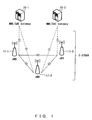
- ENBs 11-1 and 11-2 and eNBs 11-2 and 11-3 are under the control of an MME/SAE gateway 10-1 and 10-2, respectively.
- the MME/SAE gateways 10-1 and 10-2 and the eNB11-1 through 11-3 are connected by the S1 interface.
- the eNBs 11-1 through 11-3 are connected by the X2 interface.
- the network between the eNBs 11-1 through 11-3 is E-UTRAN.
- Fig. 2 explains the transmission route of user data at the time of a handover.
- a mobile station 13 is under the control of a source eNB 11-1.
- User data transmitted from a higher-order network is transferred to the source eNB 11-1 side and the user data is wirelessly transmitted from the source eNB 11-1 to the mobile station 13.
- the mobile station 13 is handed over from the source eNB 11-1 to be under the control of a target eNB 11-2.
- the source eNB 11-1 transmits the user data to the target eNB 11-2.
- the target eNB 11-2 transmits the received user data to the mobile station 13.
- interfaces between the MME/SAE gateway 10 and the source eNB 11-1/target eNB 11-2 are S1 interfaces.
- An interface between the source eNB 11-1 and the target eNB 11-2 is an X2 interface.
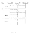
- Fig. 3 is a sequence chart at the time of a handover.
- user data is transmitted from an MME/SAE gateway to a mobile station UE via a source eNB.
- a handover H.O.
- the user data is transferred from the source eNB to a target eNB and then is transmitted to the mobile station UE.
- the mobile station UE is under the control of the target eNB and the user data is transmitted from the MME/SAE gateway to the mobile station UE via the target eNB.
- FIG. 4 A user data transfer sequence in the case where an X2 interface is not established is illustrated in Fig. 4 .
- user data is transmitted from an MME/SAE gateway to a mobile station UE via a source eNB.
- a handover H.O.
- the user data is transferred from the source eNB to a target eNB.
- the user data is transmitted from the source eNB to the MME/SAE gateway and is transmitted to the target eNB via the MME/SAE gateway.
- the user data is transmitted from the MME/SAE gateway to the mobile station UE via the target eNB.
- a H.O. process includes the transfer of user data between eNBs. It is one object of the handover process to enable UE to receive a series of user data (lossless handover) by this series of operations.
- a movement source device in order to activate a desired line when an inter-device interface is not activated, it is desired for a movement source device to recognize device information, such as an IP address, about a movement target device. Therefore, it is desired for respective devices to store respective device individual information (such as IP addresses and the like) constituting a line connection paying attention to a handover.
- Patent document 1 discloses a mobile telephone system for inquiring with a position information management center of the IP address of a network connection device connected to a radio base station in which a cellular phone to be called is positioned in the radio base station connected to the Internet via the network connection device and is connected to a communication line with a network connection device having the IP address.
- a communication system provided with a plurality of radio base station devices wirelessly communicating with a mobile station includes an address management unit comprising; an inquiry receiving unit for receiving the inquiry into the network address of a second radio base station device from a first radio base station device, upon the time of the mobile station under the control of the first radio base station device is handed over to the second radio base station device; a database unit for relating the network address of the first radio base station device to the network addresses of the radio base station devices having the possibility of having the mobile station device handed over to them from the first radio base station device, identifying a network address of the second radio base station device, which is a handover target candidate, and storing them; and a transmitting unit for obtaining the network address of the second radio base station device from the database unit in response to the inquiry and transmitting the network address to the first radio base station device, wherein an interface is established between the first and second radio base station devices.
- the embodiments can autonomously establish an interface required by respective devices constituting a system. For example, when there is no X2 interface between eNBs, a source eNB that has obtained target eNB information from a UE by a measurement report can establish an X2 interface by accessing an address management node existing on a network and obtaining the IP address of the target eNB and can perform a handover process between the eNBs.
- This preferred embodiment is provided with an address management node for managing the IP addresses of respective nodes of a network.
- an address management node for managing the IP addresses of respective nodes of a network.
- the function of an address management node can be provided as an independent server or provided in a source eNB, a target eNB, or an MME/SAE gateway, in the following explanation it is assumed that the function is provided as an independent server.
- a handover process starts.
- the source eNB may not transmit the user data to the target eNB. Therefore, the source eNB inquires with an address management node about the IP address of the target eNB and obtains the IP address. By the source eNB obtaining the IP address, an X2 interface is established between the source target eNBs. Then, the source eNB transfers the user data to the target eNB and then performs a handover process.
- respective network devices can establish desired interfaces by inquiring with the address management node about the device information (IP address and the like) of target devices and can perform a handover process via the interfaces.
- the load for network construction can be reduced compared with that of the case of respective devices managing their pieces of information, and even at the time of system extension, a line can be activated every handover from a mobile station only by updating the information of an individual information management node, thereby reducing the excessive load in a system design (office installation design) of an operator.
- Fig. 6 is a device configuration of a radio base station device according to the preferred embodiment of the present invention.
- the device information (IP address, etc.) acquisition process of a target eNB is performed by a CPU 27.
- Mast head amplifiers 20-1 through 20-3 amplify transmitting/received signals.
- a transmitting power amplifier 21 amplifies transmitting signals.
- TRXs 22-1 through 22-3 are transmitting units.
- BBs 23-1 through 23-3 are baseband units. Which of the baseband units 23-1 through 23-3 data is transmitted/received to/from is switched over by a switch 24.
- a database 28 stores data to be stored as a radio base station device.
- Common memory 26 is working memory.
- the CPU 27 performs various processes to be performed as a radio base station device.
- a highway interface 25 is an interface for connection to another network device.
- Fig. 7 is a network configuration having an address management function according to the preferred embodiment of the present invention.
- the source eNB 11-1 inquires with an address management unit 14 about the IP address of the target eNB 11-2 and obtains the IP address.
- An X2 interface is established between the source and target eNBs 11-1 and 11-2 according to the obtained IO address and user data is transferred from the source eNB 11-1 to the target eNB 11-2.
- This function to manage addresses exists not only as an independent node but can also be provided for an MME/SAE-GW, another ENB, and another system component device as a function unit.
- Fig. 8 is a configuration in the case where an MME/SAE-GW includes an address management function unit.
- the source eNB 11-1 inquires with an address management unit 14 about the IP address of the target eNB 11-2 and obtains the IP address.
- An X2 interface is established between the source and target eNBs 11-1 and 11-2 according to the obtained IO address and user data is transferred from the source eNB 11-1 to the target eNB 11-2.
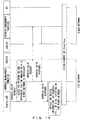
- Fig. 9 is a sequence chart of a handover in an MME/SAE-GW and between eNBs, using this preferred embodiment.
- respective eNBs including a target eNB transmit their individual identification IDs capable of specifying their own eNB to the UE.
- the area of a cell-ID is used and a new parameter is added without increasing a data area.
- the source eNB Upon receipt of the measurement report from the UE the source eNB obtaines information necessary for H.O. from the content of the report, including the above information.
- the source eNB determines whether an X2 interface is established with the target eNB being the H.O. target of the UE. If no X2 interface is established, the source eNB transmits an address solve request to the address management node in order to obtain an IP address that is the device information of the target eNB.
- This request stores a node ID, which is the individual identification ID of the target eNB previously obtained from the UE. Sometimes a network ID is attached as an option.
- the address management node solves the IP address of the target eNB based on this piece of information.
- the address management node stores a database related to the node IDs and the device information of respective eNBs and has a function to retrieve the device information of the eNB using a received key as a key.
- the address management node can focus retrieval targets only on eNBs which have a possibility that a UE can hand them over, based on the device information of a source eNB that has requested an address solution.
- the address management node stores a database in which node IDs and the IP addresses of respective eNBs are corresponded using device information as an IP address.
- the source eNB receives an address solve response from the address management node and obtains the IP address of the target eNB.
- an X2 interface which is a handover line, is established between source and target eNBs.
- the MME/SAE-GW Upon receipt of "H.O. complete", the MME/SAE-GW switches over the transmission target of the packet data from the source eNB to the target eNB and transmits "H.O. complete ACK" to the target eNB.
- Figs. 10 and 11 explain a cell-ID.
- a value regulated in a cell-ID can be expressed by 8 bits. However, its actually used range is very narrow and a cell-ID can be expressed by a value of less than the regulated number of bits.
- Fig. 10 is a usage example of a cell-ID area. However the number of bits is one example.
- a network identification ID "network ID” can be attached as an option.
- Fig. 11 is a cell-ID area in the case where a network ID is applied.
- an area applied to a existing cell-ID which is considered in an LTE, is divided into a network ID, which is an individual identification ID, a node ID and a cell-ID, and is used.
- the network ID and the node ID will be explained below.
- a network ID is an ID for identifying the network in a next-generation radio communication network.
- the address management node determines whether the address management node can make an inquiry, using this ID.
- next-generation radio communication network since an H.O. between a WLAN and a 3GPP network is also anticipated, whether H.O. is performed in the LTE or whether it is H.O. with a node belonging to another network can be distinguished using this ID.
- Fig. 12 is one example of an address table owned by the address management function.
- the address management function registers the IP addresses of eNBs having a possibility of being handed over, from among the IP addresses of respective source eNBs.
- the IP addresses of eNBs, registered as device information, are corresponded to node IDs and are registered.
- An address solve request received from a source eNB has parameters of the IP address of a source eNB, a network ID and a node ID, and returns the IP address of a handover target device to an address solve request source as an address solve response with reference to a table, as illustrated in Fig. 12 .
- Figs. 13 through 16 explain the IP focusing method of an address management node.
- Fig. 13 an address management node is connected to respective eNBs A, B, C and D.
- Fig. 14 is a "list of eNBs having a H.O. possibility" which exists in the address management node when the address management node is connected in Fig. 13 .
- connection target nodes of node A are nodes B and D.
- Nodes IDs are attached to the respective nodes, are related to respective pieces of device information, and are managed.
- the node E added to the network can be recognized in the respective tables of nodes A through D as a connection target.
- the above is performed by the network manager manually updating the table of the address management node.
- Fig. 17 is an address inquiry sequence chart for the address management function.
- the source eNB transmits an address solve request to the address management function (node) and receives an address solve response from the address management function. Since the source eNB can know the IP address of the target eNB in this way, the source eNB can establish an X2 interface.
- Fig. 18 is an address inquiry sequence chart for the address management function of another network.
- a source eNB issues an address solve request to the address management function of its own network (network A) .
- the address management function checks its network ID and determines that an inquiry with a network B is necessary. Then, the address management function of the network A issues an address solve request to the address management function of the network B.
- the address management function of the network B returns an address solve response to the address management function of the network A
- the address management function of the network A transfers this to the source eNB.
- the source eNB obtains the device information (IP address and the like) of a target eNB existing on the network B and establishes an X2 interface between the source and target eNBs.
- Protocol establishment sequencing for connecting between nodes can similarly be done using this method.
- the present invention has so far been studied based on a radio communication system based on a 3GPP network, the present invention is also applicable to another radio communication system, such as one based on a WiMAX network and the like.
- Fig. 19 is a sequence chart for establishing an interface across a WiMAX network and a 3GPP network (LTE network).
- ASN-GW and BS are devices provided with an AAA (roaming manager) function, a mobility (hand-off manager) function, and a mobile IP foreign agent function on a radio network and a radio base station device on a WiMAX network, respectively.
- the address management function disposed on an LTE network establishes an interface between a source eNB and BS by enabling the address management function to communicate with the address management function disposed on a WiMAX network across networks.
- the source eNB issues an address solve request to the address management function of its own network (LTE network)
- LTE network The address management function checks its network ID and determines that an inquiry with a WiMAX network is necessary. Then, the address management function of the LTE network issues an address solve request to the address management function of the WiMAX network. When the address management function of the WiMAX network returns an address solve response to the address management function of the LTE network, the address management function of the LTE network transfers this to the source eNB.
- the source eNB obtains the device information (IP address and the like) of the BS existing on the WiMAX network and establishes an interface between the source eNB and the BS.
- IP address and the like IP address and the like
- Fig. 20 is a sequence chart in the case where an address solution response is NG.
- a source eNB transmits an address solve request to an address management function
- an address solution becomes NG in the address management function. Therefore, the source eNB receives an address solve response of "NG".
- the source eNB may not establish an X2 interface with a target eNB and may not transmit user data. Therefore, the source eNB transmits the user data to the target eNB via an MME/SAE gateway (aGW).
- aGW MME/SAE gateway
- Fig. 21 is a flowchart up to the address solution of a source eNB.
- a source eNB receives a measurement report.
- the source eNB determines whether an X2 interface is established between the source eNB and a target eNB. If the determination in step S11 is Yes, the source eNB performs a handover process. If the determination in step S11 is No, in step S12, the source eNB requests an address solution of an address management node.
- the source eNB determines whether it can obtain its IP address from the address management node. If the determination in step S13 is No, the source eNB performs a handover via the MME/SAE gateway by transmitting user data. If the determination in step S13 is Yes, in step S14, the source eNB obtains the IP address of the target eNB from its own database and performs a handover by transmitting the user data via the target eNB.
- Fig. 22 is a flowchart up to the address solution in the case of including a network ID for network identification.
- a source eNB receives a measurement report.
- the source eNB determines whether an X2 interface is established between the source eNB and a target eNB. If the determination in step S21 is Yes, the source eNB performs a handover process. If the determination in step S21 is No, in step S22 the source eNB makes an inquiry with an address management node.
- the source eNB determines whether a network ID set in an address solve response received from the address management node is that of its own network. If the determination in step S23 is Yes, in step S24 the source eNB determines whether it can obtain its IP address from a node ID.
- step S24 the source eNB performs a handover process via an MME/SAE gateway. If the determination in step S24 is Yes, in step S25 the source eNB obtains the IP address of the target eNB from the table of the address management node and establishes an interface between the source and target eNBs. If the determination in step S23 is No, in step S26 the source eNB makes an inquiry with the address management node of another network. In step S27, the source eNB receives an address solve response. In step S28, the source eNB determines whether the address problem is solved. If the determination in step S28 is Yes, the source eNB establishes an inter-node interface between the source and target eNBs. If the determination in step S28 is No, the source eNB starts a handover process via the MME/SAE gateway.
- an X2 interface can be established by inquiring about the IP address of a target eNB of an address management node, thus transferring user data via an X2 interface.
Description
- The embodiment discussed herein is related to a communication system for conducting radio communications between base station devices and between a base station device and a base station control device.
- In a next-generation radio mobile communication system represented by LTE (long term evolution), a radio base station device (hereinafter called "eNB") constituting the radio mobile communication system is connected to an MME/SAE-GW device (base station control device), which is its higher-order device, and another base station device using an IP transmission path.
- The interfaces between eNBs and between an eNB and an MME/SAE-GW device are called "X2 interfaces" and "S1 interfaces", respectively. Interfaces between other devices are also discussed from the viewpoint of standardization (see 3GPP TR 23.882 3GPP System Architecture Evolution: Report on Technical Options and Conclusions and the like).
- Although in such a system an interface between respective devices constituting a radio mobile communication system can generally be arbitrarily set at the starting time of system, its setting method is semi-fixed and it is difficult to modify it during the operation of the system. Therefore, if a mobile station device (UE) existing in the system performs a handover accompanying area movement, it is desired to prepare its handover line in advance in a system on the handover-allowing side when the handover is performed with eNBs under the control of an MME/SAE-GW device or if the handover is performed between system areas (service areas) across MME/SAE-GW devices. A handover source base station device (hereinafter called source eNB) can transfer down-link (DL) data for a mobile station, received from an MME/SAE-GW device to a handover target base station device (hereinafter called "target eNB) in units of transmission (e.g., in units of RLC-SDU) and the target eNB can transfer the received data via the handover process to a mobile station device (hereinafter called "UE"). For example, when a line with a handover source base station device is not activated yet, a handover process as described above may not be performed.
- The basic configuration of eUTRA, the transmission route of user data at the time of a handover, and a sequence chart between devices at the time of a handover are illustrated in
Figs. 1 ,2 and3 , respectively. - ENBs 11-1 and 11-2 and eNBs 11-2 and 11-3 are under the control of an MME/SAE gateway 10-1 and 10-2, respectively. The MME/SAE gateways 10-1 and 10-2 and the eNB11-1 through 11-3 are connected by the S1 interface. The eNBs 11-1 through 11-3 are connected by the X2 interface. The network between the eNBs 11-1 through 11-3 is E-UTRAN.
-
Fig. 2 explains the transmission route of user data at the time of a handover. Firstly, it is assumed that amobile station 13 is under the control of a source eNB 11-1. User data transmitted from a higher-order network is transferred to the source eNB 11-1 side and the user data is wirelessly transmitted from the source eNB 11-1 to themobile station 13. Then, it is assumed that themobile station 13 is handed over from the source eNB 11-1 to be under the control of a target eNB 11-2. Then, the source eNB 11-1 transmits the user data to the target eNB 11-2. The target eNB 11-2 transmits the received user data to themobile station 13. In this case, interfaces between the MME/SAE gateway 10 and the source eNB 11-1/target eNB 11-2 are S1 interfaces. An interface between the source eNB 11-1 and the target eNB 11-2 is an X2 interface. -
Fig. 3 is a sequence chart at the time of a handover. - Firstly, user data is transmitted from an MME/SAE gateway to a mobile station UE via a source eNB. When a handover (H.O.) is started, the user data is transferred from the source eNB to a target eNB and then is transmitted to the mobile station UE. When the handover process is completed, the mobile station UE is under the control of the target eNB and the user data is transmitted from the MME/SAE gateway to the mobile station UE via the target eNB.
- It is assumed that if an H.O. request comes when, between eNBs, a source eNB does not store the IP address of a target eNB; that is, when an X2 interface is not established between eNBs, a handover is performed via an MME/SAE-GW between the source eNB and the target eNB (ex. R3-070695).
- A user data transfer sequence in the case where an X2 interface is not established is illustrated in
Fig. 4 . - Firstly, user data is transmitted from an MME/SAE gateway to a mobile station UE via a source eNB. When a handover (H.O.) is started, the user data is transferred from the source eNB to a target eNB. However, since an X2 interface is not established between the source eNB and the target eNB, the user data is transmitted from the source eNB to the MME/SAE gateway and is transmitted to the target eNB via the MME/SAE gateway. When a handover process is completed, the user data is transmitted from the MME/SAE gateway to the mobile station UE via the target eNB.
- As described above, in a handover operation accompanying the area movement of a mobile station, a H.O. process includes the transfer of user data between eNBs. It is one object of the handover process to enable UE to receive a series of user data (lossless handover) by this series of operations. However, as illustrated in
Fig. 3 , in order to activate a desired line when an inter-device interface is not activated, it is desired for a movement source device to recognize device information, such as an IP address, about a movement target device. Therefore, it is desired for respective devices to store respective device individual information (such as IP addresses and the like) constituting a line connection paying attention to a handover. (Alternatively, it is desired for respective devices to initially register the device information of all the component devices at the time of system activation and its extensibility is small.) However, since stored information (an IP address and the like) differs for each device and line setting between all the devices is not necessary, it becomes desired for setting/adjusting respective devices constituting a system according to an individual environment and much labor is required for an operator (for example, the design of a handover area/adjacent area and the like). Flexible correspondence to the extension of a system (the additional installment of devices and the modification of an operation form) becomes difficult. -
Patent document 1 discloses a mobile telephone system for inquiring with a position information management center of the IP address of a network connection device connected to a radio base station in which a cellular phone to be called is positioned in the radio base station connected to the Internet via the network connection device and is connected to a communication line with a network connection device having the IP address. - Patent document 1: Japanese Laid-open Patent Publication No.
11-150753 - Non-patent document 1: 3GPP TR 25. 912, [online], [retrieved on May 1, 2007], Internet <URL: http://www.3gpp.org/ftp/Specs/html-info/25-series.htm>
- Non-patent document 2: 3GPP TS25. 331, [online], [retrieved on May 29, 2007], Internet <URL: http://www.3gpp.org/ftp/Specs/html-info/25-series.htm>
- Non-patent document 3: 3GPP TR23. 882, [online], [retrieved on May 29, 2007], Internet <URL: http://www.3gpp.org/ftp/Specs/html-info/23-series.htm>
- Non-patent document 4: 3GPP R3-070695, [online], [retrieved on May 29, 2007], Internet <URL: http://www.3gpp.org/ftp/tsg_ran/WG3 Iu//TSGR3 55bis/docs/> "Discussion on Automatic Neighbour Relation Lists for LTE" from Ericsson, 3GPP DRAFT; S5-070974, 3rd Generation Partnership Project (3GPP), Mobile Competence Centre, 650 Route Des Lucioles, F-06921, France, XP050643795 (Sophia Antipolis Cedex) discloses a system for performing MCI handovers in which each cell maintains a Neighbor Relations List (NRL) for use in establishing X2 connections between cells.
- Accordingly, it is an object of the present invention to provide a communication system capable of communicating between devices between which an interface whose management is fairly simple and which is rich in extensibility has not been established.
- According to an aspect of the invention, a communication system provided with a plurality of radio base station devices wirelessly communicating with a mobile station includes an address management unit comprising; an inquiry receiving unit for receiving the inquiry into the network address of a second radio base station device from a first radio base station device, upon the time of the mobile station under the control of the first radio base station device is handed over to the second radio base station device; a database unit for relating the network address of the first radio base station device to the network addresses of the radio base station devices having the possibility of having the mobile station device handed over to them from the first radio base station device, identifying a network address of the second radio base station device, which is a handover target candidate, and storing them; and a transmitting unit for obtaining the network address of the second radio base station device from the database unit in response to the inquiry and transmitting the network address to the first radio base station device, wherein an interface is established between the first and second radio base station devices.
-
-
Fig. 1 is a basic configuration of eUTRA. -
Fig. 2 illustrates the transmission route of user data at the time of a handover. -
Fig. 3 is a sequence chart between devices at the time of a handover. -
Fig. 4 is user data transfer sequence when an X2 interface is not established yet. -
Fig. 5 is the sequence of processes according to the preferred embodiment of the present invention. -
Fig. 6 is a device configuration of a radio base station device according to the preferred embodiment of the present invention. -
Fig. 7 is a network configuration having an address management function according to the preferred embodiment of the present invention. -
Fig. 8 is a configuration in which an MME/SAE-GW includes an address management function unit. -
Fig. 9 is a sequence chart of a handover in an MME/SAE-GW and between eNBs, using this preferred embodiment. -
Fig. 10 explains a cell-ID (No. 1). -
Fig. 11 explains a cell-ID (No. 2). -
Fig. 12 is one example of an address table owned by the address management function. -
Fig. 13 explains the IP focusing method of an address management node (No. 1). -
Fig. 14 explains the IP focusing method of an address management node (No. 2). -
Fig. 15 explains the IP focusing method of an address management node (No. 3). -
Fig. 16 explains the IP focusing method of an address management node (No. 4). -
Fig. 17 is an address inquiry sequence chart for the address management function. -
Fig. 18 is an address inquiry sequence chart for the address management function of another network. -
Fig. 19 is an establishment sequence chart of an interface across a WiMAX network and a 3GPP network (LTE network). -
Fig. 20 is a sequence chart in the case where an address solution response is NG. -
Fig. 21 is a flowchart up to the address solution of a source eNB. -
Fig. 22 is a flowchart up to the address solution in the case of including a network ID for network identification. - The embodiments can autonomously establish an interface required by respective devices constituting a system. For example, when there is no X2 interface between eNBs, a source eNB that has obtained target eNB information from a UE by a measurement report can establish an X2 interface by accessing an address management node existing on a network and obtaining the IP address of the target eNB and can perform a handover process between the eNBs.
- The sequence of processes according to the preferred embodiment of the present invention is illustrated in
Fig. 5 . - This preferred embodiment is provided with an address management node for managing the IP addresses of respective nodes of a network. Although the function of an address management node can be provided as an independent server or provided in a source eNB, a target eNB, or an MME/SAE gateway, in the following explanation it is assumed that the function is provided as an independent server.
- When user data is transmitted to a mobile station UE from an MME/SAE gateway via a source eNB, a handover process starts. When the handover process starts, although it is desired for the source eNB to transmit the user data to a target eNB, an X2 interface is not established yet and does not know the IP address of the target eNB. Therefore, the source eNB may not transmit the user data to the target eNB. Therefore, the source eNB inquires with an address management node about the IP address of the target eNB and obtains the IP address. By the source eNB obtaining the IP address, an X2 interface is established between the source target eNBs. Then, the source eNB transfers the user data to the target eNB and then performs a handover process.
- When a line is not established with a target movement target device at the execution time of the handover of a mobile station, respective network devices can establish desired interfaces by inquiring with the address management node about the device information (IP address and the like) of target devices and can perform a handover process via the interfaces.
- By concentrating the device information management of respective devices on one node, the load for network construction can be reduced compared with that of the case of respective devices managing their pieces of information, and even at the time of system extension, a line can be activated every handover from a mobile station only by updating the information of an individual information management node, thereby reducing the excessive load in a system design (office installation design) of an operator.
-
Fig. 6 is a device configuration of a radio base station device according to the preferred embodiment of the present invention. - The device information (IP address, etc.) acquisition process of a target eNB is performed by a
CPU 27. Mast head amplifiers 20-1 through 20-3 amplify transmitting/received signals. A transmittingpower amplifier 21 amplifies transmitting signals. TRXs 22-1 through 22-3 are transmitting units. BBs 23-1 through 23-3 are baseband units. Which of the baseband units 23-1 through 23-3 data is transmitted/received to/from is switched over by aswitch 24. Adatabase 28 stores data to be stored as a radio base station device.Common memory 26 is working memory. TheCPU 27 performs various processes to be performed as a radio base station device. Ahighway interface 25 is an interface for connection to another network device. -
Fig. 7 is a network configuration having an address management function according to the preferred embodiment of the present invention. - When a
mobile station 13 is handed over from being under the control of a source eNB 11-1 to being under the control of a target eNB 11-2, the source eNB 11-1 inquires with anaddress management unit 14 about the IP address of the target eNB 11-2 and obtains the IP address. An X2 interface is established between the source and target eNBs 11-1 and 11-2 according to the obtained IO address and user data is transferred from the source eNB 11-1 to the target eNB 11-2. - This function to manage addresses exists not only as an independent node but can also be provided for an MME/SAE-GW, another ENB, and another system component device as a function unit.
-
Fig. 8 is a configuration in the case where an MME/SAE-GW includes an address management function unit. - When a
mobile station 13 is handed over from being under the control of a source eNB 11-1 to being under the control of a target eNB 11-2, the source eNB 11-1 inquires with anaddress management unit 14 about the IP address of the target eNB 11-2 and obtains the IP address. An X2 interface is established between the source and target eNBs 11-1 and 11-2 according to the obtained IO address and user data is transferred from the source eNB 11-1 to the target eNB 11-2. -
Fig. 9 is a sequence chart of a handover in an MME/SAE-GW and between eNBs, using this preferred embodiment. - (1) through (8) of the handover sequence will be explained.
- (1) State before H.O.: Packet data transmitted from an MME/SAE-GW is transmitted to a UE via a source eNB.
- (2) The UE collects information obtained from near-by eNBs and transmits a measurement report to the source eNB. The measurement report is a report from the UE to a radio base station office regulated in 3GPP TS 25.331 in which information about the intensity state of an electric wave sensed by a mobile state and the like are described. This piece of information is used to determine whether a handover should be performed.
- At this moment, respective eNBs including a target eNB transmit their individual identification IDs capable of specifying their own eNB to the UE. In this preferred embodiment it is assumed that the area of a cell-ID is used and a new parameter is added without increasing a data area.
- Upon receipt of the measurement report from the UE the source eNB obtaines information necessary for H.O. from the content of the report, including the above information.
- (3) The source eNB determines whether an X2 interface is established with the target eNB being the H.O. target of the UE. If no X2 interface is established, the source eNB transmits an address solve request to the address management node in order to obtain an IP address that is the device information of the target eNB.
- This request stores a node ID, which is the individual identification ID of the target eNB previously obtained from the UE. Sometimes a network ID is attached as an option. Upon receipt of this request, the address management node solves the IP address of the target eNB based on this piece of information.
- The address management node stores a database related to the node IDs and the device information of respective eNBs and has a function to retrieve the device information of the eNB using a received key as a key. The address management node can focus retrieval targets only on eNBs which have a possibility that a UE can hand them over, based on the device information of a source eNB that has requested an address solution.
- In an LTE system to which the present invention is applied, the address management node stores a database in which node IDs and the IP addresses of respective eNBs are corresponded using device information as an IP address. By focusing on a retrieval target using the IP address of a source eNB included in an address solve request, node IDs can be overlapped and the amount of data can be suppressed to a low level.
- If a response is NG when an inquiry is made with the address management node, user data is transferred via an MME/SAE-GW instead of establishing an X2 interface between source and target eNBs.
- The source eNB receives an address solve response from the address management node and obtains the IP address of the target eNB. Thus, an X2 interface, which is a handover line, is established between source and target eNBs.
- (4) The source eNB transmits an H.O. request to the target eNB and by receiving an H.O. response from the target eNB, the UE obtains information necessary for H.O. By transmitting an H.O. command to the UE, the source eNB notifies the target eNB of information necessary for connection.
- (5) Packet data to be forwarded from the MME/SAE-GW to the UE is transmitted to the source eNB. At this moment, the source eNB transfers the packet data received from the MME/SAE-GW from the source eNB to the target eNB, using the X2 interface established by (3).
- (6) The UE applies H.O. to the target eNB and, after the process is completed, transmits H.O. complete to the target eNB. Upon receipt of "H.O. complete", the target eNB transmits the H.O. complete to the MME/SAE-GW.
- Upon receipt of "H.O. complete", the MME/SAE-GW switches over the transmission target of the packet data from the source eNB to the target eNB and transmits "H.O. complete ACK" to the target eNB.
- (7) Upon receipt of "H.O. complete ACK", the target eNB transmits "release resource" to the source eNB and releases a packet-data storage buffer for target eNBs in the source eNB.
- (8) State after H.O. completion: The packet data transmitted from the MME/SAE-GW is transmitted to the UE via the source eNB.
-
Figs. 10 and11 explain a cell-ID. - Currently, a value regulated in a cell-ID can be expressed by 8 bits. However, its actually used range is very narrow and a cell-ID can be expressed by a value of less than the regulated number of bits.
Fig. 10 is a usage example of a cell-ID area. However the number of bits is one example. - Furthermore, a network identification ID "network ID" can be attached as an option.
Fig. 11 is a cell-ID area in the case where a network ID is applied. - In this preferred embodiment, an area applied to a existing cell-ID, which is considered in an LTE, is divided into a network ID, which is an individual identification ID, a node ID and a cell-ID, and is used. The network ID and the node ID will be explained below.
- A network ID is an ID for identifying the network in a next-generation radio communication network. The address management node determines whether the address management node can make an inquiry, using this ID.
- Furthermore, in the next-generation radio communication network, since an H.O. between a WLAN and a 3GPP network is also anticipated, whether H.O. is performed in the LTE or whether it is H.O. with a node belonging to another network can be distinguished using this ID.
-
Fig. 12 is one example of an address table owned by the address management function. - The address management function registers the IP addresses of eNBs having a possibility of being handed over, from among the IP addresses of respective source eNBs. The IP addresses of eNBs, registered as device information, are corresponded to node IDs and are registered. An address solve request received from a source eNB has parameters of the IP address of a source eNB, a network ID and a node ID, and returns the IP address of a handover target device to an address solve request source as an address solve response with reference to a table, as illustrated in
Fig. 12 . -
Figs. 13 through 16 explain the IP focusing method of an address management node. - In
Fig. 13 an address management node is connected to respective eNBs A, B, C and D.Fig. 14 is a "list of eNBs having a H.O. possibility" which exists in the address management node when the address management node is connected inFig. 13 . - According to
Fig. 14 , the connection target nodes of node A are nodes B and D. Nodes IDs are attached to the respective nodes, are related to respective pieces of device information, and are managed. - When a node E is newly disposed on the network illustrated in
Fig. 13 and the nodes are configured as illustrated inFig. 15 , it is desired to update the "list of eNBs having an H.O. possibility" which exists in the address management node, to the list illustrated inFig. 16 . - The node E added to the network can be recognized in the respective tables of nodes A through D as a connection target.
- The above is performed by the network manager manually updating the table of the address management node.
-
Fig. 17 is an address inquiry sequence chart for the address management function. - The source eNB transmits an address solve request to the address management function (node) and receives an address solve response from the address management function. Since the source eNB can know the IP address of the target eNB in this way, the source eNB can establish an X2 interface.
- If there is no combination of the node ID and an IP address in its own database when a network ID is attached to a cell-ID allocation area as an option and IP address retrieval is performed in the address management, an inquiry with another address management node is made possible.
-
Fig. 18 is an address inquiry sequence chart for the address management function of another network. - In
Fig. 18 it is assumed that different networks A and B are connected by a router, for convenience' sake. A source eNB issues an address solve request to the address management function of its own network (network A) . The address management function checks its network ID and determines that an inquiry with a network B is necessary. Then, the address management function of the network A issues an address solve request to the address management function of the network B. When the address management function of the network B returns an address solve response to the address management function of the network A, the address management function of the network A transfers this to the source eNB. Thus, the source eNB obtains the device information (IP address and the like) of a target eNB existing on the network B and establishes an X2 interface between the source and target eNBs. - Protocol establishment sequencing for connecting between nodes can similarly be done using this method.
- Although the present invention has so far been studied based on a radio communication system based on a 3GPP network, the present invention is also applicable to another radio communication system, such as one based on a WiMAX network and the like.
-
Fig. 19 is a sequence chart for establishing an interface across a WiMAX network and a 3GPP network (LTE network). - In this case, ASN-GW and BS (base station) are devices provided with an AAA (roaming manager) function, a mobility (hand-off manager) function, and a mobile IP foreign agent function on a radio network and a radio base station device on a WiMAX network, respectively.
- In this case, the address management function disposed on an LTE network establishes an interface between a source eNB and BS by enabling the address management function to communicate with the address management function disposed on a WiMAX network across networks.
- Although respective address management functions existing in the LTE and WiMAX networks perform a connection sequence between the address management functions, at this moment an address solution is possible while the existing device configuration of an ASN-GW is left as it is without any influence acting on it when the ASN-GW is passed through.
- The source eNB issues an address solve request to the address management function of its own network (LTE network) The address management function checks its network ID and determines that an inquiry with a WiMAX network is necessary. Then, the address management function of the LTE network issues an address solve request to the address management function of the WiMAX network. When the address management function of the WiMAX network returns an address solve response to the address management function of the LTE network, the address management function of the LTE network transfers this to the source eNB. Thus, the source eNB obtains the device information (IP address and the like) of the BS existing on the WiMAX network and establishes an interface between the source eNB and the BS.
-
Fig. 20 is a sequence chart in the case where an address solution response is NG. - Although a source eNB transmits an address solve request to an address management function, an address solution becomes NG in the address management function. Therefore, the source eNB receives an address solve response of "NG". Thus, the source eNB may not establish an X2 interface with a target eNB and may not transmit user data. Therefore, the source eNB transmits the user data to the target eNB via an MME/SAE gateway (aGW).
-
Fig. 21 is a flowchart up to the address solution of a source eNB. - In step S10 a source eNB receives a measurement report. In step S11, the source eNB determines whether an X2 interface is established between the source eNB and a target eNB. If the determination in step S11 is Yes, the source eNB performs a handover process. If the determination in step S11 is No, in step S12, the source eNB requests an address solution of an address management node. In step S13, the source eNB determines whether it can obtain its IP address from the address management node. If the determination in step S13 is No, the source eNB performs a handover via the MME/SAE gateway by transmitting user data. If the determination in step S13 is Yes, in step S14, the source eNB obtains the IP address of the target eNB from its own database and performs a handover by transmitting the user data via the target eNB.
-
Fig. 22 is a flowchart up to the address solution in the case of including a network ID for network identification. - In step S20, a source eNB receives a measurement report. In step S21, the source eNB determines whether an X2 interface is established between the source eNB and a target eNB. If the determination in step S21 is Yes, the source eNB performs a handover process. If the determination in step S21 is No, in step S22 the source eNB makes an inquiry with an address management node. In step S23, the source eNB determines whether a network ID set in an address solve response received from the address management node is that of its own network. If the determination in step S23 is Yes, in step S24 the source eNB determines whether it can obtain its IP address from a node ID. If the determination in step S24 is No, the source eNB performs a handover process via an MME/SAE gateway. If the determination in step S24 is Yes, in step S25 the source eNB obtains the IP address of the target eNB from the table of the address management node and establishes an interface between the source and target eNBs. If the determination in step S23 is No, in step S26 the source eNB makes an inquiry with the address management node of another network. In step S27, the source eNB receives an address solve response. In step S28, the source eNB determines whether the address problem is solved. If the determination in step S28 is Yes, the source eNB establishes an inter-node interface between the source and target eNBs. If the determination in step S28 is No, the source eNB starts a handover process via the MME/SAE gateway.
- According to the above preferred embodiments, an X2 interface can be established by inquiring about the IP address of a target eNB of an address management node, thus transferring user data via an X2 interface.
Claims (15)
- A communication system provided with a mobile station (13) and a plurality of radio base station devices, the communication system including an address management unit (14) comprising:inquiry receiving means for receiving an inquiry about a network address of a second radio base station (11-2) device from any first radio base station device (11-1) from among the plurality of radio base station devices, upon a time of a mobile station (13) under the control of the first radio base station device (11-1) is handed over to the control of the second radio base station device (11-2) as a trigger;database means for corresponding a network address of the first radio base station device (11-1) to network addresses of the radio base station devices having the possibility of having the mobile station (13) handed over to them from the first radio base station device (11-1), from among the plurality of radio base station devices (11-1, 11-2), identifying a network address of the second radio base station device (11-2) which is a handover target, and storing the correspondence; anda transmitting means for obtaining a network address of the second radio base station device (11-2) from the database means based on the inquiry and transmitting the obtained network address to the first radio base station device (11-1), whereinthe first radio base station device (11-1) establishes an interface with the second radio base station device (11-2).
- The communication system according to claim 1, wherein
the inquiry includes identifiers of the second radio base station device (11-2). - The communication system according to claim 1, wherein
the inquiry includes identifiers of a network to which the second radio base station device (11-1) belongs. - The communication system according to claim 1, wherein
the inquiry includes network addresses of the first radio base station device (11-1). - The communication system according to claim 1, wherein
the database means stores a table containing identifiers and network addresses of the radio base station devices having the possibility of having the mobile station (13) handed over to them from the first radio base station device (11-1), from among the plurality of radio base station devices (11-1, 11-2), for each network address of the first radio base station device (11-1), and identifiers of at least one of the radio base station devices from the radio base station devices having the possibility of having the mobile station (13) handed over from the first radio base station device (11-1) are overlapped between different tables. - The communication system according to claim 1, wherein
when a network to which the first radio base station device (11-1) belongs and a network to which the second radio base station device (11-2) belongs differ, a request for transmitting a network address of the second radio base station device (11-2) to a communication system to which the second radio base station device (11-2) belongs is made. - A communication system, wherein
functions of the communication system according to claim 1 are independent network nodes. - A communication system, wherein
functions of the communication system according to claim 1 are mounted on respective radio base station devices. - A communication system, wherein
functions of the communication system according to claim 1 are mounted on respective radio base station control devices (10, 10a). - The communication system of claim 1, wherein
when the communication system may not obtain a network address of the second radio base station device (11-2), the system is configured such that the first radio base station device (11-1) and the second radio base station device (11-2) communicate with each other via a base station control device (10, 10a). - The communication system according to claim 1, wherein
the inquiry is made when an interface is not established between the first radio base station device (11-1) and the second radio base station device (11-2). - A control method for a communication system provided with an address management unit (14), the address management unit (14) comprising a database means for corresponding a network address of any first radio base station device (11-1) (11-1) from among the plurality of radio base station devices to a network address of a second radio base station device (11-2), which is a handover target, and storing the correspondence, the control method comprising:receiving an inquiry at the address management unit (14) about a network address of a second radio base station device (11-2) from a first radio base station device (11-1), wherein a use time of a mobile station (13) under the control of the first radio base station device (11-1) is handed over to the control of the second radio base station device (11-2) as a trigger;obtaining a network address of the second radio base station device (11-2) from the database means based on the inquiry, wherein the database means is configured to correspond the network address of the first radio base station device (11-1) to network addresses of the radio base station devices having the possibility of having the mobile station (13) handed over to them from the first radio base station device (11-1), from among the plurality of radio base station devices (11-1, 11-2), identifying the network address of the second radio base station device (11-2) which is a handover target, and storing the correspondence and transmitting the obtained network address to the first radio base station device (11-1); andestablishing an interface between the first radio base station device (11-1) and the second radio base station device (11-2).
- The control method according to claim 12, wherein
when a network address of the second radio base station device (11-2) may not be obtained, the first radio base station device (11-1) and the second radio base station device (11-2) communicate with each other via a radio base station control device (10, 10a). - The control method according to claim 12, wherein
the inquiry is made when an interface is not established between the first radio base station device (11-1) and the second radio base station device (11-2). - The control method according to claim 12, wherein
when the second radio base station device (11-2) belongs to a network different from a network to which the communication system belongs, an inquiry is made with another communication system belonging to the different network.
Applications Claiming Priority (1)
| Application Number | Priority Date | Filing Date | Title |
|---|---|---|---|
| PCT/JP2007/001251 WO2009066337A1 (en) | 2007-11-19 | 2007-11-19 | Communication system |
Publications (3)
| Publication Number | Publication Date |
|---|---|
| EP2214452A1 EP2214452A1 (en) | 2010-08-04 |
| EP2214452A4 EP2214452A4 (en) | 2013-09-25 |
| EP2214452B1 true EP2214452B1 (en) | 2015-09-23 |
Family
ID=40667178
Family Applications (1)
| Application Number | Title | Priority Date | Filing Date |
|---|---|---|---|
| EP07828028.6A Not-in-force EP2214452B1 (en) | 2007-11-19 | 2007-11-19 | Communication system |
Country Status (6)
| Country | Link |
|---|---|
| US (1) | US8391869B2 (en) |
| EP (1) | EP2214452B1 (en) |
| JP (1) | JP5018892B2 (en) |
| KR (1) | KR101209389B1 (en) |
| CN (1) | CN101889462B (en) |
| WO (1) | WO2009066337A1 (en) |
Families Citing this family (30)
| Publication number | Priority date | Publication date | Assignee | Title |
|---|---|---|---|---|
| EP2237587A4 (en) * | 2008-01-31 | 2017-03-22 | NEC Corporation | Radio communication system, base station device, gateway device, and radio communication method |
| JP5035191B2 (en) | 2008-09-18 | 2012-09-26 | 富士通株式会社 | Base station apparatus, communication control system, communication control method, inter-station control method, and inter-station control program |
| CN101938758B (en) * | 2009-07-02 | 2015-05-13 | 中兴通讯股份有限公司 | Acquisition method and device of user interface connecting state |
| CN101965028B (en) * | 2009-07-23 | 2015-08-12 | 中兴通讯股份有限公司 | A kind of method, Apparatus and system realizing X2 and switch |
| US8437298B2 (en) | 2009-07-29 | 2013-05-07 | Qualcomm Incorporated | Methods and apparatus for blind interference decrease/cancellation techniques |
| CN102036322A (en) * | 2009-09-28 | 2011-04-27 | 中兴通讯股份有限公司 | Method and device for determining connection state of X2 user plane |
| US8570963B2 (en) * | 2009-10-26 | 2013-10-29 | Qualcomm Incorporated | Coordinated multi-point (CoMP) network and protocol architecture |
| CN102065565B (en) * | 2009-11-11 | 2015-04-01 | 中兴通讯股份有限公司 | Method for reporting information required by the establishment of inter-home node B direct interface and home node B |
| JP5492546B2 (en) * | 2009-12-24 | 2014-05-14 | 京セラ株式会社 | Wireless base station and connection establishment control method |
| CN101765172A (en) * | 2010-01-21 | 2010-06-30 | 华为技术有限公司 | Switching method and device in access point network |
| CN102687558B (en) * | 2010-03-19 | 2016-01-20 | 上海贝尔股份有限公司 | The method of local exchange and device between many base stations |
| US9332582B2 (en) * | 2010-04-30 | 2016-05-03 | Qualcomm Incorporated | System, apparatus and method for coordinating peer communication in wireless systems |
| CN105101320B (en) * | 2010-05-07 | 2019-12-31 | 北京三星通信技术研究有限公司 | Method for establishing connection between base stations |
| CN102238703B (en) * | 2010-05-07 | 2015-09-16 | 中兴通讯股份有限公司 | A kind of direct interface selects the method and system set up |
| US9031039B2 (en) * | 2010-05-14 | 2015-05-12 | Lg Electronics Inc. | Method and apparatus for performing handover procedure in wireless communication system |
| CN102369761B (en) * | 2010-05-28 | 2014-06-11 | 华为技术有限公司 | Processing method and equipment for acquiring context |
| CN103202092A (en) * | 2010-11-03 | 2013-07-10 | 瑞典爱立信有限公司 | A method and a network node for sharing information over an interface in a telecommunications system |
| WO2012074325A2 (en) * | 2010-12-03 | 2012-06-07 | Lg Electronics Inc. | Method and apparatus for performing access control in wireless communication system |
| US9386454B2 (en) * | 2011-03-11 | 2016-07-05 | Broadcom Corporation | Mechanism usable for validating a communication device for allowing usage of television radio bands/channels |
| JP5817051B2 (en) * | 2011-07-13 | 2015-11-18 | ▲ホア▼▲ウェイ▼技術有限公司 | Method, base station, and communication system for establishing an X2 connection between base stations |
| WO2013011439A1 (en) * | 2011-07-15 | 2013-01-24 | Renesas Mobile Corporation | Method and apparatus for establishing an intra-system interface |
| JP6027342B2 (en) * | 2012-06-01 | 2016-11-16 | 株式会社Nttドコモ | Wireless communication system, wireless base station, and communication method |
| CN103731920B (en) * | 2012-10-10 | 2019-04-23 | 中兴通讯股份有限公司 | Un subframe configuration method and device |
| US9294986B2 (en) * | 2013-10-17 | 2016-03-22 | Telefonaktiebolaget L M Ericsson (Publ) | Topology discovery based on explicit signaling |
| KR102169302B1 (en) * | 2014-04-30 | 2020-10-23 | 삼성전자주식회사 | A method, a terminal and a server for providing communication service |
| WO2016171657A1 (en) * | 2015-04-20 | 2016-10-27 | Nokia Solutions And Networks Oy | Method and apparatus for handling data activity of a secondary cell |
| US9344873B1 (en) * | 2015-06-15 | 2016-05-17 | Sprint Communications Company L.P. | Limiting data service for a home terminal roaming near home coverage |
| US10560424B2 (en) * | 2015-06-19 | 2020-02-11 | Sony Corporation | Apparatus and method |
| CN107294849B (en) * | 2016-04-13 | 2022-05-13 | 中兴通讯股份有限公司 | Method, device and system for establishing service path |
| EP3533255B1 (en) | 2016-10-26 | 2020-03-25 | Telefonaktiebolaget LM Ericsson (PUBL) | Wireless device and method performed therein for handling neighbour relationships in a wireless network |
Family Cites Families (14)
| Publication number | Priority date | Publication date | Assignee | Title |
|---|---|---|---|---|
| JP3228204B2 (en) | 1997-11-18 | 2001-11-12 | 日本電信電話株式会社 | Mobile phone system |
| US6628632B1 (en) | 1999-07-19 | 2003-09-30 | Lucent Technologies Inc. | Method and apparatus for permitting direct handoff between base stations in a wireless network |
| JP3625269B2 (en) * | 2000-03-14 | 2005-03-02 | 株式会社エヌ・ティ・ティ・ドコモ | Handover method, mobile station and base station |
| JP2003179616A (en) * | 2001-12-11 | 2003-06-27 | Matsushita Electric Ind Co Ltd | Communication equipment, communication terminal equipment and communication method |
| JP2004282652A (en) | 2003-03-19 | 2004-10-07 | Nec Corp | Mobile communication system, base station control apparatus and data transfer method to be used therefor |
| JP2004304394A (en) * | 2003-03-31 | 2004-10-28 | Hitachi Ltd | Wireless communication system |
| US7197307B2 (en) * | 2004-02-27 | 2007-03-27 | Nokia Corporation | Hard handover method and controller |
| CN100456883C (en) * | 2005-09-19 | 2009-01-28 | 华为技术有限公司 | Wireless switching method and system |
| KR100753220B1 (en) | 2005-12-30 | 2007-08-30 | 에스케이텔레시스 주식회사 | Handover supporting apparatus for wibro system and the method thereof |
| JP2007208595A (en) * | 2006-02-01 | 2007-08-16 | Fujitsu Ltd | Large-scale wide area network system having position information managing function |
| JPWO2007100108A1 (en) * | 2006-03-03 | 2009-07-23 | 株式会社エヌ・ティ・ティ・ドコモ | Base station and handover control method |
| CN100596229C (en) * | 2006-03-08 | 2010-03-24 | 华为技术有限公司 | Method for apprizing the binding result of the target network address and mobile user terminal |
| TWI493952B (en) * | 2006-12-27 | 2015-07-21 | Signal Trust For Wireless Innovation | Method and apparatus for base station self-configuration |
| US8559952B2 (en) * | 2007-08-14 | 2013-10-15 | Telefonaktiebolaget Lm Ericsson (Publ) | Automated and seamless change of reporting cell identity |
-
2007
- 2007-11-19 EP EP07828028.6A patent/EP2214452B1/en not_active Not-in-force
- 2007-11-19 CN CN200780101452.7A patent/CN101889462B/en not_active Expired - Fee Related
- 2007-11-19 WO PCT/JP2007/001251 patent/WO2009066337A1/en active Application Filing
- 2007-11-19 KR KR1020107010088A patent/KR101209389B1/en active IP Right Grant
- 2007-11-19 JP JP2009542402A patent/JP5018892B2/en not_active Expired - Fee Related
-
2010
- 2010-04-14 US US12/759,995 patent/US8391869B2/en not_active Expired - Fee Related
Also Published As
| Publication number | Publication date |
|---|---|
| US8391869B2 (en) | 2013-03-05 |
| EP2214452A4 (en) | 2013-09-25 |
| CN101889462B (en) | 2016-08-24 |
| WO2009066337A1 (en) | 2009-05-28 |
| US20100202410A1 (en) | 2010-08-12 |
| JPWO2009066337A1 (en) | 2011-03-31 |
| KR101209389B1 (en) | 2012-12-06 |
| KR20100072343A (en) | 2010-06-30 |
| CN101889462A (en) | 2010-11-17 |
| EP2214452A1 (en) | 2010-08-04 |
| JP5018892B2 (en) | 2012-09-05 |
Similar Documents
| Publication | Publication Date | Title |
|---|---|---|
| EP2214452B1 (en) | Communication system | |
| US10511962B2 (en) | Apparatuses, methods, and communication systems for performing communication via X2 interface | |
| US8634380B2 (en) | Inter-network handover system and method | |
| KR102057979B1 (en) | Handover Device and Method | |
| JP4796135B2 (en) | Method and network node for managing handover in a packet data communication environment | |
| EP2443885B1 (en) | Methods and nodes for setting up multiple packet data connections of a user equipment toward an access point | |
| US9560628B2 (en) | Method and node for paging in a radio access network | |
| US20110044290A1 (en) | Communication terminal apparatus and handover method | |
| GB2514806A (en) | Communications system | |
| JP2013123267A (en) | Control station, mobile station and mobile communication system | |
| US9877211B2 (en) | Dynamic management of an on/off status of a base station from a routing proxy | |
| KR101588241B1 (en) | Communication system, and path control method | |
| EP2486759A1 (en) | System and protocols for inter-mobility access gateway tunneling for fast handoff transition | |
| US20090180437A1 (en) | Communication apparatus and handover method | |
| KR20090054145A (en) | Method for performing fast handover traffic based on network | |
| JP5879112B2 (en) | Radio control apparatus, mobile communication system, and computer program | |
| EP2574104B1 (en) | Method, apparatus, and system for switching communication paths | |
| JP2017536728A (en) | Bearer processing method, apparatus, program, and recording medium | |
| JP4265980B2 (en) | Label path movement control method and label path movement control system |
Legal Events
| Date | Code | Title | Description |
|---|---|---|---|
| PUAI | Public reference made under article 153(3) epc to a published international application that has entered the european phase |
Free format text: ORIGINAL CODE: 0009012 |
|
| 17P | Request for examination filed |
Effective date: 20100614 |
|
| AK | Designated contracting states |
Kind code of ref document: A1 Designated state(s): AT BE BG CH CY CZ DE DK EE ES FI FR GB GR HU IE IS IT LI LT LU LV MC MT NL PL PT RO SE SI SK TR |
|
| AX | Request for extension of the european patent |
Extension state: AL BA HR MK RS |
|
| DAX | Request for extension of the european patent (deleted) | ||
| A4 | Supplementary search report drawn up and despatched |
Effective date: 20130822 |
|
| RIC1 | Information provided on ipc code assigned before grant |
Ipc: H04W 92/20 20090101ALN20130816BHEP Ipc: H04W 36/02 20090101AFI20130816BHEP |
|
| RIC1 | Information provided on ipc code assigned before grant |
Ipc: H04W 92/20 20090101ALN20131010BHEP Ipc: H04W 36/02 20090101AFI20131010BHEP |
|
| REG | Reference to a national code |
Ref country code: DE Ref legal event code: R079 Ref document number: 602007043267 Country of ref document: DE Free format text: PREVIOUS MAIN CLASS: H04W0084000000 Ipc: H04W0036020000 |
|
| GRAP | Despatch of communication of intention to grant a patent |
Free format text: ORIGINAL CODE: EPIDOSNIGR1 |
|
| RIC1 | Information provided on ipc code assigned before grant |
Ipc: H04W 36/02 20090101AFI20150401BHEP Ipc: H04W 92/20 20090101ALN20150401BHEP |
|
| RIC1 | Information provided on ipc code assigned before grant |
Ipc: H04W 36/02 20090101AFI20150414BHEP Ipc: H04W 92/20 20090101ALN20150414BHEP |
|
| INTG | Intention to grant announced |
Effective date: 20150430 |
|
| GRAS | Grant fee paid |
Free format text: ORIGINAL CODE: EPIDOSNIGR3 |
|
| GRAA | (expected) grant |
Free format text: ORIGINAL CODE: 0009210 |
|
| AK | Designated contracting states |
Kind code of ref document: B1 Designated state(s): AT BE BG CH CY CZ DE DK EE ES FI FR GB GR HU IE IS IT LI LT LU LV MC MT NL PL PT RO SE SI SK TR |
|
| REG | Reference to a national code |
Ref country code: GB Ref legal event code: FG4D |
|
| REG | Reference to a national code |
Ref country code: CH Ref legal event code: EP |
|
| REG | Reference to a national code |
Ref country code: AT Ref legal event code: REF Ref document number: 751795 Country of ref document: AT Kind code of ref document: T Effective date: 20151015 |
|
| REG | Reference to a national code |
Ref country code: IE Ref legal event code: FG4D |
|
| REG | Reference to a national code |
Ref country code: FR Ref legal event code: PLFP Year of fee payment: 9 |
|
| REG | Reference to a national code |
Ref country code: DE Ref legal event code: R096 Ref document number: 602007043267 Country of ref document: DE |
|
| REG | Reference to a national code |
Ref country code: NL Ref legal event code: MP Effective date: 20150923 |
|
| PG25 | Lapsed in a contracting state [announced via postgrant information from national office to epo] |
Ref country code: GR Free format text: LAPSE BECAUSE OF FAILURE TO SUBMIT A TRANSLATION OF THE DESCRIPTION OR TO PAY THE FEE WITHIN THE PRESCRIBED TIME-LIMIT Effective date: 20151224 Ref country code: LV Free format text: LAPSE BECAUSE OF FAILURE TO SUBMIT A TRANSLATION OF THE DESCRIPTION OR TO PAY THE FEE WITHIN THE PRESCRIBED TIME-LIMIT Effective date: 20150923 Ref country code: LT Free format text: LAPSE BECAUSE OF FAILURE TO SUBMIT A TRANSLATION OF THE DESCRIPTION OR TO PAY THE FEE WITHIN THE PRESCRIBED TIME-LIMIT Effective date: 20150923 Ref country code: FI Free format text: LAPSE BECAUSE OF FAILURE TO SUBMIT A TRANSLATION OF THE DESCRIPTION OR TO PAY THE FEE WITHIN THE PRESCRIBED TIME-LIMIT Effective date: 20150923 |
|
| REG | Reference to a national code |
Ref country code: LT Ref legal event code: MG4D |
|
| REG | Reference to a national code |
Ref country code: AT Ref legal event code: MK05 Ref document number: 751795 Country of ref document: AT Kind code of ref document: T Effective date: 20150923 |
|
| PG25 | Lapsed in a contracting state [announced via postgrant information from national office to epo] |
Ref country code: SE Free format text: LAPSE BECAUSE OF FAILURE TO SUBMIT A TRANSLATION OF THE DESCRIPTION OR TO PAY THE FEE WITHIN THE PRESCRIBED TIME-LIMIT Effective date: 20150923 |
|
| PG25 | Lapsed in a contracting state [announced via postgrant information from national office to epo] |
Ref country code: NL Free format text: LAPSE BECAUSE OF FAILURE TO SUBMIT A TRANSLATION OF THE DESCRIPTION OR TO PAY THE FEE WITHIN THE PRESCRIBED TIME-LIMIT Effective date: 20150923 |
|
| PG25 | Lapsed in a contracting state [announced via postgrant information from national office to epo] |
Ref country code: EE Free format text: LAPSE BECAUSE OF FAILURE TO SUBMIT A TRANSLATION OF THE DESCRIPTION OR TO PAY THE FEE WITHIN THE PRESCRIBED TIME-LIMIT Effective date: 20150923 Ref country code: SK Free format text: LAPSE BECAUSE OF FAILURE TO SUBMIT A TRANSLATION OF THE DESCRIPTION OR TO PAY THE FEE WITHIN THE PRESCRIBED TIME-LIMIT Effective date: 20150923 Ref country code: ES Free format text: LAPSE BECAUSE OF FAILURE TO SUBMIT A TRANSLATION OF THE DESCRIPTION OR TO PAY THE FEE WITHIN THE PRESCRIBED TIME-LIMIT Effective date: 20150923 Ref country code: CZ Free format text: LAPSE BECAUSE OF FAILURE TO SUBMIT A TRANSLATION OF THE DESCRIPTION OR TO PAY THE FEE WITHIN THE PRESCRIBED TIME-LIMIT Effective date: 20150923 Ref country code: IS Free format text: LAPSE BECAUSE OF FAILURE TO SUBMIT A TRANSLATION OF THE DESCRIPTION OR TO PAY THE FEE WITHIN THE PRESCRIBED TIME-LIMIT Effective date: 20160123 |
|
| PG25 | Lapsed in a contracting state [announced via postgrant information from national office to epo] |
Ref country code: RO Free format text: LAPSE BECAUSE OF FAILURE TO SUBMIT A TRANSLATION OF THE DESCRIPTION OR TO PAY THE FEE WITHIN THE PRESCRIBED TIME-LIMIT Effective date: 20150923 Ref country code: PT Free format text: LAPSE BECAUSE OF FAILURE TO SUBMIT A TRANSLATION OF THE DESCRIPTION OR TO PAY THE FEE WITHIN THE PRESCRIBED TIME-LIMIT Effective date: 20160125 Ref country code: PL Free format text: LAPSE BECAUSE OF FAILURE TO SUBMIT A TRANSLATION OF THE DESCRIPTION OR TO PAY THE FEE WITHIN THE PRESCRIBED TIME-LIMIT Effective date: 20150923 Ref country code: AT Free format text: LAPSE BECAUSE OF FAILURE TO SUBMIT A TRANSLATION OF THE DESCRIPTION OR TO PAY THE FEE WITHIN THE PRESCRIBED TIME-LIMIT Effective date: 20150923 |
|
| REG | Reference to a national code |
Ref country code: DE Ref legal event code: R097 Ref document number: 602007043267 Country of ref document: DE |
|
| PG25 | Lapsed in a contracting state [announced via postgrant information from national office to epo] |
Ref country code: MC Free format text: LAPSE BECAUSE OF FAILURE TO SUBMIT A TRANSLATION OF THE DESCRIPTION OR TO PAY THE FEE WITHIN THE PRESCRIBED TIME-LIMIT Effective date: 20150923 Ref country code: LU Free format text: LAPSE BECAUSE OF FAILURE TO SUBMIT A TRANSLATION OF THE DESCRIPTION OR TO PAY THE FEE WITHIN THE PRESCRIBED TIME-LIMIT Effective date: 20151119 |
|
| REG | Reference to a national code |
Ref country code: CH Ref legal event code: PL |
|
| PG25 | Lapsed in a contracting state [announced via postgrant information from national office to epo] |
Ref country code: CH Free format text: LAPSE BECAUSE OF NON-PAYMENT OF DUE FEES Effective date: 20151130 Ref country code: LI Free format text: LAPSE BECAUSE OF NON-PAYMENT OF DUE FEES Effective date: 20151130 |
|
| PLBE | No opposition filed within time limit |
Free format text: ORIGINAL CODE: 0009261 |
|
| STAA | Information on the status of an ep patent application or granted ep patent |
Free format text: STATUS: NO OPPOSITION FILED WITHIN TIME LIMIT |
|
| REG | Reference to a national code |
Ref country code: IE Ref legal event code: MM4A |
|
| 26N | No opposition filed |
Effective date: 20160624 |
|
| PG25 | Lapsed in a contracting state [announced via postgrant information from national office to epo] |
Ref country code: DK Free format text: LAPSE BECAUSE OF FAILURE TO SUBMIT A TRANSLATION OF THE DESCRIPTION OR TO PAY THE FEE WITHIN THE PRESCRIBED TIME-LIMIT Effective date: 20150923 |
|
| REG | Reference to a national code |
Ref country code: FR Ref legal event code: PLFP Year of fee payment: 10 |
|
| PG25 | Lapsed in a contracting state [announced via postgrant information from national office to epo] |
Ref country code: IE Free format text: LAPSE BECAUSE OF NON-PAYMENT OF DUE FEES Effective date: 20151119 |
|
| PG25 | Lapsed in a contracting state [announced via postgrant information from national office to epo] |
Ref country code: SI Free format text: LAPSE BECAUSE OF FAILURE TO SUBMIT A TRANSLATION OF THE DESCRIPTION OR TO PAY THE FEE WITHIN THE PRESCRIBED TIME-LIMIT Effective date: 20150923 |
|
| PG25 | Lapsed in a contracting state [announced via postgrant information from national office to epo] |
Ref country code: BE Free format text: LAPSE BECAUSE OF FAILURE TO SUBMIT A TRANSLATION OF THE DESCRIPTION OR TO PAY THE FEE WITHIN THE PRESCRIBED TIME-LIMIT Effective date: 20150923 |
|
| PG25 | Lapsed in a contracting state [announced via postgrant information from national office to epo] |
Ref country code: BG Free format text: LAPSE BECAUSE OF FAILURE TO SUBMIT A TRANSLATION OF THE DESCRIPTION OR TO PAY THE FEE WITHIN THE PRESCRIBED TIME-LIMIT Effective date: 20150923 Ref country code: HU Free format text: LAPSE BECAUSE OF FAILURE TO SUBMIT A TRANSLATION OF THE DESCRIPTION OR TO PAY THE FEE WITHIN THE PRESCRIBED TIME-LIMIT; INVALID AB INITIO Effective date: 20071119 |
|
| PG25 | Lapsed in a contracting state [announced via postgrant information from national office to epo] |
Ref country code: CY Free format text: LAPSE BECAUSE OF FAILURE TO SUBMIT A TRANSLATION OF THE DESCRIPTION OR TO PAY THE FEE WITHIN THE PRESCRIBED TIME-LIMIT Effective date: 20150923 |
|
| PG25 | Lapsed in a contracting state [announced via postgrant information from national office to epo] |
Ref country code: TR Free format text: LAPSE BECAUSE OF FAILURE TO SUBMIT A TRANSLATION OF THE DESCRIPTION OR TO PAY THE FEE WITHIN THE PRESCRIBED TIME-LIMIT Effective date: 20150923 Ref country code: MT Free format text: LAPSE BECAUSE OF FAILURE TO SUBMIT A TRANSLATION OF THE DESCRIPTION OR TO PAY THE FEE WITHIN THE PRESCRIBED TIME-LIMIT Effective date: 20150923 |
|
| REG | Reference to a national code |
Ref country code: FR Ref legal event code: PLFP Year of fee payment: 11 |
|
| REG | Reference to a national code |
Ref country code: FR Ref legal event code: PLFP Year of fee payment: 12 |
|
| PGFP | Annual fee paid to national office [announced via postgrant information from national office to epo] |
Ref country code: DE Payment date: 20181106 Year of fee payment: 12 |
|
| PGFP | Annual fee paid to national office [announced via postgrant information from national office to epo] |
Ref country code: FR Payment date: 20181011 Year of fee payment: 12 Ref country code: IT Payment date: 20181122 Year of fee payment: 12 Ref country code: GB Payment date: 20181114 Year of fee payment: 12 |
|
| REG | Reference to a national code |
Ref country code: DE Ref legal event code: R119 Ref document number: 602007043267 Country of ref document: DE |
|
| GBPC | Gb: european patent ceased through non-payment of renewal fee |
Effective date: 20191119 |
|
| PG25 | Lapsed in a contracting state [announced via postgrant information from national office to epo] |
Ref country code: DE Free format text: LAPSE BECAUSE OF NON-PAYMENT OF DUE FEES Effective date: 20200603 Ref country code: FR Free format text: LAPSE BECAUSE OF NON-PAYMENT OF DUE FEES Effective date: 20191130 Ref country code: IT Free format text: LAPSE BECAUSE OF NON-PAYMENT OF DUE FEES Effective date: 20191119 Ref country code: GB Free format text: LAPSE BECAUSE OF NON-PAYMENT OF DUE FEES Effective date: 20191119 |