EP2201986A1 - Handle designed to be connected to a system for resisting a force of a bodybuilding and/or re-education machine - Google Patents
Handle designed to be connected to a system for resisting a force of a bodybuilding and/or re-education machine Download PDFInfo
- Publication number
- EP2201986A1 EP2201986A1 EP08306015A EP08306015A EP2201986A1 EP 2201986 A1 EP2201986 A1 EP 2201986A1 EP 08306015 A EP08306015 A EP 08306015A EP 08306015 A EP08306015 A EP 08306015A EP 2201986 A1 EP2201986 A1 EP 2201986A1
- Authority
- EP
- European Patent Office
- Prior art keywords
- handle
- handle according
- main body
- shell
- bar
- Prior art date
- Legal status (The legal status is an assumption and is not a legal conclusion. Google has not performed a legal analysis and makes no representation as to the accuracy of the status listed.)
- Withdrawn
Links
Images


Classifications
-
- A—HUMAN NECESSITIES
- A63—SPORTS; GAMES; AMUSEMENTS
- A63B—APPARATUS FOR PHYSICAL TRAINING, GYMNASTICS, SWIMMING, CLIMBING, OR FENCING; BALL GAMES; TRAINING EQUIPMENT
- A63B21/00—Exercising apparatus for developing or strengthening the muscles or joints of the body by working against a counterforce, with or without measuring devices
- A63B21/15—Arrangements for force transmissions
- A63B21/151—Using flexible elements for reciprocating movements, e.g. ropes or chains
- A63B21/154—Using flexible elements for reciprocating movements, e.g. ropes or chains using special pulley-assemblies
-
- A—HUMAN NECESSITIES
- A63—SPORTS; GAMES; AMUSEMENTS
- A63B—APPARATUS FOR PHYSICAL TRAINING, GYMNASTICS, SWIMMING, CLIMBING, OR FENCING; BALL GAMES; TRAINING EQUIPMENT
- A63B21/00—Exercising apparatus for developing or strengthening the muscles or joints of the body by working against a counterforce, with or without measuring devices
- A63B21/40—Interfaces with the user related to strength training; Details thereof
- A63B21/4001—Arrangements for attaching the exercising apparatus to the user's body, e.g. belts, shoes or gloves specially adapted therefor
- A63B21/4017—Arrangements for attaching the exercising apparatus to the user's body, e.g. belts, shoes or gloves specially adapted therefor to the upper limbs
-
- A—HUMAN NECESSITIES
- A63—SPORTS; GAMES; AMUSEMENTS
- A63B—APPARATUS FOR PHYSICAL TRAINING, GYMNASTICS, SWIMMING, CLIMBING, OR FENCING; BALL GAMES; TRAINING EQUIPMENT
- A63B21/00—Exercising apparatus for developing or strengthening the muscles or joints of the body by working against a counterforce, with or without measuring devices
- A63B21/40—Interfaces with the user related to strength training; Details thereof
- A63B21/4027—Specific exercise interfaces
- A63B21/4033—Handles, pedals, bars or platforms
- A63B21/4035—Handles, pedals, bars or platforms for operation by hand
-
- A—HUMAN NECESSITIES
- A63—SPORTS; GAMES; AMUSEMENTS
- A63B—APPARATUS FOR PHYSICAL TRAINING, GYMNASTICS, SWIMMING, CLIMBING, OR FENCING; BALL GAMES; TRAINING EQUIPMENT
- A63B21/00—Exercising apparatus for developing or strengthening the muscles or joints of the body by working against a counterforce, with or without measuring devices
- A63B21/40—Interfaces with the user related to strength training; Details thereof
- A63B21/4041—Interfaces with the user related to strength training; Details thereof characterised by the movements of the interface
- A63B21/4047—Pivoting movement
-
- A—HUMAN NECESSITIES
- A63—SPORTS; GAMES; AMUSEMENTS
- A63B—APPARATUS FOR PHYSICAL TRAINING, GYMNASTICS, SWIMMING, CLIMBING, OR FENCING; BALL GAMES; TRAINING EQUIPMENT
- A63B23/00—Exercising apparatus specially adapted for particular parts of the body
- A63B23/035—Exercising apparatus specially adapted for particular parts of the body for limbs, i.e. upper or lower limbs, e.g. simultaneously
- A63B23/12—Exercising apparatus specially adapted for particular parts of the body for limbs, i.e. upper or lower limbs, e.g. simultaneously for upper limbs or related muscles, e.g. chest, upper back or shoulder muscles
- A63B23/1281—Exercising apparatus specially adapted for particular parts of the body for limbs, i.e. upper or lower limbs, e.g. simultaneously for upper limbs or related muscles, e.g. chest, upper back or shoulder muscles primarily by articulating the elbow joint
-
- A—HUMAN NECESSITIES
- A63—SPORTS; GAMES; AMUSEMENTS
- A63B—APPARATUS FOR PHYSICAL TRAINING, GYMNASTICS, SWIMMING, CLIMBING, OR FENCING; BALL GAMES; TRAINING EQUIPMENT
- A63B22/00—Exercising apparatus specially adapted for conditioning the cardio-vascular system, for training agility or co-ordination of movements
- A63B22/0025—Particular aspects relating to the orientation of movement paths of the limbs relative to the body; Relative relationship between the movements of the limbs
- A63B2022/0041—Particular aspects relating to the orientation of movement paths of the limbs relative to the body; Relative relationship between the movements of the limbs one hand moving independently from the other hand, i.e. there is no link between the movements of the hands
-
- A—HUMAN NECESSITIES
- A63—SPORTS; GAMES; AMUSEMENTS
- A63B—APPARATUS FOR PHYSICAL TRAINING, GYMNASTICS, SWIMMING, CLIMBING, OR FENCING; BALL GAMES; TRAINING EQUIPMENT
- A63B23/00—Exercising apparatus specially adapted for particular parts of the body
- A63B2023/003—Exercising apparatus specially adapted for particular parts of the body by torsion of the body part around its longitudinal axis
-
- A—HUMAN NECESSITIES
- A63—SPORTS; GAMES; AMUSEMENTS
- A63B—APPARATUS FOR PHYSICAL TRAINING, GYMNASTICS, SWIMMING, CLIMBING, OR FENCING; BALL GAMES; TRAINING EQUIPMENT
- A63B21/00—Exercising apparatus for developing or strengthening the muscles or joints of the body by working against a counterforce, with or without measuring devices
- A63B21/00058—Mechanical means for varying the resistance
- A63B21/00069—Setting or adjusting the resistance level; Compensating for a preload prior to use, e.g. changing length of resistance or adjusting a valve
-
- A—HUMAN NECESSITIES
- A63—SPORTS; GAMES; AMUSEMENTS
- A63B—APPARATUS FOR PHYSICAL TRAINING, GYMNASTICS, SWIMMING, CLIMBING, OR FENCING; BALL GAMES; TRAINING EQUIPMENT
- A63B21/00—Exercising apparatus for developing or strengthening the muscles or joints of the body by working against a counterforce, with or without measuring devices
- A63B21/02—Exercising apparatus for developing or strengthening the muscles or joints of the body by working against a counterforce, with or without measuring devices using resilient force-resisters
- A63B21/023—Wound springs
-
- A—HUMAN NECESSITIES
- A63—SPORTS; GAMES; AMUSEMENTS
- A63B—APPARATUS FOR PHYSICAL TRAINING, GYMNASTICS, SWIMMING, CLIMBING, OR FENCING; BALL GAMES; TRAINING EQUIPMENT
- A63B21/00—Exercising apparatus for developing or strengthening the muscles or joints of the body by working against a counterforce, with or without measuring devices
- A63B21/02—Exercising apparatus for developing or strengthening the muscles or joints of the body by working against a counterforce, with or without measuring devices using resilient force-resisters
- A63B21/045—Exercising apparatus for developing or strengthening the muscles or joints of the body by working against a counterforce, with or without measuring devices using resilient force-resisters having torsion or bending or flexion element
-
- A—HUMAN NECESSITIES
- A63—SPORTS; GAMES; AMUSEMENTS
- A63B—APPARATUS FOR PHYSICAL TRAINING, GYMNASTICS, SWIMMING, CLIMBING, OR FENCING; BALL GAMES; TRAINING EQUIPMENT
- A63B2208/00—Characteristics or parameters related to the user or player
- A63B2208/02—Characteristics or parameters related to the user or player posture
- A63B2208/0204—Standing on the feet
Definitions
- the present invention relates to a handle intended to be connected to a force resistance system, in particular by means of a cable or a moving bar, a weight training machine and / or a re-education machine.
- the bodybuilding and / or physical rehabilitation apparatus of the upper part of the human body in particular the torso and the arms, generally have a rigid structure, or structure, comprising for example a bench or a seat, one or more resistance to a force, operating in particular using real or virtual weights (friction, piston, springs or other means), cables, pulleys, bars / levers movable or articulated and hand grips.
- a rigid structure or structure, comprising for example a bench or a seat, one or more resistance to a force, operating in particular using real or virtual weights (friction, piston, springs or other means), cables, pulleys, bars / levers movable or articulated and hand grips.
- handles are basic, in the sense that they provide no other function than that of acting as a means of grip for the user. Simplifying, it is simply an interface between the (s) muscles (s) to work, for example the pectorals, back, biceps, triceps, deltoid, and a resistance system of the machine provided for example counterweight lift / let stand alternately.
- these handles are not optimized at all.
- the link they provide between the muscle to work and the resistance system of the machine the actions performed by the user can cause adverse constraints to training or rehabilitation said muscle.
- Micro traumas can occur not only to the muscles but also to the tendons or other organs.
- the use of these machines is often based on the repetition of a movement made several tens to hundreds of times. It is therefore easy to understand that it is essential to improve these handles for a better comfort of use and a better efficiency of the machines on which they are mounted.
- An object of the present invention is therefore to solve the problems mentioned above with a solution that is simple to implement, reliable and particularly ergonomic for the user.
- the present invention relates to a handle intended to be connected to a force resistance system, in particular by means of a cable or a mobile lever, a machine for weight training and / or rehabilitation, said handle comprising a rigid main body to which is connected a manual gripping means, characterized in that it further comprises a resilient return member connecting the manual gripping means to the main body and opposing a force induced by a user using the handle to operate the resistance system by moving the manual gripping means relative to the main body.
- the present invention also relates to a weight training and / or rehabilitation machine comprising a force resistance system connected to at least one handle as described above.
- the figure 1 represents a biceps muscle-building machine 10 of a user whose right arm (D), in the extended position, is shown on the left and the left arm (G), in the bent position, is shown on the right.
- this machine 10 comprises a rigid metal frame 11 between the uprights 12 of which a user 1 can sit on a seat 13.
- Each upright 12 of the frame 11 supports counterweights 14 connected to cables 15 cooperating with pulleys 16.
- Each cable is connected to an articulated lever 17 to which is attached a handle 20 according to the present invention.
- the handle 20 is also shown alone on the figure 5 , in the rest position, and on the figure 6 in position of use.
- This handle 20 comprises a rigid main body 21 forming a shell made for example of plastic and having a substantially hemispherical cavity 22.
- the cavity 22 has an opening 22a, an inner surface 22b and a main axis of symmetry XX '.
- a manual gripping means 23 such as a round section bar, extends diametrically across the opening 22a.
- This bar 23 is made integral with a metal inner ring 24, for example by welding, having outer peripheral surface 24a shaped sphere portion cooperating with the inner surface 25a of a peripheral ring 25 made of plastic and mounted for example in force in the hemispherical cavity 22.
- the collaboration of the inner ring 24 and the peripheral ring 25 forms a spherical ball joint connection allowing the gripping bar 23 to pivot on an angle ⁇ measuring ⁇ 20 °, with respect to a position initial rest, with respect to the main body 21, this rotation being along any axis ZZ 'perpendicular to the main axis XX'.
- the peripheral ring 25 is made of a plastic material having a quality of hardness and sliding allowing the bar 23 to rotate freely, with limited friction.
- An elastic return member 30, such as a helical torsion spring 31, connects the gripping bar 23 to the main body 21. More precisely, a helical spring 31 with round section turns 32 extends into the hemispherical cavity 22, between a fastening tab 33 secured to the gripping bar 23 and a bottom plate 34 to which it is welded. The spring 31 is fixed to the tongue 33 by a rivet 35. The turns 32 of the coil spring 31 spirally wind and fit the inner surface 22b of the hemispherical cavity 22.
- the coil spring 31 has a determined and identical torsional stiffness coefficient in both directions of possible twist.
- An adjustment means 36 of the stiffness of the coil spring 31, accessible from outside the handle 20, is provided at the top 21b of the shell 21.
- This means 36 is in the form of a button 37 movable in translation (arrow TR) and rotation (arrow R) linked to the bottom plate 34 with screws 38 so as to act on the stiffness of the coil spring 31 by tightening or loosening its turns 32. Once the stiffness determined, the button 37 is locked in the selected position via a pin 39 penetrating into a cavity 40 of the main body 21.
- the main body 21 of the handle 20 is secured to the lever 17 by means of a strapping 42 having locally a housing 44 receiving the end of said lever and belonging to a sleeve 43.
- a pin 45 is also provided to temporarily connect the spring 31 to the shell 21 through the strapping 42 to prevent the rotation of the handle 20 when adjusting the stiffness of the spring.
- the operation of the handle 20 is as follows.
- the handle 20 is for example in the lower position, as illustrated on the left side of the figure 1 . No force is exerted on the weights 14 which remain stacked.
- the hand catches the handle in the neutral position, inch forward.
- the movement then consists in turning the forearm simultaneously with its ascent, so as to bring the hands supinated, that is to say, inches outwards.
- This is called phasic work.
- This rotation is against the resistance of the spring 31 engaged in the hemispherical main body 21 and the winding of the turns 32 is inevitably inverse movement.
- the return to the starting position (tonic work), that is to say the lowering of the forearm, is also against the resistance of the spring 31 which tends to resume its initial position.
- the grip is in neutral position A, horizontal bar 23.
- the movement (arrow T) inside the handle 20 substantially describes a quarter turn (90 °) to arrive in supination C via a progressive prono-supination B and this against the resistance of the spring 31 in the main body 21.
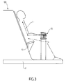
- a second bodybuilding machine 100 is shown.
- This machine 100 allows the localized work of the forearm of the user, for example the work of the supinator muscles.
- the user grasps the handles facing him, the palms of the hands down, thumbs inwards.
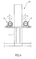
- the bodybuilding movement is simply about rotating about 180 °, against the preset force of the spring locked in the handle, thus bringing the thumbs outward (S-direction - phasic work).
- the return (tonic work) is done by resisting loosening of the turns.
- Another machine allows to work the pronator muscles.
- the handles are reversed.
- the grip is palms up and thumbs out.
- the movement consists of rotating about 180 ° inwards (P direction).
- the return is also done by resisting loosening of the turns.
- the handle is intrinsically a machine containing its own source of resistance to effort.
- the ball connecting the gripping bar 23 to the main body 21 allows ⁇ 20 ° rotation of said bar on any axis ZZ 'perpendicular to the main axis of rotation XX'.
- the combination of the rotation on the axis XX 'and the ball joint allows the wrist to describe a trajectory in double helix / spiral or in "8" (in one direction then in the other) which is a fluid movement and natural respecting human physiology.
- the section of the spring may be square, oval or rectangular and the latter may be steel, plastic or composite material.
- the shell can be made of molded composite material, stamped fine metal or metal alloy.
- the angle of rotation of the gripping bar in the shell may exceed 20 °.
- the rivets and screws may be replaced by other equivalent means of permanent or removable fasteners.
Landscapes
- Health & Medical Sciences (AREA)
- Orthopedic Medicine & Surgery (AREA)
- General Health & Medical Sciences (AREA)
- Physical Education & Sports Medicine (AREA)
- Life Sciences & Earth Sciences (AREA)
- Biophysics (AREA)
- Rehabilitation Tools (AREA)
Abstract
Description
La présente invention concerne une poignée destinée à être reliée à un système de résistance à une force, notamment par l'intermédiaire d'un câble ou d'une barre mobile, d'une machine de musculation et/ou de rééducation.The present invention relates to a handle intended to be connected to a force resistance system, in particular by means of a cable or a moving bar, a weight training machine and / or a re-education machine.
Actuellement, les appareils de musculation et/ou de rééducation physique de la partie haute du corps humain, notamment le torse et les bras, présentent globalement une structure rigide, ou bâti, comportant par exemple un banc ou un siège, un ou plusieurs système de résistance à une force, fonctionnant notamment à l'aide de poids réels ou virtuels (frottement, piston, ressorts ou autres moyens), de câbles, de poulies, de barres/leviers mobiles ou articulées et de poignées manuelles.At present, the bodybuilding and / or physical rehabilitation apparatus of the upper part of the human body, in particular the torso and the arms, generally have a rigid structure, or structure, comprising for example a bench or a seat, one or more resistance to a force, operating in particular using real or virtual weights (friction, piston, springs or other means), cables, pulleys, bars / levers movable or articulated and hand grips.
Or, ces poignées sont basiques, dans le sens où elles n'apportent aucune autre fonction que celle de faire office de moyen de préhension pour l'utilisateur. En simplifiant, il s'agit simplement de faire interface entre le(s) muscles(s) à faire travailler, par exemple les pectoraux, dorsaux, biceps, triceps, deltoïdes, et un système de résistance de la machine muni par exemple de contrepoids à soulever/laisser reposer alternativement.However, these handles are basic, in the sense that they provide no other function than that of acting as a means of grip for the user. Simplifying, it is simply an interface between the (s) muscles (s) to work, for example the pectorals, back, biceps, triceps, deltoid, and a resistance system of the machine provided for example counterweight lift / let stand alternately.
Ce type de machine, et donc de poignée, décrit notamment dans
Cependant, d'un point de vue ergonomie et efficacité, ces poignées ne sont pas du tout optimisées. Au contraire, du fait de leur forme, de la liaison qu'elles assurent entre le muscle à travailler et le système de résistance de la machine, les gestes effectués par l'utilisateurs peuvent provoquer des contraintes néfastes à l'entraînement ou à la rééducation dudit muscle. Des micro traumatismes peuvent donc survenir non seulement aux muscles mais également aux tendons ou à d'autres organes. Or, l'utilisation de ces machines est souvent basée sur la répétition d'un mouvement effectué plusieurs dizaines à centaines de fois. On comprendra donc aisément qu'il est indispensable d'améliorer ces poignées pour un meilleur confort d'utilisation et une meilleure efficacité des machines sur lesquelles elles sont montées.However, from an ergonomic and efficient point of view, these handles are not optimized at all. On the contrary, because of their shape, the link they provide between the muscle to work and the resistance system of the machine, the actions performed by the user can cause adverse constraints to training or rehabilitation said muscle. Micro traumas can occur not only to the muscles but also to the tendons or other organs. However, the use of these machines is often based on the repetition of a movement made several tens to hundreds of times. It is therefore easy to understand that it is essential to improve these handles for a better comfort of use and a better efficiency of the machines on which they are mounted.
Un but de la présente invention est donc de résoudre les problèmes cités précédemment à l'aide d'une solution simple à mettre en oeuvre, fiable et particulièrement ergonomique pour l'utilisateur.An object of the present invention is therefore to solve the problems mentioned above with a solution that is simple to implement, reliable and particularly ergonomic for the user.
Ainsi, la présente invention a pour objet une poignée destinée à être reliée à un système de résistance à une force, notamment par l'intermédiaire d'un câble ou d'un levier mobile, d'une machine de musculation et/ou de rééducation, ladite poignée comprenant un corps principal rigide auquel est relié un moyen de préhension manuelle, caractérisée en ce qu'elle comporte en outre un organe de rappel élastique reliant le moyen de préhension manuelle au corps principal et s'opposant à une force induite par un utilisateur se servant de la poigné pour faire fonctionner le système de résistance en déplaçant le moyen de préhension manuelle par rapport au corps principal.Thus, the present invention relates to a handle intended to be connected to a force resistance system, in particular by means of a cable or a mobile lever, a machine for weight training and / or rehabilitation, said handle comprising a rigid main body to which is connected a manual gripping means, characterized in that it further comprises a resilient return member connecting the manual gripping means to the main body and opposing a force induced by a user using the handle to operate the resistance system by moving the manual gripping means relative to the main body.
Selon des modes de réalisation préférés, la poignée selon la présente invention comprend en outre l'une au moins des caractéristiques suivantes :
- le moyen de préhension manuelle étant mobile en rotation à l'intérieur du corps principal selon un axe principal, l'organe de rappel élastique est adapté pour s'opposer à ladite rotation ;
- le corps principal comporte une coquille à cavité interne sensiblement hémisphérique, le moyen de préhension manuelle comporte une barre mobile disposée au niveau de l'ouverture de la coquille, au travers de celle-ci, et l'organe de rappel élastique s'étend dans la cavité, entre une partie de la barre et le fond de la coquille ;
- la barre est en outre articulée à l'intérieur de la coquille par une liaison rotule sphérique autour de tout axe secondaire perpendiculaire à l'axe principal de sorte que le mouvement du poignet de l'utilisateur peut décrire une spirale ;
- la barre mobile est liée à une couronne présentant des extrémités sphériques adaptées pour être logées dans un anneau à surface interne de forme complémentaire, ledit anneau étant fixé au corps principal ;
- l'organe de rappel élastique est un ressort hélicoïdal relié à la barre de préhension par l'intermédiaire d'une languette et dont les spires serpentent en spirale dans la cavité, en épousant sa surface ;
- le ressort hélicoïdal présente un coefficient de raideur en torsion déterminé et identique dans ses deux sens de torsion possible ;
- elle présente un moyen de réglage du coefficient de raideur en torsion du ressort hélicoïdal, ledit moyen étant accessible depuis l'extérieur de la coquille ;
- le ressort hélicoïdal est relié à une plaque de fond rendue solidaire du moyen de réglage ;
- le moyen de réglage comporte un bouton mobile en translation et rotation et lié à la plaque de fond de manière à pouvoir agir sur la raideur du ressort hélicoïdal en resserrant ou relâchant ses spires les unes des autres ;
- la section des spires du ressort hélicoïdal est ronde ;
- le ressort hélicoïdal est bloqué en rotation d'une part par une goupille adaptée pour pénétrer dans une cavité de la coquille, au niveau d'un côté proche du fond de la cavité, et d'autre part par un rivet relié à la languette ;
- la couronne est en métal, l'anneau est en matière plastique ; et
- le moyen de préhension manuelle est mobile en rotation autour de l'axe secondaire selon un angle α d'environ ±20° par rapport à une position initiale de repos.
- the manual gripping means being movable in rotation inside the main body along a main axis, the elastic return member is adapted to oppose said rotation;
- the main body comprises a substantially hemispherical inner-cavity shell, the manual gripping means comprises a movable bar disposed at the opening of the shell, through it, and the elastic return member extends into the cavity, between a part of the bar and the bottom of the shell;
- the bar is further articulated inside the shell by a spherical ball joint connection about any secondary axis perpendicular to the main axis so that the movement of the wrist of the user can describe a spiral;
- the movable bar is connected to a ring having spherical ends adapted to be housed in a ring with internal surface of complementary shape, said ring being fixed to the main body;
- the elastic return member is a helical spring connected to the gripping bar by means of a tongue and whose turns wind spirally in the cavity, marrying its surface;
- the helical spring has a coefficient of torsional stiffness determined and identical in its two possible directions of torsion;
- it has a means for adjusting the torsional stiffness coefficient of the helical spring, said means being accessible from outside the shell;
- the coil spring is connected to a bottom plate secured to the adjusting means;
- the adjusting means comprises a button movable in translation and rotation and connected to the base plate so as to act on the stiffness of the coil spring by tightening or loosening its turns from each other;
- the coil section of the coil spring is round;
- the helical spring is locked in rotation on the one hand by a pin adapted to penetrate into a cavity of the shell, at a side near the bottom of the cavity, and secondly by a rivet connected to the tongue;
- the crown is metal, the ring is plastic; and
- the manual gripping means is rotatable about the secondary axis at an angle α of about ± 20 ° with respect to an initial rest position.
La présente invention se rapporte également à une machine de musculation et/ou de rééducation comportant un système de résistance à une force relié à au moins une poignée telle que décrite précédemment.The present invention also relates to a weight training and / or rehabilitation machine comprising a force resistance system connected to at least one handle as described above.
L'invention va maintenant être décrite plus en détail en référence à un mode de réalisation particulier donné à titre d'illustration et représentés sur les figures dans lesquelles :
- la
figure 1 est une vue de face d'une première machine de musculation sur laquelle sont montées deux poignées conformes à la présente invention ; - la
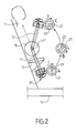
figure 2 est une vue de côté de ladite machine ; - la
figure 3 est une vue de côté d'une seconde machine ; - la
figure 4 est une vue de face de lafigure 3 ; - la
figure 5 est une vue de détail en coupe de la poignée ; et - la
figure 6 est une vue en coupe de la poignée en utilisation.
- the
figure 1 is a front view of a first weight machine on which are mounted two handles according to the present invention; - the
figure 2 is a side view of said machine; - the
figure 3 is a side view of a second machine; - the
figure 4 is a front view of thefigure 3 ; - the
figure 5 is a detail view in section of the handle; and - the
figure 6 is a sectional view of the handle in use.
La
Comme cela est schématisé, cette machine 10 comporte un bâti métallique rigide 11 entre les montants 12 duquel un utilisateur 1 peut s'asseoir sur un siège 13. Chaque montant 12 du bâti 11 supporte des contrepoids 14 reliés à des câbles 15 coopérant avec des poulies 16. Chaque câble est relié à un levier articulé 17 auquel est fixée une poignée 20 conforme à la présente invention.As shown schematically, this
La poignée 20 est également représentée seule sur la
Cette poignée 20 comprend un corps principal rigide 21 formant une coquille réalisée par exemple en matière plastique et comportant une cavité sensiblement hémisphérique 22. La cavité 22 présente une ouverture 22a, une surface interne 22b et un axe principal de symétrie XX'.This
Un moyen de préhension manuelle 23, tel qu'une barre de section ronde, s'étend de manière diamétrale en travers de l'ouverture 22a. Cette barre 23 est rendue solidaire d'une couronne interne métallique 24, par exemple par soudure, présentant surface périphérique externe 24a en forme de portion de sphère coopérant avec la surface interne 25a d'une anneau périphérique 25 réalisé en matière plastique et monté par exemple à force dans la cavité hémisphérique 22. La collaboration de la couronne interne 24 et de l'anneau périphérique 25 forme une liaison rotule sphérique permettant à la barre de préhension 23 de pivoter sur un angle α mesurant ±20°, par rapport à une position initiale de repos, au regard du corps principal 21, cette rotation se faisant selon tout axe ZZ' perpendiculaire à l'axe principal XX'.A manual gripping means 23, such as a round section bar, extends diametrically across the opening 22a. This
A cet effet, l'anneau périphérique 25 est de réalisé dans une matière plastique ayant qualité de dureté et de glissement permettant à la barre 23 de pivoter en toute liberté, avec des frottements limités.For this purpose, the
Un organe de rappel élastique 30, tel qu'un ressort hélicoïdal de torsion 31, relie la barre de préhension 23 au corps principal 21. Plus précisément, un ressort hélicoïdal 31 à spires 32 de section rondes s'étend dans la cavité hémisphérique 22, entre une languette de fixation 33 solidaire de la barre de préhension 23 et une plaque de fond 34 à laquelle il est soudé. Le ressort 31 est fixé à la languette 33 par un rivet 35. Les spires 32 du ressort hélicoïdal 31 serpentent en spirale et épousent la surface interne 22b de la cavité hémisphérique 22. Le ressort hélicoïdal 31 présente un coefficient de raideur en torsion déterminé et identique dans ses deux sens de torsion possible.An
Un moyen de réglage 36 de la raideur du ressort hélicoïdal 31, accessible depuis l'extérieur de la poignée 20, est prévu au niveau du sommet 21b de la coquille 21. Ce moyen 36 se présente sous la forme d'un bouton 37 mobile en translation (flèche TR) et rotation (flèche R) lié à la plaque fond 34 à l'aide de vis 38 de manière à pouvoir agir sur la raideur du ressort hélicoïdal 31 en resserrant ou relâchant ses spires 32. Une fois la raideur déterminée, le bouton 37 est bloqué dans la position choisie par l'intermédiaire d'une goupille 39 pénétrant dans une cavité 40 du corps principal 21.An adjustment means 36 of the stiffness of the
Le corps principal 21 de la poignée 20 est rendu solidaire du levier 17 par l'intermédiaire d'un cerclage 42 présentant localement un logement 44 recevant l'extrémité dudit levier et appartenant à un fourreau 43. Une goupille 45 est également prévue pour relier transitoirement le ressort 31 à la coquille 21 par l'intermédiaire du cerclage 42 afin d'empêcher la rotation de la poignée 20 lors du réglage de la raideur du ressort.The
Le fonctionnement de la poignée 20 est le suivant.The operation of the
Au repos, la poignée 20 est par exemple en position basse, comme cela est illustré sur la partie gauche de la
Lorsque l'utilisateur tire sur la poignée 20 de manière à faire pivoter la tige 17 sur son axe YY' vers le haut (Cf. partie droite de la
Dans ce cas, la main attrape la poignée en position neutre, pouce vers l'avant. Le mouvement consiste alors à faire une rotation de l'avant bras, simultanément à sa remontée, de manière à amener les mains en supination, c'est-à-dire pouces vers l'extérieur. C'est ce que m'on appelle le travail phasique. Cette rotation se fait contre la résistance du ressort 31 engagé dans le corps principal hémisphérique 21 et dont l'enroulement des spires 32 est forcément inverse au mouvement. Le retour à la position de départ (travail tonique), c'est-à-dire l'abaissement de l'avant bras, se fait aussi contre la résistance du ressort 31 qui tend à reprendre sa position initiale.In this case, the hand catches the handle in the neutral position, inch forward. The movement then consists in turning the forearm simultaneously with its ascent, so as to bring the hands supinated, that is to say, inches outwards. This is called phasic work. This rotation is against the resistance of the
Comme cela est schématisé sur la
Sur les
Une autre machine (même représentation) permet de travailler les muscles pronateurs. Dans ce cas, les poignées sont inversées. La prise en main se fait paumes vers le haut et pouces vers l'extérieur. Le mouvement consiste à effectuer une rotation d'environ 180° vers l'intérieur (sens P). Le retour se fait également en résistant au relâchement des spires.Another machine (same representation) allows to work the pronator muscles. In this case, the handles are reversed. The grip is palms up and thumbs out. The movement consists of rotating about 180 ° inwards (P direction). The return is also done by resisting loosening of the turns.
Dans ces deux cas, la poignée constitue intrinsèquement une machine contenant sa propre source de résistance à l'effort.In both cases, the handle is intrinsically a machine containing its own source of resistance to effort.
Dans tous les cas représentés, la rotule reliant la barre de préhension 23 au corps principal 21 permet une rotation sur ±20° de ladite barre sur tout axe ZZ' perpendiculaire à l'axe principal de rotation XX'.In all cases shown, the ball connecting the gripping
Ainsi, la combinaison de la rotation sur l'axe XX' et de la liaison rotule permet au poignet de décrire une trajectoire en double hélice/spirale ou en « 8 » (dans un sens puis dans l'autre) qui est un mouvement fluide et naturel respectant la physiologie humaine.Thus, the combination of the rotation on the axis XX 'and the ball joint allows the wrist to describe a trajectory in double helix / spiral or in "8" (in one direction then in the other) which is a fluid movement and natural respecting human physiology.
En conclusion, l'importance des avantages procurés par la présente invention doit s'étendre à l'ensemble des machines de musculation ou de rééducation pour le haut du corps et ne pas se limiter aux deux cas donnés à titre d'exemple.In conclusion, the importance of the benefits provided by the present invention should extend to all bodybuilding or rehabilitation equipment for the upper body and not be limited to the two cases given by way of example.
Le risque de microtraumatismes lors de l'utilisation d'une machine de musculation du haut du corps (pectoraux, dorsaux, épaules, bas, avant-bras) est donc considérablement réduit voire inexistant. En effet, la main n'étant plus prisonnière d'une structure de préhension rigide et fixe, la force qu'elle induit, quel que soit le mouvement effectué, s'oppose plus naturellement au système de résistance de la machine. En plus du fait que ce mouvement biologiquement naturel évite les micro traumatismes, en préservant la proprioceptivité de la chaîne articulaire qui travaille, la force de résistance élastique du ressort de la poignée permet d'optimiser l'effort (travail de la musculation ou de rééducation).The risk of microtrauma when using an upper body weight training machine (chest, back, shoulders, lower, forearm) is therefore considerably reduced or non-existent. Indeed, the hand is no longer trapped in a rigid and fixed gripping structure, the force it induces, regardless of the movement performed, more naturally opposes the resistance system of the machine. In addition to the fact that this biologically natural movement avoids micro traumas, preserving the proprioceptivity of the articular chain that works, the elastic resistance force of the spring of the handle makes it possible to optimize the effort (work of the bodybuilding or of reeducation ).
Il va de soi que la description détaillée de l'objet de l'Invention, donnée uniquement à titre d'illustration, ne constitue en aucune manière une limitation, les équivalents techniques étant également compris dans le champ de la présente invention.It goes without saying that the detailed description of the subject of the invention, given solely by way of illustration, does not constitute in no way a limitation, the technical equivalents also being within the scope of the present invention.
Ainsi, la section du ressort peut être carrée, ovale ou rectangulaire et ce dernier peut être en acier, en plastique ou en matériau composite.Thus, the section of the spring may be square, oval or rectangular and the latter may be steel, plastic or composite material.
La coquille peut être réalisée en matériau composite moulé, en métal fin embouti ou en alliage métallique.The shell can be made of molded composite material, stamped fine metal or metal alloy.
L'angle de rotation de la barre de préhension dans la coquille peut dépasser les 20°.The angle of rotation of the gripping bar in the shell may exceed 20 °.
Les rivets et vis peuvent être remplacés par d'autres moyens équivalents de fixation définitifs ou amovibles.The rivets and screws may be replaced by other equivalent means of permanent or removable fasteners.
Claims (15)
Priority Applications (1)
| Application Number | Priority Date | Filing Date | Title |
|---|---|---|---|
| EP08306015A EP2201986A1 (en) | 2008-12-24 | 2008-12-24 | Handle designed to be connected to a system for resisting a force of a bodybuilding and/or re-education machine |
Applications Claiming Priority (1)
| Application Number | Priority Date | Filing Date | Title |
|---|---|---|---|
| EP08306015A EP2201986A1 (en) | 2008-12-24 | 2008-12-24 | Handle designed to be connected to a system for resisting a force of a bodybuilding and/or re-education machine |
Publications (1)
| Publication Number | Publication Date |
|---|---|
| EP2201986A1 true EP2201986A1 (en) | 2010-06-30 |
Family
ID=40608677
Family Applications (1)
| Application Number | Title | Priority Date | Filing Date |
|---|---|---|---|
| EP08306015A Withdrawn EP2201986A1 (en) | 2008-12-24 | 2008-12-24 | Handle designed to be connected to a system for resisting a force of a bodybuilding and/or re-education machine |
Country Status (1)
| Country | Link |
|---|---|
| EP (1) | EP2201986A1 (en) |
Cited By (1)
| Publication number | Priority date | Publication date | Assignee | Title |
|---|---|---|---|---|
| CN114247102A (en) * | 2021-12-23 | 2022-03-29 | 黄尾莲 | Arm muscle tension training device for rehabilitation department |
Citations (4)
| Publication number | Priority date | Publication date | Assignee | Title |
|---|---|---|---|---|
| SU1289516A1 (en) * | 1985-08-28 | 1987-02-15 | Белорусский Государственный Институт Физической Культуры | Apparatus for training foot muscles |
| FR2623720A1 (en) | 1987-03-26 | 1989-06-02 | Seignolles Jean | Muscle-development apparatus |
| US6387023B1 (en) * | 2000-05-30 | 2002-05-14 | Donald Liga, Jr. | Multiple effect exercising device |
| US20040082448A1 (en) * | 2002-10-24 | 2004-04-29 | Martin Joseph G. | Ergonomic handle |
-
2008
- 2008-12-24 EP EP08306015A patent/EP2201986A1/en not_active Withdrawn
Patent Citations (4)
| Publication number | Priority date | Publication date | Assignee | Title |
|---|---|---|---|---|
| SU1289516A1 (en) * | 1985-08-28 | 1987-02-15 | Белорусский Государственный Институт Физической Культуры | Apparatus for training foot muscles |
| FR2623720A1 (en) | 1987-03-26 | 1989-06-02 | Seignolles Jean | Muscle-development apparatus |
| US6387023B1 (en) * | 2000-05-30 | 2002-05-14 | Donald Liga, Jr. | Multiple effect exercising device |
| US20040082448A1 (en) * | 2002-10-24 | 2004-04-29 | Martin Joseph G. | Ergonomic handle |
Cited By (2)
| Publication number | Priority date | Publication date | Assignee | Title |
|---|---|---|---|---|
| CN114247102A (en) * | 2021-12-23 | 2022-03-29 | 黄尾莲 | Arm muscle tension training device for rehabilitation department |
| CN114247102B (en) * | 2021-12-23 | 2023-08-08 | 南京市蓝业科技有限公司 | Arm muscle tension training device for rehabilitation department |
Similar Documents
| Publication | Publication Date | Title |
|---|---|---|
| US20110177922A1 (en) | Exercise Barbell | |
| US20150217156A1 (en) | Assisted chin/dip exercise apparatus with adjustable chin-up/pull-up handles | |
| US9168416B2 (en) | Abdomen exercise machine | |
| US9101792B2 (en) | Abdomen exercise machine | |
| US20180056120A1 (en) | Multi-Purpose Resistance-Free Exercise Wheel | |
| US20150174497A1 (en) | Playground swing and method of swinging | |
| CA3093690A1 (en) | Flip and grip handle system for lateral pulldown exercise machine | |
| US6234942B1 (en) | Compound exerciser unit | |
| EP2201986A1 (en) | Handle designed to be connected to a system for resisting a force of a bodybuilding and/or re-education machine | |
| FR2972340A1 (en) | Sensor device for use in rehabilitation apparatus for exercising shoulders of body of e.g. sportsman in gym, has sleeve including sensors, each comprising strain gauge to measure force exerted on handle of apparatus | |
| FR2821276A3 (en) | MACHINE FOR EXERCISING PHYSICS | |
| KR101223194B1 (en) | Exercise apparatus | |
| FR2498934A1 (en) | HALTEROPHILIA MACHINE FOR PHYSICAL CONDITIONING | |
| FR2899119A3 (en) | Exercise ball comprises inflated toroidal tube which encloses a central transverse aperture of smaller diameter than that of tube | |
| FR3079423A1 (en) | MUSCULATION TOOL | |
| US20140274621A1 (en) | Rehabilitation or exercising chair device | |
| US11992724B1 (en) | Cable handles | |
| BE1015585A3 (en) | Exercise equipment. | |
| WO2018073501A1 (en) | Modifiable floating dumbbell for use during water activities | |
| EP0060798A1 (en) | Muscle exercise apparatus | |
| EP2702971B1 (en) | Wheelchair equipped with muscular training members | |
| CA2545887C (en) | Rowing oar handle | |
| WO2022101888A1 (en) | General bodybuilding apparatus | |
| CA2525888C (en) | Prosthetic device for golfing | |
| WO2008102381A1 (en) | Machine for exercising the pectoral muscles |
Legal Events
| Date | Code | Title | Description |
|---|---|---|---|
| PUAI | Public reference made under article 153(3) epc to a published international application that has entered the european phase |
Free format text: ORIGINAL CODE: 0009012 |
|
| AK | Designated contracting states |
Kind code of ref document: A1 Designated state(s): AT BE BG CH CY CZ DE DK EE ES FI FR GB GR HR HU IE IS IT LI LT LU LV MC MT NL NO PL PT RO SE SI SK TR |
|
| AX | Request for extension of the european patent |
Extension state: AL BA MK RS |
|
| 17P | Request for examination filed |
Effective date: 20101211 |
|
| AKX | Designation fees paid |
Designated state(s): AT BE BG CH CY CZ DE DK EE ES FI FR GB GR HR HU IE IS IT LI LT LU LV MC MT NL NO PL PT RO SE SI SK TR |
|
| 17Q | First examination report despatched |
Effective date: 20110512 |
|
| GRAP | Despatch of communication of intention to grant a patent |
Free format text: ORIGINAL CODE: EPIDOSNIGR1 |
|
| INTG | Intention to grant announced |
Effective date: 20141105 |
|
| STAA | Information on the status of an ep patent application or granted ep patent |
Free format text: STATUS: THE APPLICATION HAS BEEN WITHDRAWN |
|
| 18W | Application withdrawn |
Effective date: 20150304 |