EP2201311B1 - System and method for cooling structures having both an active state and an inactive state - Google Patents
System and method for cooling structures having both an active state and an inactive state Download PDFInfo
- Publication number
- EP2201311B1 EP2201311B1 EP08798833.3A EP08798833A EP2201311B1 EP 2201311 B1 EP2201311 B1 EP 2201311B1 EP 08798833 A EP08798833 A EP 08798833A EP 2201311 B1 EP2201311 B1 EP 2201311B1
- Authority
- EP
- European Patent Office
- Prior art keywords
- heat
- fluid coolant
- generating structure
- temperature
- inactive
- Prior art date
- Legal status (The legal status is an assumption and is not a legal conclusion. Google has not performed a legal analysis and makes no representation as to the accuracy of the status listed.)
- Active
Links
- 238000001816 cooling Methods 0.000 title claims description 91
- 238000000034 method Methods 0.000 title claims description 13
- 239000012530 fluid Substances 0.000 claims description 142
- 239000002826 coolant Substances 0.000 claims description 138
- 238000004891 communication Methods 0.000 claims description 5
- 239000007788 liquid Substances 0.000 claims description 3
- 238000010586 diagram Methods 0.000 description 10
- 230000007423 decrease Effects 0.000 description 7
- 238000012546 transfer Methods 0.000 description 7
- 230000008901 benefit Effects 0.000 description 5
- 239000007791 liquid phase Substances 0.000 description 5
- 238000003491 array Methods 0.000 description 4
- 238000007796 conventional method Methods 0.000 description 4
- 230000020169 heat generation Effects 0.000 description 4
- 230000035939 shock Effects 0.000 description 4
- XLYOFNOQVPJJNP-UHFFFAOYSA-N water Substances O XLYOFNOQVPJJNP-UHFFFAOYSA-N 0.000 description 4
- LYCAIKOWRPUZTN-UHFFFAOYSA-N Ethylene glycol Chemical compound OCCO LYCAIKOWRPUZTN-UHFFFAOYSA-N 0.000 description 3
- OKKJLVBELUTLKV-UHFFFAOYSA-N Methanol Chemical compound OC OKKJLVBELUTLKV-UHFFFAOYSA-N 0.000 description 3
- DNIAPMSPPWPWGF-UHFFFAOYSA-N Propylene glycol Chemical compound CC(O)CO DNIAPMSPPWPWGF-UHFFFAOYSA-N 0.000 description 3
- 238000010521 absorption reaction Methods 0.000 description 3
- 230000002528 anti-freeze Effects 0.000 description 3
- 230000007613 environmental effect Effects 0.000 description 3
- 239000002184 metal Substances 0.000 description 3
- 239000000203 mixture Substances 0.000 description 3
- 239000012808 vapor phase Substances 0.000 description 3
- QGZKDVFQNNGYKY-UHFFFAOYSA-N Ammonia Chemical compound N QGZKDVFQNNGYKY-UHFFFAOYSA-N 0.000 description 2
- LFQSCWFLJHTTHZ-UHFFFAOYSA-N Ethanol Chemical compound CCO LFQSCWFLJHTTHZ-UHFFFAOYSA-N 0.000 description 2
- 230000003213 activating effect Effects 0.000 description 2
- 230000004075 alteration Effects 0.000 description 2
- 239000000110 cooling liquid Substances 0.000 description 2
- 230000036541 health Effects 0.000 description 2
- 238000005259 measurement Methods 0.000 description 2
- 238000012986 modification Methods 0.000 description 2
- 230000004048 modification Effects 0.000 description 2
- 229920013639 polyalphaolefin Polymers 0.000 description 2
- 238000005057 refrigeration Methods 0.000 description 2
- 230000009466 transformation Effects 0.000 description 2
- LVGUZGTVOIAKKC-UHFFFAOYSA-N 1,1,1,2-tetrafluoroethane Chemical compound FCC(F)(F)F LVGUZGTVOIAKKC-UHFFFAOYSA-N 0.000 description 1
- -1 Coolanol Chemical compound 0.000 description 1
- 229910021529 ammonia Inorganic materials 0.000 description 1
- 239000012267 brine Substances 0.000 description 1
- 230000008859 change Effects 0.000 description 1
- 230000001143 conditioned effect Effects 0.000 description 1
- 230000003247 decreasing effect Effects 0.000 description 1
- 238000003745 diagnosis Methods 0.000 description 1
- 238000006073 displacement reaction Methods 0.000 description 1
- 239000004973 liquid crystal related substance Substances 0.000 description 1
- 238000013021 overheating Methods 0.000 description 1
- 238000005192 partition Methods 0.000 description 1
- 239000012071 phase Substances 0.000 description 1
- 238000004393 prognosis Methods 0.000 description 1
- 230000009467 reduction Effects 0.000 description 1
- 239000003507 refrigerant Substances 0.000 description 1
- 230000000630 rising effect Effects 0.000 description 1
- 238000000926 separation method Methods 0.000 description 1
- HPALAKNZSZLMCH-UHFFFAOYSA-M sodium;chloride;hydrate Chemical compound O.[Na+].[Cl-] HPALAKNZSZLMCH-UHFFFAOYSA-M 0.000 description 1
- 239000000243 solution Substances 0.000 description 1
- 238000000638 solvent extraction Methods 0.000 description 1
- 238000000844 transformation Methods 0.000 description 1
Images

Classifications
-
- F—MECHANICAL ENGINEERING; LIGHTING; HEATING; WEAPONS; BLASTING
- F25—REFRIGERATION OR COOLING; COMBINED HEATING AND REFRIGERATION SYSTEMS; HEAT PUMP SYSTEMS; MANUFACTURE OR STORAGE OF ICE; LIQUEFACTION SOLIDIFICATION OF GASES
- F25B—REFRIGERATION MACHINES, PLANTS OR SYSTEMS; COMBINED HEATING AND REFRIGERATION SYSTEMS; HEAT PUMP SYSTEMS
- F25B23/00—Machines, plants or systems, with a single mode of operation not covered by groups F25B1/00 - F25B21/00, e.g. using selective radiation effect
- F25B23/006—Machines, plants or systems, with a single mode of operation not covered by groups F25B1/00 - F25B21/00, e.g. using selective radiation effect boiling cooling systems
-
- F—MECHANICAL ENGINEERING; LIGHTING; HEATING; WEAPONS; BLASTING
- F28—HEAT EXCHANGE IN GENERAL
- F28D—HEAT-EXCHANGE APPARATUS, NOT PROVIDED FOR IN ANOTHER SUBCLASS, IN WHICH THE HEAT-EXCHANGE MEDIA DO NOT COME INTO DIRECT CONTACT
- F28D15/00—Heat-exchange apparatus with the intermediate heat-transfer medium in closed tubes passing into or through the conduit walls ; Heat-exchange apparatus employing intermediate heat-transfer medium or bodies
-
- H—ELECTRICITY
- H01—ELECTRIC ELEMENTS
- H01Q—ANTENNAS, i.e. RADIO AERIALS
- H01Q1/00—Details of, or arrangements associated with, antennas
- H01Q1/02—Arrangements for de-icing; Arrangements for drying-out ; Arrangements for cooling; Arrangements for preventing corrosion
-
- H—ELECTRICITY
- H05—ELECTRIC TECHNIQUES NOT OTHERWISE PROVIDED FOR
- H05K—PRINTED CIRCUITS; CASINGS OR CONSTRUCTIONAL DETAILS OF ELECTRIC APPARATUS; MANUFACTURE OF ASSEMBLAGES OF ELECTRICAL COMPONENTS
- H05K7/00—Constructional details common to different types of electric apparatus
- H05K7/20—Modifications to facilitate cooling, ventilating, or heating
- H05K7/20218—Modifications to facilitate cooling, ventilating, or heating using a liquid coolant without phase change in electronic enclosures
- H05K7/20281—Thermal management, e.g. liquid flow control
Definitions
- cooling systems may be used to cool commercial and military applications. Although these cooling systems may minimize a need for conditioned air, they may be limited by the amount of structures being cooled and the current state of each structure (i.e. active, inactive, standby).
- a fluid coolant flows through each of the structure heat exchangers 23, 24.
- the fluid coolant absorbs heat from the structure 12.
- the structure heat exchangers 23, 24 may be lined with pin fins or other similar devices which, among other things, increase surface contact between the fluid coolant and walls of the structure heat exchangers 23, 24.
- the fluid coolant may be forced or sprayed into the structure heat exchangers 23, 24 to ensure fluid contact between the fluid coolant and the walls of the structure heat exchangers 23, 24.
- the fluid coolant may remain in a liquid phase after absorption of heat from the structure 12.
- the absorption of heat from the structure 12 may cause at least a portion of the fluid coolant to vaporize.
Landscapes
- Engineering & Computer Science (AREA)
- Physics & Mathematics (AREA)
- Thermal Sciences (AREA)
- Microelectronics & Electronic Packaging (AREA)
- Mechanical Engineering (AREA)
- General Engineering & Computer Science (AREA)
- Cooling Or The Like Of Electrical Apparatus (AREA)
Description
- This invention relates generally to the field of cooling systems and, more particularly, to a system and method for cooling structures having both an active state and an inactive state.
- A variety of different types of structures can generate heat or thermal energy in operation. To prevent such structures from over heating, a variety of different types of cooling systems may be utilized to dissipate the thermal energy. The ability to cool may be limited, however, by the amount of structures needing to be cooled and the current state of each structure (i.e. active, inactive, standby).
-
US 6205803 discloses a method and apparatus for compact thermal control of avionics pod cooling units, wherein refrigerant is circulated through a plate of an avionics pod in a closed loop system. The plate can serve as an evaporator in a heat pump or a heat exchange in a pumped coolant loop. -
US 2003/0140638 discloses a cooling system for heat generating structures comprising a cooling loop and a heat exchanger. -
US 2002/101716 A1 discloses a liquid-cooling system for a notebook personal computer having a body part including a CPU and a chip set respectively mounted on a mother board and an HDD, and a display part rotatably supported by the body part. A heat receiving head is fixed to at least one heat generation part including the CPU. A tube filled with cooling liquid is connected to the heat receiving head. The tube connected to the heat receiving head is disposed in series on at least one heat generation part including the chip set so as to collect the heat generated from each heat generation part. The tube is also laid in a meandering or zigzagging pattern between a liquid crystal panel and a housing of the display part. The heat generated from each heat generation part is absorbed at part of the tube by the cooling liquid that circulates in the tube and functions as a heat transfer medium. The absorbed heat is then radiated at another part of the tube. Consequently, the heat generated from the chip set including the CPU and other heat sources such as the HDD can be radiated together to the outside. Local temperature rising is prevented. A uniform temperature environment is attained on all surfaces of the body part. - According to one aspect of the invention there is provided a system for cooling heat-generating structures according to claim 1.
- According to another aspect of the invention there is provided a method for cooling heat generating structures according to claim 8.
- A technical advantage of the invention includes the capability to prevent the thermal shock associated with activating a previously inactive structure. For example, the same fluid coolant used to cool an active structure may also be used to heat an inactive structure, keeping the inactive structure at an optimum working temperature. Other technical advantages of other embodiments may include the capability to cool a phased array antenna located on a mast of a ship. Still yet other technical advantages of other embodiments may include the capability to use sensors to measure the health of a cooling system.
- For a more complete understanding of example embodiments of the present invention and its advantages, reference is now made to the following description, taken in conjunction with the accompanying drawings, in which:
-
FIGURE 1 is a block diagram of a cooling system that may be utilized in conjunction with embodiments of the present invention; -
FIGURE 2 is a diagram of a system with more than one structure needing to be cooled; -
FIGURE 3 is a block diagram of a cooling system that may cool more than one heat-generating structure; -
FIGURE 4 is a block diagram of a cooling system that may cool more than one heat-generating structure; and -
FIGURE 5 is a block diagram of a cooling system according to the invention that may cool more than one heat-generating structure. - It should be understood at the outset that although example embodiments of the present invention are illustrated below, the present invention may be implemented using any number of techniques, whether currently known or in existence. The present invention should in no way be limited to the example embodiments, drawings, and techniques illustrated below, including the embodiments and implementation illustrated and described herein. Additionally, the drawings are not necessarily drawn to scale.
- Conventionally, cooling systems may be used to cool commercial and military applications. Although these cooling systems may minimize a need for conditioned air, they may be limited by the amount of structures being cooled and the current state of each structure (i.e. active, inactive, standby).
-
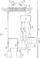
FIGURE 1 is a block diagram of an illustrative example of a cooling system that may be utilized in conjunction with embodiments of the present invention. Although the details of one cooling system will be described below, it should be expressly understood that other cooling systems may be used in conjunction with embodiments of the invention. - The
cooling system 10 ofFIGURE 1 is shown cooling astructure 12 that is exposed to or generates thermal energy. Thestructure 12 may be any of a variety of structures, including, but not limited to, electronic components, circuits, computers, servers, and arrays of a phased array antenna. Because thestructure 12 can vary greatly, the details ofstructure 12 are not illustrated and described. Thecooling system 10 ofFIGURE 1 includes a heatexchanger inlet line 61, astructure inlet line 71,structure heat exchangers loop pump 46,inlet orifices 47 and 48, aheat exchanger 41 , areservoir 42, and apressure controller 51. - The
structure 12 may be arranged and designed to conduct heat or thermal energy to thestructure heat exchangers structure heat exchangers structure 12, for example, through a thermal plane of thestructure 12. In particular embodiments, thestructure heat exchangers structure 12, directly receiving thermal energy from the components. Although twostructure heat exchangers cooling system 10 ofFIGURE 1 , one structure heat exchanger or more than two structure heat exchangers may be used to cool thestructure 12 in other cooling systems. - In operation, a fluid coolant flows through each of the
structure heat exchangers structure 12. To facilitate
such absorption or transfer of thermal energy, thestructure heat exchangers structure heat exchangers structure heat exchangers structure heat exchangers structure 12. In a further embodiment, the absorption of heat from thestructure 12 may cause at least a portion of the fluid coolant to vaporize. - The fluid coolant departs the
exit conduits 27 and flows through the heatexchanger inlet line 61, theheat exchanger 41, thereservoir 42, aloop pump 46, thestructure inlet line 71, and a respective one of twoorifices 47 and 48, in order to again reach theinlet conduits 25 of thestructure heat exchangers loop pump 46 may cause the fluid coolant to circulate around the loop shown inFIGURE 1 . In particular embodiments, theloop pump 46 may use magnetic drives so there are no shaft seals that can wear or leak with time. In one embodiment, theloop pump 46 may control the mass flow rate of the fluid coolant in the loop. For example, theloop pump 46 may increase, decrease, or keep the mass flow rate of the fluid coolant constant. - The
orifices 47 and 48, in particular embodiments, may facilitate proper partitioning of the fluid coolant among the respectivestructure heat exchangers loop pump 46 and theheat exchangers orifices 47 and 48 may have the same size, or may have different sizes in order to partition the coolant in a proportional manner which facilitates a desired cooling profile. - A
flow 56 of fluid (either gas or liquid) may be forced to flow through theheat exchanger 41, for example by a fan (not shown) or other suitable device. In particular embodiments, theflow 56 of fluid may be ambient fluid. Theheat exchanger 41 transfers heat from the fluid coolant to theflow 56 of ambient fluid, thereby reducing the temperature of the fluid coolant. In one embodiment, the fluid coolant may be in a liquid phase prior to entering theheat exchanger 41. In this embodiment, the transfer of heat to theflow 56 may not cause the fluid coolant to change phases. In another embodiment, at least a portion of the fluid coolant may be in a vapor phase prior to entering theheat exchanger 41. In such an embodiment, the transfer of heat from the vapor fluid coolant to theflow 56 may further cause the fluid coolant to condense into a liquid phase. - The fluid coolant exiting the
heat exchanger 41 may be supplied to thereservoir 42. In one embodiment, thereservoir 42 may store the fluid coolant when thecooling system 10 is not in operation. In a further embodiment, thereservoir 42 may be an expansion reservoir. Since fluids typically take up more volume in their vapor phase than in their liquid phase, the expansion reservoir may be provided in order to take up the volume of liquid fluid coolant that is displaced when some or all of the coolant in the system changes from its liquid phase to its vapor phase. - The fluid coolant used in the embodiment of
FIGURE 1 may include, but is not limited to, mixtures of antifreeze and water or water, alone. In particular embodiments, the antifreeze may be ethanol, methanol, or other suitable antifreeze. In other embodiments, the fluid coolant may include polyalphaolefin (PAO), a mixture of water and propylene glycol (PGW), a mixture of water and ethylene glycol (EGW), HFC-134a, Coolanol, ammonia, brine, or any other suitable fluid coolant. - The
pressure controller 51 maintains the fluid coolant at a substantially constant pressure along the portion of the loop which extends from theorifices 47 and 48 to theloop pump 46, in particular through thestructure heat exchangers heat exchanger 41, and thereservoir 42. In particular embodiments, metal bellows may be used in thereservoir 42, connected to the loop using brazed joints. In particular embodiments, thepressure controller 51 may control loop pressure by using a motor driven linear actuator that is part of the metal bellows of thereservoir 42, or by using a small gear pump to evacuate the loop to the desired pressure level. The fluid coolant removed may be stored in the metal bellows whose fluid connects are brazed. In other configurations, thepressure controller 51 may utilize other suitable devices capable of controlling pressure. - It will be noted that the embodiment of
FIGURE 1 may operate without a refrigeration system. In the context of electronic circuitry, such as may be utilized in thestructure 12, the absence of a refrigeration system can result in a significant reduction in the size, weight, and power consumption of the structure provided to cool the circuit components of thestructure 12. - In particular embodiments of a cooling system, more than one structure may need to be cooled. For example, cooling may be required for more than one server, or more than one array of a phased array antenna. In a further embodiment, a structure may not be in use at all times. For example, there may be times when a structure, such as an array of a phased array antenna, is turned off, or placed in a standby mode. As a result, the structure may not be exposed to, or may not be generating thermal energy. Therefore, the structure may not need to be cooled while not in use.
-
FIGURE 2 is a diagram of an illustrative example of asystem 100 with more than one structure needing to be cooled. According to the illustrated example,system 100 includesstructures 112a-d. - The structures 112 may be substantially similar to the
structure 12 ofFIGURE 1 . For example, the structures 112 may be any of a variety of structures, including, but not limited to, electronic components, circuits, computers, servers, and arrays of a phased array antenna. In one embodiment, each of thestructures 112a-d may be the same type of structure. For example, each of thestructures 112a-d may be a computer. In a further embodiment, one or more of thestructures 112a-d may be a different type of structure. For example, thestructure 112a may be a computer while thestructure 112b may be a circuit. - According to the illustrated embodiment, the structures 112
face directions 114a-d. As illustrated, thedirections 114a-d may each be a different direction. In such an embodiment, thestructures 112a-d may each face a different direction 114. As illustrated, thedirection 114a and thedirection 114c may be opposite directions. For example, thedirection 114a and direction the 114c may be angled 180° apart. In a further illustrated embodiment, thedirection 114b and thedirection 114d may also be opposite directions, and thus, may also be angled 180° apart. In an embodiment where the structures 112 are located on an object, the directions 114 may represent areas of the object. For example, when the structures 112 are located on a ship, thedirections directions 114a-d may be the same direction, or may be separated by a different degree of angle. In an embodiment where thedirections 114a- d are the same direction, thestructures 112a-d may be facing the same direction. - As discussed above, the structures 112 may not be active at all times. For example, the structures 112 may be arrays of a phased array antenna. Each of the
structures 112a-d, therefore, may not all be active at the same time. For example, only thestructures structures structures structures structures structures structures - As further illustrated, the
system 100 also includesstructure groups 118a and 118b. The structure groups 118 may include one or more of the structures 112. For example, the structure group 118a may include thestructures structure group 118b may include thestructures structure 112a of the structure group 118a may be active, while thestructure 112b of the structure group 118a may be inactive. As a result, only one of the structures 112 of each of the structure groups 118 is active at one time. As further illustrated, each of the structure groups 118 may further include a cooling system 119. For example, the structure group 118a includes thecooling system 119a, and thestructure group 118b includes thecooling system 119b. In one embodiment, the cooling systems 119 may be operable to cool the structures 112, as discussed further inFIGURE 3 . - Various problems exist in conventional techniques for cooling multiple structures that may not be active at all times. For example, one conventional technique for cooling multiple structures includes providing a cooling system for each structure. For example, in a system with four structures needing to be cooled, the conventional system would also include four cooling systems, one for each structure. This technique, however, may result in an unnecessary amount of weight encumbering the conventional system. In particular, when one structure is inactive, and therefore not being exposed to, or generating thermal energy, the cooling system for that structure is unnecessary. As a result, the cooling system adds additional weight to the conventional system without creating a benefit for the conventional system. For example, in a system, such as described in
FIGURE 2 , including four structures, but having only two of the structures active at any one time, the conventional system would always have two cooling systems (50 percent of the cooling systems) that are never in use, and are merely adding extra weight. - A further conventional technique includes multiple structures, but only one cooling system. For example, when the system includes four structures, such as described in
FIGURE 2 , only one cooling system would provide the cooling for all of the structures. However, in a system where not all of the structures are active at all times, such as described above, the inactive structures do not need to be cooled. Therefore, the conventional technique further includes a valve system that diverts the fluid coolant to only the structures in use. Unfortunately, many structures, such as circuits, computers, servers, and arrays of phased array antenna, are used in environments with extremely cold temperatures. In such an environment, when a structure is not being exposed to, or generating thermal energy, the environment causes the temperature of the structure to decrease below an optimum working temperature. As a result, when a structure is activated from an inactive or standby state, the structure may receive a thermal shock caused by the low temperature. This may reduce the productivity and efficiency of the structure. Unfortunately, the single cooling system utilizing valves fails to provide a solution to this thermal shock. - Accordingly, teachings of the present invention recognize a system capable of reducing the thermal shock associated with activating an inactive structure, and further capable of reducing the number of cooling systems needed to cool more than one heat-generating structure.
-
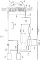
FIGURE 3 is a block diagram of an illustrative example of acooling system 200 for cooling more than one heat-generating structure. As illustrated, thecooling system 200 includes twostructures pump 246. According to one embodiment, thepump 246 provides each of thestructures 212a-b with fluid coolant even when one of the structures 212 is inactive. As a result, the supply of the fluid coolant prevents the inactive structure 212 from dropping below an optimum working temperature. - The
cooling system 200 ofFIGURE 3 is similar to thecooling system 10 ofFIGURE 1 except that thecooling system 200 ofFIGURE 3 includes the twostructures structure inlet lines structure outlet lines FIGURE 3, FIGURE 3 is depicted as being less detailed thanFIGURE 1 . However, in certain embodiments, thecooling system 200 ofFIGURE 3 may contain each of the elements of coolingsystem 10, fewer elements than coolingsystem 10, or more elements than coolingsystem 10. - The structures 212 may be substantially similar to the
structures FIGURE 2 . For example, as discussed inFIGURE 2 , thestructure 212a may be active, while thestructure 212b may be inactive or on standby. In one embodiment, because thestructure 212b is in standby, thestructure 212b is not exposed to, or generating thermal energy. As a result, the temperature of the environment surrounding thecooling system 200 may cause the temperature of thestructure 212b to decrease below an optimal working temperature. According to the present invention, a cooling system may prevent this decrease in temperature. - The
structure outlet lines exchanger inlet line 261. Thepump 246 is similar to thepump 46 ofFIGURE 1 . According to the illustrated, thepump 246 may be a two-section positive displacement pump. For example, a line providing fluid coolant to thepump 246 may be divided into two pump inlet lines. As a result, thepump 246 may not need to separate the fluid coolant because the separation may occur prior to the fluid coolant entering thepump 246. In one embodiment, thepump 246 evenly distributes the fluid coolant between the structure inlet lines 271. In another embodiment, thepump 246 may include two separate pumps. In such an embodiment, thepumps 246 may each receive fluid coolant from separate pump inlet lines, and each of thepumps 246 may provide one of the structure inlet lines 271 with the fluid coolant. According to another embodiment, each of thepumps 246 may be in communication with each other, thus allowing each of thepumps 246 to provide an equal amount of the fluid coolant to each of the structure inlet lines 271. In a further embodiment, thepump 246 may be further operable to separate the fluid coolant and provide it to thestructure inlet lines pump 246 may have only one pump inlet line. - The structure inlet lines 271 may be operable to provide the fluid coolant to the structures 212. As illustrated, the
structure inlet line 271a provides the fluid coolant to thestructure 212a, and thestructure inlet line 271b provides the fluid coolant to thestructure 212b. In one embodiment, each of the structure inlet lines 271 receives an equal amount of the fluid coolant, and further provides an equal amount of the fluid coolant to each of the structures 212. In other embodiments, each of the structure inlet lines 271 may receive a different amount of the fluid coolant, and may or may not provide an equal amount of the fluid coolant to each of the structures 212. In a further embodiment, the fluid coolant provided to the structures 212 by each of the structure inlet lines 271 may have a substantially equal fluid coolant temperature. - The
cooling system 200 further includesstructure group 218a andcooling system 219a. Thestructure group 218a is similar to the structure group 118a ofFIGURE 2 . Thecooling system 219a is similar to thecooling system 119a ofFIGURE 2 . Thestructure group 218a includes both of thestructures cooling system 119a. In operation, the cooling of thestructures cooling system 119a is substantially similar to the cooling of thestructure 12 described inFIGURE 1 . For example, the fluid coolant flows through each of the structure heat exchangers 223, 224 (not shown), absorbing heat from each of the structures 212. The fluid coolant departs the exit conduits 227 (not shown) and flows into the respective structure outlet line 228. The structure outlet lines 228 combine the fluid coolant into the heatexchanger inlet line 261. From the heatexchanger inlet line 261, the fluid coolant flows into theheat exchanger 241. - At the
heat exchanger 241, aflow 256 may be forced to flow through theheat exchanger 241 in order to absorb heat from the fluid coolant. In one embodiment, theflow 256 may be forced byfans flow 256 is similar to theflow 56 ofFIGURE 1 . - After the
heat exchanger 241 transfers heat from the fluid coolant, the fluid coolant departs theheat exchanger 241 and flows through thereservoir 242 and theloop pump 246. Theloop pump 246 separates the fluid coolant and provides the fluid coolant to each of the structure inlet lines 271. In one embodiment, thepump 246 provides an equal amount of the fluid coolant to each of the structure inlet lines 271. From the structure inlet lines 271, the fluid coolant flows through a respective one of two orifices 247 and 248 (not shown) for each of the structures 212, in order to again reach the structure heat exchangers 223, 224 (not shown) for each of the structures 212. - In one embodiment, the environmental temperature may cause the
inactive structure 212b to decrease temperature. However, theinactive structure 212b is constantly receiving a portion of the same fluid coolant that keeps theactive structure 212a at a working temperature. As a result, when the temperature of theinactive structure 212b decreases below the temperature of the fluid coolant entering theinactive structure 212b, the fluid coolant transfers heat to theinactive structure 212b, as apposed to absorbing heat, such as occurs in theactive structure 212a. Because heat is transferred to thestructure 212b, thestructure 212b may remain at an optimum working temperature despite its inactive status and the environmental temperature. In one embodiment, the temperature of thestructure 212b may decrease below the temperature of the fluid coolant entering thestructure 212b because the environmental temperature is lower than that of the fluid coolant. - In a further embodiment, the
system 200 also includes a structure group 218b (not shown). The structure group 218b may include structures 212c and 212d (not shown), and an additional cooling loop 219b (not shown), as discussed inFIGURE 2 . The operations of the structure group 218b is similar to the operation of thestructure group 218a discussed above. In one embodiment, the structures 212c and 212d are similar to thestructures FIGURE 2 , and the cooling loop 219b is similar to thecooling loop 119b ofFIGURE 2 . With both of the structure groups 218, thesystem 200 may include fourstructures 212a-d, and two coolingloops 219a-b. - In another embodiment, the
system 200 may includerelief valves system 200. For example, the relief valves 281 may be operable to remove at least a portion of the fluid coolant from the structure inlet lines 271, and provide the removed fluid coolant back to thereservoir 242. As a result, the relief valves 281 may prevent damage to thesystem 200 when the pressure of thesystem 200 becomes too great. In one embodiment, the relief valves 281 may be controlled by a pressure controller, such as thepressure controller 51 ofFIGURE 1 . In a further embodiment, thesystem 200 may include afilter 243. Thefilter 243 may be operable to maintain the integrity of the fluid coolant entering thepump 246. -
FIGURE 4 is a block diagram of an illustrative example of acooling system 300 for cooling more than one heat-generating structure. Thecooling system 300 ofFIGURE 4 is similar to thecooling system 200 ofFIGURE 3 except that thecooling system 300 ofFIGURE 4 includes asensor 362 and abypass line 363. The other components ofcooling system 300 are similar to those referred to incooling system 200 ofFIGURE 3 . - The
sensor 362 may be operable to measure the temperature of the fluid coolant passing through the heatexchanger inlet line 361. Based on this measurement, thesensor 362 may, in one embodiment, determine that the temperature of the fluid coolant does not need to be decreased. Accordingly,bypass line 363 may direct the fluid coolant to thereservoir 342 without passing through theheat exchanger 341. As a result, the temperature of the fluid coolant may remain substantially constant between structures 312 andreservoir 342. -
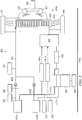
FIGURE 5 is a block diagram of an embodiment of acooling system 400 for cooling more than one heat-generating structure according to the invention. Thecooling system 400 ofFIGURE 5 is similar to thecooling system 200 ofFIGURE 3 except that thecooling system 400 ofFIGURE 5 includes sensors 482-490. The other components ofcooling system 400 are similar to those referred to incooling system 200 ofFIGURE 3 . - In one embodiment, the sensors 482-490 may be operable to provide a diagnosis and/or prognosis of the health of the
system 400. For example, the sensors 482-490 may be operable to measure the pump power of thepump 446, the fan power of thefans system 400, and/or the pressure of thesystem 400. In one embodiment, thesensors sensors sensor 486 may be operable to measure the pressure of the fluid coolant at the heatexchanger inlet line 461. In a further embodiment, thesensor 487
may be operable to measure the pressure drop at theheat exchanger 441. In a further embodiment, thesensor 488 may be operable to measure the pressure inbetween theheat exchanger 441 and thereservoir 442. In a further embodiment, thesensor 489 may be operable to measure the power (voltage/current) of thefans flow 456 through theheat exchanger 441. In a further embodiment, thesensor 490 may be operable to measure the power (voltage/current) of thepump 446. According to one embodiment, the sensors 482-490 of thesystem 400 may allow the performance of individual components of thesystem 400 to be measured, or the entire performance of thesystem 400 to be measured. Based on these measurements, changes can be made to thesystem 400 to fix problems that have occurred, problems that may occur, or problems that are imminent. - Although the present invention has been described with several embodiments, a myriad of changes, variations, alterations, transformations, and modifications may be suggested to one skilled in the art, and it is intended that the present invention encompass such changes, variations, alterations, transformation, and modifications as they fall within the scope of the appended claims.
Claims (13)
- A system (400) for cooling heat-generating structures comprising:an active heat-generating structure (412a);an inactive heat-generating structure (412b);a cooling loop (419a) including a pump (446) that directs a first flow of a fluid coolant to the active heat-generating structure (412a) and a second flow of the fluid coolant to the inactive heat-generating structure (412b), the fluid coolant receiving thermal energy from the active heat-generating structure (412a), the fluid coolant transferring thermal energy to the inactive heat-generating structure (412b) when a temperature of the fluid coolant is greater than an ambient temperature of an environment surrounding the active and inactive heat-generating structures (412a, 412b) whereby the inactive heat-generating structure (412b) may be prevented from dropping below an optimum working temperature, the active heat-generating structure (412a) operable to switch to an inactive state, and the inactive heat-generating structure (412b) operable to switch to an active state;a first sensor (484) operable to measure a temperature of the first flow of the fluid coolant at an outlet line (428a) of the active heat-generating structure (412a) and a second sensor (485) operable to measure a temperature of the second flow of the fluid coolant at an outlet line (428b) of the inactive heat-generating structure (412b); anda heat exchanger (441) in thermal communication with the active and inactive heat-generating structures (412a, 412b), the heat exchanger (441) operable to receive the fluid coolant at a first temperature and dispense of the fluid coolant out of the heat exchanger (441) at a second temperature;the cooling loop (419a) further directing a third flow of the fluid coolant to the heat exchanger (441), the third flow of the fluid coolant being a combination of the first and second flows of the fluid coolant; andthe heat exchanger (441) having an inlet port operable to receive the fluid coolant at the first temperature, and the heat exchanger (441) further having an outlet port operable to dispense of the fluid coolant out of the heat exchanger (441) at the second temperature.
- The system (400) of Claim 1, further comprising:a second active heat-generating structure;a second inactive heat-generating structure;a second cooling loop including a second pump that directs a first flow of a second fluid coolant to the second active heat-generating structure and a second flow of the second fluid coolant to the second inactive heat-generating structure, the second fluid coolant receiving thermal energy from the second active heat-generating structure, the second fluid coolant transferring thermal energy to the second inactive heat-generating structure when a temperature of the second fluid coolant is greater than an ambient temperature of an environment surrounding the second active and inactive heat-generating structures whereby the second inactive heat-generating structure may be prevented from dropping below an optimum working temperature, the second active heat-generating structure operable to switch to an inactive state, and the second inactive heat-generating structure operable to switch to an active state;a third sensor operable to measure a temperature of the first flow of the second fluid coolant at an outlet line of the second active heat-generating structure and a fourth sensor operable to measure a temperature of the second flow of the second fluid coolant at an outlet line of the second inactive heat-generating structure; anda second heat exchanger in thermal communication with the second active and inactive heat-generating structures, the second heat exchanger operable to receive the second fluid coolant at a third temperature and dispense of the second fluid coolant out of the second heat exchanger at a fourth temperature;the second cooling loop further directing a third flow of the second fluid coolant to the second heat exchanger, the third flow of the second fluid coolant being a combination of the first and second flows of the second fluid coolant; andthe second heat exchanger having an inlet port operable to receive the second fluid coolant at the third temperature, and the second heat exchanger further having an outlet port operable to dispense of the second fluid coolant out of the second heat exchanger at the fourth temperature.
- The system (400) of Claim 1, wherein the heat exchanger is either a liquid-air heat exchanger or a liquid-liquid heat exchanger.
- The system (400) of Claim 1, further comprising a sensor (487, 489, 490) operable to measure one of a pump power, fan power, or pressure drop in the system (400).
- The system (400) of Claim 2, wherein the active heat-generating structure (412a) faces a first direction, the inactive heat-generating structure (412b) faces a second direction, the second active heat-generating structure faces a third direction, and the second inactive heat-generating structure faces a fourth direction, the first direction being opposite of the third direction, the second direction being opposite of the fourth direction.
- The system (400) of Claim 2, wherein the first and second flows of the fluid coolant are substantially equal, and wherein the first and second flows of the second fluid coolant are substantially equal.
- The system (400) of Claim 2, wherein the first and second flows of the fluid coolant have substantially equal temperatures, and wherein the first and second flows of the second fluid coolant have substantially equal temperatures.
- A method for cooling heat-generating structures comprising:directing a first flow of a fluid coolant from a pump (446) to a first heat-generating structure (412a);directing a second flow of the fluid coolant from the pump (446) to a second heat-generating structure (412b), one of the first heat-generating structure (412a) or the second heat- generating structure (412b) being in an active state, and another of the first heat-generating structure (412a) or the second heat-generating structure (412b) being in an inactive state;directing a third flow of the fluid coolant to a heat exchanger (441), the third flow of the fluid coolant being a combination of the first and second flows of the fluid coolant, the fluid coolant transferring thermal energy to the first heat-generating structure (412a) or the second heat-generating structure (412b) being in the inactive state when a temperature of the fluid coolant is greater than an ambient temperature of an environment surrounding the first and second heat-generating structures (412a, 412b) whereby the first heat-generating structure (412a) or the second heat-generating structure (412b) being in the inactive state may be prevented from dropping below an optimum working temperature;measuring a temperature of the first flow of the fluid coolant at an outlet line (428a) of the first heat-generating structure (412a) using a first sensor (484) and measuring a temperature of the second flow of the fluid coolant at an outlet line (428b) of the second heat-generating structure (412b) using a second sensor (485);receiving, at the heat exchanger (441), the fluid coolant at a first temperature, the heat exchanger (441) in thermal communication with the first and second heat-generating structures (412a, 412b); anddispensing, from the first heat exchanger (441), the fluid coolant at a second temperature.
- The method of Claim 8, further comprising:directing a first flow of a second fluid coolant from a second pump to a third heat-generating structure;directing a second flow of the second fluid coolant from the second pump to a fourth heat-generating structure, one of the third heat-generating structure or the fourth heat-generating structure being in an active state, and another of the third heat-generating structure or the fourth heat-generating structure being in an inactive state;directing a third flow of the second fluid coolant to a second heat exchanger, the third flow of the second fluid coolant being a combination of the first and second flows of the second fluid coolant, the second fluid coolant transferring thermal energy to the third heat-generating structure or the fourth heat-generating structure being in the inactive state when a temperature of the second fluid coolant is greater than an ambient temperature of an environment surrounding the third and fourth heat-generating structures whereby the third heat-generating structure or the fourth heat-generating structure being in the inactive state may be prevented from dropping below an optimum working temperature;measuring a temperature of the first flow of the second fluid coolant at an outlet line of the third heat-generating structure using a third sensor and measuring a temperature of the second flow of the second fluid coolant at an outlet line of the fourth heat-generating structure using a fourth sensor;receiving, at the second heat exchanger, the second fluid coolant at a third temperature, the second heat exchanger in thermal communication with the third and fourth heat-generating structures; anddispensing, from the second heat exchanger, the second fluid coolant at a fourth temperature.
- The method of Claim 9, wherein the first heat-generating structure (412a) faces a first direction, the second heat-generating structure (412b) faces a second direction, the third heat-generating structure faces a third direction, and the fourth heat-generating structure faces a fourth direction, the first direction being opposite of the third direction, the second direction being opposite of the fourth direction.
- The method of Claim 9, wherein the first and second flows of the fluid coolant are substantially equal, and wherein the first and second flows of the second fluid coolant are substantially equal.
- The method of Claim 9, wherein the first and second flows of the fluid coolant have substantially equal temperatures, and wherein the first and second flows of the second fluid coolant have substantially equal temperatures.
- The method of Claim 9, further comprising:
measuring one or more pressures of the cooling system (400).
Applications Claiming Priority (2)
| Application Number | Priority Date | Filing Date | Title |
|---|---|---|---|
| US11/924,335 US9644869B2 (en) | 2007-10-25 | 2007-10-25 | System and method for cooling structures having both an active state and an inactive state |
| PCT/US2008/074542 WO2009055142A1 (en) | 2007-10-25 | 2008-08-28 | System and method for cooling structures having both an active state and an inactive state |
Publications (2)
| Publication Number | Publication Date |
|---|---|
| EP2201311A1 EP2201311A1 (en) | 2010-06-30 |
| EP2201311B1 true EP2201311B1 (en) | 2019-02-27 |
Family
ID=40032886
Family Applications (1)
| Application Number | Title | Priority Date | Filing Date |
|---|---|---|---|
| EP08798833.3A Active EP2201311B1 (en) | 2007-10-25 | 2008-08-28 | System and method for cooling structures having both an active state and an inactive state |
Country Status (3)
| Country | Link |
|---|---|
| US (1) | US9644869B2 (en) |
| EP (1) | EP2201311B1 (en) |
| WO (1) | WO2009055142A1 (en) |
Families Citing this family (5)
| Publication number | Priority date | Publication date | Assignee | Title |
|---|---|---|---|---|
| EP2246653B1 (en) * | 2009-04-28 | 2012-04-18 | ABB Research Ltd. | Twisted tube thermosyphon |
| EP2246654B1 (en) * | 2009-04-29 | 2013-12-11 | ABB Research Ltd. | Multi-row thermosyphon heat exchanger |
| CN108281401A (en) * | 2017-01-05 | 2018-07-13 | 研能科技股份有限公司 | Three-dimensional chip integrated circuit cooling system |
| US10273867B2 (en) * | 2017-02-02 | 2019-04-30 | GM Global Technology Operations LLC | Prognostic system and method for an electric coolant pump |
| CN113865137B (en) * | 2021-09-08 | 2022-12-09 | 美的集团武汉暖通设备有限公司 | Air source heat pump system and control method of air source heat pump |
Citations (1)
| Publication number | Priority date | Publication date | Assignee | Title |
|---|---|---|---|---|
| US20020101716A1 (en) * | 2000-12-19 | 2002-08-01 | Tsuyoshi Nakagawa | Liquid cooling system for notebook computer |
Family Cites Families (30)
| Publication number | Priority date | Publication date | Assignee | Title |
|---|---|---|---|---|
| US1004212A (en) * | 1911-06-29 | 1911-09-26 | Samuel Charles Smith | Rotary pump. |
| US2466440A (en) * | 1948-07-29 | 1949-04-05 | Kiekhaefer Elmer Carl | Impeller for rotary pumps |
| US2821271A (en) * | 1954-05-03 | 1958-01-28 | Roy S Sanford | Liquid cooled brake with copper friction surfaces |
| US3014429A (en) * | 1959-01-15 | 1961-12-26 | Jabsco Pump Co | Tandem pump |
| US3394655A (en) * | 1966-09-19 | 1968-07-30 | Richard J. Brown | Combined centrifugal and jet type fluid pump |
| DE91228T1 (en) * | 1982-04-07 | 1984-08-16 | Hammond Engineering Ltd., Enfield Middlesex | FAN HOUSING, FAN AND DEVICE PROVIDED WITH THIS FAN. |
| JPS6293426A (en) * | 1985-10-21 | 1987-04-28 | Honda Motor Co Ltd | Cooling water pump for v-type multicylinder engine |
| FR2602035B1 (en) | 1986-04-23 | 1990-05-25 | Michel Bosteels | METHOD AND APPARATUS FOR TRANSFERRING HEAT BETWEEN A FLUID AND A COOLING OR HEATING MEMBER BY DEPRESSION OF THE FLUID WITH RESPECT TO ATMOSPHERIC PRESSURE |
| US4766928A (en) * | 1986-10-27 | 1988-08-30 | Packaged Systems, Inc. | Constant flow rate control valve |
| US5174330A (en) * | 1991-12-05 | 1992-12-29 | Flow Design, Inc. | Constant flow rate control valve with low pressure drop start |
| US5398519A (en) * | 1992-07-13 | 1995-03-21 | Texas Instruments Incorporated | Thermal control system |
| US5459474A (en) * | 1994-03-22 | 1995-10-17 | Martin Marietta Corporation | Active array antenna radar structure |
| WO1996031694A1 (en) * | 1995-04-05 | 1996-10-10 | Schatz Thermo System Gmbh | Method and switching arrangement for operating heat accumulators, in particular for sensible heat |
| DE19606584C2 (en) * | 1995-04-19 | 1997-07-31 | Porsche Ag | Process for cylinder deactivation of an internal combustion engine |
| US5832991A (en) * | 1995-12-29 | 1998-11-10 | Cesaroni; Joseph Anthony | Tube and shell heat exchanger with baffle |
| US5852563A (en) * | 1996-04-10 | 1998-12-22 | Raytheon Ti Systems, Inc. | Intelligent coolant flow control system |
| US6205803B1 (en) * | 1996-04-26 | 2001-03-27 | Mainstream Engineering Corporation | Compact avionics-pod-cooling unit thermal control method and apparatus |
| GB2387275B (en) | 1998-10-09 | 2003-11-26 | Ericsson Inc | Electronics cabinet |
| US6094925A (en) * | 1999-01-29 | 2000-08-01 | Delaware Capital Formation, Inc. | Crossover warm liquid defrost refrigeration system |
| DE10038161A1 (en) | 2000-08-04 | 2002-02-21 | Infineon Technologies Ag | Cooling device for electronic components and method for producing the cooling device |
| US7017651B1 (en) * | 2000-09-13 | 2006-03-28 | Raytheon Company | Method and apparatus for temperature gradient control in an electronic system |
| IT1319610B1 (en) | 2000-12-22 | 2003-10-20 | Siemens Inf & Comm Networks | PROCEDURE AND EQUIPMENT FOR THERMAL CONDITIONING WINDOWS CONTAINING ELECTRONIC EQUIPMENT |
| US6345512B1 (en) * | 2001-06-15 | 2002-02-12 | Marconi Communications, Inc. | Power efficient, compact DC cooling system |
| US6981385B2 (en) * | 2001-08-22 | 2006-01-03 | Delaware Capital Formation, Inc. | Refrigeration system |
| US6684653B2 (en) * | 2001-11-21 | 2004-02-03 | Nicholas H. Des Champs | Air-conditioner and air-to-air heat exchange for closed loop cooling |
| US7000691B1 (en) * | 2002-07-11 | 2006-02-21 | Raytheon Company | Method and apparatus for cooling with coolant at a subambient pressure |
| US6957550B2 (en) * | 2003-05-19 | 2005-10-25 | Raytheon Company | Method and apparatus for extracting non-condensable gases in a cooling system |
| US6952345B2 (en) * | 2003-10-31 | 2005-10-04 | Raytheon Company | Method and apparatus for cooling heat-generating structure |
| US7254957B2 (en) * | 2005-02-15 | 2007-08-14 | Raytheon Company | Method and apparatus for cooling with coolant at a subambient pressure |
| US20070119199A1 (en) | 2005-11-30 | 2007-05-31 | Raytheon Company | System and method for electronic chassis and rack mounted electronics with an integrated subambient cooling system |
-
2007
- 2007-10-25 US US11/924,335 patent/US9644869B2/en active Active
-
2008
- 2008-08-28 WO PCT/US2008/074542 patent/WO2009055142A1/en active Application Filing
- 2008-08-28 EP EP08798833.3A patent/EP2201311B1/en active Active
Patent Citations (1)
| Publication number | Priority date | Publication date | Assignee | Title |
|---|---|---|---|---|
| US20020101716A1 (en) * | 2000-12-19 | 2002-08-01 | Tsuyoshi Nakagawa | Liquid cooling system for notebook computer |
Also Published As
| Publication number | Publication date |
|---|---|
| US20090107663A1 (en) | 2009-04-30 |
| EP2201311A1 (en) | 2010-06-30 |
| WO2009055142A1 (en) | 2009-04-30 |
| US9644869B2 (en) | 2017-05-09 |
Similar Documents
| Publication | Publication Date | Title |
|---|---|---|
| US7254957B2 (en) | Method and apparatus for cooling with coolant at a subambient pressure | |
| US7000691B1 (en) | Method and apparatus for cooling with coolant at a subambient pressure | |
| CA2624308C (en) | Sub-cooling unit for cooling system and method | |
| US8651172B2 (en) | System and method for separating components of a fluid coolant for cooling a structure | |
| US7921655B2 (en) | Topping cycle for a sub-ambient cooling system | |
| US7864527B1 (en) | Systems and methods for close coupled cooling | |
| EP2201311B1 (en) | System and method for cooling structures having both an active state and an inactive state | |
| EP1997362A1 (en) | System and method for cooling a server-based data center | |
| JP2009533764A (en) | Cooling system | |
| EP1601043A2 (en) | Method and apparatus for controlling cooling with coolant at a subambient pressure | |
| JP2005228216A (en) | Electronic device | |
| US20180279511A1 (en) | Cooling system, cooled computer system and computer facility | |
| US20090101311A1 (en) | System and Method for Cooling Using Two Separate Coolants | |
| KR101564172B1 (en) | A hybrid chiller | |
| US11937405B2 (en) | Systems and methods for cooling a fluid circuit for cooling a rack of servers | |
| JP2000323910A (en) | Cooling structure for antenna device | |
| JP2001183026A (en) | Cooling device for moving body | |
| US20130091871A1 (en) | Contaminant cold trap for a vapor-compression refrigeration apparatus | |
| US11991866B2 (en) | Adaptive cascade cooling method for datacenters | |
| JP2013247166A (en) | Airborne cooling device |
Legal Events
| Date | Code | Title | Description |
|---|---|---|---|
| PUAI | Public reference made under article 153(3) epc to a published international application that has entered the european phase |
Free format text: ORIGINAL CODE: 0009012 |
|
| 17P | Request for examination filed |
Effective date: 20100421 |
|
| AK | Designated contracting states |
Kind code of ref document: A1 Designated state(s): AT BE BG CH CY CZ DE DK EE ES FI FR GB GR HR HU IE IS IT LI LT LU LV MC MT NL NO PL PT RO SE SI SK TR |
|
| AX | Request for extension of the european patent |
Extension state: AL BA MK RS |
|
| DAX | Request for extension of the european patent (deleted) | ||
| 17Q | First examination report despatched |
Effective date: 20160212 |
|
| STAA | Information on the status of an ep patent application or granted ep patent |
Free format text: STATUS: EXAMINATION IS IN PROGRESS |
|
| GRAP | Despatch of communication of intention to grant a patent |
Free format text: ORIGINAL CODE: EPIDOSNIGR1 |
|
| STAA | Information on the status of an ep patent application or granted ep patent |
Free format text: STATUS: GRANT OF PATENT IS INTENDED |
|
| RIC1 | Information provided on ipc code assigned before grant |
Ipc: F25B 23/00 20060101AFI20180907BHEP Ipc: F28D 15/00 20060101ALI20180907BHEP Ipc: H01Q 1/02 20060101ALI20180907BHEP Ipc: H01L 23/34 20060101ALI20180907BHEP Ipc: H05K 7/20 20060101ALI20180907BHEP |
|
| INTG | Intention to grant announced |
Effective date: 20180925 |
|
| GRAJ | Information related to disapproval of communication of intention to grant by the applicant or resumption of examination proceedings by the epo deleted |
Free format text: ORIGINAL CODE: EPIDOSDIGR1 |
|
| STAA | Information on the status of an ep patent application or granted ep patent |
Free format text: STATUS: EXAMINATION IS IN PROGRESS |
|
| GRAP | Despatch of communication of intention to grant a patent |
Free format text: ORIGINAL CODE: EPIDOSNIGR1 |
|
| STAA | Information on the status of an ep patent application or granted ep patent |
Free format text: STATUS: GRANT OF PATENT IS INTENDED |
|
| INTC | Intention to grant announced (deleted) | ||
| INTG | Intention to grant announced |
Effective date: 20181121 |
|
| GRAJ | Information related to disapproval of communication of intention to grant by the applicant or resumption of examination proceedings by the epo deleted |
Free format text: ORIGINAL CODE: EPIDOSDIGR1 |
|
| STAA | Information on the status of an ep patent application or granted ep patent |
Free format text: STATUS: EXAMINATION IS IN PROGRESS |
|
| GRAR | Information related to intention to grant a patent recorded |
Free format text: ORIGINAL CODE: EPIDOSNIGR71 |
|
| GRAS | Grant fee paid |
Free format text: ORIGINAL CODE: EPIDOSNIGR3 |
|
| STAA | Information on the status of an ep patent application or granted ep patent |
Free format text: STATUS: GRANT OF PATENT IS INTENDED |
|
| GRAA | (expected) grant |
Free format text: ORIGINAL CODE: 0009210 |
|
| STAA | Information on the status of an ep patent application or granted ep patent |
Free format text: STATUS: THE PATENT HAS BEEN GRANTED |
|
| INTC | Intention to grant announced (deleted) | ||
| INTG | Intention to grant announced |
Effective date: 20190117 |
|
| AK | Designated contracting states |
Kind code of ref document: B1 Designated state(s): AT BE BG CH CY CZ DE DK EE ES FI FR GB GR HR HU IE IS IT LI LT LU LV MC MT NL NO PL PT RO SE SI SK TR |
|
| REG | Reference to a national code |
Ref country code: GB Ref legal event code: FG4D |
|
| REG | Reference to a national code |
Ref country code: CH Ref legal event code: EP |
|
| REG | Reference to a national code |
Ref country code: AT Ref legal event code: REF Ref document number: 1101946 Country of ref document: AT Kind code of ref document: T Effective date: 20190315 |
|
| REG | Reference to a national code |
Ref country code: IE Ref legal event code: FG4D |
|
| REG | Reference to a national code |
Ref country code: DE Ref legal event code: R096 Ref document number: 602008059150 Country of ref document: DE |
|
| REG | Reference to a national code |
Ref country code: NL Ref legal event code: MP Effective date: 20190227 |
|
| REG | Reference to a national code |
Ref country code: LT Ref legal event code: MG4D |
|
| PG25 | Lapsed in a contracting state [announced via postgrant information from national office to epo] |
Ref country code: FI Free format text: LAPSE BECAUSE OF FAILURE TO SUBMIT A TRANSLATION OF THE DESCRIPTION OR TO PAY THE FEE WITHIN THE PRESCRIBED TIME-LIMIT Effective date: 20190227 Ref country code: NO Free format text: LAPSE BECAUSE OF FAILURE TO SUBMIT A TRANSLATION OF THE DESCRIPTION OR TO PAY THE FEE WITHIN THE PRESCRIBED TIME-LIMIT Effective date: 20190527 Ref country code: SE Free format text: LAPSE BECAUSE OF FAILURE TO SUBMIT A TRANSLATION OF THE DESCRIPTION OR TO PAY THE FEE WITHIN THE PRESCRIBED TIME-LIMIT Effective date: 20190227 Ref country code: PT Free format text: LAPSE BECAUSE OF FAILURE TO SUBMIT A TRANSLATION OF THE DESCRIPTION OR TO PAY THE FEE WITHIN THE PRESCRIBED TIME-LIMIT Effective date: 20190627 Ref country code: NL Free format text: LAPSE BECAUSE OF FAILURE TO SUBMIT A TRANSLATION OF THE DESCRIPTION OR TO PAY THE FEE WITHIN THE PRESCRIBED TIME-LIMIT Effective date: 20190227 Ref country code: LT Free format text: LAPSE BECAUSE OF FAILURE TO SUBMIT A TRANSLATION OF THE DESCRIPTION OR TO PAY THE FEE WITHIN THE PRESCRIBED TIME-LIMIT Effective date: 20190227 |
|
| PG25 | Lapsed in a contracting state [announced via postgrant information from national office to epo] |
Ref country code: LV Free format text: LAPSE BECAUSE OF FAILURE TO SUBMIT A TRANSLATION OF THE DESCRIPTION OR TO PAY THE FEE WITHIN THE PRESCRIBED TIME-LIMIT Effective date: 20190227 Ref country code: GR Free format text: LAPSE BECAUSE OF FAILURE TO SUBMIT A TRANSLATION OF THE DESCRIPTION OR TO PAY THE FEE WITHIN THE PRESCRIBED TIME-LIMIT Effective date: 20190528 Ref country code: BG Free format text: LAPSE BECAUSE OF FAILURE TO SUBMIT A TRANSLATION OF THE DESCRIPTION OR TO PAY THE FEE WITHIN THE PRESCRIBED TIME-LIMIT Effective date: 20190527 Ref country code: HR Free format text: LAPSE BECAUSE OF FAILURE TO SUBMIT A TRANSLATION OF THE DESCRIPTION OR TO PAY THE FEE WITHIN THE PRESCRIBED TIME-LIMIT Effective date: 20190227 Ref country code: IS Free format text: LAPSE BECAUSE OF FAILURE TO SUBMIT A TRANSLATION OF THE DESCRIPTION OR TO PAY THE FEE WITHIN THE PRESCRIBED TIME-LIMIT Effective date: 20190627 |
|
| REG | Reference to a national code |
Ref country code: AT Ref legal event code: MK05 Ref document number: 1101946 Country of ref document: AT Kind code of ref document: T Effective date: 20190227 |
|
| PG25 | Lapsed in a contracting state [announced via postgrant information from national office to epo] |
Ref country code: DK Free format text: LAPSE BECAUSE OF FAILURE TO SUBMIT A TRANSLATION OF THE DESCRIPTION OR TO PAY THE FEE WITHIN THE PRESCRIBED TIME-LIMIT Effective date: 20190227 Ref country code: ES Free format text: LAPSE BECAUSE OF FAILURE TO SUBMIT A TRANSLATION OF THE DESCRIPTION OR TO PAY THE FEE WITHIN THE PRESCRIBED TIME-LIMIT Effective date: 20190227 Ref country code: EE Free format text: LAPSE BECAUSE OF FAILURE TO SUBMIT A TRANSLATION OF THE DESCRIPTION OR TO PAY THE FEE WITHIN THE PRESCRIBED TIME-LIMIT Effective date: 20190227 Ref country code: RO Free format text: LAPSE BECAUSE OF FAILURE TO SUBMIT A TRANSLATION OF THE DESCRIPTION OR TO PAY THE FEE WITHIN THE PRESCRIBED TIME-LIMIT Effective date: 20190227 Ref country code: SK Free format text: LAPSE BECAUSE OF FAILURE TO SUBMIT A TRANSLATION OF THE DESCRIPTION OR TO PAY THE FEE WITHIN THE PRESCRIBED TIME-LIMIT Effective date: 20190227 Ref country code: CZ Free format text: LAPSE BECAUSE OF FAILURE TO SUBMIT A TRANSLATION OF THE DESCRIPTION OR TO PAY THE FEE WITHIN THE PRESCRIBED TIME-LIMIT Effective date: 20190227 |
|
| REG | Reference to a national code |
Ref country code: DE Ref legal event code: R097 Ref document number: 602008059150 Country of ref document: DE |
|
| PG25 | Lapsed in a contracting state [announced via postgrant information from national office to epo] |
Ref country code: PL Free format text: LAPSE BECAUSE OF FAILURE TO SUBMIT A TRANSLATION OF THE DESCRIPTION OR TO PAY THE FEE WITHIN THE PRESCRIBED TIME-LIMIT Effective date: 20190227 |
|
| PG25 | Lapsed in a contracting state [announced via postgrant information from national office to epo] |
Ref country code: AT Free format text: LAPSE BECAUSE OF FAILURE TO SUBMIT A TRANSLATION OF THE DESCRIPTION OR TO PAY THE FEE WITHIN THE PRESCRIBED TIME-LIMIT Effective date: 20190227 |
|
| PLBE | No opposition filed within time limit |
Free format text: ORIGINAL CODE: 0009261 |
|
| STAA | Information on the status of an ep patent application or granted ep patent |
Free format text: STATUS: NO OPPOSITION FILED WITHIN TIME LIMIT |
|
| 26N | No opposition filed |
Effective date: 20191128 |
|
| PG25 | Lapsed in a contracting state [announced via postgrant information from national office to epo] |
Ref country code: SI Free format text: LAPSE BECAUSE OF FAILURE TO SUBMIT A TRANSLATION OF THE DESCRIPTION OR TO PAY THE FEE WITHIN THE PRESCRIBED TIME-LIMIT Effective date: 20190227 |
|
| PG25 | Lapsed in a contracting state [announced via postgrant information from national office to epo] |
Ref country code: TR Free format text: LAPSE BECAUSE OF FAILURE TO SUBMIT A TRANSLATION OF THE DESCRIPTION OR TO PAY THE FEE WITHIN THE PRESCRIBED TIME-LIMIT Effective date: 20190227 |
|
| PG25 | Lapsed in a contracting state [announced via postgrant information from national office to epo] |
Ref country code: CH Free format text: LAPSE BECAUSE OF NON-PAYMENT OF DUE FEES Effective date: 20190831 Ref country code: MC Free format text: LAPSE BECAUSE OF FAILURE TO SUBMIT A TRANSLATION OF THE DESCRIPTION OR TO PAY THE FEE WITHIN THE PRESCRIBED TIME-LIMIT Effective date: 20190227 Ref country code: LI Free format text: LAPSE BECAUSE OF NON-PAYMENT OF DUE FEES Effective date: 20190831 Ref country code: LU Free format text: LAPSE BECAUSE OF NON-PAYMENT OF DUE FEES Effective date: 20190828 |
|
| REG | Reference to a national code |
Ref country code: BE Ref legal event code: MM Effective date: 20190831 |
|
| PG25 | Lapsed in a contracting state [announced via postgrant information from national office to epo] |
Ref country code: IE Free format text: LAPSE BECAUSE OF NON-PAYMENT OF DUE FEES Effective date: 20190828 |
|
| PG25 | Lapsed in a contracting state [announced via postgrant information from national office to epo] |
Ref country code: BE Free format text: LAPSE BECAUSE OF NON-PAYMENT OF DUE FEES Effective date: 20190831 |
|
| PG25 | Lapsed in a contracting state [announced via postgrant information from national office to epo] |
Ref country code: CY Free format text: LAPSE BECAUSE OF FAILURE TO SUBMIT A TRANSLATION OF THE DESCRIPTION OR TO PAY THE FEE WITHIN THE PRESCRIBED TIME-LIMIT Effective date: 20190227 |
|
| PG25 | Lapsed in a contracting state [announced via postgrant information from national office to epo] |
Ref country code: HU Free format text: LAPSE BECAUSE OF FAILURE TO SUBMIT A TRANSLATION OF THE DESCRIPTION OR TO PAY THE FEE WITHIN THE PRESCRIBED TIME-LIMIT; INVALID AB INITIO Effective date: 20080828 Ref country code: MT Free format text: LAPSE BECAUSE OF FAILURE TO SUBMIT A TRANSLATION OF THE DESCRIPTION OR TO PAY THE FEE WITHIN THE PRESCRIBED TIME-LIMIT Effective date: 20190227 |
|
| P01 | Opt-out of the competence of the unified patent court (upc) registered |
Effective date: 20230530 |
|
| PGFP | Annual fee paid to national office [announced via postgrant information from national office to epo] |
Ref country code: IT Payment date: 20230720 Year of fee payment: 16 Ref country code: GB Payment date: 20230720 Year of fee payment: 16 |
|
| PGFP | Annual fee paid to national office [announced via postgrant information from national office to epo] |
Ref country code: FR Payment date: 20230720 Year of fee payment: 16 Ref country code: DE Payment date: 20230720 Year of fee payment: 16 |