EP2199827B1 - Clutter signal filtering for Doppler signal - Google Patents
Clutter signal filtering for Doppler signal Download PDFInfo
- Publication number
- EP2199827B1 EP2199827B1 EP09179074.1A EP09179074A EP2199827B1 EP 2199827 B1 EP2199827 B1 EP 2199827B1 EP 09179074 A EP09179074 A EP 09179074A EP 2199827 B1 EP2199827 B1 EP 2199827B1
- Authority
- EP
- European Patent Office
- Prior art keywords
- signal
- doppler
- doppler signal
- ifr
- clutter
- Prior art date
- Legal status (The legal status is an assumption and is not a legal conclusion. Google has not performed a legal analysis and makes no representation as to the accuracy of the status listed.)
- Active
Links
- 238000001914 filtration Methods 0.000 title claims description 23
- 238000002604 ultrasonography Methods 0.000 claims description 29
- 238000000034 method Methods 0.000 claims description 19
- 230000017531 blood circulation Effects 0.000 description 9
- 238000010586 diagram Methods 0.000 description 7
- 238000003384 imaging method Methods 0.000 description 5
- 239000000523 sample Substances 0.000 description 5
- 238000001228 spectrum Methods 0.000 description 4
- 238000001514 detection method Methods 0.000 description 3
- 238000005070 sampling Methods 0.000 description 3
- 230000003044 adaptive effect Effects 0.000 description 2
- 230000000747 cardiac effect Effects 0.000 description 2
- 230000001066 destructive effect Effects 0.000 description 1
- 238000003745 diagnosis Methods 0.000 description 1
- 238000012285 ultrasound imaging Methods 0.000 description 1
Images


Classifications
-
- A—HUMAN NECESSITIES
- A61—MEDICAL OR VETERINARY SCIENCE; HYGIENE
- A61B—DIAGNOSIS; SURGERY; IDENTIFICATION
- A61B8/00—Diagnosis using ultrasonic, sonic or infrasonic waves
- A61B8/13—Tomography
- A61B8/14—Echo-tomography
-
- G—PHYSICS
- G01—MEASURING; TESTING
- G01S—RADIO DIRECTION-FINDING; RADIO NAVIGATION; DETERMINING DISTANCE OR VELOCITY BY USE OF RADIO WAVES; LOCATING OR PRESENCE-DETECTING BY USE OF THE REFLECTION OR RERADIATION OF RADIO WAVES; ANALOGOUS ARRANGEMENTS USING OTHER WAVES
- G01S15/00—Systems using the reflection or reradiation of acoustic waves, e.g. sonar systems
- G01S15/88—Sonar systems specially adapted for specific applications
- G01S15/89—Sonar systems specially adapted for specific applications for mapping or imaging
- G01S15/8906—Short-range imaging systems; Acoustic microscope systems using pulse-echo techniques
- G01S15/8979—Combined Doppler and pulse-echo imaging systems
- G01S15/8981—Discriminating between fixed and moving objects or between objects moving at different speeds, e.g. wall clutter filter
Definitions
- the present disclosure relates to ultrasound signal processing, and more particularly to clutter signal filtering for Doppler signal in an ultrasound system.
- an ultrasound system has been extensively used in the medical field due to its non-invasive and non-destructive nature.
- Modern high-performance ultrasound imaging diagnostic systems and techniques are commonly used to produce two- or three-dimensional ultrasound images of internal features of patients.
- the ultrasound system operates in various image modes such as a brightness mode, a Doppler mode and the like to acquire ultrasound images for diagnosis.
- the ultrasound system provides a color flow image showing velocities of moving objects such as blood flow, heart, etc.
- the color flow image may be formed based on a Doppler signal obtained by alternately transmitting and receiving ultrasound signals to and from a target object.
- the Doppler signal may include a low frequency signal (the so-called clutter signal) due to the motion of a cardiac wall or valve of a heart.
- the clutter signal may have amplitude, which is over 100 times than that of a pure Doppler signal indicative of velocities of the blood flow.
- the clutter signal may be an obstacle to accurately detect a velocity of the blood flow. Thus, it is required to remove the clutter signal from the Doppler signal for accurate velocity detection of the blood flow.
- the ultrasound system typically adopts a clutter filter, which may be a high pass filter, to remove the clutter signal from the Doppler signal.
- Two clutter filtering methods have been adopted to remove the clutter signal from the Doppler signal.
- One is a clutter filtering method using a clutter power threshold.
- the other is a clutter filtering method using variance information of the clutter signal.
- the clutter filtering method using the clutter power threshold may be carried out by modulating the Doppler signal when the amplitude of the Doppler signal is greater than the clutter power threshold. Thereafter, the modulated Doppler signal may be filtered by using a clutter filter having a predetermined cutoff frequency. In such a method, however, if the amplitude of the Doppler signal is less than the clutter power threshold, then the modulation may not be performed. Also, when the power level of the pure Doppler signal is close to that of the clutter signal, the modulation may not be desirably performed. Thus, the clutter signal may not be effectively removed from the Doppler signal.
- the clutter filtering method using the variance information of clutter signal may be carried out by changing a cutoff frequency of a clutter filter.
- the clutter filter adopted in the conventional ultrasound system may remove the clutter signal in the Doppler signal by suppressing the frequency components thereof below a specific cutoff frequency. In such a case, however, if the cutoff frequency is set to a high value, then relatively low frequencies of the pure Doppler signal may be also cut off along with the clutter signal. Thus, it may be difficult to accurately detect the velocities of the blood flow.
- EP 0 524 774 A2 discloses an ultrasonic Doppler imaging apparatus in which the velocity of a blood flow in a living body can be computed with high precision without increasing a scale of a signal processing circuit, so that a Doppler color image having satisfactory image quality is displayed.
- an ultrasonic pulse signal is transmitted into the living body and is reflected from a target in the living body to be received by an ultrasonic probe, and the reception signal is subjected to quadrature phase detection to obtain an I signal and a Q signal.
- a power of a phase detection output signal applied to the input of an MTI filter is computed by an input power computing section and a power of the output signal of the MTI filter is computed by an output power computing section.
- XP004463713 "Adaptive clutter filtering for ultrasound color flow imaging" by Yang Mo Yoo et. al. discloses an adaptive clutter rejection method for selecting different clutter filters in ultrasound color flow imaging.
- XP032084664 "An improved wall filter for flow imaging of low velocity flow" by L. Thomas and A. Hall discloses methods for flow estimation for blood flow imaging.
- an ultrasound system includes the features of claim 1.
- a method of filtering clutter signal from Doppler signal comprises the features of claim 5.
- the ultrasound system 100 may include a Doppler signal acquisition unit 110.
- the Doppler signal acquisition unit 110 is operable to alternately transmit and receive ultrasound signals to and from a target object (e.g., heart, blood flow, etc) in synchronization with a pulse repetition frequency (PRF) to thereby acquire a Doppler signal.
- the Doppler signal may include a clutter signal due to the motion of cardiac walls or valves of a heart together with a pure Doppler signal indicating velocities of a blood flow.
- the Doppler signal acquisition unit 110 may include a transmit signal generator (not shown) configured to generate transmit pulse signals.
- the Doppler signal acquisition unit 110 may further include an ultrasound probe (not shown) that may be operable to transmit ultrasound signals to the target object in response to the transmit pulse signals and receive ultrasound echo signals reflected from the target object to thereby output an electrical receive signal.
- the Doppler signal acquisition unit 110 may further include a beam former (not shown), which may be operable to perform receive-focusing upon the electrical receive signal to obtain a receive-focused signal.
- the Doppler signal acquisition unit 110 may further include a Doppler signal forming section (not shown) that may be operable to sample the receive-focused signal at a predetermined sampling frequency and perform signal processing upon the sampled signal to acquire the Doppler signal.
- the ultrasound system 100 may further include a signal processing unit 120.
- the signal processing unit 120 is operable to analyze characteristics of the Doppler signal such as a mean power, mean velocity, variance, etc. thereof to determine whether to modulate the Doppler signal or change a cutoff frequency of a clutter filter necessary for clutter signal removal from the Doppler signal.
- the signal processing unit 120 is further operable to perform auto correlation, arc tangent operation, etc. upon the Doppler signal.
- FIG. 2 is a block diagram showing an illustrative embodiment of the signal processing unit 120.
- the signal processing unit 120 may include a first signal information forming section 121.
- the first signal information forming section 121 is operable to analyze the characteristics of the Doppler signal provided form the Doppler signal acquisition unit 110 to form first signal information.
- the first signal information may include a mean power, a mean velocity, a variance, etc. of the Doppler signal.
- the mean power P, the mean velocity V and the variance ⁇ may be computed by the following equations.
- the signal processing unit 120 may further include a first clutter filter 122 coupled to the Doppler signal acquisition unit 110 to receive the Doppler signal.
- the first clutter filter 122 is operable to perform filtering upon the Doppler signal to remove the clutter signal therefrom.
- the first clutter filter 122 may use a cutoff frequency to be set within about 10% from a half of the predetermined sampling frequency used to sample the receive-focused signal for acquiring the Doppler signal.
- the signal processing unit 120 may further include a second signal information forming section 123 coupled to the first clutter filter 122 to receive the filtered Doppler signal.
- the second signal information forming section 123 is operable to analyze the filtered Doppler signal to form second signal information.
- the second signal information may include a mean power, a mean velocity, variance, etc. of the filtered Doppler signal.
- the mean power, mean velocity and variance may be also computed by the above equations (1).
- the signal processing unit 120 may further include an input signal power to filtered input signal power rate (IFR) computing section 124 coupled to the first and second signal information forming sections 121 and 123 to receive the first and second signal information.
- IFR input signal power to filtered input signal power rate
- the signal processing unit 120 may further include a control section 125 coupled to the IFR computing section 124.
- the control section 125 is operable to compare the IFR with a predetermined threshold.
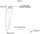
- a predetermined threshold When the Doppler signal having relatively high power exists in a low frequency region lower than PRF/2 on a frequency domain and a mean frequency representative of a mean velocity thereof is relatively low, as shown FIG. 3 , the IFR may be typically greater than 20. Thus, for example, 20 may be set as the predetermined threshold. If the IFR is greater than the predetermined threshold (e.g., 20), then the control section 125 is operable to generate a first control signal.
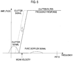
- the mean frequency representative of the mean velocity of the Doppler signal is positioned at the middle of the Doppler signal, as illustrated in FIG. 5 .
- the IFR may be a value ranging from 5 to 20. Since the mean velocity of the Doppler signal is largely different from the mean velocity of the clutter signal, the clutter signal may not be effectively removed through the clutter filtering method using a clutter power threshold. Thus, when the IFR is less than the predetermined threshold, the control section 125 is operable to generate a second control signal.
- the signal processing unit 120 may further include a modulating section 126 that may operate under the control of the control section 125.
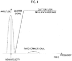
- the modulating section 126 is operable to set a predetermined modulation frequency in response to the first control signal and modulate the Doppler signal based on the predetermined modulation frequency to thereby output a modulated Doppler signal, as illustrated in FIG. 4 .
- the modulating section 126 is further operable to set the modulation frequency to zero in response to the second control signal. That is, if the second control signal is received from the control section 125, then the modulating section 126 may not modulate the Doppler signal.
- the signal processing unit 120 may further include a second clutter filter 127 that may operate under the control of the control section 125.
- the second clutter filter 127 is operable to perform filtering upon the modulated Doppler signal to remove the clutter signal therefrom by using a cutoff frequency, which is identical to that used in the first clutter filter 122, in response to the first control signal. That is, the cutoff frequency may be set to be within about 10% from a half of a sampling frequency used to sample the receive-focused signal for acquiring the Doppler signal. If the second control signal is received from the control section 125, then the second clutter filter 127 may be operable to adjust the cutoff frequency to remove the clutter signal from the Doppler signal, as illustrated in FIG. 6 . In such a case, the cutoff frequency may be changed based on a frequency representative of the mean velocity formed by the first signal information forming section 121.
- the signal processing unit 120 may further include a demodulating section 128.
- the demodulating section 128 is operable to set a demodulation frequency by using a frequency corresponding to the mean velocity formed by the first signal information forming section 121 in response to the first control signal.
- the demodulating section 128 is further operable to demodulate the modulated Doppler signal provided from the second clutter filter 127. If the second control signal is received, then the demodulating section 128 is operable to set the modulation frequency to zero. That is, the demodulating section 128 may not demodulate the Doppler signal outputted from the second clutter filter 127 in response to the second control signal.
- the ultrasound system 100 may further include an image forming unit 130.
- the image forming unit 130 is operable to form a Doppler image based on the Doppler signal outputted from the signal processing unit.
- the Doppler image may be displayed on a display unit 140.
- the display unit 140 may include at least one of CRT display, LCD, plate panel display and the like.
Landscapes
- Physics & Mathematics (AREA)
- Engineering & Computer Science (AREA)
- Radar, Positioning & Navigation (AREA)
- Remote Sensing (AREA)
- Acoustics & Sound (AREA)
- Health & Medical Sciences (AREA)
- Life Sciences & Earth Sciences (AREA)
- Computer Networks & Wireless Communication (AREA)
- General Physics & Mathematics (AREA)
- Radiology & Medical Imaging (AREA)
- Molecular Biology (AREA)
- Pathology (AREA)
- Biophysics (AREA)
- Biomedical Technology (AREA)
- Heart & Thoracic Surgery (AREA)
- Medical Informatics (AREA)
- Nuclear Medicine, Radiotherapy & Molecular Imaging (AREA)
- Surgery (AREA)
- Animal Behavior & Ethology (AREA)
- General Health & Medical Sciences (AREA)
- Public Health (AREA)
- Veterinary Medicine (AREA)
- Ultra Sonic Daignosis Equipment (AREA)
- Measurement Of Velocity Or Position Using Acoustic Or Ultrasonic Waves (AREA)
Description
- The present disclosure relates to ultrasound signal processing, and more particularly to clutter signal filtering for Doppler signal in an ultrasound system.
- Recently, an ultrasound system has been extensively used in the medical field due to its non-invasive and non-destructive nature. Modern high-performance ultrasound imaging diagnostic systems and techniques are commonly used to produce two- or three-dimensional ultrasound images of internal features of patients. In order to provide the ultrasound images, the ultrasound system operates in various image modes such as a brightness mode, a Doppler mode and the like to acquire ultrasound images for diagnosis.
- In the Doppler mode, the ultrasound system provides a color flow image showing velocities of moving objects such as blood flow, heart, etc. The color flow image may be formed based on a Doppler signal obtained by alternately transmitting and receiving ultrasound signals to and from a target object. The Doppler signal may include a low frequency signal (the so-called clutter signal) due to the motion of a cardiac wall or valve of a heart. The clutter signal may have amplitude, which is over 100 times than that of a pure Doppler signal indicative of velocities of the blood flow. The clutter signal may be an obstacle to accurately detect a velocity of the blood flow. Thus, it is required to remove the clutter signal from the Doppler signal for accurate velocity detection of the blood flow. The ultrasound system typically adopts a clutter filter, which may be a high pass filter, to remove the clutter signal from the Doppler signal.
- Recently, two clutter filtering methods have been adopted to remove the clutter signal from the Doppler signal. One is a clutter filtering method using a clutter power threshold. The other is a clutter filtering method using variance information of the clutter signal.
- The clutter filtering method using the clutter power threshold may be carried out by modulating the Doppler signal when the amplitude of the Doppler signal is greater than the clutter power threshold. Thereafter, the modulated Doppler signal may be filtered by using a clutter filter having a predetermined cutoff frequency. In such a method, however, if the amplitude of the Doppler signal is less than the clutter power threshold, then the modulation may not be performed. Also, when the power level of the pure Doppler signal is close to that of the clutter signal, the modulation may not be desirably performed. Thus, the clutter signal may not be effectively removed from the Doppler signal.
- The clutter filtering method using the variance information of clutter signal may be carried out by changing a cutoff frequency of a clutter filter. The clutter filter adopted in the conventional ultrasound system may remove the clutter signal in the Doppler signal by suppressing the frequency components thereof below a specific cutoff frequency. In such a case, however, if the cutoff frequency is set to a high value, then relatively low frequencies of the pure Doppler signal may be also cut off along with the clutter signal. Thus, it may be difficult to accurately detect the velocities of the blood flow.
-
EP 0 524 774 A2 discloses an ultrasonic Doppler imaging apparatus in which the velocity of a blood flow in a living body can be computed with high precision without increasing a scale of a signal processing circuit, so that a Doppler color image having satisfactory image quality is displayed. In the apparatus, an ultrasonic pulse signal is transmitted into the living body and is reflected from a target in the living body to be received by an ultrasonic probe, and the reception signal is subjected to quadrature phase detection to obtain an I signal and a Q signal. According to the method described therein, a power of a phase detection output signal applied to the input of an MTI filter is computed by an input power computing section and a power of the output signal of the MTI filter is computed by an output power computing section. These two powers are then compared with each other and a result of the comparison is supplied to a coefficient control section. - XP004463713 "Adaptive clutter filtering for ultrasound color flow imaging" by Yang Mo Yoo et. al. discloses an adaptive clutter rejection method for selecting different clutter filters in ultrasound color flow imaging.
- XP032084664 "An improved wall filter for flow imaging of low velocity flow" by L. Thomas and A. Hall discloses methods for flow estimation for blood flow imaging.
- Embodiments for setting cutoff frequencies of clutter filters based on power and mean frequency of clutter signal are disclosed herein. In one embodiment an ultrasound system includes the features of
claim 1. - In another embodiment, a method of filtering clutter signal from Doppler signal comprises the features of claim 5.
- The Summary is provided to introduce a selection of concepts in a simplified form that are further described below in the Detailed Description. This Summary is not intended to identify key or essential features of the claimed subject matter, nor is it intended to be used in determining the scope of the claimed subject matter.
-
- FIG. 1
- is a block diagram showing an illustrative embodiment of an ultrasound system.
- FIG. 2
- is a block diagram showing an illustrative embodiment of a signal processing unit.
- FIG. 3
- is a diagram showing an illustrative embodiment of a frequency spectrum of a Doppler signal containing a clutter signal and a frequency response of a clutter filter, wherein a mean frequency of the Doppler signal is lower than a half pulse repetition frequency, and wherein the frequency representative of a mean velocity is relatively low.
- FIG. 4
- is a diagram showing an illustrative embodiment of a frequency spectrum of a modulated Doppler signal containing a modulated clutter signal and a frequency response of a clutter filter.
- FIG. 5
- is a diagram showing an illustrative embodiment of a frequency spectrum of a Doppler signal containing a clutter signal and a frequency response of a clutter filter, wherein a mean power of the clutter signal is close to that of the pure Doppler signal.
- FIG. 6
- is a diagram showing an illustrative embodiment of a frequency spectrum of a Doppler signal containing a clutter signal and adjustment of a frequency response of a clutter filter.
- A detailed description is provided with reference to the accompanying drawings. One of ordinary skill in the art may realize that the following description is illustrative only and is not in any way limiting.
- Referring to
FIG. 1 , an illustrative embodiment of anultrasound system 100 is shown. As depicted therein, theultrasound system 100 may include a Dopplersignal acquisition unit 110. The Dopplersignal acquisition unit 110 is operable to alternately transmit and receive ultrasound signals to and from a target object (e.g., heart, blood flow, etc) in synchronization with a pulse repetition frequency (PRF) to thereby acquire a Doppler signal. The Doppler signal may include a clutter signal due to the motion of cardiac walls or valves of a heart together with a pure Doppler signal indicating velocities of a blood flow. In one embodiment, the Dopplersignal acquisition unit 110 may include a transmit signal generator (not shown) configured to generate transmit pulse signals. The Dopplersignal acquisition unit 110 may further include an ultrasound probe (not shown) that may be operable to transmit ultrasound signals to the target object in response to the transmit pulse signals and receive ultrasound echo signals reflected from the target object to thereby output an electrical receive signal. The Dopplersignal acquisition unit 110 may further include a beam former (not shown), which may be operable to perform receive-focusing upon the electrical receive signal to obtain a receive-focused signal. The Dopplersignal acquisition unit 110 may further include a Doppler signal forming section (not shown) that may be operable to sample the receive-focused signal at a predetermined sampling frequency and perform signal processing upon the sampled signal to acquire the Doppler signal. - The
ultrasound system 100 may further include asignal processing unit 120. Thesignal processing unit 120 is operable to analyze characteristics of the Doppler signal such as a mean power, mean velocity, variance, etc. thereof to determine whether to modulate the Doppler signal or change a cutoff frequency of a clutter filter necessary for clutter signal removal from the Doppler signal. Thesignal processing unit 120 is further operable to perform auto correlation, arc tangent operation, etc. upon the Doppler signal. -
FIG. 2 is a block diagram showing an illustrative embodiment of thesignal processing unit 120. As shown inFIG. 2 , thesignal processing unit 120 may include a first signalinformation forming section 121. The first signalinformation forming section 121 is operable to analyze the characteristics of the Doppler signal provided form the Dopplersignal acquisition unit 110 to form first signal information. In one embodiment, by way of non-limiting example, the first signal information may include a mean power, a mean velocity, a variance, etc. of the Doppler signal. The mean power P, the mean velocity V and the variance σ may be computed by the following equations.
- The
signal processing unit 120 may further include afirst clutter filter 122 coupled to the Dopplersignal acquisition unit 110 to receive the Doppler signal. Thefirst clutter filter 122 is operable to perform filtering upon the Doppler signal to remove the clutter signal therefrom. In one embodiment, thefirst clutter filter 122 may use a cutoff frequency to be set within about 10% from a half of the predetermined sampling frequency used to sample the receive-focused signal for acquiring the Doppler signal. - The
signal processing unit 120 may further include a second signalinformation forming section 123 coupled to thefirst clutter filter 122 to receive the filtered Doppler signal. The second signalinformation forming section 123 is operable to analyze the filtered Doppler signal to form second signal information. The second signal information may include a mean power, a mean velocity, variance, etc. of the filtered Doppler signal. The mean power, mean velocity and variance may be also computed by the above equations (1). - The
signal processing unit 120 may further include an input signal power to filtered input signal power rate (IFR)computing section 124 coupled to the first and second signalinformation forming sections IFR computing section 124 is operable to compute the IFR by using mean powers included in the first and second signal information by using the following equation.
- The
signal processing unit 120 may further include acontrol section 125 coupled to theIFR computing section 124. Thecontrol section 125 is operable to compare the IFR with a predetermined threshold. When the Doppler signal having relatively high power exists in a low frequency region lower than PRF/2 on a frequency domain and a mean frequency representative of a mean velocity thereof is relatively low, as shownFIG. 3 , the IFR may be typically greater than 20. Thus, for example, 20 may be set as the predetermined threshold. If the IFR is greater than the predetermined threshold (e.g., 20), then thecontrol section 125 is operable to generate a first control signal. On the other hand, when the mean power of the clutter signal is close to that of the pure Doppler signal, the mean frequency representative of the mean velocity of the Doppler signal is positioned at the middle of the Doppler signal, as illustrated inFIG. 5 . In such a case, the IFR may be a value ranging from 5 to 20. Since the mean velocity of the Doppler signal is largely different from the mean velocity of the clutter signal, the clutter signal may not be effectively removed through the clutter filtering method using a clutter power threshold. Thus, when the IFR is less than the predetermined threshold, thecontrol section 125 is operable to generate a second control signal. - The
signal processing unit 120 may further include amodulating section 126 that may operate under the control of thecontrol section 125. The modulatingsection 126 is operable to set a predetermined modulation frequency in response to the first control signal and modulate the Doppler signal based on the predetermined modulation frequency to thereby output a modulated Doppler signal, as illustrated inFIG. 4 . The modulatingsection 126 is further operable to set the modulation frequency to zero in response to the second control signal. That is, if the second control signal is received from thecontrol section 125, then themodulating section 126 may not modulate the Doppler signal. - The
signal processing unit 120 may further include asecond clutter filter 127 that may operate under the control of thecontrol section 125. Thesecond clutter filter 127 is operable to perform filtering upon the modulated Doppler signal to remove the clutter signal therefrom by using a cutoff frequency, which is identical to that used in thefirst clutter filter 122, in response to the first control signal. That is, the cutoff frequency may be set to be within about 10% from a half of a sampling frequency used to sample the receive-focused signal for acquiring the Doppler signal. If the second control signal is received from thecontrol section 125, then thesecond clutter filter 127 may be operable to adjust the cutoff frequency to remove the clutter signal from the Doppler signal, as illustrated inFIG. 6 . In such a case, the cutoff frequency may be changed based on a frequency representative of the mean velocity formed by the first signalinformation forming section 121. - The
signal processing unit 120 may further include ademodulating section 128. Thedemodulating section 128 is operable to set a demodulation frequency by using a frequency corresponding to the mean velocity formed by the first signalinformation forming section 121 in response to the first control signal. Thedemodulating section 128 is further operable to demodulate the modulated Doppler signal provided from thesecond clutter filter 127. If the second control signal is received, then thedemodulating section 128 is operable to set the modulation frequency to zero. That is, thedemodulating section 128 may not demodulate the Doppler signal outputted from thesecond clutter filter 127 in response to the second control signal. - Referring back to
FIG. 1 , theultrasound system 100 may further include animage forming unit 130. Theimage forming unit 130 is operable to form a Doppler image based on the Doppler signal outputted from the signal processing unit. The Doppler image may be displayed on adisplay unit 140. Thedisplay unit 140 may include at least one of CRT display, LCD, plate panel display and the like.
Claims (11)
- An ultrasound system (100), comprising:a Doppler signal acquiring unit (110) configured to transmit and receive ultrasound signals to and from a target object to acquire a Doppler signal; anda signal processing unit (120) configured to perform filtering upon the Doppler signal by using a first clutter filter (122) having a first cutoff frequency and compute an input signal power to filtered input signal power rate, IFR, for the Doppler signal, characterised by the signal processing unit (120) being further configured to be responsive to the IFR to perform modulation of the Doppler signal and filtering upon the modulated Doppler signal by using the first clutter filter (122) or to perform filtering the Doppler signal by using a second clutter filter (127)
having a second cutoff frequency which is higher than the first cutoff frequency without modulation of the Doppler signal. - The ultrasound system (100) of Claim 1, wherein the signal processing unit (120) includes:a first signal information acquiring section configured to analyze the Doppler signal to acquire first signal information;
the first clutter filter (122) configured to perform filtering upon the Doppler signal by using the first cutoff frequency to thereby output a first filtered Doppler signal;a second signal information acquiring section configured to analyze the first filtered Doppler signal to acquire second signal information;an IFR computing section (124) configured to compute the 'IFR' based on the first and second signal information;a control section (125) configured to output a first control signal when the IFR is greater than a predetermined threshold and a second control signal when the IFR is less than the predetermined threshold;a modulating section (126) configured to set a modulation frequency by using the first signal information in response to the first control signal and modulate the Doppler signal by using the modulation frequency, the modulating section (126) being further configured to set a modulation frequency to zero in response to the second control signal;
the second clutter filter configured to perform filtering upon the modulated Doppler signal by using the first cutoff frequency in response to the first control signal, the second clutter filter being further configured to perform filtering upon the Doppler signal by using the second cutoff frequency determined by adjusting the first cutoff frequency based on the first signal information in response to the second control signal; anda demodulating section (128) configured to set a demodulation frequency based on the first signal information and demodulate the modulated Doppler signal outputted from the second clutter filter, the demodulating section (128) being further configured to set the demodulation frequency to zero in response to the second control signal. - The ultrasound system (100) of Claim 2, wherein the first signal information includes mean power, the mean velocity and variance of the Doppler signal, and wherein the second signal information includes mean power, mean velocity and variance of the filtered Doppler signal.
- The ultrasound system (100) of Claim 3, wherein the IFR is computed by the following equation,

- A method of filtering clutter signal from Doppler signal, comprising:a) transmitting and receiving ultrasound signals to and from a target object to acquire Doppler signal;b) filtering the Doppler signal by using a first clutter filter (122) having a first cutoff frequency and computing an input signal power to filtered input signal power rate, IFR, for the Doppler signal; characterised byc) in response to the IFR, performing modulation of the Doppler signal and filtering upon the modulated Doppler signal by using the first clutter filter (122) or performing filtering the Doppler signal by using a second clutter filter (127) having a second cutoff frequency which is higher than the first
cutoff frequency without modulation of the Doppler signal. - The method of Claim 5, wherein the step b) includes:analyzing the Doppler signal to acquire first signal information;performing filtering upon the Doppler signal by using the first clutter filter (122) having a first cutoff frequency to thereby output a first filtered Doppler signal;analyzing the first filtered Doppler signal to acquire second signal information;computing the IFR based on the first and second signal information.
- The method of Claim 6, wherein the first signal information includes mean power, the mean velocity and variance of the Doppler signal, and wherein the second signal information includes mean power, mean velocity and variance of the filtered Doppler signal.
- The method of Claim 7, wherein the IFR is computed by the following equation,

- The method of Claim 8, wherein the step c) includes:comparing the IFR with a predetermined threshold;outputting a first control signal when the IFR is greater than the predetermined threshold;setting a modulation frequency by using the first signal information in response to the first control signal; andmodulating the Doppler signal by using the modulation frequency.
- The method of Claim 9, further comprising:setting a demodulation frequency based on the first signal information; anddemodulating the filtered modulated Doppler signal.
- The method of Claim 9, wherein the step c) further includes:outputting a second control signal when the IFR is less than the predetermined threshold; andadjusting the first cutoff frequency by using the first signal information in response to the second control signal.
Applications Claiming Priority (1)
| Application Number | Priority Date | Filing Date | Title |
|---|---|---|---|
| KR1020080128861A KR101100551B1 (en) | 2008-12-17 | 2008-12-17 | Ultrasound system and method for filtering clutter signal |
Publications (3)
| Publication Number | Publication Date |
|---|---|
| EP2199827A2 EP2199827A2 (en) | 2010-06-23 |
| EP2199827A3 EP2199827A3 (en) | 2013-05-29 |
| EP2199827B1 true EP2199827B1 (en) | 2017-03-01 |
Family
ID=42104622
Family Applications (1)
| Application Number | Title | Priority Date | Filing Date |
|---|---|---|---|
| EP09179074.1A Active EP2199827B1 (en) | 2008-12-17 | 2009-12-14 | Clutter signal filtering for Doppler signal |
Country Status (4)
| Country | Link |
|---|---|
| US (1) | US8189427B2 (en) |
| EP (1) | EP2199827B1 (en) |
| JP (1) | JP5412263B2 (en) |
| KR (1) | KR101100551B1 (en) |
Families Citing this family (4)
| Publication number | Priority date | Publication date | Assignee | Title |
|---|---|---|---|---|
| KR101029407B1 (en) | 2009-12-02 | 2011-04-14 | (주)메디슨 | Ultrasound color doppler imaging system and method for filtering clutter signal of the same |
| JP6749917B2 (en) * | 2015-01-15 | 2020-09-02 | コーニンクレッカ フィリップス エヌ ヴェKoninklijke Philips N.V. | iFR-CT |
| CN106580371B (en) * | 2016-12-08 | 2023-06-27 | 成都优途科技有限公司 | Doppler ultrasonic blood flow detection device and detection method thereof |
| KR102094825B1 (en) * | 2018-08-14 | 2020-03-30 | 제주대학교병원 | Method and system for computation of start time of wave-free period for calculation of iFR for determination of treatment of intermediate coronary artery stenosis |
Family Cites Families (23)
| Publication number | Priority date | Publication date | Assignee | Title |
|---|---|---|---|---|
| JPH01110351A (en) * | 1987-10-23 | 1989-04-27 | Aloka Co Ltd | Ultrasonic doppler diagnostic apparatus |
| US5197477A (en) * | 1990-10-12 | 1993-03-30 | Advanced Technology Laboratories, Inc. | Ultrasonic doppler flow measurement system with tissue motion discrimination |
| DE4134724C2 (en) * | 1990-10-24 | 1995-11-16 | Hitachi Medical Corp | Device for colored flow recording with ultrasound |
| US5269308A (en) * | 1991-07-25 | 1993-12-14 | Matsushita Electric Industrial Co., Ltd. | Ultrasonic doppler imaging apparatus |
| JPH0531111A (en) * | 1991-08-01 | 1993-02-09 | Matsushita Electric Ind Co Ltd | Ultrasonic doppler rhenometer |
| JP2807131B2 (en) * | 1992-08-05 | 1998-10-08 | オリンパス光学工業株式会社 | Ultrasound diagnostic equipment |
| US5501224A (en) * | 1994-02-28 | 1996-03-26 | Kabushiki Kaisha Toshiba | Ultrasonic diagnostic apparatus |
| JP3439867B2 (en) * | 1995-03-14 | 2003-08-25 | ジーイー横河メディカルシステム株式会社 | Ultrasound blood flow measurement device |
| JP3946288B2 (en) * | 1996-10-01 | 2007-07-18 | 東芝医用システムエンジニアリング株式会社 | Ultrasonic color Doppler diagnostic apparatus and signal processing method for ultrasonic color Doppler imaging |
| US6530887B1 (en) * | 1996-12-24 | 2003-03-11 | Teratech Corporation | Ultrasound probe with integrated electronics |
| KR100352639B1 (en) * | 1999-05-06 | 2002-09-18 | 주식회사 메디슨 | Color image display method and apparatus for color doppler imaging system |
| US6296612B1 (en) | 1999-07-09 | 2001-10-02 | General Electric Company | Method and apparatus for adaptive wall filtering in spectral Doppler ultrasound imaging |
| US6733455B2 (en) | 1999-08-20 | 2004-05-11 | Zonare Medical Systems, Inc. | System and method for adaptive clutter filtering in ultrasound color flow imaging |
| JP3677192B2 (en) * | 2000-04-19 | 2005-07-27 | シャープ株式会社 | Image processing device |
| US20070016046A1 (en) * | 2000-09-29 | 2007-01-18 | New Health Sciences, Inc. | Systems and methods for using dynamic vascular assessment to distinguish among vascular states and for investigating intracranial pressure |
| DK1384092T3 (en) * | 2001-05-04 | 2011-06-14 | Lockheed Corp | System and method for detecting extraction of characteristics at passive coherent location |
| US6689064B2 (en) * | 2001-06-22 | 2004-02-10 | Koninklijke Philips Electronics N.V. | Ultrasound clutter filter |
| JP4067914B2 (en) * | 2002-08-21 | 2008-03-26 | アロカ株式会社 | Ultrasonic diagnostic equipment |
| JPWO2005076512A1 (en) * | 2004-02-04 | 2007-10-18 | 日本電気株式会社 | Radio apparatus, radio communication system, and transmission mode selection method |
| JP2007243918A (en) * | 2006-02-08 | 2007-09-20 | Seiko Epson Corp | Surface acoustic wave device and electronic apparatus |
| US20080287799A1 (en) * | 2007-05-16 | 2008-11-20 | General Electric Company | Method and apparatus for measuring volumetric flow |
| US7994906B2 (en) * | 2008-02-27 | 2011-08-09 | Kelly Salazar | Pressure-responsive vehicle alarm pad |
| CN101524284B (en) * | 2008-03-04 | 2013-01-02 | 深圳迈瑞生物医疗电子股份有限公司 | Self-adaptive ultrasonic imaging method for inhibiting tissue flicker, and device thereof |
-
2008
- 2008-12-17 KR KR1020080128861A patent/KR101100551B1/en active IP Right Grant
-
2009
- 2009-12-14 US US12/637,652 patent/US8189427B2/en active Active
- 2009-12-14 EP EP09179074.1A patent/EP2199827B1/en active Active
- 2009-12-17 JP JP2009286499A patent/JP5412263B2/en not_active Expired - Fee Related
Non-Patent Citations (1)
| Title |
|---|
| None * |
Also Published As
| Publication number | Publication date |
|---|---|
| US20100149920A1 (en) | 2010-06-17 |
| JP5412263B2 (en) | 2014-02-12 |
| EP2199827A2 (en) | 2010-06-23 |
| EP2199827A3 (en) | 2013-05-29 |
| US8189427B2 (en) | 2012-05-29 |
| KR101100551B1 (en) | 2011-12-29 |
| KR20100070232A (en) | 2010-06-25 |
| JP2010142643A (en) | 2010-07-01 |
Similar Documents
| Publication | Publication Date | Title |
|---|---|---|
| US6277075B1 (en) | Method and apparatus for visualization of motion in ultrasound flow imaging using continuous data acquisition | |
| US5443071A (en) | Quantitative color flow | |
| EP2322951A2 (en) | Adaptively performing clutter filtering in an ultrasound system | |
| US8094893B2 (en) | Segmentation tool for identifying flow regions in an image system | |
| EP2830508B1 (en) | Methods and apparatus for ultrasound imaging | |
| US6618493B1 (en) | Method and apparatus for visualization of motion in ultrasound flow imaging using packet data acquisition | |
| EP1050761B1 (en) | Color imaging display method and apparatus for color doppler imaging system | |
| EP1354556B1 (en) | Ultrasonic apparatus and method for measuring the velocities of human tissues using the doppler effects | |
| EP2392264B1 (en) | Clutter signal filtering using eigenvectors in an ultrasound system | |
| EP1977694A1 (en) | Ultrasound system and method of forming an ultrasound image | |
| US6364838B1 (en) | Pulsed wave doppler processing using aliased spectral data | |
| EP2199827B1 (en) | Clutter signal filtering for Doppler signal | |
| EP0521498B1 (en) | Elutter rejection filter for an ultrasonic doppler system | |
| EP2103954B1 (en) | Adaptive clutter signal filtering in an ultrasound system | |
| EP2078494B1 (en) | Noise reduction and aliasing compensation in a doppler mode image | |
| JPH04218143A (en) | Ultrasonic blood current imaging apparatus | |
| EP1627602B1 (en) | Ultrasonographic device and ultrasonographic device data processing method | |
| EP2380498B1 (en) | Adaptive clutter filtering in an ultrasound system | |
| JP2723458B2 (en) | Ultrasound Doppler diagnostic device | |
| JPH08182676A (en) | Ultrasonic diagnostic device | |
| Bjærum et al. | Blood motion imaging-A new technique to visualize 2D blood flow | |
| JP2022154977A (en) | Ultrasonic diagnostic apparatus | |
| CN113288218A (en) | Echo processing method, imaging method and device for ultrasonic blood flow imaging | |
| JPH04146738A (en) | Ultrasonic diagnostic device | |
| JPH07393A (en) | Ultrasonic doppler diagnostic system |
Legal Events
| Date | Code | Title | Description |
|---|---|---|---|
| PUAI | Public reference made under article 153(3) epc to a published international application that has entered the european phase |
Free format text: ORIGINAL CODE: 0009012 |
|
| AK | Designated contracting states |
Kind code of ref document: A2 Designated state(s): AT BE BG CH CY CZ DE DK EE ES FI FR GB GR HR HU IE IS IT LI LT LU LV MC MK MT NL NO PL PT RO SE SI SK SM TR |
|
| AX | Request for extension of the european patent |
Extension state: AL BA RS |
|
| PUAL | Search report despatched |
Free format text: ORIGINAL CODE: 0009013 |
|
| AK | Designated contracting states |
Kind code of ref document: A3 Designated state(s): AT BE BG CH CY CZ DE DK EE ES FI FR GB GR HR HU IE IS IT LI LT LU LV MC MK MT NL NO PL PT RO SE SI SK SM TR |
|
| AX | Request for extension of the european patent |
Extension state: AL BA RS |
|
| RIC1 | Information provided on ipc code assigned before grant |
Ipc: G01S 15/89 20060101AFI20130423BHEP |
|
| 17P | Request for examination filed |
Effective date: 20131127 |
|
| RBV | Designated contracting states (corrected) |
Designated state(s): AT BE BG CH CY CZ DE DK EE ES FI FR GB GR HR HU IE IS IT LI LT LU LV MC MK MT NL NO PL PT RO SE SI SK SM TR |
|
| GRAP | Despatch of communication of intention to grant a patent |
Free format text: ORIGINAL CODE: EPIDOSNIGR1 |
|
| RAP1 | Party data changed (applicant data changed or rights of an application transferred) |
Owner name: MEDISON CO., LTD. |
|
| INTG | Intention to grant announced |
Effective date: 20161012 |
|
| RAP1 | Party data changed (applicant data changed or rights of an application transferred) |
Owner name: MEDISON CO., LTD. |
|
| RAP1 | Party data changed (applicant data changed or rights of an application transferred) |
Owner name: SAMSUNG MEDISON CO., LTD. |
|
| GRAS | Grant fee paid |
Free format text: ORIGINAL CODE: EPIDOSNIGR3 |
|
| GRAA | (expected) grant |
Free format text: ORIGINAL CODE: 0009210 |
|
| AK | Designated contracting states |
Kind code of ref document: B1 Designated state(s): AT BE BG CH CY CZ DE DK EE ES FI FR GB GR HR HU IE IS IT LI LT LU LV MC MK MT NL NO PL PT RO SE SI SK SM TR |
|
| REG | Reference to a national code |
Ref country code: GB Ref legal event code: FG4D |
|
| REG | Reference to a national code |
Ref country code: AT Ref legal event code: REF Ref document number: 871988 Country of ref document: AT Kind code of ref document: T Effective date: 20170315 Ref country code: CH Ref legal event code: EP |
|
| REG | Reference to a national code |
Ref country code: IE Ref legal event code: FG4D |
|
| REG | Reference to a national code |
Ref country code: DE Ref legal event code: R096 Ref document number: 602009044427 Country of ref document: DE |
|
| REG | Reference to a national code |
Ref country code: NL Ref legal event code: FP |
|
| REG | Reference to a national code |
Ref country code: LT Ref legal event code: MG4D |
|
| REG | Reference to a national code |
Ref country code: AT Ref legal event code: MK05 Ref document number: 871988 Country of ref document: AT Kind code of ref document: T Effective date: 20170301 |
|
| PG25 | Lapsed in a contracting state [announced via postgrant information from national office to epo] |
Ref country code: NO Free format text: LAPSE BECAUSE OF FAILURE TO SUBMIT A TRANSLATION OF THE DESCRIPTION OR TO PAY THE FEE WITHIN THE PRESCRIBED TIME-LIMIT Effective date: 20170601 Ref country code: GR Free format text: LAPSE BECAUSE OF FAILURE TO SUBMIT A TRANSLATION OF THE DESCRIPTION OR TO PAY THE FEE WITHIN THE PRESCRIBED TIME-LIMIT Effective date: 20170602 Ref country code: FI Free format text: LAPSE BECAUSE OF FAILURE TO SUBMIT A TRANSLATION OF THE DESCRIPTION OR TO PAY THE FEE WITHIN THE PRESCRIBED TIME-LIMIT Effective date: 20170301 Ref country code: HR Free format text: LAPSE BECAUSE OF FAILURE TO SUBMIT A TRANSLATION OF THE DESCRIPTION OR TO PAY THE FEE WITHIN THE PRESCRIBED TIME-LIMIT Effective date: 20170301 Ref country code: LT Free format text: LAPSE BECAUSE OF FAILURE TO SUBMIT A TRANSLATION OF THE DESCRIPTION OR TO PAY THE FEE WITHIN THE PRESCRIBED TIME-LIMIT Effective date: 20170301 |
|
| PG25 | Lapsed in a contracting state [announced via postgrant information from national office to epo] |
Ref country code: SE Free format text: LAPSE BECAUSE OF FAILURE TO SUBMIT A TRANSLATION OF THE DESCRIPTION OR TO PAY THE FEE WITHIN THE PRESCRIBED TIME-LIMIT Effective date: 20170301 Ref country code: BG Free format text: LAPSE BECAUSE OF FAILURE TO SUBMIT A TRANSLATION OF THE DESCRIPTION OR TO PAY THE FEE WITHIN THE PRESCRIBED TIME-LIMIT Effective date: 20170601 Ref country code: LV Free format text: LAPSE BECAUSE OF FAILURE TO SUBMIT A TRANSLATION OF THE DESCRIPTION OR TO PAY THE FEE WITHIN THE PRESCRIBED TIME-LIMIT Effective date: 20170301 Ref country code: AT Free format text: LAPSE BECAUSE OF FAILURE TO SUBMIT A TRANSLATION OF THE DESCRIPTION OR TO PAY THE FEE WITHIN THE PRESCRIBED TIME-LIMIT Effective date: 20170301 Ref country code: ES Free format text: LAPSE BECAUSE OF FAILURE TO SUBMIT A TRANSLATION OF THE DESCRIPTION OR TO PAY THE FEE WITHIN THE PRESCRIBED TIME-LIMIT Effective date: 20170301 |
|
| PG25 | Lapsed in a contracting state [announced via postgrant information from national office to epo] |
Ref country code: SK Free format text: LAPSE BECAUSE OF FAILURE TO SUBMIT A TRANSLATION OF THE DESCRIPTION OR TO PAY THE FEE WITHIN THE PRESCRIBED TIME-LIMIT Effective date: 20170301 Ref country code: CZ Free format text: LAPSE BECAUSE OF FAILURE TO SUBMIT A TRANSLATION OF THE DESCRIPTION OR TO PAY THE FEE WITHIN THE PRESCRIBED TIME-LIMIT Effective date: 20170301 Ref country code: EE Free format text: LAPSE BECAUSE OF FAILURE TO SUBMIT A TRANSLATION OF THE DESCRIPTION OR TO PAY THE FEE WITHIN THE PRESCRIBED TIME-LIMIT Effective date: 20170301 Ref country code: RO Free format text: LAPSE BECAUSE OF FAILURE TO SUBMIT A TRANSLATION OF THE DESCRIPTION OR TO PAY THE FEE WITHIN THE PRESCRIBED TIME-LIMIT Effective date: 20170301 |
|
| REG | Reference to a national code |
Ref country code: FR Ref legal event code: PLFP Year of fee payment: 9 |
|
| PG25 | Lapsed in a contracting state [announced via postgrant information from national office to epo] |
Ref country code: PL Free format text: LAPSE BECAUSE OF FAILURE TO SUBMIT A TRANSLATION OF THE DESCRIPTION OR TO PAY THE FEE WITHIN THE PRESCRIBED TIME-LIMIT Effective date: 20170301 Ref country code: PT Free format text: LAPSE BECAUSE OF FAILURE TO SUBMIT A TRANSLATION OF THE DESCRIPTION OR TO PAY THE FEE WITHIN THE PRESCRIBED TIME-LIMIT Effective date: 20170703 Ref country code: IS Free format text: LAPSE BECAUSE OF FAILURE TO SUBMIT A TRANSLATION OF THE DESCRIPTION OR TO PAY THE FEE WITHIN THE PRESCRIBED TIME-LIMIT Effective date: 20170701 Ref country code: SM Free format text: LAPSE BECAUSE OF FAILURE TO SUBMIT A TRANSLATION OF THE DESCRIPTION OR TO PAY THE FEE WITHIN THE PRESCRIBED TIME-LIMIT Effective date: 20170301 |
|
| REG | Reference to a national code |
Ref country code: DE Ref legal event code: R097 Ref document number: 602009044427 Country of ref document: DE |
|
| PLBE | No opposition filed within time limit |
Free format text: ORIGINAL CODE: 0009261 |
|
| STAA | Information on the status of an ep patent application or granted ep patent |
Free format text: STATUS: NO OPPOSITION FILED WITHIN TIME LIMIT |
|
| PG25 | Lapsed in a contracting state [announced via postgrant information from national office to epo] |
Ref country code: DK Free format text: LAPSE BECAUSE OF FAILURE TO SUBMIT A TRANSLATION OF THE DESCRIPTION OR TO PAY THE FEE WITHIN THE PRESCRIBED TIME-LIMIT Effective date: 20170301 |
|
| 26N | No opposition filed |
Effective date: 20171204 |
|
| PG25 | Lapsed in a contracting state [announced via postgrant information from national office to epo] |
Ref country code: SI Free format text: LAPSE BECAUSE OF FAILURE TO SUBMIT A TRANSLATION OF THE DESCRIPTION OR TO PAY THE FEE WITHIN THE PRESCRIBED TIME-LIMIT Effective date: 20170301 |
|
| REG | Reference to a national code |
Ref country code: CH Ref legal event code: PL |
|
| GBPC | Gb: european patent ceased through non-payment of renewal fee |
Effective date: 20171214 |
|
| REG | Reference to a national code |
Ref country code: IE Ref legal event code: MM4A |
|
| PG25 | Lapsed in a contracting state [announced via postgrant information from national office to epo] |
Ref country code: MT Free format text: LAPSE BECAUSE OF NON-PAYMENT OF DUE FEES Effective date: 20171214 Ref country code: LU Free format text: LAPSE BECAUSE OF NON-PAYMENT OF DUE FEES Effective date: 20171214 |
|
| REG | Reference to a national code |
Ref country code: BE Ref legal event code: MM Effective date: 20171231 |
|
| PG25 | Lapsed in a contracting state [announced via postgrant information from national office to epo] |
Ref country code: IE Free format text: LAPSE BECAUSE OF NON-PAYMENT OF DUE FEES Effective date: 20171214 |
|
| REG | Reference to a national code |
Ref country code: FR Ref legal event code: PLFP Year of fee payment: 10 |
|
| PG25 | Lapsed in a contracting state [announced via postgrant information from national office to epo] |
Ref country code: CH Free format text: LAPSE BECAUSE OF NON-PAYMENT OF DUE FEES Effective date: 20171231 Ref country code: LI Free format text: LAPSE BECAUSE OF NON-PAYMENT OF DUE FEES Effective date: 20171231 Ref country code: BE Free format text: LAPSE BECAUSE OF NON-PAYMENT OF DUE FEES Effective date: 20171231 Ref country code: GB Free format text: LAPSE BECAUSE OF NON-PAYMENT OF DUE FEES Effective date: 20171214 |
|
| PG25 | Lapsed in a contracting state [announced via postgrant information from national office to epo] |
Ref country code: MC Free format text: LAPSE BECAUSE OF FAILURE TO SUBMIT A TRANSLATION OF THE DESCRIPTION OR TO PAY THE FEE WITHIN THE PRESCRIBED TIME-LIMIT Effective date: 20170301 Ref country code: HU Free format text: LAPSE BECAUSE OF FAILURE TO SUBMIT A TRANSLATION OF THE DESCRIPTION OR TO PAY THE FEE WITHIN THE PRESCRIBED TIME-LIMIT; INVALID AB INITIO Effective date: 20091214 |
|
| PG25 | Lapsed in a contracting state [announced via postgrant information from national office to epo] |
Ref country code: CY Free format text: LAPSE BECAUSE OF NON-PAYMENT OF DUE FEES Effective date: 20170301 |
|
| PG25 | Lapsed in a contracting state [announced via postgrant information from national office to epo] |
Ref country code: MK Free format text: LAPSE BECAUSE OF FAILURE TO SUBMIT A TRANSLATION OF THE DESCRIPTION OR TO PAY THE FEE WITHIN THE PRESCRIBED TIME-LIMIT Effective date: 20170301 |
|
| PGFP | Annual fee paid to national office [announced via postgrant information from national office to epo] |
Ref country code: NL Payment date: 20191106 Year of fee payment: 11 |
|
| PG25 | Lapsed in a contracting state [announced via postgrant information from national office to epo] |
Ref country code: TR Free format text: LAPSE BECAUSE OF FAILURE TO SUBMIT A TRANSLATION OF THE DESCRIPTION OR TO PAY THE FEE WITHIN THE PRESCRIBED TIME-LIMIT Effective date: 20170301 |
|
| REG | Reference to a national code |
Ref country code: NL Ref legal event code: MM Effective date: 20210101 |
|
| PG25 | Lapsed in a contracting state [announced via postgrant information from national office to epo] |
Ref country code: NL Free format text: LAPSE BECAUSE OF NON-PAYMENT OF DUE FEES Effective date: 20210101 |
|
| PGFP | Annual fee paid to national office [announced via postgrant information from national office to epo] |
Ref country code: IT Payment date: 20231107 Year of fee payment: 15 Ref country code: FR Payment date: 20231107 Year of fee payment: 15 Ref country code: DE Payment date: 20231106 Year of fee payment: 15 |