EP2196670A2 - Device which can be connected with a vacuum component - Google Patents
Device which can be connected with a vacuum component Download PDFInfo
- Publication number
- EP2196670A2 EP2196670A2 EP09014530A EP09014530A EP2196670A2 EP 2196670 A2 EP2196670 A2 EP 2196670A2 EP 09014530 A EP09014530 A EP 09014530A EP 09014530 A EP09014530 A EP 09014530A EP 2196670 A2 EP2196670 A2 EP 2196670A2
- Authority
- EP
- European Patent Office
- Prior art keywords
- signal processing
- processing unit
- switch
- connector
- unit
- Prior art date
- Legal status (The legal status is an assumption and is not a legal conclusion. Google has not performed a legal analysis and makes no representation as to the accuracy of the status listed.)
- Granted
Links
- 238000012545 processing Methods 0.000 claims abstract description 37
- 238000006243 chemical reaction Methods 0.000 abstract description 3
- 238000011161 development Methods 0.000 description 5
- 230000018109 developmental process Effects 0.000 description 5
- 238000004891 communication Methods 0.000 description 4
- 230000008901 benefit Effects 0.000 description 3
- 238000013461 design Methods 0.000 description 3
- 238000005516 engineering process Methods 0.000 description 2
- 238000004519 manufacturing process Methods 0.000 description 2
- 238000000034 method Methods 0.000 description 2
- 238000000926 separation method Methods 0.000 description 2
- 230000009471 action Effects 0.000 description 1
- 239000011248 coating agent Substances 0.000 description 1
- 238000000576 coating method Methods 0.000 description 1
- 125000004122 cyclic group Chemical group 0.000 description 1
- 230000007423 decrease Effects 0.000 description 1
- 230000001419 dependent effect Effects 0.000 description 1
- 238000001514 detection method Methods 0.000 description 1
- 238000011156 evaluation Methods 0.000 description 1
- 230000010354 integration Effects 0.000 description 1
- 238000012423 maintenance Methods 0.000 description 1
- 230000008569 process Effects 0.000 description 1
- 238000005086 pumping Methods 0.000 description 1
- 230000009467 reduction Effects 0.000 description 1
Images


Classifications
-
- F—MECHANICAL ENGINEERING; LIGHTING; HEATING; WEAPONS; BLASTING
- F04—POSITIVE - DISPLACEMENT MACHINES FOR LIQUIDS; PUMPS FOR LIQUIDS OR ELASTIC FLUIDS
- F04B—POSITIVE-DISPLACEMENT MACHINES FOR LIQUIDS; PUMPS
- F04B49/00—Control, e.g. of pump delivery, or pump pressure of, or safety measures for, machines, pumps, or pumping installations, not otherwise provided for, or of interest apart from, groups F04B1/00 - F04B47/00
- F04B49/06—Control using electricity
- F04B49/065—Control using electricity and making use of computers
-
- H—ELECTRICITY
- H04—ELECTRIC COMMUNICATION TECHNIQUE
- H04L—TRANSMISSION OF DIGITAL INFORMATION, e.g. TELEGRAPHIC COMMUNICATION
- H04L25/00—Baseband systems
- H04L25/02—Details ; arrangements for supplying electrical power along data transmission lines
- H04L25/0264—Arrangements for coupling to transmission lines
- H04L25/0272—Arrangements for coupling to multiple lines, e.g. for differential transmission
-
- H—ELECTRICITY
- H04—ELECTRIC COMMUNICATION TECHNIQUE
- H04L—TRANSMISSION OF DIGITAL INFORMATION, e.g. TELEGRAPHIC COMMUNICATION
- H04L25/00—Baseband systems
- H04L25/02—Details ; arrangements for supplying electrical power along data transmission lines
- H04L25/0264—Arrangements for coupling to transmission lines
- H04L25/028—Arrangements specific to the transmitter end
-
- H—ELECTRICITY
- H04—ELECTRIC COMMUNICATION TECHNIQUE
- H04L—TRANSMISSION OF DIGITAL INFORMATION, e.g. TELEGRAPHIC COMMUNICATION
- H04L25/00—Baseband systems
- H04L25/02—Details ; arrangements for supplying electrical power along data transmission lines
- H04L25/14—Channel dividing arrangements, i.e. in which a single bit stream is divided between several baseband channels and reassembled at the receiver
Landscapes
- Engineering & Computer Science (AREA)
- Power Engineering (AREA)
- Computer Networks & Wireless Communication (AREA)
- Signal Processing (AREA)
- Computer Hardware Design (AREA)
- Mechanical Engineering (AREA)
- General Engineering & Computer Science (AREA)
- Details Of Connecting Devices For Male And Female Coupling (AREA)
- Programmable Controllers (AREA)
Abstract
Description
Die Erfindung betrifft ein mit einer Vakuumkomponente verbindbares Gerät nach dem Oberbegriff des ersten Anspruchs und eine Vakuumkomponente nach dem Oberbegriff des siebten Anspruchs.The invention relates to a connectable to a vacuum component device according to the preamble of the first claim and a vacuum component according to the preamble of the seventh claim.
In der Vakuumtechnik werden zur Steuerung und Überwachung von Geräten und Anlagenteilen unterschiedliche Schnittstellen genutzt. Dies sind neben diskreten digitalen und analogen Ein- und Ausgängen sowohl in der Automatisierungstechnik etablierte Bussysteme als auch herstellerspezifische proprietäre serielle Schnittstellen. Die Gesamtheit wird im Weiteren allgemein mit Schnittstellen bezeichnet. Meist existieren zusätzliche Verbindungen, die nur im Wartungs- oder Servicefall genutzt werden.In vacuum technology, different interfaces are used to control and monitor devices and plant components. In addition to discrete digital and analogue inputs and outputs, these include bus systems that are well established in automation technology as well as proprietary proprietary serial interfaces. The entirety will be referred to in the following generally with interfaces. Usually there are additional connections that are only used in case of maintenance or service.
Die Zurverfügungstellung mehrerer Schnittstellen kann entweder dadurch realisiert werden, dass ein mit einer Vakuumkomponente verbindbares Gerät mehrere Schnittstellen parallel anbietet oder aber indem mehrere Varianten existieren, die dann nur die benötigten Schnittstellen bieten.The provision of multiple interfaces can be realized either by a device that can be connected to a vacuum component offering several interfaces in parallel, or by having several variants that then only provide the required interfaces.
Im ersten Fall wird das Gerät größer und teurer, als es tatsächlich nötig ist, da Steckverbinder und Schaltungsteile implementiert werden müssen, die nicht oder nur selten benötigt werden. Alle zusätzlichen Steckverbinder benötigen zudem Platz am Gehäuse des Geräts, um korrekt angeschlossen und vernünftig gehandthabt werden zu können.In the first case, the device becomes larger and more expensive than is actually necessary, since connectors and circuit parts must be implemented that are not or rarely needed. All additional connectors also require space on the housing of the device in order to be properly connected and reasonably handled.
Im zweiten Fall ergibt sich ein erhöhter logistischer Aufwand bei Fertigung und Vertrieb des Geräts, da alle theoretischen Varianten vorgehalten und gepflegt werden müssen. Zudem ergibt sich oft erst im Einsatz beim Kunden die Notwendigkeit zusätzlicher Schnittstellen, z.B. für Service- und Diagnosezwecke oder zur Evaluierung durch Handbetrieb.In the second case results in an increased logistical effort in production and sales of the device, since all theoretical variants must be maintained and maintained. In addition, often results only in use at the customer Need for additional interfaces, eg for service and diagnostic purposes or for evaluation by manual operation.
Grundsätzlich ergibt sich zudem das Problem der Priorisierung der Schnittstellen, wenn z.B. sich Steuersignale von mehrerern aktiven Schnittstellen widersprechen.In principle, there is also the problem of prioritizing the interfaces when e.g. Control signals from several active interfaces conflict.
Es ist daher Aufgabe der Erfindung, ein Gerät vorzustellen, welches die Funktionalität mehrerer Steckverbinder bietet und dabei die vorgenannten Nachteile vermeidet.It is therefore an object of the invention to provide a device which provides the functionality of multiple connectors while avoiding the aforementioned disadvantages.
Diese Aufgabe wird gelöst durch ein Gerät mit den Merkmalen des 1. Patentanspruchs und einer Vakuumkompenente mit den Merkmalen des 7. Patentanspruchs. Die abhängigen Ansprüche 2 bis 6 geben vorteilhafte Weiterbildungen der Erfindung an.This object is achieved by a device having the features of the first claim and a Vakuumkompenente with the features of the 7th claim. The dependent claims 2 to 6 indicate advantageous developments of the invention.
Die Grundidee ist, dieselben Kontakte eines Steckverbinders mehrfach belegen und zwischen den Belegungen umschalten zu können. Hierzu wird zwischen dem Steckverbinder und nachfolgenden Signalverarbeitungseinheiten eine Weiche angeordnet, die wahlweise eine der Signalverarbeitungseinheiten mit dem Steckverbinder verbindet. Steckverbinder bezeichnet in diesem Zusammenhang ein mechanisches Bauteil, welches einen elektrischen Kontakt zwischen zwei elektrischen Leitungsabschnitten herstellt.The basic idea is to assign the same contacts of a connector multiple times and to switch between the assignments. For this purpose, a switch is arranged between the connector and subsequent signal processing units, which selectively connects one of the signal processing units with the connector. Connector in this context refers to a mechanical component which produces an electrical contact between two electrical line sections.
Durch diese Maßnahme werden Steckverbinder am Gehäuse eingespart, es ist weniger Raum für diese vorzusehen. Da durch die Erfindung der Steckverbinder eines einzelnen Geräts für viele verschiedene Schnittstellenarten benutzt werden kann, ist die Herstellung einfacher, der logistische Aufwand sinkt und somit sinken auch die Herstellungskosten. Das Gerät baut kompakter und übersichtlicher. Diese Vorteile werden auch erzielt, wenn die Vakuumkomponente ein Gerät mit einem solchen Steckverbinder umfasst.By this measure, connectors are saved on the housing, there is less space to provide for this. As can be used by the invention, the connector of a single device for many different types of interfaces, the production is easier, the logistical costs decreases and thus also reduce the cost. The device is more compact and clearer. These Advantages are also achieved when the vacuum component comprises a device with such a connector.
In einer Weiterbildung ist ein Schalteinheit vorgesehen, die die Weiche umschaltet. Dies bringt den Vorteil eines ferngesteuerten Umschaltens der Weiche mit sich.In a development, a switching unit is provided which switches the switch. This has the advantage of remotely switching the switch with it.
Die Ansprüche 3 und 4 geben vorteilhafte Gestaltungen der Signalverarbeitungseinheit an, die die Handhabung vieler verschiedener Kommunikationsstandards ermöglichen.The
Im Rahmen einer Weiterbildung wird vorgeschlagen, eine Zuordnungseinheit vorzusehen. Diese ist so gestaltet, dass sie die auf den Kontakten des Steckverbinders von außen angelegten Ströme und Spannungen misst und daraus ableitet, welche Signalverarbeitungseinheit zu verbinden ist. Diese automatische Erkennung vereinfacht die Bedienung erheblich und vermeidet Fehler bei der Verbindung.As part of a further development, it is proposed to provide an allocation unit. This is designed so that it measures the externally applied currents and voltages on the contacts of the connector and deduces therefrom which signal processing unit is to be connected. This automatic detection greatly simplifies operation and avoids connection errors.
Die Erfindung kann derart weitergebildet werden, dass der Steckverbinder wenigstens zwei Gruppen von Kontakten aufweist und die Weiche mit einer Gruppe von Kontakten verbunden ist. Dies erlaubt es, mit einem Steckverbinder sowohl Schnittstellen abzubilden als auch weitere Signale oder Versorgungsspannungen handzuhaben. Dies bedeutet eine zunehmend kompakte Gestaltung des Geräts.The invention can be developed such that the connector has at least two groups of contacts and the switch is connected to a group of contacts. This makes it possible to use a connector both to map interfaces and to handle other signals or supply voltages. This means an increasingly compact design of the device.
Anhand eines Ausführungsbeispieles soll die Erfindung näher erläutert, die Darstellung ihrer Vorteile vertieft und Weiterbildungen beschrieben werden.
Es zeigen:
- Fig. 1:
- Anordnung mit Gerät und Vakuumkomponente.
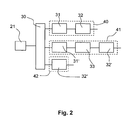
- Fig. 2:
- Schematische Darstellung der Schaltung.
- Fig. 3:
- Detailliertere Darstellung der Schaltung.
- Fig. 4:
- Schematische Darstellung der Schaltung in einer ersten Weiterbildung.
Show it:
- Fig. 1:
- Arrangement with device and vacuum component.
- Fig. 2:
- Schematic representation of the circuit.
- 3:
- Detailed representation of the circuit.
- 4:
- Schematic representation of the circuit in a first embodiment.
In
In dem hier betrachteten Beispiel ist der Steckverbinder 21 eines Gerät 2 mittels einer Anschlussleitung 4 mit dem Steuergerät verbunden. Dieses Gerät weist ein Bedienfeld 23 und ein Anzeigefeld 22 auf. Das Anzeigefeld, beispielsweise ein Display, dient zur Anzeige von aus dem Steuergerät ausgelesenen Werten. Bei diesen handelt es sich beispielsweise um Angaben zur Drehzahl, Leistungsaufnahme, Temperatur und dergleichen mehr. Über das Bedienfeld erfolgt die Eingabe von Werten, die dann an das Steuergerät übergeben werden. Beispielsweise können Parameter gesetzt werden, wie Leerlaufdrehzahl und dergleichen. Anzeigefeld und Bedienfeld können auch integriert in Form eines Touchscreens gestaltet sein.In the example considered here, the
In
Für den inneren Aufbau der Signalverarbeitungseinheiten gibt es verschiedene Möglichkeiten. Diese Möglichkeiten sind in
Die Signalverarbeitungseinheit 40 umfasst einen mit der Weiche verbundenen Treiber 31. Treiber bezeichnet an dieser und den folgenden Stellen dieses Textes nicht nur eine elektrische Signalanpassung, sondern auch eine Trennung, beispielsweise galvanisch, oder die Umsetzung auf andere Signalformen, beispielsweise optisch oder per Funk, wobei Trennung und Umsetzung auch zusammen angewendet sein können. Mit dem Treiber ist ein Interpreter 32 verbunden. Ein Interpreter ist beispielsweise ein Mikrocontroller oder ein vergleichbares Bauteil wie ASIC (Application Specific Integrated Circuit), CPLD (Complex Programmable Logic Device) oder FPGA (Field Programmable Gate Array). Er kann zudem in verschiedenen Stufen Unterinstanzen enthalten, beispielsweise integrierte Controller, die den CAN-Datenverkehr (Controller Area Network) auf Telegrammebene abhandeln, während die Telegramme zu Protokollen in der höheren Instanz zusammengefaßt und behandelt werden.The
Die Signalverarbeitungseinheit 41 umfasst zusätzlich einen zwischen Treiber 31' und Interpreter 32' angeordneten UART (Universal Asynchronous Receiver Transmitter) 33, dessen Funktion ist, einen seriellen digitalen Datenstrom aufzubauen.The
Die Signalverarbeitungseinheit 42 umfasst einen Interpreter 32".The
Die Interpreter 32, 32' und 32" sind mit den weiteren Bestandteilen der Elektronik des Geräts verbunden.The
Der Steckverbinder 21 weist mehrere Kontakte 221 auf. Diese Kontakte sind in Kontaktgruppen 222 und 223 eingeteilt, wobei die Kontaktgruppen mit verschiedenen elektronischen Bestandteilen des Geräts in Verbindung stehen.The
Die Kontaktgruppe 223 ist mit einer elektronischen Komponente 64 des Geräte verbunden, beispielsweise einem Schaltkreis zur Verteilung von Betriebsspannung oder ähnliches.The
Die Kontaktgruppe 222 ist mit der Weiche 30 verbunden, welche ihrerseits an die Signalverarbeitungseinheiten 40, 41 und 42 angeschlossen ist. Die Signalverarbeitungseinheiten stehen in Kontakt mit der Verarbeitungseinheit 60. Im gezeigten Beispiel wertet diese das Bedienfeld aus und steuert das Anzeigefeld an, wofür eine Bedienfeldzuleitung 61 und eine Anzeigefeldzuleitung 62 vorgesehen sind.The
Die Weiche 30 weist Schalter 301, 302 und 303 auf. Mit diesen werden die Zuleitungen zwischen den Kontakten und der Weiche mit den Zuleitungen zwischen Weiche und der gewünschten Signalverarbeitungseinheit verbunden. Eine Umschaltung der Schalter bewirkt somit die Auswahl einer Signalverarbeitungseinheit, die dann mit der Kontaktgruppe 222 in Verbindung steht. Die Erfindung erlaubt es daher, dass die Verarbeitungseinheit des Geräts über einen einzigen Steckverbinder wahlweise mit unterschiedlichen Standards mit einem externen Gerät, beispielsweise dem Steuergerät 10, kommuniziert. Beispielsweise ermöglicht sie die Umschaltung zwischen CAN-Schnittstelle und RS485.The
Die Umschaltung der Schalter wird von einer Schalteinheit 304 bewirkt. Die Schalteinheit kann einen oder mehrere Wege der Weiche freischalten. Die Entscheidung hierüber kann per Hand durch den Benutzer es Geräts erfolgen oder über einen Bestandteil der Elektronik des Geräts, beispielsweise einen Mikrocontroller, der hierfür verschiedene Verfahren heranziehen kann, beispielsweise zyklisches Umschalten der Weiche oder Lauschen auf allen Wegen der Weiche parallel, bis passende Signale gefunden sind. Im gezeigten Beispiel ist eine Steuerleitung 63 zwischen Schalteinheit 304 und Verarbeitungseinheit 60 vorgesehen, über die diese die Umschaltung veranlasst. Um eine automatische Umschaltung zu erreichen, ist eine Zuordnungseinheit 50 an die Kontaktgruppe 222 angeschlossen. Diese ist so gestaltet, dass sie die an den Kontakten der Kontaktgruppe 222 anliegenden Pegel erkennt, beispielsweise solche, die für eine serielle Kommunikation charakterisch sind, und daraus die zu verbindende Signalverarbeitungseinheit 40, 41 oder 42 bestimmt, beispielsweise die für serielle Kommunikation ausgelegte Signalverarbeitungseinheit. Zwischen Zuordnungseinheit und Schalteinheit ist eine Verbindung vorgesehen, über die die Zuordnungseinheit die Umschaltung der Weiche veranlasst.The switching of the switches is effected by a
Die an dem Gerät 2 gezeigte Gestaltung des Steckverbinders und der mit ihm verbundenen Elektronik kann vorteilhaft auf einen der Anschlüsse 11 und 12 des Steuergeräts 10 angewandt werden. Die Anwendung erlaubt dort insbesondere zu einer Verringerung der Anzahl der Anschlüsse. Die Schaltungen gemäß
Claims (7)
Applications Claiming Priority (1)
| Application Number | Priority Date | Filing Date | Title |
|---|---|---|---|
| DE102008061435A DE102008061435A1 (en) | 2008-12-10 | 2008-12-10 | Device connectable to a vacuum pump |
Publications (3)
| Publication Number | Publication Date |
|---|---|
| EP2196670A2 true EP2196670A2 (en) | 2010-06-16 |
| EP2196670A3 EP2196670A3 (en) | 2015-10-21 |
| EP2196670B1 EP2196670B1 (en) | 2017-07-19 |
Family
ID=42104566
Family Applications (1)
| Application Number | Title | Priority Date | Filing Date |
|---|---|---|---|
| EP09014530.1A Active EP2196670B1 (en) | 2008-12-10 | 2009-11-20 | Device which can be connected with a vacuum component |
Country Status (2)
| Country | Link |
|---|---|
| EP (1) | EP2196670B1 (en) |
| DE (1) | DE102008061435A1 (en) |
Cited By (1)
| Publication number | Priority date | Publication date | Assignee | Title |
|---|---|---|---|---|
| EP3660317A1 (en) * | 2018-11-28 | 2020-06-03 | Pfeiffer Vacuum Gmbh | Vacuum device |
Families Citing this family (1)
| Publication number | Priority date | Publication date | Assignee | Title |
|---|---|---|---|---|
| DE102013106474A1 (en) * | 2013-06-20 | 2014-12-24 | Pfeiffer Vacuum Gmbh | Arrangement with a vacuum device and method for detecting data communicated in a communication line between a vacuum device and a central control device |
Family Cites Families (3)
| Publication number | Priority date | Publication date | Assignee | Title |
|---|---|---|---|---|
| DE4237971B4 (en) * | 1992-11-11 | 2004-05-06 | Unaxis Deutschland Holding Gmbh | Vacuum pump with converter |
| US7401162B2 (en) * | 2003-07-22 | 2008-07-15 | Psion Teklogix Inc. | Multi-functional port |
| DE102006036493A1 (en) * | 2006-08-04 | 2008-02-21 | Oerlikon Leybold Vacuum Gmbh | vacuum pump |
-
2008
- 2008-12-10 DE DE102008061435A patent/DE102008061435A1/en not_active Ceased
-
2009
- 2009-11-20 EP EP09014530.1A patent/EP2196670B1/en active Active
Cited By (1)
| Publication number | Priority date | Publication date | Assignee | Title |
|---|---|---|---|---|
| EP3660317A1 (en) * | 2018-11-28 | 2020-06-03 | Pfeiffer Vacuum Gmbh | Vacuum device |
Also Published As
| Publication number | Publication date |
|---|---|
| DE102008061435A1 (en) | 2010-06-17 |
| EP2196670B1 (en) | 2017-07-19 |
| EP2196670A3 (en) | 2015-10-21 |
Similar Documents
| Publication | Publication Date | Title |
|---|---|---|
| EP1168271B1 (en) | Field bus coupling system for actuators or sensors | |
| EP3127192B1 (en) | Modular plug connector | |
| EP1840682B1 (en) | Electrical field device and extension module for plugging in to said electric field device | |
| EP3262907B1 (en) | Modular field device connection unit | |
| EP3071842B1 (en) | Valve assembly and fluid system | |
| EP1931883A1 (en) | Electropneumatic module system composed of individual modules put in a row | |
| DE10031964C1 (en) | Electric power switch with integrated microprocessor control has wired interface coupled to field bus system and data input/output device coupled to current supply lines | |
| EP3647600B1 (en) | Identification of an electrically connected peripheral | |
| DE102019127195A1 (en) | Modular interface system for connecting a control device and field devices | |
| EP2196670B1 (en) | Device which can be connected with a vacuum component | |
| EP3586201B1 (en) | Front adapter for connecting to a control device and automation system | |
| DE102005043489A1 (en) | Field device for e.g. data processing application, has converting unit, which converts binary signal representing data bit stream to periodic frequency shift keying signal using microcontroller | |
| DE102010030821A1 (en) | Method and device for commissioning field devices, in particular HART field devices in multidrop operating mode | |
| EP3617520A1 (en) | Vacuum device, accessory unit and system | |
| DE102018131685A1 (en) | Field device adapter for wireless data transmission | |
| DE102005043488A1 (en) | Field device for data processing application, has microcontroller, whose connection is actively switched for input of logical connection in related level and is switched for input of inverse logical connection as high impedance input | |
| EP3350455A1 (en) | Valve control means, and method for operating a valve control means | |
| EP3097751B1 (en) | Control technology connection adapter system | |
| EP3114771A1 (en) | Device for the transmission of signals | |
| DE102013000944A1 (en) | Steering wheel with improved interface to a finger navigation module | |
| BE1026569B1 (en) | Control and data transmission system to support various communication protocols and an adapter module | |
| EP1573211B1 (en) | Device for the status diagnosis of a hydraulic component in particular a hydraulic cylinder | |
| DE102010038459A1 (en) | Safety system, has safety module comprising system interface for direct contacting and communication with group protection unit, and load branch comprising another system interface for direct communication with safety module | |
| WO2020249322A1 (en) | Automation field device | |
| EP0896264B1 (en) | Programmable interface for technical systems in a building |
Legal Events
| Date | Code | Title | Description |
|---|---|---|---|
| PUAI | Public reference made under article 153(3) epc to a published international application that has entered the european phase |
Free format text: ORIGINAL CODE: 0009012 |
|
| AK | Designated contracting states |
Kind code of ref document: A2 Designated state(s): AT BE BG CH CY CZ DE DK EE ES FI FR GB GR HR HU IE IS IT LI LT LU LV MC MK MT NL NO PL PT RO SE SI SK SM TR |
|
| AX | Request for extension of the european patent |
Extension state: AL BA RS |
|
| PUAL | Search report despatched |
Free format text: ORIGINAL CODE: 0009013 |
|
| AK | Designated contracting states |
Kind code of ref document: A3 Designated state(s): AT BE BG CH CY CZ DE DK EE ES FI FR GB GR HR HU IE IS IT LI LT LU LV MC MK MT NL NO PL PT RO SE SI SK SM TR |
|
| AX | Request for extension of the european patent |
Extension state: AL BA RS |
|
| RIC1 | Information provided on ipc code assigned before grant |
Ipc: F04B 37/14 20060101AFI20150914BHEP |
|
| 17P | Request for examination filed |
Effective date: 20160421 |
|
| RBV | Designated contracting states (corrected) |
Designated state(s): AT BE BG CH CY CZ DE DK EE ES FI FR GB GR HR HU IE IS IT LI LT LU LV MC MK MT NL NO PL PT RO SE SI SK SM TR |
|
| 17Q | First examination report despatched |
Effective date: 20160818 |
|
| GRAP | Despatch of communication of intention to grant a patent |
Free format text: ORIGINAL CODE: EPIDOSNIGR1 |
|
| INTG | Intention to grant announced |
Effective date: 20170210 |
|
| GRAS | Grant fee paid |
Free format text: ORIGINAL CODE: EPIDOSNIGR3 |
|
| GRAA | (expected) grant |
Free format text: ORIGINAL CODE: 0009210 |
|
| AK | Designated contracting states |
Kind code of ref document: B1 Designated state(s): AT BE BG CH CY CZ DE DK EE ES FI FR GB GR HR HU IE IS IT LI LT LU LV MC MK MT NL NO PL PT RO SE SI SK SM TR |
|
| REG | Reference to a national code |
Ref country code: GB Ref legal event code: FG4D Free format text: NOT ENGLISH |
|
| REG | Reference to a national code |
Ref country code: CH Ref legal event code: EP |
|
| REG | Reference to a national code |
Ref country code: IE Ref legal event code: FG4D Free format text: LANGUAGE OF EP DOCUMENT: GERMAN |
|
| REG | Reference to a national code |
Ref country code: AT Ref legal event code: REF Ref document number: 910672 Country of ref document: AT Kind code of ref document: T Effective date: 20170815 |
|
| REG | Reference to a national code |
Ref country code: DE Ref legal event code: R096 Ref document number: 502009014164 Country of ref document: DE |
|
| REG | Reference to a national code |
Ref country code: FR Ref legal event code: PLFP Year of fee payment: 9 |
|
| REG | Reference to a national code |
Ref country code: NL Ref legal event code: MP Effective date: 20170719 |
|
| REG | Reference to a national code |
Ref country code: LT Ref legal event code: MG4D |
|
| PG25 | Lapsed in a contracting state [announced via postgrant information from national office to epo] |
Ref country code: NL Free format text: LAPSE BECAUSE OF FAILURE TO SUBMIT A TRANSLATION OF THE DESCRIPTION OR TO PAY THE FEE WITHIN THE PRESCRIBED TIME-LIMIT Effective date: 20170719 Ref country code: FI Free format text: LAPSE BECAUSE OF FAILURE TO SUBMIT A TRANSLATION OF THE DESCRIPTION OR TO PAY THE FEE WITHIN THE PRESCRIBED TIME-LIMIT Effective date: 20170719 Ref country code: HR Free format text: LAPSE BECAUSE OF FAILURE TO SUBMIT A TRANSLATION OF THE DESCRIPTION OR TO PAY THE FEE WITHIN THE PRESCRIBED TIME-LIMIT Effective date: 20170719 Ref country code: LT Free format text: LAPSE BECAUSE OF FAILURE TO SUBMIT A TRANSLATION OF THE DESCRIPTION OR TO PAY THE FEE WITHIN THE PRESCRIBED TIME-LIMIT Effective date: 20170719 Ref country code: NO Free format text: LAPSE BECAUSE OF FAILURE TO SUBMIT A TRANSLATION OF THE DESCRIPTION OR TO PAY THE FEE WITHIN THE PRESCRIBED TIME-LIMIT Effective date: 20171019 Ref country code: SE Free format text: LAPSE BECAUSE OF FAILURE TO SUBMIT A TRANSLATION OF THE DESCRIPTION OR TO PAY THE FEE WITHIN THE PRESCRIBED TIME-LIMIT Effective date: 20170719 |
|
| PG25 | Lapsed in a contracting state [announced via postgrant information from national office to epo] |
Ref country code: ES Free format text: LAPSE BECAUSE OF FAILURE TO SUBMIT A TRANSLATION OF THE DESCRIPTION OR TO PAY THE FEE WITHIN THE PRESCRIBED TIME-LIMIT Effective date: 20170719 Ref country code: GR Free format text: LAPSE BECAUSE OF FAILURE TO SUBMIT A TRANSLATION OF THE DESCRIPTION OR TO PAY THE FEE WITHIN THE PRESCRIBED TIME-LIMIT Effective date: 20171020 Ref country code: IS Free format text: LAPSE BECAUSE OF FAILURE TO SUBMIT A TRANSLATION OF THE DESCRIPTION OR TO PAY THE FEE WITHIN THE PRESCRIBED TIME-LIMIT Effective date: 20171119 Ref country code: LV Free format text: LAPSE BECAUSE OF FAILURE TO SUBMIT A TRANSLATION OF THE DESCRIPTION OR TO PAY THE FEE WITHIN THE PRESCRIBED TIME-LIMIT Effective date: 20170719 Ref country code: BG Free format text: LAPSE BECAUSE OF FAILURE TO SUBMIT A TRANSLATION OF THE DESCRIPTION OR TO PAY THE FEE WITHIN THE PRESCRIBED TIME-LIMIT Effective date: 20171019 Ref country code: PL Free format text: LAPSE BECAUSE OF FAILURE TO SUBMIT A TRANSLATION OF THE DESCRIPTION OR TO PAY THE FEE WITHIN THE PRESCRIBED TIME-LIMIT Effective date: 20170719 |
|
| REG | Reference to a national code |
Ref country code: DE Ref legal event code: R097 Ref document number: 502009014164 Country of ref document: DE |
|
| PG25 | Lapsed in a contracting state [announced via postgrant information from national office to epo] |
Ref country code: RO Free format text: LAPSE BECAUSE OF FAILURE TO SUBMIT A TRANSLATION OF THE DESCRIPTION OR TO PAY THE FEE WITHIN THE PRESCRIBED TIME-LIMIT Effective date: 20170719 Ref country code: DK Free format text: LAPSE BECAUSE OF FAILURE TO SUBMIT A TRANSLATION OF THE DESCRIPTION OR TO PAY THE FEE WITHIN THE PRESCRIBED TIME-LIMIT Effective date: 20170719 |
|
| PLBE | No opposition filed within time limit |
Free format text: ORIGINAL CODE: 0009261 |
|
| STAA | Information on the status of an ep patent application or granted ep patent |
Free format text: STATUS: NO OPPOSITION FILED WITHIN TIME LIMIT |
|
| PG25 | Lapsed in a contracting state [announced via postgrant information from national office to epo] |
Ref country code: SK Free format text: LAPSE BECAUSE OF FAILURE TO SUBMIT A TRANSLATION OF THE DESCRIPTION OR TO PAY THE FEE WITHIN THE PRESCRIBED TIME-LIMIT Effective date: 20170719 Ref country code: EE Free format text: LAPSE BECAUSE OF FAILURE TO SUBMIT A TRANSLATION OF THE DESCRIPTION OR TO PAY THE FEE WITHIN THE PRESCRIBED TIME-LIMIT Effective date: 20170719 Ref country code: SM Free format text: LAPSE BECAUSE OF FAILURE TO SUBMIT A TRANSLATION OF THE DESCRIPTION OR TO PAY THE FEE WITHIN THE PRESCRIBED TIME-LIMIT Effective date: 20170719 |
|
| 26N | No opposition filed |
Effective date: 20180420 |
|
| PG25 | Lapsed in a contracting state [announced via postgrant information from national office to epo] |
Ref country code: MC Free format text: LAPSE BECAUSE OF FAILURE TO SUBMIT A TRANSLATION OF THE DESCRIPTION OR TO PAY THE FEE WITHIN THE PRESCRIBED TIME-LIMIT Effective date: 20170719 |
|
| PG25 | Lapsed in a contracting state [announced via postgrant information from national office to epo] |
Ref country code: CH Free format text: LAPSE BECAUSE OF NON-PAYMENT OF DUE FEES Effective date: 20171130 Ref country code: LI Free format text: LAPSE BECAUSE OF NON-PAYMENT OF DUE FEES Effective date: 20171130 |
|
| PG25 | Lapsed in a contracting state [announced via postgrant information from national office to epo] |
Ref country code: LU Free format text: LAPSE BECAUSE OF NON-PAYMENT OF DUE FEES Effective date: 20171120 Ref country code: SI Free format text: LAPSE BECAUSE OF FAILURE TO SUBMIT A TRANSLATION OF THE DESCRIPTION OR TO PAY THE FEE WITHIN THE PRESCRIBED TIME-LIMIT Effective date: 20170719 |
|
| REG | Reference to a national code |
Ref country code: BE Ref legal event code: MM Effective date: 20171130 |
|
| REG | Reference to a national code |
Ref country code: IE Ref legal event code: MM4A |
|
| PG25 | Lapsed in a contracting state [announced via postgrant information from national office to epo] |
Ref country code: MT Free format text: LAPSE BECAUSE OF FAILURE TO SUBMIT A TRANSLATION OF THE DESCRIPTION OR TO PAY THE FEE WITHIN THE PRESCRIBED TIME-LIMIT Effective date: 20170719 |
|
| PG25 | Lapsed in a contracting state [announced via postgrant information from national office to epo] |
Ref country code: IE Free format text: LAPSE BECAUSE OF NON-PAYMENT OF DUE FEES Effective date: 20171120 |
|
| PG25 | Lapsed in a contracting state [announced via postgrant information from national office to epo] |
Ref country code: BE Free format text: LAPSE BECAUSE OF NON-PAYMENT OF DUE FEES Effective date: 20171130 |
|
| REG | Reference to a national code |
Ref country code: AT Ref legal event code: MM01 Ref document number: 910672 Country of ref document: AT Kind code of ref document: T Effective date: 20171120 |
|
| PG25 | Lapsed in a contracting state [announced via postgrant information from national office to epo] |
Ref country code: AT Free format text: LAPSE BECAUSE OF NON-PAYMENT OF DUE FEES Effective date: 20171120 |
|
| PG25 | Lapsed in a contracting state [announced via postgrant information from national office to epo] |
Ref country code: HU Free format text: LAPSE BECAUSE OF FAILURE TO SUBMIT A TRANSLATION OF THE DESCRIPTION OR TO PAY THE FEE WITHIN THE PRESCRIBED TIME-LIMIT; INVALID AB INITIO Effective date: 20091120 |
|
| PG25 | Lapsed in a contracting state [announced via postgrant information from national office to epo] |
Ref country code: CY Free format text: LAPSE BECAUSE OF NON-PAYMENT OF DUE FEES Effective date: 20170719 |
|
| PG25 | Lapsed in a contracting state [announced via postgrant information from national office to epo] |
Ref country code: MK Free format text: LAPSE BECAUSE OF FAILURE TO SUBMIT A TRANSLATION OF THE DESCRIPTION OR TO PAY THE FEE WITHIN THE PRESCRIBED TIME-LIMIT Effective date: 20170719 |
|
| PG25 | Lapsed in a contracting state [announced via postgrant information from national office to epo] |
Ref country code: TR Free format text: LAPSE BECAUSE OF FAILURE TO SUBMIT A TRANSLATION OF THE DESCRIPTION OR TO PAY THE FEE WITHIN THE PRESCRIBED TIME-LIMIT Effective date: 20170719 |
|
| PG25 | Lapsed in a contracting state [announced via postgrant information from national office to epo] |
Ref country code: PT Free format text: LAPSE BECAUSE OF FAILURE TO SUBMIT A TRANSLATION OF THE DESCRIPTION OR TO PAY THE FEE WITHIN THE PRESCRIBED TIME-LIMIT Effective date: 20170719 |
|
| PGFP | Annual fee paid to national office [announced via postgrant information from national office to epo] |
Ref country code: GB Payment date: 20231123 Year of fee payment: 15 |
|
| PGFP | Annual fee paid to national office [announced via postgrant information from national office to epo] |
Ref country code: IT Payment date: 20231124 Year of fee payment: 15 Ref country code: FR Payment date: 20231120 Year of fee payment: 15 Ref country code: CZ Payment date: 20231110 Year of fee payment: 15 |
|
| PGFP | Annual fee paid to national office [announced via postgrant information from national office to epo] |
Ref country code: DE Payment date: 20240129 Year of fee payment: 15 |