EP2193275B1 - Two way accumulator programmable valve pump - Google Patents
Two way accumulator programmable valve pump Download PDFInfo
- Publication number
- EP2193275B1 EP2193275B1 EP08835694.4A EP08835694A EP2193275B1 EP 2193275 B1 EP2193275 B1 EP 2193275B1 EP 08835694 A EP08835694 A EP 08835694A EP 2193275 B1 EP2193275 B1 EP 2193275B1
- Authority
- EP
- European Patent Office
- Prior art keywords
- accumulator
- diaphragm
- outlet
- infusate
- valve
- Prior art date
- Legal status (The legal status is an assumption and is not a legal conclusion. Google has not performed a legal analysis and makes no representation as to the accuracy of the status listed.)
- Active
Links
- 239000012530 fluid Substances 0.000 claims description 42
- 238000004891 communication Methods 0.000 claims description 16
- 125000006850 spacer group Chemical group 0.000 claims description 13
- 238000001802 infusion Methods 0.000 claims description 10
- 230000004888 barrier function Effects 0.000 claims description 3
- 230000000284 resting effect Effects 0.000 claims description 3
- 230000001351 cycling effect Effects 0.000 claims description 2
- 239000007789 gas Substances 0.000 description 19
- 238000013461 design Methods 0.000 description 16
- 238000005086 pumping Methods 0.000 description 9
- 230000002411 adverse Effects 0.000 description 6
- 239000003814 drug Substances 0.000 description 6
- 229940079593 drug Drugs 0.000 description 5
- 230000000694 effects Effects 0.000 description 4
- XKRFYHLGVUSROY-UHFFFAOYSA-N Argon Chemical compound [Ar] XKRFYHLGVUSROY-UHFFFAOYSA-N 0.000 description 2
- IJGRMHOSHXDMSA-UHFFFAOYSA-N Atomic nitrogen Chemical compound N#N IJGRMHOSHXDMSA-UHFFFAOYSA-N 0.000 description 2
- 230000015556 catabolic process Effects 0.000 description 2
- 238000006731 degradation reaction Methods 0.000 description 2
- 238000010586 diagram Methods 0.000 description 2
- 239000007788 liquid Substances 0.000 description 2
- 238000004519 manufacturing process Methods 0.000 description 2
- 239000000463 material Substances 0.000 description 2
- 238000000034 method Methods 0.000 description 2
- 238000003466 welding Methods 0.000 description 2
- 240000007817 Olea europaea Species 0.000 description 1
- RTAQQCXQSZGOHL-UHFFFAOYSA-N Titanium Chemical compound [Ti] RTAQQCXQSZGOHL-UHFFFAOYSA-N 0.000 description 1
- 238000009825 accumulation Methods 0.000 description 1
- 239000000853 adhesive Substances 0.000 description 1
- 230000001070 adhesive effect Effects 0.000 description 1
- 229910052786 argon Inorganic materials 0.000 description 1
- 230000001580 bacterial effect Effects 0.000 description 1
- 238000001514 detection method Methods 0.000 description 1
- 238000012377 drug delivery Methods 0.000 description 1
- 239000003640 drug residue Substances 0.000 description 1
- 238000005538 encapsulation Methods 0.000 description 1
- 238000005516 engineering process Methods 0.000 description 1
- 238000001914 filtration Methods 0.000 description 1
- 239000001307 helium Substances 0.000 description 1
- 229910052734 helium Inorganic materials 0.000 description 1
- SWQJXJOGLNCZEY-UHFFFAOYSA-N helium atom Chemical compound [He] SWQJXJOGLNCZEY-UHFFFAOYSA-N 0.000 description 1
- 239000007943 implant Substances 0.000 description 1
- 239000011261 inert gas Substances 0.000 description 1
- 238000003780 insertion Methods 0.000 description 1
- 230000037431 insertion Effects 0.000 description 1
- 238000002955 isolation Methods 0.000 description 1
- 150000002605 large molecules Chemical class 0.000 description 1
- 230000033001 locomotion Effects 0.000 description 1
- 229920002521 macromolecule Polymers 0.000 description 1
- 239000012528 membrane Substances 0.000 description 1
- 229910052751 metal Inorganic materials 0.000 description 1
- 239000002184 metal Substances 0.000 description 1
- 239000000203 mixture Substances 0.000 description 1
- 229910052757 nitrogen Inorganic materials 0.000 description 1
- 238000005457 optimization Methods 0.000 description 1
- 239000002245 particle Substances 0.000 description 1
- 230000002093 peripheral effect Effects 0.000 description 1
- 230000001225 therapeutic effect Effects 0.000 description 1
- 239000010936 titanium Substances 0.000 description 1
- 229910052719 titanium Inorganic materials 0.000 description 1
- 238000005406 washing Methods 0.000 description 1
Images


Classifications
-
- G—PHYSICS
- G01—MEASURING; TESTING
- G01F—MEASURING VOLUME, VOLUME FLOW, MASS FLOW OR LIQUID LEVEL; METERING BY VOLUME
- G01F11/00—Apparatus requiring external operation adapted at each repeated and identical operation to measure and separate a predetermined volume of fluid or fluent solid material from a supply or container, without regard to weight, and to deliver it
- G01F11/02—Apparatus requiring external operation adapted at each repeated and identical operation to measure and separate a predetermined volume of fluid or fluent solid material from a supply or container, without regard to weight, and to deliver it with measuring chambers which expand or contract during measurement
- G01F11/08—Apparatus requiring external operation adapted at each repeated and identical operation to measure and separate a predetermined volume of fluid or fluent solid material from a supply or container, without regard to weight, and to deliver it with measuring chambers which expand or contract during measurement of the diaphragm or bellows type
- G01F11/086—Apparatus requiring external operation adapted at each repeated and identical operation to measure and separate a predetermined volume of fluid or fluent solid material from a supply or container, without regard to weight, and to deliver it with measuring chambers which expand or contract during measurement of the diaphragm or bellows type using an auxiliary pressure to cooperate with the diaphragm or bellows
-
- A—HUMAN NECESSITIES
- A61—MEDICAL OR VETERINARY SCIENCE; HYGIENE
- A61M—DEVICES FOR INTRODUCING MEDIA INTO, OR ONTO, THE BODY; DEVICES FOR TRANSDUCING BODY MEDIA OR FOR TAKING MEDIA FROM THE BODY; DEVICES FOR PRODUCING OR ENDING SLEEP OR STUPOR
- A61M5/00—Devices for bringing media into the body in a subcutaneous, intra-vascular or intramuscular way; Accessories therefor, e.g. filling or cleaning devices, arm-rests
- A61M5/14—Infusion devices, e.g. infusing by gravity; Blood infusion; Accessories therefor
- A61M5/142—Pressure infusion, e.g. using pumps
- A61M5/14244—Pressure infusion, e.g. using pumps adapted to be carried by the patient, e.g. portable on the body
- A61M5/14276—Pressure infusion, e.g. using pumps adapted to be carried by the patient, e.g. portable on the body specially adapted for implantation
-
- A—HUMAN NECESSITIES
- A61—MEDICAL OR VETERINARY SCIENCE; HYGIENE
- A61M—DEVICES FOR INTRODUCING MEDIA INTO, OR ONTO, THE BODY; DEVICES FOR TRANSDUCING BODY MEDIA OR FOR TAKING MEDIA FROM THE BODY; DEVICES FOR PRODUCING OR ENDING SLEEP OR STUPOR
- A61M5/00—Devices for bringing media into the body in a subcutaneous, intra-vascular or intramuscular way; Accessories therefor, e.g. filling or cleaning devices, arm-rests
- A61M5/14—Infusion devices, e.g. infusing by gravity; Blood infusion; Accessories therefor
- A61M5/142—Pressure infusion, e.g. using pumps
- A61M5/145—Pressure infusion, e.g. using pumps using pressurised reservoirs, e.g. pressurised by means of pistons
- A61M5/14586—Pressure infusion, e.g. using pumps using pressurised reservoirs, e.g. pressurised by means of pistons pressurised by means of a flexible diaphragm
-
- A—HUMAN NECESSITIES
- A61—MEDICAL OR VETERINARY SCIENCE; HYGIENE
- A61M—DEVICES FOR INTRODUCING MEDIA INTO, OR ONTO, THE BODY; DEVICES FOR TRANSDUCING BODY MEDIA OR FOR TAKING MEDIA FROM THE BODY; DEVICES FOR PRODUCING OR ENDING SLEEP OR STUPOR
- A61M5/00—Devices for bringing media into the body in a subcutaneous, intra-vascular or intramuscular way; Accessories therefor, e.g. filling or cleaning devices, arm-rests
- A61M5/14—Infusion devices, e.g. infusing by gravity; Blood infusion; Accessories therefor
- A61M5/168—Means for controlling media flow to the body or for metering media to the body, e.g. drip meters, counters ; Monitoring media flow to the body
- A61M5/16804—Flow controllers
- A61M5/16809—Flow controllers by repeated filling and emptying of an intermediate volume
-
- A—HUMAN NECESSITIES
- A61—MEDICAL OR VETERINARY SCIENCE; HYGIENE
- A61M—DEVICES FOR INTRODUCING MEDIA INTO, OR ONTO, THE BODY; DEVICES FOR TRANSDUCING BODY MEDIA OR FOR TAKING MEDIA FROM THE BODY; DEVICES FOR PRODUCING OR ENDING SLEEP OR STUPOR
- A61M5/00—Devices for bringing media into the body in a subcutaneous, intra-vascular or intramuscular way; Accessories therefor, e.g. filling or cleaning devices, arm-rests
- A61M5/14—Infusion devices, e.g. infusing by gravity; Blood infusion; Accessories therefor
- A61M5/142—Pressure infusion, e.g. using pumps
- A61M5/145—Pressure infusion, e.g. using pumps using pressurised reservoirs, e.g. pressurised by means of pistons
- A61M2005/14513—Pressure infusion, e.g. using pumps using pressurised reservoirs, e.g. pressurised by means of pistons with secondary fluid driving or regulating the infusion
-
- A—HUMAN NECESSITIES
- A61—MEDICAL OR VETERINARY SCIENCE; HYGIENE
- A61M—DEVICES FOR INTRODUCING MEDIA INTO, OR ONTO, THE BODY; DEVICES FOR TRANSDUCING BODY MEDIA OR FOR TAKING MEDIA FROM THE BODY; DEVICES FOR PRODUCING OR ENDING SLEEP OR STUPOR
- A61M5/00—Devices for bringing media into the body in a subcutaneous, intra-vascular or intramuscular way; Accessories therefor, e.g. filling or cleaning devices, arm-rests
- A61M5/14—Infusion devices, e.g. infusing by gravity; Blood infusion; Accessories therefor
- A61M5/142—Pressure infusion, e.g. using pumps
- A61M5/145—Pressure infusion, e.g. using pumps using pressurised reservoirs, e.g. pressurised by means of pistons
- A61M5/14586—Pressure infusion, e.g. using pumps using pressurised reservoirs, e.g. pressurised by means of pistons pressurised by means of a flexible diaphragm
- A61M5/14593—Pressure infusion, e.g. using pumps using pressurised reservoirs, e.g. pressurised by means of pistons pressurised by means of a flexible diaphragm the diaphragm being actuated by fluid pressure
Definitions
- This invention is a direct improvement over the technology of U.S. Patent Nos. 4,838,887 and 5,049,141 ,
- Energy efficiency can be achieved by increasing the fixed volume pumped. Increasing the volume pumped can be achieved by increasing the size of the accumulator in diameter and/or height. However, increased accumulator size can create performance degradation of the existing designs. For example, a higher accumulator requires the accumulator diaphragm to deflect further. This increase in deflection creates a corresponding increase in diaphragm spring force.
- An object of this invention is to effect energy efficiency, increase fixed volume pumping and pump performance through a new accumulator design while minimizing the aforesaid adverse effects.
- the new design employs a "Two Way Diaphragm" that deflects in two directions.
- U.S. 5,049,141 to Olive discloses an implantable valve accumulator pump that includes a spacer plate having concentric circumferential grooves which reduces the diaphragm and plate contact area.
- U.S. 5,669,764 to Behringer et al. discloses an integral valve diaphragm pump having first and second rigid layers and a flexible membrane there between, where concave surfaces in the two rigid layers form a pump.
- WO 2006/123329 to Medingo Ltd. discloses methods and systems associated with a disposable dispenser of therapeutic fluid that may be releasably attached to a body and includes a reservoir, a dosing and metering pump, and a fluid delivery tool, where removal of a tape layer from a housing bottom of the dispenser electrically connects a power supply to operative components of the dispenser, exposes an adhesive and a window in the housing, and allows the fluid delivery tool to extend for insertion into the skin.
- U.S. 6,905,479 to Bouchard et al. discloses pumping cartridges for use in pumping systems that include an integrated filter element therein for filtering fluids, for example fluids pumped to the body of a patient in a medical procedure.
- WO 96/41156 to Deka Products Limited Partnership discloses an intravenous-line air-detection system.
- the present invention provides an infusion apparatus comprising a metering assembly that includes a valve accumulator pump, the infusion apparatus being implantable into a living body. More specifically, the invention relates to an infusion apparatus including a valve accumulator pump for such apparatus that delivers precise amounts of medication or other fluid at programmed rates.
- the implantable infusion apparatus includes an infusate reservoir, a metering assembly comprising an accumulator having an inlet, an outlet, a first mechanical stop, and a second mechanical stop, an inlet valve in communication with said infusate reservoir and with said accumulator inlet, and an outlet valve in communication with said accumulator outlet, a diaphragm disposed in said accumulator such that said diaphragm has a resting state position, deflects in a first direction in response to the opening of said inlet valve while said outlet valve is closed to cause infusate to flow into said accumulator from said reservoir, and deflects in a second direction in response to the opening of said outlet valve while said inlet valve is closed to cause said infusate to flow out of said accumulator outlet, wherein said first direction and said second direction are different, a gas chamber containing a pressurized gas, wherein said diaphragm provides a barrier between said pressurized gas and any infusate in said accumulator, and said pressur
- the implantable infusion apparatus further includes a spacer having a concave surface defining said second mechanical stop, said concave surface having an annular groove and a trough in fluid communication with said annular groove and with said inlet and said outlet of said accumulator, a diameter of said annular groove being smaller than a length of said trough and smaller than a distance from said inlet to said outlet, said annular groove is the only annular groove in said spacer, and said annular groove and said trough defining a fluid flow path, wherein the volume of said fluid flow path is equal to or less than about 5% of a total volume of infusate discharged by said accumulator.
- the infusion apparatus of the present invention includes a metering assembly having a programmable valve accumulator pump 30, an infusate reservoir 10 that can be conventional and well-known in the art, and an external programmer 34.
- a programmable valve accumulator pump 30 that can be conventional and well-known in the art
- an external programmer 34 is not necessary; for example, the device could be used in a fixed rate configuration that is never programmed but is preset.
- the reservoir 10 is a sealed housing 14 that contains bellows 16 that includes an internal volume that contains the medicament or other fluid to be infused.
- the reservoir is preferably rechargeable.
- a chamber 20 External of the bellow is a chamber 20 that contains a fluid, such as a two-phase fluid having a significant vapor pressure at normal body pressure so that it compresses the bellows and causes the fluid in the bellows to exit the outlet of the housing 14.
- the outlet communicates with the metering assembly, such as via a bacterial filter 24, the metering assembly generally comprising an accumulator 30 and an inlet valve 26 and an outlet valve 28 in fluid isolation from the inlet valve.
- the metering assembly is electronically controlled in accordance with convention.
- the accumulator 30 includes a housing 50, that together with cap 51 defines a sealed gas chamber 52.
- the cap 51 is attached to the housing 50 by any suitable means, such as laser welding.
- a suitable gas is sealed, under positive pressure, in the gas chamber 52.
- the gas chamber 52 is in fluid communication with diaphragm chamber 57 via a port 55 in the housing 50.
- the bottom surface of the housing 50 is configured and positioned to serve as a mechanical stop for the diaphragm 50 when the diaphragm 50 is in the up (fill) position.
- a faceplate 56 Affixed to the housing 50 is a faceplate 56.
- the edges of the diaphragm 40 are sandwiched between the housing 50 and faceplate 57 as shown, and the assembly is sealed, such as by laser welding.
- the volume between the housing 50 and faceplate 57, containing the diaphragm 40, defines the diaphragm chamber 57.
- the diaphragm 40 thus provides a barrier, separating the gas side (e.g., above the diaphragm) from the fluid side (e.g., below the diaphragm) in the accumulator 30.
- Faceplate 56 also includes a fluid inlet port 58 that provides fluid communication between inlet valve 26 and the diaphragm chamber 57, and fluid outlet port 59 that provides fluid communication between outlet valve 28 and the diaphragm chamber 57.
- a normally closed inlet valve 26 is in fluid communication with the inlet port 58 of the accumulator 30 (and the outlet of the reservoir 10 via line 22).
- a normally closed outlet valve 28 is in fluid communication with the outlet port 59 of the accumulator 30.
- Miniature solenoid valves are suitable.
- the valves 26, 28 are controlled electronically, such as through a module programmed by an external programmer 34 ( Figure 1 ).
- the outlet of the accumulator 30 communicates with a catheter or the like via line 36 that delivers the infusate to the delivery site in the patient in a conventional manner.
- the diaphragm 40 is a circular disk of a thin metal sheet.
- a thin metal sheet Preferably titanium may be used, although other materials also may be suitable as determined by those skilled in the art.
- the disk is selected to have a diameter and thickness of low spring rate over the desired range of deflection.
- the diaphragm acts as a compliant, flexible wall which separates fluid from the environment behind it.
- the upward and downward motions of the diaphragm 40 are limited by the bottom surface of the housing 50, and the top surface of the faceplate 56, each of which serves as a mechanical stop for the diaphragm, depending on whether the diaphragm chamber 57 is filled with infusate or is empty of infusate.
- these surfaces are provided with a shallow concave profile manufactured into its diaphragm contact surface.
- This surface acts as a contour stop for the diaphragm.
- Dimensions of the contour are chosen to match the general profile of the diaphragm when it is deflected or biased by a predetermined fixed volume.
- This predetermined fixed volume is the volume desired to be metered from the accumulator (e.g., 2 ⁇ l).
- the Two Way Diaphragm permits the optimization of accumulator size and energy utilization to increase fixed volume pumping and to conserve battery energy.
- the first step in the Figure 2 pumping cycle shows the accumulator 30 in a state where both the inlet valve 26 and the outlet valve 28 are closed, and the diaphragm chamber 57 of the accumulator is empty (i.e., devoid of infusate fluid).
- the diaphragm 40 is firmly held against the spacer 70 by the gas and is substantially flat; it is not being urged or deflected in either an upward or downward direction (it is noted that the accumulator pressure is generally less than the reservoir pressure and diaphragm spring force and greater than the catheter outlet pressure).
- the second step in the cycle shows the accumulator 30 after the inlet valve 26 has been opened (maintaining the outlet valve 28 closed). The infusate fluid overcomes the bias of the pressurized gas against the diaphragm 40, and deflects the diaphragm 40 upward, thereby filling the diaphragm chamber 57 with fluid from the reservoir 10.
- the third step in the cycle is the closing of the inlet valve 26 once the diaphragm chamber 57 has been filled to its fixed or desired volume.
- the fourth step in the cycle is the opening of the outlet valve 28 (while maintaining the inlet valve 26 in the closed position) to empty the diaphragm chamber 57 through the catheter 36, wherein the diaphragm 40 deflects downward as a result of the bias from the gas pressure in the gas chamber 52 and in the gas side of the diaphragm chamber 57.
- the diaphragm 40 deflects in a first direction during the filling operation of the accumulator 30, as infusate fluid under pressure forces the diaphragm upwards against the mechanical stop of the bottom surface of the housing 50, overcoming the pressure exerted by the gas in the accumulator.
- the diaphragm also deflects in a second direction during the emptying of the accumulator 30, past its flat, resting point position, as the pressurized gas in the accumulator forces the diaphragm downward against the mechanical stop of the top surface of the faceplate 56.
- the two-way deflection allows twice the volume to be delivered during a single pumping cycle compared to conventional designs, using the substantially same amount of energy.
- the first and second directions of deflection of the diaphragm are opposite directions.
- the accumulator 30 thus stores and discharges predetermined volume spikes of infusate at a frequency defined by the cycling rate of the inlet and outlet valves.
- Suitable gasses include inert gases such as argon, helium and nitrogen, mixtures thereof, and air.
- FIGS. 5A and 5B of the '887 patent illustrate the details of the spacer plate utilized between the medication accumulation chamber and the accumulator valves.
- the continuous contoured surface desirable to use on the gas-filled side of the diaphragm is undesirable on the fluid side. Intimate contact of two relatively flat surfaces with a liquid interface will create flow restrictions when the accumulator is emptied as the plates move toward each other and during filling when the plates move away from each other. This adverse effect was designed to be overcome by the addition of a checkerboard groove pattern as illustrated in FIG. 5B of the '887 patent. Additionally, a circumferential groove was incorporated in the design to establish fluid communication between the inlet and the outlet valves. Objects of the design were to: permit complete free flow of fluid underneath the flattened diaphragm; assist in washing of areas which might otherwise remain stagnant, and; maintain the accumulator dead volume at a minimum level.
- U.S. Patent No. 5,049,141 introduced an improved spacer plate design as illustrated in Figs 5A and 5B of that patent, the purpose of which was to reduce the diaphragm contact area with the plate. It was found that the prior art's use of a checkerboard groove provided too much surface contact area and therefore large molecule drugs could be crushed at the plate and diaphragm contact points resulting in the creation of drug residue. The prior art checkerboard design also created areas where the drug could stagnate and particles and air bubbles could be trapped.
- the '141 patent introduced an improved spacer plate design utilizing concentric circumferential grooves to establish fluid communication between the inlet and outlet valves and for fluid communication with the trough and a design that would reduce the diaphragm and plate contact area.
- the spacer 70 in accordance with certain embodiments of the present invention improves upon the prior art with a design that maximizes the wash out of fluid and minimizes dead volume.
- Channels in the spacer are designed to create a flow path that allows the fluid to exit the accumulator quickly (e.g., the channel flow restriction is kept large enough to allow the accumulator to empty in a short period of time). It was found that the multiple annular grooves of the prior art provided multiple sites for stagnant fluid and air encapsulation resulting in dead volume and a degradation of pumping accuracy.
- the spacer 70 of the present invention includes an annular groove 54 intersected by (and thereby in fluid communication with) a trough 53 connecting the inlet and outlet valves wherein the volume of the space created by the annular and trough grooves permits the dead volume in the grooves and outlets to be equal to or less than about 5% of the total volume discharged by the accumulator.
- a single annular groove 54 is provided, and it is interior to the inlet and outlet apertures respectively communicating with the inlet and outlet valves, such that the diameter of the annular groove 54 is smaller than the length of the trough 53.
- the groove 54 thus provides an annular flow path, and the trough 53 provides a lateral flow path between the inlet and outlet of the accumulator. Fluid in the groove 54 thus communicates with the inlet and outlet of the accumulator only through communication with the trough 53.
- the remaining peripheral surface of the space plate 50 is preferably flat.
Description
- This invention is a direct improvement over the technology of
U.S. Patent Nos. 4,838,887 and5,049,141 , - U.S. Patent Nos. '887 and '141 describe a programmable valve pump overcoming many of the problems of the prior art employing an accumulator with a diaphragm that deflects in one direction when filling with medication and returning to a non-deflected state when emptying the accumulator. This is demonstrated in
Fig 2A of each of these patents. In each case, initial "pumping" is provided by the reservoir which is used to fill the accumulator to its fixed volume. A pressure which is intermediate between the reservoir and the outlet is maintained behind the accumulator so that it fills and empties completely and rapidly. The accumulator is alternately filled and emptied by the alternate switching of the valves. The rate of switching governs the rate of pumping and thus the delivery rate. - Switching is accomplished by onboard electronics powered by an internal battery. Once the battery is depleted, or if the battery is rechargeable and it cannot be recharged to an operational level, such devices need to be explanted and replaced with a new device. Extending the life of the pump through energy efficiency is critical in the design of such devices. Energy efficiency can be achieved by increasing the fixed volume pumped. Increasing the volume pumped can be achieved by increasing the size of the accumulator in diameter and/or height. However, increased accumulator size can create performance degradation of the existing designs. For example, a higher accumulator requires the accumulator diaphragm to deflect further. This increase in deflection creates a corresponding increase in diaphragm spring force. This in turn would have a cascading effect on design including the need to increase the intermediate accumulator and reservoir pressures and to increase the robustness of the pumps design and materials due to the increased pressure. These changes would adversely affect the size and weight of the implant, which by design, should be as small and light as practicable and would also adversely affect manufacturing costs and efficiencies. They would also adversely affect the filling pressure of the pump, would require the diaphragm to be prohibitively thin, making it hard to manufacture and to meet the life expectancy requirement for such a device. In addition, a one-way accumulator limits the maximum pulse size of drug delivery.
- An object of this invention is to effect energy efficiency, increase fixed volume pumping and pump performance through a new accumulator design while minimizing the aforesaid adverse effects. The new design employs a "Two Way Diaphragm" that deflects in two directions.
-
U.S. 5,049,141 to Olive discloses an implantable valve accumulator pump that includes a spacer plate having concentric circumferential grooves which reduces the diaphragm and plate contact area. -
U.S. 5,669,764 to Behringer et al. discloses an integral valve diaphragm pump having first and second rigid layers and a flexible membrane there between, where concave surfaces in the two rigid layers form a pump. -
WO 2006/123329 to Medingo Ltd. discloses methods and systems associated with a disposable dispenser of therapeutic fluid that may be releasably attached to a body and includes a reservoir, a dosing and metering pump, and a fluid delivery tool, where removal of a tape layer from a housing bottom of the dispenser electrically connects a power supply to operative components of the dispenser, exposes an adhesive and a window in the housing, and allows the fluid delivery tool to extend for insertion into the skin. -
U.S. 6,905,479 to Bouchard et al. discloses pumping cartridges for use in pumping systems that include an integrated filter element therein for filtering fluids, for example fluids pumped to the body of a patient in a medical procedure. -
WO 96/41156 to Deka - The problems of the prior art have been overcome by the present invention, which provides an infusion apparatus comprising a metering assembly that includes a valve accumulator pump, the infusion apparatus being implantable into a living body. More specifically, the invention relates to an infusion apparatus including a valve accumulator pump for such apparatus that delivers precise amounts of medication or other fluid at programmed rates.
- The implantable infusion apparatus includes an infusate reservoir, a metering assembly comprising an accumulator having an inlet, an outlet, a first mechanical stop, and a second mechanical stop, an inlet valve in communication with said infusate reservoir and with said accumulator inlet, and an outlet valve in communication with said accumulator outlet, a diaphragm disposed in said accumulator such that said diaphragm has a resting state position, deflects in a first direction in response to the opening of said inlet valve while said outlet valve is closed to cause infusate to flow into said accumulator from said reservoir, and deflects in a second direction in response to the opening of said outlet valve while said inlet valve is closed to cause said infusate to flow out of said accumulator outlet, wherein said first direction and said second direction are different, a gas chamber containing a pressurized gas, wherein said diaphragm provides a barrier between said pressurized gas and any infusate in said accumulator, and said pressurized gas biases said diaphragm in said second direction, where the bias of said diaphragm by said pressurized gas is overcome when said inlet valve is open and said outlet valve is closed, and a valve accumulator pump programmed to selectively actuate said inlet valve to cause infusate to flow into said accumulator and deflect the diaphragm in said first direction against said first mechanical stop, and selectively actuate said outlet valve to cause said infusate to flow out of said accumulator and deflect the diaphragm in said second direction against said second mechanical stop.
- The implantable infusion apparatus further includes a spacer having a concave surface defining said second mechanical stop, said concave surface having an annular groove and a trough in fluid communication with said annular groove and with said inlet and said outlet of said accumulator, a diameter of said annular groove being smaller than a length of said trough and smaller than a distance from said inlet to said outlet, said annular groove is the only annular groove in said spacer, and said annular groove and said trough defining a fluid flow path, wherein the volume of said fluid flow path is equal to or less than about 5% of a total volume of infusate discharged by said accumulator.
-
-
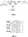
Figure 1 is a schematic diagram of an device in accordance with certain embodiments present invention; -
Figure 2 is a schematic diagram of an accumulator having a two way diaphragm in accordance embodiments of the present invention; -
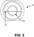
Figure 3 is a top view of a spacer plate in accordance with certain embodiments of the present invention; -
Figure 4 is a cross-sectional view of an accumulator in accordance with certain embodiments of the present invention; and -
Figure 5 is an exploded perspective view of an accumulator in accordance with certain embodiments of the present invention. - As seen in
Figure 1 , the infusion apparatus of the present invention includes a metering assembly having a programmablevalve accumulator pump 30, aninfusate reservoir 10 that can be conventional and well-known in the art, and anexternal programmer 34. Those skilled in the art will appreciate that an external programmer is not necessary; for example, the device could be used in a fixed rate configuration that is never programmed but is preset. Thereservoir 10 is a sealedhousing 14 that containsbellows 16 that includes an internal volume that contains the medicament or other fluid to be infused. The reservoir is preferably rechargeable. External of the bellow is achamber 20 that contains a fluid, such as a two-phase fluid having a significant vapor pressure at normal body pressure so that it compresses the bellows and causes the fluid in the bellows to exit the outlet of thehousing 14. The outlet communicates with the metering assembly, such as via abacterial filter 24, the metering assembly generally comprising anaccumulator 30 and aninlet valve 26 and anoutlet valve 28 in fluid isolation from the inlet valve. Preferably the metering assembly is electronically controlled in accordance with convention. - Turning now to
Figures 4 and5 ,accumulator 30 is shown. Theaccumulator 30 includes ahousing 50, that together withcap 51 defines a sealedgas chamber 52. Thecap 51 is attached to thehousing 50 by any suitable means, such as laser welding. A suitable gas is sealed, under positive pressure, in thegas chamber 52. Thegas chamber 52 is in fluid communication withdiaphragm chamber 57 via aport 55 in thehousing 50. The bottom surface of thehousing 50 is configured and positioned to serve as a mechanical stop for thediaphragm 50 when thediaphragm 50 is in the up (fill) position. - Affixed to the
housing 50 is afaceplate 56. Preferably the edges of thediaphragm 40 are sandwiched between thehousing 50 andfaceplate 57 as shown, and the assembly is sealed, such as by laser welding. The volume between thehousing 50 andfaceplate 57, containing thediaphragm 40, defines thediaphragm chamber 57. Thediaphragm 40 thus provides a barrier, separating the gas side (e.g., above the diaphragm) from the fluid side (e.g., below the diaphragm) in theaccumulator 30. Faceplate 56 also includes afluid inlet port 58 that provides fluid communication betweeninlet valve 26 and thediaphragm chamber 57, andfluid outlet port 59 that provides fluid communication betweenoutlet valve 28 and thediaphragm chamber 57. - Turning now to
Figure 2 , the operation of the accumulator assembly is shown schematically. A normally closedinlet valve 26 is in fluid communication with theinlet port 58 of the accumulator 30 (and the outlet of thereservoir 10 via line 22). A normally closedoutlet valve 28 is in fluid communication with theoutlet port 59 of theaccumulator 30. Miniature solenoid valves are suitable. Preferably thevalves Figure 1 ). The outlet of theaccumulator 30 communicates with a catheter or the like vialine 36 that delivers the infusate to the delivery site in the patient in a conventional manner. - The
diaphragm 40, as illustrated inFIGS. 2 and4 , is a circular disk of a thin metal sheet. Preferably titanium may be used, although other materials also may be suitable as determined by those skilled in the art. The disk is selected to have a diameter and thickness of low spring rate over the desired range of deflection. Thus, the diaphragm acts as a compliant, flexible wall which separates fluid from the environment behind it. The upward and downward motions of thediaphragm 40 are limited by the bottom surface of thehousing 50, and the top surface of thefaceplate 56, each of which serves as a mechanical stop for the diaphragm, depending on whether thediaphragm chamber 57 is filled with infusate or is empty of infusate. Thus, these surfaces are provided with a shallow concave profile manufactured into its diaphragm contact surface. This surface acts as a contour stop for the diaphragm. Dimensions of the contour are chosen to match the general profile of the diaphragm when it is deflected or biased by a predetermined fixed volume. This predetermined fixed volume is the volume desired to be metered from the accumulator (e.g., 2µl). - Deflection of the
diaphragm 40 occurs in both the upward and downward direction. The fixed volume pumped is essentially twice that pumped by a diaphragm of the same size that is only deflected in one direction in the same accumulator package configuration. Thus, the Two Way Diaphragm permits the optimization of accumulator size and energy utilization to increase fixed volume pumping and to conserve battery energy. The first step in theFigure 2 pumping cycle shows theaccumulator 30 in a state where both theinlet valve 26 and theoutlet valve 28 are closed, and thediaphragm chamber 57 of the accumulator is empty (i.e., devoid of infusate fluid). In this condition, preferably thediaphragm 40 is firmly held against thespacer 70 by the gas and is substantially flat; it is not being urged or deflected in either an upward or downward direction (it is noted that the accumulator pressure is generally less than the reservoir pressure and diaphragm spring force and greater than the catheter outlet pressure). The second step in the cycle shows theaccumulator 30 after theinlet valve 26 has been opened (maintaining theoutlet valve 28 closed). The infusate fluid overcomes the bias of the pressurized gas against thediaphragm 40, and deflects thediaphragm 40 upward, thereby filling thediaphragm chamber 57 with fluid from thereservoir 10. The third step in the cycle is the closing of theinlet valve 26 once thediaphragm chamber 57 has been filled to its fixed or desired volume. The fourth step in the cycle is the opening of the outlet valve 28 (while maintaining theinlet valve 26 in the closed position) to empty thediaphragm chamber 57 through thecatheter 36, wherein thediaphragm 40 deflects downward as a result of the bias from the gas pressure in thegas chamber 52 and in the gas side of thediaphragm chamber 57. Accordingly, thediaphragm 40 deflects in a first direction during the filling operation of theaccumulator 30, as infusate fluid under pressure forces the diaphragm upwards against the mechanical stop of the bottom surface of thehousing 50, overcoming the pressure exerted by the gas in the accumulator. The diaphragm also deflects in a second direction during the emptying of theaccumulator 30, past its flat, resting point position, as the pressurized gas in the accumulator forces the diaphragm downward against the mechanical stop of the top surface of thefaceplate 56. The two-way deflection allows twice the volume to be delivered during a single pumping cycle compared to conventional designs, using the substantially same amount of energy. Preferably the first and second directions of deflection of the diaphragm are opposite directions. Theaccumulator 30 thus stores and discharges predetermined volume spikes of infusate at a frequency defined by the cycling rate of the inlet and outlet valves. - Since the metering assembly controls the flow of fluid from the reservoir and does not rely on constant pressure to initiate flow, although a two-phase liquid can be used in the reservoir, a one-phase gas is suitable as well. Suitable gasses include inert gases such as argon, helium and nitrogen, mixtures thereof, and air.
-
FIGS. 5A and 5B of the '887 patent illustrate the details of the spacer plate utilized between the medication accumulation chamber and the accumulator valves. As disclosed in the '887 patent, the continuous contoured surface desirable to use on the gas-filled side of the diaphragm is undesirable on the fluid side. Intimate contact of two relatively flat surfaces with a liquid interface will create flow restrictions when the accumulator is emptied as the plates move toward each other and during filling when the plates move away from each other. This adverse effect was designed to be overcome by the addition of a checkerboard groove pattern as illustrated inFIG. 5B of the '887 patent. Additionally, a circumferential groove was incorporated in the design to establish fluid communication between the inlet and the outlet valves. Objects of the design were to: permit complete free flow of fluid underneath the flattened diaphragm; assist in washing of areas which might otherwise remain stagnant, and; maintain the accumulator dead volume at a minimum level. -
U.S. Patent No. 5,049,141 introduced an improved spacer plate design as illustrated inFigs 5A and 5B of that patent, the purpose of which was to reduce the diaphragm contact area with the plate. It was found that the prior art's use of a checkerboard groove provided too much surface contact area and therefore large molecule drugs could be crushed at the plate and diaphragm contact points resulting in the creation of drug residue. The prior art checkerboard design also created areas where the drug could stagnate and particles and air bubbles could be trapped. The '141 patent introduced an improved spacer plate design utilizing concentric circumferential grooves to establish fluid communication between the inlet and outlet valves and for fluid communication with the trough and a design that would reduce the diaphragm and plate contact area. - The
spacer 70 in accordance with certain embodiments of the present invention improves upon the prior art with a design that maximizes the wash out of fluid and minimizes dead volume. Channels in the spacer are designed to create a flow path that allows the fluid to exit the accumulator quickly (e.g., the channel flow restriction is kept large enough to allow the accumulator to empty in a short period of time). It was found that the multiple annular grooves of the prior art provided multiple sites for stagnant fluid and air encapsulation resulting in dead volume and a degradation of pumping accuracy. As seen inFigures 3 and5 , thespacer 70 of the present invention includes anannular groove 54 intersected by (and thereby in fluid communication with) atrough 53 connecting the inlet and outlet valves wherein the volume of the space created by the annular and trough grooves permits the dead volume in the grooves and outlets to be equal to or less than about 5% of the total volume discharged by the accumulator. Preferably only a singleannular groove 54 is provided, and it is interior to the inlet and outlet apertures respectively communicating with the inlet and outlet valves, such that the diameter of theannular groove 54 is smaller than the length of thetrough 53. Thegroove 54 thus provides an annular flow path, and thetrough 53 provides a lateral flow path between the inlet and outlet of the accumulator. Fluid in thegroove 54 thus communicates with the inlet and outlet of the accumulator only through communication with thetrough 53. The remaining peripheral surface of thespace plate 50 is preferably flat. The new design flow path configuration and placement also allows for the fluid to flow out of the accumulator without adversely affecting the empty time.
Claims (3)
- An implantable infusion apparatus, comprising:an infusate reservoir (10);a metering assembly comprising an accumulator (30) having an inlet (58), an outlet (59), a first mechanical stop (50) and a second mechanical stop (56);an inlet valve (26) in communication with said infusate reservoir and with said accumulator inlet, and an outlet valve in communication with said accumulator outlet;a diaphragm (40) disposed in said accumulator such that said diaphragm has a resting state position, deflects in a first direction in response to the opening of said inlet valve while said outlet valve is closed to cause infusate to flow into said accumulator from said reservoir, and deflects in a second direction in response to the opening of said outlet valve while said inlet valve is closed to cause infusate to flow out of said accumulator outlet, wherein said first direction and said second direction are different: anda gas chamber (52) containing a pressurized gas, wherein said diaphragm provides a barrier between said pressurized gas and any infusate in said accumulator, and said pressurized gas biases said diaphragm in said second direction, where the bias of said diaphragm by said pressurized gas is overcome when said inlet valve is open and said outlet valve is closed; anda valve accumulator pump programmed to selectively actuate said inlet valve to cause infusate to flow into said accumulator and deflect the diaphragm in said first direction and against said first mechanical stop and selectively actuate said outlet valve to cause infusate to flow out of said accumulator and deflect the diaphragm in said second direction and against said second mechanical stop; characterized in that the infusion apparatus further comprises:a spacer (70) having a concave surface defining said second mechanical stop, said concave surface having an annular groove (54) and a trough (53) in fluid communication with said annular groove and with said inlet and said outlet of said accumulator, a diameter of said annular groove being smaller than a length of said trough and smaller than a distance from said inlet to said outlet, said annular groove is the only annular groove in said spacer, and said annular groove and said trough defining a fluid flow path, wherein the volume of said fluid flow path is equal to or less than about 5% of a total volume of infusate discharged by said accumulator.
- The infusion apparatus of claim 1, wherein said reservoir contains a single phase gas.
- The infusion apparatus of claim 1, wherein said infusate flows out of said accumulator in a series of predetermined volume spikes, a frequency of said spikes being determined by a cycling rate of said first valve and said second valve.
Applications Claiming Priority (2)
| Application Number | Priority Date | Filing Date | Title |
|---|---|---|---|
| US11/906,826 US8273058B2 (en) | 2007-10-04 | 2007-10-04 | Two way accumulator programmable valve pump |
| PCT/US2008/010125 WO2009045258A1 (en) | 2007-10-04 | 2008-08-27 | Two way accumulator programmable valve pump |
Publications (3)
| Publication Number | Publication Date |
|---|---|
| EP2193275A1 EP2193275A1 (en) | 2010-06-09 |
| EP2193275A4 EP2193275A4 (en) | 2015-12-09 |
| EP2193275B1 true EP2193275B1 (en) | 2017-11-29 |
Family
ID=40523914
Family Applications (1)
| Application Number | Title | Priority Date | Filing Date |
|---|---|---|---|
| EP08835694.4A Active EP2193275B1 (en) | 2007-10-04 | 2008-08-27 | Two way accumulator programmable valve pump |
Country Status (4)
| Country | Link |
|---|---|
| US (2) | US8273058B2 (en) |
| EP (1) | EP2193275B1 (en) |
| ES (1) | ES2653198T3 (en) |
| WO (1) | WO2009045258A1 (en) |
Families Citing this family (9)
| Publication number | Priority date | Publication date | Assignee | Title |
|---|---|---|---|---|
| US10173004B2 (en) | 2013-01-08 | 2019-01-08 | Flowonix Medical Incorporated | Flow actuated valve for implantable drug delivery device |
| US10533680B2 (en) * | 2013-12-19 | 2020-01-14 | Ge Healthcare Bio-Sciences Ab | Remotely actuated valve for a biological liquid treatment system |
| US20160303318A1 (en) | 2015-04-16 | 2016-10-20 | Flowonix Medical Incorporated | Implantable Drug Delivery Device with Flow Measuring Capabilities |
| US9700669B2 (en) | 2015-04-16 | 2017-07-11 | Flowonix Medical Incorporated | Patient programmer for implantable drug delivery device |
| KR101961415B1 (en) * | 2016-04-27 | 2019-07-17 | 서강대학교산학협력단 | Tubeless implantable drug infusion system |
| KR101839846B1 (en) | 2016-12-09 | 2018-05-04 | 서강대학교산학협력단 | In vivo implantable drug pump driven by external magnetic field |
| KR101905698B1 (en) | 2017-02-17 | 2018-10-08 | 서강대학교 산학협력단 | Implantable drug infusion pump for supporting full-duplex communication and system using the same |
| US10471427B2 (en) | 2017-04-24 | 2019-11-12 | Biorep Technologies, Inc. | Fluidic manifold cartridge system |
| WO2021067674A1 (en) | 2019-10-04 | 2021-04-08 | Flowonix Medical Incorporated | Implantable drug delivery device with infusate measuring capabilities |
Family Cites Families (11)
| Publication number | Priority date | Publication date | Assignee | Title |
|---|---|---|---|---|
| US4431425A (en) * | 1981-04-28 | 1984-02-14 | Quest Medical, Inc. | Flow fault sensing system |
| US5088515A (en) * | 1989-05-01 | 1992-02-18 | Kamen Dean L | Valve system with removable fluid interface |
| US4838887A (en) | 1987-12-15 | 1989-06-13 | Shiley Infusaid Inc. | Programmable valve pump |
| US5049141A (en) * | 1990-04-25 | 1991-09-17 | Infusaid, Inc. | Programmable valve pump |
| US5641892A (en) * | 1995-06-07 | 1997-06-24 | Deka Products Limited Partnership | Intravenous-line air-detection system |
| US5281210A (en) | 1992-09-18 | 1994-01-25 | Infusaid, Inc. | Accumulator for implantable pump |
| IL115327A (en) * | 1994-10-07 | 2000-08-13 | Bayer Ag | Diaphragm pump |
| US6905479B1 (en) * | 1999-07-20 | 2005-06-14 | Deka Products Limited Partnership | Pumping cartridge having an integrated filter and method for filtering a fluid with the cartridge |
| US7896865B2 (en) | 2003-09-30 | 2011-03-01 | Codman & Shurtleff, Inc. | Two-compartment reduced volume infusion pump |
| WO2006123329A2 (en) * | 2005-05-17 | 2006-11-23 | Medingo Ltd. | Disposable dispenser for patient infusion |
| US8034030B2 (en) | 2005-05-25 | 2011-10-11 | Palyon Medical (Bvi) Limited | Multi-reservoir implantable pump with variable flow rate capabilities |
-
2007
- 2007-10-04 US US11/906,826 patent/US8273058B2/en active Active
-
2008
- 2008-08-27 WO PCT/US2008/010125 patent/WO2009045258A1/en active Application Filing
- 2008-08-27 EP EP08835694.4A patent/EP2193275B1/en active Active
- 2008-08-27 ES ES08835694.4T patent/ES2653198T3/en active Active
-
2012
- 2012-09-10 US US13/608,583 patent/US8696627B2/en active Active
Non-Patent Citations (1)
| Title |
|---|
| None * |
Also Published As
| Publication number | Publication date |
|---|---|
| US20130023857A1 (en) | 2013-01-24 |
| WO2009045258A1 (en) | 2009-04-09 |
| US20090093797A1 (en) | 2009-04-09 |
| EP2193275A4 (en) | 2015-12-09 |
| EP2193275A1 (en) | 2010-06-09 |
| US8273058B2 (en) | 2012-09-25 |
| ES2653198T3 (en) | 2018-02-06 |
| US8696627B2 (en) | 2014-04-15 |
Similar Documents
| Publication | Publication Date | Title |
|---|---|---|
| EP2193275B1 (en) | Two way accumulator programmable valve pump | |
| EP0526475B1 (en) | Programmable valve pump | |
| EP2259834B1 (en) | Multiple reservoir implantable drug infusion device and method | |
| EP0488701B1 (en) | Liquid-vapour pressure reservoir for medication infusion pump | |
| EP1888144B1 (en) | Implantable infusion device with multiple controllable fluid outlets | |
| EP0998317B1 (en) | Inlet port for a medication infusion pump | |
| JP2593047B2 (en) | Measuring device for implantable feeding devices | |
| US5281210A (en) | Accumulator for implantable pump | |
| EP1594559B1 (en) | Multi-stage fluid delivery device | |
| US11964129B2 (en) | Implantable continuous-flow pumps | |
| JPH0219172A (en) | Feeder for fluid implanted into organism | |
| WO2023141072A1 (en) | Mems micropump with multi-chamber cavity for a device for delivering insulin |
Legal Events
| Date | Code | Title | Description |
|---|---|---|---|
| PUAI | Public reference made under article 153(3) epc to a published international application that has entered the european phase |
Free format text: ORIGINAL CODE: 0009012 |
|
| 17P | Request for examination filed |
Effective date: 20100312 |
|
| AK | Designated contracting states |
Kind code of ref document: A1 Designated state(s): AT BE BG CH CY CZ DE DK EE ES FI FR GB GR HR HU IE IS IT LI LT LU LV MC MT NL NO PL PT RO SE SI SK TR |
|
| AX | Request for extension of the european patent |
Extension state: AL BA MK RS |
|
| DAX | Request for extension of the european patent (deleted) | ||
| RA4 | Supplementary search report drawn up and despatched (corrected) |
Effective date: 20151109 |
|
| RIC1 | Information provided on ipc code assigned before grant |
Ipc: F04B 43/04 20060101AFI20151103BHEP Ipc: A61M 5/142 20060101ALI20151103BHEP Ipc: A61M 5/148 20060101ALI20151103BHEP Ipc: A61M 5/168 20060101ALI20151103BHEP Ipc: G01F 11/08 20060101ALI20151103BHEP |
|
| GRAP | Despatch of communication of intention to grant a patent |
Free format text: ORIGINAL CODE: EPIDOSNIGR1 |
|
| INTG | Intention to grant announced |
Effective date: 20170809 |
|
| RIN1 | Information on inventor provided before grant (corrected) |
Inventor name: O'CONNOR, PATRICK Inventor name: BURKE, PAUL, F. |
|
| GRAS | Grant fee paid |
Free format text: ORIGINAL CODE: EPIDOSNIGR3 |
|
| RAP1 | Party data changed (applicant data changed or rights of an application transferred) |
Owner name: FLOWONIX MEDICAL INCORPORATED |
|
| GRAA | (expected) grant |
Free format text: ORIGINAL CODE: 0009210 |
|
| AK | Designated contracting states |
Kind code of ref document: B1 Designated state(s): AT BE BG CH CY CZ DE DK EE ES FI FR GB GR HR HU IE IS IT LI LT LU LV MC MT NL NO PL PT RO SE SI SK TR |
|
| REG | Reference to a national code |
Ref country code: GB Ref legal event code: FG4D |
|
| REG | Reference to a national code |
Ref country code: CH Ref legal event code: EP |
|
| REG | Reference to a national code |
Ref country code: AT Ref legal event code: REF Ref document number: 950646 Country of ref document: AT Kind code of ref document: T Effective date: 20171215 |
|
| REG | Reference to a national code |
Ref country code: IE Ref legal event code: FG4D |
|
| REG | Reference to a national code |
Ref country code: DE Ref legal event code: R096 Ref document number: 602008053195 Country of ref document: DE |
|
| REG | Reference to a national code |
Ref country code: ES Ref legal event code: FG2A Ref document number: 2653198 Country of ref document: ES Kind code of ref document: T3 Effective date: 20180206 |
|
| REG | Reference to a national code |
Ref country code: NL Ref legal event code: MP Effective date: 20171129 |
|
| REG | Reference to a national code |
Ref country code: LT Ref legal event code: MG4D |
|
| PG25 | Lapsed in a contracting state [announced via postgrant information from national office to epo] |
Ref country code: FI Free format text: LAPSE BECAUSE OF FAILURE TO SUBMIT A TRANSLATION OF THE DESCRIPTION OR TO PAY THE FEE WITHIN THE PRESCRIBED TIME-LIMIT Effective date: 20171129 Ref country code: LT Free format text: LAPSE BECAUSE OF FAILURE TO SUBMIT A TRANSLATION OF THE DESCRIPTION OR TO PAY THE FEE WITHIN THE PRESCRIBED TIME-LIMIT Effective date: 20171129 Ref country code: NO Free format text: LAPSE BECAUSE OF FAILURE TO SUBMIT A TRANSLATION OF THE DESCRIPTION OR TO PAY THE FEE WITHIN THE PRESCRIBED TIME-LIMIT Effective date: 20180228 Ref country code: SE Free format text: LAPSE BECAUSE OF FAILURE TO SUBMIT A TRANSLATION OF THE DESCRIPTION OR TO PAY THE FEE WITHIN THE PRESCRIBED TIME-LIMIT Effective date: 20171129 |
|
| PG25 | Lapsed in a contracting state [announced via postgrant information from national office to epo] |
Ref country code: HR Free format text: LAPSE BECAUSE OF FAILURE TO SUBMIT A TRANSLATION OF THE DESCRIPTION OR TO PAY THE FEE WITHIN THE PRESCRIBED TIME-LIMIT Effective date: 20171129 Ref country code: GR Free format text: LAPSE BECAUSE OF FAILURE TO SUBMIT A TRANSLATION OF THE DESCRIPTION OR TO PAY THE FEE WITHIN THE PRESCRIBED TIME-LIMIT Effective date: 20180301 Ref country code: LV Free format text: LAPSE BECAUSE OF FAILURE TO SUBMIT A TRANSLATION OF THE DESCRIPTION OR TO PAY THE FEE WITHIN THE PRESCRIBED TIME-LIMIT Effective date: 20171129 Ref country code: BG Free format text: LAPSE BECAUSE OF FAILURE TO SUBMIT A TRANSLATION OF THE DESCRIPTION OR TO PAY THE FEE WITHIN THE PRESCRIBED TIME-LIMIT Effective date: 20180228 |
|
| PG25 | Lapsed in a contracting state [announced via postgrant information from national office to epo] |
Ref country code: NL Free format text: LAPSE BECAUSE OF FAILURE TO SUBMIT A TRANSLATION OF THE DESCRIPTION OR TO PAY THE FEE WITHIN THE PRESCRIBED TIME-LIMIT Effective date: 20171129 |
|
| PG25 | Lapsed in a contracting state [announced via postgrant information from national office to epo] |
Ref country code: SK Free format text: LAPSE BECAUSE OF FAILURE TO SUBMIT A TRANSLATION OF THE DESCRIPTION OR TO PAY THE FEE WITHIN THE PRESCRIBED TIME-LIMIT Effective date: 20171129 Ref country code: CZ Free format text: LAPSE BECAUSE OF FAILURE TO SUBMIT A TRANSLATION OF THE DESCRIPTION OR TO PAY THE FEE WITHIN THE PRESCRIBED TIME-LIMIT Effective date: 20171129 Ref country code: DK Free format text: LAPSE BECAUSE OF FAILURE TO SUBMIT A TRANSLATION OF THE DESCRIPTION OR TO PAY THE FEE WITHIN THE PRESCRIBED TIME-LIMIT Effective date: 20171129 Ref country code: CY Free format text: LAPSE BECAUSE OF FAILURE TO SUBMIT A TRANSLATION OF THE DESCRIPTION OR TO PAY THE FEE WITHIN THE PRESCRIBED TIME-LIMIT Effective date: 20171129 Ref country code: EE Free format text: LAPSE BECAUSE OF FAILURE TO SUBMIT A TRANSLATION OF THE DESCRIPTION OR TO PAY THE FEE WITHIN THE PRESCRIBED TIME-LIMIT Effective date: 20171129 |
|
| REG | Reference to a national code |
Ref country code: DE Ref legal event code: R097 Ref document number: 602008053195 Country of ref document: DE |
|
| PG25 | Lapsed in a contracting state [announced via postgrant information from national office to epo] |
Ref country code: PL Free format text: LAPSE BECAUSE OF FAILURE TO SUBMIT A TRANSLATION OF THE DESCRIPTION OR TO PAY THE FEE WITHIN THE PRESCRIBED TIME-LIMIT Effective date: 20171129 Ref country code: RO Free format text: LAPSE BECAUSE OF FAILURE TO SUBMIT A TRANSLATION OF THE DESCRIPTION OR TO PAY THE FEE WITHIN THE PRESCRIBED TIME-LIMIT Effective date: 20171129 |
|
| PLBE | No opposition filed within time limit |
Free format text: ORIGINAL CODE: 0009261 |
|
| STAA | Information on the status of an ep patent application or granted ep patent |
Free format text: STATUS: NO OPPOSITION FILED WITHIN TIME LIMIT |
|
| 26N | No opposition filed |
Effective date: 20180830 |
|
| PG25 | Lapsed in a contracting state [announced via postgrant information from national office to epo] |
Ref country code: SI Free format text: LAPSE BECAUSE OF FAILURE TO SUBMIT A TRANSLATION OF THE DESCRIPTION OR TO PAY THE FEE WITHIN THE PRESCRIBED TIME-LIMIT Effective date: 20171129 |
|
| PG25 | Lapsed in a contracting state [announced via postgrant information from national office to epo] |
Ref country code: MC Free format text: LAPSE BECAUSE OF FAILURE TO SUBMIT A TRANSLATION OF THE DESCRIPTION OR TO PAY THE FEE WITHIN THE PRESCRIBED TIME-LIMIT Effective date: 20171129 |
|
| REG | Reference to a national code |
Ref country code: CH Ref legal event code: PL |
|
| REG | Reference to a national code |
Ref country code: AT Ref legal event code: UEP Ref document number: 950646 Country of ref document: AT Kind code of ref document: T Effective date: 20171129 |
|
| PG25 | Lapsed in a contracting state [announced via postgrant information from national office to epo] |
Ref country code: CH Free format text: LAPSE BECAUSE OF NON-PAYMENT OF DUE FEES Effective date: 20180831 Ref country code: LI Free format text: LAPSE BECAUSE OF NON-PAYMENT OF DUE FEES Effective date: 20180831 Ref country code: LU Free format text: LAPSE BECAUSE OF NON-PAYMENT OF DUE FEES Effective date: 20180827 |
|
| REG | Reference to a national code |
Ref country code: BE Ref legal event code: MM Effective date: 20180831 |
|
| PG25 | Lapsed in a contracting state [announced via postgrant information from national office to epo] |
Ref country code: FR Free format text: LAPSE BECAUSE OF NON-PAYMENT OF DUE FEES Effective date: 20180831 Ref country code: BE Free format text: LAPSE BECAUSE OF NON-PAYMENT OF DUE FEES Effective date: 20180831 |
|
| PG25 | Lapsed in a contracting state [announced via postgrant information from national office to epo] |
Ref country code: MT Free format text: LAPSE BECAUSE OF NON-PAYMENT OF DUE FEES Effective date: 20180827 |
|
| PG25 | Lapsed in a contracting state [announced via postgrant information from national office to epo] |
Ref country code: TR Free format text: LAPSE BECAUSE OF FAILURE TO SUBMIT A TRANSLATION OF THE DESCRIPTION OR TO PAY THE FEE WITHIN THE PRESCRIBED TIME-LIMIT Effective date: 20171129 |
|
| PG25 | Lapsed in a contracting state [announced via postgrant information from national office to epo] |
Ref country code: PT Free format text: LAPSE BECAUSE OF FAILURE TO SUBMIT A TRANSLATION OF THE DESCRIPTION OR TO PAY THE FEE WITHIN THE PRESCRIBED TIME-LIMIT Effective date: 20171129 Ref country code: HU Free format text: LAPSE BECAUSE OF FAILURE TO SUBMIT A TRANSLATION OF THE DESCRIPTION OR TO PAY THE FEE WITHIN THE PRESCRIBED TIME-LIMIT; INVALID AB INITIO Effective date: 20080827 |
|
| PG25 | Lapsed in a contracting state [announced via postgrant information from national office to epo] |
Ref country code: IE Free format text: LAPSE BECAUSE OF NON-PAYMENT OF DUE FEES Effective date: 20180827 |
|
| PG25 | Lapsed in a contracting state [announced via postgrant information from national office to epo] |
Ref country code: IS Free format text: LAPSE BECAUSE OF FAILURE TO SUBMIT A TRANSLATION OF THE DESCRIPTION OR TO PAY THE FEE WITHIN THE PRESCRIBED TIME-LIMIT Effective date: 20180329 |
|
| PGFP | Annual fee paid to national office [announced via postgrant information from national office to epo] |
Ref country code: IT Payment date: 20230822 Year of fee payment: 16 Ref country code: GB Payment date: 20230828 Year of fee payment: 16 Ref country code: ES Payment date: 20230901 Year of fee payment: 16 Ref country code: AT Payment date: 20230821 Year of fee payment: 16 |
|
| PGFP | Annual fee paid to national office [announced via postgrant information from national office to epo] |
Ref country code: DE Payment date: 20230829 Year of fee payment: 16 |