EP2189887A2 - Terminal and method for using the internet - Google Patents
Terminal and method for using the internet Download PDFInfo
- Publication number
- EP2189887A2 EP2189887A2 EP09156104A EP09156104A EP2189887A2 EP 2189887 A2 EP2189887 A2 EP 2189887A2 EP 09156104 A EP09156104 A EP 09156104A EP 09156104 A EP09156104 A EP 09156104A EP 2189887 A2 EP2189887 A2 EP 2189887A2
- Authority
- EP
- European Patent Office
- Prior art keywords
- key
- touch
- web page
- address
- window
- Prior art date
- Legal status (The legal status is an assumption and is not a legal conclusion. Google has not performed a legal analysis and makes no representation as to the accuracy of the status listed.)
- Granted
Links
Images


Classifications
-
- G—PHYSICS
- G06—COMPUTING; CALCULATING OR COUNTING
- G06F—ELECTRIC DIGITAL DATA PROCESSING
- G06F3/00—Input arrangements for transferring data to be processed into a form capable of being handled by the computer; Output arrangements for transferring data from processing unit to output unit, e.g. interface arrangements
- G06F3/01—Input arrangements or combined input and output arrangements for interaction between user and computer
- G06F3/048—Interaction techniques based on graphical user interfaces [GUI]
- G06F3/0484—Interaction techniques based on graphical user interfaces [GUI] for the control of specific functions or operations, e.g. selecting or manipulating an object, an image or a displayed text element, setting a parameter value or selecting a range
- G06F3/0486—Drag-and-drop
-
- G—PHYSICS
- G06—COMPUTING; CALCULATING OR COUNTING
- G06F—ELECTRIC DIGITAL DATA PROCESSING
- G06F16/00—Information retrieval; Database structures therefor; File system structures therefor
- G06F16/90—Details of database functions independent of the retrieved data types
- G06F16/95—Retrieval from the web
- G06F16/955—Retrieval from the web using information identifiers, e.g. uniform resource locators [URL]
- G06F16/9562—Bookmark management
-
- G—PHYSICS
- G06—COMPUTING; CALCULATING OR COUNTING
- G06F—ELECTRIC DIGITAL DATA PROCESSING
- G06F3/00—Input arrangements for transferring data to be processed into a form capable of being handled by the computer; Output arrangements for transferring data from processing unit to output unit, e.g. interface arrangements
- G06F3/01—Input arrangements or combined input and output arrangements for interaction between user and computer
- G06F3/048—Interaction techniques based on graphical user interfaces [GUI]
- G06F3/0481—Interaction techniques based on graphical user interfaces [GUI] based on specific properties of the displayed interaction object or a metaphor-based environment, e.g. interaction with desktop elements like windows or icons, or assisted by a cursor's changing behaviour or appearance
-
- G—PHYSICS
- G06—COMPUTING; CALCULATING OR COUNTING
- G06F—ELECTRIC DIGITAL DATA PROCESSING
- G06F3/00—Input arrangements for transferring data to be processed into a form capable of being handled by the computer; Output arrangements for transferring data from processing unit to output unit, e.g. interface arrangements
- G06F3/01—Input arrangements or combined input and output arrangements for interaction between user and computer
- G06F3/048—Interaction techniques based on graphical user interfaces [GUI]
- G06F3/0487—Interaction techniques based on graphical user interfaces [GUI] using specific features provided by the input device, e.g. functions controlled by the rotation of a mouse with dual sensing arrangements, or of the nature of the input device, e.g. tap gestures based on pressure sensed by a digitiser
- G06F3/0488—Interaction techniques based on graphical user interfaces [GUI] using specific features provided by the input device, e.g. functions controlled by the rotation of a mouse with dual sensing arrangements, or of the nature of the input device, e.g. tap gestures based on pressure sensed by a digitiser using a touch-screen or digitiser, e.g. input of commands through traced gestures
- G06F3/04883—Interaction techniques based on graphical user interfaces [GUI] using specific features provided by the input device, e.g. functions controlled by the rotation of a mouse with dual sensing arrangements, or of the nature of the input device, e.g. tap gestures based on pressure sensed by a digitiser using a touch-screen or digitiser, e.g. input of commands through traced gestures for inputting data by handwriting, e.g. gesture or text
-
- G—PHYSICS
- G06—COMPUTING; CALCULATING OR COUNTING
- G06F—ELECTRIC DIGITAL DATA PROCESSING
- G06F3/00—Input arrangements for transferring data to be processed into a form capable of being handled by the computer; Output arrangements for transferring data from processing unit to output unit, e.g. interface arrangements
- G06F3/01—Input arrangements or combined input and output arrangements for interaction between user and computer
- G06F3/048—Interaction techniques based on graphical user interfaces [GUI]
- G06F3/0487—Interaction techniques based on graphical user interfaces [GUI] using specific features provided by the input device, e.g. functions controlled by the rotation of a mouse with dual sensing arrangements, or of the nature of the input device, e.g. tap gestures based on pressure sensed by a digitiser
- G06F3/0489—Interaction techniques based on graphical user interfaces [GUI] using specific features provided by the input device, e.g. functions controlled by the rotation of a mouse with dual sensing arrangements, or of the nature of the input device, e.g. tap gestures based on pressure sensed by a digitiser using dedicated keyboard keys or combinations thereof
-
- H—ELECTRICITY
- H04—ELECTRIC COMMUNICATION TECHNIQUE
- H04M—TELEPHONIC COMMUNICATION
- H04M1/00—Substation equipment, e.g. for use by subscribers
- H04M1/72—Mobile telephones; Cordless telephones, i.e. devices for establishing wireless links to base stations without route selection
- H04M1/724—User interfaces specially adapted for cordless or mobile telephones
- H04M1/72403—User interfaces specially adapted for cordless or mobile telephones with means for local support of applications that increase the functionality
- H04M1/72445—User interfaces specially adapted for cordless or mobile telephones with means for local support of applications that increase the functionality for supporting Internet browser applications
-
- H—ELECTRICITY
- H04—ELECTRIC COMMUNICATION TECHNIQUE
- H04M—TELEPHONIC COMMUNICATION
- H04M1/00—Substation equipment, e.g. for use by subscribers
- H04M1/72—Mobile telephones; Cordless telephones, i.e. devices for establishing wireless links to base stations without route selection
- H04M1/724—User interfaces specially adapted for cordless or mobile telephones
- H04M1/72466—User interfaces specially adapted for cordless or mobile telephones with selection means, e.g. keys, having functions defined by the mode or the status of the device
Definitions
- the present disclosure relates to terminal which may assign a short-cut address conveniently while communicating with the Internet.
- terminals can be classified into mobile/portable terminals and stationary terminals.
- the mobile terminals can be classified into handheld terminals and vehicle mount terminals again according to possibility of user's direct portability.
- the terminal As functions of the terminal are diversified, the terminal is implemented as a multimedia player provided with composite functions such as photographing of photos or moving pictures, playback of music or moving picture files, game play, broadcast reception and the like for example.
- a mobile terminal may include a touch screen in the display unit as a method for providing convenient user interface (UI) to user.
- UI user interface
- a user executing wireless Internet access by means of the mobile terminal may want to use a short-cut function in order to quickly move to a desired web page due to Internet fare or fast search.
- an object of the present disclosure is to provide a terminal which may assign a web page address to a short-cut code conveniently during Internet access.
- Another object of the present disclosure is to provide a terminal which may access the web page address by the short-cut code which is assigned to the process.
- a mobile terminal according to the present disclosure is arranged as set out in claim 1.
- mobile terminals described in this disclosure can include a mobile phone, a smart phone, a laptop computer, a digital broadcast terminal, a PDA (personal digital assistants), a PMP (portable multimedia player), a navigation system and the like.
- PDA personal digital assistants
- PMP portable multimedia player
- FIG. 1 is a block diagram of a mobile terminal according to one embodiment of the present disclosure.
- a mobile terminal 100 includes a wireless communication unit 110, an A/V (audio/video) input unit 120, a user input unit 130, a sensing unit 140, an output unit 150, a memory 160, an interface unit 170, a controller 180, a power supply unit 190 and the like.
- FIG. 1 shows the mobile terminal 100 having various components, but it is understood that implementing all of the illustrated components is not a requirement. Greater or fewer components may alternatively be implemented.
- the wireless communication unit 110 typically includes one or more components which permit wireless communication between the mobile terminal 100 and a wireless communication system or network within which the mobile terminal 100 is located.
- the wireless communication unit 110 can include a broadcast receiving module 111, a mobile communication module 112, a wireless Internet module 113, a short-range communication module 114, a position-location module 115 and the like.
- the broadcast receiving module 111 receives a broadcast signal and/or broadcast associated information from an external broadcast managing server via a broadcast channel.
- the broadcast channel may include a satellite channel and a terrestrial channel.
- the broadcast managing server generally refers to a server which generates and transmits a broadcast signal and/or broadcast associated information or a server which is provided with a previously generated broadcast signal and/or broadcast associated information and then transmits the provided signal or information to a terminal.
- the broadcast signal may be implemented as a TV broadcast signal, a radio broadcast signal, and a data broadcast signal, among others. If desired, the broadcast signal may further include a broadcast signal combined with a TV or radio broadcast signal.
- the broadcast associated information includes information associated with a broadcast channel, a broadcast program, a broadcast service provider, etc. And, the broadcast associated information can be provided via a mobile communication network. In this case, the broadcast associated information can be received by the mobile communication module 112.
- broadcast associated information can be implemented in various forms.
- broadcast associated information may include an electronic program guide (EPG) of digital multimedia broadcasting (DMB) and electronic service guide (ESG) of digital video broadcast-handheld (DVB-H).
- EPG electronic program guide
- ESG electronic service guide
- DMB digital multimedia broadcasting
- DVB-H digital video broadcast-handheld
- the broadcast receiving module 111 may be configured to receive broadcast signals transmitted from various types of broadcast systems.
- broadcasting systems include digital multimedia broadcasting-terrestrial (DMB-T), digital multimedia broadcasting-satellite (DMB-S), digital video broadcast-handheld (DVB-H), the data broadcasting system known as media forward link only (MediaFLO®) and integrated services digital broadcast-terrestrial (ISDB-T).
- DMB-T digital multimedia broadcasting-terrestrial
- DMB-S digital multimedia broadcasting-satellite
- DVD-H digital video broadcast-handheld
- MediaFLO® media forward link only
- ISDB-T integrated services digital broadcast-terrestrial
- the broadcast receiving module 111 can be configured suitable for other broadcasting systems as well as the above-explained digital broadcasting systems.
- the broadcast signal and/or broadcast associated information received by the broadcast receiving module 111 may be stored in a suitable device, such as a memory 160.
- the mobile communication module 112 transmits/receives wireless signals to/from one or more network entities (e.g., base station, external terminal, server, etc.). Such wireless signals may represent audio, video, and data according to text/multimedia message transceiving, among others.
- network entities e.g., base station, external terminal, server, etc.
- Such wireless signals may represent audio, video, and data according to text/multimedia message transceiving, among others.
- the wireless Internet module 113 supports Internet access for the mobile terminal 100.
- This module may be internally or externally coupled to the mobile terminal 100.
- the wireless Internet technology can include WLAN(Wireless LAN) (Wi-Fi), Wibro (Wireless broadband), Wimax (World Interoperability for Microwave Access), HSDPA (High Speed Downlink Packet Access), etc.
- the short-range communication module 114 facilitates relatively short-range communications. Suitable technologies for implementing this module include radio frequency identification (RFID), infrared data association (IrDA), ultra-wideband (UWB), as well at the networking technologies commonly referred to as Bluetooth and ZigBee, to name a few.
- RFID radio frequency identification
- IrDA infrared data association
- UWB ultra-wideband
- the position-location module 115 identifies or otherwise obtains the location of the mobile terminal 100. If desired, this module may be implemented with a global positioning system (GPS) module.
- GPS global positioning system
- the audio/video (A/V) input unit 120 is configured to provide audio or video signal input to the mobile terminal 100.
- the A/V input unit 120 includes a camera 121 and a microphone 122.
- the camera 121 receives and processes image frames of still pictures or video, which are obtained by an image sensor in a video call mode or a photographing mode. And, the processed image frames can be displayed on the display 151.
- the image frames processed by the camera 121 can be stored in the memory 160 or can be externally transmitted via the wireless communication unit 110.
- at least two cameras 121 can be provided to the mobile terminal 100 according to environment of usage.
- the microphone 122 receives an external audio signal while the portable device is in a particular mode, such as phone call mode, recording mode and voice recognition. This audio signal is processed and converted into electric audio data. The processed audio data is transformed into a format transmittable to a mobile communication base station via the mobile communication module 112 in case of a call mode.
- the microphone 122 typically includes assorted noise removing algorithms to remove noise generated in the course of receiving the external audio signal.
- the user input unit 130 generates input data responsive to user manipulation of an associated input device or devices.
- Examples of such devices include a keypad, a dome switch, a touchpad (e.g., static pressure/capacitance), a jog wheel, a jog switch, etc.
- the sensing unit 140 provides sensing signals for controlling operations of the mobile terminal 100 using status measurements of various aspects of the mobile terminal. For instance, the sensing unit 140 may detect an open/close status of the mobile terminal 100, relative positioning of components (e.g., a display and keypad) of the mobile terminal 100, a change of position of the mobile terminal 100 or a component of the mobile terminal 100, a presence or absence of user contact with the mobile terminal 100, orientation or acceleration/deceleration of the mobile terminal 100. As an example, consider the mobile terminal 100 being configured as a slide-type mobile terminal. In this configuration, the sensing unit 140 may sense whether a sliding portion of the mobile terminal is open or closed. Other examples include the sensing unit 140 sensing the presence or absence of power provided by the power supply 190, the presence or absence of a coupling or other connection between the interface unit 170 and an external device. And, the sensing unit 140 can include a proximity sensor 141.
- components e.g., a display and keypad
- the output unit 150 generates outputs relevant to the senses of sight, hearing, touch and the like. And, the output unit 150 includes the display 151, an audio output module 152, an alarm unit 153, and a haptic module 154 and the like.
- the display 151 is typically implemented to visually display (output) information associated with the mobile terminal 100. For instance, if the mobile terminal is operating in a phone call mode, the display will generally provide a user interface (UI) or graphical user interface (GUI) which includes information associated with placing, conducting, and terminating a phone call. As another example, if the mobile terminal 100 is in a video call mode or a photographing mode, the display 151 may additionally or alternatively display images which are associated with these modes, the UI or the GUI.
- UI user interface
- GUI graphical user interface
- the display module 151 may be implemented using known display technologies including, for example, a liquid crystal display (LCD), a thin film transistor-liquid crystal display (TFT-LCD), an organic light-emitting diode display (OLED), a flexible display and a three-dimensional display.
- LCD liquid crystal display
- TFT-LCD thin film transistor-liquid crystal display
- OLED organic light-emitting diode display
- the mobile terminal 100 may include one or more of such displays.
- Some of the above displays can be implemented in a transparent or optically transmittive type, which can be named a transparent display.
- a transparent display there is TOLED (transparent OLED) or the like.
- a rear configuration of the display 151 can be implemented in the optically transmittive type as well. In this configuration, a user is able to see an object in rear of a terminal body via the area occupied by the display 151 of the terminal body.
- At least two displays 151 can be provided to the mobile terminal 100 in accordance with the implemented configuration of the mobile terminal 100.
- a plurality of displays can be arranged on a single face of the mobile terminal 100 in a manner of being spaced apart from each other or being built in one body.
- a plurality of displays can be arranged on different faces of the mobile terminal 100.
- the display 151 and a sensor for detecting a touch action configures a mutual layer structure (hereinafter called 'touch screen')
- the touch sensor can be configured as a touch film, a touch sheet, a touchpad or the like.
- the touch sensor can be configured to convert pressure applied to a specific portion of the display 151 or a variation of capacitance generated from a specific portion of the display 151 into an electric input signal. Moreover, it is possible to configure the touch sensor to detect touch pressure as well as a touched position or size.
- a touch input is made to the touch sensor, one or more signals corresponding to the touch is transferred to a touch controller.
- the touch controller processes the signal(s) and then transfers the processed signal(s) to the controller 180. Therefore, the controller 180 is able to know whether a prescribed portion of the display 151 is touched.
- a proximity sensor (not shown in the drawing) can be provided to an internal area of the mobile terminal 100 enclosed by the touch screen or around the touch screen.
- the proximity sensor is the sensor that detects a presence or non-presence of an object approaching a prescribed detecting surface or an object existing around the proximity sensor using an electromagnetic field strength or infrared ray without mechanical contact.
- the proximity sensor has durability longer than that of a contact type sensor and also has utility wider than that of the contact type sensor.
- the proximity sensor can include one of a transmittive photoelectric sensor, a direct reflective photoelectric sensor, a mirror reflective photoelectric sensor, a radio frequency oscillation proximity sensor, an electrostatic capacity proximity sensor, a magnetic proximity sensor, an infrared proximity sensor and the like.
- the touch screen includes the electrostatic capacity proximity sensor, it is configured to detect the proximity of a pointer using a variation of electric field according to the proximity of the pointer. In this case, the touch screen (touch sensor) can be classified as the proximity sensor.
- an action that a pointer approaches without contacting with the touch screen to be recognized as located on the touch screen is named 'proximity touch'.
- an action that a pointer actually touches the touch screen is named 'contact touch'.
- the meaning of the position on the touch screen proximity-touched by the pointer means the position of the pointer which vertically opposes the touch screen when the pointer performs the proximity touch.
- the proximity sensor detects a proximity touch and a proximity touch pattern (e.g., a proximity touch distance, a proximity touch duration, a proximity touch position, a proximity touch shift state, etc.). And, information corresponding to the detected proximity touch action and the detected proximity touch pattern can be output to the touch screen.
- a proximity touch and a proximity touch pattern e.g., a proximity touch distance, a proximity touch duration, a proximity touch position, a proximity touch shift state, etc.
- the audio output module 152 functions in various modes including a call-receiving mode, a call-placing mode, a recording mode, a voice recognition mode, a broadcast reception mode and the like to output audio data which is received from the wireless communication unit 110 or is stored in the memory 160. During operation, the audio output module 152 outputs audio relating to a particular function (e.g., call received, message received, etc.). The audio output module 152 is often implemented using one or more speakers, buzzers, other audio producing devices, and combinations thereof.
- the alarm unit 153 is output a signal for announcing the occurrence of a particular event associated with the mobile terminal 100.
- Typical events include a call received event, a message received event and a touch input received event.
- the alarm unit 153 is able to output a signal for announcing the event occurrence by way of vibration as well as video or audio signal.
- the video or audio signal can be output via the display 151 or the audio output unit 152.
- the display 151 or the audio output module 152 can be regarded as a part of the alarm unit 153.
- the haptic module 154 generates various tactile effects that can be sensed by a user. Vibration is a representative one of the tactile effects generated by the haptic module 154. Strength and pattern of the vibration generated by the haptic module 154 are controllable. For instance, different vibrations can be output in a manner of being synthesized together or can be output in sequence.
- the haptic module 154 is able to generate various tactile effects as well as the vibration. For instance, the haptic module 154 generates the effect attributed to the arrangement of pins vertically moving against a contact skin surface, the effect attributed to the injection/suction power of air though an injection/suction hole, the effect attributed to the skim over a skin surface, the effect attributed to the contact with electrode, the effect attributed to the electrostatic force, the effect attributed to the representation of hold/cold sense using an endothermic or exothermic device and the like.
- the haptic module 154 can be implemented to enable a user to sense the tactile effect through a muscle sense of finger, arm or the like as well as to transfer the tactile effect through a direct contact.
- at least two haptic modules 154 can be provided to the mobile terminal 100 in accordance with the corresponding configuration type of the mobile terminal 100.
- the memory unit 160 is generally used to store various types of data to support the processing, control, and storage requirements of the mobile terminal 100. Examples of such data include program instructions for applications operating on the mobile terminal 100, contact data, phonebook data, messages, audio, still pictures, moving pictures, etc. And, a recent use history or a cumulative use frequency of each data (e.g., use frequency for each phonebook, each message or each multimedia) can be stored in the memory unit 160. Moreover, data for various patterns of vibration and/or sound output in case of a touch input to the touch screen can be stored in the memory unit 160.
- the memory 160 may be implemented using any type or combination of suitable volatile and non-volatile memory or storage devices including hard disk, random access memory (RAM), static random access memory (SRAM), electrically erasable programmable read-only memory (EEPROM), erasable programmable read-only memory (EPROM), programmable read-only memory (PROM), read-only memory (ROM), magnetic memory, flash memory, magnetic or optical disk, multimedia card micro type memory, card-type memory (e.g., SD memory, XD memory, etc.), or other similar memory or data storage device.
- RAM random access memory
- SRAM static random access memory
- EEPROM electrically erasable programmable read-only memory
- EPROM erasable programmable read-only memory
- PROM programmable read-only memory
- ROM read-only memory
- magnetic memory flash memory
- flash memory magnetic or optical disk
- multimedia card micro type memory e.g., SD memory, XD memory, etc.
- multimedia card micro type memory e.g.
- the interface unit 170 is often implemented to couple the mobile terminal 100 with external devices.
- the interface unit 170 receives data from the external devices or is supplied with the power and then transfers the data or power to the respective elements of the mobile terminal 100 or enables data within the mobile terminal 100 to be transferred to the external devices.
- the interface unit 170 may be configured using a wired/wireless headset port, an external charger port, a wired/wireless data port, a memory card port, a port for coupling to a device having an identity module, audio input/output ports, video input/output ports, an earphone port and/or the like.
- the identity module is the chip for storing various kinds of information for authenticating a use authority of the mobile terminal 100 and can include User Identify Module (UIM), Subscriber Identify Module (SIM), Universal Subscriber Identity Module (USIM) and/or the like.
- a device having the identity module (hereinafter called 'identity device') can be manufactured as a smart card. Therefore, the identity device is connectible to the mobile terminal 100 via the corresponding port.
- the interface unit 170 When the mobile terminal 110 is connected to an external cradle, the interface unit 170 becomes a passage for supplying the mobile terminal 100 with power from the cradle or a passage for delivering various command signals input from the cradle by a user to the mobile terminal 100.
- Each of the various command signals input from the cradle or the power can operate as a signal enabling the mobile terminal 100 to recognize that it is correctly loaded in the cradle.
- the controller 180 typically controls the overall operations of the mobile terminal 100. For example, the controller 180 performs the control and processing associated with voice calls, data communications, video calls, etc.
- the controller 180 may include a multimedia module 181 that provides multimedia playback.
- the multimedia module 181 may be configured as part of the controller 180, or implemented as a separate component.
- controller 180 is able to perform a pattern recognizing process for recognizing a writing input and a picture drawing input carried out on the touch screen as characters or images, respectively.
- the power supply unit 190 provides power required by the various components for the mobile terminal 100.
- the power may be internal power, external power, or combinations thereof.
- Various embodiments described herein may be implemented in a computer-readable medium using, for example, computer software, hardware, or some combination thereof.
- the embodiments described herein may be implemented within one or more application specific integrated circuits (ASICs), digital signal processors (DSPs), digital signal processing devices (DSPDs), programmable logic devices (PLDs), field programmable gate arrays (FPGAs), processors, controllers, micro-controllers, microprocessors, other electronic units designed to perform the functions described herein, or a selective combination thereof.
- ASICs application specific integrated circuits
- DSPs digital signal processors
- DSPDs digital signal processing devices
- PLDs programmable logic devices
- FPGAs field programmable gate arrays
- processors controllers, micro-controllers, microprocessors, other electronic units designed to perform the functions described herein, or a selective combination thereof.
- controller 180 may also be implemented by the controller 180.
- the embodiments described herein may be implemented with separate software modules, such as procedures and functions, each of which perform one or more of the functions and operations described herein.
- the software codes can be implemented with a software application written in any suitable programming language and may be stored in memory such as the memory 160, and executed by a controller or processor, such as the controller 180.
- FIG. 2A is a front perspective diagram of a mobile terminal according to one embodiment of the present disclosure.
- the mobile terminal 100 shown in the drawing has a bar type terminal body. Yet, the mobile terminal 100 may be implemented in a variety of different configurations. Examples of such configurations include folder-type, slide-type, rotational-type, swing-type and combinations thereof. For clarity, further disclosure will primarily relate to a bar-type mobile terminal 100. However such teachings apply equally to other types of mobile terminals.
- the mobile terminal 100 includes a case (casing, housing, cover, etc.) configuring an exterior thereof.
- the case can be divided into a front case 101 and a rear case 102.
- Various electric/electronic parts are loaded in a space provided between the front and rear cases 101 and 102.
- at least one middle case can be further provided between the front and rear cases 101 and 102 in addition.
- the cases 101 and 102 are formed by injection molding of synthetic resin or can be formed of metal substance such as stainless steel (STS), titanium (Ti) or the like for example.
- STS stainless steel
- Ti titanium
- a display 151, an audio output unit 152, a camera 121, user input units 130/131 and 132, a microphone 122, an interface 180 and the like can be provided to the terminal body, and more particularly, to the front case 101.
- the display 151 occupies most of a main face of the front case 101.
- the audio output unit 151 and the camera 121 are provided to an area adjacent to one of both end portions of the display 151, while the user input unit 131 and the microphone 122 are provided to another area adjacent to the other end portion of the display 151.
- the user input unit 132 and the interface 170 can be provided to lateral sides of the front and rear cases 101 and 102.
- the input unit 130 is manipulated to receive a command for controlling an operation of the terminal 100. And, the input unit 130 is able to include a plurality of manipulating units 131 and 132.
- the manipulating units 131 and 132 can be named a manipulating portion and may adopt any mechanism of a tactile manner that enables a user to perform a manipulation action by experiencing a tactile feeling.
- Content input by the first or second manipulating unit 131 or 132 can be diversely set. For instance, such a command as start, end, scroll and the like is entered by means of the first manipulating unit 131. And, a command for volume adjustment of sound output from the audio output unit 152, a command for switching to a touch recognizing mode of the display 151 or the like can be entered by means of the second manipulating unit 132.
- FIG. 2B is a perspective diagram of a backside of the terminal shown in FIG. 2A .
- a second camera 121' can be additionally provided to a backside of the terminal body, and more particularly, to the rear case 102.
- the camera 121' has a photographing direction that is substantially opposite to that of camera 121 shown in FIG. 2A and may have pixels differing from those of camera 121.
- camera 121 has low pixels enough to capture and transmit a picture of user's face for a video call, while camera 121' has high pixels for capturing a general subject for photography without transmitting the captured subject.
- each of the cameras 121 and 121' can be installed at the terminal body to be rotated or popped up.
- a flash 123 and a mirror 124 are additionally provided adjacent to the camera 121'.
- the flash 123 projects light toward a subject in case of photographing the subject using the camera 121'.
- the mirror 124 enables the user to view user's face reflected by the mirror 124.
- An additional audio output unit 152' can be provided to the backside of the terminal body.
- the additional audio output unit 152' is able to implement a stereo function together with the former audio output unit 152 shown in FIG. 2A and may be used for implementation of a speakerphone mode in talking over the terminal.
- a broadcast signal receiving antenna 124 can be additionally provided to the lateral side of the terminal body as well as an antenna for communication or the like.
- the antenna 124 constructing a portion of the broadcast receiving module 111 shown in FIG. 1 can be retractably provided to the terminal body.
- a power supply unit 190 for supplying power to the terminal 100 is provided to the terminal body.
- the power supply unit 190 can be configured to be built within the terminal body.
- the power supply unit 190 can be configured to be detachably connected to the terminal body.
- a touchpad 135 for detecting a touch can be additionally provided to the rear case 102.
- the touchpad 135 can be configured in a light transmittive type like the display 151.
- the display 151 is configured to output visual information from its both faces, it is possible to recognize the visual information via the touchpad 135 as well.
- the information output from both of the faces can be entirely controlled by the touchpad 135.
- a display is further provided to the touchpad 135 so that a touch screen can be provided to the rear case 102 as well.
- the touchpad 135 is activated by interconnecting with the display 151 of the front case 101.
- the touchpad 135 can be provided in rear of the display 151 in parallel.
- the touchpad 135 can have a size equal to or smaller than that of the display 151.
- FIG. 3A and FIG. 3B are front-view diagrams of a terminal according to one embodiment of the present disclosure for explaining an operational state thereof.
- Such information can be displayed in characters, numerals, symbols, graphics, icons and the like.
- At least one of the characters, numerals, symbols, graphics and icons are represented as a single predetermined array to be implemented in a keypad formation. And, this keypad formation can be so-called 'soft keys'.
- FIG. 3A shows that a touch applied to a soft key is input through a front face of a terminal body.
- the display 151 is operable through an entire area or by being divided into a plurality of regions. In the latter case, a plurality of the regions can be configured interoperable.
- an output window 151a and an input window 151b are displayed on the display 151.
- a soft key 151 c' representing a digit for inputting a phone number or the like is output to the input window 151 b. If the soft key 151c' is touched, a digit corresponding to the touched soft key is output to the output window 151a. If the first manipulating unit 131 is manipulated, a call connection for the phone number displayed on the output window 151a is attempted.
- FIG. 3B shows that a touch applied to a soft key can be input through the rear face of the terminal body. If FIG. 3A shows a case where the terminal body is vertically arranged (portrait), FIG. 3B shows a case where the terminal body is horizontally arranged (landscape). And, the display 151 can be configured to change the output picture according to the arranged direction of the terminal body.
- FIG. 3B shows a text input mode activated in the terminal.
- An output window 151a' and an input window 151b' are displayed on the display 151.
- a plurality of soft keys 151c' representing at least one of characters, symbols and digits can be arranged in the input window 151b'.
- the soft keys 151c' can be arranged in the QWERTY key formation.
- the touch input via the touchpad 135 is advantageous in that viewing of the soft keys 151c' may not be blocked by a touching finger, as compared to the touch input via the front display 151.
- the display 151 and the touchpad 135 are configured transparent, it is possible to visually check fingers located at the backside of the terminal body. Hence, more correct touch inputs are possible.
- the display 151 or the touchpad 135 can be configured to receive a touch input by scrolling.
- a user scrolls the display 151 or the touchpad 135 to shift a cursor or pointer located at an entity (e.g., icon or the like) displayed on the display 151.
- a path of the shifted finger can be visually displayed on the display 151. This may be useful in editing an image displayed on the display 151.
- one function of the terminal can be executed.
- the above case of the simultaneous touch may correspond to a case that the terminal body is held by a user using a thumb and a first finger (clamping).
- the above function can include activation or deactivation for the display 151 or the touchpad 135.
- the proximity sensor 141 described with reference to FIG. 1 is explained in detail with reference to FIG. 4 as follows.
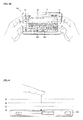
- FIG. 4 is a conceptual diagram for explaining a proximity depth of a proximity sensor.
- a proximity sensor 141 provided within or in the vicinity of the touch screen detects the approach of the pointer and then outputs a proximity signal.
- the proximity sensor 141 can be configured to output a different proximity signal according to a distance between the pointer and the proximity-touched touch screen (hereinafter named 'proximity depth).
- FIG. 4 exemplarily shown is a cross-section of the touch screen provided with a proximity sensor capable to three proximity depths for example. And, it is understood that a proximity sensor capable of proximity depths amounting to the number smaller than 3 or equal to or greater than 4 is possible.
- a contact touch is recognized.
- a proximity touch to a first proximity depth is recognized.
- a proximity touch to a second proximity depth is recognized.
- a proximity touch to a third proximity depth is recognized.
- a proximity touch to a third proximity depth is recognized.
- the controller 180 is able to recognize the proximity touch as one of various input signals according to the proximity depth and position of the pointer. And, the controller 180 is able to perform various operation controls according to the various input signals.
- FIG. 5 is a conceptual diagram for exemplifying a method of controlling a touch action in a state that a pair of displays 156 and 157 overlap each other.
- a folder type terminal in which a folder part is connected to a main body so that it can be folded or unfolded.
- a first display 156 provided in the folder part is a light-transmittive or transparent type such as TOLED, while a second display 157 provided in the main body may be a non-transmittive type such as LCD.
- Each of the first and second displays 156 and 157 can include a touch-inputtable touch screen.
- the controller 180 selects or runs at least one image from an image list displayed on the TOLED 156 depending on the touch type and/or touch duration.
- the TOLED 156 is configured to overlap the LCD 157.
- a touch different from a touch for controlling an image displayed on the TOLED 156 e.g., a long touch (e.g., a touch having a duration of at least 2 seconds) is detected, the controller 180 enables at least one image to be selected from an image list displayed on the LCD 157 depending on the touch input. The result from running the selected image is displayed on the TOLED 156.
- the long touch is usable in selectively shifting a specific one of entities displayed on the LCD 157 to the TOLED 156 (without an action for running the corresponding entity).
- the controller 180 controls the corresponding entity to be displayed by being shifted to the TOLED 156.
- an entity displayed on the TOLED 156 can be displayed by being shifted to the LCD 157 according to such a prescribed touch input to the TOLED 156 as flicking, swirling and the like.
- a second menu displayed on the LCD 157 is displayed by being shifted to the TOLED 156.
- the controller 180 executes a function associated with an image selected by the long touch so that a preview picture for the image can be displayed on the TOLED 156 for example.
- a preview picture for the image can be displayed on the TOLED 156 for example.
- a preview picture of a male
- a second menu image file
- the controller 180 shifts a selection cursor (or a selection bar) of the LCD 157 and then displays the image selected by the selection cursor on the preview picture (picture of female). Thereafter, after completion of the touch (long touch and drag), the controller 180 displays the initial image selected by the long touch.
- the touch action (long touch and drag) is identically applied to a case where a slide (action of a proximity touch corresponding to the drag) is detected together with a long proximity touch (e.g., a proximity touch maintained for at least 2 or 3 seconds) to the TOLED 156.
- a slide action of a proximity touch corresponding to the drag
- a long proximity touch e.g., a proximity touch maintained for at least 2 or 3 seconds
- the controller 180 is able to operate in the same manner of the general touch controlling method.
- the method of controlling the touch action in the overlapped state is applicable to a terminal having a single display. And, the method of controlling the touch action in the overlapped state is applicable to terminals differing from the folder type terminal having a dual display as well.
- FIG. 6A and FIG. 6B are diagrams for the description of a proximity touch recognition area and a tactile effect generation region.
- FIG. 6A represents such an object as an icon, a menu item and the like in a circle type for clarity and convenience of explanation.
- a region for displaying an object on the display 151 can be divided into a first central region A and a second region B surrounding the first region A.
- the first and second regions A and B can be configured to generate tactile effects differing from each other in strength or pattern.
- the first and second regions can be configured to generate 2-step vibrations in a manner of outputting a first vibration if the second region B is touched or outputting a second vibration greater than the first vibration if the first region A is touched.
- both of the proximity touch recognition region and the haptic region are simultaneously set in the region having the object displayed therein, it is possible to set the haptic region for generating the tactile effect to be different from the proximity touch recognition region for detecting the proximity signal.
- the size of the proximity touch recognition region of the display 151 is configured to vary according to the proximity depth.
- the proximity touch recognition region is configured to decrease by C ⁇ B ⁇ A according to the proximity depth for the display 151.
- the proximity touch recognition region is configured to increase by C ⁇ B ⁇ A according to the proximity depth for the display 151.
- it is possible to set the haptic region to have a predetermined size, as the region 'H' shown in (b) of FIG. 6B , regardless of the proximity depth for the display 151.
- the display of the mobile terminal related to an embodiment of the present disclosure may include an address input window showing an address of the accessed Internet web page, and a touch screen having a virtual key pad.
- the controller 180 in the mobile terminal executes an action generating a duplicated window containing a replica of the contents of the address window when the contents are touched and dragged.
- the controller 180 can then respond to a dragging motion by moving the duplicated window accordingly.
- the controller 180 stores a web page address contained the address input window when a dropping action following the dragging motion takes place in a key area of the virtual key pad.
- the controller 180 can then assign the address to a short cut code associated with the key.
- the controller may control the display of the virtual key pad to visually distinguish the keys associated with short-cut codes to which web page addresses are assigned from the other keys having no associated short-cut code. For example, the boundary of the keys having associated short-cut codes may be displayed thicker than others.
- the controller 180 may cause the display of a web page address when a user makes a proximity touch on a key of the virtual key pad associated with a short-cut code to which the web page address is assigned. For instance, an assigned address may be displayed in a bubble window.
- the controller 180 may display a web page address assigned to a key when a touch (contact touch) is made on such key of the virtual key pad.
- the controller 180 may access a web page address assigned to a short cut code associated with a key when a (contact) touch is made on the key of the virtual key pad and maintained for a predetermined time.
- a method of using the Internet may be divided into a method for assigning a web page address to a short cut code which may be associated with a key, and a method for accessing the web page by using the such a key having an associated short cut.
- the subject is typically a mobile terminal. Practically, the controller installed in the mobile terminal executes this method.
- the method for assigning the web page address to a short cut code may comprise: a) detecting a drag and drop motion relative to contents of an address input window; b) determining a key of a virtual key pad having a position where the drag and drop motion is ended; and c) storing an address contained in the address input window and assigning the address to a short cut code which is associated with the key.
- the step a) may comprise detecting a touch in an area where the address input window contents are written, detecting a dragging motion of the touched point which is maintained in touch, and moving a duplicated window according to the motion of the touched point in response to the dragging motion, the duplicated window containing a replica of the web page address written in the address input window.
- the method for assigning the web page address to a short cut code may further comprise displaying a window informing that a web page address is assigned to a short cut code being associated with the key.
- FIG. 7A and FIG.7B an embodiment which is a method for assigning a web page address to a short cut code will be explained referring to FIG. 7A and FIG.7B .
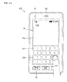
- FIG. 7A is a diagram of an image on the screen of the mobile terminal for displaying a web page according to an embodiment of the present disclosure. As shown in FIG 7A , an address input window where the accessed web page address is written, is positioned at the top portion of the screen.
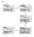
- FIG. 7B is a diagram of an image on the screen of the mobile terminal for illustrating steps of assigning a short-cut code to the web page in an embodiment of the present disclosure from the image of FIG. 7A .
- the controller When a user touches an area S1 where the address of the accessed web page is written in the address input window, as shown a first image view of FIG. 7B , the controller causes a virtual key pad to be displayed in the bottom part of the screen.
- the user may drag the second window where the present web page address is duplicated to the location of a key K1 of the virtual key pad which is placed at the bottom part of the screen, and then drop it at that location.
- This process shown in the first to third image view of FIG. 7B corresponds to step a) in the method for assigning the web page address to the short cut code.
- a message window is displayed, wherein the message window informs that the address is assigned to a short cut code associated with the key ('n' in FIG. 7B ).
- the key is displayed with boundaries thicker than other keys in order to show that the key has a short cut code associated therewith.
- a first method for accessing the web page by using a key having an associated short cut code may comprise: g) receiving a touch in the area of a key on the virtual key pad by a pointing device; h) displaying a web page address assigned to a short cut code associated with the touched key in the address input window; and i) accessing the web page having the displayed web address, when no signal exists in predetermined period (preferably, 0,5 second to 2 second), or if a key indicating a progress (such as the 'enter' key) is input.
- the method may further comprise, before step g), receiving a proximity touch in the area of a key on the virtual key pad by a pointing device and displaying a web page address assigned to a short cut code associated with the key receiving the proximity touch.
- FIG. 8A and FIG. 8B an embodiment which is a first method for accessing the web page by using a key having an associated short cut code will be explained referring to FIG. 8A and FIG. 8B .
- FIG. 8A is a diagram of an image on the screen of the mobile terminal for illustrating steps of an embodiment for accessing a web page using a short-cut code assigned by as explained with reference to FIG. 7B .
- the virtual key pad In the bottom portion of the first image view, the virtual key pad is overlaid.
- the key pad When browsing web page, the key pad is typically not overlaid. It is convenient if the virtual key pad comes to be displayed when it is available for the user to input the address in the address input window by means of touching the address input window during the web browsing.
- the web page address assigned to the short cut code associated with the proximately touched key is displayed in the bubble window (S7).
- the mobile terminal in the third image view, has executed steps g) and h), where step g) is a step of receiving a touch in the area of a key on the virtual key pad by a pointing device, and step h) is a step of displaying a web page address assigned to a short cut code associated with the touched key in the address input window.
- the browsing screen is kept except that the contents of the address input window is changed.
- FIG. 8A in order to add the visual and aesthetic effect, an animation of the bubble window where the changed web page address is written is generated to move to the address input window.
- step i) is executed, i.e. a step of accessing the web page where the contents is changed to be written in the address input window (S6).
- the mobile terminal determines that it is a direct address input process from the address input window S6 as in the prior art. Then, as shown in the FIG. 8B , the input keys ('nt' in FIG. 8B ) are written in the address input window continuously.
- the method for accessing the web page using a key having an associated short cut code may comprise 1) receiving a touch in the area of a key on a virtual key pad by a pointing device for predetermined time, and m) accessing a web page having a web page address assigned to a short cut code associated with the touched key.
- the method may further comprise, before the step 1), displaying a web page address assigned to a short cut code associated with a key when a pointing device touches or makes a proximity touch on the key on the virtual key pad.
- the method may further comprise displaying a character representing the touched key in the address input window before step 1).
- Step 1) then comprises displaying a web page address assigned to a short cut code associated with the touched key in the address input window when the predetermined time has elapsed with the touch maintained.
- FIG. 9 shows diagrams of an image on the screen of mobile terminal for showing the method of accessing the web page using a short cut code which assigned as explained with reference to FIG. 7B .
- some keys K1', K2' in the virtual key pad have associated short cut codes assigned to web page addresses.
- the virtual key pad is overlaid. It is normal that the virtual key pad is not displayed while the web page browsing is executed. During the web page browsing, when the user touches the address input window S6' so that the address input window comes to be a state in which an address may be written, the controller 180 causes the virtual key pad to be overlaid.
- the keys associated with short cut codes are displayed with thicker boundaries in order to be readily identified.
- the user touches one of the keys K1', K2 associated with short cut codes.
- the web page address assigned to the short cut code is then displayed in the bubble window S7' near the touched key K1'.
- the address input window S6' similar to the case of FIG. 8A , may be changed to display the web page address which is assigned to the short cut code.
- the contents of the address input window is changed to the web page address which is assigned to the short cut code associated with the key on which the touch is maintained. Then, the mobile terminal accesses the web page having the changed web address to display a new browsing screen.
- step 1) is a step of receiving a touch in the area of a key on the virtual key pad by a pointing device for predetermined time
- step m) is a step of accessing a web page having a web page address assigned to a short cut code associated with the touched key.
- the controller 180 of the mobile terminal determines that it is a direct input process from the address input window as in the prior art. The input keys are then written in the address input window continuously.
- the aforementioned method may be realized in the form of a storage medium where a program is stored as readable code by a processor embodying the controller 180.
- the readable storage medium may be a ROM, a RAM, a CD-ROM, a magnetic tape, a floppy disk, an optical data storage device and so on.
- the carrier wave (for example, the transmission through the Internet) is available for readable storage medium.
- the mobile terminal having short cut codes for moving the web page is not limited to the constitution and method of the embodiments depicted above. It should be understood that the person in the art may easily modify and alter the present disclosure by combining selectively the entire or part of different embodiments.
Abstract
Description
- The present disclosure relates to terminal which may assign a short-cut address conveniently while communicating with the Internet.
- Generally, terminals can be classified into mobile/portable terminals and stationary terminals. The mobile terminals can be classified into handheld terminals and vehicle mount terminals again according to possibility of user's direct portability.
- As functions of the terminal are diversified, the terminal is implemented as a multimedia player provided with composite functions such as photographing of photos or moving pictures, playback of music or moving picture files, game play, broadcast reception and the like for example.
- To support an increase of the terminal functions, it is possible to consider improving the structural part and/or software part of the terminal.
- A mobile terminal may include a touch screen in the display unit as a method for providing convenient user interface (UI) to user.
- A user executing wireless Internet access by means of the mobile terminal may want to use a short-cut function in order to quickly move to a desired web page due to Internet fare or fast search.
- Accordingly, an object of the present disclosure is to provide a terminal which may assign a web page address to a short-cut code conveniently during Internet access.
- Another object of the present disclosure is to provide a terminal which may access the web page address by the short-cut code which is assigned to the process.
- Additional advantages, objects, and features of the disclosure will be set forth in part in the description which follows and in part will become apparent to those having ordinary skill in the art upon examination of the following or may be learned from practice of the disclosure. The objectives and other advantages of the disclosure may be realized and attained by the structure particularly pointed out in the written description and claims hereof as well as the appended drawings.
- To achieve these objects and other advantages and in accordance with the purpose of the disclosure, as embodied and broadly described herein, a mobile terminal according to the present disclosure is arranged as set out in
claim 1. - In another aspect of the present disclosure, a method for using the Internet as set out in
claim 6 is provided. - It is to be understood that both the foregoing general description and the following detailed description of the present disclosure are exemplary and explanatory and are intended to provide further explanation of the disclosure as claimed.
- The accompanying drawings, which are included to provide a further understanding of the disclosure and are incorporated in and constitute a part of this application, illustrate embodiment(s) of the disclosure and together with the description serve to explain the principle of the disclosure. In the drawings:
-
FIG. 1 is a block diagram of a mobile terminal according to an embodiment of the present disclosure; -
FIG. 2A is a front perspective diagrams of a mobile terminal according to an embodiment of the present disclosure; -
FIG. 2B is a rear perspective diagram of a mobile terminal according to one embodiment of the present disclosure; -
FIG. 3A andFIG. 3B are front diagrams of a mobile terminal according to an embodiment of the present disclosure for explaining operational states of the mobile terminal; -
FIG. 4 is a diagram to explain the concept of proximity depth of a proximity sensor; -
FIG. 5 is a diagram to explain the concept of a method of controlling a touch action on a pair of displays overlapped with each other; -
FIG. 6A and FIG. 6B are diagrams to explain the concepts of a proximity touch recognizing area for detecting a proximity signal and a haptic area for generating a tactile effect, respectively; -
FIG. 7A is a diagram of an image on the screen of the mobile terminal for displaying a web page according to an embodiment of the present disclosure. -
FIG. 7B are diagrams of an image on the screen of the mobile terminal for displaying steps of assigning a short-cut code to the web-page related to an embodiment of the present disclosure from image ofFIG. 7A . -
FIG. 8A are diagrams of an image on the screen of the mobile terminal for displaying steps of an embodiment accessing the web-page using the short-cut code assigned to the step ofFIG. 7B . -
FIG. 8B is a diagram of an image on the screen of the mobile terminal for showing to return the address input state of prior art in case of a continuous key input during the steps ofFIG. 8A . -
FIG. 9 are diagrams of an image on the screen of mobile terminal for showing the step of accessing the web page using the short cut code which is assigned to step shown inFIG. 7B . - Reference will now be made in detail to the preferred embodiments of the present disclosure, examples of which are illustrated in the accompanying drawings. Wherever possible, the same reference numbers will be used throughout the drawings to refer to the same or like parts. The suffixes 'module' and 'unit' for the elements used in the following description are given or used in common by considering facilitation in writing this disclosure only but fail to have meanings or roles discriminated from each other.
- First of all, mobile terminals described in this disclosure can include a mobile phone, a smart phone, a laptop computer, a digital broadcast terminal, a PDA (personal digital assistants), a PMP (portable multimedia player), a navigation system and the like.
- Except where applicable to mobile terminals only, it is apparent to those skilled in the art that the configurations according to an embodiment described in this disclosure are applicable to stationary terminals such as a digital TV, a desktop computer and the like.
-
FIG. 1 is a block diagram of a mobile terminal according to one embodiment of the present disclosure. - Referring to
FIG. 1 , amobile terminal 100 according to an embodiment of the present disclosure includes awireless communication unit 110, an A/V (audio/video)input unit 120, auser input unit 130, asensing unit 140, anoutput unit 150, amemory 160, aninterface unit 170, acontroller 180, apower supply unit 190 and the like.FIG. 1 shows themobile terminal 100 having various components, but it is understood that implementing all of the illustrated components is not a requirement. Greater or fewer components may alternatively be implemented. - In the following description, the above elements of the
mobile terminal 100 are explained in sequence. - First of all, the
wireless communication unit 110 typically includes one or more components which permit wireless communication between themobile terminal 100 and a wireless communication system or network within which themobile terminal 100 is located. For instance, thewireless communication unit 110 can include abroadcast receiving module 111, amobile communication module 112, awireless Internet module 113, a short-range communication module 114, a position-location module 115 and the like. - The
broadcast receiving module 111 receives a broadcast signal and/or broadcast associated information from an external broadcast managing server via a broadcast channel. - The broadcast channel may include a satellite channel and a terrestrial channel.
- The broadcast managing server generally refers to a server which generates and transmits a broadcast signal and/or broadcast associated information or a server which is provided with a previously generated broadcast signal and/or broadcast associated information and then transmits the provided signal or information to a terminal. The broadcast signal may be implemented as a TV broadcast signal, a radio broadcast signal, and a data broadcast signal, among others. If desired, the broadcast signal may further include a broadcast signal combined with a TV or radio broadcast signal.
- The broadcast associated information includes information associated with a broadcast channel, a broadcast program, a broadcast service provider, etc. And, the broadcast associated information can be provided via a mobile communication network. In this case, the broadcast associated information can be received by the
mobile communication module 112. - The broadcast associated information can be implemented in various forms. For instance, broadcast associated information may include an electronic program guide (EPG) of digital multimedia broadcasting (DMB) and electronic service guide (ESG) of digital video broadcast-handheld (DVB-H).
- The
broadcast receiving module 111 may be configured to receive broadcast signals transmitted from various types of broadcast systems. By non-limiting example, such broadcasting systems include digital multimedia broadcasting-terrestrial (DMB-T), digital multimedia broadcasting-satellite (DMB-S), digital video broadcast-handheld (DVB-H), the data broadcasting system known as media forward link only (MediaFLO®) and integrated services digital broadcast-terrestrial (ISDB-T). Optionally, thebroadcast receiving module 111 can be configured suitable for other broadcasting systems as well as the above-explained digital broadcasting systems. - The broadcast signal and/or broadcast associated information received by the
broadcast receiving module 111 may be stored in a suitable device, such as amemory 160. - The
mobile communication module 112 transmits/receives wireless signals to/from one or more network entities (e.g., base station, external terminal, server, etc.). Such wireless signals may represent audio, video, and data according to text/multimedia message transceiving, among others. - The
wireless Internet module 113 supports Internet access for themobile terminal 100. This module may be internally or externally coupled to themobile terminal 100. In this case, the wireless Internet technology can include WLAN(Wireless LAN) (Wi-Fi), Wibro (Wireless broadband), Wimax (World Interoperability for Microwave Access), HSDPA (High Speed Downlink Packet Access), etc. - The short-
range communication module 114 facilitates relatively short-range communications. Suitable technologies for implementing this module include radio frequency identification (RFID), infrared data association (IrDA), ultra-wideband (UWB), as well at the networking technologies commonly referred to as Bluetooth and ZigBee, to name a few. - The position-
location module 115 identifies or otherwise obtains the location of themobile terminal 100. If desired, this module may be implemented with a global positioning system (GPS) module. - Referring to
FIG. 1 , the audio/video (A/V)input unit 120 is configured to provide audio or video signal input to themobile terminal 100. As shown, the A/V input unit 120 includes acamera 121 and amicrophone 122. Thecamera 121 receives and processes image frames of still pictures or video, which are obtained by an image sensor in a video call mode or a photographing mode. And, the processed image frames can be displayed on thedisplay 151. - The image frames processed by the
camera 121 can be stored in thememory 160 or can be externally transmitted via thewireless communication unit 110. Optionally, at least twocameras 121 can be provided to themobile terminal 100 according to environment of usage. - The
microphone 122 receives an external audio signal while the portable device is in a particular mode, such as phone call mode, recording mode and voice recognition. This audio signal is processed and converted into electric audio data. The processed audio data is transformed into a format transmittable to a mobile communication base station via themobile communication module 112 in case of a call mode. Themicrophone 122 typically includes assorted noise removing algorithms to remove noise generated in the course of receiving the external audio signal. - The
user input unit 130 generates input data responsive to user manipulation of an associated input device or devices. Examples of such devices include a keypad, a dome switch, a touchpad (e.g., static pressure/capacitance), a jog wheel, a jog switch, etc. - The
sensing unit 140 provides sensing signals for controlling operations of themobile terminal 100 using status measurements of various aspects of the mobile terminal. For instance, thesensing unit 140 may detect an open/close status of themobile terminal 100, relative positioning of components (e.g., a display and keypad) of themobile terminal 100, a change of position of themobile terminal 100 or a component of themobile terminal 100, a presence or absence of user contact with themobile terminal 100, orientation or acceleration/deceleration of themobile terminal 100. As an example, consider themobile terminal 100 being configured as a slide-type mobile terminal. In this configuration, thesensing unit 140 may sense whether a sliding portion of the mobile terminal is open or closed. Other examples include thesensing unit 140 sensing the presence or absence of power provided by thepower supply 190, the presence or absence of a coupling or other connection between theinterface unit 170 and an external device. And, thesensing unit 140 can include aproximity sensor 141. - The
output unit 150 generates outputs relevant to the senses of sight, hearing, touch and the like. And, theoutput unit 150 includes thedisplay 151, anaudio output module 152, analarm unit 153, and ahaptic module 154 and the like. - The
display 151 is typically implemented to visually display (output) information associated with themobile terminal 100. For instance, if the mobile terminal is operating in a phone call mode, the display will generally provide a user interface (UI) or graphical user interface (GUI) which includes information associated with placing, conducting, and terminating a phone call. As another example, if themobile terminal 100 is in a video call mode or a photographing mode, thedisplay 151 may additionally or alternatively display images which are associated with these modes, the UI or the GUI. - The
display module 151 may be implemented using known display technologies including, for example, a liquid crystal display (LCD), a thin film transistor-liquid crystal display (TFT-LCD), an organic light-emitting diode display (OLED), a flexible display and a three-dimensional display. Themobile terminal 100 may include one or more of such displays. - Some of the above displays can be implemented in a transparent or optically transmittive type, which can be named a transparent display. As a representative example for the transparent display, there is TOLED (transparent OLED) or the like. A rear configuration of the
display 151 can be implemented in the optically transmittive type as well. In this configuration, a user is able to see an object in rear of a terminal body via the area occupied by thedisplay 151 of the terminal body. - At least two
displays 151 can be provided to themobile terminal 100 in accordance with the implemented configuration of themobile terminal 100. For instance, a plurality of displays can be arranged on a single face of themobile terminal 100 in a manner of being spaced apart from each other or being built in one body. Alternatively, a plurality of displays can be arranged on different faces of themobile terminal 100. - In case that the
display 151 and a sensor for detecting a touch action (hereinafter called 'touch sensor') configures a mutual layer structure (hereinafter called 'touch screen'), it is possible to use thedisplay 151 as an input device as well as an output device. In this case, the touch sensor can be configured as a touch film, a touch sheet, a touchpad or the like. - The touch sensor can be configured to convert pressure applied to a specific portion of the
display 151 or a variation of capacitance generated from a specific portion of thedisplay 151 into an electric input signal. Moreover, it is possible to configure the touch sensor to detect touch pressure as well as a touched position or size. - If a touch input is made to the touch sensor, one or more signals corresponding to the touch is transferred to a touch controller. The touch controller processes the signal(s) and then transfers the processed signal(s) to the
controller 180. Therefore, thecontroller 180 is able to know whether a prescribed portion of thedisplay 151 is touched. - Referring to
FIG. 1 , a proximity sensor (not shown in the drawing) can be provided to an internal area of themobile terminal 100 enclosed by the touch screen or around the touch screen. The proximity sensor is the sensor that detects a presence or non-presence of an object approaching a prescribed detecting surface or an object existing around the proximity sensor using an electromagnetic field strength or infrared ray without mechanical contact. Hence, the proximity sensor has durability longer than that of a contact type sensor and also has utility wider than that of the contact type sensor. - The proximity sensor can include one of a transmittive photoelectric sensor, a direct reflective photoelectric sensor, a mirror reflective photoelectric sensor, a radio frequency oscillation proximity sensor, an electrostatic capacity proximity sensor, a magnetic proximity sensor, an infrared proximity sensor and the like. In case that the touch screen includes the electrostatic capacity proximity sensor, it is configured to detect the proximity of a pointer using a variation of electric field according to the proximity of the pointer. In this case, the touch screen (touch sensor) can be classified as the proximity sensor.
- In the following description, for clarity, an action that a pointer approaches without contacting with the touch screen to be recognized as located on the touch screen is named 'proximity touch'. And, an action that a pointer actually touches the touch screen is named 'contact touch'. The meaning of the position on the touch screen proximity-touched by the pointer means the position of the pointer which vertically opposes the touch screen when the pointer performs the proximity touch.
- The proximity sensor detects a proximity touch and a proximity touch pattern (e.g., a proximity touch distance, a proximity touch duration, a proximity touch position, a proximity touch shift state, etc.). And, information corresponding to the detected proximity touch action and the detected proximity touch pattern can be output to the touch screen.
- The
audio output module 152 functions in various modes including a call-receiving mode, a call-placing mode, a recording mode, a voice recognition mode, a broadcast reception mode and the like to output audio data which is received from thewireless communication unit 110 or is stored in thememory 160. During operation, theaudio output module 152 outputs audio relating to a particular function (e.g., call received, message received, etc.). Theaudio output module 152 is often implemented using one or more speakers, buzzers, other audio producing devices, and combinations thereof. - The
alarm unit 153 is output a signal for announcing the occurrence of a particular event associated with themobile terminal 100. Typical events include a call received event, a message received event and a touch input received event. Thealarm unit 153 is able to output a signal for announcing the event occurrence by way of vibration as well as video or audio signal. The video or audio signal can be output via thedisplay 151 or theaudio output unit 152. Hence, thedisplay 151 or theaudio output module 152 can be regarded as a part of thealarm unit 153. - The
haptic module 154 generates various tactile effects that can be sensed by a user. Vibration is a representative one of the tactile effects generated by thehaptic module 154. Strength and pattern of the vibration generated by thehaptic module 154 are controllable. For instance, different vibrations can be output in a manner of being synthesized together or can be output in sequence. - The
haptic module 154 is able to generate various tactile effects as well as the vibration. For instance, thehaptic module 154 generates the effect attributed to the arrangement of pins vertically moving against a contact skin surface, the effect attributed to the injection/suction power of air though an injection/suction hole, the effect attributed to the skim over a skin surface, the effect attributed to the contact with electrode, the effect attributed to the electrostatic force, the effect attributed to the representation of hold/cold sense using an endothermic or exothermic device and the like. - The
haptic module 154 can be implemented to enable a user to sense the tactile effect through a muscle sense of finger, arm or the like as well as to transfer the tactile effect through a direct contact. Optionally, at least twohaptic modules 154 can be provided to themobile terminal 100 in accordance with the corresponding configuration type of themobile terminal 100. - The
memory unit 160 is generally used to store various types of data to support the processing, control, and storage requirements of themobile terminal 100. Examples of such data include program instructions for applications operating on themobile terminal 100, contact data, phonebook data, messages, audio, still pictures, moving pictures, etc. And, a recent use history or a cumulative use frequency of each data (e.g., use frequency for each phonebook, each message or each multimedia) can be stored in thememory unit 160. Moreover, data for various patterns of vibration and/or sound output in case of a touch input to the touch screen can be stored in thememory unit 160. - The
memory 160 may be implemented using any type or combination of suitable volatile and non-volatile memory or storage devices including hard disk, random access memory (RAM), static random access memory (SRAM), electrically erasable programmable read-only memory (EEPROM), erasable programmable read-only memory (EPROM), programmable read-only memory (PROM), read-only memory (ROM), magnetic memory, flash memory, magnetic or optical disk, multimedia card micro type memory, card-type memory (e.g., SD memory, XD memory, etc.), or other similar memory or data storage device. And, themobile terminal 100 is able to operate in association with a web storage for performing a storage function of thememory 160 on Internet. - The
interface unit 170 is often implemented to couple themobile terminal 100 with external devices. Theinterface unit 170 receives data from the external devices or is supplied with the power and then transfers the data or power to the respective elements of themobile terminal 100 or enables data within themobile terminal 100 to be transferred to the external devices. Theinterface unit 170 may be configured using a wired/wireless headset port, an external charger port, a wired/wireless data port, a memory card port, a port for coupling to a device having an identity module, audio input/output ports, video input/output ports, an earphone port and/or the like. - The identity module is the chip for storing various kinds of information for authenticating a use authority of the
mobile terminal 100 and can include User Identify Module (UIM), Subscriber Identify Module (SIM), Universal Subscriber Identity Module (USIM) and/or the like. A device having the identity module (hereinafter called 'identity device') can be manufactured as a smart card. Therefore, the identity device is connectible to themobile terminal 100 via the corresponding port. - When the
mobile terminal 110 is connected to an external cradle, theinterface unit 170 becomes a passage for supplying themobile terminal 100 with power from the cradle or a passage for delivering various command signals input from the cradle by a user to themobile terminal 100. Each of the various command signals input from the cradle or the power can operate as a signal enabling themobile terminal 100 to recognize that it is correctly loaded in the cradle. - The
controller 180 typically controls the overall operations of themobile terminal 100. For example, thecontroller 180 performs the control and processing associated with voice calls, data communications, video calls, etc. Thecontroller 180 may include amultimedia module 181 that provides multimedia playback. Themultimedia module 181 may be configured as part of thecontroller 180, or implemented as a separate component. - Moreover, the
controller 180 is able to perform a pattern recognizing process for recognizing a writing input and a picture drawing input carried out on the touch screen as characters or images, respectively. - The
power supply unit 190 provides power required by the various components for themobile terminal 100. The power may be internal power, external power, or combinations thereof. - Various embodiments described herein may be implemented in a computer-readable medium using, for example, computer software, hardware, or some combination thereof. For a hardware implementation, the embodiments described herein may be implemented within one or more application specific integrated circuits (ASICs), digital signal processors (DSPs), digital signal processing devices (DSPDs), programmable logic devices (PLDs), field programmable gate arrays (FPGAs), processors, controllers, micro-controllers, microprocessors, other electronic units designed to perform the functions described herein, or a selective combination thereof. Such embodiments may also be implemented by the
controller 180. - For a software implementation, the embodiments described herein may be implemented with separate software modules, such as procedures and functions, each of which perform one or more of the functions and operations described herein. The software codes can be implemented with a software application written in any suitable programming language and may be stored in memory such as the
memory 160, and executed by a controller or processor, such as thecontroller 180. -
FIG. 2A is a front perspective diagram of a mobile terminal according to one embodiment of the present disclosure. - The
mobile terminal 100 shown in the drawing has a bar type terminal body. Yet, themobile terminal 100 may be implemented in a variety of different configurations. Examples of such configurations include folder-type, slide-type, rotational-type, swing-type and combinations thereof. For clarity, further disclosure will primarily relate to a bar-typemobile terminal 100. However such teachings apply equally to other types of mobile terminals. - Referring to
FIG. 2A , themobile terminal 100 includes a case (casing, housing, cover, etc.) configuring an exterior thereof. In the present embodiment, the case can be divided into afront case 101 and arear case 102. Various electric/electronic parts are loaded in a space provided between the front andrear cases rear cases - The
cases - A
display 151, anaudio output unit 152, acamera 121,user input units 130/131 and 132, amicrophone 122, aninterface 180 and the like can be provided to the terminal body, and more particularly, to thefront case 101. - The
display 151 occupies most of a main face of thefront case 101. Theaudio output unit 151 and thecamera 121 are provided to an area adjacent to one of both end portions of thedisplay 151, while theuser input unit 131 and themicrophone 122 are provided to another area adjacent to the other end portion of thedisplay 151. Theuser input unit 132 and theinterface 170 can be provided to lateral sides of the front andrear cases - The
input unit 130 is manipulated to receive a command for controlling an operation of the terminal 100. And, theinput unit 130 is able to include a plurality of manipulatingunits units - Content input by the first or second manipulating
unit unit 131. And, a command for volume adjustment of sound output from theaudio output unit 152, a command for switching to a touch recognizing mode of thedisplay 151 or the like can be entered by means of the second manipulatingunit 132. -
FIG. 2B is a perspective diagram of a backside of the terminal shown inFIG. 2A . - Referring to
FIG. 2B , a second camera 121' can be additionally provided to a backside of the terminal body, and more particularly, to therear case 102. The camera 121' has a photographing direction that is substantially opposite to that ofcamera 121 shown inFIG. 2A and may have pixels differing from those ofcamera 121. - Preferably, for instance,
camera 121 has low pixels enough to capture and transmit a picture of user's face for a video call, while camera 121' has high pixels for capturing a general subject for photography without transmitting the captured subject. And, each of thecameras 121 and 121' can be installed at the terminal body to be rotated or popped up. - A
flash 123 and amirror 124 are additionally provided adjacent to the camera 121'. Theflash 123 projects light toward a subject in case of photographing the subject using the camera 121'. In case that a user attempts to take a picture of the user (self-photography) using the camera 121', themirror 124 enables the user to view user's face reflected by themirror 124. - An additional audio output unit 152' can be provided to the backside of the terminal body. The additional audio output unit 152' is able to implement a stereo function together with the former
audio output unit 152 shown inFIG. 2A and may be used for implementation of a speakerphone mode in talking over the terminal. - A broadcast
signal receiving antenna 124 can be additionally provided to the lateral side of the terminal body as well as an antenna for communication or the like. Theantenna 124 constructing a portion of thebroadcast receiving module 111 shown inFIG. 1 can be retractably provided to the terminal body. - A
power supply unit 190 for supplying power to the terminal 100 is provided to the terminal body. And, thepower supply unit 190 can be configured to be built within the terminal body. Alternatively, thepower supply unit 190 can be configured to be detachably connected to the terminal body. - A
touchpad 135 for detecting a touch can be additionally provided to therear case 102. Thetouchpad 135 can be configured in a light transmittive type like thedisplay 151. In this case, if thedisplay 151 is configured to output visual information from its both faces, it is possible to recognize the visual information via thetouchpad 135 as well. The information output from both of the faces can be entirely controlled by thetouchpad 135. Alternatively, a display is further provided to thetouchpad 135 so that a touch screen can be provided to therear case 102 as well. - The
touchpad 135 is activated by interconnecting with thedisplay 151 of thefront case 101. Thetouchpad 135 can be provided in rear of thedisplay 151 in parallel. Thetouchpad 135 can have a size equal to or smaller than that of thedisplay 151. - Interconnected operational mechanism between the
display 151 and thetouchpad 135 are explained with reference toFIG. 3A andFIG. 3B as follows. -
FIG. 3A andFIG. 3B are front-view diagrams of a terminal according to one embodiment of the present disclosure for explaining an operational state thereof. - First of all, various kinds of visual information can be displayed on the
display 151. Such information can be displayed in characters, numerals, symbols, graphics, icons and the like. - In order to input the information, at least one of the characters, numerals, symbols, graphics and icons are represented as a single predetermined array to be implemented in a keypad formation. And, this keypad formation can be so-called 'soft keys'.
-
FIG. 3A shows that a touch applied to a soft key is input through a front face of a terminal body. - The
display 151 is operable through an entire area or by being divided into a plurality of regions. In the latter case, a plurality of the regions can be configured interoperable. - For instance, an
output window 151a and aninput window 151b are displayed on thedisplay 151. Asoft key 151 c' representing a digit for inputting a phone number or the like is output to theinput window 151 b. If the soft key 151c' is touched, a digit corresponding to the touched soft key is output to theoutput window 151a. If the first manipulatingunit 131 is manipulated, a call connection for the phone number displayed on theoutput window 151a is attempted. -
FIG. 3B shows that a touch applied to a soft key can be input through the rear face of the terminal body. IfFIG. 3A shows a case where the terminal body is vertically arranged (portrait),FIG. 3B shows a case where the terminal body is horizontally arranged (landscape). And, thedisplay 151 can be configured to change the output picture according to the arranged direction of the terminal body. -
FIG. 3B shows a text input mode activated in the terminal. - An
output window 151a' and aninput window 151b' are displayed on thedisplay 151. A plurality ofsoft keys 151c' representing at least one of characters, symbols and digits can be arranged in theinput window 151b'. Thesoft keys 151c' can be arranged in the QWERTY key formation. - If the
soft keys 151c' are touched through the touchpad (cf. '135' inFIG. 2B ), the characters, symbols and digits corresponding to the touched soft keys are output to theoutput window 151a'. Thus, the touch input via thetouchpad 135 is advantageous in that viewing of thesoft keys 151c' may not be blocked by a touching finger, as compared to the touch input via thefront display 151. In case that thedisplay 151 and thetouchpad 135 are configured transparent, it is possible to visually check fingers located at the backside of the terminal body. Hence, more correct touch inputs are possible. - Besides, the
display 151 or thetouchpad 135 can be configured to receive a touch input by scrolling. A user scrolls thedisplay 151 or thetouchpad 135 to shift a cursor or pointer located at an entity (e.g., icon or the like) displayed on thedisplay 151. Furthermore, in case that a finger is shifted on thedisplay 151 or thetouchpad 135, a path of the shifted finger can be visually displayed on thedisplay 151. This may be useful in editing an image displayed on thedisplay 151. - To cope with a case that both of the display (touch screen) 151 and the
touchpad 135 are touched together within a predetermined time range, one function of the terminal can be executed. The above case of the simultaneous touch may correspond to a case that the terminal body is held by a user using a thumb and a first finger (clamping). The above function can include activation or deactivation for thedisplay 151 or thetouchpad 135. - The
proximity sensor 141 described with reference toFIG. 1 is explained in detail with reference toFIG. 4 as follows. -
FIG. 4 is a conceptual diagram for explaining a proximity depth of a proximity sensor. - Referring to
FIG. 4 , when such a pointer as a user's finger, a pen and the like approaches the touch screen, aproximity sensor 141 provided within or in the vicinity of the touch screen detects the approach of the pointer and then outputs a proximity signal. - The
proximity sensor 141 can be configured to output a different proximity signal according to a distance between the pointer and the proximity-touched touch screen (hereinafter named 'proximity depth). - In
FIG. 4 , exemplarily shown is a cross-section of the touch screen provided with a proximity sensor capable to three proximity depths for example. And, it is understood that a proximity sensor capable of proximity depths amounting to the number smaller than 3 or equal to or greater than 4 is possible. - In detail, in case that the pointer is fully contacted with the touch screen (dO), a contact touch is recognized. In case that the pointer is located to be spaced apart from the touch screen in a distance smaller than d1, a proximity touch to a first proximity depth is recognized. In case that the pointer is located to be spaced apart from the touch screen in a distance between d1 and d2, a proximity touch to a second proximity depth is recognized. In case that the pointer is located to be spaced apart from the touch screen in a distance smaller than d3 or equal to or greater than d2, a proximity touch to a third proximity depth is recognized. In case that the pointer is located to be spaced apart from the touch screen in a distance equal to or greater than d3, a proximity touch is recognized.
- Hence, the
controller 180 is able to recognize the proximity touch as one of various input signals according to the proximity depth and position of the pointer. And, thecontroller 180 is able to perform various operation controls according to the various input signals. -
FIG. 5 is a conceptual diagram for exemplifying a method of controlling a touch action in a state that a pair ofdisplays - Referring to
FIG. 5 , a folder type terminal is shown, in which a folder part is connected to a main body so that it can be folded or unfolded. - A
first display 156 provided in the folder part is a light-transmittive or transparent type such as TOLED, while asecond display 157 provided in the main body may be a non-transmittive type such as LCD. Each of the first andsecond displays - For instance, if a touch (contact touch or proximity touch) onto the first display or
TOLED 156 is detected, thecontroller 180 selects or runs at least one image from an image list displayed on theTOLED 156 depending on the touch type and/or touch duration. - In the following description, a method of controlling information displayed on a different display or an
LCD 157 in case of an touch to theTOLED 156 externally exposed in an overlapped configuration is explained, in which the description is made with reference to input types classified as touch, long touch, long-touch & drag and the like. - In the overlapped state (a state that mobile terminal is closed or folded), the
TOLED 156 is configured to overlap theLCD 157. In this state, if a touch different from a touch for controlling an image displayed on theTOLED 156, e.g., a long touch (e.g., a touch having a duration of at least 2 seconds) is detected, thecontroller 180 enables at least one image to be selected from an image list displayed on theLCD 157 depending on the touch input. The result from running the selected image is displayed on theTOLED 156. - The long touch is usable in selectively shifting a specific one of entities displayed on the
LCD 157 to the TOLED 156 (without an action for running the corresponding entity). In particular, if a user performs a long touch on a prescribed region of theTOLED 156 corresponding to a specific entity of theLCD 157, thecontroller 180 controls the corresponding entity to be displayed by being shifted to theTOLED 156. - Meanwhile, an entity displayed on the
TOLED 156 can be displayed by being shifted to theLCD 157 according to such a prescribed touch input to theTOLED 156 as flicking, swirling and the like. In the drawing, exemplarily shown is that a second menu displayed on theLCD 157 is displayed by being shifted to theTOLED 156. - In case that another input, e.g. a drag, is additionally detected together with a long touch, the
controller 180 executes a function associated with an image selected by the long touch so that a preview picture for the image can be displayed on theTOLED 156 for example. In the drawing, exemplarily shown is that a preview (picture of a male) for a second menu (image file) is performed. - While the preview image is output, if a drag toward a different image is additionally performed on the
TOLED 156 by maintaining the long touch, thecontroller 180 shifts a selection cursor (or a selection bar) of theLCD 157 and then displays the image selected by the selection cursor on the preview picture (picture of female). Thereafter, after completion of the touch (long touch and drag), thecontroller 180 displays the initial image selected by the long touch. - The touch action (long touch and drag) is identically applied to a case where a slide (action of a proximity touch corresponding to the drag) is detected together with a long proximity touch (e.g., a proximity touch maintained for at least 2 or 3 seconds) to the
TOLED 156. - In case that a touch action differing from the above-mentioned touch actions is detected, the
controller 180 is able to operate in the same manner of the general touch controlling method. - The method of controlling the touch action in the overlapped state is applicable to a terminal having a single display. And, the method of controlling the touch action in the overlapped state is applicable to terminals differing from the folder type terminal having a dual display as well.
-
FIG. 6A and FIG. 6B are diagrams for the description of a proximity touch recognition area and a tactile effect generation region. -
FIG. 6A represents such an object as an icon, a menu item and the like in a circle type for clarity and convenience of explanation. - A region for displaying an object on the
display 151, as shown in (a) ofFIG. 6A , can be divided into a first central region A and a second region B surrounding the first region A. The first and second regions A and B can be configured to generate tactile effects differing from each other in strength or pattern. For instance, the first and second regions can be configured to generate 2-step vibrations in a manner of outputting a first vibration if the second region B is touched or outputting a second vibration greater than the first vibration if the first region A is touched. - In case that both of the proximity touch recognition region and the haptic region are simultaneously set in the region having the object displayed therein, it is possible to set the haptic region for generating the tactile effect to be different from the proximity touch recognition region for detecting the proximity signal. In particular, it is possible to set the haptic region to be narrower or wider than the proximity touch recognition region. For instance, in (a) of
FIG. 6A , it is possible to set the proximity touch recognition region to the area including both of the first and second regions A and B. And, it is possible to set the haptic region to the first region A. - It is possible to discriminate the region having the object displayed therein into three regions A, B and C as shown in (b) of
FIG. 6A . Alternatively, it is possible to discriminate the region having the object displayed therein into N regions (N>4) as shown in (c) ofFIG. 6A . And, it is possible to configure each of the divided regions to generate a tactile effect having a different strength or pattern. In case that a region having a single object represented therein is divided into at least three regions, it is possible to set the haptic region and the proximity touch recognition region to differ from each other depending on the use environment. - It is possible to configure the size of the proximity touch recognition region of the
display 151 to vary according to the proximity depth. In particular, referring to (a) ofFIG. 6B , the proximity touch recognition region is configured to decrease by C→B→A according to the proximity depth for thedisplay 151. On the contrary, the proximity touch recognition region is configured to increase by C→B→A according to the proximity depth for thedisplay 151. Despite the above configuration, it is possible to set the haptic region to have a predetermined size, as the region 'H' shown in (b) ofFIG. 6B , regardless of the proximity depth for thedisplay 151. - In case of dividing the object-displayed region for the setting of the haptic region or the proximity touch recognition region, it is possible to use one of various schemes of horizontal/vertical division, radial division and combinations thereof as well as the concentric circle type division shown in
FIG. 6A . - In the following description, the characteristic part of the terminal according to an embodiment of the present disclosure is explained.
- The display of the mobile terminal related to an embodiment of the present disclosure may include an address input window showing an address of the accessed Internet web page, and a touch screen having a virtual key pad.
- The
controller 180 in the mobile terminal executes an action generating a duplicated window containing a replica of the contents of the address window when the contents are touched and dragged. Thecontroller 180 can then respond to a dragging motion by moving the duplicated window accordingly. Then thecontroller 180 stores a web page address contained the address input window when a dropping action following the dragging motion takes place in a key area of the virtual key pad. Thecontroller 180 can then assign the address to a short cut code associated with the key. - When some addresses are assigned to short-cut codes associated with some keys by means of the actions of the
controller 180, the controller may control the display of the virtual key pad to visually distinguish the keys associated with short-cut codes to which web page addresses are assigned from the other keys having no associated short-cut code. For example, the boundary of the keys having associated short-cut codes may be displayed thicker than others. - After some addresses are assigned to short-cut codes of some keys, the
controller 180 may cause the display of a web page address when a user makes a proximity touch on a key of the virtual key pad associated with a short-cut code to which the web page address is assigned. For instance, an assigned address may be displayed in a bubble window. - Alternatively, the
controller 180 may display a web page address assigned to a key when a touch (contact touch) is made on such key of the virtual key pad. - Alternatively, the
controller 180 may access a web page address assigned to a short cut code associated with a key when a (contact) touch is made on the key of the virtual key pad and maintained for a predetermined time. - According to an embodiment of the present disclosure, a method of using the Internet may be divided into a method for assigning a web page address to a short cut code which may be associated with a key, and a method for accessing the web page by using the such a key having an associated short cut. In the method for using the Internet, the subject is typically a mobile terminal. Practically, the controller installed in the mobile terminal executes this method.
- The method for assigning the web page address to a short cut code may comprise: a) detecting a drag and drop motion relative to contents of an address input window; b) determining a key of a virtual key pad having a position where the drag and drop motion is ended; and c) storing an address contained in the address input window and assigning the address to a short cut code which is associated with the key.
- Moreover, the step a) may comprise detecting a touch in an area where the address input window contents are written, detecting a dragging motion of the touched point which is maintained in touch, and moving a duplicated window according to the motion of the touched point in response to the dragging motion, the duplicated window containing a replica of the web page address written in the address input window.
- Furthermore, after step b), the method for assigning the web page address to a short cut code may further comprise displaying a window informing that a web page address is assigned to a short cut code being associated with the key.
- In the following description, an embodiment which is a method for assigning a web page address to a short cut code will be explained referring to
FIG. 7A andFIG.7B . -
FIG. 7A is a diagram of an image on the screen of the mobile terminal for displaying a web page according to an embodiment of the present disclosure. As shown inFIG 7A , an address input window where the accessed web page address is written, is positioned at the top portion of the screen. -
FIG. 7B is a diagram of an image on the screen of the mobile terminal for illustrating steps of assigning a short-cut code to the web page in an embodiment of the present disclosure from the image ofFIG. 7A . - When a user touches an area S1 where the address of the accessed web page is written in the address input window, as shown a first image view of
FIG. 7B , the controller causes a virtual key pad to be displayed in the bottom part of the screen. - When the user begins to drag while maintaining the touch after having touched the area S1 where the address is written, as shown in the second image view, a second window where the contents of the address input window is duplicated, is generated.
- As shown in the third image view, the user may drag the second window where the present web page address is duplicated to the location of a key K1 of the virtual key pad which is placed at the bottom part of the screen, and then drop it at that location. This process shown in the first to third image view of
FIG. 7B corresponds to step a) in the method for assigning the web page address to the short cut code. - Then, as shown in the forth image view of
FIG. 7B , a message window is displayed, wherein the message window informs that the address is assigned to a short cut code associated with the key ('n' inFIG. 7B ). As shown in the fifth image view ofFIG. 7B , the key is displayed with boundaries thicker than other keys in order to show that the key has a short cut code associated therewith. - A first method for accessing the web page by using a key having an associated short cut code may comprise: g) receiving a touch in the area of a key on the virtual key pad by a pointing device; h) displaying a web page address assigned to a short cut code associated with the touched key in the address input window; and i) accessing the web page having the displayed web address, when no signal exists in predetermined period (preferably, 0,5 second to 2 second), or if a key indicating a progress (such as the 'enter' key) is input.
- In addition, the method may further comprise, before step g), receiving a proximity touch in the area of a key on the virtual key pad by a pointing device and displaying a web page address assigned to a short cut code associated with the key receiving the proximity touch.
- In the following description, an embodiment which is a first method for accessing the web page by using a key having an associated short cut code will be explained referring to
FIG. 8A and FIG. 8B . -
FIG. 8A is a diagram of an image on the screen of the mobile terminal for illustrating steps of an embodiment for accessing a web page using a short-cut code assigned by as explained with reference toFIG. 7B . - In the bottom portion of the first image view, the virtual key pad is overlaid. When browsing web page, the key pad is typically not overlaid. It is convenient if the virtual key pad comes to be displayed when it is available for the user to input the address in the address input window by means of touching the address input window during the web browsing.
- In the second image view, when the user makes a proximity touch on one of the keys K1, K2 having associated short cut codes, the web page address assigned to the short cut code associated with the proximately touched key is displayed in the bubble window (S7).
- In the third image view, when the user touches one K1 of the keys assigning having an associated short cut code by means of his finger (pointing device), the contents of the address input window are changed to the web page address assigned to the short cut code associated with the touched key K1. In other words, the mobile terminal, in the third image view, has executed steps g) and h), where step g) is a step of receiving a touch in the area of a key on the virtual key pad by a pointing device, and step h) is a step of displaying a web page address assigned to a short cut code associated with the touched key in the address input window.
- Here, the browsing screen is kept except that the contents of the address input window is changed. As shown
FIG. 8A , in order to add the visual and aesthetic effect, an animation of the bubble window where the changed web page address is written is generated to move to the address input window. - After that, when no signal is input during the some period (properly 0.5 second to 2 second) or when the enter key which means the progress is touched, as shown in FIG, step i) is executed, i.e. a step of accessing the web page where the contents is changed to be written in the address input window (S6).
- In the third image view, if the user inputs another key K3 instantly, the mobile terminal determines that it is a direct address input process from the address input window S6 as in the prior art. Then, as shown in the
FIG. 8B , the input keys ('nt' inFIG. 8B ) are written in the address input window continuously. - Alternatively, the method for accessing the web page using a key having an associated short cut code may comprise 1) receiving a touch in the area of a key on a virtual key pad by a pointing device for predetermined time, and m) accessing a web page having a web page address assigned to a short cut code associated with the touched key.
- Moreover, the method may further comprise, before the step 1), displaying a web page address assigned to a short cut code associated with a key when a pointing device touches or makes a proximity touch on the key on the virtual key pad.
- Furthermore, the method may further comprise displaying a character representing the touched key in the address input window before step 1). Step 1) then comprises displaying a web page address assigned to a short cut code associated with the touched key in the address input window when the predetermined time has elapsed with the touch maintained.
- In the following description, an embodiment of the alternative method for accessing the web page by using a key having an associated short cut code will be explained referring to
FIG. 9 . -
FIG. 9 shows diagrams of an image on the screen of mobile terminal for showing the method of accessing the web page using a short cut code which assigned as explained with reference toFIG. 7B . in case that some keys K1', K2' in the virtual key pad have associated short cut codes assigned to web page addresses. - In the bottom portion of the first image view of
FIG. 9 , the virtual key pad is overlaid. It is normal that the virtual key pad is not displayed while the web page browsing is executed. During the web page browsing, when the user touches the address input window S6' so that the address input window comes to be a state in which an address may be written, thecontroller 180 causes the virtual key pad to be overlaid. The keys associated with short cut codes are displayed with thicker boundaries in order to be readily identified. - In the second image view of
FIG. 9 , the user touches one of the keys K1', K2 associated with short cut codes. The web page address assigned to the short cut code is then displayed in the bubble window S7' near the touched key K1'. At this moment, the address input window S6', similar to the case ofFIG. 8A , may be changed to display the web page address which is assigned to the short cut code. - In the second image view of
FIG. 9 , when the user keeps the touch state of the keyKk1' during a predetermined period (preferably 0.5 second to 2 second (i.e. "long touch"), as shown in the third image view, the contents of the address input window is changed to the web page address which is assigned to the short cut code associated with the key on which the touch is maintained. Then, the mobile terminal accesses the web page having the changed web address to display a new browsing screen. In other words, the mobile terminal executes step 1) and step m), where step 1) is a step of receiving a touch in the area of a key on the virtual key pad by a pointing device for predetermined time, and step m) is a step of accessing a web page having a web page address assigned to a short cut code associated with the touched key. - If, in the second image view of
FIG. 9 , the user terminates the touch of the key K1' before the predetermined time or inputs other key of the virtual key pad, thecontroller 180 of the mobile terminal determines that it is a direct input process from the address input window as in the prior art. The input keys are then written in the address input window continuously. - Moreover, according to an embodiment of the present disclosure, the aforementioned method may be realized in the form of a storage medium where a program is stored as readable code by a processor embodying the
controller 180. For example, the readable storage medium may be a ROM, a RAM, a CD-ROM, a magnetic tape, a floppy disk, an optical data storage device and so on. Also, the carrier wave (for example, the transmission through the Internet) is available for readable storage medium. - The mobile terminal having short cut codes for moving the web page is not limited to the constitution and method of the embodiments depicted above. It should be understood that the person in the art may easily modify and alter the present disclosure by combining selectively the entire or part of different embodiments.
Claims (13)
- A terminal comprising:a touch screen for displaying an address input window where an address of an accessed Internet web page is written and a virtual key pad; anda controller (180) configured to generate a duplicated window in response to detection of a touch in an area (S1) of the address input window where said web page address is written, the duplicated window containing a replica of the web page address written in the address input window, to move the duplicated window in response to a dragging motion following the detected touch, to store the web page address when a dropping action subsequent to the dragging motion takes place in a key area of the virtual key pad, and to assign said web page address to a short cut code associated with a key (K1) having said key area in the virtual key pad.
- The terminal as claimed in claim 1,
wherein the controller (180) is configured to generate a bubble window (S7, S7') displaying a web page address assigned to a short cut code associated with a key of the virtual key pad in response to a proximity touch on said key of the virtual key pad. - The terminal as claimed in claim 1,
wherein the controller (180) is configured to display a web page address assigned to a short cut code associated with a key of the virtual key pad in response to a touch on said key of the virtual key pad. - The terminal as claimed in claim 1,
wherein the controller (180) is configured to access a web page address assigned to a short cut code associated with a key of the virtual key pad in response to a touch maintained for a predetermined time on said key of the virtual key pad. - The terminal as claimed in claim 1,
wherein the controller (180) is configured to display the virtual keypad with a distinction between keys having a short cut code associated therewith and other keys without short cut codes. - A method for using the Internet, comprising:a) detecting a drag and drop motion relative to contents of an address input window;b) determining a key of a virtual key pad having a position where the drag and drop motion is ended; andc) storing an address contained in the address input window and assigning said address to a short cut code associated with said key.
- The method as claimed in claim 6, wherein step a) comprises:detecting a touch in an area (S1) where the address input window contents are written;detecting a dragging motion of the touched point which is maintained in touch; andmoving a duplicated window according to the motion of the touched point in response to the dragging motion, the duplicated window containing a replica of the web page address written in the address input window.
- The method as claimed in claim 6, further comprising, after step b),
displaying a window informing that a web page address is assigned to a short cut code associated with the key. - The method as claimed in claim 6, further comprising, after step c),g) receiving a touch in the area of a key on the virtual key pad by a pointing device;h) displaying a web page address assigned to a short cut code associated with the touched key in the address input window; andi) accessing the web page having the displayed web address, when no signal exists in a predetermined period or if a key indicating a progress is input.
- The method as claimed in claim 9, further comprising, after step c) and before step g),
receiving a proximity touch in the area of a key on the virtual key pad by a pointing device; and
displaying a web page address assigned to a short cut code associated with the key receiving the proximity touch. - The method as claimed in claim 6, further comprising, after step c),l) receiving a touch in the area of a key on the virtual key pad by a pointing device for a predetermined time; andm) accessing a web page having a web page address assigned to a short cut code associated with the touched key.
- The method as claimed in claim 11, further comprising, after step c) and before step 1),
displaying a web page address assigned to a short cut code associated with a key of the virtual key pad when a pointing device touches or makes a proximity touch on said key on the virtual key pad. - The method as claimed in claim 11, further comprising, before step 1), displaying a character representing the touched key in the address input window, and
wherein step 1) comprises:displaying a web page address assigned to a short cut code associated with the touched key in the address input window when the predetermined time has elapsed with the touch maintained.
Applications Claiming Priority (1)
| Application Number | Priority Date | Filing Date | Title |
|---|---|---|---|
| KR1020080110082A KR101078929B1 (en) | 2008-11-06 | 2008-11-06 | Terminal and internet-using method thereof |
Publications (3)
| Publication Number | Publication Date |
|---|---|
| EP2189887A2 true EP2189887A2 (en) | 2010-05-26 |
| EP2189887A3 EP2189887A3 (en) | 2010-06-16 |
| EP2189887B1 EP2189887B1 (en) | 2018-05-02 |
Family
ID=41665268
Family Applications (1)
| Application Number | Title | Priority Date | Filing Date |
|---|---|---|---|
| EP09156104.3A Not-in-force EP2189887B1 (en) | 2008-11-06 | 2009-03-25 | Terminal and method for assigning shortcuts for internet adresses |
Country Status (4)
| Country | Link |
|---|---|
| US (1) | US8904303B2 (en) |
| EP (1) | EP2189887B1 (en) |
| KR (1) | KR101078929B1 (en) |
| CN (1) | CN101739200B (en) |
Cited By (3)
| Publication number | Priority date | Publication date | Assignee | Title |
|---|---|---|---|---|
| EP2763012A4 (en) * | 2011-09-26 | 2015-08-05 | Display device | |
| EP2763013A4 (en) * | 2011-09-26 | 2015-08-05 | Display apparatus, display method, and program | |
| EP2772840A4 (en) * | 2011-10-27 | 2015-08-12 | Tencent Tech Shenzhen Co Ltd | Method and device for uploading and downloading file |
Families Citing this family (24)
| Publication number | Priority date | Publication date | Assignee | Title |
|---|---|---|---|---|
| US9195330B2 (en) * | 2010-10-01 | 2015-11-24 | Z124 | Smartpad split screen |
| KR101709935B1 (en) * | 2009-06-23 | 2017-02-24 | 삼성전자주식회사 | Image photographing apparatus and control method thereof |
| US8621379B2 (en) * | 2010-03-12 | 2013-12-31 | Apple Inc. | Device, method, and graphical user interface for creating and using duplicate virtual keys |
| JP2012043180A (en) * | 2010-08-19 | 2012-03-01 | Sony Corp | Information processor, information processing method and computer program |
| KR101688154B1 (en) * | 2010-09-17 | 2016-12-20 | 엘지전자 주식회사 | Method for displaying internet pages and mobile terminal using this method |
| KR20120068259A (en) * | 2010-12-17 | 2012-06-27 | 삼성전자주식회사 | Method and apparatus for inpputing character using touch input |
| KR101810884B1 (en) * | 2011-06-07 | 2017-12-20 | 삼성전자주식회사 | Apparatus and method for providing web browser interface using gesture in device |
| US20130076654A1 (en) | 2011-09-27 | 2013-03-28 | Imerj LLC | Handset states and state diagrams: open, closed transitional and easel |
| KR101911804B1 (en) * | 2011-10-17 | 2018-10-25 | 삼성전자 주식회사 | Method and apparatus for providing function of searching in a touch-based device |
| CN103135920A (en) * | 2011-11-22 | 2013-06-05 | 华硕电脑股份有限公司 | Setting method and system for actuating position of electronic device |
| KR101932270B1 (en) * | 2012-01-04 | 2018-12-24 | 엘지전자 주식회사 | Mobile terminal and control method therof |
| KR101468187B1 (en) * | 2012-03-08 | 2014-12-05 | 주식회사 오비고 | Method, terminal, server and computer-readable recording medium for giving instructions by referring to information on duration time of touch on mobile browser |
| JP2014010777A (en) * | 2012-07-02 | 2014-01-20 | Fujitsu Ltd | Display program, display method, and information processing device |
| CN102984354A (en) * | 2012-11-05 | 2013-03-20 | 惠州Tcl移动通信有限公司 | Mobile terminal and web site access method thereof |
| AU350149S (en) * | 2013-01-09 | 2013-08-13 | Samsung Electronics Co Ltd | Display screen for an electronic device |
| US9519403B2 (en) | 2013-05-21 | 2016-12-13 | Samsung Electronics Co., Ltd. | Method and apparatus for performing URL linkage function using the keypad |
| KR102181895B1 (en) * | 2013-05-21 | 2020-11-23 | 삼성전자 주식회사 | Method and apparatus for performing an interlocking operation to a URL using the keypad |
| CN103645856A (en) * | 2013-11-29 | 2014-03-19 | 宇龙计算机通信科技(深圳)有限公司 | Method and terminal for inputting website |
| CN105447060B (en) * | 2014-09-29 | 2019-02-12 | 阿里巴巴集团控股有限公司 | Information duplicating method, device and smart machine based on space coordinate and direction |
| US20160132285A1 (en) * | 2014-11-12 | 2016-05-12 | Blackberry Limited | Portable electronic device including touch-sensitive display and method of controlling audio output |
| CN105808564B (en) * | 2014-12-30 | 2020-01-31 | 联想(北京)有限公司 | information processing method and electronic equipment |
| CN105516424B (en) * | 2015-11-26 | 2018-06-08 | 黎志瀛 | A kind of label type key system with network linking mapping function |
| US10741060B2 (en) * | 2017-12-05 | 2020-08-11 | Bose Corporation | Context-sensitive remote control device |
| CN110806827A (en) * | 2019-10-30 | 2020-02-18 | 北京字节跳动网络技术有限公司 | Information processing method, information processing apparatus, electronic device, and medium |
Family Cites Families (17)
| Publication number | Priority date | Publication date | Assignee | Title |
|---|---|---|---|---|
| US5877765A (en) * | 1995-09-11 | 1999-03-02 | Microsoft Corporation | Method and system for displaying internet shortcut icons on the desktop |
| EP2278503A3 (en) * | 1997-04-30 | 2011-04-20 | Sony Corporation | Browser apparatus with address registering and browser system |
| US6433801B1 (en) * | 1997-09-26 | 2002-08-13 | Ericsson Inc. | Method and apparatus for using a touch screen display on a portable intelligent communications device |
| US6456307B1 (en) * | 1998-09-09 | 2002-09-24 | International Business Machines Corporation | Automatic icon generation |
| US20020156870A1 (en) * | 2000-11-08 | 2002-10-24 | Equate Systems, Inc. | Method and apparatus for dynamically directing an application to a pre-defined target multimedia resource |
| US6943778B1 (en) * | 2000-11-20 | 2005-09-13 | Nokia Corporation | Touch screen input technique |
| EP1329799A3 (en) * | 2002-01-11 | 2007-06-06 | Sap Ag | Operating a browser to display first and second virtual keyboard areas that the user changes directly or indirectly |
| US20030193481A1 (en) * | 2002-04-12 | 2003-10-16 | Alexander Sokolsky | Touch-sensitive input overlay for graphical user interface |
| US7240292B2 (en) * | 2003-04-17 | 2007-07-03 | Microsoft Corporation | Virtual address bar user interface control |
| EP1908051A4 (en) * | 2005-07-22 | 2012-01-25 | Matthew G Pallakoff | System and method for a thumb-optimized touch-screen user interface |
| KR20070113022A (en) | 2006-05-24 | 2007-11-28 | 엘지전자 주식회사 | Apparatus and operating method of touch screen responds to user input |
| WO2008021333A2 (en) * | 2006-08-11 | 2008-02-21 | Fox Interactive Media Labs | System and method for placing a widget onto a desktop |
| US7864163B2 (en) * | 2006-09-06 | 2011-01-04 | Apple Inc. | Portable electronic device, method, and graphical user interface for displaying structured electronic documents |
| US7941760B2 (en) * | 2006-09-06 | 2011-05-10 | Apple Inc. | Soft keyboard display for a portable multifunction device |
| KR100844492B1 (en) | 2006-11-06 | 2008-07-07 | 삼성전자주식회사 | Method and apparatus for connecting internet in Mobile Phone |
| EP1976242B1 (en) * | 2007-03-30 | 2016-08-24 | Microsoft Technology Licensing, LLC | Method for controlling mobile communication device equipped with touch screen, communication device and method of executing functions thereof |
| US8589811B2 (en) * | 2007-07-20 | 2013-11-19 | International Business Machines Corporation | Techniques for organizing information accessed through a web browser |
-
2008
- 2008-11-06 KR KR1020080110082A patent/KR101078929B1/en not_active IP Right Cessation
-
2009
- 2009-02-27 CN CN2009100083944A patent/CN101739200B/en not_active Expired - Fee Related
- 2009-03-25 EP EP09156104.3A patent/EP2189887B1/en not_active Not-in-force
- 2009-05-05 US US12/435,952 patent/US8904303B2/en not_active Expired - Fee Related
Non-Patent Citations (1)
| Title |
|---|
| None |
Cited By (4)
| Publication number | Priority date | Publication date | Assignee | Title |
|---|---|---|---|---|
| EP2763012A4 (en) * | 2011-09-26 | 2015-08-05 | Display device | |
| EP2763013A4 (en) * | 2011-09-26 | 2015-08-05 | Display apparatus, display method, and program | |
| US9244556B2 (en) | 2011-09-26 | 2016-01-26 | Nec Corporation | Display apparatus, display method, and program |
| EP2772840A4 (en) * | 2011-10-27 | 2015-08-12 | Tencent Tech Shenzhen Co Ltd | Method and device for uploading and downloading file |
Also Published As
| Publication number | Publication date |
|---|---|
| CN101739200A (en) | 2010-06-16 |
| KR101078929B1 (en) | 2011-11-01 |
| CN101739200B (en) | 2013-12-11 |
| US20100115405A1 (en) | 2010-05-06 |
| KR20100050948A (en) | 2010-05-14 |
| US8904303B2 (en) | 2014-12-02 |
| EP2189887A3 (en) | 2010-06-16 |
| EP2189887B1 (en) | 2018-05-02 |
Similar Documents
| Publication | Publication Date | Title |
|---|---|---|
| EP2189887B1 (en) | Terminal and method for assigning shortcuts for internet adresses | |
| US10423297B2 (en) | Mobile terminal and controlling method thereof | |
| US8542110B2 (en) | Mobile terminal and object displaying method using the same | |
| EP2254035B1 (en) | Method for executing menu in mobile terminal and mobile terminal using the same | |
| US8744521B2 (en) | Mobile communication terminal having a projection module for projecting images on a projection surface external to the mobile communication terminal | |
| US9176660B2 (en) | Mobile terminal and method of controlling application execution in a mobile terminal | |
| US9207854B2 (en) | Mobile terminal and user interface of mobile terminal | |
| US8907977B2 (en) | Mobile terminal having a display configured to display multiple zones and control method thereof | |
| US8766934B2 (en) | Method for displaying a menu in mobile terminal and mobile terminal thereof | |
| EP2549717B1 (en) | Mobile terminal and controlling method thereof | |
| US9411493B2 (en) | Mobile terminal and control method thereof | |
| US9285986B2 (en) | Method for controlling icon display in mobile terminal and mobile terminal thereof | |
| EP2237140A2 (en) | Mobile terminal and controlling method thereof | |
| US8850333B2 (en) | Mobile terminal and display controlling method thereof | |
| EP2518610A2 (en) | Mobile terminal and method of controlling the same | |
| KR20100131605A (en) | The method for executing menu and mobile terminal using the same | |
| EP2530575A1 (en) | Mobile terminal and controlling method thereof | |
| US8739039B2 (en) | Terminal and controlling method thereof | |
| KR20120078394A (en) | Mobile terminal and method for providing application information thereof |
Legal Events
| Date | Code | Title | Description |
|---|---|---|---|
| PUAI | Public reference made under article 153(3) epc to a published international application that has entered the european phase |
Free format text: ORIGINAL CODE: 0009012 |
|
| PUAL | Search report despatched |
Free format text: ORIGINAL CODE: 0009013 |
|
| 17P | Request for examination filed |
Effective date: 20090325 |
|
| AK | Designated contracting states |
Kind code of ref document: A2 Designated state(s): AT BE BG CH CY CZ DE DK EE ES FI FR GB GR HR HU IE IS IT LI LT LU LV MC MK MT NL NO PL PT RO SE SI SK TR |
|
| AX | Request for extension of the european patent |
Extension state: AL BA RS |
|
| AK | Designated contracting states |
Kind code of ref document: A3 Designated state(s): AT BE BG CH CY CZ DE DK EE ES FI FR GB GR HR HU IE IS IT LI LT LU LV MC MK MT NL NO PL PT RO SE SI SK TR |
|
| AX | Request for extension of the european patent |
Extension state: AL BA RS |
|
| STAA | Information on the status of an ep patent application or granted ep patent |
Free format text: STATUS: EXAMINATION IS IN PROGRESS |
|
| 17Q | First examination report despatched |
Effective date: 20161031 |
|
| REG | Reference to a national code |
Ref country code: DE Ref legal event code: R079 Ref document number: 602009052059 Country of ref document: DE Free format text: PREVIOUS MAIN CLASS: G06F0003048000 Ipc: G06F0003048600 |
|
| GRAP | Despatch of communication of intention to grant a patent |
Free format text: ORIGINAL CODE: EPIDOSNIGR1 |
|
| STAA | Information on the status of an ep patent application or granted ep patent |
Free format text: STATUS: GRANT OF PATENT IS INTENDED |
|
| RIC1 | Information provided on ipc code assigned before grant |
Ipc: G06F 3/0486 20130101AFI20171006BHEP Ipc: G06F 3/0488 20130101ALI20171006BHEP Ipc: H04M 1/725 20060101ALI20171006BHEP Ipc: G06F 3/041 20060101ALI20171006BHEP |
|
| INTG | Intention to grant announced |
Effective date: 20171109 |
|
| GRAS | Grant fee paid |
Free format text: ORIGINAL CODE: EPIDOSNIGR3 |
|
| GRAA | (expected) grant |
Free format text: ORIGINAL CODE: 0009210 |
|
| STAA | Information on the status of an ep patent application or granted ep patent |
Free format text: STATUS: THE PATENT HAS BEEN GRANTED |
|
| AK | Designated contracting states |
Kind code of ref document: B1 Designated state(s): AT BE BG CH CY CZ DE DK EE ES FI FR GB GR HR HU IE IS IT LI LT LU LV MC MK MT NL NO PL PT RO SE SI SK TR |
|
| REG | Reference to a national code |
Ref country code: GB Ref legal event code: FG4D |
|
| REG | Reference to a national code |
Ref country code: CH Ref legal event code: EP Ref country code: AT Ref legal event code: REF Ref document number: 995951 Country of ref document: AT Kind code of ref document: T Effective date: 20180515 |
|
| REG | Reference to a national code |
Ref country code: DE Ref legal event code: R096 Ref document number: 602009052059 Country of ref document: DE Ref country code: IE Ref legal event code: FG4D |
|
| REG | Reference to a national code |
Ref country code: NL Ref legal event code: MP Effective date: 20180502 |
|
| REG | Reference to a national code |
Ref country code: LT Ref legal event code: MG4D |
|
| PG25 | Lapsed in a contracting state [announced via postgrant information from national office to epo] |
Ref country code: NO Free format text: LAPSE BECAUSE OF FAILURE TO SUBMIT A TRANSLATION OF THE DESCRIPTION OR TO PAY THE FEE WITHIN THE PRESCRIBED TIME-LIMIT Effective date: 20180802 Ref country code: LT Free format text: LAPSE BECAUSE OF FAILURE TO SUBMIT A TRANSLATION OF THE DESCRIPTION OR TO PAY THE FEE WITHIN THE PRESCRIBED TIME-LIMIT Effective date: 20180502 Ref country code: ES Free format text: LAPSE BECAUSE OF FAILURE TO SUBMIT A TRANSLATION OF THE DESCRIPTION OR TO PAY THE FEE WITHIN THE PRESCRIBED TIME-LIMIT Effective date: 20180502 Ref country code: SE Free format text: LAPSE BECAUSE OF FAILURE TO SUBMIT A TRANSLATION OF THE DESCRIPTION OR TO PAY THE FEE WITHIN THE PRESCRIBED TIME-LIMIT Effective date: 20180502 Ref country code: FI Free format text: LAPSE BECAUSE OF FAILURE TO SUBMIT A TRANSLATION OF THE DESCRIPTION OR TO PAY THE FEE WITHIN THE PRESCRIBED TIME-LIMIT Effective date: 20180502 Ref country code: BG Free format text: LAPSE BECAUSE OF FAILURE TO SUBMIT A TRANSLATION OF THE DESCRIPTION OR TO PAY THE FEE WITHIN THE PRESCRIBED TIME-LIMIT Effective date: 20180802 |
|
| PG25 | Lapsed in a contracting state [announced via postgrant information from national office to epo] |
Ref country code: HR Free format text: LAPSE BECAUSE OF FAILURE TO SUBMIT A TRANSLATION OF THE DESCRIPTION OR TO PAY THE FEE WITHIN THE PRESCRIBED TIME-LIMIT Effective date: 20180502 Ref country code: LV Free format text: LAPSE BECAUSE OF FAILURE TO SUBMIT A TRANSLATION OF THE DESCRIPTION OR TO PAY THE FEE WITHIN THE PRESCRIBED TIME-LIMIT Effective date: 20180502 Ref country code: NL Free format text: LAPSE BECAUSE OF FAILURE TO SUBMIT A TRANSLATION OF THE DESCRIPTION OR TO PAY THE FEE WITHIN THE PRESCRIBED TIME-LIMIT Effective date: 20180502 Ref country code: GR Free format text: LAPSE BECAUSE OF FAILURE TO SUBMIT A TRANSLATION OF THE DESCRIPTION OR TO PAY THE FEE WITHIN THE PRESCRIBED TIME-LIMIT Effective date: 20180803 |
|
| REG | Reference to a national code |
Ref country code: AT Ref legal event code: MK05 Ref document number: 995951 Country of ref document: AT Kind code of ref document: T Effective date: 20180502 |
|
| PG25 | Lapsed in a contracting state [announced via postgrant information from national office to epo] |
Ref country code: PT Free format text: LAPSE BECAUSE OF FAILURE TO SUBMIT A TRANSLATION OF THE DESCRIPTION OR TO PAY THE FEE WITHIN THE PRESCRIBED TIME-LIMIT Effective date: 20180903 |
|
| PG25 | Lapsed in a contracting state [announced via postgrant information from national office to epo] |
Ref country code: PL Free format text: LAPSE BECAUSE OF FAILURE TO SUBMIT A TRANSLATION OF THE DESCRIPTION OR TO PAY THE FEE WITHIN THE PRESCRIBED TIME-LIMIT Effective date: 20180502 Ref country code: EE Free format text: LAPSE BECAUSE OF FAILURE TO SUBMIT A TRANSLATION OF THE DESCRIPTION OR TO PAY THE FEE WITHIN THE PRESCRIBED TIME-LIMIT Effective date: 20180502 Ref country code: DK Free format text: LAPSE BECAUSE OF FAILURE TO SUBMIT A TRANSLATION OF THE DESCRIPTION OR TO PAY THE FEE WITHIN THE PRESCRIBED TIME-LIMIT Effective date: 20180502 Ref country code: SK Free format text: LAPSE BECAUSE OF FAILURE TO SUBMIT A TRANSLATION OF THE DESCRIPTION OR TO PAY THE FEE WITHIN THE PRESCRIBED TIME-LIMIT Effective date: 20180502 Ref country code: AT Free format text: LAPSE BECAUSE OF FAILURE TO SUBMIT A TRANSLATION OF THE DESCRIPTION OR TO PAY THE FEE WITHIN THE PRESCRIBED TIME-LIMIT Effective date: 20180502 Ref country code: RO Free format text: LAPSE BECAUSE OF FAILURE TO SUBMIT A TRANSLATION OF THE DESCRIPTION OR TO PAY THE FEE WITHIN THE PRESCRIBED TIME-LIMIT Effective date: 20180502 Ref country code: CZ Free format text: LAPSE BECAUSE OF FAILURE TO SUBMIT A TRANSLATION OF THE DESCRIPTION OR TO PAY THE FEE WITHIN THE PRESCRIBED TIME-LIMIT Effective date: 20180502 |
|
| REG | Reference to a national code |
Ref country code: DE Ref legal event code: R097 Ref document number: 602009052059 Country of ref document: DE |
|
| PG25 | Lapsed in a contracting state [announced via postgrant information from national office to epo] |
Ref country code: IT Free format text: LAPSE BECAUSE OF FAILURE TO SUBMIT A TRANSLATION OF THE DESCRIPTION OR TO PAY THE FEE WITHIN THE PRESCRIBED TIME-LIMIT Effective date: 20180502 |
|
| PLBE | No opposition filed within time limit |
Free format text: ORIGINAL CODE: 0009261 |
|
| STAA | Information on the status of an ep patent application or granted ep patent |
Free format text: STATUS: NO OPPOSITION FILED WITHIN TIME LIMIT |
|
| 26N | No opposition filed |
Effective date: 20190205 |
|
| PG25 | Lapsed in a contracting state [announced via postgrant information from national office to epo] |
Ref country code: SI Free format text: LAPSE BECAUSE OF FAILURE TO SUBMIT A TRANSLATION OF THE DESCRIPTION OR TO PAY THE FEE WITHIN THE PRESCRIBED TIME-LIMIT Effective date: 20180502 |
|
| PG25 | Lapsed in a contracting state [announced via postgrant information from national office to epo] |
Ref country code: MC Free format text: LAPSE BECAUSE OF FAILURE TO SUBMIT A TRANSLATION OF THE DESCRIPTION OR TO PAY THE FEE WITHIN THE PRESCRIBED TIME-LIMIT Effective date: 20180502 |
|
| REG | Reference to a national code |
Ref country code: CH Ref legal event code: PL |
|
| GBPC | Gb: european patent ceased through non-payment of renewal fee |
Effective date: 20190325 |
|
| PG25 | Lapsed in a contracting state [announced via postgrant information from national office to epo] |
Ref country code: LU Free format text: LAPSE BECAUSE OF NON-PAYMENT OF DUE FEES Effective date: 20190325 |
|
| REG | Reference to a national code |
Ref country code: BE Ref legal event code: MM Effective date: 20190331 |
|
| PG25 | Lapsed in a contracting state [announced via postgrant information from national office to epo] |
Ref country code: CH Free format text: LAPSE BECAUSE OF NON-PAYMENT OF DUE FEES Effective date: 20190331 Ref country code: LI Free format text: LAPSE BECAUSE OF NON-PAYMENT OF DUE FEES Effective date: 20190331 Ref country code: IE Free format text: LAPSE BECAUSE OF NON-PAYMENT OF DUE FEES Effective date: 20190325 Ref country code: GB Free format text: LAPSE BECAUSE OF NON-PAYMENT OF DUE FEES Effective date: 20190325 |
|
| PG25 | Lapsed in a contracting state [announced via postgrant information from national office to epo] |
Ref country code: BE Free format text: LAPSE BECAUSE OF NON-PAYMENT OF DUE FEES Effective date: 20190331 Ref country code: FR Free format text: LAPSE BECAUSE OF NON-PAYMENT OF DUE FEES Effective date: 20190331 |
|
| PG25 | Lapsed in a contracting state [announced via postgrant information from national office to epo] |
Ref country code: TR Free format text: LAPSE BECAUSE OF FAILURE TO SUBMIT A TRANSLATION OF THE DESCRIPTION OR TO PAY THE FEE WITHIN THE PRESCRIBED TIME-LIMIT Effective date: 20180502 |
|
| PGFP | Annual fee paid to national office [announced via postgrant information from national office to epo] |
Ref country code: DE Payment date: 20200211 Year of fee payment: 12 |
|
| PG25 | Lapsed in a contracting state [announced via postgrant information from national office to epo] |
Ref country code: MT Free format text: LAPSE BECAUSE OF NON-PAYMENT OF DUE FEES Effective date: 20190325 |
|
| PG25 | Lapsed in a contracting state [announced via postgrant information from national office to epo] |
Ref country code: CY Free format text: LAPSE BECAUSE OF FAILURE TO SUBMIT A TRANSLATION OF THE DESCRIPTION OR TO PAY THE FEE WITHIN THE PRESCRIBED TIME-LIMIT Effective date: 20180502 |
|
| PG25 | Lapsed in a contracting state [announced via postgrant information from national office to epo] |
Ref country code: IS Free format text: LAPSE BECAUSE OF FAILURE TO SUBMIT A TRANSLATION OF THE DESCRIPTION OR TO PAY THE FEE WITHIN THE PRESCRIBED TIME-LIMIT Effective date: 20180902 |
|
| PG25 | Lapsed in a contracting state [announced via postgrant information from national office to epo] |
Ref country code: HU Free format text: LAPSE BECAUSE OF FAILURE TO SUBMIT A TRANSLATION OF THE DESCRIPTION OR TO PAY THE FEE WITHIN THE PRESCRIBED TIME-LIMIT; INVALID AB INITIO Effective date: 20090325 |
|
| REG | Reference to a national code |
Ref country code: DE Ref legal event code: R119 Ref document number: 602009052059 Country of ref document: DE |
|
| PG25 | Lapsed in a contracting state [announced via postgrant information from national office to epo] |
Ref country code: DE Free format text: LAPSE BECAUSE OF NON-PAYMENT OF DUE FEES Effective date: 20211001 |
|
| PG25 | Lapsed in a contracting state [announced via postgrant information from national office to epo] |
Ref country code: MK Free format text: LAPSE BECAUSE OF FAILURE TO SUBMIT A TRANSLATION OF THE DESCRIPTION OR TO PAY THE FEE WITHIN THE PRESCRIBED TIME-LIMIT Effective date: 20180502 |