EP2189340A2 - Multiple function camera module - Google Patents
Multiple function camera module Download PDFInfo
- Publication number
- EP2189340A2 EP2189340A2 EP09171441A EP09171441A EP2189340A2 EP 2189340 A2 EP2189340 A2 EP 2189340A2 EP 09171441 A EP09171441 A EP 09171441A EP 09171441 A EP09171441 A EP 09171441A EP 2189340 A2 EP2189340 A2 EP 2189340A2
- Authority
- EP
- European Patent Office
- Prior art keywords
- sensor
- light
- optical
- camera module
- camera
- Prior art date
- Legal status (The legal status is an assumption and is not a legal conclusion. Google has not performed a legal analysis and makes no representation as to the accuracy of the status listed.)
- Ceased
Links
Images


Classifications
-
- H—ELECTRICITY
- H04—ELECTRIC COMMUNICATION TECHNIQUE
- H04N—PICTORIAL COMMUNICATION, e.g. TELEVISION
- H04N23/00—Cameras or camera modules comprising electronic image sensors; Control thereof
- H04N23/50—Constructional details
- H04N23/55—Optical parts specially adapted for electronic image sensors; Mounting thereof
-
- B—PERFORMING OPERATIONS; TRANSPORTING
- B60—VEHICLES IN GENERAL
- B60R—VEHICLES, VEHICLE FITTINGS, OR VEHICLE PARTS, NOT OTHERWISE PROVIDED FOR
- B60R2300/00—Details of viewing arrangements using cameras and displays, specially adapted for use in a vehicle
- B60R2300/10—Details of viewing arrangements using cameras and displays, specially adapted for use in a vehicle characterised by the type of camera system used
- B60R2300/108—Details of viewing arrangements using cameras and displays, specially adapted for use in a vehicle characterised by the type of camera system used using 'non-standard' camera systems, e.g. camera sensor used for additional purposes i.a. rain sensor, camera sensor split in multiple image areas
-
- B—PERFORMING OPERATIONS; TRANSPORTING
- B60—VEHICLES IN GENERAL
- B60S—SERVICING, CLEANING, REPAIRING, SUPPORTING, LIFTING, OR MANOEUVRING OF VEHICLES, NOT OTHERWISE PROVIDED FOR
- B60S1/00—Cleaning of vehicles
- B60S1/02—Cleaning windscreens, windows or optical devices
- B60S1/04—Wipers or the like, e.g. scrapers
- B60S1/06—Wipers or the like, e.g. scrapers characterised by the drive
- B60S1/08—Wipers or the like, e.g. scrapers characterised by the drive electrically driven
- B60S1/0818—Wipers or the like, e.g. scrapers characterised by the drive electrically driven including control systems responsive to external conditions, e.g. by detection of moisture, dirt or the like
- B60S1/0822—Wipers or the like, e.g. scrapers characterised by the drive electrically driven including control systems responsive to external conditions, e.g. by detection of moisture, dirt or the like characterized by the arrangement or type of detection means
- B60S1/0833—Optical rain sensor
- B60S1/0844—Optical rain sensor including a camera
Definitions
- the invention is based on known camera modules, which are already used today for a variety of applications in the automotive sector.
- camera modules can be used for vehicle surroundings detection, that is to say for the observation of reception areas in the surroundings of the motor vehicle.
- the camera modules can be used in particular for use behind a windshield of a motor vehicle, in particular in the region of the interior mirror.
- the camera modules described within the scope of the present invention can also be used for other purposes in the automotive sector or in other fields.
- Cameras for vehicle environment detection increasingly demand versatile requirements. So be in DE 10 2004 015 040 A1 Cameras for motor vehicles are described in which a primary function of a traffic sensor system is present, for example for the detection of traffic signs, lane recognition, object recognition, illumination control, measurement of the intensity of the incident light from the front or similar primary functions using a camera.
- the camera described there contains secondary functions, which are based on an optical secondary sensor, which is also integrated in the camera.
- secondary functions for example, a rain sensor, a light sensor, a condensation and fog detection, Sonneneinstrahlidess- and solar radiation intensity detection (solar load detection) or other sensor functions can be realized.
- Both the primary function and the secondary sensor use the in DE 10 2004 015 040 A1 described camera the same image sensor.
- the DE 10 2004 015 040 A1 described camera has over conventional cameras for use in the automotive sector already has the advantage that it can be implemented in a particularly space-saving and cost-effective. This is particularly due to the high degree of integration, in which primary and secondary functions are integrated into one and the same module. Nevertheless, the in DE 10 2004 015 040 A1 described camera further starting points for an optimization. Thus, in various embodiments, it uses a separate concave mirror for the optical secondary sensor in order to image optical signals of this secondary sensor onto the image sensor chip. Such additional optical elements are technically complex to implement. Furthermore, the utilization of the available sensor surfaces can be further optimized.
- a camera module for use in a motor vehicle and a method for optical monitoring of an environmental region of a motor vehicle are proposed which at least largely avoid the disadvantages of the camera modules and methods known from the prior art and exploit the potential for improvement described above.
- the camera module can be similar in many parts to that in DE 10 2004 015 040 A1 be configured camera module, so that for possible optional embodiments in particular this camera module can be referenced.
- the proposed method can be carried out in particular using a camera module according to the invention in accordance with one or more of the embodiments described below. In this respect, reference may be made to the following description of the camera module for possible details of the method.
- the camera module comprises at least one camera with a spatially resolving imaging sensor, wherein the camera is set up to detect a recording area.
- the camera may comprise, for example, an imaging optical system, in particular at least one objective with at least one lens.
- the receiving area may in particular be a receiving area in the surrounding area of the motor vehicle, so that the camera module, for example, as described above, behind the windshield or a other disc of the motor vehicle can be mounted to observe a traffic space of the environment of the motor vehicle.
- the camera function of the camera module can serve one or more of the primary functions described above, such as traffic sign recognition, lane recognition, object recognition, illumination control, intensity measurement of incident light, or similar functions.
- the camera module further comprises at least one integrated in the camera module optical secondary sensor for sensing at least one secondary function.
- this secondary function may comprise, for example, one or more of the functions of a rain sensor system, a light sensor system, a condensation or fog detection, a detection of the solar irradiation direction and solar radiation intensity or similar secondary functions.
- An integration is an embodiment in which the at least one optical secondary sensor is integrated, for example, in a housing of the camera module.
- the at least one secondary sensor can be arranged wholly or partly within a scattered-light diaphragm of the camera module.
- the proposed camera module differs from known from earlier applications modules in which, for example, a rain-light sensor is used in addition to a video camera with a lens hood, so as a separate component.
- the secondary sensor has at least one optical sensor and at least one light guide.
- the optical sensor is used to detect optical signals of the secondary sensor and can be designed as a simple optical sensor, so for example as a photodiode or similar photosensitive semiconductor device.
- this optical sensor can in turn also comprise a spatially resolving optical sensor.
- this optical sensor like the camera's resolving imaging sensor, may in turn comprise a CCD chip, a CMOS chip or other types of spatially resolving imaging sensors or imaging chips include.
- a light guide is to be understood a device which is capable of transmitting optical signals in the form of electromagnetic waves in the visible and / or infrared and / or ultraviolet spectral range over a predetermined transmission path.
- the term of the light guide is to be understood in the context of the present invention.
- the light guide may be or include an element that conducts light in the classical sense.
- the optical waveguide can thus be in particular a light guide based on internal total reflection or comprise such a waveguide. In principle, however, the term also encompasses other transmission arrangements for the directional transmission of light, preferably with the suppression of scattering.
- air or vacuum could act as a transmission medium in the transmission path, wherein at least one optical element may be provided at the beginning and / or end of the transmission path, for example at least one mirror and / or at least one prism and / or at least one lens.
- at least one diaphragm for example at least one stray light diaphragm, may be provided.
- the optical waveguide may further comprise one or more walls which laterally delimit the transmission path and serve as mechanical stabilization, for example as mechanical stabilization of the scattered light diaphragm.
- the optical waveguide can thus be configured simply as an elongated scattered-light diaphragm, with at least one stray-light diaphragm at the beginning and / or end of the transmission path and mechanically stabilizing walls.
- an optical waveguide in the sense of the present invention is to be understood merely as an elongate, scatter-suppressing transmission path.
- the light guide can be made of suitable materials, for example of glass or, which is preferred in the context of the present invention, of one or more plastics. Also combinations of different materials are possible.
- the light guide should be arranged to pass the optical signal from a coupling-in area of the camera module to the optical sensor.
- the coupling region of the camera module can, for example, an opening of the Camera module towards the receiving area include, for example, an opening of a housing of the camera module, for example, towards a windshield of the motor vehicle.
- the optical fiber does not have to guide the optical signal of the optical secondary sensor on the complete path from this coupling region to the optical sensor, but only on at least a portion of this optical path.
- a light entry may also be arranged at a distance from the windscreen, and a light exit of the light guide spaced from the optical sensor.
- at least a portion of the optical path should encompass the light guide.
- the camera module can advantageously be optionally equipped in various ways.
- the camera module can include a scattered light diaphragm for reducing the introduction of scattered light into the imaging sensor or into the camera.
- the light guide can be at least partially integrated in this lens hood, so for example, form a part of this lens hood.
- the light guide can have at least one surface which suppresses light reflection, for example a roughened and / or a coated surface.
- the optical waveguide can have at least one deflecting element, that is to say an element which is set up to change a direction of the beam path through the optical waveguide.
- This deflection element which is explained in more detail below by way of examples, can be configured to tilt a viewing region of the optical secondary sensor with respect to a viewing angle of the camera, that is to say, for example, with respect to an optical axis of the camera.
- consideration of an environmental area arranged above the motor vehicle is considered in this way, so that, for example, a sensor for detecting solar radiation or ambient lighting (solar load) can be realized.
- the deflecting element may for example comprise a prism, in particular an end face of the light guide designed as a prism, a mirror, an at least partially mirrored surface of the light guide or similar deflecting elements.
- the deflecting element may be designed in one piece with the other at least one light guide, that is, for example integrated in this light guide be. Alternatively or additionally, however, this deflection element can also be connected only to the light guide, for example, be placed on this light guide.
- the optical waveguide can furthermore have at least one optical imaging property, ie a property in which an optical signal in the form of at least one original image is converted by the optical waveguide into an image.
- This optical imaging property may include, for example, a collimating property, a focusing property, a converging property, an enlarging and / or decreasing imaging property, a change in the height-to-width ratio of the image (as explained below), or similar optical properties.
- the optical waveguide in the coupling-in region can have a light entrance, which has at least one first imaging element.
- This first imaging element may comprise, for example, at least one prism, a multiprism, in particular a Fresnel lens or similar imaging elements. Combinations of such elements are possible.
- At least one second imaging element can also be provided at a light exit of the light guide, which in turn can likewise have one or more of the imaging elements just mentioned.
- the optical sensor of the secondary optical sensor may be at least partially identical to the imaging sensor of the camera.
- the recording area of the camera can be imaged as a primary image onto a primary image area of the imaging sensor and the viewing area of the optical secondary sensor as a secondary image onto a secondary image area of the imaging sensor.
- the primary image area and the secondary image area can be identical or at least partially different.
- the camera module comprises an image acquisition controller which is set up to record signals of the optical secondary sensor of signals by means of a temporal recording sequence disconnect the camera.
- the optical secondary sensor for example, a flash illumination, in particular a synchronized flash illumination, have.
- this may be flash illumination for generating a flash pattern with multiple flash firing per frame repetition time.
- the camera module may generally comprise at least one light source, which may also include, for example, the flash illumination.
- at least one coupling-in device is provided for coupling light from the light source into the light guide.
- the light of the light source can be used, for example, to illuminate the field of view of the optical secondary sensor through the light guide.
- the coupling device for example by using appropriate blocking or by a clever coupling, is configured such that light is coupled only in the direction of the coupling region, ie in the direction of the light entrance of the light guide, whereas a coupling or a Conduction of the light of the light source towards the optical sensor is at least partially suppressed or avoided.
- the optical sensor of the secondary optical sensor is at least partially identical to the imaging sensor of the camera, but also in other cases, it is particularly preferred if for the optical secondary sensor at least partially an image pickup optics of the camera is used.
- the image pickup optical system since the image pickup optical system must simultaneously have optimum imaging properties for the secondary optical sensor and the primary camera function, it is particularly preferred if the optical fiber itself has imaging properties which, in combination with the imaging properties Image capture optics, provide for optimal mapping of the optical signal to the optical sensor of the optical secondary sensor.
- a scattered light aperture which is assigned to the primary function, at the same time be shaped as a light-conducting, predominantly, for example, flat channel for collimating the light signal.
- the at least one light entry and / or the at least one light exit of the light guide may preferably contain prisms and / or imaging elements, for example prisms, which complement each other according to a lens function.
- lenses may be provided, so that the image is focused on the optical sensor or the spatially resolving imaging sensor, for example on an inner and / or outer disc surface, for example, a windshield.
- a temporal pattern of flash illumination may be coupled into the windshield, for example obliquely to the disc surface so that raindrops decouple onto the light (detection of light loss as in conventional rain sensors), or nearly perpendicular to the disc surface so that, for example, rain becomes visible as a reflex image ,
- the at least one light entry or the at least one light exit of the light guide can have, for example, multiprism structures.
- Multiprismen Modell are technically easy to implement, so that can be realized by means of this technique, for example, magnification optics or other types of image projectors.
- the proposed camera module in one or more of the above-described embodiments preferably, by one or a few relatively easily finished attachments or parts, preferably without the usual flash lighting in the rain sensor in conjunction with software, the secondary functions for both rain detection and a To realize light detection by means of an image sensor.
- an optical signal of the optical secondary sensor arranged, for example, on a part of the spatially resolving imaging sensor or another sensing element, So the optical sensor, transmitted.
- the secondary image of the optical secondary sensor generated in this way can be evaluated at least approximately, that is, if the light transmission of the camera would be focused on the outer and / or inner surface of the windshield or vehicle window.
- the proposed camera module further enables maximum utilization of the sensor surface available for the function of, for example, a rain-light sensor system, for example the spatially resolving imaging sensor.
- a rain-light sensor system for example the spatially resolving imaging sensor.
- such rain-light sensor systems generally have secondary image areas in which the width-to-height ratio is very large.
- the transition between the primary image area and the secondary image area on the spatially resolving imaging sensor should be as clearly separable as possible by subsequent image processing.
- the secondary light of the secondary optical sensor should be as possible formed when hitting the position-sensitive imaging sensor that the sensing surface of this spatially resolving imaging sensor, which receives the secondary image area, and only this, as uniformly much secondary radiation of the optical signal of the secondary optical sensor.
- this is a ratio of approximately 21.
- the observed surface of the field of view of the optical secondary sensor for example on the windshield of the motor vehicle, should, on the other hand, generally not have such a large width-to-height ratio, For example, Raindrops produce a round picture in a first approximation.
- the transmission path of the secondary light that is to say the optical signal of the optical secondary sensor
- the transmission path of the secondary light can be adjusted such that exactly and preferably only the required light with the corresponding width-to-height ratio impinges on the imaging optics of the camera and / or the spatially resolving imaging sensor ,
- preferably completely unwanted extraneous light in the propagation path of the light guide can be removed, for example by this is not forwarded and / or collimated.
- the proposed camera module as a secondary function of the optical secondary sensor, also allows realization of a detection of the light incident from above, without and / or with a differentiation of the direction (solar load sensing).
- a dipped beam can be quickly controlled automatically, and / or it can, for example, the respective side of a left-right-split air conditioning control.
- the proposed camera module can be realized in particular cost.
- the proposed camera module offers the possibility of a material cost-optimized solution in which as few and inexpensive components are used.
- the camera module in addition to the actual camera, for example, only a cleverly designed lens hood with the additional function of the light guide and possibly a few other additional components.
- the lens hood can be easily and inexpensively finished, for example, as a shed bundle of glass fibers and / or plastic fibers, for example, similar to a faceted optics.
- the beam path of the secondary light of the optical secondary sensor and the beam path of the primary light of the primary function of the camera can be clearly separated by the use of the light guide, without, for example, the position of a diaphragm and / or an object or another type of imaging optics of the camera consuming Beam path must be adjusted.
- the primary image area can also overlap with the secondary image area on the spatially resolving imaging sensor. Especially with a bright primary image and a faint secondary image, the thus weakened signal-to-noise ratio can be significantly improved.
- the above-described effect of simplifying the construction of the camera module and the realization of a cost-effective design can be achieved, for example, by using oblong and / or flat optical fibers for the optical signal of the secondary sensor in which the light entry and / or the light exit
- suitable prism structures and / or lens structures are shaped accordingly.
- surface sections of the optical waveguide for example, can be used as mirror surfaces for deflecting the optical signal, as a result of which additional deflecting elements, such as those shown in FIG DE 10 2004 015 040 A1 described parabolic mirror, preferably completely can be dispensed with.
- remaining surfaces of the light guide for example, by roughening or refractive index changes can be designed so that no total reflection of the incident light from the outside of the light can take place more, so that this light guide preferably used in a dual function as a scattered light aperture or part of a scattered light aperture for the primary light can be.
- the light guide may have a funnel-shaped course in order to achieve these properties.
- a redundancy in a measuring path for example, a rain sensor and / or a light sensor can be achieved. This redundancy can be used if too much or no light source is used from a viewing direction of the field of view.
- the imaging properties of the light guide for example, again a funnel shape of the light guide, in one direction and by a flat height extension in another direction, a bundling or collimation of the secondary light or a change achieve the height-to-width ratio.
- the collimation can, for example, already take place before an imaging optics of the camera and, for example, not already in a light source of the optical secondary sensor, so that, for example, an aperture in the image recording optics can optionally be dispensed with.
- the secondary light guide that is to say the guidance of the optical signal of the optical secondary sensor, can preferably be realized below the course of the primary light of the camera.
- the secondary image area is thus preferably arranged in the lower area of the primary radiation, which is usually darker than the upper area. This means that a higher signal dynamic is available for the detection of the secondary radiation or the secondary optical signal in the same range.
- the secondary light guide can also be done in other ways, for example, arranged laterally behind the lens hoods of the camera module. The use of multiple optical fibers instead of a single optical fiber is conceivable.
- the optical waveguide can be configured in particular at its light entrance and / or at its light exit in such a way that the pane surface is imaged sharply or at least substantially sharply on the optical sensor, for example the spatially resolving imaging sensor.
- this mapping can be done with a screening with an accuracy of at least 0.4 mm.
- the field of view of the optical secondary sensor can deviate from the viewing direction, for example the optical axis, of the camera.
- additional functions such as the detection of the incident light from above, realized with the secondary function and the optical secondary sensor.
- the optionally proposed temporally synchronized recording in particular by means of flash illumination, can also be used for optimizing the available capacities of the imaging sensor.
- the flash lighting can be configured such that a multiple Flash triggering of the flash illumination takes place per image of the spatially resolving imaging sensor. Particularly preferably, this multiple flash triggering takes place bundled in time in the time range in which the secondary image of the optical secondary sensor is recorded.
- a method for optically monitoring an environmental region of a motor vehicle is also proposed.
- a camera module is used, in particular a camera module according to one or more of the embodiments described above. Accordingly, for possible details of the proposed method, reference may be made largely to the above description.
- a receiving area is detected by means of at least one camera with a spatially resolving imaging sensor, in particular a traffic space of the surroundings of the motor vehicle.
- at least one optical secondary sensor integrated in the camera module is used, in particular a rain sensor.
- the optical secondary sensor comprises at least one optical sensor. At least one optical signal is passed from a coupling region of the camera module to the optical sensor.
- the term guiding is to be understood broadly in the context of the present invention and essentially relates to a transmission with suppression of stray light.
- a light guide and / or one or more stray light diaphragms may be used, in particular using one or more roughened and / or coated surfaces.
- an optical sensor which is at least partially identical to the position-sensitive imaging sensor of the camera can be used.
- the spatially resolving imaging sensor can be subdivided into a primary image area in which the imaging area is imaged, and a secondary image area from which the optical signal is completely or partially recorded and in which, for example, a viewing area of the optical secondary sensor is imaged.
- the primary image area and the secondary image area may, as shown above, preferably be at least partially different.
- a flash illumination of the optical secondary sensor can be used, in particular a flash illumination for generating a flash pattern with multiple flash triggering each frame repetition time.
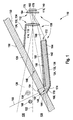
- FIG. 1 a first embodiment of a camera module 110 according to the invention is shown in a sectional view from the side, on the basis of which an embodiment of a method according to the invention is to be illustrated.
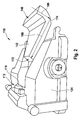
- FIG. 2 shows this embodiment in a perspective view.
- the camera module 110 corresponds in its basic structure and its operation, for example, substantially in DE 10 2004 015 040 A1 described camera module, so that reference can be made to this document with regard to possible uses and possible further embodiments.
- the camera module 110 includes a camera 112 with an in FIG. 1 only indicated imaging optics 114 with a lens 116. Furthermore, the camera 112 includes a spatially resolving imaging sensor 118, which is also referred to as an imager. This spatially resolving imaging sensor 118 may include, for example, a CCD chip and / or a CMOS chip. The camera 112 has a receiving area 120 whose boundary is in FIG. 1 symbolically represented by dashed lines. This receiving area 120 has an optical axis 122.
- the camera module 110 is in the in FIG. 1 illustrated embodiment integrated in a housing 124, which in FIG. 1 is merely indicated.
- the camera module 110 can be integrated, for example, behind a windshield 126 of a motor vehicle, for example in the region of an interior mirror of the motor vehicle, in order to detect a traffic space 128 in an environment 130 of the motor vehicle by means of the reception area 120.
- the housing 124 further includes an in which in FIG. 1 illustrated embodiment of multi-part stray light aperture 132.
- This lens hood is designed in two parts in this embodiment and has an upper lens hood 134 and a lower lens hood 136.
- an integrated optical secondary sensor 138 which, in contrast to many known from the prior art secondary sensors in the in FIG. 1 illustrated embodiment is integrated into the housing 124 of the camera module 110.
- This optical secondary sensor 138 is configured in the illustrated embodiment, for example, as a rain sensor or for other, above or below described in more detail functions.
- the optical secondary sensor comprises an optical sensor 140, which in this exemplary embodiment is configured at least partially identically to the spatially resolving imaging sensor 118, so that the secondary optical sensor 138 and the camera 112 share the spatially resolving imaging sensor 118.
- the optical secondary sensor 138 has a separate optical sensor.
- the secondary optical sensor 138 includes a light guide 142 configured to receive an optical signal in the form of secondary light (in FIG. 1 designated by the reference numeral 144) from a coupling-in area 146 of the camera module 110 to the optical sensor 140.
- the light guide 142 has a light entrance 148, which is arranged near an inner surface 150 of the windshield 126, so that by means of the optical secondary sensor 138, for example, particles 152 and / or raindrops 154 on an outer surface 156 and / or mist 158 or Hail 160 or raindrops in an environment 130 of the motor vehicle are observable.
- Other functions are described below or are, for example, the DE 10 2004 015 040 A1 removable.
- the light guide 142 is integrated in the illustrated embodiment as part of the lens hood 132 in the lower lens hood 136. Alternatively or additionally, the light guide 142 may also be arranged, for example, wholly or partially adjacent to the scattered light diaphragm 132. If the light guide 142 is used as part of the scattered light diaphragm 132, it is particularly preferred if this at least one of its surfaces 162, 164 is provided with a light reflection suppressing property, for example, to attenuate stray portions of the primary light of the camera 112. For this purpose, for example, a coating 166 and / or a roughening can be provided.
- the secondary optical sensor 138 may further include at least one light source 168, which is incorporated in FIG FIG. 1 only symbolically indicated.
- This light source 168 may, for example, comprise one or more light-emitting diodes (LEDs) which emit, for example, continuously and / or pulsed in the visible and / or in the infrared and / or in the ultraviolet spectral range.
- LEDs light-emitting diodes
- Other types of light sources 168 are conceivable.
- the optical secondary sensor 138 also optionally, have a coupling element 170, which in FIG.
- a coupling element 170 may, for example, on the DE 10 2004 015 040 A1 and / or to one of the embodiments described below, for example according to FIG. 6 , to get expelled.
- a deflecting element 174 which may be configured in this case, for example, as a mirrored outer surface of the light guide 142 in the region of the light entrance 148 and / or as a totally reflecting prism surface.
- This in FIG. 1 illustrated embodiment of the camera module 110 is due to this deflecting element 174 able to the first optical element of DE 10 2004 015 040 A1 to renounce, which is there to control the secondary light and to focus on it is required.
- the task of a deflection 174 of the secondary light 144 is taken over by the light guide 142 itself or its deflection element 174 or a separate deflection element.
- the optical fiber 142 by integrating the optical fiber 142 into the lens hood 132 of FIG. 1 shown construction are made compact and robust, wherein the optical fiber 142 itself attenuates the scattering components of the primary light due to its surface condition.
- the light guide 142 may also have imaging properties. For example, it can collimate the secondary light 144 transmitted by it and image it onto the optical sensor 140, for example as a cleverly designed shape of the light entrance 148 and / or the light exit 172 and optionally by imaging properties of the deflection element 174 (eg a curved mirror surface) sharpest possible picture.
- imaging properties for example, it can collimate the secondary light 144 transmitted by it and image it onto the optical sensor 140, for example as a cleverly designed shape of the light entrance 148 and / or the light exit 172 and optionally by imaging properties of the deflection element 174 (eg a curved mirror surface) sharpest possible picture.
- the embodiment shown is a long, flat secondary light guide for the secondary light 144.
- a corresponding stray light aperture function can be realized on the surface of the light guide 142, for example by the coating 166 and / or the roughening.
- the separation between the secondary light 144 and the primary light path of the camera 112 can be achieved in particular substantially solely by the thinly configured coating 166 on one or both surfaces 162, 164 of the light guide 142.
- an aperture 176 which is optionally present in many camera modules 110 and which is incorporated in FIG FIG.
- this spatial separation may preferably be an image by the camera 112 in the form of a primary image area 178 and an image from a field of view 180 (in FIG. 1 merely indicated) in the form of a secondary image area 182 can be determined solely by an image analysis. Accordingly, it is possible to dispense with the optional aperture 176, which can be applied to a glass lid 184, for example, which is difficult to adjust.
- the lens hood 132 may be wholly or partially located as a separate component adjacent the elongated light guide 142.
- the secondary light 144 can be collimated, and stray light in the secondary light 144 can be suppressed by the above-described surface design and surface reflections can be greatly attenuated.
- the coating 166 and / or the roughening of the scattered light diaphragms 134 and / or 136 can be used effectively. This is particularly advantageous if the optical secondary sensor 138, as illustrated above, comprises a light emitting diode as a light source 168.
- FIG. 2 is in perspective the in FIG. 1 schematically shown in a sectional view of the side of the embodiment of the camera module 110 shown in a possible implementation.
- a reflective deflection of the secondary light 144 in the form of a primed and / or mirrored deflecting element 174 is realized in turn.
- This in FIG. 2 illustrated model is not to scale and not optimized with respect to the primary function of the camera 112.
- the arrows 186, 188 denote the light path of the secondary light 144, on which this propagates from the light entrance 148 to the light exit 172. That of the (in FIG.
- windshield 126 outgoing secondary light 144 passes through the light entrance 148 in the light guide 142, is deflected at the reflective surface of the deflecting element 174 and leaves the light guide 142 from the light exit 172 in the direction of the lens 116 of the camera.
- the possible funnel-shaped configuration of the light guide 142 is shown, by which it exerts a collimating effect on the secondary light 144.
- the light guide 142 is preferably wider at its light entry 148, at least in one dimension, than at the light exit 172.
- All surfaces of the optical waveguide 142 are configured in such a way that light reflections within the optical waveguide 142 lead to the greatest possible attenuation as achieved, for example, by roughening or a modified refractive index at the edge. Accordingly, the surfaces 162, 164 of the light guide 142 may be configured. The roughening and / or a corresponding coating 166 on the surfaces 162 and / or 164 may in turn also perform the above-described dual function of simultaneous suppression of stray light components in the secondary light 144 and in the primary light.
- the scattered light diaphragm 132 is thus at least piecewise identical to one or both of these surfaces 162, 164. From the consideration in FIG. 1 It is clear that the secondary light is strongly collimated under these conditions, especially when the height of the light guide in relation to the length of the light path in the light guide is particularly small.
- FIG. 3 is, in similar representation too FIG. 1 , A second embodiment of a camera module 110 according to the invention shown schematically.
- the embodiment according to FIG. 3 largely corresponds to the embodiment according to FIG. 1 so that to a large extent reference may be made to the above description.
- the in FIG. 3 illustrated embodiment differs the light guide 142 in the region of the light entrance 148 of the in FIG. 1 illustrated embodiment.
- the light guide 142 in the in FIG. 3 illustrated embodiment instead of bending in accordance with FIG. 1 an imaging element 190 in the form of a prism-shaped end 192.
- this prism-shaped end 192 can serve as a deflecting element 174, since secondary light 144 is refracted at the light entrance 148 by this prism-shaped end 192 in such a way that rays entering from the direction of the viewing area 180 occur Fiber optic 142 can propagate.
- a reflective surface in the region of the deflecting element 174 become.
- such reflective surfaces can also be provided in addition.
- the secondary light 144 can be coupled and disconnected very close to the windshield 126, so that preferably from the inside 150 of the windshield 126 no extraneous light can get into the light guide 142. Furthermore, in the vicinity of the windshield 126, a viewing direction can be taken upwards, which in FIG. 1 and in FIG. 3 can be seen on the opposite direction of the optical axis 122 inclined upward direction of the field of view 180 of the secondary sensor 138. In this way, for example, an ambient brightness determination, such as, for example, a solar load detection, and / or a brightness determination of the sky can be carried out simultaneously to a function of rain detection.
- an ambient brightness determination such as, for example, a solar load detection, and / or a brightness determination of the sky can be carried out simultaneously to a function of rain detection.
- a bundling of the secondary light 144 or an image of the same can be achieved.
- the outer pane surface 156 of the windshield 126 and / or particles 152 or raindrops 154 may be sharply imaged on the position-sensitive imaging sensor 118 and / or the optical sensor 140 of the secondary optical sensor 138 as a secondary image in the secondary image area 182.
- the structures of objects such as in the FIGS. 1 and 3 shown in the form of mist 158 and / or hail 160, which are arranged closely above the windshield 126, are distinguished by their contour.
- the camera module 110 may include integrated or decentralized control suitable for such Evaluation is set up, for example, by programming. Such a control is not shown in the figures.
- imaging elements may be provided, for example an imaging element at the light exit 172.
- other types of imaging elements may be provided. If, for example, the mirror surface of the deflection element 174 in FIG. 1 designed curved, so this can act as an imaging element at the light entrance 148.
- the prism-shaped end 192 at the light entrance 148 according to the embodiment in FIG. 3 be designed as a curved prism-shaped element and thus, for example, have focusing properties.
- the light guide 142 may be configured in this manner or otherwise to provide a height-to-width ratio of the viewing area 180, such as the area actually observed on the windshield 126, to the height-to-width ratio of the secondary image area on the spatial resolution imaging sensor 118, preferably to reduce.
- the light guiding of the secondary light 144 preferably takes place in such a way that the image of this secondary light 144 lies on the secondary image area 182 next to the lower part of the primary image in the primary image area 178, which is mostly considerably darker than the upper part of this primary image. As a result, a better signal separation can be made possible as a rule.
- FIG. 4 an embodiment of a light guide 142 is shown, in which the light entrance 148 is configured in the form of a Multiprismas 194.
- This multiprism 194 is designed such that it acts as an imaging element 190, similar to a Fresnel lens.
- the multiprism 194 has as many prism surfaces as possible. As in FIG.
- the angle of the prism surfaces relative to the windshield 126 should be selected such that the incident radiation of the secondary light is already at the disk in a suitable manner in the direction of the light exit 172 or toward the image pickup lens 114 and the Spatial imaging sensor 118 is bundled.
- Such bundling by means of multiprisms can also be implemented alternatively or additionally in the exemplary embodiments illustrated in the other figures.
- FIG. 4 again to recognize the optional funnel-shaped profile of the light guide 142.
- the light entrance 148 is equipped with an imaging element 190 by way of example.
- the light exit 172 that is to say the part of the light guide 142 facing the image recording optical system 114 or the spatially resolving imaging sensor 118, can also be equipped with such an imaging element 190.
- FIG. 5 this figure again shows a plan view of the light guide 142, analogous to the representation according to FIG FIG.
- the entire light guide 142 can be designed to be imaging, for example by a corresponding design of the imaging element 190 at the light exit 172
- the imaging element 190 at the light exit 172 designed as a lens element 196.
- other embodiments of the imaging element 190 are possible, for example, again a configuration as a multiprism.
- the secondary image as a sharp image of the objects on the disk surface 156 of the windshield 126 on the map spatially resolved imaging sensor 118.
- the at least one imaging element 190 can in turn also change or adapt a height-to-width ratio.
- FIG. 3 in contrast to FIG. 1 , no light source 168 and no coupling 170 shown. However, such elements 168, 170 may optionally also be provided in this embodiment.
- FIG. 6 An example of a possible light coupling by means of coupling elements 170 is shown in FIG. 6 shown.
- This figure again shows, similar to the representation according to FIG. 4 , A top view of the light guide 142.
- This light guide 142 may be coated on one or more surfaces 198 in turn wholly or partially.
- deflecting elements 174 for example in the form of reflections, can again be provided, as in FIG FIG. 6 indicated.
- the light guide 142 has in the in FIG. 6 illustrated embodiment, a recess 200.
- This recess 200 may be continuous or merely formed as a recess in the light guide 142.
- this recess 200 can in turn also be wholly or partially provided with a coating, for example, a coupling of light (in FIG. 6 denoted by reference numeral 202) of the light source 168 immediately in the direction of the light exit 172 to avoid.
- the light source 168 is arranged in the region of two lens-shaped coupling elements 170, which have the light source 168 facing, preferably uncoated surfaces. In this way, light from the light source 168 is coupled into the light guide 142 in the direction of the light entrance 148 and the windshield 126, penetrates the windshield 126, and is reflected on the outer surface 156 of the windshield 126 and re-coupled into the light guide 142. By the said deflecting elements 174, this light is correspondingly towards the light exit 172 (in FIG. 6 not shown) steered and optionally focused.
- FIG. 6 illustrated coupling mechanism for coupling the light 202 of the light source 168 represents only one possible embodiment of a light coupling.
- an additional light source 168 can also be dispensed with completely, so that, for example, only the ambient light or a spotlight is used as illumination.
- the use of an additional light source 168 is preferred because in this way a light power measurement is made possible, which emanates from a known light output and determines, for example, their decrease as a measured variable. This is usually difficult for less well-defined light sources, such as ambient light, for example.
- this technical hurdle could be circumvented, for example, by the use of additional sensors for determining the primary intensity and / or power of the ambient light and / or the headlight, so that in principle this possibility can also be realized.
- the at least one light source 168 may, as in FIG. 6 shown, may be disposed within the light guide 142, wherein, however, as an alternative or in addition, for example, an arrangement below the light guide 142 is possible. With the aid of the light source 168, it is also possible, for example, to illuminate objects on the windshield 126 with a suitable arrangement, for example while avoiding total reflections. Due to the surface design of the light guide 142, for example, the in FIG. 6 shown surface configuration, it can be prevented that this light 202 of the light source 168 passes directly to the lens 116 of the image pickup optics 114 without that light 202 has illuminated objects on the disc.
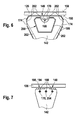
- FIG. 6 only a single light source 168 is shown.
- a plurality of light sources 168 such as in an in FIG. 7 illustrated embodiment is illustrated.
- the secondary image region 182 or the used regions on the secondary image region 182 are disjoint.
- a plurality of separate regions in the secondary image area 182 may be used to represent the various images of the propagation paths of the light 202 of the light sources 168. In this way, for example, images can be used redundantly.
- the light sources 168 are each optionally provided with shields 204, which also act as coupling elements 170 and which, for example, again prevent direct light propagation of the light of the light sources 168 toward the light exit 172.
- These shields 204 may also have imaging effects, for example, to focus the light 202 of the light sources 168.
- FIG. 7 the light entrance 148 again, similar to the embodiment according to FIG. 4 , optionally configured as a multiprism 194.
- the light source 168 or the plurality of light sources can be configured in different ways and can include, for example, continuous light sources and / or flash light sources.
- one or more light emitting diodes and / or other types of light sources 168 may be provided for this purpose.
- FIG. 8 is an embodiment of an image-sensitive surface of a spatially resolving imaging sensor 118, which is also used as an optical sensor 140 of the secondary optical sensor 138, shown.
- the spatially resolving imaging sensor 118 has a resolution of 640x480 pixels in this embodiment.
- the image area is subdivided into a primary image area 178, in which the receiving area 120 of the camera 112 is imaged, and a secondary image area 182, in which the viewing area 180 of the secondary optical sensor 138 is imaged.
- the secondary image area 182 is selected in its width to height ratio such that this ratio is very large. In the example in FIG. 8 this is a ratio of 640 to 30 pixels, ie approximately a ratio of 21.
- the transition between the primary image area 178 and the secondary image area 182 on the spatially resolving imaging sensor 118 should be as clearly as possible separated by the image processing, so that the sensory area, and if possible only this, as much as possible secondary light 144 receives.
- the windshield 126 should not typically have such a large width-to-height ratio, for example, raindrops produce a round image to a first approximation. This clarifies the meaning and the advantages that the design of the light guide 142 has as a width-to-height ratio changing element.
- FIG. 8 as an alternative or in addition to the rectangular secondary image area 182 feasible embodiment, nor a plurality disjunkter secondary image areas shown 182, which are exemplified as four dashed ovals.
- This example is intended to clarify that the secondary image area 182 does not necessarily have to be completely separated from the primary image area 178.
- the spatial separation of the light of a plurality of light sources 168 and / or the splitting of the luminous flux of the light 202 of these light sources 168, which, for example, above with reference to FIGS. 7 and 8th For example, to generate such disjoint secondary image areas 182 as described in U.S. Pat FIG. 8 dashed lines are used.
- these secondary image areas 182 are located in a region of the primary image area 178, which is usually dark, they can be separated from the image of the camera 112 by appropriate image processing measures. Also, a temporal scheme for separation can be used, as described in more detail below.
- Images on the spatial resolution imaging sensor 118 may in many cases be taken, for example, line by line. Such methods are often referred to as "rolling shutter".
- rolling shutter In this case, for example, by synchronizing the at least one light source 168 with a recording algorithm of the spatially resolving imaging sensor 118, it is possible for a reflection image from the windshield 126 to be clearly assigned to a specific range of image lines of the spatially resolving imaging sensor 118.
- this method can also be used within the scope of the camera module 110 according to the invention.
- the method has the disadvantage that, if this area of the secondary image 182 coincides with a brightly illuminated area of the primary image area 178, an evaluation is difficult at these locations.
- a line-by-line redundancy can also be achieved by short-term repeated illumination of the windshield 126, as described by the spatial redundancy provided by a plurality of light paths and / or multiple light sources. This is shown schematically in the image acquisition plan in FIG. 9 exemplified.
- FIG. 9 three time axes are designated by t.
- t In each case at times t0 begins an image recording, wherein the distance T between successive times t0 is also referred to as image repetition time.
- a conventional image-synchronous exposure scheme is applied, which in principle can also be implemented within the scope of the present invention. This is achieved by an optional synchronization (in FIG. 9 denoted by reference numeral 208), an exposure pulse is switched in which the light intensity of the light source 168 is switched from zero (or a small offset) to an intensity 10 in the short term. During this time, image information of the secondary optical sensor 138 is captured.
- FIG. 9 an image pickup method with a flashlight pattern 212 indicated by numeral 210 is shown. Again, this flash pattern 212 may again (in FIG. 9 not shown) at the beginning t0 of the image recording to be synchronized.
- FIG. 8 A result of such imaging of the secondary optical sensor 138 having a flash pattern 212 is also shown in FIG. 8 shown here, optionally here in addition to the splitting of the secondary image area 182 into a plurality of partial areas, which in FIG. 8 are shown in dashed lines. It can be seen that the in FIG. 8 in each case designated by the reference numeral 214, the total irradiated area of the subareas of the secondary image area 182 is subdivided into a plurality of strip-type used areas 216. In this way are in the in FIG. 8 shown image redundant information of the optical secondary sensor 138 included, which can be separated, for example, computationally.
- the used areas 216 occur as disturbances in the primary image area 178, the payload of which can be determined, for example, by means of appropriate correlation techniques.
- the available image-sensitive surface of the position-sensitive imaging sensor 118 can be optimally used for both use the primary function of the camera 112 as well as the secondary function of the optical secondary sensor 138.
Landscapes
- Engineering & Computer Science (AREA)
- Multimedia (AREA)
- Signal Processing (AREA)
- Studio Devices (AREA)
Abstract
Description
Die Erfindung geht aus von bekannten Kameramodulen, welche bereits heute für vielfältige Einsatzgebiete im Kraftfahrzeugbereich eingesetzt werden. Insbesondere lassen sich derartige Kameramodule für eine Fahrzeugumfelddetektion einsetzen, also für die Beobachtung von Aufnahmebereichen in der Umgebung des Kraftfahrzeugs. Die Kameramodule sind insbesondere für den Einsatz hinter einer Windschutzscheibe eines Kraftfahrzeugs, insbesondere im Bereich des Innenspiegels, einsetzbar. Grundsätzlich lassen sich die im Rahmen der vorliegenden Erfindung beschriebenen Kameramodule jedoch auch für andere Einsatzzwecke im Kraftfahrzeugbereich oder in anderen Bereichen einsetzen.The invention is based on known camera modules, which are already used today for a variety of applications in the automotive sector. In particular, such camera modules can be used for vehicle surroundings detection, that is to say for the observation of reception areas in the surroundings of the motor vehicle. The camera modules can be used in particular for use behind a windshield of a motor vehicle, in particular in the region of the interior mirror. In principle, however, the camera modules described within the scope of the present invention can also be used for other purposes in the automotive sector or in other fields.
An Kameras zur Fahrzeugumfelddetektion werden vermehrt vielseitige Ansprüche gestellt. So werden in
Die in
Es werden daher ein Kameramodul für den Einsatz in einem Kraftfahrzeug und ein Verfahren zur optischen Überwachung eines Umgebungsbereichs eines Kraftfahrzeugs vorgeschlagen, welche die Nachteile der aus dem Stand der Technik bekannten Kameramodule und Verfahren zumindest weitgehend vermeiden und die oben beschriebenen Verbesserungspotenziale ausnutzen. Das Kameramodul kann in weiten Teilen ähnlich zu dem in
Das Kameramodul umfasst mindestens eine Kamera mit einem ortsauflösenden Bildgebungssensor, wobei die Kamera zur Erfassung eines Aufnahmebereichs eingerichtet ist. Zu diesem Zweck kann die Kamera beispielsweise eine bildgebende Optik, insbesondere mindestens ein Objektiv mit mindestens einer Linse, umfassen. Der Aufnahmebereich kann insbesondere ein Aufnahmebereich im Umgebungsbereich des Kraftfahrzeugs sein, so dass das Kameramodul beispielsweise, wie oben beschrieben, hinter der Windschutzscheibe oder einer sonstigen Scheibe des Kraftfahrzeugs montiert werden kann, um einen Verkehrsraum der Umgebung des Kraftfahrzeugs zu beobachten.The camera module comprises at least one camera with a spatially resolving imaging sensor, wherein the camera is set up to detect a recording area. For this purpose, the camera may comprise, for example, an imaging optical system, in particular at least one objective with at least one lens. The receiving area may in particular be a receiving area in the surrounding area of the motor vehicle, so that the camera module, for example, as described above, behind the windshield or a other disc of the motor vehicle can be mounted to observe a traffic space of the environment of the motor vehicle.
Die Kamerafunktion des Kameramoduls kann einer oder mehreren der oben beschriebenen Primärfunktionen dienen, beispielsweise einer Verkehrszeichenerkennung, einer Fahrspurerkennung, einer Objekterkennung, einer Ausleuchtungssteuerung, einer Messung der Intensität des von vorne einfallenden Lichts oder ähnlichen Funktionen.The camera function of the camera module can serve one or more of the primary functions described above, such as traffic sign recognition, lane recognition, object recognition, illumination control, intensity measurement of incident light, or similar functions.
Neben dieser Kamera zur Durchführung der mindestens einen Primärfunktion umfasst das Kameramodul weiterhin mindestens einen in dem Kameramodul integrierten optischen Sekundärsensor zur Wahrnehmung mindestens einer Sekundärfunktion. Wie oben beschrieben, kann diese Sekundärfunktion beispielsweise eine oder mehrere der Funktionen einer Regensensorik, einer Lichtsensorik, einer Betauungs- oder Beschlagsdetektion, einer Detektion der Sonneneinstrahlrichtung und Sonneneinstrahlungsstärke oder ähnliche Sekundärfunktionen umfassen.In addition to this camera for carrying out the at least one primary function, the camera module further comprises at least one integrated in the camera module optical secondary sensor for sensing at least one secondary function. As described above, this secondary function may comprise, for example, one or more of the functions of a rain sensor system, a light sensor system, a condensation or fog detection, a detection of the solar irradiation direction and solar radiation intensity or similar secondary functions.
Unter einer Integration ist dabei eine Ausgestaltung zu verstehen, bei welcher der mindestens eine optische Sekundärsensor beispielsweise in einem Gehäuse des Kameramoduls mit integriert ist. Insbesondere kann der mindestens eine Sekundärsensor ganz oder teilweise innerhalb einer Streulichtblende des Kameramoduls angeordnet sein. Damit unterscheidet sich das vorgeschlagene Kameramodul von aus früheren Anwendungen bekannten Modulen, bei welchen beispielsweise eine Regen-Licht-Sensorik neben einer Videokamera mit einer Streulichtblende eingesetzt wird, also als separate Komponente.An integration is an embodiment in which the at least one optical secondary sensor is integrated, for example, in a housing of the camera module. In particular, the at least one secondary sensor can be arranged wholly or partly within a scattered-light diaphragm of the camera module. Thus, the proposed camera module differs from known from earlier applications modules in which, for example, a rain-light sensor is used in addition to a video camera with a lens hood, so as a separate component.
Der Sekundärsensor weist mindestens einen optischen Sensor und mindestens einen Lichtleiter auf. Der optische Sensor dient der Erfassung optischer Signale des Sekundärsensors und kann dabei als einfacher optischer Sensor ausgestaltet sein, also beispielsweise als Fotodiode oder ähnliches lichtempfindliches Halbleiterbauelement. Wie unten näher ausgeführt wird, kann dieser optische Sensor jedoch auch wiederum einen ortsauflösenden optischen Sensor umfassen. Beispielsweise kann dieser optische Sensor wiederum, wie auch der ortsauflösende Bildgebungssensor der Kamera, einen CCD-Chip, einen CMOS-Chip oder andere Arten ortsauflösender Bildgebungssensoren bzw. Bildgebungschips umfassen. Wie unten näher ausgeführt wird, ist es besonders bevorzugt, denselben ortsauflösenden Bildgebungssensor sowohl für die Kamera als auch für den optischen Sekundärsensor einzusetzen.The secondary sensor has at least one optical sensor and at least one light guide. The optical sensor is used to detect optical signals of the secondary sensor and can be designed as a simple optical sensor, so for example as a photodiode or similar photosensitive semiconductor device. However, as explained in more detail below, this optical sensor can in turn also comprise a spatially resolving optical sensor. By way of example, this optical sensor, like the camera's resolving imaging sensor, may in turn comprise a CCD chip, a CMOS chip or other types of spatially resolving imaging sensors or imaging chips include. As will be explained in more detail below, it is particularly preferred to use the same spatially resolving imaging sensor for both the camera and the secondary optical sensor.
Unter einem Lichtleiter ist dabei eine Vorrichtung zu verstehen, welche in der Lage ist, optische Signale in Form elektromagnetischer Wellen im sichtbaren und/oder infraroten und/oder ultravioletten Spektralbereich über eine vorgegebene Übertragungsstrecke zu übertragen. Dementsprechend ist der Begriff des Lichtleiters im Rahmen der vorliegenden Erfindung weit zu fassen. Beispielsweise kann der Lichtleiter ein Element sein oder umfassen, welches Licht im klassischen Sinne leitet. Der Lichtleiter kann somit insbesondere ein auf interner Totalreflexion basierender Lichtleiter sein bzw. einen derartigen Lichtleiter umfassen. Grundsätzlich umfasst der Begriff jedoch auch andere Übertragungsanordnungen zum gerichteten Übertragen von Licht, vorzugsweise unter Unterdrückung von Streuungen. Beispielsweise könnte Luft oder Vakuum als Übertragungsmedium in der Übertragungsstrecke fungieren, wobei am Anfang und/oder Ende der Übertragungsstrecke mindestens ein optisches Element vorgesehen sein kann, beispielsweise mindestens ein Spiegel und/oder mindestens ein Prisma und/oder mindestens eine Linse. Weiterhin kann am Anfang und/oder Ende der Übertragungsstrecke beispielsweise auch mindestens eine Blende, beispielsweise mindestens eine Streulichtblende, vorgesehen sein. Der Lichtleiter kann weiterhin eine oder mehrere Wände umfassen, welche die Übertragungsstrecke seitlich abgrenzen und als mechanische Stabilisierung dienen, beispielsweise als mechanische Stabilisierung der Streulichtblende. Beispielsweise kann der Lichtleiter somit einfach als langgestreckte Streulichtblende ausgestaltet sein, mit mindestens einer Streulichtblende am Anfang und/oder Ende der Übertragungsstrecke und mechanisch stabilisierenden Wänden. Allgemein ist also unter einem Lichtleiter im Sinne der vorliegenden Erfindung lediglich eine langgestreckte, eine Streuung unterdrückende Übertragungsstrecke zu verstehen. Der Lichtleiter kann dabei aus geeigneten Materialien hergestellt sein, beispielsweise aus Glas oder, was im Rahmen der vorliegenden Erfindung bevorzugt ist, aus einem oder mehreren Kunststoffen. Auch Kombinationen verschiedener Werkstoffe sind möglich.Under a light guide is to be understood a device which is capable of transmitting optical signals in the form of electromagnetic waves in the visible and / or infrared and / or ultraviolet spectral range over a predetermined transmission path. Accordingly, the term of the light guide is to be understood in the context of the present invention. For example, the light guide may be or include an element that conducts light in the classical sense. The optical waveguide can thus be in particular a light guide based on internal total reflection or comprise such a waveguide. In principle, however, the term also encompasses other transmission arrangements for the directional transmission of light, preferably with the suppression of scattering. For example, air or vacuum could act as a transmission medium in the transmission path, wherein at least one optical element may be provided at the beginning and / or end of the transmission path, for example at least one mirror and / or at least one prism and / or at least one lens. Furthermore, at the beginning and / or end of the transmission path, for example, at least one diaphragm, for example at least one stray light diaphragm, may be provided. The optical waveguide may further comprise one or more walls which laterally delimit the transmission path and serve as mechanical stabilization, for example as mechanical stabilization of the scattered light diaphragm. For example, the optical waveguide can thus be configured simply as an elongated scattered-light diaphragm, with at least one stray-light diaphragm at the beginning and / or end of the transmission path and mechanically stabilizing walls. In general, therefore, an optical waveguide in the sense of the present invention is to be understood merely as an elongate, scatter-suppressing transmission path. The light guide can be made of suitable materials, for example of glass or, which is preferred in the context of the present invention, of one or more plastics. Also combinations of different materials are possible.
Der Lichtleiter soll eingerichtet sein, um das optische Signal von einem Einkopplungsbereich des Kameramoduls zu dem optischen Sensor zu leiten. Der Einkopplungsbereich des Kameramoduls kann beispielsweise eine Öffnung des Kameramoduls hin zu dem Aufnahmebereich umfassen, beispielsweise eine Öffnung eines Gehäuses des Kameramoduls, beispielsweise hin zu einer Windschutzscheibe des Kraftfahrzeugs. Der Lichtleiter muss dabei das optische Signal des optischen Sekundärsensors nicht auf dem vollständigen Weg von diesem Einkopplungsbereich hin zum optischen Sensor leiten, sondern lediglich auf mindestens einem Teilstück dieses optischen Weges. So kann beispielsweise, wie unten anhand von Ausführungsbeispielen näher erläutert wird, ein Lichteintritt auch beabstandet von der Windschutzscheibe angeordnet sein, und ein Lichtaustritt des Lichtleiters beabstandet von dem optischen Sensor. Zumindest ein Teilstück des optischen Weges soll jedoch den Lichtleiter umfassen.The light guide should be arranged to pass the optical signal from a coupling-in area of the camera module to the optical sensor. The coupling region of the camera module can, for example, an opening of the Camera module towards the receiving area include, for example, an opening of a housing of the camera module, for example, towards a windshield of the motor vehicle. The optical fiber does not have to guide the optical signal of the optical secondary sensor on the complete path from this coupling region to the optical sensor, but only on at least a portion of this optical path. Thus, for example, as explained in more detail below with reference to exemplary embodiments, a light entry may also be arranged at a distance from the windscreen, and a light exit of the light guide spaced from the optical sensor. However, at least a portion of the optical path should encompass the light guide.
Das Kameramodul kann auf verschiedene Weisen vorteilhaft optional ausgestattet sein. So kann das Kameramodul insbesondere eine Streulichtblende zur Verminderung der Einkopplung von Streulicht in den Bildgebungssensor bzw. in die Kamera umfassen. Der Lichtleiter kann dabei zumindest teilweise in diese Streulichtblende integriert sein, also beispielsweise einen Bestandteil dieser Streulichtblende bilden. Beispielsweise kann der Lichtleiter mindestens eine eine Lichtreflexion unterdrückende Oberfläche aufweisen, beispielsweise eine aufgeraute und/oder eine beschichtete Oberfläche.The camera module can advantageously be optionally equipped in various ways. In particular, the camera module can include a scattered light diaphragm for reducing the introduction of scattered light into the imaging sensor or into the camera. The light guide can be at least partially integrated in this lens hood, so for example, form a part of this lens hood. By way of example, the light guide can have at least one surface which suppresses light reflection, for example a roughened and / or a coated surface.
Weiterhin kann der Lichtleiter mindestens ein Umlenkelement aufweisen, also ein Element, welches eingerichtet ist, um eine Richtung des Strahlenverlaufs durch den Lichtleiter zu ändern. Dieses Umlenkelement, welches unten anhand von Beispielen näher ausgeführt wird, kann ausgestaltet sein, um einen Sichtbereich des optischen Sekundärsensors gegenüber einem Blickwinkel der Kamera, also beispielsweise gegenüber einer optischen Achse der Kamera, zu verkippen. Insbesondere kommt eine Betrachtung eines über dem Kraftfahrzeug angeordneten Umgebungsbereichs auf diese Weise in Betracht, so dass beispielsweise ein Sensor zur Erfassung einer Sonneneinstrahlung bzw. einer Umgebungsbeleuchtung (Solar-load) realisiert werden kann.Furthermore, the optical waveguide can have at least one deflecting element, that is to say an element which is set up to change a direction of the beam path through the optical waveguide. This deflection element, which is explained in more detail below by way of examples, can be configured to tilt a viewing region of the optical secondary sensor with respect to a viewing angle of the camera, that is to say, for example, with respect to an optical axis of the camera. In particular, consideration of an environmental area arranged above the motor vehicle is considered in this way, so that, for example, a sensor for detecting solar radiation or ambient lighting (solar load) can be realized.
Das Umlenkelement kann beispielsweise ein Prisma, insbesondere eine als Prisma ausgestaltete Endfläche des Lichtleiters, einen Spiegel, eine zumindest teilweise verspiegelte Oberfläche des Lichtleiters oder ähnliche Umlenkelemente umfassen. Das Umlenkelement kann einstückig mit dem übrigen mindestens einen Lichtleiter ausgestaltet sein, also beispielsweise in diesen Lichtleiter integriert sein. Alternativ oder zusätzlich kann dieses Umlenkelement jedoch auch lediglich mit dem Lichtleiter verbunden sein, beispielsweise auf diesen Lichtleiter aufgesetzt sein.The deflecting element may for example comprise a prism, in particular an end face of the light guide designed as a prism, a mirror, an at least partially mirrored surface of the light guide or similar deflecting elements. The deflecting element may be designed in one piece with the other at least one light guide, that is, for example integrated in this light guide be. Alternatively or additionally, however, this deflection element can also be connected only to the light guide, for example, be placed on this light guide.
Der Lichtleiter kann weiterhin mindestens eine optische Abbildungseigenschaft aufweisen, also eine Eigenschaft, bei welcher ein optisches Signal in Form mindestens eines Ursprungsbildes durch den Lichtleiter in ein Bild umgewandelt wird. Diese optische Abbildungseigenschaft kann beispielsweise eine kollimierende Eigenschaft, eine fokussierende Eigenschaft, eine Bündelungseigenschaft, eine vergrößernde und/oder verkleinernde Abbildungseigenschaft, eine (wie unten näher ausgeführt wird) Veränderung des Höhen-zu-Breiten-Verhältnisses des Bildes oder ähnliche optische Eigenschaften umfassen.The optical waveguide can furthermore have at least one optical imaging property, ie a property in which an optical signal in the form of at least one original image is converted by the optical waveguide into an image. This optical imaging property may include, for example, a collimating property, a focusing property, a converging property, an enlarging and / or decreasing imaging property, a change in the height-to-width ratio of the image (as explained below), or similar optical properties.
Weiterhin kann der Lichtleiter in dem Einkopplungsbereich einen Lichteintritt aufweisen, welcher mindestens ein erstes bildgebendes Element aufweist. Dieses erste bildgebende Element kann beispielsweise mindestens ein Prisma, ein Multiprisma, insbesondere eine Fresnel-Linse oder ähnliche bildgebende Elemente umfassen. Auch Kombinationen derartiger Elemente sind möglich.Furthermore, the optical waveguide in the coupling-in region can have a light entrance, which has at least one first imaging element. This first imaging element may comprise, for example, at least one prism, a multiprism, in particular a Fresnel lens or similar imaging elements. Combinations of such elements are possible.
Auch an einem Lichtaustritt des Lichtleiters kann mindestens ein zweites bildgebendes Element vorgesehen sein, welches ebenfalls wiederum eines oder mehrere der eben genannten bildgebenden Elemente aufweisen kann.At least one second imaging element can also be provided at a light exit of the light guide, which in turn can likewise have one or more of the imaging elements just mentioned.
Der optische Sensor des optischen Sekundärsensors kann zumindest teilweise identisch mit dem Bildgebungssensor der Kamera sein. Dabei kann beispielsweise der Aufnahmebereich der Kamera als Primärbild auf einen Primärbildbereich des Bildgebungssensors abgebildet werden und der Sichtbereich des optischen Sekundärsensors als Sekundärbild auf einen Sekundärbildbereich des Bildgebungssensors. Der Primärbildbereich und der Sekundärbildbereich können dabei identisch oder zumindest teilweise verschieden ausgebildet sein. Verschiedene Ausgestaltungen werden unten näher erläutert.The optical sensor of the secondary optical sensor may be at least partially identical to the imaging sensor of the camera. In this case, for example, the recording area of the camera can be imaged as a primary image onto a primary image area of the imaging sensor and the viewing area of the optical secondary sensor as a secondary image onto a secondary image area of the imaging sensor. The primary image area and the secondary image area can be identical or at least partially different. Various embodiments will be explained in more detail below.
Insbesondere wenn der Primärbildbereich und der Sekundärbildbereich zumindest teilweise identisch sind, so ist es bevorzugt, wenn das Kameramodul eine Bildaufnahmesteuerung umfasst, welche eingerichtet ist, um mittels einer zeitlichen Aufnahmeabfolge Signale des optischen Sekundärsensors von Signalen der Kamera zu trennen. In diesem Fall und auch in anderen Fällen kann der optische Sekundärsensor beispielsweise eine Blitzlichtbeleuchtung, insbesondere eine synchronisierte Blitzlichtbeleuchtung, aufweisen. Insbesondere kann es sich dabei, wie unten an einem Beispiel näher erläutert wird, um eine Blitzlichtbeleuchtung zur Erzeugung eines Blitzlichtmusters mit mehrfacher Blitzauslösung je Bildwiederholzeit handeln.In particular, if the primary image area and the secondary image area are at least partially identical, then it is preferred if the camera module comprises an image acquisition controller which is set up to record signals of the optical secondary sensor of signals by means of a temporal recording sequence disconnect the camera. In this case, and in other cases, the optical secondary sensor, for example, a flash illumination, in particular a synchronized flash illumination, have. In particular, as will be explained in greater detail below using an example, this may be flash illumination for generating a flash pattern with multiple flash firing per frame repetition time.
Alternativ oder zusätzlich zu der Blitzlichtbeleuchtung kann das Kameramodul allgemein mindestens eine Lichtquelle umfassen, welche beispielsweise auch die Blitzlichtbeleuchtung umfassen kann. In diesem Fall ist es bevorzugt, wenn mindestens eine Einkopplungsvorrichtung zur Einkopplung von Licht der Lichtquelle in den Lichtleiter vorgesehen ist. Damit kann das Licht der Lichtquelle beispielsweise genutzt werden, um den Sichtbereich des optischen Sekundärsensors durch den Lichtleiter hindurch zu beleuchten. Besonders bevorzugt ist es dabei, wenn die Einkopplungsvorrichtung, beispielsweise durch Verwendung entsprechender Blockierelemente oder durch eine geschickte Einkopplung, derart ausgestaltet ist, dass Licht lediglich in Richtung des Einkopplungsbereichs, also in Richtung des Lichteintritts des Lichtleiters, eingekoppelt wird, wohingegen eine Einkopplung bzw. eine Leitung des Lichts der Lichtquelle hin zu dem optischen Sensor zumindest teilweise unterdrückt bzw. vermieden wird. Auf diese Weise kann sichergestellt werden, dass Licht der Lichtquelle nicht unmittelbar in den optischen Sensor gerät und dabei die eigentlich interessanten Signale des optischen Sensors, beispielsweise Reflexionen an Regentropfen und/oder entsprechende Abbilder des Sichtbereichs des optischen Sekundärsensors, überlagert.As an alternative or in addition to the flash illumination, the camera module may generally comprise at least one light source, which may also include, for example, the flash illumination. In this case it is preferred if at least one coupling-in device is provided for coupling light from the light source into the light guide. Thus, the light of the light source can be used, for example, to illuminate the field of view of the optical secondary sensor through the light guide. It is particularly preferred if the coupling device, for example by using appropriate blocking or by a clever coupling, is configured such that light is coupled only in the direction of the coupling region, ie in the direction of the light entrance of the light guide, whereas a coupling or a Conduction of the light of the light source towards the optical sensor is at least partially suppressed or avoided. In this way, it can be ensured that light from the light source does not get directly into the optical sensor and thereby superimposes the actually interesting signals of the optical sensor, for example reflections on raindrops and / or corresponding images of the field of view of the optical secondary sensor.
Insbesondere in dem Fall, in welchem der optische Sensor des optischen Sekundärsensors zumindest teilweise identisch ist mit dem Bildgebungssensor der Kamera, jedoch auch in anderen Fällen, ist es besonders bevorzugt, wenn für den optischen Sekundärsensor zumindest teilweise eine Bildaufnahmeoptik der Kamera mit verwendet wird. So kann beispielsweise Licht aus dem Lichtleiter auf dem Weg zu dem optischen Sensor zumindest teilweise durch diese Bildaufnahmeoptik hindurchtreten. Da in diesem Fall die Bildaufnahmeoptik gleichzeitig optimale abbildende Eigenschaften für den optischen Sekundärsensor und die primäre Kamerafunktion aufweisen muss, ist es in diesem Zusammenhang, wie oben dargestellt, besonders bevorzugt, wenn der Lichtleiter selbst abbildende Eigenschaften aufweist, welche, in Kombination mit den abbildenden Eigenschaften der Bildaufnahmeoptik, für eine optimale Abbildung des optischen Signals auf den optischen Sensor des optischen Sekundärsensors sorgen.In particular, in the case where the optical sensor of the secondary optical sensor is at least partially identical to the imaging sensor of the camera, but also in other cases, it is particularly preferred if for the optical secondary sensor at least partially an image pickup optics of the camera is used. Thus, for example, light from the light guide can pass through the image pickup optics on the way to the optical sensor at least partially. In this case, as shown above, since the image pickup optical system must simultaneously have optimum imaging properties for the secondary optical sensor and the primary camera function, it is particularly preferred if the optical fiber itself has imaging properties which, in combination with the imaging properties Image capture optics, provide for optimal mapping of the optical signal to the optical sensor of the optical secondary sensor.
Das vorgeschlagene Kameramodul weist gegenüber herkömmlichen, dem Stand der Technik entsprechenden Kameramodulen eine Vielzahl von Vorteilen auf. So kann beispielsweise eine Streulichtblende, welche an sich der Primärfunktion zuzuordnen ist, gleichzeitig als lichtleitender, vorwiegend beispielsweise flacher Kanal zur Kollimierung des Lichtsignals geformt sein. Der mindestens eine Lichteintritt und/oder der mindestens eine Lichtaustritt des Lichtleiters können bevorzugt Prismen und/oder bildgebende Elemente enthalten, beispielsweise Prismen, welche sich entsprechend einer Linsenfunktion ergänzen. Weiterhin können Linsen vorgesehen sein, so dass das Bild auf dem optischen Sensor bzw. dem ortsauflösenden Bildgebungssensor beispielsweise auf eine innere und/oder äußere Scheibenoberfläche beispielsweise einer Windschutzscheibe fokussiert wird. Optional kann in die Windschutzscheibe ein zeitliches Muster einer Blitzlichtbeleuchtung eingekoppelt werden, beispielsweise schräg zur Scheibenoberfläche, so dass Regentropfen auf das Licht auskoppeln (Detektion von Lichtverlust wie bei herkömmlichen Regensensoren), oder nahezu senkrecht auf die Scheibenoberfläche, so dass beispielsweise Regen als Reflexbild sichtbar wird. Wie oben dargestellt, können der mindestens eine Lichteintritt bzw. der mindestens eine Lichtaustritt des Lichtleiters beispielsweise Multiprismenstrukturen aufweisen. Derartige Multiprismenstrukturen sind technisch einfach zu realisieren, so dass sich mittels dieser Technik beispielsweise Vergrößerungsoptiken oder andere Arten von Bildprojektoren realisieren lassen.The proposed camera module has a number of advantages over conventional camera modules according to the prior art. Thus, for example, a scattered light aperture, which is assigned to the primary function, at the same time be shaped as a light-conducting, predominantly, for example, flat channel for collimating the light signal. The at least one light entry and / or the at least one light exit of the light guide may preferably contain prisms and / or imaging elements, for example prisms, which complement each other according to a lens function. Furthermore, lenses may be provided, so that the image is focused on the optical sensor or the spatially resolving imaging sensor, for example on an inner and / or outer disc surface, for example, a windshield. Optionally, a temporal pattern of flash illumination may be coupled into the windshield, for example obliquely to the disc surface so that raindrops decouple onto the light (detection of light loss as in conventional rain sensors), or nearly perpendicular to the disc surface so that, for example, rain becomes visible as a reflex image , As illustrated above, the at least one light entry or the at least one light exit of the light guide can have, for example, multiprism structures. Such Multiprismenstrukturen are technically easy to implement, so that can be realized by means of this technique, for example, magnification optics or other types of image projectors.
Insgesamt ermöglicht es das vorgeschlagene Kameramodul in einer oder mehreren der oben beschriebenen Ausführungsformen vorzugsweise, durch ein oder wenige relativ leicht fertigbare Vorsatzteile oder Teile, vorzugsweise ohne die bisher übliche Blitzlichtbeleuchtung bei der Regensensorik in Verbindung mit Software, die Sekundärfunktionen sowohl für eine Regendetektion als auch eine Lichtdetektion mittels eines Bildsensors zu realisieren. So lässt sich beispielsweise für die aus der
Das vorgeschlagene Kameramodul ermöglicht weiterhin eine maximale Ausnutzung der für die Funktion beispielsweise einer Regen-Licht-Sensorik verfügbaren Sensorfläche, beispielsweise des ortsauflösenden Bildgebungssensors. Beispielsweise weisen derartige Regen-Licht-Sensoriken im Allgemeinen Sekundärbildbereiche auf, in welchen das Verhältnis von Breite zu Höhe sehr groß ist. So kann beispielsweise ein Verhältnis von Breite zu Höhe von 640 Pixeln zu 30 Pixeln vorliegen. Der Übergang zwischen dem Primärbildbereich und dem Sekundärbildbereich auf dem ortsauflösenden Bildgebungssensor sollte durch eine nachfolgende Bildbearbeitung möglichst klar trennbar sein. Daher sollte das Sekundärlicht des optischen Sekundärsensors beim Auftreffen auf den ortsauflösenden Bildgebungssensor möglichst derart geformt sein, dass die sensierende Fläche dieses ortsauflösenden Bildgebungssensors, welche den Sekundärbildbereich aufnimmt, und nur diese, möglichst gleichmäßig viel Sekundärstrahlung des optischen Signals des optischen Sekundärsensors aufnimmt. In dem genannten Beispiel ist dies ein Verhältnis von ca. 21. Die beobachtete Fläche des Sichtbereichs des optischen Sekundärsensors, beispielsweise auf der Scheibe bzw. Windschutzscheibe des Kraftfahrzeugs, sollte hingegen in der Regel ein nicht derart großes Breiten-zu-Höhen-Verhältnis aufweisen, da beispielsweise Regentropfen in erster Näherung ein rundes Bild erzeugen. Mittels bildgebender Eigenschaften des Lichtleiters bzw. bildgebender Elemente am Lichteinlass und/oder am Lichtauslass des Lichtleiters lässt sich dieses Verhältnis einstellen.The proposed camera module further enables maximum utilization of the sensor surface available for the function of, for example, a rain-light sensor system, for example the spatially resolving imaging sensor. For example, such rain-light sensor systems generally have secondary image areas in which the width-to-height ratio is very large. For example, there may be a width to height ratio of 640 pixels to 30 pixels. The transition between the primary image area and the secondary image area on the spatially resolving imaging sensor should be as clearly separable as possible by subsequent image processing. Therefore, the secondary light of the secondary optical sensor should be as possible formed when hitting the position-sensitive imaging sensor that the sensing surface of this spatially resolving imaging sensor, which receives the secondary image area, and only this, as uniformly much secondary radiation of the optical signal of the secondary optical sensor. In the example mentioned, this is a ratio of approximately 21. The observed surface of the field of view of the optical secondary sensor, for example on the windshield of the motor vehicle, should, on the other hand, generally not have such a large width-to-height ratio, For example, Raindrops produce a round picture in a first approximation. By means of imaging properties of the light guide or imaging elements at the light inlet and / or at the light outlet of the light guide, this ratio can be adjusted.
Weiterhin kann der Übertragungsweg des Sekundärlichts, also des optischen Signals des optischen Sekundärsensors, derart eingestellt werden, dass genau das und vorzugsweise nur das geforderte Licht mit dem entsprechenden Breiten-zu-Höhen-Verhältnis auf die Bildaufnahmeoptik der Kamera und/oder den ortsauflösenden Bildgebungssensor trifft. Dabei kann vorzugsweise vollständig ungewolltes Fremdlicht im Ausbreitungspfad des Lichtleiters entfernt werden, beispielsweise indem dieses nicht weitergeleitet und/oder kollimiert wird.Furthermore, the transmission path of the secondary light, that is to say the optical signal of the optical secondary sensor, can be adjusted such that exactly and preferably only the required light with the corresponding width-to-height ratio impinges on the imaging optics of the camera and / or the spatially resolving imaging sensor , In this case, preferably completely unwanted extraneous light in the propagation path of the light guide can be removed, for example by this is not forwarded and / or collimated.
Weitere Vorteile des vorgeschlagenen Kameramoduls liegen in der Möglichkeit, das Kameramodul besonders bauraumsparend und kostengünstig zu realisieren. Dies kann, wie oben beschrieben, beispielsweise dadurch erfolgen, dass die Streulichtblende der Primärfunktion der Kamera ganz oder teilweise auch als Lichtleiter für die Sekundärfunktion des optischen Sekundärsensors ausgestaltet ist.Further advantages of the proposed camera module are the possibility to realize the camera module particularly space-saving and cost-effective. As described above, this can be achieved, for example, by designing the scattered-light diaphragm of the primary function of the camera completely or partially as a light guide for the secondary function of the optical secondary sensor.
Weiterhin ermöglicht das vorgeschlagene Kameramodul, als Sekundärfunktion des optischen Sekundärsensors, auch eine Realisierung einer Detektion des von oben einfallenden Lichtes, ohne und/oder mit Unterscheidung der Richtung (Solar-Load-Sensierung). Auf diese Weise lässt sich beispielsweise ein Abblendlicht schnell automatisch steuern, und/oder es lässt sich beispielsweise die jeweilige Seite einer links-rechts-geteilten Klimaanlage steuern.Furthermore, the proposed camera module, as a secondary function of the optical secondary sensor, also allows realization of a detection of the light incident from above, without and / or with a differentiation of the direction (solar load sensing). In this way, for example, a dipped beam can be quickly controlled automatically, and / or it can, for example, the respective side of a left-right-split air conditioning control.
Das vorgeschlagene Kameramodul lässt sich insbesondere kostengünstig realisieren. Zu diesem Zweck bietet das vorgeschlagene Kameramodul die Möglichkeit einer stoffkostenoptimierten Lösung, bei welcher möglichst wenige und preiswerte Bauelemente eingesetzt werden. Im Idealfall umfasst das Kameramodul, neben der eigentlichen Kamera, beispielsweise lediglich eine geschickt gestaltete Streulichtblende mit der Zusatzfunktion des Lichtleiters sowie gegebenenfalls wenige weitere zusätzliche Komponenten. Die Streulichtblende lässt sich leicht und kostengünstig fertigen, beispielsweise als miteinander vergossenes Bündel von Glasfasern und/oder Kunststofffasern, beispielsweise ähnlich einer Facettenoptik.The proposed camera module can be realized in particular cost. For this purpose, the proposed camera module offers the possibility of a material cost-optimized solution in which as few and inexpensive components are used. Ideally, the camera module, in addition to the actual camera, for example, only a cleverly designed lens hood with the additional function of the light guide and possibly a few other additional components. The lens hood can be easily and inexpensively finished, for example, as a shed bundle of glass fibers and / or plastic fibers, for example, similar to a faceted optics.
Weiterhin lässt sich der Strahlengang des Sekundärlichts des optischen Sekundärsensors und der Strahlengang des Primärlichts der Primärfunktion der Kamera durch die Verwendung des Lichtleiters klar trennen, ohne dass beispielsweise die Position einer Blende und/oder eines Objekts bzw. einer anderen Art von Bildaufnahmeoptik der Kamera aufwändig zum Strahlengang justiert werden muss. Dies ist insbesondere darauf zurückzuführen, dass der Verlauf der Strahlengänge vorwiegend durch die geometrischen Beziehungen der Strahlungsquelle, der Einkoppelelemente, der Scheibe und des Auskoppelelements zueinander festgelegt ist.Furthermore, the beam path of the secondary light of the optical secondary sensor and the beam path of the primary light of the primary function of the camera can be clearly separated by the use of the light guide, without, for example, the position of a diaphragm and / or an object or another type of imaging optics of the camera consuming Beam path must be adjusted. This is due in particular to the fact that the course of the beam paths is mainly determined by the geometric relationships of the radiation source, the coupling elements, the disc and the decoupling element to each other.
Bei der vorgeschlagenen Blitzlichtbeleuchtung, beispielsweise von Regentropfen auf der Scheibe, und insbesondere bei einem Verzicht auf eine Blende, kann sich der Primärbildbereich auch mit dem Sekundärbildbereich auf dem ortsauflösenden Bildgebungssensor überlagern. Insbesondere bei einem hellen Primärbild und einem lichtschwachen Sekundärbild lässt sich das hierdurch geschwächte Signal-Rauschverhältnis deutlich verbessern.In the proposed flash illumination, for example, raindrops on the disc, and in particular in the absence of a diaphragm, the primary image area can also overlap with the secondary image area on the spatially resolving imaging sensor. Especially with a bright primary image and a faint secondary image, the thus weakened signal-to-noise ratio can be significantly improved.
Weiterhin lässt sich der oben beschriebene Effekt der Vereinfachung der Konstruktion des Kameramoduls und der Realisierung eines kostengünstigen Designs insbesondere dadurch bewerkstelligen, dass beispielsweise längliche und/oder flache Lichtleiter für das optische Signal des Sekundärsensors verwendet werden, bei denen der Lichteintritt und/oder der Lichtaustritt durch beispielsweise geeignete Prismenstrukturen und/oder Linsenstrukturen entsprechend geformt ist. Weiterhin lassen sich beispielsweise Oberflächenabschnitte des Lichtleiters als Spiegelflächen nutzen für eine Umlenkung des optischen Signals, wodurch auf zusätzliche Umlenkelemente, wie beispielsweise den in
Durch die Ausgestaltung des Lichtleiters als abbildendes Element bzw. durch das Vorsehen zusätzlicher abbildender Elemente an dem Lichtleiter lassen sich auch unterschiedliche Sichtbereiche des optischen Sekundärsensors realisieren. Beispielsweise kann der Lichtleiter einen trichterförmigen Verlauf aufweisen, um diese Eigenschaften zu erzielen. Auf diese Weise lässt sich beispielsweise eine Redundanz in einer Messstrecke beispielsweise einer Regensensorik und/oder einer Lichtsensorik erzielen. Diese Redundanz kann zum Einsatz kommen, falls aus einer Blickrichtung des Sichtbereichs eine zu starke oder keine Lichtquelle zum Einsatz kommt. Weiterhin lässt sich durch die abbildenden Eigenschaften des Lichtleiters, beispielsweise wiederum eine Trichterform des Lichtleiters, in eine Richtung und durch eine flache Höhenausdehnung in eine andere Richtung eine Bündelung oder Kollimierung des Sekundärlichts oder eine Veränderung des Höhen-zu-Breiten-Verhältnisses erzielen. Auf diese Weise kann die Kollimierung beispielsweise bereits vor einer Bildaufnahmeoptik der Kamera erfolgen und beispielsweise nicht bereits in einer Lichtquelle des optischen Sekundärsensors, so dass beispielsweise auf eine Blende in der Bildaufnahmeoptik optional verzichtet werden kann.Due to the design of the light guide as imaging element or by the provision of additional imaging elements on the light guide and different viewing areas of the optical secondary sensor can be realized. For example, the light guide may have a funnel-shaped course in order to achieve these properties. In this way, for example, a redundancy in a measuring path, for example, a rain sensor and / or a light sensor can be achieved. This redundancy can be used if too much or no light source is used from a viewing direction of the field of view. Furthermore, by the imaging properties of the light guide, for example, again a funnel shape of the light guide, in one direction and by a flat height extension in another direction, a bundling or collimation of the secondary light or a change achieve the height-to-width ratio. In this way, the collimation can, for example, already take place before an imaging optics of the camera and, for example, not already in a light source of the optical secondary sensor, so that, for example, an aperture in the image recording optics can optionally be dispensed with.
Die Sekundärlichtführung, also die Führung des optischen Signals des optischen Sekundärsensors, lässt sich bevorzugt unterhalb des Verlaufs des Primärlichts der Kamera realisieren. Bei einer Abbildung in den Primärbildbereich bzw. den Sekundärbildbereich auf dem ortsauflösenden Bildgebungssensor der Kamera ist damit vorzugsweise der Sekundärbildbereich im unteren Bereich der Primärstrahlung angeordnet, welcher zumeist dunkler ist als der obere Bereich. Dies bedeutet, dass für die Detektion der Sekundärstrahlung bzw. des optischen Sekundärsignals im gleichen Bereich eine höhere Signaldynamik zur Verfügung steht. Alternativ kann die Sekundärlichtführung jedoch auch auf andere Weise erfolgen, beispielsweise seitlich hinter Streulichtblenden des Kameramoduls angeordnet. Auch die Verwendung mehrerer Lichtleiter anstelle eines einzelnen Lichtleiters ist denkbar.The secondary light guide, that is to say the guidance of the optical signal of the optical secondary sensor, can preferably be realized below the course of the primary light of the camera. When imaging in the primary image area or the secondary image area on the local resolution imaging sensor of the camera, the secondary image area is thus preferably arranged in the lower area of the primary radiation, which is usually darker than the upper area. This means that a higher signal dynamic is available for the detection of the secondary radiation or the secondary optical signal in the same range. Alternatively, however, the secondary light guide can also be done in other ways, for example, arranged laterally behind the lens hoods of the camera module. The use of multiple optical fibers instead of a single optical fiber is conceivable.
Der Lichtleiter kann insbesondere an seinem Lichteintritt und/oder an seinem Lichtaustritt derart gestaltet sein, dass die Scheibenoberfläche scharf oder zumindest im Wesentlichen scharf auf den optischen Sensor, beispielsweise den ortsauflösenden Bildgebungssensor, abgebildet wird. Beispielsweise kann diese Abbildung mit einer Rasterung mit einer Genauigkeit von mindestens 0,4 mm erfolgen.The optical waveguide can be configured in particular at its light entrance and / or at its light exit in such a way that the pane surface is imaged sharply or at least substantially sharply on the optical sensor, for example the spatially resolving imaging sensor. For example, this mapping can be done with a screening with an accuracy of at least 0.4 mm.
Der Sichtbereich des optischen Sekundärsensors kann von der Blickrichtung, beispielsweise der optischen Achse, der Kamera abweichen. Auf diese Weise lassen sich, wie oben beschrieben, beispielsweise Zusatzfunktionen, wie beispielsweise die Detektion des von oben einfallenden Lichts, mit der Sekundärfunktion und des optischen Sekundärsensors realisieren.The field of view of the optical secondary sensor can deviate from the viewing direction, for example the optical axis, of the camera. In this way, as described above, for example, additional functions, such as the detection of the incident light from above, realized with the secondary function and the optical secondary sensor.
Die optional vorgeschlagene zeitlich synchronisierte Aufnahme, insbesondere mittels einer Blitzlichtbeleuchtung, lässt sich ebenfalls für eine Optimierung der zur Verfügung stehenden Kapazitäten des Bildgebungssensors nutzen. So kann beispielsweise die Blitzlichtbeleuchtung derart ausgestaltet sein, dass eine mehrfache Blitzauslösung der Blitzlichtbeleuchtung je Bild des ortsauflösenden Bildgebungssensors erfolgt. Besonders bevorzugt erfolgt diese mehrfache Blitzauslösung zeitlich gebündelt in dem Zeitbereich, in welchem das Sekundärbild des optischen Sekundärsensors aufgenommen wird.The optionally proposed temporally synchronized recording, in particular by means of flash illumination, can also be used for optimizing the available capacities of the imaging sensor. For example, the flash lighting can be configured such that a multiple Flash triggering of the flash illumination takes place per image of the spatially resolving imaging sensor. Particularly preferably, this multiple flash triggering takes place bundled in time in the time range in which the secondary image of the optical secondary sensor is recorded.
Wie oben ausgeführt, wird neben dem erfindungsgemäßen Kameramodul weiterhin ein Verfahren zur optischen Überwachung eines Umgebungsbereichs eines Kraftfahrzeugs vorgeschlagen. Bei dem Verfahren wird ein Kameramodul verwendet, insbesondere ein Kameramodul gemäß einer oder mehreren der oben beschriebenen Ausführungsvarianten. Dementsprechend kann für mögliche Details des vorgeschlagenen Verfahrens weitgehend auf die obige Beschreibung verwiesen werden. Bei dem erfindungsgemäßen Verfahren wird mittels mindestens einer Kamera mit einem ortsauflösenden Bildgebungssensor ein Aufnahmebereich erfasst, insbesondere ein Verkehrsraum der Umgebung des Kraftfahrzeugs. Weiterhin wird mindestens ein in dem Kameramodul integrierter optischer Sekundärsensor verwendet, insbesondere ein Regensensor. Der optische Sekundärsensor umfasst mindestens einen optischen Sensor. Mindestens ein optisches Signal wird von einem Einkopplungsbereich des Kameramoduls zu dem optischen Sensor geleitet. Wie oben bei der Definition des Begriffs des Lichtleiters dargestellt, ist der Begriff des Leitens im Rahmen der vorliegenden Erfindung weit zu fassen und betrifft im Wesentlichen eine Übertragung unter Unterdrückung von Streulicht. Zu diesem Zweck können wiederum beispielsweise ein Lichtleiter und/oder ein oder mehrere Streulichtblenden verwendet werden, insbesondere unter Verwendung einer oder mehrerer aufgerauter und/oder beschichteter Oberflächen.As stated above, in addition to the camera module according to the invention, a method for optically monitoring an environmental region of a motor vehicle is also proposed. In the method, a camera module is used, in particular a camera module according to one or more of the embodiments described above. Accordingly, for possible details of the proposed method, reference may be made largely to the above description. In the method according to the invention, a receiving area is detected by means of at least one camera with a spatially resolving imaging sensor, in particular a traffic space of the surroundings of the motor vehicle. Furthermore, at least one optical secondary sensor integrated in the camera module is used, in particular a rain sensor. The optical secondary sensor comprises at least one optical sensor. At least one optical signal is passed from a coupling region of the camera module to the optical sensor. As described above in the definition of the concept of the light guide, the term guiding is to be understood broadly in the context of the present invention and essentially relates to a transmission with suppression of stray light. For this purpose, in turn, for example, a light guide and / or one or more stray light diaphragms may be used, in particular using one or more roughened and / or coated surfaces.
Wiederum kann ein optischer Sensor verwendet werden, welcher zumindest teilweise identisch mit dem ortsauflösenden Bildgebungssensor der Kamera ist. Beispielsweise kann wiederum der ortsauflösende Bildgebungssensor unterteilt sein in einen Primärbildbereich, in welchen der Aufnahmebereich abgebildet wird, und einen Sekundärbildbereich, von welchem das optisches Signal ganz oder teilweise aufgenommen wird und in welchem beispielsweise ein Sichtbereich des optischen Sekundärsensor abgebildet wird. Der Primärbildbereich und der Sekundärbildbereich können, wie oben dargestellt, vorzugsweise zumindest teilweise verschieden sein. Dabei können, wie oben beschrieben, mittels einer zeitlichen Aufnahmeabfolge Signale des optischen Sekundärsensors von Signalen der Kamera getrennt werden. Beispielsweise kann wiederum eine Blitzlichtbeleuchtung des optischen Sekundärsensors verwendet werden, insbesondere eine Blitzlichtbeleuchtung zur Erzeugung eines Blitzlichtmusters mit mehrfacher Blitzauslösung je Bildwiederholzeit. Für weitere mögliche Einzelheiten kann auf die obige Beschreibung verwiesen werden.Again, an optical sensor which is at least partially identical to the position-sensitive imaging sensor of the camera can be used. For example, in turn, the spatially resolving imaging sensor can be subdivided into a primary image area in which the imaging area is imaged, and a secondary image area from which the optical signal is completely or partially recorded and in which, for example, a viewing area of the optical secondary sensor is imaged. The primary image area and the secondary image area may, as shown above, preferably be at least partially different. In this case, as described above, by means of a temporal recording sequence signals of the optical secondary sensor of signals to be disconnected from the camera. For example, in turn, a flash illumination of the optical secondary sensor can be used, in particular a flash illumination for generating a flash pattern with multiple flash triggering each frame repetition time. For further possible details, reference may be made to the above description.
Ausführungsbeispiele der Erfindung sind in den Zeichnungen dargestellt und in der nachfolgenden Beschreibung näher erläutert.Embodiments of the invention are illustrated in the drawings and explained in more detail in the following description.
Es zeigen
- Figur 1
- ein erstes Ausführungsbeispiel eines erfindungsgemäßen Kameramoduls mit einem Lichtleiter mit einer Umlenkvorrichtung in Schnittdarstellung;
- Figur 2
- eine perspektivische Darstellung des Kameramoduls gemäß
Figur 1 ; - Figur 3
- ein zweites Ausführungsbeispiel eines erfindungsgemäßen Kameramoduls mit einem prismatisch geformten Lichteinlass am Lichtleiter;
- Figur 4
- ein mögliches Ausführungsbeispiel eines Lichteinlasses mit einem Multiprisma;
- Figur 5
- ein mögliches Ausführungsbeispiel eines Lichtauslasses mit einer Linsenform;
- Figur 6
- ein mögliches Ausführungsbeispiel einer Einkopplungsvorrichtung zum Einkoppeln von Licht der Lichtquelle in den Lichtleiter;
Figur 7- eine Kombination einer Blitzlichtquelle mit einem Lichteinlass mit einem Multiprisma;
- Figur 8
- eine mögliche Aufteilung eines Bildbereichs eines Bildgebungssensors in einen Primärbildbereich und einen Sekundärbildbereich; und
- Figur 9
- mögliche Ausführungsbeispiele einer zeitlichen Aufnahmeabfolge zur Signalaufnahme mit dem erfindungsgemäßen Kameramodul.
- FIG. 1
- a first embodiment of a camera module according to the invention with a light guide with a deflection device in a sectional view;
- FIG. 2
- a perspective view of the camera module according to
FIG. 1 ; - FIG. 3
- A second embodiment of a camera module according to the invention with a prismatic shaped light inlet on the light guide;
- FIG. 4
- a possible embodiment of a light inlet with a Multiprisma;
- FIG. 5
- a possible embodiment of a light outlet with a lens mold;
- FIG. 6
- a possible embodiment of a coupling device for coupling light of the light source in the light guide;
- FIG. 7
- a combination of a flash light source with a light inlet with a multi-prism;
- FIG. 8
- a possible division of an image area of an imaging sensor into a primary image area and a secondary image area; and
- FIG. 9
- possible embodiments of a temporal recording sequence for signal recording with the camera module according to the invention.
In
Das Kameramodul 110 umfasst eine Kamera 112 mit einer in
Das Kameramodul 110 ist in dem in
Das Gehäuse 124 umfasst weiterhin eine in dem in
Weiterhin umfasst das Kameramodul 110 in dem in
Der optische Sekundärsensor umfasst einen optischen Sensor 140, welcher in diesem Ausführungsbeispiel zumindest teilweise baugleich mit dem ortsauflösenden Bildgebungssensor 118 ausgestaltet ist, so dass sich der optische Sekundärsensor 138 und die Kamera 112 den ortsauflösenden Bildgebungssensor 118 teilen. Auch andere Ausgestaltungen sind jedoch grundsätzlich möglich, bei welchen der optische Sekundärsensor 138 über einen separaten optischen Sensor verfügt.The optical secondary sensor comprises an optical sensor 140, which in this exemplary embodiment is configured at least partially identically to the spatially resolving imaging sensor 118, so that the secondary
Weiterhin umfasst der optische Sekundärsensor 138 einen Lichtleiter 142, welcher ausgestaltet ist, um ein optisches Signal in Form von Sekundärlicht (in
Der Lichtleiter 142 ist in dem dargestellten Ausführungsbeispiel als Teil der Streulichtblende 132 in die untere Streulichtblende 136 integriert. Alternativ oder zusätzlich kann der Lichtleiter 142 auch beispielsweise ganz oder teilweise neben der Streulichtblende 132 angeordnet sein. Wird der Lichtleiter 142 als Teil der Streulichtblende 132 genutzt, so ist es besonders bevorzugt, wenn dieser an mindestens einer seiner Oberflächen 162, 164 mit eine Lichtreflexion unterdrückenden Eigenschaften ausgestattet ist, um beispielsweise Streuanteile des Primärlichts der Kamera 112 zu dämpfen. Zu diesem Zweck kann beispielsweise eine Beschichtung 166 und/oder eine Aufrauung vorgesehen sein.The
Optional kann der optische Sekundärsensor 138 weiterhin mindestens eine Lichtquelle 168 aufweisen, welche in
Weiterhin umfasst der Lichtleiter 142 in dem in
Weiterhin kann der Lichtleiter 142 auch abbildende Eigenschaften aufweisen. So kann dieser beispielsweise das von ihm übertragene Sekundärlicht 144 kollimieren und beispielsweise durch eine geschickt gestaltete Form des Lichteintritts 148 und/oder des Lichtaustritts 172 sowie gegebenenfalls durch abbildende Eigenschaften des Umlenkelements 174 (z.B. eine gekrümmte Spiegelfläche) auf den optischen Sensor 140 abbilden, beispielsweise als möglichst scharfes Bild.Furthermore, the
Eine Besonderheit des in
Insbesondere durch die lange, flache Form und eine geeignete Oberflächengestaltung des Lichtleiters 142 kann das Sekundärlicht 144 kollimiert werden, und es können Streulicht im Sekundärlicht 144 durch die oben beschriebene Oberflächengestaltung unterdrückt und Oberflächenreflexionen stark gedämpft werden. Insbesondere für eine Unterdrückung von Streuanteilen des Sekundärlichts 144 können die Beschichtung 166 und/oder die Aufrauung der Streulichtblenden 134 und/oder 136 effektiv eingesetzt werden. Dies ist insbesondere von Vorteil, wenn der optische Sekundärsensor 138, wie oben dargestellt, eine Leuchtdiode als Lichtquelle 168 umfasst. Aufgrund der in der Regel vergleichsweise hohen strahlenden Fläche von Leuchtdioden und dem großen Öffnungswinkel derartiger Lichtquellen lassen sich diese Arten von Lichtquellen praktisch nie ohne Leistungsverlust fokussieren. Am Lichtaustritt 172 des Lichtleiters 142 sollte jedoch nur solches Sekundärlicht 144 austreten, welches auch zum Sekundärbildbereich 182 gelangt, das heißt Sekundärlicht 144 mit kleinem Öffnungswinkel. Streuungen in Richtung des Primärbildbereichs 178 sollten vermieden werden. Zu diesem Zweck kann mittels der oben dargestellten Aufrauung und/oder der Beschichtung 166 ein divergierender Anteil der LED-Beleuchtung ausgeblendet werden, das heißt dieser Anteil im Sekundärlicht 144 unterdrückt werden. Die Oberflächen 162 und/oder 164, welche mit dieser Aufrauung und/oder Beschichtung 166 versehen sind, können dann in einer Doppelfunktion sowohl die Streuungen des Primärlichts der Kamera 112 als auch Streuungen des Sekundärlichts 144 verhindern oder zumindest unterdrücken.In particular, by the long, flat shape and proper surface configuration of the
In
Weiterhin ist in der perspektivischen Darstellung gemäß
Für weitere mögliche Ausgestaltungen des Ausführungsbeispiels gemäß
In bevorzugter Ausprägung ist somit die Streulichtblende 132 zumindest stückweise identisch mit einer oder beiden dieser Oberflächen 162, 164. Aus der Betrachtung in
In
Durch das Umlenken des Sekundärlichts 144 an dem prismenförmigen Ende 192 des Lichteintritts 148, wobei auch mehrere Prismen vorgesehen sein können, oder an einer spiegelnden Oberfläche gemäß
Durch eine geeignete Gestaltung des Lichteintritts 148 und/oder des Lichtaustritts 172 und/oder des Lichtleiters 142 als Ganzem können eine Bündelung des Sekundärlichts 144 bzw. eine Abbildung desselben erreicht werden. So können beispielsweise die äußere Scheibenoberfläche 156 der Windschutzscheibe 126 und/oder Partikel 152 bzw. Regentropfen 154 scharf auf dem ortsauflösenden Bildgebungssensor 118 und/oder dem optischen Sensor 140 des optischen Sekundärsensors 138 als Sekundärbild in dem Sekundärbildbereich 182 abgebildet werden. Durch diese Fokussierung können auch die Strukturen von Objekten, wie beispielsweise in den
Neben dem bildgebenden Element 190 in Form des prismenförmigen Endes 192 in
Der Lichtleiter 142 kann auf diese Weise oder auch auf andere Weise dazu ausgestaltet werden, um ein Höhen-zu-Breiten-Verhältnis des Sichtbereichs 180, beispielsweise der tatsächlich auf der Windschutzscheibe 126 beobachteten Fläche, gegenüber dem Höhen-zu-Breiten-Verhältnis des Sekundärbildbereichs auf dem ortsauflösenden Bildgebungssensor 118 zu verändern, vorzugsweise zu verkleinern.The
Bevorzugt erfolgt die Lichtführung des Sekundärlichts 144 derart, dass das Abbild dieses Sekundärlichts 144 auf dem Sekundärbildbereich 182 neben dem unteren Teil des Primärbildes im Primärbildbereich 178 liegt, welches zumeist erheblich dunkler ist als der obere Teil dieses Primärbildes. Hierdurch lässt sich in der Regel eine bessere Signaltrennung ermöglichen.The light guiding of the
In den Ausführungsbeispielen gemäß den
Allgemein gilt, dass, wenn der Abstand zwischen Lichteintritt 148 des Lichtleiters 142 und der inneren Oberfläche 150 der Windschutzscheibe 146 sehr gering ist, ein Doppelnutzen eines langen Lichtleiters 142 und einer damit verbundenen guten Kollimierung sowie einer geringen Einkoppelmöglichkeit für Fremdlicht erzielt wird. Bevorzugt erreicht man dieses Vorziehen des Lichtleiters 142 durch eine geeignete Gestaltung des Lichteintritts 148. In
In dem in
In dem in
Ein Beispiel einer möglichen Lichteinkopplung mittels Einkoppelelementen 170 ist in
Der Lichtleiter 142 weist in dem in
Die Lichtquelle 168 ist dabei im Bereich zweier linsenförmiger Einkoppelelemente 170 angeordnet, welche der Lichtquelle 168 zuweisende, vorzugsweise nicht beschichtete Oberflächen aufweisen. Auf diese Weise wird Licht der Lichtquelle 168 in den Lichtleiter 142 in Richtung des Lichteintritts 148 und der Windschutzscheibe 126 eingekoppelt, durchdringt die Windschutzscheibe 126 und wird an der äußeren Oberfläche 156 der Windschutzscheibe 126 reflektiert und wieder in den Lichtleiter 142 eingekoppelt. Durch die genannten Umlenkelemente 174 wird dieses Licht entsprechend hin zum Lichtaustritt 172 (in
Es sei darauf hingewiesen, dass der in
Die mindestens eine Lichtquelle 168 kann, wie in
Bei dem Ausführungsbeispiel in
Bei dem in
Weiterhin ist in
Die Lichtquelle 168 bzw. die mehreren Lichtquellen können auf unterschiedliche Weise ausgestaltet sein und können beispielsweise kontinuierliche Lichtquellen und/oder Blitzlichtquellen umfassen. Beispielsweise können zu diesem Zweck eine oder mehrere Leuchtdioden und/oder andere Arten von Lichtquellen 168 vorgesehen sein.The
In
Dabei ist im Allgemeinen der Sekundärbildbereich 182 derart in seinem Verhältnis von Breite zu Höhe gewählt, dass dieses Verhältnis sehr groß ist. Im Beispiel in
Weiterhin ist in
Bilder auf dem ortsauflösenden Bildgebungssensor 118 können in vielen Fällen beispielsweise zeilenweise aufgenommen werden. Derartige Verfahren werden häufig auch als "Rolling-Shutter-Verfahren" bezeichnet. Hierbei kann beispielsweise durch eine Synchronisation der mindestens einen Lichtquelle 168 mit einem Aufnahmealgorithmus des ortsauflösenden Bildgebungssensors 118 erreicht werden, dass ein Reflexbild von der Windschutzscheibe 126 klar einem bestimmten Bereich von Bildzeilen des ortsauflösenden Bildgebungssensors 118 zugeordnet werden kann. Dieses Verfahren ist grundsätzlich auch im Rahmen des erfindungsgemäßen Kameramoduls 110 einsetzbar. Das Verfahren bereitet jedoch den Nachteil, dass, wenn dieser Bereich des Sekundärbildes 182 mit einem hell beleuchteten Bereich des Primärbildbereichs 178 zusammenfällt, an diesen Stellen eine Auswertung nur schwer möglich ist.Images on the spatial resolution imaging sensor 118 may in many cases be taken, for example, line by line. Such methods are often referred to as "rolling shutter". In this case, for example, by synchronizing the at least one
Alternativ oder zusätzlich zu der bereits anhand von
In dieser
Im in
Ein Ergebnis einer derartigen Bildaufnahme des optischen Sekundärsensors 138 mit einem Blitzlichtmuster 212 ist ebenfalls in
Claims (22)
Applications Claiming Priority (1)
| Application Number | Priority Date | Filing Date | Title |
|---|---|---|---|
| DE102008044003A DE102008044003A1 (en) | 2008-11-24 | 2008-11-24 | Camera module with multiple function |
Publications (2)
| Publication Number | Publication Date |
|---|---|
| EP2189340A2 true EP2189340A2 (en) | 2010-05-26 |
| EP2189340A3 EP2189340A3 (en) | 2012-06-20 |
Family
ID=41698000
Family Applications (1)
| Application Number | Title | Priority Date | Filing Date |
|---|---|---|---|
| EP09171441A Ceased EP2189340A3 (en) | 2008-11-24 | 2009-09-28 | Multiple function camera module |
Country Status (2)
| Country | Link |
|---|---|
| EP (1) | EP2189340A3 (en) |
| DE (1) | DE102008044003A1 (en) |
Cited By (15)
| Publication number | Priority date | Publication date | Assignee | Title |
|---|---|---|---|---|
| CN102566212A (en) * | 2010-11-05 | 2012-07-11 | 罗伯特·博世有限公司 | Camera system and method for operating a camera system for a motor vehicle |
| WO2013007701A1 (en) * | 2011-07-12 | 2013-01-17 | Robert Bosch Gmbh | Camera system for use in a vehicle and vehicle with such a camera system |
| EP2603006A1 (en) * | 2011-12-09 | 2013-06-12 | Robert Bosch Gmbh | Control device for a vehicle surroundings monitoring device |
| CN103376243A (en) * | 2012-04-18 | 2013-10-30 | 原相科技股份有限公司 | Windshield wiper control device, optical raindrop detecting device and detecting method of optical raindrop detecting device |
| WO2014005585A1 (en) * | 2012-07-05 | 2014-01-09 | Continental Automotive Gmbh | Camera system for detecting the state of a vehicle window |
| CN103826938A (en) * | 2011-09-22 | 2014-05-28 | 罗伯特·博世有限公司 | Image capturing device for a vehicle |
| WO2014127776A1 (en) * | 2013-02-21 | 2014-08-28 | Conti Temic Microelectronic Gmbh | Optical rain sensor device for a vehicle |
| WO2014146865A1 (en) * | 2013-03-22 | 2014-09-25 | Robert Bosch Gmbh | Camera arrangement for a vehicle, and vehicle having a camera arrangement of this kind |
| US20150070499A1 (en) * | 2012-01-09 | 2015-03-12 | Volker Roelke | Camera system, in particular for a vehicle |
| EP2766227A4 (en) * | 2011-10-11 | 2015-08-19 | Autoliv Dev | Camera arrangement |
| US20160039358A1 (en) * | 2011-02-10 | 2016-02-11 | Denso Corporation | In-vehicle camera and vehicle control system |
| US9626570B2 (en) | 2013-09-26 | 2017-04-18 | Denso Corporation | Vehicle control system and image sensor |
| US9690997B2 (en) | 2011-06-06 | 2017-06-27 | Denso Corporation | Recognition object detecting apparatus |
| CN109765674A (en) * | 2017-11-10 | 2019-05-17 | 株式会社电装 | Camera module |
| DE102020132427A1 (en) | 2020-12-07 | 2022-06-09 | Valeo Schalter Und Sensoren Gmbh | Motor vehicle camera unit, motor vehicle and driver assistance system |
Families Citing this family (13)
| Publication number | Priority date | Publication date | Assignee | Title |
|---|---|---|---|---|
| WO2012145501A1 (en) | 2011-04-20 | 2012-10-26 | Magna Electronics Inc. | Angular filter for vehicle mounted camera |
| WO2013019795A1 (en) | 2011-08-02 | 2013-02-07 | Magna Electronics Inc. | Vehicular camera system |
| US9871971B2 (en) | 2011-08-02 | 2018-01-16 | Magma Electronics Inc. | Vehicle vision system with light baffling system |
| DE102011116128A1 (en) | 2011-10-15 | 2013-04-18 | Volkswagen Aktiengesellschaft | Method for operating image processing system of vehicle e.g. passenger car, involves determining position of objects in response to first and second images |
| DE102013100292A1 (en) | 2013-01-11 | 2014-07-24 | Conti Temic Microelectronic Gmbh | Illumination for detecting raindrops on a pane by means of a camera |
| DE102013000751B4 (en) | 2013-01-17 | 2024-02-29 | HELLA GmbH & Co. KGaA | Sensor device for detecting moisture on a pane |
| DE102013210890A1 (en) | 2013-06-11 | 2014-12-11 | Robert Bosch Gmbh | Method and device for detecting a weather phenomenon |
| DE102013211735A1 (en) * | 2013-06-21 | 2014-12-24 | Continental Automotive Gmbh | Device for detecting moisture |
| US9896039B2 (en) | 2014-05-09 | 2018-02-20 | Magna Electronics Inc. | Vehicle vision system with forward viewing camera |
| DE102017217072B4 (en) | 2017-09-26 | 2023-08-31 | Volkswagen Aktiengesellschaft | Method for detecting a weather condition in an area surrounding a motor vehicle, and control device and motor vehicle |
| DE102020204238A1 (en) | 2020-04-01 | 2021-10-07 | Conti Temic Microelectronic Gmbh | Sensor assembly for a vehicle |
| DE102020115739B4 (en) | 2020-06-15 | 2023-01-12 | Bayerische Motoren Werke Aktiengesellschaft | Lens hood for an optical sensor of a vehicle comprising a light guide device, sensor arrangement and vehicle |
| DE102021109171A1 (en) | 2021-04-13 | 2022-10-13 | Valeo Schalter Und Sensoren Gmbh | RAIN SENSING SYSTEM AND VEHICLE |
Citations (1)
| Publication number | Priority date | Publication date | Assignee | Title |
|---|---|---|---|---|
| DE102004015040A1 (en) | 2004-03-26 | 2005-10-13 | Robert Bosch Gmbh | Camera in a motor vehicle |
Family Cites Families (3)
| Publication number | Priority date | Publication date | Assignee | Title |
|---|---|---|---|---|
| DE19742093A1 (en) * | 1997-09-24 | 1999-03-25 | Kostal Leopold Gmbh & Co Kg | Photoelectric sensor array |
| DE19909986C2 (en) * | 1999-03-06 | 2002-08-29 | Kostal Leopold Gmbh & Co Kg | Optoelectronic monitoring device for a motor vehicle |
| EP1923695A1 (en) * | 2006-11-20 | 2008-05-21 | Delphi Technologies, Inc. | Device for measuring moisture on a plate |
-
2008
- 2008-11-24 DE DE102008044003A patent/DE102008044003A1/en not_active Ceased
-
2009
- 2009-09-28 EP EP09171441A patent/EP2189340A3/en not_active Ceased
Patent Citations (1)
| Publication number | Priority date | Publication date | Assignee | Title |
|---|---|---|---|---|
| DE102004015040A1 (en) | 2004-03-26 | 2005-10-13 | Robert Bosch Gmbh | Camera in a motor vehicle |
Cited By (29)
| Publication number | Priority date | Publication date | Assignee | Title |
|---|---|---|---|---|
| CN102566212A (en) * | 2010-11-05 | 2012-07-11 | 罗伯特·博世有限公司 | Camera system and method for operating a camera system for a motor vehicle |
| US9676329B2 (en) | 2010-11-05 | 2017-06-13 | Robert Bosch Gmbh | Camera system and method for operating a camera system for a motor vehicle |
| CN102566212B (en) * | 2010-11-05 | 2017-03-01 | 罗伯特·博世有限公司 | Camera system and the method for running the camera system of motor vehicles |
| US10377322B2 (en) | 2011-02-10 | 2019-08-13 | Denso Corporation | In-vehicle camera and vehicle control system |
| US10046716B2 (en) * | 2011-02-10 | 2018-08-14 | Denso Corporation | In-vehicle camera and vehicle control system |
| US10406994B2 (en) | 2011-02-10 | 2019-09-10 | Denso Corporation | In-vehicle camera and vehicle control system |
| US20160039358A1 (en) * | 2011-02-10 | 2016-02-11 | Denso Corporation | In-vehicle camera and vehicle control system |
| US9690997B2 (en) | 2011-06-06 | 2017-06-27 | Denso Corporation | Recognition object detecting apparatus |
| WO2013007701A1 (en) * | 2011-07-12 | 2013-01-17 | Robert Bosch Gmbh | Camera system for use in a vehicle and vehicle with such a camera system |
| CN103826938A (en) * | 2011-09-22 | 2014-05-28 | 罗伯特·博世有限公司 | Image capturing device for a vehicle |
| EP2766227A4 (en) * | 2011-10-11 | 2015-08-19 | Autoliv Dev | Camera arrangement |
| US9386284B2 (en) | 2011-12-09 | 2016-07-05 | Robert Bosch Gmbh | Actuating device for a device for monitoring the vehicle surroundings |
| EP2603006A1 (en) * | 2011-12-09 | 2013-06-12 | Robert Bosch Gmbh | Control device for a vehicle surroundings monitoring device |
| CN103158617A (en) * | 2011-12-09 | 2013-06-19 | 罗伯特·博世有限公司 | Control device for a vehicle surroundings monitoring device |
| US20150070499A1 (en) * | 2012-01-09 | 2015-03-12 | Volker Roelke | Camera system, in particular for a vehicle |
| CN103376243B (en) * | 2012-04-18 | 2015-10-28 | 原相科技股份有限公司 | Rain brush control device, optics raindrop pick-up unit and detection method thereof |
| CN103376243A (en) * | 2012-04-18 | 2013-10-30 | 原相科技股份有限公司 | Windshield wiper control device, optical raindrop detecting device and detecting method of optical raindrop detecting device |
| WO2014005585A1 (en) * | 2012-07-05 | 2014-01-09 | Continental Automotive Gmbh | Camera system for detecting the state of a vehicle window |
| WO2014127776A1 (en) * | 2013-02-21 | 2014-08-28 | Conti Temic Microelectronic Gmbh | Optical rain sensor device for a vehicle |
| CN105283355B (en) * | 2013-03-22 | 2017-10-17 | 罗伯特·博世有限公司 | For the camera system of vehicle and the vehicle with this kind of camera system |
| US10106102B2 (en) | 2013-03-22 | 2018-10-23 | Robert Bosch Gmbh | Camera assembly for a vehicle, and vehicle having such a camera assembly |
| CN105283355A (en) * | 2013-03-22 | 2016-01-27 | 罗伯特·博世有限公司 | Camera arrangement for a vehicle, and vehicle having a camera arrangement of this kind |
| WO2014146865A1 (en) * | 2013-03-22 | 2014-09-25 | Robert Bosch Gmbh | Camera arrangement for a vehicle, and vehicle having a camera arrangement of this kind |
| US9626570B2 (en) | 2013-09-26 | 2017-04-18 | Denso Corporation | Vehicle control system and image sensor |
| CN109765674A (en) * | 2017-11-10 | 2019-05-17 | 株式会社电装 | Camera module |
| CN109765668A (en) * | 2017-11-10 | 2019-05-17 | 株式会社电装 | Camera module |
| CN109765668B (en) * | 2017-11-10 | 2022-03-08 | 株式会社电装 | Camera device module |
| CN109765674B (en) * | 2017-11-10 | 2022-11-08 | 株式会社电装 | Camera device module |
| DE102020132427A1 (en) | 2020-12-07 | 2022-06-09 | Valeo Schalter Und Sensoren Gmbh | Motor vehicle camera unit, motor vehicle and driver assistance system |
Also Published As
| Publication number | Publication date |
|---|---|
| EP2189340A3 (en) | 2012-06-20 |
| DE102008044003A1 (en) | 2010-05-27 |
Similar Documents
| Publication | Publication Date | Title |
|---|---|---|
| EP2189340A2 (en) | Multiple function camera module | |
| EP1991450B1 (en) | Camera arrangment for a motor vehicle | |
| EP2384292B1 (en) | Camera arrangement for a motor vehicle, and motor vehicle comprising a camera arrangement | |
| CN102271977B (en) | Camera arrangement for sensing a state of a vehicle window | |
| DE102012200200B4 (en) | Camera system, in particular for a vehicle, and a vehicle | |
| DE102011010334B4 (en) | Camera system and method for observing objects at a great distance, in particular for monitoring target objects at night, mist, dust or rain | |
| DE102014203335A1 (en) | Light module of a motor vehicle headlight and headlights with such a light module | |
| WO2012092911A1 (en) | Detection of raindrops on a pane by means of a camera and lighting | |
| DE102013108824A1 (en) | Sensor arrangement for detecting operating gestures on vehicles | |
| EP1580092A2 (en) | Camera in a vehicle | |
| DE102009027372A1 (en) | Camera for a vehicle | |
| DE202005018197U1 (en) | Laser distance measurement device | |
| DE102010029176A1 (en) | Motor vehicle headlight with a semiconductor light sources, a primary optics and a secondary optics having light module | |
| DE102009027512A1 (en) | Device for capturing image data | |
| DE102017117591A1 (en) | Automotive headlamp arrangement | |
| DE102015223024A1 (en) | Laser distance measuring device | |
| DE102019131155A1 (en) | LIDAR INTEGRATED LIGHTING DEVICE FOR A VEHICLE | |
| DE102012011847A1 (en) | Night vision system for a motor vehicle | |
| EP3077255A1 (en) | Illumination for detecting raindrops on a pane by means of a camera | |
| DE102012111199A1 (en) | Optical device for camera of vehicle for detecting images of two different distance ranges, has two image acquisition elements that are arranged in different image planes of imaging system | |
| WO2012103874A1 (en) | Camera system for recording and tracking remote moving objects | |
| DE102014217749A1 (en) | LENS IRIS | |
| DE102006040812A1 (en) | Optical receiving device for distance measuring laser scanner, has detector for receiving laser beams, and optics guiding laser beams on detector, where optics is designed as parabolic reflector manufactured from lightweight material | |
| DE102015218822A1 (en) | Aperture time camera with adjustable aperture | |
| DE102013211735A1 (en) | Device for detecting moisture |
Legal Events
| Date | Code | Title | Description |
|---|---|---|---|
| PUAI | Public reference made under article 153(3) epc to a published international application that has entered the european phase |
Free format text: ORIGINAL CODE: 0009012 |
|
| AK | Designated contracting states |
Kind code of ref document: A2 Designated state(s): AT BE BG CH CY CZ DE DK EE ES FI FR GB GR HR HU IE IS IT LI LT LU LV MC MK MT NL NO PL PT RO SE SI SK SM TR |
|
| AX | Request for extension of the european patent |
Extension state: AL BA RS |
|
| PUAL | Search report despatched |
Free format text: ORIGINAL CODE: 0009013 |
|
| AK | Designated contracting states |
Kind code of ref document: A3 Designated state(s): AT BE BG CH CY CZ DE DK EE ES FI FR GB GR HR HU IE IS IT LI LT LU LV MC MK MT NL NO PL PT RO SE SI SK SM TR |
|
| AX | Request for extension of the european patent |
Extension state: AL BA RS |
|
| RIC1 | Information provided on ipc code assigned before grant |
Ipc: H04N 5/225 20060101ALI20120516BHEP Ipc: B60S 1/08 20060101AFI20120516BHEP |
|
| 17P | Request for examination filed |
Effective date: 20121220 |
|
| 17Q | First examination report despatched |
Effective date: 20130221 |
|
| STAA | Information on the status of an ep patent application or granted ep patent |
Free format text: STATUS: THE APPLICATION HAS BEEN REFUSED |
|
| 18R | Application refused |
Effective date: 20170318 |