EP2189086A1 - Method and Apparatus for Beverage Formation - Google Patents
Method and Apparatus for Beverage Formation Download PDFInfo
- Publication number
- EP2189086A1 EP2189086A1 EP20090173135 EP09173135A EP2189086A1 EP 2189086 A1 EP2189086 A1 EP 2189086A1 EP 20090173135 EP20090173135 EP 20090173135 EP 09173135 A EP09173135 A EP 09173135A EP 2189086 A1 EP2189086 A1 EP 2189086A1
- Authority
- EP
- European Patent Office
- Prior art keywords
- reservoir
- lid
- precursor liquid
- brew
- beverage
- Prior art date
- Legal status (The legal status is an assumption and is not a legal conclusion. Google has not performed a legal analysis and makes no representation as to the accuracy of the status listed.)
- Granted
Links
- 235000013361 beverage Nutrition 0.000 title claims abstract description 72
- 238000000034 method Methods 0.000 title claims description 14
- 230000015572 biosynthetic process Effects 0.000 title description 11
- 239000007788 liquid Substances 0.000 claims abstract description 60
- 239000002243 precursor Substances 0.000 claims abstract description 46
- 238000010438 heat treatment Methods 0.000 claims abstract description 20
- 230000004044 response Effects 0.000 claims description 9
- XLYOFNOQVPJJNP-UHFFFAOYSA-N water Substances O XLYOFNOQVPJJNP-UHFFFAOYSA-N 0.000 description 97
- 230000007246 mechanism Effects 0.000 description 12
- 235000013353 coffee beverage Nutrition 0.000 description 8
- 235000016213 coffee Nutrition 0.000 description 7
- 230000006870 function Effects 0.000 description 6
- 230000009471 action Effects 0.000 description 3
- 239000007789 gas Substances 0.000 description 3
- 230000000977 initiatory effect Effects 0.000 description 3
- 238000003825 pressing Methods 0.000 description 3
- 238000007789 sealing Methods 0.000 description 3
- 241001122767 Theaceae Species 0.000 description 2
- 230000000881 depressing effect Effects 0.000 description 2
- 238000001514 detection method Methods 0.000 description 2
- 238000010586 diagram Methods 0.000 description 2
- 239000013505 freshwater Substances 0.000 description 2
- 239000000203 mixture Substances 0.000 description 2
- 229920002379 silicone rubber Polymers 0.000 description 2
- 239000004945 silicone rubber Substances 0.000 description 2
- 238000003860 storage Methods 0.000 description 2
- 230000001960 triggered effect Effects 0.000 description 2
- 238000013022 venting Methods 0.000 description 2
- 230000008901 benefit Effects 0.000 description 1
- 239000002775 capsule Substances 0.000 description 1
- 238000004891 communication Methods 0.000 description 1
- 238000010276 construction Methods 0.000 description 1
- 230000000994 depressogenic effect Effects 0.000 description 1
- 239000012530 fluid Substances 0.000 description 1
- 238000009472 formulation Methods 0.000 description 1
- 235000020278 hot chocolate Nutrition 0.000 description 1
- 238000001802 infusion Methods 0.000 description 1
- 239000000463 material Substances 0.000 description 1
- 230000013011 mating Effects 0.000 description 1
- 235000013336 milk Nutrition 0.000 description 1
- 239000008267 milk Substances 0.000 description 1
- 210000004080 milk Anatomy 0.000 description 1
- 238000011022 operating instruction Methods 0.000 description 1
- 235000008476 powdered milk Nutrition 0.000 description 1
- 238000002360 preparation method Methods 0.000 description 1
- 230000008569 process Effects 0.000 description 1
- 238000012545 processing Methods 0.000 description 1
- 238000010926 purge Methods 0.000 description 1
- 239000000126 substance Substances 0.000 description 1
- 235000013616 tea Nutrition 0.000 description 1
Images


Classifications
-
- A—HUMAN NECESSITIES
- A47—FURNITURE; DOMESTIC ARTICLES OR APPLIANCES; COFFEE MILLS; SPICE MILLS; SUCTION CLEANERS IN GENERAL
- A47J—KITCHEN EQUIPMENT; COFFEE MILLS; SPICE MILLS; APPARATUS FOR MAKING BEVERAGES
- A47J31/00—Apparatus for making beverages
- A47J31/44—Parts or details or accessories of beverage-making apparatus
- A47J31/58—Safety devices
-
- A—HUMAN NECESSITIES
- A47—FURNITURE; DOMESTIC ARTICLES OR APPLIANCES; COFFEE MILLS; SPICE MILLS; SUCTION CLEANERS IN GENERAL
- A47J—KITCHEN EQUIPMENT; COFFEE MILLS; SPICE MILLS; APPARATUS FOR MAKING BEVERAGES
- A47J31/00—Apparatus for making beverages
- A47J31/24—Coffee-making apparatus in which hot water is passed through the filter under pressure, i.e. in which the coffee grounds are extracted under pressure
- A47J31/32—Coffee-making apparatus in which hot water is passed through the filter under pressure, i.e. in which the coffee grounds are extracted under pressure with hot water under air pressure
-
- A—HUMAN NECESSITIES
- A47—FURNITURE; DOMESTIC ARTICLES OR APPLIANCES; COFFEE MILLS; SPICE MILLS; SUCTION CLEANERS IN GENERAL
- A47J—KITCHEN EQUIPMENT; COFFEE MILLS; SPICE MILLS; APPARATUS FOR MAKING BEVERAGES
- A47J31/00—Apparatus for making beverages
- A47J31/44—Parts or details or accessories of beverage-making apparatus
- A47J31/4403—Constructional details
- A47J31/4407—Lids, covers or knobs
-
- A—HUMAN NECESSITIES
- A47—FURNITURE; DOMESTIC ARTICLES OR APPLIANCES; COFFEE MILLS; SPICE MILLS; SUCTION CLEANERS IN GENERAL
- A47J—KITCHEN EQUIPMENT; COFFEE MILLS; SPICE MILLS; APPARATUS FOR MAKING BEVERAGES
- A47J31/00—Apparatus for making beverages
- A47J31/44—Parts or details or accessories of beverage-making apparatus
- A47J31/54—Water boiling vessels in beverage making machines
- A47J31/56—Water boiling vessels in beverage making machines having water-level controls; having temperature controls
Definitions
- beverage forming devices such as coffee brewers
- a cartridge containing a beverage medium e.g., ground coffee
- water is heated by the brewer and introduced into the cartridge. The water infuses with the coffee in the cartridge, and the beverage formed is removed from the cartridge for consumption.
- Many coffee brewers of this type commonly require a user to provide water to the machine that is used to form the beverage.
- a beverage forming device such as a coffee brewer
- users of a beverage forming device may need to be reminded of the need to provide water to the brewer.
- brewers used by hotel guests in their room
- the guests may not be familiar with the brewer operation, and proper reminders regarding the need to provide water may help avoid user frustration or failure to properly operate the device.
- it may be preferable to maintain the brewer empty of water between uses e.g., because several hours or days may pass between uses. Requiring a user to provide fresh water at the time of use may help to provide a higher quality beverage.
- One aspect of the invention relates to a method of brewer operation, which may include placing a brew cartridge in the brewer, and then closing a brew chamber to at least partially enclose the cartridge.
- Closing of the brew chamber may automatically enable the providing of water or other beverage precursor liquid into a reservoir in the brewer, which is then used (heated or not) with the cartridge to form a beverage.
- closing the brew chamber may cause a lid for a water reservoir to be fully opened or otherwise moved to allow access to an access opening of the reservoir, allowing a user to provide water into the reservoir.
- the reservoir lid may open with an abrupt action, causing attention to be drawn to the reservoir lid.
- the lid may open with a spring action, e.g., to help further draw attention to the water reservoir and the need to provide water.
- a spring action e.g., to help further draw attention to the water reservoir and the need to provide water.
- Such a feature may be useful in certain embodiments, such as brewers arranged to form one cup of beverage at a time and thus requiring water to be provided for each brew cycle.
- closure of the brew chamber may cause actuation of a baffle, pump, valve or other device to provide a suitable amount of water to a reservoir for beverage formation.
- a beverage formation device may include a brew chamber for receiving a beverage cartridge and have a lid that is movable between open and closed positions to open and close the brew chamber.
- the brew chamber may be adapted to substantially enclose a beverage cartridge with the lid in a closed position.
- a reservoir may hold a beverage precursor liquid, such as water, and have a lid that is movable to open and close an access opening through which precursor liquid is provided into the reservoir.
- a heater may heat the precursor liquid that is provided to the brew chamber
- a lid control mechanism may lock the reservoir lid in a position to block access to the access opening while the brew chamber lid is open, and unlock the lid to allow access to the access opening when the brew chamber lid is moved from the open position to the closed position.
- a brewer may be configured so that when a user opens a brew chamber, e.g., to place a cartridge in the brewer, a lid of a water reservoir is also opened simultaneously and automatically with opening of the brew chamber. After placement of the cartridge in the brew chamber and the brew chamber is closed, the lid of the water reservoir may remain open, e.g., to help remind a user to provide water to the brewer.
- the open reservoir lid may include a sound, sign display, or other indication to the user to provide water for the brew cycle , e.g., a visible marking, such as printed text "Add Water" to help guide the user's operation of the device.
- a method for operating a brewer includes providing a brew cartridge, providing water in a reservoir for beverage formation, closing a lid to close the access opening and pneumatically seal the reservoir, heating the water, and providing the water to the cartridge to form a beverage.
- Water may be provided into the reservoir by a user pouring the water through a reservoir access opening.
- the pneumatic seal may be provided by a silicone rubber gasket between the lid and reservoir body and/or any other suitable arrangement. Pneumatic sealing of the reservoir may allow the water in the reservoir to be expelled from the reservoir for flow to the brew chamber by introducing air pressure into the reservoir, e.g., by an air pump.
- the reservoir may be vented during heating of the water, e.g., to allow steam or other gases to escape, and during pressurization of the reservoir and delivery of the brew water.
- the venting arrangement may be constructed to allow a suitably small amount of gas to escape so as to allow successful delivery of the brew water to the brew chamber.
- heating of the water and the attendant steam creation or other pressure generation may not cause delivery of water to the cartridge. Instead, such pressure may be vented and the water delivered to the cartridge when appropriate.
- Such an arrangement may avoid the need for providing controlled venting, e.g., by way of a controllable valve, yet still permit pressurized delivery of water from the reservoir.
- a beverage formation device may include a brew chamber for receiving a beverage cartridge and have a lid that is movable between open and closed positions to open and close the brew chamber.
- the brew chamber may be adapted to substantially enclose a beverage cartridge with the lid in a closed position.
- a reservoir may hold a beverage precursor liquid and have a lid that is movable to open and close an access opening through which precursor liquid is provided into the reservoir.
- the lid may be adapted to pneumatically seal the reservoir access opening in a closed position, and thereby pneumatically seal the reservoir so that liquid in the reservoir may be delivered by pressurizing the reservoir.
- a heater may heat the precursor liquid that is provided to the brew chamber, e.g., by way of a heater in the reservoir.
- a method for operating a brewer includes providing a brew cartridge, providing water in a reservoir, providing a brew indication to begin a brewing cycle, heating the water, detecting when the water is heated to a desired temperature, and then providing the water to the cartridge to form a beverage based on the detected temperature.
- detection of the water temperature is performed by a temperature cut off switch (TCO) which is normally closed to provide power to a water heater, but opens when the water reaches a predetermined temperature. Opening of the TCO may cause the brewer to deliver the heated water to the cartridge.
- the brewer may include an air pump that pneumatically pressurizes the water reservoir in response to opening of the TCO switch, thereby forcing the heated water to the cartridge. Such an arrangement may provide for a simplified control mechanism.
- a method for forming a beverage includes providing a brew indication to cause a brewer to begin a brew cycle, delivering power to a heater to heat precursor liquid in a reservoir of the brewer, detecting the temperature of the precursor liquid during heating, interrupting power to the heater based on detecting that the precursor liquid is heated to a desired temperature, and delivering the precursor liquid from the reservoir based on interrupting power to the heater.
- control of delivery of water from the reservoir may be made based on power interruption to the heater, thereby ensuring that the heater is not operating while water is being delivered from the reservoir. This feature may help prevent damage to the heater or other components that might be caused by operating the heater without having sufficient water present to receive the heat generated, especially in devices that empty the reservoir of liquid during each brew cycle.
- a beverage forming machine in another aspect of the invention, includes a brew chamber for receiving a brew cartridge, a reservoir for receiving precursor liquid for use in forming a beverage, and a brew indication switch for receiving an indication from a user to begin a brewing cycle.
- the brew indication switch may take any suitable form, such as a power button that a user may press to initiate a brew cycle, a switch that detects closure of a lid for the reservoir, a cup sensor that detects the presence of a cup or other vessel to receive a beverage, etc.
- the machine may also include a heater for heating precursor liquid in the reservoir, a detector for detecting a desired temperature of precursor liquid in the reservoir, an air pump for providing pressurized air to the reservoir, and a controller constructed and arranged to control operation of the heater and the air pump.
- the controller may be adapted to control the heater to heat the precursor liquid and cause the air pump to deliver pressurized air to the reservoir when the detector detects that the precursor liquid is at the desired temperature.
- a “cartridge” may take any suitable form, such as a pod (e.g., opposed layers of filter paper encapsulating a beverage medium), capsule, sachet or any other arrangement.
- the cartridge may be impervious to air and/or liquid, or may allow water and/or air to pass into the cartridge.
- the cartridge may include a beverage medium, such as tea, ground coffee, powdered milk, a drink mix, and/or any other suitable material for forming a beverage.
- the cartridge may include a filter or other arrangement to help prevent some portions of the beverage medium from being provided with the formed beverage, such as a coffee drink, tea, hot chocolate, etc.
- a beverage includes infusion, mixing, dissolving, steeping or otherwise forming a drinkable substance using water or other beverage precursor (e.g., flavored or otherwise treated water, or other liquid) with a beverage medium.
- water herein is to any suitable water formulation, e.g., filtered, deionized, softened, etc., as well as any other suitable precursor liquid used to form a beverage, such as sweetened or flavored water, milk, etc.
- Fig. 1 shows a beverage forming device 10 that incorporates various aspects of the invention.
- This illustrative embodiment includes a housing 101 that encloses various parts of the device 10 and supports several external features, such as a power button 91, a cup sensor 97 (e.g., a photosensor) and/or other optional features.
- a brew chamber 1 may be opened, e.g., by lifting a handle 3, so that a beverage cartridge may be inserted into the brew chamber 1 for forming a beverage.
- the device 10 may operate, for example, as shown in U.S. Patent 7,165,488 , which is hereby incorporated by reference. That is, lifting the handle 3 may cause a brew chamber lid (not shown in Fig.
- brew chamber 1 may be opened in other ways, such as by push button actuation of a motor-driven mechanism, manual opening of a drawer that slides outwardly to receive a cartridge, and so on.
- the device 10 may automatically enable provision of water or other precursor liquid used to form a beverage into a reservoir 5 (e.g., used for water heating) in response to closing of the brew chamber 1.
- a user may lift the handle 3 or otherwise cause the brew chamber 1 to open.
- the user may cause the brew chamber 1 to close, e.g., by pressing down on the handle 3, pushing a control button that actuates a motor drive to close the brew chamber 1, etc.
- a lid 51 of the reservoir 5 may open, allowing a user to access to the reservoir 5.
- a user may pour water or other liquid into the reservoir 5 through an access opening exposed by the open lid 51.
- provision of water or other liquid to the reservoir 5 may occur in other ways, and a user need not provide the liquid into the reservoir 5.
- liquid may be provided in response to brew chamber closing by opening of a valve in a water supply line that feeds the reservoir 5.
- the water supply line may run from a storage tank on the device 10 or from a plumbed connection to a domestic water supply.
- a lid 51 for the reservoir 5 need not be provided since a user need not have access to the reservoir 5.
- the reservoir 5 receives water or other liquid by a user pouring the liquid through an access opening exposed by opening of the reservoir lid 51.
- the device 10 may be effectively empty of water between uses, and have fresh water provided to the brewer in response to initiation of closure of the brew chamber 1, which may signify a user's desire to form a beverage.
- a lid 51 of a reservoir 5 may open simultaneously and automatically with opening of the brew chamber 1.
- the lid 51 of the reservoir 5 may pivot upwardly to expose an access opening for the reservoir 5 when the user takes action to open the brew chamber 1, thereby allowing a user to pour water into the reservoir 5.
- Simultaneous and automatic opening of the brew chamber 1 and the reservoir 5 may be controlled by a lid control mechanism, e.g., that unlatches the reservoir lid 51 from a locked closed position allowing the lid 51 to open under a spring bias in response to lifting of the handle 3 and opening of the brew chamber 1.
- lid control mechanism such as a motor-driven linkage that operates to open the lid 51 and the brew chamber 1 in response to a user's press of a button, mechanical or electromechanical latching devices that unlatch the brew chamber 1 and lid 51 allowing the brew chamber and lid 51 to open under a spring bias, and others.
- Fig. 2 shows a schematic view
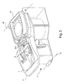
- Fig. 3 shows an exploded view, of selected components of the device 10 shown in Fig.1 with the housing 101 removed.
- arrangements are described for movement of a brew chamber lid and a reservoir lid 51, but aspects of the invention are not limited to the embodiments described, e.g., neither the brew chamber 1 nor the reservoir 5 need have a lid in some aspects of the invention.
- the device 10 likely would include other parts that are not shown here for purposes of clarity.
- the handle 3 is fixed to a lid carrier 42 that is pivotally mounted to a frame 6 at an axis 41.
- the frame 6 may form a skeleton of the device 10, supporting the housing 101 as well as other components of the device 10.
- the lid carrier 42 has mounted to it a brew chamber lid 12 and a reservoir lid 51 that cover an opening in a beverage cartridge receiver 11 and an access opening in the reservoir 5, respectively.
- the brew chamber lid 12 may be fixed relative to the lid carrier 42, and thus may move to open or close the brew chamber 1 with movement of the lid carrier 42.
- the reservoir lid 51 may be moveably mounted on the lid carrier 42, e.g., so that the lid 51 may pivot about the axis 41. Thus, the reservoir lid 51 may pivot or otherwise move relative to the container part of the reservoir 5 to expose the access opening of the reservoir 5.
- opening of the brew chamber 1 is initiated by depressing a lever 2, which releases a locking arrangement 21 that engages a portion 61 of the frame 6 to lock the lid carrier 42 in the closed position and prevent lifting of the handle 3.
- locking of the lid carrier 42 may be performed using other arrangements, or may not be provided at all.
- locking of the lid carrier 42 or otherwise resisting opening of the brew chamber 1 may help the device 10 resist the pressures developed in the brew chamber 1 during beverage formation.
- the locking arrangement 21 includes a first slider 21a that can move forward and back on the lid carrier 42 and is biased by a spring or other resilient member to move in the forward direction.
- depression of the lever 2 overcomes the bias of the spring or other element, and causes the first slider 21a to move rearwardly and disengage the portion 61 of the frame 6.
- locking of the lid carrier 42 may be accomplished in other ways, such as by a detent mechanism, other latch constructions, linkages, etc.
- the lid 51 is locked in place by a second slider 21b of the locking arrangement 21 that is slidably mounted on the lid carrier 42.
- the second slider 21b is biased, e.g., by a spring, to move rearwardly and engage tab portions 53 on the lid 51, thereby keeping the lid 51 in place relative to the lid carrier 42.
- the lid 51 is released and may be moved to expose the access opening of the reservoir 5.
- engagement of the slider 21b with a portion 62 of the frame 6 as the lid carrier 42 is moved downwardly to close the brew chamber 1 causes the slider 21b to move forwardly toward the handle 3 and unlock the lid 51.
- the lid 51 is spring biased to pivot upwardly and away from the lid carrier 42 so that upon release of the lid 51, the lid 51 moves abruptly to an open position.
- the lid 51 need not be spring biased, but may be moved by hand, by motor drive or other arrangement.
- the lid 51 need not necessarily pivot about the axis 41, but instead may pivot about any other suitably arranged axis, may slide side-to-side or forward-to-back, or move in any other way to exposed/cover the access opening.
- the lid carrier 42 is not required, and the brew chamber lid 12 and reservoir lid 51 may be separately mounted to the frame 6 or other member. Alternately, the lid carrier 42 may move in other ways, such as with a sliding motion, a non-pivoting up and down motion, etc.
- aspects of the invention are not limited in the way that the brew chamber is opened/closed and/or the way that the access opening to the reservoir is opened or covered to prevent access to the reservoir.
- the reservoir lid 51 may be arranged to pneumatically seal the reservoir 5 when the lid 51 is in a closed position relative to the access opening of the reservoir 5.
- the liquid in the reservoir 5 may be caused to flow to the brew chamber 1 by pressure in the reservoir 5, e.g., air pressure introduced by an air pump or other means.
- the lid 51 includes a silicone rubber seal 52 that engages with the container portion of the reservoir 5, but other sealing arrangements are possible, such as an interference or other close fit, other gasket arrangements, etc.
- the lid carrier 42 includes a pair of depending arms 43 that each have a pin that engage with corresponding slots 14 in the cartridge receiver 11. As the lid carrier 42 and arms 43 move upwardly, engagement of the arms 43 with the slots 14 causes the receiver 11 to tilt forward about an axis 13. It should be understood that the receiver 11 may be tilted forward in other ways, such as by hand, a motor driven mechanism, or other arrangement. Alternately, the receiver 11 may remain stationary.
- Figs. 4-8 show the arrangement of Figs. 2 and 3 in various states of operation.
- Fig. 4 shows an initial configuration with the brew chamber 1 closed and the reservoir lid 51 closed, i.e., a configuration in which a user might typically find the beverage forming device 10 after a beverage has just been made.
- the user may open the brew chamber 1, e.g., by depressing the lever 2, which causes the slider 21a to move rearwardly against a spring bias, as shown in Fig. 5 .
- Rearward movement of the slider 21a causes the slider 21a to disengage from the portion 61 of the frame 6, allowing the lid carrier 42 to be raised by lifting of the handle 3.
- the lid carrier 42 may be biased to move upwardly, e.g., under a spring or other bias, or may be arranged to require the user to support and lift the lid carrier 42.
- the cartridge receiver 11 With the lid carrier 42 fully lifted as shown in Fig. 6 , the cartridge receiver 11 is tilted forward and positioned to receive a cartridge for brewing a beverage.
- a detent or other arrangement may be employed to maintain the lid carrier 42 in a lifted condition, e.g., to help prevent inadvertent closing of the brew chamber 1.
- lifting of the lid carrier 42 and engagement of the arms 43 with the slots 14 in the receiver 11 causes the receiver 11 to tilt forward about the axis 13.
- the cartridge receiver 11 pivots forward about an axis 13 based on engagement of arms 43 with a slot 14 in the cartridge receiver 11 to allow for easier handling of the cartridge, the cartridge receiver 11 may be moved manually, may remain stationary, and/or may move in other ways.
- the reservoir lid 51 is opened from a closed position (in which the lid 51 seals the reservoir 5), but the reservoir lid 51 still covers the access opening to the reservoir receptacle so that a user may not pour water into the reservoir 5.
- the access opening is slightly opened, the access opening is not exposed.
- the handle 3 may be depressed as shown in Fig. 7 to close the brew chamber lid 12 and thus the brew chamber 1.
- the slider 21a may re-engage with the portion 61 of the frame 6 so as to lock the lid carrier 42 in a closed position.
- the reservoir lid 51 may travel with the lid carrier 42 until the brew chamber lid 12 is nearly closed or closed and the slider 21b engages with a portion 62 on the frame 6, which causes the slider 21b to disengage from the tab portions 53 on the reservoir lid 51.
- the reservoir lid 51 may pivot freely on the lid carrier 42, e.g., about the axis 41 to an open position shown in Fig. 7 to allow access to the reservoir 5.
- the reservoir lid 51 may have a spring bias that urges the lid 51 to move to the position shown in Fig. 7 .
- the lid 51 may move abruptly to the position shown in Fig. 7 . This may draw the user's attention to the fact that water should be provided in the reservoir 5 for brewing.
- the reservoir 5 is sized to receive only enough water for the preparation of one cup of beverage (e.g., 6, 8, 10 or 12 ounces), and the device 10 is operated to empty the reservoir 5 during each brew cycle.
- the reservoir 5 in this embodiment needs refilling after each completed brew cycle.
- This embodiment may be useful in certain applications, such as hotel use or other circumstances when it may not be desired to store water in the brewer.
- the reservoir 5 may have a larger capacity, or be provided water from a separate storage tank or a plumbed connection.
- the user may push the reservoir lid 51 down so that it locks in place on the lid carrier 42 (the tab portions 53 engage with the slider 21b - shown in Fig. 8 ) and pneumatically seals the reservoir 5 closed.
- a pneumatic seal it is meant that the lid 51 provides a suitable seal of the reservoir 5 to allow pneumatic delivery of water in the reservoir to the cartridge, as described in more detail below.
- the slider 21b and the frame portion 62 form a lid control mechanism that functions to lock the reservoir lid 51 in a position to block access to the access opening while the brew chamber lid 12 is open and unlocks the lid 51 to allow access to the access opening when the brew chamber lid 12 is moved toward the closed position.
- a lid control mechanism may include other components that provide the same or similar function.
- the lid control mechanism may include a solenoid-activated latch that is triggered to release the lid 51 from a locked position on the lid carrier 42 upon closure of a switch when the lid carrier 42 is lowered to close the brew chamber 1.
- the lid control mechanism may include a motor that is actuated to drive the lid 51 to move toward an open position in response to initiation of closure of the brew chamber 1, e.g., as sensed by a photodetector, switch or other detector.
- the lid control mechanism may be altered to function in a different way, e.g., to cause simultaneous and automatic opening of the reservoir lid 51 upon opening of the brew chamber lid 12.
- the slider 21b and the frame portion 62 may be arranged to unlock the lid 51 from the lid carrier 42 when the user lifts the handle 3 with the brew chamber lid 12 in the closed position.
- the slider 21a may engage with the lid 51 so as to lock the lid in a closed position with the brew chamber 1 closed, and release the reservoir lid 51 upon depression of the lever 2.
- Other arrangements are possible, such as a push button function whereby a user presses a push button, which causes the brew chamber lid 12 and the reservoir lid 51 to move toward respective open positions whether by motorized, manual, electromechanical or other means.
- Fig. 9 shows a schematic diagram of a beverage forming device 10 in accordance with aspects of the invention, e.g., the device 10 shown in Figs. 1-8 .
- the user may press a brew button (such the power button 91) to cause the brewer to start a brew cycle.
- initiation of a brew cycle may begin with heating of the water in the reservoir 5, and when the water is sufficiently heated, delivery of the water to the brew chamber may be initiated. Heating of the water may be done in any suitable way.
- a controller 9 may control the heater 94 to begin heating of the water in the reservoir 5, e.g., by an electrical resistance heater in or around the reservoir 5, a heater in the line 96 leading from the reservoir 5 to the brew chamber 1, or otherwise arranged to heat the water.
- a thermal cut off (TCO) switch 93 associated with the reservoir 5 may open and cause power to be cut off to the heater 94, e.g., the TCO switch 93 may be arranged in the power supply line to the heater 94.
- TCO thermal cut off
- the controller 9 may include a microprocessor for performing data processing functions, a memory for storing data and/or operating instructions, communication buses or other devices, software or other computer-executable instructions, a power supply or other power source such as a plug for mating with an electrical outlet, relays, mechanical linkages, user data input devices such as buttons, a touch screen or other, information display devices such as an LCD display, indicator lights or other, and/or other components for providing desired control functions
- the controller 9 may detect the opening of the TCO (such as by detecting a drop in voltage at the heater 94) and in response cause delivery of water to the brew chamber 1, e.g., control an air pump 92 to begin operation.
- the air pump 92 may deliver air under pressure to the reservoir 5 to cause the pressure in the reservoir 5 to rise, causing heated water to be forced from the reservoir 5 to the brew chamber 1 via a line 96.
- the reservoir 5 may have an outlet at or near the bottom of the reservoir 5 so that heated water is forced from the outlet and into the line 96 (which may include a check valve to help prevent backflow of fluid in the line 96).
- Heated water or other precursor liquid that is provided to the brew chamber may enter a beverage cartridge in the brew chamber 1 via an inlet needle that punctures the cartridge when the brew chamber lid 12 closes the brew chamber 1.
- the water may contact the beverage medium in the cartridge and a formed beverage may exit the cartridge, e.g., via an exit needle that punctures a bottom side of the cartridge.
- the air pump 92 may run for a specified period of time, e.g., 60 seconds, or otherwise controlled (e.g., by detecting a drop in pressure in the reservoir 5 signifying an absence of liquid) to empty the reservoir 5 of all water or other liquid.
- the timing of the air pump operation may be arranged so that mainly air is pumped at the end of the cycle, e.g., to help purge the cartridge of any remaining beverage, as well as to help dry the reservoir 5 and the line 96.
- the reservoir 5 may be vented to allow escape of steam or other pressurized gas during heating of the water, but not interfere with pneumatic delivery of water from the reservoir 5 to the brew chamber 1.
- an orifice 95 arranged in the connection between the air pump 92 and the reservoir 5 may be suitably arranged to properly vent the reservoir 5 during heating (e.g., to prevent substantial delivery of water from the reservoir 5 to the brew chamber 1 until the air pump 92 is operated), and be arranged so that pressurization of the reservoir 5 by the air pump 92 causes desired delivery of water to the brew chamber 1.
- the orifice has a diameter of approximately 0.012 inch.
- the brewer may include a cup or mug sensor 97 that detects whether a container is positioned to receive a beverage as it exits the brew chamber 1 and cartridge. If a container is not detected, the controller 9 may prevent the brewer from operating, e.g., may prevent water heating, air pump operation, etc. Also, if the cup sensor detects that the container is removed during a brew cycle (e.g., during water heating or delivery of heated water to the cartridge), the controller 9 may stop brewer operation (stop heating or water delivery.) The brew cycle may be resumed if the container is detected to be replaced.
- the cup sensor may take any suitable form, such as an LED and photodetector.
- the controller 9 may include a feature that powers up the device 10 upon detection that the brew chamber 1 has been opened.
- a user need not be required to turn the device 10 on when seeking to make a beverage, e.g., by pressing the power button 91, but instead may simply lift the handle 3 or otherwise open the brew chamber 1 and place a new cartridge in the brew chamber 1.
- the controller 5 may begin the brew cycle (e.g., water heating, followed by water delivery to the brew chamber).
- the controller 9 may include one or more sensors to detect opening/closing of the brew chamber 1 and/or the reservoir lid 51 to power up the device 10 and/or initiate a brew cycle.
- sensors may include a microswitch that is opened/closed upon movement of the lid carrier 42, the brew chamber lid 12, the reservoir lid 51, the lever 2 and/or other suitable components.
- Power up of the device 10 may be triggered, for example, by a switch detecting movement of the brew chamber lid 12 or lid carrier 42 from the closed position toward the open position, and/or by depression of the lever 2.
- a switch may provide a brew indication signal by detecting the closure of the reservoir lid 51.
- the reservoir lid switch may detect that both a new cartridge has been placed, as well as provision of water into the reservoir 5, allowing the controller 9 to initiate a brew cycle upon closure of the reservoir lid 51.
- the sensor(s) may alternately, or in addition, detect the presence of a cartridge in the brew chamber 1, water or other liquid in the reservoir 5 and/or other features for suitable control of the device 10.
- the device 10 may receive a brew indication from a user to start a brew cycle in a variety of different ways, e.g., by closing the reservoir lid 51, by pressing a power button 91 or other user input, by placing a cup or other receptacle under the brew chamber or otherwise to receive a beverage, and so on.
Abstract
Description
- This application claims the benefit of
U.S. Provisional Application 60/843,012, filed Sept. 7, 2006 - Some types of beverage forming devices, such as coffee brewers, use a cartridge containing a beverage medium, e.g., ground coffee, to form a beverage. In coffee brewers of this type, water is heated by the brewer and introduced into the cartridge. The water infuses with the coffee in the cartridge, and the beverage formed is removed from the cartridge for consumption. Many coffee brewers of this type commonly require a user to provide water to the machine that is used to form the beverage.
- The inventors have appreciated that in some applications, users of a beverage forming device, such as a coffee brewer, may need to be reminded of the need to provide water to the brewer. For example, with brewers used by hotel guests in their room, the guests may not be familiar with the brewer operation, and proper reminders regarding the need to provide water may help avoid user frustration or failure to properly operate the device. In other embodiments, it may be desirable to keep the brewer empty of water between uses. Again using the hotel brewer context as an example, it may be preferable to maintain the brewer empty of water between uses, e.g., because several hours or days may pass between uses. Requiring a user to provide fresh water at the time of use may help to provide a higher quality beverage.
- One aspect of the invention relates to a method of brewer operation, which may include placing a brew cartridge in the brewer, and then closing a brew chamber to at least partially enclose the cartridge. Closing of the brew chamber may automatically enable the providing of water or other beverage precursor liquid into a reservoir in the brewer, which is then used (heated or not) with the cartridge to form a beverage. For example, closing the brew chamber may cause a lid for a water reservoir to be fully opened or otherwise moved to allow access to an access opening of the reservoir, allowing a user to provide water into the reservoir. The reservoir lid may open with an abrupt action, causing attention to be drawn to the reservoir lid. In one embodiment, the lid may open with a spring action, e.g., to help further draw attention to the water reservoir and the need to provide water. Such a feature may be useful in certain embodiments, such as brewers arranged to form one cup of beverage at a time and thus requiring water to be provided for each brew cycle. In another embodiment, closure of the brew chamber may cause actuation of a baffle, pump, valve or other device to provide a suitable amount of water to a reservoir for beverage formation.
- In another aspect of the invention, a beverage formation device may include a brew chamber for receiving a beverage cartridge and have a lid that is movable between open and closed positions to open and close the brew chamber. The brew chamber may be adapted to substantially enclose a beverage cartridge with the lid in a closed position. A reservoir may hold a beverage precursor liquid, such as water, and have a lid that is movable to open and close an access opening through which precursor liquid is provided into the reservoir. A heater may heat the precursor liquid that is provided to the brew chamber, and a lid control mechanism may lock the reservoir lid in a position to block access to the access opening while the brew chamber lid is open, and unlock the lid to allow access to the access opening when the brew chamber lid is moved from the open position to the closed position.
- In another aspect of the invention, a brewer may be configured so that when a user opens a brew chamber, e.g., to place a cartridge in the brewer, a lid of a water reservoir is also opened simultaneously and automatically with opening of the brew chamber. After placement of the cartridge in the brew chamber and the brew chamber is closed, the lid of the water reservoir may remain open, e.g., to help remind a user to provide water to the brewer. The open reservoir lid may include a sound, sign display, or other indication to the user to provide water for the brew cycle , e.g., a visible marking, such as printed text "Add Water" to help guide the user's operation of the device.
- In another aspect of the invention, a method for operating a brewer includes providing a brew cartridge, providing water in a reservoir for beverage formation, closing a lid to close the access opening and pneumatically seal the reservoir, heating the water, and providing the water to the cartridge to form a beverage. Water may be provided into the reservoir by a user pouring the water through a reservoir access opening. The pneumatic seal may be provided by a silicone rubber gasket between the lid and reservoir body and/or any other suitable arrangement. Pneumatic sealing of the reservoir may allow the water in the reservoir to be expelled from the reservoir for flow to the brew chamber by introducing air pressure into the reservoir, e.g., by an air pump. The reservoir may be vented during heating of the water, e.g., to allow steam or other gases to escape, and during pressurization of the reservoir and delivery of the brew water. However, the venting arrangement may be constructed to allow a suitably small amount of gas to escape so as to allow successful delivery of the brew water to the brew chamber. As a result, heating of the water and the attendant steam creation or other pressure generation, may not cause delivery of water to the cartridge. Instead, such pressure may be vented and the water delivered to the cartridge when appropriate. Such an arrangement may avoid the need for providing controlled venting, e.g., by way of a controllable valve, yet still permit pressurized delivery of water from the reservoir.
- In another aspect of the invention, a beverage formation device may include a brew chamber for receiving a beverage cartridge and have a lid that is movable between open and closed positions to open and close the brew chamber. The brew chamber may be adapted to substantially enclose a beverage cartridge with the lid in a closed position. A reservoir may hold a beverage precursor liquid and have a lid that is movable to open and close an access opening through which precursor liquid is provided into the reservoir. The lid may be adapted to pneumatically seal the reservoir access opening in a closed position, and thereby pneumatically seal the reservoir so that liquid in the reservoir may be delivered by pressurizing the reservoir. A heater may heat the precursor liquid that is provided to the brew chamber, e.g., by way of a heater in the reservoir.
- In another aspect of the invention, a method for operating a brewer includes providing a brew cartridge, providing water in a reservoir, providing a brew indication to begin a brewing cycle, heating the water, detecting when the water is heated to a desired temperature, and then providing the water to the cartridge to form a beverage based on the detected temperature. In one embodiment, detection of the water temperature is performed by a temperature cut off switch (TCO) which is normally closed to provide power to a water heater, but opens when the water reaches a predetermined temperature. Opening of the TCO may cause the brewer to deliver the heated water to the cartridge. For example, the brewer may include an air pump that pneumatically pressurizes the water reservoir in response to opening of the TCO switch, thereby forcing the heated water to the cartridge. Such an arrangement may provide for a simplified control mechanism.
- In another aspect of the invention, a method for forming a beverage includes providing a brew indication to cause a brewer to begin a brew cycle, delivering power to a heater to heat precursor liquid in a reservoir of the brewer, detecting the temperature of the precursor liquid during heating, interrupting power to the heater based on detecting that the precursor liquid is heated to a desired temperature, and delivering the precursor liquid from the reservoir based on interrupting power to the heater. Thus, control of delivery of water from the reservoir may be made based on power interruption to the heater, thereby ensuring that the heater is not operating while water is being delivered from the reservoir. This feature may help prevent damage to the heater or other components that might be caused by operating the heater without having sufficient water present to receive the heat generated, especially in devices that empty the reservoir of liquid during each brew cycle.
- In another aspect of the invention, a beverage forming machine includes a brew chamber for receiving a brew cartridge, a reservoir for receiving precursor liquid for use in forming a beverage, and a brew indication switch for receiving an indication from a user to begin a brewing cycle. The brew indication switch may take any suitable form, such as a power button that a user may press to initiate a brew cycle, a switch that detects closure of a lid for the reservoir, a cup sensor that detects the presence of a cup or other vessel to receive a beverage, etc. The machine may also include a heater for heating precursor liquid in the reservoir, a detector for detecting a desired temperature of precursor liquid in the reservoir, an air pump for providing pressurized air to the reservoir, and a controller constructed and arranged to control operation of the heater and the air pump. The controller may be adapted to control the heater to heat the precursor liquid and cause the air pump to deliver pressurized air to the reservoir when the detector detects that the precursor liquid is at the desired temperature.
- These and other aspects of the invention will be apparent from the following description and claims.
- Aspects of the invention are described with reference to the following drawings in which like numerals reference like elements, and wherein:
-
Fig. 1 is a perspective view of a beverage formation device in accordance with aspects of the invention; -
Fig. 2 is a perspective view of selected components of the beverage formation device ofFig. 1 ; -
Fig. 3 is an exploded view of the portion of the beverage formation device shown inFig. 2 ; -
Figs. 4-8 show the portion of the of the beverage formation device shown inFig. 2 in various states of opening and closing operations; and -
Fig. 9 is a schematic block diagram of a beverage formation device in accordance with aspects of the invention. - Various aspects of the invention are described below and/or shown in the drawings. These aspects of the invention may be used alone and/or in any suitable combination with each other. Aspects of the invention are not limited in any way by the illustrative embodiments shown and described herein.
- As used herein, a "cartridge" may take any suitable form, such as a pod (e.g., opposed layers of filter paper encapsulating a beverage medium), capsule, sachet or any other arrangement. The cartridge may be impervious to air and/or liquid, or may allow water and/or air to pass into the cartridge. The cartridge may include a beverage medium, such as tea, ground coffee, powdered milk, a drink mix, and/or any other suitable material for forming a beverage. The cartridge may include a filter or other arrangement to help prevent some portions of the beverage medium from being provided with the formed beverage, such as a coffee drink, tea, hot chocolate, etc. To "brew" a beverage includes infusion, mixing, dissolving, steeping or otherwise forming a drinkable substance using water or other beverage precursor (e.g., flavored or otherwise treated water, or other liquid) with a beverage medium. Also, reference to "water" herein is to any suitable water formulation, e.g., filtered, deionized, softened, etc., as well as any other suitable precursor liquid used to form a beverage, such as sweetened or flavored water, milk, etc.
-
Fig. 1 shows abeverage forming device 10 that incorporates various aspects of the invention. This illustrative embodiment includes ahousing 101 that encloses various parts of thedevice 10 and supports several external features, such as apower button 91, a cup sensor 97 (e.g., a photosensor) and/or other optional features. Abrew chamber 1 may be opened, e.g., by lifting ahandle 3, so that a beverage cartridge may be inserted into thebrew chamber 1 for forming a beverage. In this regard, thedevice 10 may operate, for example, as shown inU.S. Patent 7,165,488 , which is hereby incorporated by reference. That is, lifting thehandle 3 may cause a brew chamber lid (not shown inFig. 1 ) to be raised so that a cartridge receiver may tilt forward to receive a beverage cartridge. Of course, it should be understood that thebrew chamber 1 may be opened in other ways, such as by push button actuation of a motor-driven mechanism, manual opening of a drawer that slides outwardly to receive a cartridge, and so on. - In one aspect of the invention, the
device 10 may automatically enable provision of water or other precursor liquid used to form a beverage into a reservoir 5 (e.g., used for water heating) in response to closing of thebrew chamber 1. For example, a user may lift thehandle 3 or otherwise cause thebrew chamber 1 to open. After placing a fresh cartridge in thebrew chamber 1, the user may cause thebrew chamber 1 to close, e.g., by pressing down on thehandle 3, pushing a control button that actuates a motor drive to close thebrew chamber 1, etc. Upon movement of the brew chamber toward the closed position, alid 51 of thereservoir 5 may open, allowing a user to access to thereservoir 5. With access to thereservoir 5, a user may pour water or other liquid into thereservoir 5 through an access opening exposed by theopen lid 51. Of course, provision of water or other liquid to thereservoir 5 may occur in other ways, and a user need not provide the liquid into thereservoir 5. For example, liquid may be provided in response to brew chamber closing by opening of a valve in a water supply line that feeds thereservoir 5. The water supply line may run from a storage tank on thedevice 10 or from a plumbed connection to a domestic water supply. In such embodiments, alid 51 for thereservoir 5 need not be provided since a user need not have access to thereservoir 5. However, in this embodiment, thereservoir 5 receives water or other liquid by a user pouring the liquid through an access opening exposed by opening of thereservoir lid 51. In accordance with this aspect of the invention, thedevice 10 may be effectively empty of water between uses, and have fresh water provided to the brewer in response to initiation of closure of thebrew chamber 1, which may signify a user's desire to form a beverage. - In another aspect of the invention, a
lid 51 of areservoir 5 may open simultaneously and automatically with opening of thebrew chamber 1. For example, thelid 51 of thereservoir 5 may pivot upwardly to expose an access opening for thereservoir 5 when the user takes action to open thebrew chamber 1, thereby allowing a user to pour water into thereservoir 5. Simultaneous and automatic opening of thebrew chamber 1 and thereservoir 5 may be controlled by a lid control mechanism, e.g., that unlatches thereservoir lid 51 from a locked closed position allowing thelid 51 to open under a spring bias in response to lifting of thehandle 3 and opening of thebrew chamber 1. Other arrangements for the lid control mechanism are possible, such as a motor-driven linkage that operates to open thelid 51 and thebrew chamber 1 in response to a user's press of a button, mechanical or electromechanical latching devices that unlatch thebrew chamber 1 andlid 51 allowing the brew chamber andlid 51 to open under a spring bias, and others. - To further illustrate these and other aspects of the invention,
Fig. 2 shows a schematic view, andFig. 3 shows an exploded view, of selected components of thedevice 10 shown inFig.1 with thehousing 101 removed. Reference is made toFigs. 2 and3 to illustrate aspects of the invention, but no limitation on such aspects of the invention is intended. For example, arrangements are described for movement of a brew chamber lid and areservoir lid 51, but aspects of the invention are not limited to the embodiments described, e.g., neither thebrew chamber 1 nor thereservoir 5 need have a lid in some aspects of the invention. Also, it should be understood that thedevice 10 likely would include other parts that are not shown here for purposes of clarity. - In the illustrative embodiment shown, the
handle 3 is fixed to alid carrier 42 that is pivotally mounted to aframe 6 at anaxis 41. Theframe 6 may form a skeleton of thedevice 10, supporting thehousing 101 as well as other components of thedevice 10. Thelid carrier 42 has mounted to it abrew chamber lid 12 and areservoir lid 51 that cover an opening in abeverage cartridge receiver 11 and an access opening in thereservoir 5, respectively. Thebrew chamber lid 12 may be fixed relative to thelid carrier 42, and thus may move to open or close thebrew chamber 1 with movement of thelid carrier 42. Thereservoir lid 51 may be moveably mounted on thelid carrier 42, e.g., so that thelid 51 may pivot about theaxis 41. Thus, thereservoir lid 51 may pivot or otherwise move relative to the container part of thereservoir 5 to expose the access opening of thereservoir 5. - In this illustrative embodiment, opening of the
brew chamber 1 is initiated by depressing alever 2, which releases a locking arrangement 21 that engages aportion 61 of theframe 6 to lock thelid carrier 42 in the closed position and prevent lifting of thehandle 3. However, such locking of thelid carrier 42 may be performed using other arrangements, or may not be provided at all. In some cases, locking of thelid carrier 42 or otherwise resisting opening of thebrew chamber 1 may help thedevice 10 resist the pressures developed in thebrew chamber 1 during beverage formation. In this embodiment, the locking arrangement 21 includes afirst slider 21a that can move forward and back on thelid carrier 42 and is biased by a spring or other resilient member to move in the forward direction. Thus, depression of thelever 2 overcomes the bias of the spring or other element, and causes thefirst slider 21a to move rearwardly and disengage theportion 61 of theframe 6. Of course, it should be understood that locking of thelid carrier 42 may be accomplished in other ways, such as by a detent mechanism, other latch constructions, linkages, etc. - Lifting of the
handle 3 pivots thelid carrier 42 about theaxis 41 to expose the opening in thecartridge receiver 11 and partially lift thereservoir lid 51 with respect to the access opening in thereservoir 5. However, with thereservoir lid 51 locked in place relative to thelid carrier 42, the access opening is not exposed to allow liquid to be provided into thereservoir 5 even with thelid carrier 42 fully raised. Thelid 51 is locked in place by asecond slider 21b of the locking arrangement 21 that is slidably mounted on thelid carrier 42. Thesecond slider 21b is biased, e.g., by a spring, to move rearwardly and engagetab portions 53 on thelid 51, thereby keeping thelid 51 in place relative to thelid carrier 42. However, with forward movement of theslider 21b, thelid 51 is released and may be moved to expose the access opening of thereservoir 5. As discussed in more detail below, engagement of theslider 21b with aportion 62 of theframe 6 as thelid carrier 42 is moved downwardly to close thebrew chamber 1 causes theslider 21b to move forwardly toward thehandle 3 and unlock thelid 51. In this embodiment, thelid 51 is spring biased to pivot upwardly and away from thelid carrier 42 so that upon release of thelid 51, thelid 51 moves abruptly to an open position. In other embodiments, thelid 51 need not be spring biased, but may be moved by hand, by motor drive or other arrangement. Also, thelid 51 need not necessarily pivot about theaxis 41, but instead may pivot about any other suitably arranged axis, may slide side-to-side or forward-to-back, or move in any other way to exposed/cover the access opening. Likewise, thelid carrier 42 is not required, and thebrew chamber lid 12 andreservoir lid 51 may be separately mounted to theframe 6 or other member. Alternately, thelid carrier 42 may move in other ways, such as with a sliding motion, a non-pivoting up and down motion, etc. In short, aspects of the invention are not limited in the way that the brew chamber is opened/closed and/or the way that the access opening to the reservoir is opened or covered to prevent access to the reservoir. - In accordance with an aspect of the invention, the
reservoir lid 51 may be arranged to pneumatically seal thereservoir 5 when thelid 51 is in a closed position relative to the access opening of thereservoir 5. By pneumatically sealing thereservoir 5, the liquid in thereservoir 5 may be caused to flow to thebrew chamber 1 by pressure in thereservoir 5, e.g., air pressure introduced by an air pump or other means. In this embodiment, thelid 51 includes asilicone rubber seal 52 that engages with the container portion of thereservoir 5, but other sealing arrangements are possible, such as an interference or other close fit, other gasket arrangements, etc. - As also described in more detail below, in this embodiment, the
lid carrier 42 includes a pair of dependingarms 43 that each have a pin that engage withcorresponding slots 14 in thecartridge receiver 11. As thelid carrier 42 andarms 43 move upwardly, engagement of thearms 43 with theslots 14 causes thereceiver 11 to tilt forward about anaxis 13. It should be understood that thereceiver 11 may be tilted forward in other ways, such as by hand, a motor driven mechanism, or other arrangement. Alternately, thereceiver 11 may remain stationary. -
Figs. 4-8 show the arrangement ofFigs. 2 and3 in various states of operation.Fig. 4 shows an initial configuration with thebrew chamber 1 closed and thereservoir lid 51 closed, i.e., a configuration in which a user might typically find thebeverage forming device 10 after a beverage has just been made. To start the process for forming a new beverage, the user may open thebrew chamber 1, e.g., by depressing thelever 2, which causes theslider 21a to move rearwardly against a spring bias, as shown inFig. 5 . Rearward movement of theslider 21a causes theslider 21a to disengage from theportion 61 of theframe 6, allowing thelid carrier 42 to be raised by lifting of thehandle 3. Thelid carrier 42 may be biased to move upwardly, e.g., under a spring or other bias, or may be arranged to require the user to support and lift thelid carrier 42. - With the
lid carrier 42 fully lifted as shown inFig. 6 , thecartridge receiver 11 is tilted forward and positioned to receive a cartridge for brewing a beverage. A detent or other arrangement may be employed to maintain thelid carrier 42 in a lifted condition, e.g., to help prevent inadvertent closing of thebrew chamber 1. As mentioned above, lifting of thelid carrier 42 and engagement of thearms 43 with theslots 14 in thereceiver 11 causes thereceiver 11 to tilt forward about theaxis 13. Although in this embodiment thecartridge receiver 11 pivots forward about anaxis 13 based on engagement ofarms 43 with aslot 14 in thecartridge receiver 11 to allow for easier handling of the cartridge, thecartridge receiver 11 may be moved manually, may remain stationary, and/or may move in other ways. In the condition shown inFig. 6 , thereservoir lid 51 is opened from a closed position (in which thelid 51 seals the reservoir 5), but thereservoir lid 51 still covers the access opening to the reservoir receptacle so that a user may not pour water into thereservoir 5. Thus, although the access opening is slightly opened, the access opening is not exposed. - With a cartridge (not shown) placed in the cartridge receiver 11 (and a spent cartridge removed from the
receiver 11 if necessary), thehandle 3 may be depressed as shown inFig. 7 to close thebrew chamber lid 12 and thus thebrew chamber 1. When thebrew chamber 1 is fully closed, theslider 21a may re-engage with theportion 61 of theframe 6 so as to lock thelid carrier 42 in a closed position. Thereservoir lid 51 may travel with thelid carrier 42 until thebrew chamber lid 12 is nearly closed or closed and theslider 21b engages with aportion 62 on theframe 6, which causes theslider 21b to disengage from thetab portions 53 on thereservoir lid 51. This allows thereservoir lid 51 to pivot freely on thelid carrier 42, e.g., about theaxis 41 to an open position shown inFig. 7 to allow access to thereservoir 5. Thereservoir lid 51 may have a spring bias that urges thelid 51 to move to the position shown inFig. 7 . Thus, when theslider 21b disengages from thelid 51, thelid 51 may move abruptly to the position shown inFig. 7 . This may draw the user's attention to the fact that water should be provided in thereservoir 5 for brewing. - In this embodiment, the
reservoir 5 is sized to receive only enough water for the preparation of one cup of beverage (e.g., 6, 8, 10 or 12 ounces), and thedevice 10 is operated to empty thereservoir 5 during each brew cycle. Thus, thereservoir 5 in this embodiment needs refilling after each completed brew cycle. This embodiment may be useful in certain applications, such as hotel use or other circumstances when it may not be desired to store water in the brewer. Of course, in other embodiments, thereservoir 5 may have a larger capacity, or be provided water from a separate storage tank or a plumbed connection. After water is provided in thereservoir 5, the user may push thereservoir lid 51 down so that it locks in place on the lid carrier 42 (thetab portions 53 engage with theslider 21b - shown inFig. 8 ) and pneumatically seals thereservoir 5 closed. By a pneumatic seal, it is meant that thelid 51 provides a suitable seal of thereservoir 5 to allow pneumatic delivery of water in the reservoir to the cartridge, as described in more detail below. - In this embodiment, the
slider 21b and theframe portion 62 form a lid control mechanism that functions to lock thereservoir lid 51 in a position to block access to the access opening while thebrew chamber lid 12 is open and unlocks thelid 51 to allow access to the access opening when thebrew chamber lid 12 is moved toward the closed position. However, it should be understood that a lid control mechanism may include other components that provide the same or similar function. For example, the lid control mechanism may include a solenoid-activated latch that is triggered to release thelid 51 from a locked position on thelid carrier 42 upon closure of a switch when thelid carrier 42 is lowered to close thebrew chamber 1. In another embodiment, the lid control mechanism may include a motor that is actuated to drive thelid 51 to move toward an open position in response to initiation of closure of thebrew chamber 1, e.g., as sensed by a photodetector, switch or other detector. In accordance with another aspect of the invention, the lid control mechanism may be altered to function in a different way, e.g., to cause simultaneous and automatic opening of thereservoir lid 51 upon opening of thebrew chamber lid 12. For example, theslider 21b and theframe portion 62 may be arranged to unlock thelid 51 from thelid carrier 42 when the user lifts thehandle 3 with thebrew chamber lid 12 in the closed position. Alternately, theslider 21a may engage with thelid 51 so as to lock the lid in a closed position with thebrew chamber 1 closed, and release thereservoir lid 51 upon depression of thelever 2. Other arrangements are possible, such as a push button function whereby a user presses a push button, which causes thebrew chamber lid 12 and thereservoir lid 51 to move toward respective open positions whether by motorized, manual, electromechanical or other means. -
Fig. 9 shows a schematic diagram of abeverage forming device 10 in accordance with aspects of the invention, e.g., thedevice 10 shown inFigs. 1-8 . With a fresh cartridge provided in thebrew chamber 1 and water in thereservoir 5, the user may press a brew button (such the power button 91) to cause the brewer to start a brew cycle. In accordance with one aspect of the invention, initiation of a brew cycle may begin with heating of the water in thereservoir 5, and when the water is sufficiently heated, delivery of the water to the brew chamber may be initiated. Heating of the water may be done in any suitable way. For example, acontroller 9 may control theheater 94 to begin heating of the water in thereservoir 5, e.g., by an electrical resistance heater in or around thereservoir 5, a heater in theline 96 leading from thereservoir 5 to thebrew chamber 1, or otherwise arranged to heat the water. Once the water is heated to a desired temperature, a thermal cut off (TCO) switch 93 associated with thereservoir 5 may open and cause power to be cut off to theheater 94, e.g., theTCO switch 93 may be arranged in the power supply line to theheater 94. (In some embodiments, sufficient heating of the water may be sensed in other ways, such as by a thermocouple, or other sensor.) In accordance with an aspect of the invention, the controller 9 (e.g., which may include a microprocessor for performing data processing functions, a memory for storing data and/or operating instructions, communication buses or other devices, software or other computer-executable instructions, a power supply or other power source such as a plug for mating with an electrical outlet, relays, mechanical linkages, user data input devices such as buttons, a touch screen or other, information display devices such as an LCD display, indicator lights or other, and/or other components for providing desired control functions) may detect the opening of the TCO (such as by detecting a drop in voltage at the heater 94) and in response cause delivery of water to thebrew chamber 1, e.g., control anair pump 92 to begin operation. Theair pump 92 may deliver air under pressure to thereservoir 5 to cause the pressure in thereservoir 5 to rise, causing heated water to be forced from thereservoir 5 to thebrew chamber 1 via aline 96. Thereservoir 5 may have an outlet at or near the bottom of thereservoir 5 so that heated water is forced from the outlet and into the line 96 (which may include a check valve to help prevent backflow of fluid in the line 96). Heated water or other precursor liquid that is provided to the brew chamber may enter a beverage cartridge in thebrew chamber 1 via an inlet needle that punctures the cartridge when thebrew chamber lid 12 closes thebrew chamber 1. The water may contact the beverage medium in the cartridge and a formed beverage may exit the cartridge, e.g., via an exit needle that punctures a bottom side of the cartridge. Theair pump 92 may run for a specified period of time, e.g., 60 seconds, or otherwise controlled (e.g., by detecting a drop in pressure in thereservoir 5 signifying an absence of liquid) to empty thereservoir 5 of all water or other liquid. The timing of the air pump operation may be arranged so that mainly air is pumped at the end of the cycle, e.g., to help purge the cartridge of any remaining beverage, as well as to help dry thereservoir 5 and theline 96. - As described above and in accordance with one aspect of the invention, the
reservoir 5 may be vented to allow escape of steam or other pressurized gas during heating of the water, but not interfere with pneumatic delivery of water from thereservoir 5 to thebrew chamber 1. For example, anorifice 95 arranged in the connection between theair pump 92 and thereservoir 5 may be suitably arranged to properly vent thereservoir 5 during heating (e.g., to prevent substantial delivery of water from thereservoir 5 to thebrew chamber 1 until theair pump 92 is operated), and be arranged so that pressurization of thereservoir 5 by theair pump 92 causes desired delivery of water to thebrew chamber 1. In one illustrative embodiment, the orifice has a diameter of approximately 0.012 inch. - In one embodiment, the brewer may include a cup or
mug sensor 97 that detects whether a container is positioned to receive a beverage as it exits thebrew chamber 1 and cartridge. If a container is not detected, thecontroller 9 may prevent the brewer from operating, e.g., may prevent water heating, air pump operation, etc. Also, if the cup sensor detects that the container is removed during a brew cycle (e.g., during water heating or delivery of heated water to the cartridge), thecontroller 9 may stop brewer operation (stop heating or water delivery.) The brew cycle may be resumed if the container is detected to be replaced. The cup sensor may take any suitable form, such as an LED and photodetector. - In another aspect of the invention, the
controller 9 may include a feature that powers up thedevice 10 upon detection that thebrew chamber 1 has been opened. In accordance with this aspect of the invention, a user need not be required to turn thedevice 10 on when seeking to make a beverage, e.g., by pressing thepower button 91, but instead may simply lift thehandle 3 or otherwise open thebrew chamber 1 and place a new cartridge in thebrew chamber 1. Upon closing of thebrew chamber 1 and the reservoir lid 51 (indicating that a new cartridge has been placed and water has been provided in the reservoir 5), thecontroller 5 may begin the brew cycle (e.g., water heating, followed by water delivery to the brew chamber). Thecontroller 9 may include one or more sensors to detect opening/closing of thebrew chamber 1 and/or thereservoir lid 51 to power up thedevice 10 and/or initiate a brew cycle. Such sensors may include a microswitch that is opened/closed upon movement of thelid carrier 42, thebrew chamber lid 12, thereservoir lid 51, thelever 2 and/or other suitable components. Power up of thedevice 10 may be triggered, for example, by a switch detecting movement of thebrew chamber lid 12 orlid carrier 42 from the closed position toward the open position, and/or by depression of thelever 2. In one embodiment, a switch may provide a brew indication signal by detecting the closure of thereservoir lid 51. Since in the embodiment described above thereservoir lid 51 cannot be fully closed unless thebrew chamber 1 is closed, the reservoir lid switch may detect that both a new cartridge has been placed, as well as provision of water into thereservoir 5, allowing thecontroller 9 to initiate a brew cycle upon closure of thereservoir lid 51. The sensor(s) may alternately, or in addition, detect the presence of a cartridge in thebrew chamber 1, water or other liquid in thereservoir 5 and/or other features for suitable control of thedevice 10. Accordingly, thedevice 10 may receive a brew indication from a user to start a brew cycle in a variety of different ways, e.g., by closing thereservoir lid 51, by pressing apower button 91 or other user input, by placing a cup or other receptacle under the brew chamber or otherwise to receive a beverage, and so on. - The above and other aspects of the invention will be appreciated from the detailed description and claims. It should be understood that although aspects of the invention have been described with reference to illustrative embodiments, aspects of the invention are not limited to the embodiments described. Also, aspects of the invention may be used alone, or in any suitable combination with other aspects of the invention.
Claims (15)
- A method for forming a beverage, comprising:providing a brew indication to cause a brewer to begin a brew cycle;delivering power to a heater to heat precursor liquid in a reservoir of the brewer; detecting the temperature of the precursor liquid during heating;interrupting power to the heater based on detecting that the precursor liquid is heated to a desired temperature; anddelivering the precursor liquid from the reservoir based on interrupting power to the heater.
- A method according to claim 1, wherein the step of delivering the precursor liquid comprises pneumatically pressurizing the reservoir to force precursor liquid from the reservoir.
- A method according to claim 1 or 2, wherein the step of detecting the temperature comprises using a thermal cut off (TCO) switch that opens when the precursor liquid is heated to the desired temperature.
- A method according to claim 3, wherein the step of delivering the precursor liquid comprises starting operation of an air pump to pressurize the reservoir in response to the TCO switch opening.
- A method according to any preceding claim, wherein the brewer includes:a brew chamber for receiving a beverage cartridge and having a lid that is movable between open and closed positions to open and close the brew chamber, the brew chamber adapted to substantially enclose a beverage cartridge with the lid in a closed position; andthe reservoir includes a lid that is movable to open and close an access opening through which precursor liquid is provided into the reservoir.
- A method according to any of claims 1 to 4, further comprising introducing the precursor liquid from the reservoir into a beverage cartridge to form a beverage.
- A method according to any of claims 1 to 4, wherein the brew indication is provided by closing a lid of the reservoir.
- A method according to any preceding claim, wherein the step of delivering the precursor liquid comprises emptying the reservoir of precursor liquid.
- A beverage forming machine comprising:a brew chamber for receiving a brew cartridge;a reservoir for receiving precursor liquid for use in forming a beverage;a brew indication switch for receiving an indication from a user to begin a brewing cycle;a heater for heating precursor liquid in the reservoir;a detector for detecting a desired temperature of precursor liquid in the reservoir;an air pump for providing pressurized air to the reservoir; anda controller constructed and arranged to control operation of the heater and the air pump;wherein the controller is adapted to control the heater to heat the precursor liquid and cause the air pump to deliver pressurized air to the reservoir when the detector detects that the precursor liquid is at the desired temperature.
- A machine according to claim 9, wherein the detector is a thermal cut off (TCO) switch that interrupts power to the heater when the precursor liquid is heated to the desired temperature.
- A machine according to claim 10, wherein the controller causes the air pump to deliver pressurized air when the TCO interrupts power to the heater.
- A machine according to any of claim 9 to 11, wherein:the brew chamber has a lid that is movable between open and closed positions to open and close the brew chamber and the brew chamber is adapted to substantially enclose the beverage cartridge with the lid in a closed position; andthe reservoir includes a lid that is movable to open and close an access opening through which precursor liquid is provided into the reservoir.
- A machine according to claim 12, wherein the reservoir lid is adapted to pneumatically seal the reservoir access opening in a closed position.
- A machine according to any of claims 9 to 11, wherein the brew indication switch is activated by closing a lid of the reservoir.
- A machine according to any of claims 9 to 14, wherein the controller controls the air pump to empty the reservoir of precursor liquid when the detector detects that the precursor liquid is at the desired temperature.
Applications Claiming Priority (2)
| Application Number | Priority Date | Filing Date | Title |
|---|---|---|---|
| US84301206P | 2006-09-07 | 2006-09-07 | |
| EP20070837907 EP2059156B1 (en) | 2006-09-07 | 2007-09-07 | Method and apparatus for beverage formation |
Related Parent Applications (2)
| Application Number | Title | Priority Date | Filing Date |
|---|---|---|---|
| EP07837907.0 Division | 2007-09-07 | ||
| EP20070837907 Division EP2059156B1 (en) | 2006-09-07 | 2007-09-07 | Method and apparatus for beverage formation |
Publications (2)
| Publication Number | Publication Date |
|---|---|
| EP2189086A1 true EP2189086A1 (en) | 2010-05-26 |
| EP2189086B1 EP2189086B1 (en) | 2015-11-11 |
Family
ID=39157874
Family Applications (3)
| Application Number | Title | Priority Date | Filing Date |
|---|---|---|---|
| EP09165407.9A Active EP2119384B1 (en) | 2006-09-07 | 2007-09-07 | Method and apparatus for beverage formation |
| EP20070837907 Active EP2059156B1 (en) | 2006-09-07 | 2007-09-07 | Method and apparatus for beverage formation |
| EP09173135.6A Active EP2189086B1 (en) | 2006-09-07 | 2007-09-07 | Method and Apparatus for Beverage Formation |
Family Applications Before (2)
| Application Number | Title | Priority Date | Filing Date |
|---|---|---|---|
| EP09165407.9A Active EP2119384B1 (en) | 2006-09-07 | 2007-09-07 | Method and apparatus for beverage formation |
| EP20070837907 Active EP2059156B1 (en) | 2006-09-07 | 2007-09-07 | Method and apparatus for beverage formation |
Country Status (12)
| Country | Link |
|---|---|
| US (4) | US8573114B2 (en) |
| EP (3) | EP2119384B1 (en) |
| JP (3) | JP4956718B2 (en) |
| KR (3) | KR101067540B1 (en) |
| CN (3) | CN101534687B (en) |
| AT (1) | ATE464821T1 (en) |
| AU (3) | AU2007292922B2 (en) |
| CA (3) | CA2689795C (en) |
| DE (1) | DE602007006027D1 (en) |
| HK (3) | HK1135581A1 (en) |
| NZ (3) | NZ576528A (en) |
| WO (1) | WO2008030577A2 (en) |
Cited By (2)
| Publication number | Priority date | Publication date | Assignee | Title |
|---|---|---|---|---|
| CN104780817A (en) * | 2012-11-09 | 2015-07-15 | 豪威株式会社 | Coffee capsule mounting and removal structure |
| WO2016133858A1 (en) * | 2015-02-17 | 2016-08-25 | Keurig Green Mountain, Inc. | Cartridge holder for beverage machine |
Families Citing this family (146)
| Publication number | Priority date | Publication date | Assignee | Title |
|---|---|---|---|---|
| US20060289253A1 (en) * | 2005-06-23 | 2006-12-28 | Kelsey-Hayes Company | Monoblock caliper housing for a disc brake assembly |
| US7081263B2 (en) | 2002-05-01 | 2006-07-25 | Courtesy Products, Llc | Disposable brew basket for electric coffee maker |
| US7770512B2 (en) * | 2002-05-01 | 2010-08-10 | Courtesy Products, Llc | Disposable brew basket for electric coffee maker |
| KR101067540B1 (en) | 2006-09-07 | 2011-09-27 | 큐릭, 인코포레이티드 | Method and apparatus for beverage formation |
| US20130243919A1 (en) * | 2007-02-16 | 2013-09-19 | James P. Shrader | Espresso Maker and Method |
| US20110020508A1 (en) | 2007-04-05 | 2011-01-27 | Rising Phoenix Co. | Select Serving and Flavored Sparkling Beverage Maker |
| WO2008124851A1 (en) * | 2007-04-05 | 2008-10-16 | Carl Santoiemmo | Select serving and flavored sparkling beverage maker |
| US8677888B2 (en) * | 2007-04-05 | 2014-03-25 | Primo Products, LLC | Select serving and flavored sparkling beverage maker |
| GB2449421B (en) * | 2007-05-18 | 2009-09-09 | Kraft Foods R & D Inc | Improvements in or relating to beverage preparation machines |
| ES2359997T3 (en) * | 2007-12-18 | 2011-05-30 | Nestec S.A. | DEVICE FOR PREPARING A DRINK WITH A REMOVABLE INJECTION ELEMENT. |
| CA2723189A1 (en) * | 2008-04-30 | 2009-11-05 | Bunn-O-Matic Corporation | Brewer including substance removal assembly |
| EP2158828A1 (en) | 2008-08-25 | 2010-03-03 | Koninklijke Philips Electronics N.V. | Device for frothing milk, comprising means for preventing blockage of an air restriction by milk residue |
| CA2836424C (en) | 2008-08-29 | 2016-12-20 | Pepsico, Inc. | Post-mix beverage system |
| US9272827B2 (en) * | 2008-08-29 | 2016-03-01 | Pepsico, Inc. | Post-mix beverage system |
| IT1393999B1 (en) * | 2009-04-01 | 2012-05-17 | Rancilio Macchine Caffe | MACHINE FOR THE PREPARATION OF INFUSES, ESPRESSO IN PARTICULAR COFFEE, DISPENSER GROUP AND METHOD OF REALIZING THE SAME |
| KR101609390B1 (en) * | 2009-05-11 | 2016-04-05 | 엘지전자 주식회사 | Cooker |
| PL2442695T3 (en) | 2009-06-17 | 2015-08-31 | Douwe Egberts Bv | Capsule and system for preparing a beverage comprising soluble substance |
| ES2478843T3 (en) | 2009-06-17 | 2014-07-23 | Koninklijke Douwe Egberts B.V. | Method, system and receptacle for preparing a drink |
| BRPI0925097B1 (en) | 2009-06-17 | 2019-07-16 | Koninklijke Douwe Egberts B.V. | CAPSULE, SYSTEM AND METHOD FOR PREPARING A PRE-DETERMINED DRINKING QUANTITY |
| KR20120027532A (en) | 2009-06-17 | 2012-03-21 | 사라 리/디이 비.브이. | System, method and capsule for preparing a beverage |
| PL2367740T3 (en) | 2009-06-17 | 2014-10-31 | Douwe Egberts Bv | System and method for preparing a predetermined quantity of beverage |
| SG176851A1 (en) | 2009-06-17 | 2012-02-28 | Sara Lee De Bv | System, method and capsule for preparing a beverage |
| US8613244B2 (en) * | 2009-07-10 | 2013-12-24 | IBS Interbev, Inc | Method for the production of tea beverages and other beverages |
| US9108794B2 (en) | 2009-09-29 | 2015-08-18 | Lbp Manufacturing, Inc. | Disposable single use beverage package |
| US9527661B2 (en) * | 2009-09-29 | 2016-12-27 | Lbp Manufacturing Llc | Disposable single use beverage package |
| BR112012017591A2 (en) * | 2010-01-15 | 2016-08-16 | Nestec Sa | ergonomic service unit for beverage preparation machines |
| JP2013517026A (en) * | 2010-01-15 | 2013-05-16 | ネステク ソシエテ アノニム | Cooperation between ergonomic raw material holder and service unit |
| US20110179952A1 (en) * | 2010-01-27 | 2011-07-28 | Robert Radi | Oil infuser and metered dispenser |
| EP2359725A1 (en) * | 2010-02-11 | 2011-08-24 | Koninklijke Philips Electronics N.V. | Device for heating and frothing a liquid |
| US8495949B2 (en) * | 2010-02-12 | 2013-07-30 | Keurig, Incorporated | Apparatus for beverage formation with automated water delivery to heating tank |
| DE102010003637A1 (en) * | 2010-04-01 | 2011-10-06 | BSH Bosch und Siemens Hausgeräte GmbH | Brewing head of a hot beverage preparation device, preparation device with a brewing head and actuating method therefor |
| US20150125586A1 (en) * | 2010-05-03 | 2015-05-07 | Apiqe | Beverage system with flavor pod dispenser |
| CN101912231B (en) * | 2010-07-08 | 2012-02-22 | 陈晓明 | Tea making machine |
| PL2603121T3 (en) * | 2010-08-13 | 2017-09-29 | Koninklijke Philips N.V. | Brewing device for preparing a food product |
| MX343926B (en) * | 2010-08-13 | 2016-11-29 | Douwe Egberts Bv | Device, system and method for preparing a beverage suitable for consumption from a capsule. |
| USD649390S1 (en) * | 2010-09-02 | 2011-11-29 | Primo Products, LLC | Beverage maker |
| ES2739825T3 (en) * | 2011-01-03 | 2020-02-04 | Nestle Sa | Beverage machine with a lid for an ingredient input |
| IT1403560B1 (en) * | 2011-01-20 | 2013-10-31 | Mazzeo | DEVICE FOR THE EXTRACTION OF COFFEE GROUNDS AND THE FILTER HOLDER CLEANING |
| US8927037B2 (en) | 2011-02-08 | 2015-01-06 | Kevin B. Kihnke | Disposable cartridge for brewed beverages |
| USD694620S1 (en) | 2011-03-08 | 2013-12-03 | Kraft Foods R&D, Inc. | Beverage cartridge |
| GB2488799A (en) | 2011-03-08 | 2012-09-12 | Kraft Foods R & D Inc | Drinks Pod without Piercing of Outer Shell |
| US20120240774A1 (en) * | 2011-03-21 | 2012-09-27 | Daniel Yang | Infusion barrel structure for beverage making device |
| US9114902B2 (en) | 2011-03-22 | 2015-08-25 | Polyone Designed Structures And Solutions Llc | Methods and systems for use in forming an article from a multi-layer sheet structure |
| GB2489409B (en) | 2011-03-23 | 2013-05-15 | Kraft Foods R & D Inc | A capsule and a system for, and a method of, preparing a beverage |
| US8727457B2 (en) | 2011-05-04 | 2014-05-20 | Aaron Daniel Marshall | Coffee-cartridge storage system |
| WO2012158798A2 (en) * | 2011-05-16 | 2012-11-22 | Sunbeam Products, Inc. | Hot beverage maker |
| USD675091S1 (en) | 2011-05-25 | 2013-01-29 | Lbp Manufacturing, Inc. | Disposable cup with wave rib |
| USD675090S1 (en) | 2011-05-25 | 2013-01-29 | Lbp Manufacturing, Inc. | Disposable cup with straight rib |
| USD675089S1 (en) | 2011-05-25 | 2013-01-29 | Lbp Manufacturing, Inc. | Disposable cup with curved rib |
| US9452879B2 (en) | 2011-07-26 | 2016-09-27 | Lbp Manufacturing Llc | Sealed beverage basket and method of making |
| WO2013032162A2 (en) * | 2011-08-26 | 2013-03-07 | 컨벡스코리아(주) | Drinks maker using cartridge extraction |
| CA2788283C (en) | 2011-09-01 | 2019-11-26 | 2266170 Ontario Inc. | Beverage capsule |
| US10034570B2 (en) | 2011-11-09 | 2018-07-31 | LaVit Technology LLC | Capsule based system for preparing and dispensing a beverage |
| US10080459B2 (en) | 2011-11-09 | 2018-09-25 | La Vit Technology Llc | Capsule-based system for preparing and dispensing a beverage |
| JP5516553B2 (en) * | 2011-11-28 | 2014-06-11 | サーモス株式会社 | Beverage extractor |
| US20130139697A1 (en) * | 2011-12-02 | 2013-06-06 | Marco Ambrosini | Device for compression of the filter-holder in the dispenser unit of professional coffee machines |
| US8667892B2 (en) | 2012-02-09 | 2014-03-11 | Keurig, Incorporated | Beverage forming system having liquid delivery tank with expansion chamber |
| AU2013225016B2 (en) * | 2012-02-28 | 2016-11-24 | Nestec S.A. | Cover for an ingredient inlet with moisture management |
| US9161654B2 (en) | 2012-03-09 | 2015-10-20 | Primo Products Llc | Select serving and flavored sparkling beverage maker system |
| US9795245B2 (en) | 2012-03-14 | 2017-10-24 | Hamilton Beach Brands, Inc. | Kitchen appliance for preparing a beverage and method of operating same |
| JP6174680B2 (en) * | 2012-04-24 | 2017-08-02 | ネステク ソシエテ アノニム | Beverage preparation machine user interface |
| IN2014DN08890A (en) * | 2012-04-25 | 2015-05-22 | Nestec Sa | |
| US20130344205A1 (en) | 2012-06-22 | 2013-12-26 | Touch Coffee and Beverages, LLC. | Beverage brewing system |
| US9198455B2 (en) | 2012-06-29 | 2015-12-01 | Bonne O Inc. | Carbon dioxide source tablet and beverage carbonating system including the same |
| US8985561B2 (en) | 2012-06-29 | 2015-03-24 | Bonne O Inc. | Beverage carbonating system and method for carbonating a beverage |
| JP5875486B2 (en) * | 2012-08-27 | 2016-03-02 | 象印マホービン株式会社 | Beverage extractor |
| USD697797S1 (en) | 2012-09-12 | 2014-01-21 | Kraft Foods R&D, Inc. | Beverage cartridge |
| ES2567597T3 (en) * | 2012-09-21 | 2016-04-25 | Koninklijke Philips N.V. | Machine for the production of beverages with a connector for a removable container of ingredients |
| WO2014060932A1 (en) * | 2012-10-16 | 2014-04-24 | Rheavendors Services S.P.A. | Device and process for dispensing beverages from capsules |
| KR101600563B1 (en) * | 2012-10-24 | 2016-03-07 | 컨벡스코리아(주) | Beverage maker for extracting cartridges equiped with receptacle storage |
| US9688465B2 (en) | 2012-11-12 | 2017-06-27 | 2266170 Ontario Inc. | Beverage capsule and process and system for making same |
| US9192260B2 (en) | 2013-02-23 | 2015-11-24 | Dov Z Glucksman | Apparatus and method for infusing hot beverages |
| US20140238182A1 (en) * | 2013-02-28 | 2014-08-28 | Euro-Pro Operating Llc | Handle locking and release mechanism for a food processor |
| WO2014161089A1 (en) | 2013-04-03 | 2014-10-09 | 2266170 Ontario Inc. | Capsule machine and components |
| WO2014186897A1 (en) | 2013-05-23 | 2014-11-27 | 2266170 Ontario Inc. | Capsule housing |
| US9320382B2 (en) | 2013-07-15 | 2016-04-26 | La Vit Technology Llc | Capsule based system for preparing and dispensing a beverage |
| CA2922822C (en) | 2013-08-20 | 2021-01-12 | 2266170 Ontario Inc. | Capsule with control member |
| WO2015038809A1 (en) * | 2013-09-11 | 2015-03-19 | Remington Designs, Llc | Tea brew basket |
| USD731223S1 (en) | 2013-10-11 | 2015-06-09 | Bonne O Inc. | Beverage carbonation system base |
| US10314319B2 (en) | 2013-11-20 | 2019-06-11 | 2266170 Ontario Inc. | Method and apparatus for accelerated or controlled degassing of roasted coffee |
| USD732328S1 (en) * | 2013-12-09 | 2015-06-23 | The Concentrate Manufacturing Company Of Ireland | Dispenser |
| US9173519B2 (en) | 2014-01-17 | 2015-11-03 | Keurig Green Mountain, Inc. | Method and apparatus for beverage carafe detection |
| USD739168S1 (en) * | 2014-01-17 | 2015-09-22 | Ratio, LLC | Coffee maker |
| US9295357B2 (en) | 2014-01-17 | 2016-03-29 | Keurig Green Mountain, Inc. | Apparatus for cup and carafe beverage production |
| USD738149S1 (en) | 2014-03-14 | 2015-09-08 | Hamilton Beach Brands, Inc. | Beverage maker |
| CA2943295C (en) | 2014-03-21 | 2022-06-28 | 2266170 Ontario Inc. | Capsule with steeping chamber |
| KR101433602B1 (en) * | 2014-05-21 | 2014-08-26 | 주식회사 크로버 | Beverage machine with rotatable brew chamber |
| US20150359377A1 (en) * | 2014-06-16 | 2015-12-17 | Robert William Graham | Single Cup Beverage Maker and Method of Using Same |
| US10028615B2 (en) | 2014-06-17 | 2018-07-24 | Sharkninja Operating Llc | Method of brewing coffee |
| US11051649B2 (en) | 2014-06-17 | 2021-07-06 | Sharkninja Operating Llc | Automatic coffee maker and method of preparing a brewed beverage |
| US9932218B2 (en) | 2016-03-04 | 2018-04-03 | BIBO Barmaid LLC | Cold beverage dispenser and cutter assembly for cold beverage dispenser |
| EP3171747A4 (en) | 2014-07-22 | 2018-03-14 | Bibo Barmaid LLC | Cold beverage dispenser |
| US10414642B2 (en) | 2014-07-22 | 2019-09-17 | BIBO Barmaid LLC | Cold beverage dispenser and flexible pouch |
| WO2016033202A1 (en) | 2014-08-26 | 2016-03-03 | Freshceuticals, Inc. | Consumer products applicator and related methods |
| EP3200660B1 (en) * | 2014-09-29 | 2023-08-23 | Luigi Lavazza S.p.A. | Dispensing assembly for machines for the preparation of liquid food products |
| CN107074440A (en) | 2014-10-01 | 2017-08-18 | 卡夫食品集团品牌有限责任公司 | Coffee Nang Bao |
| GB2531780B (en) * | 2014-10-30 | 2018-04-04 | Douwe Egberts Bv | Beverage preparation machine |
| US9980602B2 (en) | 2015-02-04 | 2018-05-29 | Hamilton Beach Brands, Inc. | Beverage maker |
| US9585513B2 (en) * | 2015-02-04 | 2017-03-07 | Hamilton Beach Brands, Inc. | Pump operated beverage maker |
| US10314320B2 (en) | 2015-03-20 | 2019-06-11 | Meltz, LLC | Systems for controlled liquid food or beverage product creation |
| US9346611B1 (en) | 2015-03-20 | 2016-05-24 | Meltz, LLC | Apparatus and processes for creating a consumable liquid food or beverage product from frozen contents |
| US10111554B2 (en) | 2015-03-20 | 2018-10-30 | Meltz, LLC | Systems for and methods of controlled liquid food or beverage product creation |
| US9487348B2 (en) | 2015-03-20 | 2016-11-08 | Meltz, LLC | Systems for and methods of providing support for displaceable frozen contents in beverage and food receptacles |
| NL2014557B1 (en) * | 2015-03-31 | 2017-01-06 | Bravilor Holding Bv | Beverage preparation device. |
| MX2017014241A (en) * | 2015-05-07 | 2018-06-28 | Smart Wave Tech Corp | Signal and detection system for pairing products. |
| DE102015217997A1 (en) * | 2015-09-18 | 2017-03-23 | Franke Kaffeemaschinen Ag | Brewing device for preparing a hot beverage |
| US10464797B2 (en) | 2016-01-15 | 2019-11-05 | Pepsico, Inc. | Post-mix beverage system |
| US10610045B2 (en) | 2016-06-14 | 2020-04-07 | Pepsico, Inc. | Beverage system including a removable piercer |
| CN109415168B (en) * | 2016-07-06 | 2020-04-17 | 陶朗系统公司 | Device and method for separating used beverage or food containers |
| EP3275346A1 (en) | 2016-07-25 | 2018-01-31 | Nestec S.A. | Electronic device and system for personalized beverage preparation |
| RU167683U1 (en) * | 2016-08-29 | 2017-01-10 | Игорь Владимирович Усанов | Capsule device for making drinks |
| US11330931B2 (en) | 2016-09-29 | 2022-05-17 | Levo Oil Infusion | Apparatus and method for infusing and dispensing oils, and drying and heating infusing materials |
| WO2018089460A1 (en) | 2016-11-09 | 2018-05-17 | Pepsico, Inc. | Carbonated beverage makers, methods, and systems |
| US10349773B2 (en) | 2016-12-22 | 2019-07-16 | Pepsico, Inc. | Beverage dispenser systems and method for producing a beverage |
| US11470998B2 (en) * | 2017-01-10 | 2022-10-18 | Nuwave, Llc | Automatic beverage maker reservoir heating system |
| USD830755S1 (en) * | 2017-01-25 | 2018-10-16 | Mars, Incorporated | Drink machine |
| DE102017203461A1 (en) | 2017-03-02 | 2018-09-06 | BSH Hausgeräte GmbH | Hot beverage device with closure handle |
| CA3061607A1 (en) | 2017-04-27 | 2018-11-01 | Meltz, LLC | Method for centrifugal extraction and apparatus suitable for carrying out this method |
| USD853167S1 (en) * | 2017-05-26 | 2019-07-09 | Keurig Green Mountain, Inc. | Beverage machine |
| USD853166S1 (en) * | 2017-05-26 | 2019-07-09 | Keurig Green Mountain, Inc. | Beverage machine |
| WO2018226623A1 (en) * | 2017-06-05 | 2018-12-13 | Keurig Green Mountain, Inc. | Vent orifice and filter for beverage machine |
| WO2018226634A1 (en) * | 2017-06-05 | 2018-12-13 | Keurig Green Mountain, Inc. | Venting arrangement for beverage forming apparatus |
| USD853770S1 (en) * | 2017-09-05 | 2019-07-16 | Keurig Green Mountain, Inc. | Beverage machine |
| US10893769B2 (en) * | 2017-09-05 | 2021-01-19 | Keurig Green Mountain, Inc. | Beverage machine material holder |
| WO2019099373A1 (en) | 2017-11-16 | 2019-05-23 | LEVO Oil Infusion, Inc. | Apparatus and method for infusing oils |
| USD854365S1 (en) * | 2017-11-30 | 2019-07-23 | Keurig Green Mountain, Inc. | Beverage machine |
| USD854364S1 (en) * | 2017-11-30 | 2019-07-23 | Keurig Green Mountain, Inc. | Beverage machine |
| US20190328170A1 (en) * | 2018-04-27 | 2019-10-31 | Edward Z. Cai | Device and method to deliver a fluid to make a single serve brew or treatment |
| CA181210S (en) * | 2018-05-04 | 2019-02-19 | Bonne O Inc | Beverage machine |
| EP3813606B1 (en) * | 2018-06-27 | 2021-12-15 | CARIMALI S.p.A. | A brewing device for a beverage preparation machine, in particular coffee or tea |
| US10781093B2 (en) * | 2018-07-23 | 2020-09-22 | Cardomon International Limited | Liquid dispenser for dispensing water and a flavored beverage |
| US11529594B2 (en) | 2018-11-15 | 2022-12-20 | Bonne O Inc. | Beverage carbonation system and beverage carbonator |
| USD899840S1 (en) | 2019-02-13 | 2020-10-27 | Ratio, LLC | Beverage dispenser |
| CN110200522A (en) * | 2019-05-23 | 2019-09-06 | 九阳股份有限公司 | A kind of power loss recovery method and cooking machine |
| US11724849B2 (en) | 2019-06-07 | 2023-08-15 | Cometeer, Inc. | Packaging and method for single serve beverage product |
| USD957176S1 (en) | 2019-06-24 | 2022-07-12 | Ratio, LLC | Coffee brewer |
| USD965370S1 (en) * | 2019-09-03 | 2022-10-04 | Strauss Water Ltd | Water dispenser with steam sterilizer |
| CN114727716A (en) | 2019-09-20 | 2022-07-08 | 库里格绿山股份有限公司 | Method and apparatus for iced brewing |
| CA3155295A1 (en) | 2019-09-24 | 2021-04-01 | Keurig Green Mountain, Inc. | Beverage machine with internal and external water reservoirs |
| CA3155841A1 (en) | 2019-09-24 | 2021-04-01 | Keurig Green Mountain, Inc. | Beverage machine user interface |
| US20220313008A1 (en) | 2019-09-24 | 2022-10-06 | Keurig Green Mountain, Inc. | Beverage forming system with remote user interface |
| MX2022003540A (en) | 2019-09-24 | 2022-04-11 | Keurig Green Mountain Inc | Beverage machine heated water source with horizontal heating coil. |
| CA3155497A1 (en) | 2019-09-25 | 2021-04-01 | Keurig Green Mountain, Inc. | Pod stabilizer for beverage machine |
| MX2022003635A (en) | 2019-09-25 | 2022-07-04 | Keurig Green Mountain Inc | Beverage machine with automated brew parameter adjustment. |
| US20210315409A1 (en) | 2020-04-09 | 2021-10-14 | Keurig Green Mountain, Inc. | Air preheating of brew chamber |
| EP4264582A1 (en) | 2020-12-16 | 2023-10-25 | Fresh Blends Ltd | Smart inventory management system for a dispensing and blend-in-cup beverage platform |
Citations (4)
| Publication number | Priority date | Publication date | Assignee | Title |
|---|---|---|---|---|
| US4143589A (en) * | 1977-10-19 | 1979-03-13 | Webston Incorporated | Coffee brewing apparatus and method |
| US6142063A (en) * | 1999-01-19 | 2000-11-07 | Keurig, Inc. | Automated beverage brewing system |
| US20060230946A1 (en) * | 2005-04-13 | 2006-10-19 | Yun-Chung Cheng | Method And Device For Making Coffee |
| US7165488B2 (en) | 2003-12-12 | 2007-01-23 | Keurig, Incorporated | Brew chamber for a single serve beverage brewer |
Family Cites Families (62)
| Publication number | Priority date | Publication date | Assignee | Title |
|---|---|---|---|---|
| US2072199A (en) | 1937-03-02 | Coffeepot | ||
| DE1579481B2 (en) | 1965-11-20 | 1974-06-20 | Rowenta-Werke Gmbh, 6050 Offenbach | Electric household coffee machine |
| DK162369C (en) | 1982-07-19 | 1992-03-23 | Mars G B Ltd | METHOD AND DISPENSES FOR THE PREPARATION OF AN INFUSIONAL BEVERAGE |
| JPS6192637A (en) * | 1984-10-12 | 1986-05-10 | 東芝ホームテクノ株式会社 | Coffee extractor |
| US4674400A (en) | 1984-10-09 | 1987-06-23 | Advanced Products & Technologies | Portable beverage brewer |
| US4714011A (en) | 1986-10-20 | 1987-12-22 | Ly Binh T | Portable beverage brewing apparatus |
| US4825759A (en) | 1987-01-09 | 1989-05-02 | Wearever-Proctorsilex, Inc. | ADC coffee maker |
| JPH078262B2 (en) * | 1987-04-28 | 1995-02-01 | 松下電器産業株式会社 | Electric coffee heater |
| JP2928795B2 (en) | 1988-10-06 | 1999-08-03 | 日本フィリップス株式会社 | Coffee brewing equipment |
| US5083504A (en) | 1989-03-27 | 1992-01-28 | Sanyo Electric Co., Ltd. | Drink extraction apparatus |
| JPH0792866B2 (en) * | 1989-03-31 | 1995-10-09 | 株式会社クボタ | Cup type vending machine |
| ES2066058T3 (en) | 1990-07-27 | 1995-03-01 | Nestle Sa | EXTRACTION PROCEDURE FOR OPEN COFFEE CARTRIDGES, COFFEE CARTRIDGE AND EXTRACTION DEVICE TO CARRY OUT THE PROCEDURE. |
| US5327815A (en) | 1991-07-05 | 1994-07-12 | Nestec S.A. | Device for use in beverage extraction machines |
| US5440972A (en) * | 1991-08-01 | 1995-08-15 | English; Philip H. | Portable beverage brewing device |
| DE4234746A1 (en) | 1992-10-15 | 1994-04-21 | Braun Ag | Pump for household appliances |
| CN2174929Y (en) * | 1993-09-11 | 1994-08-24 | 陈沈猗 | Power-source automatic control device for electrically heating thermos bottle |
| WO1998027854A1 (en) | 1996-12-23 | 1998-07-02 | Koninklijke Philips Electronics N.V. | Coffee maker |
| US5704275A (en) | 1996-12-31 | 1998-01-06 | Bloomfield Industries Canada, Limited | Electronic brew control system |
| EP1041911A1 (en) | 1998-07-01 | 2000-10-11 | Koninklijke Philips Electronics N.V. | Apparatus for brewing beverages |
| JP4004657B2 (en) | 1998-08-21 | 2007-11-07 | 東静電気株式会社 | Beverage extractor |
| US6082247A (en) | 1999-01-19 | 2000-07-04 | Keurig, Inc. | Apparatus for consecutively dispensing an equal volume of liquid |
| DK1046366T3 (en) | 1999-04-23 | 2005-09-05 | Fianara Int Bv | Apparatus for supplying packaged portions of ground coffee in a cooking unit |
| IT1320447B1 (en) * | 2000-06-23 | 2003-11-26 | Rancilio Macchine Caffe | AUTOMATIC DEVICE FOR HEATING AND FOAM PREPARATION OF A LIQUID, IN PARTICULAR MILK. |
| US6741180B2 (en) | 2001-03-26 | 2004-05-25 | Food Equipment Technologies Company, Inc. | Beverage dispensing URN with electronic display |
| US6606938B2 (en) | 2001-04-06 | 2003-08-19 | Keurig, Incorporated | Two step puncturing and venting of single serve filter cartridge in a beverage brewer |
| US6672200B2 (en) * | 2001-04-18 | 2004-01-06 | Keurig, Inc. | System for monitoring and controlling the operation of a single serve beverage brewer |
| US6820771B2 (en) | 2001-08-16 | 2004-11-23 | Food Equipment Technologies Company, Inc. | Beverage dispenser with center off-set dispense tube |
| US6840407B2 (en) | 2001-08-16 | 2005-01-11 | Food Equipment Technologies Company, Inc. | Vacuum insulated beverage dispenser with reinforced metal housing and method of making same |
| WO2003030696A1 (en) * | 2001-10-05 | 2003-04-17 | Hp Intellectual Corp. | Coffee maker |
| CN2532782Y (en) * | 2002-02-22 | 2003-01-29 | 官嘉荣 | Automatic tea making machine |
| CN2559292Y (en) * | 2002-07-02 | 2003-07-09 | 广东美的集团股份有限公司 | Direct-cooling cold & hot drinker |
| WO2004023948A1 (en) * | 2002-09-13 | 2004-03-25 | Koninklijke Philips Electronics N.V. | Pad support for a beverage maker, foam unit and beverage maker comprising such a pad support, and method of preparing a beverage with a foam layer using such a pad support |
| GB2397500B (en) | 2003-01-24 | 2005-03-23 | Kraft Foods R & D Inc | Cartridge for the preparation of beverages |
| GB2397745B (en) * | 2003-02-03 | 2006-02-08 | Strix Ltd | Water heating appliances |
| WO2004071258A2 (en) | 2003-02-06 | 2004-08-26 | Edgecraft Corporation | Improved apparatus for brewing beverages |
| FR2855734B1 (en) * | 2003-06-06 | 2005-07-08 | Seb Sa | COFFEE FILTER WITH HOT WATER DISTRIBUTION IN THE COVER. |
| US6935222B2 (en) | 2003-07-09 | 2005-08-30 | Electrical And Electronics Limited | Locking device sustaining high pressure for coffee maker lid |
| US7444926B2 (en) | 2003-09-09 | 2008-11-04 | Nottingham John R | Apparatus for brewing and method for making the same |
| US7093533B2 (en) * | 2003-10-10 | 2006-08-22 | Applica Consumer Products, Inc. | Brewing apparatus hot water discharge head |
| US6990891B2 (en) | 2003-10-10 | 2006-01-31 | Hp Intellectual Corp. | Seal in a coffeemaker |
| JP4695091B2 (en) * | 2003-11-22 | 2011-06-08 | ネステク ソシエテ アノニム | Mobile or portable device with pressurized gas supply for formulating beverages or similar products |
| US7523695B2 (en) | 2003-12-12 | 2009-04-28 | Keurig, Incorporated | System for dispensing metered volumes of heated water to the brew chamber of a single serve beverage brewer |
| US7146904B2 (en) * | 2004-01-06 | 2006-12-12 | Whirlpool Corporation | Top load coffee maker with front access water reservoir |
| CA2555318A1 (en) | 2004-02-06 | 2005-08-25 | Bunn-O-Matic Corporation | Apparatus, system and method for retaining beverage brewing substance |
| GB2411105B (en) * | 2004-02-17 | 2006-08-30 | Kraft Foods R & D Inc | An insert and a system for the preparation of beverages |
| JP2005287642A (en) | 2004-03-31 | 2005-10-20 | Tiger Vacuum Bottle Co Ltd | Electric pot with tea dispensing function |
| US7591218B2 (en) | 2004-04-07 | 2009-09-22 | Bunn-O-Matic Corporation | Loose coffee apparatus, system and method |
| DE202004009759U1 (en) | 2004-06-21 | 2004-09-23 | Pi-Design Ag | cafetiere |
| DE102004056317A1 (en) | 2004-11-22 | 2006-05-24 | Schifferle, René | Beverage machine for producing a hot beverage by brewing and extracting substances packaged in a capsule |
| CN2746853Y (en) * | 2004-11-23 | 2005-12-21 | 大统营实业股份有限公司 | Coffee processing apparatus |
| PL1845826T3 (en) | 2004-12-21 | 2010-03-31 | Inventum Group B V | Apparatus for preparing a beverage |
| CN2762715Y (en) * | 2005-02-03 | 2006-03-08 | 符文富 | Bubbling device of electrical coffee machine |
| US20060249035A1 (en) | 2005-05-06 | 2006-11-09 | Wen-Feng Lin | Structure of mocha coffee maker |
| US7337704B2 (en) * | 2005-05-25 | 2008-03-04 | Sunbeam Products, Inc. | Single serve beverage maker with coordinated heating and pumping periods |
| US20060292012A1 (en) * | 2005-06-28 | 2006-12-28 | Keurig, Incorporated | Method and apparatus for pump control |
| US7640845B2 (en) * | 2005-09-12 | 2010-01-05 | Keurig, Incorporated | Drain for beverage forming machine |
| WO2007050315A1 (en) | 2005-10-11 | 2007-05-03 | Bunn-O-Matic Corporation | Air pump operated brewer, system and method |
| US7861645B2 (en) | 2005-10-14 | 2011-01-04 | Electrical And Electronics Limited | Apparatus for preventing unintended or premature release of liquid in a beverage brewing device and method thereof |
| US8544380B2 (en) | 2006-08-23 | 2013-10-01 | Bunn-O-Matic Corporation | Beverage brewing system including a liquid moving assembly |
| KR101067540B1 (en) | 2006-09-07 | 2011-09-27 | 큐릭, 인코포레이티드 | Method and apparatus for beverage formation |
| US9486107B2 (en) | 2006-09-14 | 2016-11-08 | Bunn-O-Matic Corporation | Brewer with air evacuation |
| JP4720770B2 (en) * | 2007-04-02 | 2011-07-13 | トヨタ自動車株式会社 | Information recording system for vehicles |
-
2007
- 2007-09-07 KR KR1020097006979A patent/KR101067540B1/en active IP Right Grant
- 2007-09-07 DE DE200760006027 patent/DE602007006027D1/en active Active
- 2007-09-07 EP EP09165407.9A patent/EP2119384B1/en active Active
- 2007-09-07 US US11/899,966 patent/US8573114B2/en active Active
- 2007-09-07 WO PCT/US2007/019574 patent/WO2008030577A2/en active Application Filing
- 2007-09-07 KR KR1020097006841A patent/KR101148249B1/en active IP Right Grant
- 2007-09-07 CN CN2007800410983A patent/CN101534687B/en active Active
- 2007-09-07 CA CA2689795A patent/CA2689795C/en active Active
- 2007-09-07 EP EP20070837907 patent/EP2059156B1/en active Active
- 2007-09-07 NZ NZ576528A patent/NZ576528A/en not_active IP Right Cessation
- 2007-09-07 US US11/899,956 patent/US8516948B2/en active Active
- 2007-09-07 JP JP2009527434A patent/JP4956718B2/en not_active Expired - Fee Related
- 2007-09-07 CN CN2009102231936A patent/CN101721134B/en active Active
- 2007-09-07 US US11/899,952 patent/US8800431B2/en active Active
- 2007-09-07 EP EP09173135.6A patent/EP2189086B1/en active Active
- 2007-09-07 NZ NZ575941A patent/NZ575941A/en not_active IP Right Cessation
- 2007-09-07 KR KR1020097021487A patent/KR101067565B1/en active IP Right Grant
- 2007-09-07 AU AU2007292922A patent/AU2007292922B2/en not_active Ceased
- 2007-09-07 CN CN2009102231940A patent/CN101721135B/en active Active
- 2007-09-07 NZ NZ580058A patent/NZ580058A/en not_active IP Right Cessation
- 2007-09-07 CA CA2654527A patent/CA2654527C/en active Active
- 2007-09-07 CA CA2689804A patent/CA2689804C/en active Active
- 2007-09-07 AT AT07837907T patent/ATE464821T1/en not_active IP Right Cessation
-
2009
- 2009-04-22 AU AU2009201605A patent/AU2009201605B8/en not_active Ceased
- 2009-05-14 JP JP2009117943A patent/JP5054726B2/en active Active
- 2009-10-06 AU AU2009222576A patent/AU2009222576B2/en not_active Ceased
- 2009-12-04 JP JP2009276693A patent/JP5210291B2/en not_active Expired - Fee Related
-
2010
- 2010-03-09 HK HK10102458A patent/HK1135581A1/en not_active IP Right Cessation
- 2010-03-09 HK HK10109411A patent/HK1142788A1/en not_active IP Right Cessation
- 2010-03-09 HK HK10109410A patent/HK1142787A1/en not_active IP Right Cessation
-
2013
- 2013-10-02 US US14/044,442 patent/US9027463B2/en active Active
Patent Citations (4)
| Publication number | Priority date | Publication date | Assignee | Title |
|---|---|---|---|---|
| US4143589A (en) * | 1977-10-19 | 1979-03-13 | Webston Incorporated | Coffee brewing apparatus and method |
| US6142063A (en) * | 1999-01-19 | 2000-11-07 | Keurig, Inc. | Automated beverage brewing system |
| US7165488B2 (en) | 2003-12-12 | 2007-01-23 | Keurig, Incorporated | Brew chamber for a single serve beverage brewer |
| US20060230946A1 (en) * | 2005-04-13 | 2006-10-19 | Yun-Chung Cheng | Method And Device For Making Coffee |
Cited By (5)
| Publication number | Priority date | Publication date | Assignee | Title |
|---|---|---|---|---|
| CN104780817A (en) * | 2012-11-09 | 2015-07-15 | 豪威株式会社 | Coffee capsule mounting and removal structure |
| CN104780817B (en) * | 2012-11-09 | 2017-05-10 | 豪威株式会社 | Coffee capsule mounting and removal structure |
| WO2016133858A1 (en) * | 2015-02-17 | 2016-08-25 | Keurig Green Mountain, Inc. | Cartridge holder for beverage machine |
| US10531762B2 (en) | 2015-02-17 | 2020-01-14 | Bedford Systems Llc | Cartridge holder for beverage machine |
| US11503945B2 (en) | 2015-02-17 | 2022-11-22 | Bedford Systems Llc | Cartridge holder for beverage machine |
Also Published As
Similar Documents
| Publication | Publication Date | Title |
|---|---|---|
| US8573114B2 (en) | Method and apparatus for beverage formation with liquid delivery control | |
| EP2533673B1 (en) | Method and apparatus for beverage formation with automated water delivery to heating tank |
Legal Events
| Date | Code | Title | Description |
|---|---|---|---|
| PUAI | Public reference made under article 153(3) epc to a published international application that has entered the european phase |
Free format text: ORIGINAL CODE: 0009012 |
|
| AC | Divisional application: reference to earlier application |
Ref document number: 2059156 Country of ref document: EP Kind code of ref document: P |
|
| AK | Designated contracting states |
Kind code of ref document: A1 Designated state(s): AT BE BG CH CY CZ DE DK EE ES FI FR GB GR HU IE IS IT LI LT LU LV MC MT NL PL PT RO SE SI SK TR |
|
| AX | Request for extension of the european patent |
Extension state: AL BA HR MK RS |
|
| 17P | Request for examination filed |
Effective date: 20101123 |
|
| 17Q | First examination report despatched |
Effective date: 20130211 |
|
| RAP1 | Party data changed (applicant data changed or rights of an application transferred) |
Owner name: GREEN MOUNTAIN COFFEE ROASTERS, INC. |
|
| RAP1 | Party data changed (applicant data changed or rights of an application transferred) |
Owner name: KEURIG GREEN MOUNTAIN, INC. |
|
| GRAP | Despatch of communication of intention to grant a patent |
Free format text: ORIGINAL CODE: EPIDOSNIGR1 |
|
| RIC1 | Information provided on ipc code assigned before grant |
Ipc: A47J 31/44 20060101AFI20150416BHEP Ipc: A47J 31/32 20060101ALN20150416BHEP |
|
| INTG | Intention to grant announced |
Effective date: 20150511 |
|
| GRAS | Grant fee paid |
Free format text: ORIGINAL CODE: EPIDOSNIGR3 |
|
| GRAA | (expected) grant |
Free format text: ORIGINAL CODE: 0009210 |
|
| AC | Divisional application: reference to earlier application |
Ref document number: 2059156 Country of ref document: EP Kind code of ref document: P |
|
| AK | Designated contracting states |
Kind code of ref document: B1 Designated state(s): AT BE BG CH CY CZ DE DK EE ES FI FR GB GR HU IE IS IT LI LT LU LV MC MT NL PL PT RO SE SI SK TR |
|
| REG | Reference to a national code |
Ref country code: GB Ref legal event code: FG4D |
|
| REG | Reference to a national code |
Ref country code: CH Ref legal event code: EP |
|
| REG | Reference to a national code |
Ref country code: IE Ref legal event code: FG4D |
|
| REG | Reference to a national code |
Ref country code: AT Ref legal event code: REF Ref document number: 760000 Country of ref document: AT Kind code of ref document: T Effective date: 20151215 |
|
| REG | Reference to a national code |
Ref country code: DE Ref legal event code: R096 Ref document number: 602007043933 Country of ref document: DE |
|
| REG | Reference to a national code |
Ref country code: LT Ref legal event code: MG4D |
|
| REG | Reference to a national code |
Ref country code: NL Ref legal event code: MP Effective date: 20160211 |
|
| REG | Reference to a national code |
Ref country code: AT Ref legal event code: MK05 Ref document number: 760000 Country of ref document: AT Kind code of ref document: T Effective date: 20151111 |
|
| PG25 | Lapsed in a contracting state [announced via postgrant information from national office to epo] |
Ref country code: LT Free format text: LAPSE BECAUSE OF FAILURE TO SUBMIT A TRANSLATION OF THE DESCRIPTION OR TO PAY THE FEE WITHIN THE PRESCRIBED TIME-LIMIT Effective date: 20151111 Ref country code: NL Free format text: LAPSE BECAUSE OF FAILURE TO SUBMIT A TRANSLATION OF THE DESCRIPTION OR TO PAY THE FEE WITHIN THE PRESCRIBED TIME-LIMIT Effective date: 20151111 Ref country code: ES Free format text: LAPSE BECAUSE OF FAILURE TO SUBMIT A TRANSLATION OF THE DESCRIPTION OR TO PAY THE FEE WITHIN THE PRESCRIBED TIME-LIMIT Effective date: 20151111 Ref country code: IS Free format text: LAPSE BECAUSE OF FAILURE TO SUBMIT A TRANSLATION OF THE DESCRIPTION OR TO PAY THE FEE WITHIN THE PRESCRIBED TIME-LIMIT Effective date: 20160311 |
|
| PG25 | Lapsed in a contracting state [announced via postgrant information from national office to epo] |
Ref country code: GR Free format text: LAPSE BECAUSE OF FAILURE TO SUBMIT A TRANSLATION OF THE DESCRIPTION OR TO PAY THE FEE WITHIN THE PRESCRIBED TIME-LIMIT Effective date: 20160212 Ref country code: PL Free format text: LAPSE BECAUSE OF FAILURE TO SUBMIT A TRANSLATION OF THE DESCRIPTION OR TO PAY THE FEE WITHIN THE PRESCRIBED TIME-LIMIT Effective date: 20151111 Ref country code: PT Free format text: LAPSE BECAUSE OF FAILURE TO SUBMIT A TRANSLATION OF THE DESCRIPTION OR TO PAY THE FEE WITHIN THE PRESCRIBED TIME-LIMIT Effective date: 20160311 Ref country code: FI Free format text: LAPSE BECAUSE OF FAILURE TO SUBMIT A TRANSLATION OF THE DESCRIPTION OR TO PAY THE FEE WITHIN THE PRESCRIBED TIME-LIMIT Effective date: 20151111 Ref country code: AT Free format text: LAPSE BECAUSE OF FAILURE TO SUBMIT A TRANSLATION OF THE DESCRIPTION OR TO PAY THE FEE WITHIN THE PRESCRIBED TIME-LIMIT Effective date: 20151111 Ref country code: SE Free format text: LAPSE BECAUSE OF FAILURE TO SUBMIT A TRANSLATION OF THE DESCRIPTION OR TO PAY THE FEE WITHIN THE PRESCRIBED TIME-LIMIT Effective date: 20151111 Ref country code: LV Free format text: LAPSE BECAUSE OF FAILURE TO SUBMIT A TRANSLATION OF THE DESCRIPTION OR TO PAY THE FEE WITHIN THE PRESCRIBED TIME-LIMIT Effective date: 20151111 |
|
| PG25 | Lapsed in a contracting state [announced via postgrant information from national office to epo] |
Ref country code: CZ Free format text: LAPSE BECAUSE OF FAILURE TO SUBMIT A TRANSLATION OF THE DESCRIPTION OR TO PAY THE FEE WITHIN THE PRESCRIBED TIME-LIMIT Effective date: 20151111 |
|
| REG | Reference to a national code |
Ref country code: DE Ref legal event code: R097 Ref document number: 602007043933 Country of ref document: DE |
|
| PG25 | Lapsed in a contracting state [announced via postgrant information from national office to epo] |
Ref country code: RO Free format text: LAPSE BECAUSE OF FAILURE TO SUBMIT A TRANSLATION OF THE DESCRIPTION OR TO PAY THE FEE WITHIN THE PRESCRIBED TIME-LIMIT Effective date: 20151111 Ref country code: SK Free format text: LAPSE BECAUSE OF FAILURE TO SUBMIT A TRANSLATION OF THE DESCRIPTION OR TO PAY THE FEE WITHIN THE PRESCRIBED TIME-LIMIT Effective date: 20151111 Ref country code: DK Free format text: LAPSE BECAUSE OF FAILURE TO SUBMIT A TRANSLATION OF THE DESCRIPTION OR TO PAY THE FEE WITHIN THE PRESCRIBED TIME-LIMIT Effective date: 20151111 Ref country code: EE Free format text: LAPSE BECAUSE OF FAILURE TO SUBMIT A TRANSLATION OF THE DESCRIPTION OR TO PAY THE FEE WITHIN THE PRESCRIBED TIME-LIMIT Effective date: 20151111 |
|
| PLBE | No opposition filed within time limit |
Free format text: ORIGINAL CODE: 0009261 |
|
| STAA | Information on the status of an ep patent application or granted ep patent |
Free format text: STATUS: NO OPPOSITION FILED WITHIN TIME LIMIT |
|
| REG | Reference to a national code |
Ref country code: FR Ref legal event code: PLFP Year of fee payment: 10 |
|
| 26N | No opposition filed |
Effective date: 20160812 |
|
| PG25 | Lapsed in a contracting state [announced via postgrant information from national office to epo] |
Ref country code: SI Free format text: LAPSE BECAUSE OF FAILURE TO SUBMIT A TRANSLATION OF THE DESCRIPTION OR TO PAY THE FEE WITHIN THE PRESCRIBED TIME-LIMIT Effective date: 20151111 |
|
| PG25 | Lapsed in a contracting state [announced via postgrant information from national office to epo] |
Ref country code: BE Free format text: LAPSE BECAUSE OF FAILURE TO SUBMIT A TRANSLATION OF THE DESCRIPTION OR TO PAY THE FEE WITHIN THE PRESCRIBED TIME-LIMIT Effective date: 20151111 |
|
| PG25 | Lapsed in a contracting state [announced via postgrant information from national office to epo] |
Ref country code: MC Free format text: LAPSE BECAUSE OF FAILURE TO SUBMIT A TRANSLATION OF THE DESCRIPTION OR TO PAY THE FEE WITHIN THE PRESCRIBED TIME-LIMIT Effective date: 20151111 |
|
| REG | Reference to a national code |
Ref country code: IE Ref legal event code: MM4A |
|
| PG25 | Lapsed in a contracting state [announced via postgrant information from national office to epo] |
Ref country code: IE Free format text: LAPSE BECAUSE OF NON-PAYMENT OF DUE FEES Effective date: 20160907 |
|
| PG25 | Lapsed in a contracting state [announced via postgrant information from national office to epo] |
Ref country code: LU Free format text: LAPSE BECAUSE OF NON-PAYMENT OF DUE FEES Effective date: 20160907 |
|
| REG | Reference to a national code |
Ref country code: FR Ref legal event code: PLFP Year of fee payment: 11 |
|
| PG25 | Lapsed in a contracting state [announced via postgrant information from national office to epo] |
Ref country code: CY Free format text: LAPSE BECAUSE OF FAILURE TO SUBMIT A TRANSLATION OF THE DESCRIPTION OR TO PAY THE FEE WITHIN THE PRESCRIBED TIME-LIMIT Effective date: 20151111 Ref country code: HU Free format text: LAPSE BECAUSE OF FAILURE TO SUBMIT A TRANSLATION OF THE DESCRIPTION OR TO PAY THE FEE WITHIN THE PRESCRIBED TIME-LIMIT; INVALID AB INITIO Effective date: 20070907 |
|
| PG25 | Lapsed in a contracting state [announced via postgrant information from national office to epo] |
Ref country code: TR Free format text: LAPSE BECAUSE OF FAILURE TO SUBMIT A TRANSLATION OF THE DESCRIPTION OR TO PAY THE FEE WITHIN THE PRESCRIBED TIME-LIMIT Effective date: 20151111 Ref country code: MT Free format text: LAPSE BECAUSE OF NON-PAYMENT OF DUE FEES Effective date: 20160930 |
|
| PG25 | Lapsed in a contracting state [announced via postgrant information from national office to epo] |
Ref country code: BG Free format text: LAPSE BECAUSE OF FAILURE TO SUBMIT A TRANSLATION OF THE DESCRIPTION OR TO PAY THE FEE WITHIN THE PRESCRIBED TIME-LIMIT Effective date: 20151111 |
|
| REG | Reference to a national code |
Ref country code: FR Ref legal event code: PLFP Year of fee payment: 12 |
|
| PGFP | Annual fee paid to national office [announced via postgrant information from national office to epo] |
Ref country code: IT Payment date: 20230921 Year of fee payment: 17 Ref country code: GB Payment date: 20230927 Year of fee payment: 17 |
|
| PGFP | Annual fee paid to national office [announced via postgrant information from national office to epo] |
Ref country code: FR Payment date: 20230925 Year of fee payment: 17 Ref country code: DE Payment date: 20230927 Year of fee payment: 17 |
|
| PGFP | Annual fee paid to national office [announced via postgrant information from national office to epo] |
Ref country code: CH Payment date: 20231004 Year of fee payment: 17 |