EP2187352A2 - Device and method for superimposing patterns on images in real-time, particularly for guiding by localisation - Google Patents
Device and method for superimposing patterns on images in real-time, particularly for guiding by localisation Download PDFInfo
- Publication number
- EP2187352A2 EP2187352A2 EP10150348A EP10150348A EP2187352A2 EP 2187352 A2 EP2187352 A2 EP 2187352A2 EP 10150348 A EP10150348 A EP 10150348A EP 10150348 A EP10150348 A EP 10150348A EP 2187352 A2 EP2187352 A2 EP 2187352A2
- Authority
- EP
- European Patent Office
- Prior art keywords
- pattern
- representative
- images
- registration
- region
- Prior art date
- Legal status (The legal status is an assumption and is not a legal conclusion. Google has not performed a legal analysis and makes no representation as to the accuracy of the status listed.)
- Withdrawn
Links
Images
Classifications
-
- G—PHYSICS
- G06—COMPUTING; CALCULATING OR COUNTING
- G06T—IMAGE DATA PROCESSING OR GENERATION, IN GENERAL
- G06T7/00—Image analysis
- G06T7/30—Determination of transform parameters for the alignment of images, i.e. image registration
-
- A—HUMAN NECESSITIES
- A61—MEDICAL OR VETERINARY SCIENCE; HYGIENE
- A61B—DIAGNOSIS; SURGERY; IDENTIFICATION
- A61B1/00—Instruments for performing medical examinations of the interior of cavities or tubes of the body by visual or photographical inspection, e.g. endoscopes; Illuminating arrangements therefor
- A61B1/00002—Operational features of endoscopes
- A61B1/00004—Operational features of endoscopes characterised by electronic signal processing
- A61B1/00009—Operational features of endoscopes characterised by electronic signal processing of image signals during a use of endoscope
- A61B1/000094—Operational features of endoscopes characterised by electronic signal processing of image signals during a use of endoscope extracting biological structures
-
- A—HUMAN NECESSITIES
- A61—MEDICAL OR VETERINARY SCIENCE; HYGIENE
- A61B—DIAGNOSIS; SURGERY; IDENTIFICATION
- A61B34/00—Computer-aided surgery; Manipulators or robots specially adapted for use in surgery
- A61B34/10—Computer-aided planning, simulation or modelling of surgical operations
-
- A—HUMAN NECESSITIES
- A61—MEDICAL OR VETERINARY SCIENCE; HYGIENE
- A61B—DIAGNOSIS; SURGERY; IDENTIFICATION
- A61B34/00—Computer-aided surgery; Manipulators or robots specially adapted for use in surgery
- A61B34/30—Surgical robots
-
- A—HUMAN NECESSITIES
- A61—MEDICAL OR VETERINARY SCIENCE; HYGIENE
- A61B—DIAGNOSIS; SURGERY; IDENTIFICATION
- A61B5/00—Measuring for diagnostic purposes; Identification of persons
- A61B5/06—Devices, other than using radiation, for detecting or locating foreign bodies ; determining position of probes within or on the body of the patient
- A61B5/065—Determining position of the probe employing exclusively positioning means located on or in the probe, e.g. using position sensors arranged on the probe
- A61B5/066—Superposing sensor position on an image of the patient, e.g. obtained by ultrasound or x-ray imaging
-
- A—HUMAN NECESSITIES
- A61—MEDICAL OR VETERINARY SCIENCE; HYGIENE
- A61B—DIAGNOSIS; SURGERY; IDENTIFICATION
- A61B5/00—Measuring for diagnostic purposes; Identification of persons
- A61B5/74—Details of notification to user or communication with user or patient ; user input means
- A61B5/7475—User input or interface means, e.g. keyboard, pointing device, joystick
- A61B5/749—Voice-controlled interfaces
-
- G—PHYSICS
- G06—COMPUTING; CALCULATING OR COUNTING
- G06T—IMAGE DATA PROCESSING OR GENERATION, IN GENERAL
- G06T7/00—Image analysis
- G06T7/60—Analysis of geometric attributes
-
- A—HUMAN NECESSITIES
- A61—MEDICAL OR VETERINARY SCIENCE; HYGIENE
- A61B—DIAGNOSIS; SURGERY; IDENTIFICATION
- A61B1/00—Instruments for performing medical examinations of the interior of cavities or tubes of the body by visual or photographical inspection, e.g. endoscopes; Illuminating arrangements therefor
- A61B1/04—Instruments for performing medical examinations of the interior of cavities or tubes of the body by visual or photographical inspection, e.g. endoscopes; Illuminating arrangements therefor combined with photographic or television appliances
-
- A—HUMAN NECESSITIES
- A61—MEDICAL OR VETERINARY SCIENCE; HYGIENE
- A61B—DIAGNOSIS; SURGERY; IDENTIFICATION
- A61B34/00—Computer-aided surgery; Manipulators or robots specially adapted for use in surgery
- A61B34/10—Computer-aided planning, simulation or modelling of surgical operations
- A61B2034/107—Visualisation of planned trajectories or target regions
-
- A—HUMAN NECESSITIES
- A61—MEDICAL OR VETERINARY SCIENCE; HYGIENE
- A61B—DIAGNOSIS; SURGERY; IDENTIFICATION
- A61B34/00—Computer-aided surgery; Manipulators or robots specially adapted for use in surgery
- A61B34/30—Surgical robots
- A61B2034/301—Surgical robots for introducing or steering flexible instruments inserted into the body, e.g. catheters or endoscopes
-
- A—HUMAN NECESSITIES
- A61—MEDICAL OR VETERINARY SCIENCE; HYGIENE
- A61B—DIAGNOSIS; SURGERY; IDENTIFICATION
- A61B90/00—Instruments, implements or accessories specially adapted for surgery or diagnosis and not covered by any of the groups A61B1/00 - A61B50/00, e.g. for luxation treatment or for protecting wound edges
- A61B90/36—Image-producing devices or illumination devices not otherwise provided for
- A61B2090/364—Correlation of different images or relation of image positions in respect to the body
- A61B2090/365—Correlation of different images or relation of image positions in respect to the body augmented reality, i.e. correlating a live optical image with another image
-
- A—HUMAN NECESSITIES
- A61—MEDICAL OR VETERINARY SCIENCE; HYGIENE
- A61B—DIAGNOSIS; SURGERY; IDENTIFICATION
- A61B90/00—Instruments, implements or accessories specially adapted for surgery or diagnosis and not covered by any of the groups A61B1/00 - A61B50/00, e.g. for luxation treatment or for protecting wound edges
- A61B90/36—Image-producing devices or illumination devices not otherwise provided for
- A61B90/37—Surgical systems with images on a monitor during operation
- A61B2090/373—Surgical systems with images on a monitor during operation using light, e.g. by using optical scanners
-
- A—HUMAN NECESSITIES
- A61—MEDICAL OR VETERINARY SCIENCE; HYGIENE
- A61B—DIAGNOSIS; SURGERY; IDENTIFICATION
- A61B90/00—Instruments, implements or accessories specially adapted for surgery or diagnosis and not covered by any of the groups A61B1/00 - A61B50/00, e.g. for luxation treatment or for protecting wound edges
- A61B90/36—Image-producing devices or illumination devices not otherwise provided for
- A61B90/37—Surgical systems with images on a monitor during operation
- A61B2090/374—NMR or MRI
-
- G—PHYSICS
- G06—COMPUTING; CALCULATING OR COUNTING
- G06F—ELECTRIC DIGITAL DATA PROCESSING
- G06F3/00—Input arrangements for transferring data to be processed into a form capable of being handled by the computer; Output arrangements for transferring data from processing unit to output unit, e.g. interface arrangements
- G06F3/01—Input arrangements or combined input and output arrangements for interaction between user and computer
- G06F3/048—Interaction techniques based on graphical user interfaces [GUI]
- G06F3/0484—Interaction techniques based on graphical user interfaces [GUI] for the control of specific functions or operations, e.g. selecting or manipulating an object, an image or a displayed text element, setting a parameter value or selecting a range
-
- G—PHYSICS
- G06—COMPUTING; CALCULATING OR COUNTING
- G06T—IMAGE DATA PROCESSING OR GENERATION, IN GENERAL
- G06T2200/00—Indexing scheme for image data processing or generation, in general
- G06T2200/24—Indexing scheme for image data processing or generation, in general involving graphical user interfaces [GUIs]
-
- G—PHYSICS
- G06—COMPUTING; CALCULATING OR COUNTING
- G06T—IMAGE DATA PROCESSING OR GENERATION, IN GENERAL
- G06T2207/00—Indexing scheme for image analysis or image enhancement
- G06T2207/10—Image acquisition modality
- G06T2207/10068—Endoscopic image
-
- G—PHYSICS
- G06—COMPUTING; CALCULATING OR COUNTING
- G06T—IMAGE DATA PROCESSING OR GENERATION, IN GENERAL
- G06T2207/00—Indexing scheme for image analysis or image enhancement
- G06T2207/10—Image acquisition modality
- G06T2207/10072—Tomographic images
-
- G—PHYSICS
- G06—COMPUTING; CALCULATING OR COUNTING
- G06T—IMAGE DATA PROCESSING OR GENERATION, IN GENERAL
- G06T2207/00—Indexing scheme for image analysis or image enhancement
- G06T2207/20—Special algorithmic details
- G06T2207/20092—Interactive image processing based on input by user
-
- G—PHYSICS
- G06—COMPUTING; CALCULATING OR COUNTING
- G06T—IMAGE DATA PROCESSING OR GENERATION, IN GENERAL
- G06T2207/00—Indexing scheme for image analysis or image enhancement
- G06T2207/30—Subject of image; Context of image processing
- G06T2207/30004—Biomedical image processing
- G06T2207/30048—Heart; Cardiac
-
- G—PHYSICS
- G06—COMPUTING; CALCULATING OR COUNTING
- G06T—IMAGE DATA PROCESSING OR GENERATION, IN GENERAL
- G06T2207/00—Indexing scheme for image analysis or image enhancement
- G06T2207/30—Subject of image; Context of image processing
- G06T2207/30004—Biomedical image processing
- G06T2207/30101—Blood vessel; Artery; Vein; Vascular
-
- Y—GENERAL TAGGING OF NEW TECHNOLOGICAL DEVELOPMENTS; GENERAL TAGGING OF CROSS-SECTIONAL TECHNOLOGIES SPANNING OVER SEVERAL SECTIONS OF THE IPC; TECHNICAL SUBJECTS COVERED BY FORMER USPC CROSS-REFERENCE ART COLLECTIONS [XRACs] AND DIGESTS
- Y10—TECHNICAL SUBJECTS COVERED BY FORMER USPC
- Y10S—TECHNICAL SUBJECTS COVERED BY FORMER USPC CROSS-REFERENCE ART COLLECTIONS [XRACs] AND DIGESTS
- Y10S128/00—Surgery
- Y10S128/92—Computer assisted medical diagnostics
- Y10S128/922—Computer assisted medical diagnostics including image analysis
Definitions
- the invention relates to the field of image data processing, and more specifically the real-time registration of image data representing known patterns on observation images.
- the operating field is observed by an endoscopic camera introduced into the body of the patient and delivering images on a or several monitors (or in glasses of observation) in front of which (of) is installed a surgeon.
- the surgeon remotely controls the manipulator arms of the robot whose ends are also introduced into the body of the patient.
- This surgical technique is particularly interesting for the patient as far as where it is very minimally invasive. But, it is particularly difficult to implement because it offers the surgeon, on the one hand, a partial and partially distorted view of the region in which he must intervene, because of the use of an endoscopic camera, and secondly, that a space of intervention cramped and congested by the manipulator arms of the robot and by the endoscopic camera. In addition, some regions, such as the heart, being animated, this accentuates the difficulty of the intervention.
- a preoperative modeling phase In order to improve the situation, it has been proposed to implement a preoperative modeling phase.
- a pre-operative phase firstly a three-dimensional and possibly temporal modeling of the intervention region of the image from images obtained by medical imaging.
- the coronary network is also determined using angiographic sequences, and then this coronal network is rescaled to the surface of the heart obtained by MRI.
- An anatomical model of the part of the patient's body that contains the area of the procedure is then determined, always from images obtained by medical imaging.
- the optimal incision points taking into account the anatomical model and parameters, such as the dexterity and the accessibility of the targeted region, and on the other hand, the optimal configuration of the arms of the robot, so as to avoid collisions and to obtain maximum separation, in particular.
- the surgeon can proceed with the procedure.
- the patient is then placed on the operating table, and the endoscope is calibrated using a grid placed on the operating table and observed from different points of view.
- the body of the patient is then incised at the points of optimal incisions previously determined.
- the arms of the robot are placed in the optimal configuration previously determined, and their ends, like that of the endoscopic camera, are introduced into the body of the patient by the incisions. The intervention can then begin.
- the surgeon may still have difficulty in accurately locating the intervention area. This can especially occur during an intervention on an organ such as the heart. It can indeed be difficult to locate the interventricular artery due to too much fat on the surface of the epicardium. It is also possible to confuse the marginal branch of the circumflex artery or the diagonal branch (particularly developed) with the interventricular artery because of the high magnification of the endoscopic camera and / or the weak field of vision and / or the slight recoil possible and / or poor positioning of the opening made in the pericardium.
- the surgeon has real difficulties in determining the precise position of the area (or portion) of the observed region, in which it must intervene, relative to the known positions of the ends of the arms of the intervention robot.
- the invention therefore aims to remedy all or part of the aforementioned drawbacks.
- This device is characterized in that it comprises, on the one hand, a memory in which are stored patterns representative of portions of a selected region and of known position and orientation with respect to a common reference frame, and on the other hand, loaded processing means, when they receive the designation of at least a portion of an observation image of the selected region, taken at a selected angle, and at least one attribute representative of this portion , determining in the memory a pattern representative of the designated portion, taking into account the designated attribute, and then resetting the determined pattern on the designated image portion taking into account the chosen angle.
- the invention furthermore relates to a location guidance system comprising, firstly, observation means capable of delivering images of a selected region at a selected angle, and secondly a display (for example one or more computer monitors or observation glasses) for displaying these images, and thirdly, a human / machine interface allowing a user to designate at least a portion of the region represented by the displayed images. and at least one attribute representative of this portion, and fourthly, a resetting device of the type of the one presented above, fed in portions and attribute (s) designated by the man / machine interface and delivering image data representative of a patterned pattern so that the latter is superimposed by the display on the designated portion displayed, once the registration is made.
- the observation means may comprise acquisition means, for example of the endoscopic type, the position of which is known at each instant with respect to a calibration reference frame, from which the position of the region observed is defined, and capable of deliver observation images to the display.
- the installation When the installation only serves for guidance, for example urban, it preferably comprises loaded control means, when they receive a request designating a pattern of the region observed, to order the registration device to determine data of position representative of the position of this pattern relative to the calibration reference, given the registration, and then to determine piloting instructions for guiding the user to the portion that corresponds to this pattern.
- the installation When the installation is used for surgical procedures, it may comprise an intervention robot comprising arms whose respective positions relative to the calibration reference system are known at any time and which can be controlled remotely by instructions provided by a user via the man / machine interface. But, it also comprises control means coupled to the registration device and the man / machine interface, and loaded, when they receive a request designating a pattern of the region. observed, on the one hand, to order the resetting device to determine position data representative of the position of this pattern relative to the calibration reference system in view of the registration, and secondly, to determine piloting instructions intended to move the arms of the robot in the vicinity of the region portion corresponding to the designated pattern.
- the invention relates generally to the real-time registration of image data representing known patterns, for example three-dimensional (3D) characteristics of a region, on observation images of this region. But it also relates to location guidance facilities using such a registration, such as urban guidance and telesurgery, in particular of the "mini-invasive" type.
- 3D three-dimensional
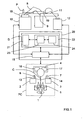
- FIG. 1 We first refer to the figure 1 to describe an exemplary embodiment, not limiting, of an installation according to the invention adapted to minimally invasive telesurgery.
- the illustrated telesurgery installation is for example formed from the Da Vinci ® installation of the company Intuitive Surgical Inc. It schematically comprises a PC control station comprising a chair 1 allowing a surgeon C to install in front of a console equipped with a control keyboard (not shown), a first manual control 2 for the left hand, a second manual control 3 for the right hand, a display device 4, here stereoscopic type, and a set of control pedals 5.
- Each manual control 2, 3 comprises for example a control lever 6, 7 (of the "joystick” type), intended to control one of the manipulator arms 8, 9 of a robot 10, on which one will return further, as well as the manipulator arm 11 of a stereoscopic camera 12, which will also be discussed later, and one or more buttons 13,14 control (sensory type, or push button, or “mouse” ).
- the set of pedals 5 includes for example a pedal for associating a manual control 2, 3 to the control of the intervention robot 10, a pedal for associating a manual control 2, 3 to the control of the camera 12, and a pedal for associating a manual control 2, 3 to the control of a control module 15 of the installation, which will be discussed later.
- the control keyboard, the manual controls 2 and 3, and the set of control pedals 5 constitute a man / machine interface.
- the display device 4 comprises, here, a first screen 16 for displaying real two-dimensional images (2D) delivered by a first path of the camera 12 and intended for the left eye of the surgeon C, and a second screen 17, for displaying real two-dimensional (2D) images delivered by a second path of the camera 12 and intended for the right eye of the surgeon C.
- the interventional robot 10 is intended to be placed close to the operating table 18, on which the patient P is installed to be operated minimally. It generally comprises two manipulator arms 8 and 9 provided with ends adapted to the operation and intended to be introduced into the body of the patient P via incisions.
- the stereoscopic camera 12 comprises a manipulator arm 11 whose end supports two endoscopic optical fibers 19 defining two image acquisition channels.
- the interventional robot 10 and the endoscopic camera 12 can be combined to constitute a "robot master”.
- the installation further comprises a control unit 20, for example arranged in the form of a work station, comprising the control module 15 and a resetting device according to the invention D, which will be discussed later.
- the control module 15 is coupled to the console of the PC control station, the interventional robot 10, the stereoscopic camera 12 and the resetting device D.
- the registration device D is intended, in a general manner, to register in real time known patterns, which are characteristic of a region (here in which an operation must be carried out), on (real) images of this region.
- the patterns are three-dimensional (3D), but they could be two-dimensional (2D), at least for some of them.
- This device D firstly comprises a memory 21, storing three-dimensional patterns (3D) representative of characteristic portions of the region in which the intervention is to take place, and of known position and orientation with respect to a common reference frame ( or preoperative reference).
- the device D also comprises a processing module 22 coupled to the memory 21 and loaded, when it receives the designations, on the one hand, at least a portion of the observation image of the intervention region, taken under an angle chosen by the endoscopic camera 12 and delivered by the control module 15, and on the other hand, of at least one attribute representative of the designated portion, to determine in the memory 21 a 3D pattern which is representative of this portion designated, taking into account the designated attribute and the chosen viewing angle, and then resetting the determined 3D pattern to the designated image portion.
- 3D three-dimensional patterns
- a set of 3D patterns can be a 3D model. Therefore, the registration may relate not only to a 3D pattern, but also to a 3D model.
- a 3D model can be representative of the coronary tree, this 3D model then consisting of a multiplicity of 3D patterns representative of characteristic structures of the coronary tree, such as for example arteries, junctions and bifurcations.
- characteristic structures of the coronary tree such as for example arteries, junctions and bifurcations.
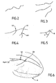
- two types of structures are defined. A first type groups curves representing the arteries, while a second type groups characteristic elements, such as junctions or bifurcations. These different types are illustrated on the Figures 2 to 5 .
- the figure 2 illustrates a representative pattern of a coronary artery
- the figure 3 illustrates a representative pattern of a configuration of three coronary arteries
- the figure 4 illustrates a representative pattern of a configuration of three bifurcations on a coronary artery
- the figure 5 illustrates a representative pattern of an angle ⁇ characteristic of a bifurcation between two coronary arteries.
- a bifurcation is defined, first, by an index (integer identifying the bifurcation), a second part, by two indexes (Art1 and Art2 which identify the two arteries concerned), and a third on the other hand, by a point (triplet of coordinates of the bifurcation in the pre-operative repository).
- an artery is defined on the one hand by an index (integer identifying the artery), and on the other hand by a set of parameters of a B-spline composing the central line of the artery ( quadruplet (xi, yi, zi, ui) in which (xi, yi, zi) is a triplet defining each control point of the artery in the pre-operative repository, and ui denotes a node of the B-spline whose value is between 0 and 1).
- obtaining 3D patterns of a region of intervention such as an organ such as the heart, firstly requires a three-dimensional modeling, and possibly temporal (3 D + t), the region of intervention from images obtained by medical imaging (MRI, scanner, etc.).
- MRI medical imaging
- 3D volume model
- the volume model (3D) is animated from a 3D + t model of the coronary network of the modeled heart, obtained from sequences of angiographic images (X-rays), also called coronarographies , taken at different angles and for several cycles, and synchronized with respect to an electrocardiogram (ECG).
- ECG electrocardiogram
- the 3D patterns are therefore fractions (or portions) characteristic of the 3D coronary tree (or network) whose positions are known with respect to the volume model (3D). from the heart of the patient P.
- the preoperative reference system relative to which the positions of the 3D units and the heart are defined is usually that of the external envelope of the patient P. It is in fact with respect to this external envelope that the intervention robot can be calibrated. 10 and the endoscopic camera 12. In addition, the fact of reporting the position of the heart, and therefore of its coronary network, with respect to the outer casing makes it possible to recalibrate the patient with respect to the robot in the operating room.
- a 3D anatomical model of the patient's body is also determined, at least in a large portion containing the subject area of the procedure, always from images obtained by medical imaging.
- the positions, orientations and configurations of the patterns (and models) 3D are stored in the memory 21 with respect to a common reference defined from marks placed on the outer envelope of the patient P.
- the 3D model of the heart of the patient P is also stored in the memory 21.
- the subject of the invention is not the preoperative planning phase of the surgical operation, it will not be described here. Therefore, the following describes the implementation of the device D according to the invention, within an installation according to the invention, in the operating phase.
- the preoperative planning phase which is only optional, is in particular to determine the three optimal incision points, which will allow to introduce the ends of the manipulator arms 8, 9 and 11 of the interventional robot 10 and the endoscopic camera 12, taking into account the 3D anatomical model of the body of the patient P and parameters, such as the dexterity and accessibility of the target region. It also consists in determining the optimal configuration of the manipulator arms 8 and 9 of the interventional robot 10 in order to avoid collisions and to obtain maximum separation.
- the device D intervenes within the installation once the arm 11 and the endoscopic camera 12 (possibly endoscopic) have been calibrated.
- An example of an endoscopic calibration method is described in the document F. Mourgues et al "Flexible calibration of actuated stereoscopic endoscope for overlay in robot assisted surgery", Proc. of MICCAI, Volume 2488 of LNCS, Spinger (2002), 25-34 .
- the calibration data are preferably stored in a memory of the control module 15.
- Incisions are then made in the patient's body P at the optimal incision points determined during the pre-operative planning phase.
- the manipulator arms 8 and 9 of the interventional robot 10 and 11 of the endoscopic camera are then placed in the optimal configuration, also determined during the preoperative planning phase, and their respective ends are introduced into the patient's body. by the incisions. It is recalled that the determination of the optimal incision points is a preferred but not mandatory option, as the positions of the robot arms and the endoscope can be determined empirically by the surgeon.
- the two channels of the endoscopic camera 12 deliver their respective 2D image sequences to the control module 15, which transmits them to the display device 4 so that they are displayed on the screens 16 and 17.
- the surgeon C can then observe the region in which is implanted the heart H object of the intervention, under the observation angle of the endoscopic camera 12.
- the figure 6 is an image of heart H of the type observed by surgeon C on screens 16 and 17.
- model3D here of the coronary tree
- This can be done manually or by an external registration of the patient, installed on the operating table, with its pre-operative model.
- the external registration is first to point with the end of the robot several radiopaque markers previously glued on the patient's chest, and previously segmented in the scanner images. Then, we calculate the rigid transformation between the dotted markers and the segmented markers.
- This initial rigid transformation makes it possible to pass from the pre-operative repository (referential in which the patterns of the 3D model to be recalibrated) to the reference frame of the base of the robot, and to the repository of the endoscopic camera (then using the calibration of the endoscope).
- This external registration technique is described in particular in the document E. Coste-Maniere et al "Optimal planning ofrobotically assisted heart surgery: Precision transfer in the operating room, B. Siciliano and P. Dario, eds, Springer Tracts In Advanced Robotics, Experimental Robotics VIII, Volume 5, Springer (2002), 424-434 .
- the surgeon C designates at least a portion of the images displayed on his screens 16 and 17 and at least one attribute representative of each image portion using his man / machine interface.
- the designation of a portion is for example by selecting the portion on the image with a mouse.
- the designation of an attribute is made either by a voice command or by selection from a list displayed on the screens 16 and 17 or on an auxiliary screen.
- the squares A1 to A3 materialize the places on which the surgeon C "clicks" with his mouse to designate three portions of the region which seem significant to him.
- the square B materializes the place on which the surgeon C "clicks" with his mouse to designate the portion of the region that seems significant to him.
- the attributes are standard information (or classes) which each describe a known local characteristic or a known local configuration, or generally any information enabling the processing module 22 of the device D to determine in the memory 21 the corresponding 3D pattern. .
- the device D transmits them to its processing module 22, so that it determines in the memory 21 a 3D pattern that seems representative of the designated portion or portions, taking into account the (or) the designated attribute (s).
- This determination is provided by an extraction module 23 coupled to the memory 21. Then, the processing module 22 must perform the registration of this pattern (and possibly the entire 3D model of which it is part). This is to determine how to orient and position the pattern so that it can be superimposed on the portion designated by the surgeon, given the angle at which the region of intervention is observed by the endoscopic camera.
- the registration is preferably performed by a registration module 24 of the processing module 22. Furthermore, this registration is preferably rigid, by minimizing a criterion constructed from the measurement equations.
- the measurement equations are deduced here from the hypotheses provided by the surgeon, when he thinks to recognize a portion, such as an artery or a bifurcation between known arteries, or directly determined by the registration module 24.
- another type of registration could be considered, including an affine registration.
- the rigid registration consists in determining at least one measurement equation from the designation of a portion of an image, an attribute and at least one hypothesis on the identity of the pattern determined by the module. 23. This registration may also take into account the 3D model of the heart when it is stored in the memory 21.
- the registration module 24 generates several sets of equations corresponding to the different possible hypotheses and then optimizes the registration parameters by minimizing a criterion. It then classifies the readjustments obtained according to their relevance and selects the best registration.
- the parameter estimation method is described in particular in the T. Vieville et al "Implementing a multi-model estimation method", The International Journal of Computer Vision, 44 (2001), 41-64 .
- the entire 3D model which includes said pattern.
- it is the entire 3D model, seen from the angle of observation of the endoscopic camera, and not only the determined 3D pattern and recaled, which can be superimposed on the image displayed or observed.
- some portions of the 3D model may not be visible due to the viewing angle.
- the processing module 22 can then transmit to the control module 15 the position data of the recalibrated 3D pattern (or of the entire 3D model of which it forms part), in the (calibration) frame of the displayed image (or observed, when the surgeon is equipped with observation glasses), and the image data which define this pattern (or model) 3D, so that it orders the display device 4 its display superimposed on the images of observed by the endoscopic camera 12 (or observed in the glasses).
- a superposition of a large 3D pattern on a heart image is illustrated on the figure 6 .
- the squares D1 and D2 represent the places on which the surgeon C clicked with his mouse to designate two portions of the intervention area that seemed significant to him, and the fraction of the coronary network superimposed on the image of the heart H materializes. the 3D pattern recaled by the device D.
- the designations made by the surgeon C may not allow the extraction module 23 to determine the 3D pattern that corresponds to the selected portion, or the registration module 24 to perform an appropriate registration, thereby causing a bad superposition of the pattern (or model) 3D on the displayed image. Consequently, the processing module 22 can be arranged to precisely determine the position of the region observed in the reference frame by successive readjustments, each relying on the extraction of a new 3D pattern following the designation of at least one another portion of observation images and at least one attribute representative of this other portion.
- the 3D pattern determined by the extraction module 23 is not superimposed on the image of the region observed at the portion selected by the surgeon C or the recaled 3D pattern is superimposable, but it does not correspond not to the structure observed by the surgeon on the selected portion. The surgeon must then make a new designation to converge the resetting operation.
- the control module 15 which automatically notices the error and sends a message to the surgeon, requesting new designations from him.
- the registration device D On receipt of these new designations, the registration device D reiterates the treatments presented above by taking into account the new and old designations. He may in particular, when arranged for this purpose, calculate new hypotheses and measurement equations.
- a correspondence table between the 3D patterns and information data which represents them may be for example the name of the pattern, such as for example the name of an artery and / or its possible ramifications, or coordinates of a target point, or operating data recorded during the phase of planning, such as the identification of a stenosis or a calcification zone.
- the processing module 22 can be configured to deliver the information data associated with a 3D pattern (recalibrated or not) when it receives the order from the control module 15 (for example in the case of request of the surgeon C).
- a 3D pattern for example in the case of request of the surgeon C.
- the control module 15 can also be designed, each time it receives a request designating a 3D pattern of the region observed, so as, firstly, order the resetting device D to determine position data representative of the position of this 3D pattern relative to the calibration reference, taking into account the registration, and secondly, to determine piloting instructions intended to move the manipulator arms 8 and 9 of the interventional robot 10 in the vicinity of the portion of region that corresponds to the designated 3D pattern.
- the installation presented above can be used for other types of operation, such as open liver or breast surgery.
- the installation according to the invention makes it possible to guide a user in the performance of his task in an environment where he has only partial and / or distorted vision, and / or in an environment difficult.
- the resetting device D according to the invention can be used in other applications than those presented above. It can in particular be used in installations dedicated solely to localization guidance (without the intervention of a teleoperated robot), and in particular in urban areas.
- an installation embedded in a motor vehicle comprising one or more cameras, delivering to a control module real images of the environment so that they are displayed on screens installed in the passenger compartment, and a resetting device D coupled to said control module.
- the installation can also be coupled to an onboard GPS-based satellite guidance device.
- the registration device D stores in its memory representative patterns of the environment (or region) in which the vehicle can evolve and determined from digital recordings previously made. These reasons, whose positions are defined in a chosen landmark, are for example facades of buildings, or buildings or remarkable sites, or statues or works of art.
- the memory may also include a volume model of the environment, as well as a correspondence table between the patterns and information data on these patterns.
- the installation can be used.
- the control module is loaded here, when it receives from a passenger of the vehicle a request designating a pattern of the observed region (which he has selected in the list of patterns stored using a mouse or by exercising a pressure on a touch display screen), order the resetting device D to determine position data representative of the position of this pattern relative to the calibration reference, given the registration induced by the offsets between the reference mark selected and the calibration mark, and then determine driving instructions to guide the driver of the vehicle to the portion of the region that corresponds to this pattern.
- the control module may possibly rely on the vehicle position data delivered by the GPS device to determine the piloting instructions.
- the pattern Once the vehicle arrived on site, the pattern may be optionally superimposed on the actual image of the region portion, and information data associated with said pattern may be issued to the passenger.
- the registration device D receives from a passenger of the vehicle the designations of at least one portion of the region observed and displayed (which he has selected with the aid of a mouse or by exerting pressure on the tactile display screen) and at least one attribute representative of this portion, such as for example the nature of a building (house, school, town hall, museum, church) or a place (garden, park, square) or object (statue, sculpture, work of art), and determines in its memory the pattern that best corresponds to that designated portion, taking into account the attribute designated and the chosen viewing angle. Then, he recalibrates the determined pattern on the designated image portion.
- the device according to the invention is advantageously implanted in a communication equipment, such as for example a mobile telephone, equipped with a location function, for example by triangulation or by GPS, and a camera, as well as possibly an inertial unit.
- a communication equipment such as for example a mobile telephone, equipped with a location function, for example by triangulation or by GPS, and a camera, as well as possibly an inertial unit.
- the processing module 22 of the resetting device D and the control module 15 of the installations can be made in the form of electronic circuits, software (or computer) modules, or a combination of software modules and electronic circuits.
- the invention also relates to a method dedicated to the real-time registration of known patterns, characteristic of a region, on images of this region.
Landscapes
- Health & Medical Sciences (AREA)
- Engineering & Computer Science (AREA)
- Life Sciences & Earth Sciences (AREA)
- Surgery (AREA)
- Physics & Mathematics (AREA)
- Heart & Thoracic Surgery (AREA)
- Veterinary Medicine (AREA)
- Biomedical Technology (AREA)
- Public Health (AREA)
- Medical Informatics (AREA)
- Molecular Biology (AREA)
- Animal Behavior & Ethology (AREA)
- General Health & Medical Sciences (AREA)
- Nuclear Medicine, Radiotherapy & Molecular Imaging (AREA)
- Biophysics (AREA)
- Pathology (AREA)
- Robotics (AREA)
- Theoretical Computer Science (AREA)
- Computer Vision & Pattern Recognition (AREA)
- General Physics & Mathematics (AREA)
- Radiology & Medical Imaging (AREA)
- Optics & Photonics (AREA)
- Signal Processing (AREA)
- Gynecology & Obstetrics (AREA)
- Human Computer Interaction (AREA)
- Geometry (AREA)
- Image Processing (AREA)
- Endoscopes (AREA)
- High Energy & Nuclear Physics (AREA)
- Pharmaceuticals Containing Other Organic And Inorganic Compounds (AREA)
- Processing Or Creating Images (AREA)
Abstract
Description
L'invention concerne le domaine du traitement de données d'images, et plus précisément le recalage en temps réel de données d'images représentant des motifs connus sur des images d'observation.The invention relates to the field of image data processing, and more specifically the real-time registration of image data representing known patterns on observation images.
Dans un certain nombre de domaines, il est important de savoir précisément, à chaque instant, comment l'on est positionné par rapport à un lieu ou un objet, ou plus généralement une région.In a number of areas, it is important to know precisely, at each moment, how one is positioned in relation to a place or an object, or more generally a region.
C'est par exemple le cas dans le domaine de la chirurgie, notamment lorsqu'elle met en oeuvre une technique dite "mini-invasive". Dans ce cas, le champ opératoire est observé par une caméra endoscopique introduite dans le corps du patient et délivrant des images sur un
ou plusieurs moniteurs (ou dans des lunettes d'observation) en regard duquel (desquelles) se trouve installé un chirurgien. Dans le cas d'une procédure assistée par un robot, le chirurgien pilote à distance les bras manipulateurs du robot dont les extrémités sont également introduites dans le corps du patient. C'est notamment le cas de l'installation Da Vinci ® de la société Intuitive Surgical Inc qui dispose, d'une part, d'un afficheur stéréoscopique, permettant au chirurgien de visualiser en trois dimensions (3D) la région d'intervention, et d'autre part, de manettes de pilotage et de pédales de commande permettant au chirurgien d'adresser des instructions de pilotage et de commande au robot.This is for example the case in the field of surgery, especially when it implements a so-called "minimally invasive" technique. In this case, the operating field is observed by an endoscopic camera introduced into the body of the patient and delivering images on a
or several monitors (or in glasses of observation) in front of which (of) is installed a surgeon. In the case of a robot assisted procedure, the surgeon remotely controls the manipulator arms of the robot whose ends are also introduced into the body of the patient. This is particularly the case of the Da Vinci ® installation of Intuitive Surgical Inc which has, on the one hand, a stereoscopic display, allowing the surgeon to visualize in three dimensions (3D) the region of intervention, and on the other hand, joysticks and control pedals allowing the surgeon to address control and control instructions to the robot.
Cette technique opératoire est particulièrement intéressante pour le patient dans la mesure
où elle est très peu invasive. Mais, elle est particulièrement délicate à mettre en oeuvre du fait qu'elle n'offre au chirurgien, d'une part, qu'une vision partielle et en partie déformée de la région dans laquelle il doit intervenir, en raison de l'utilisation d'une caméra endoscopique, et d'autre part, qu'un espace d'intervention exigu et encombré par les bras manipulateurs du robot et par la caméra endoscopique. En outre, certaines régions, telles que le coeur, étant animées, cela accentue la difficulté de l'intervention.This surgical technique is particularly interesting for the patient as far as
where it is very minimally invasive. But, it is particularly difficult to implement because it offers the surgeon, on the one hand, a partial and partially distorted view of the region in which he must intervene, because of the use of an endoscopic camera, and secondly, that a space of intervention cramped and congested by the manipulator arms of the robot and by the endoscopic camera. In addition, some regions, such as the heart, being animated, this accentuates the difficulty of the intervention.
Afin d' améliorer la situation, il a été proposé de mettre en oeuvre une phase de modélisation pré-opératoire. Dans une telle phase pré-opératoire, on effectue tout d'abord une modélisation tridimensionnelle, et éventuellement temporelle, de la région objet de l'intervention à partir d'images obtenues par imagerie médicale. Dans le cas d'un coeur, on détermine également le réseau coronaire à l'aide de séquences angiographiques, puis on effectue un recalage de ce réseau coronaire sur la surface du coeur obtenue par IRM. On détermine ensuite un modèle anatomique de la partie du corps du patient qui contient la région objet de l'intervention, toujours à partir d'images obtenues par imagerie médicale.In order to improve the situation, it has been proposed to implement a preoperative modeling phase. In such a pre-operative phase, firstly a three-dimensional and possibly temporal modeling of the intervention region of the image from images obtained by medical imaging. In the case of a heart, the coronary network is also determined using angiographic sequences, and then this coronal network is rescaled to the surface of the heart obtained by MRI. An anatomical model of the part of the patient's body that contains the area of the procedure is then determined, always from images obtained by medical imaging.
Puis, on détermine, d'une part, les points d'incision optimaux compte tenu du modèle anatomique et de paramètres, tels que la dextérité et l'accessibilité de la région visée, et d'autre part, la configuration optimale des bras du robot, de manière à éviter les collisions et à obtenir une séparation maximale, notamment.Then, we determine, on the one hand, the optimal incision points taking into account the anatomical model and parameters, such as the dexterity and the accessibility of the targeted region, and on the other hand, the optimal configuration of the arms of the robot, so as to avoid collisions and to obtain maximum separation, in particular.
Une fois la phase pré-opératoire terminée, le chirurgien peut procéder à l'intervention. Le patient est alors installé sur la table d'opération, puis on calibre l'endoscope à l'aide d'une grille posée sur la table d'opération et observée selon différents points de vue. Le corps du patient est alors incisé au niveau des points d'incisions optimaux précédemment déterminés. Puis, les bras du robot sont placés dans la configuration optimale précédemment déterminée, et leurs extrémités, tout comme celle de la caméra endoscopique, sont introduites dans le corps du patient par les incisions. L'intervention peut alors commencer.Once the preoperative phase is over, the surgeon can proceed with the procedure. The patient is then placed on the operating table, and the endoscope is calibrated using a grid placed on the operating table and observed from different points of view. The body of the patient is then incised at the points of optimal incisions previously determined. Then, the arms of the robot are placed in the optimal configuration previously determined, and their ends, like that of the endoscopic camera, are introduced into the body of the patient by the incisions. The intervention can then begin.
Malgré la phase pré-opératoire, le chirurgien peut encore avoir des difficultés à localiser avec précision la zone d'intervention. Cela peut notamment survenir lors d'une intervention sur un organe tel que le coeur. Il peut en effet être difficile de localiser l'artère interventriculaire du fait d'une quantité trop importante de graisse à la surface de l'épicarde. Il est également possible de confondre la branche marginale de l'artère circonflexe ou la branche diagonale (particulièrement développée) avec l'artère interventriculaire du fait du fort grossissement de la caméra endoscopique et/ou du faible champ de vision et/ou du faible recul possible et/ou d'un mauvais positionnement de l'ouverture effectuée dans le péricarde.Despite the preoperative phase, the surgeon may still have difficulty in accurately locating the intervention area. This can especially occur during an intervention on an organ such as the heart. It can indeed be difficult to locate the interventricular artery due to too much fat on the surface of the epicardium. It is also possible to confuse the marginal branch of the circumflex artery or the diagonal branch (particularly developed) with the interventricular artery because of the high magnification of the endoscopic camera and / or the weak field of vision and / or the slight recoil possible and / or poor positioning of the opening made in the pericardium.
En complément de ces difficultés à repérer les cibles opératoires, le chirurgien rencontre des difficultés à localiser la caméra endoscopique et par conséquent à estimer l'angle sous lequel il observe la région d'intervention. Enfin, le retour tactile faisant défaut, il n'est pas possible de déterminer la zone à opérer en exerçant sur elle des pressions avec les extrémités des bras du robot.In addition to these difficulties in locating operative targets, the surgeon encounters difficulties in locating the endoscopic camera and consequently in estimating the angle at which he observes the region of intervention. Finally, the tactile feedback is lacking, it is not possible to determine the area to operate by exerting pressure on it with the ends of the robot's arms.
En résumé, le chirurgien éprouve de réelles difficultés à déterminer la position précise de la zone (ou portion) de la région observée, dans laquelle il doit intervenir, par rapport aux positions connues des extrémités des bras du robot d'intervention.In summary, the surgeon has real difficulties in determining the precise position of the area (or portion) of the observed region, in which it must intervene, relative to the known positions of the ends of the arms of the intervention robot.
Pour améliorer encore la situation, il a été proposé d'assister le chirurgien en superposant sur les images endoscopiques de la région observée un motif représentatif d'un élément caractéristique de la portion de région où doit s'effectuer l'intervention, ou d'une portion voisine. Ces motifs sont préalablement extraits des modélisations numériques, effectuées à partir des images obtenues par imagerie médicale. Mais, une telle assistance ne suffit pas, notamment lorsque la région d'intervention comporte plusieurs éléments caractéristiques sensiblement identiques (soit naturellement, soit du fait de l'angle d'observation), comme dans le cas du réseau coronarien.To further improve the situation, it has been proposed to assist the surgeon by superimposing on the endoscopic images of the observed region a representative pattern of a characteristic element of the portion of the region where the procedure is to be performed, or of a neighboring portion. These patterns are previously extracted from digital modelings, made from images obtained by medical imaging. But such assistance is not enough, especially when the region of intervention has several substantially identical characteristic elements (either naturally or because of the angle of observation), as in the case of the coronary network.
Des difficultés similaires de détermination précise des positions de lieux ou objets, via des portions d'images réelles, surviennent également dans d'autres domaines techniques, et notamment dans le domaine du guidage urbain.Similar difficulties in precisely determining the positions of places or objects, via portions of real images, also occur in other technical fields, and particularly in the field of urban guidance.
L'invention a donc pour but de remédier à tout ou partie des inconvénients précités.The invention therefore aims to remedy all or part of the aforementioned drawbacks.
Elle propose à cet effet un dispositif dédié au recalage en temps réel de motifs (par exemple tridimensionnels (3D)) connus, caractéristiques d'une région, sur des images (réelles) de cette région.To this end, it proposes a device dedicated to the real-time registration of known (for example three-dimensional (3D)) patterns, characteristic of a region, on (real) images of this region.
Ce dispositif se caractérise par le fait qu'il comprend, d'une part, une mémoire dans laquelle sont stockés des motifs représentatifs de portions d'une région choisie et de position et d'orientation connues par rapport à un référentiel commun, et d'autre part, des moyens de traitement chargés, lorsqu'ils reçoivent la désignation d'au moins une portion d'image d'observation de la région choisie, prise sous un angle choisi, et d'au moins un attribut représentatif de cette portion, de déterminer dans la mémoire un motif représentatif de la portion désignée, compte tenu de l'attribut désigné, puis de recaler le motif déterminé sur la portion d'image désignée compte tenu de l'angle choisi.This device is characterized in that it comprises, on the one hand, a memory in which are stored patterns representative of portions of a selected region and of known position and orientation with respect to a common reference frame, and on the other hand, loaded processing means, when they receive the designation of at least a portion of an observation image of the selected region, taken at a selected angle, and at least one attribute representative of this portion , determining in the memory a pattern representative of the designated portion, taking into account the designated attribute, and then resetting the determined pattern on the designated image portion taking into account the chosen angle.
Le dispositif selon l'invention peut comporter d'autres caractéristiques qui pourront être prises séparément ou en combinaison, et notamment:
- * des moyens de traitement capables d'effectuer le recalage par des désignations successives de portions d'images d'observation de la région choisie et/ou d'attributs représentatifs de ces portions,
- * une mémoire capable de stocker un modèle tridimensionnel représentatif de la région au sein du référentiel choisi. Dans ce cas, les moyens de traitement sont préférentiellement chargés d'effectuer leur(s) recalage(s) à partir, notamment, du modèle tridimensionnel stocké,
- * des moyens de traitement capables de déterminer au moins une équation de mesure à partir de la désignation d'une portion d'image, d'un attribut et d'au moins une hypothèse, et de procéder à la détermination du motif et à son recalage en fonction de l'équation de mesure déterminée. Plusieurs équations de mesure peuvent être déterminées à partir de la désignation de plusieurs portions d'images, d'attributs et d'hypothèses. Dans ce cas, les moyens de traitement procèdent à la détermination du motif et à son recalage en fonction d'une combinaison des équations de mesure déterminées. Le recalage est par exemple de type rigide par minimisation d'un critère choisi prenant en compte les équations de mesure déduites des hypothèses. Par ailleurs, les hypothèses peuvent être transmises aux moyens de traitement par l'utilisateur qui effectue les désignations, ou bien être directement déterminées par les moyens de traitement,
- *des moyens de traitement capables de délivrer des données d'images représentatives d'un motifrecalé afin qu'on puisse l'observer en même temps que les images d'observation, et de façon superposée, sur la portion d'image désignée correspondante, une fois le recalage effectué,
- * une mémoire capable de stocker une table de correspondance entre les motifs et des données d'information qui les représentent. Dans ce cas, les moyens de traitement sont avantageusement chargés de délivrer, chaque fois qu'ils en reçoivent l'ordre, des données d'information représentatives d'un motif recalé,
- * des moyens de traitement capables de délivrer sensiblement en même temps, chaque fois qu'ils en reçoivent l'ordre, des données d'images représentatives d'un motif recalé et les données d'information représentatives de ce motif.
- processing means capable of performing the registration by successive designations of portions of observation images of the chosen region and / or representative attributes of these portions,
- a memory capable of storing a three-dimensional model representative of the region within the chosen reference frame. In this case, the processing means are preferably responsible for performing their registration (s) from, in particular, the stored three-dimensional model,
- processing means capable of determining at least one measurement equation from the designation of a portion of an image, an attribute and at least one hypothesis, and to proceed with the determination of the pattern and its resetting according to the determined measurement equation. Several measurement equations can be determined from the designation of several image portions, attributes and assumptions. In this case, the processing means proceed to the determination of the pattern and its registration according to a combination of the measurement equations determined. The registration is for example of rigid type by minimization of a chosen criterion taking into account the measurement equations deduced from the hypotheses. Moreover, the hypotheses can be transmitted to the processing means by the user who makes the designations, or be directly determined by the processing means,
- processing means capable of delivering image data representative of a patterned pattern so that it can be observed at the same time as the observation images, and superimposed on the corresponding designated image portion, once the registration is completed,
- a memory capable of storing a correspondence table between the patterns and information data which represents them. In this case, the processing means are advantageously responsible for delivering, each time they receive the order, information data representative of a recalibrated pattern,
- processing means capable of delivering substantially at the same time, each time they receive the order, image data representative of a recalibrated pattern and the information data representative of this pattern.
L'invention concerne en outre une installation de guidage par localisation comprenant, d'une première part, des moyens d'observation pouvant délivrer des images d'une région choisie sous un angle choisi, d'une deuxième part, un afficheur (par exemple un ou plusieurs moniteurs d'ordinateur ou des lunettes d'observation) permettant d'afficher ces images, d'une troisième part, une interface homme/machine permettant à un utilisateur de désigner au moins une portion de la région représentée par les images affichées et au moins un attribut représentatif de cette portion, et d'une quatrième part, un dispositif de recalage du type de celui présenté ci-avant, alimenté en portion(s) et attribut(s) désignés par l'interface homme/machine et délivrant des données d'images représentatives d'un motifrecalé de sorte que ce dernier soit superposé par l'afficheur sur la portion désignée affichée, une fois le recalage effectué.The invention furthermore relates to a location guidance system comprising, firstly, observation means capable of delivering images of a selected region at a selected angle, and secondly a display (for example one or more computer monitors or observation glasses) for displaying these images, and thirdly, a human / machine interface allowing a user to designate at least a portion of the region represented by the displayed images. and at least one attribute representative of this portion, and fourthly, a resetting device of the type of the one presented above, fed in portions and attribute (s) designated by the man / machine interface and delivering image data representative of a patterned pattern so that the latter is superimposed by the display on the designated portion displayed, once the registration is made.
Les moyens d'observation peuvent comprendre des moyens d'acquisition, par exemple de type endoscopique, dont la position est connue à chaque instant par rapport à un référentiel de calibration, à partir duquel est définie la position de la région observée, et capable de délivrer des images d'observation à l'afficheur.The observation means may comprise acquisition means, for example of the endoscopic type, the position of which is known at each instant with respect to a calibration reference frame, from which the position of the region observed is defined, and capable of deliver observation images to the display.
Lorsque l'installation ne sert qu'au guidage, par exemple urbain, elle comprend préférentiellement des moyens de contrôle chargés, lorsqu'ils reçoivent une requête désignant un motif de la région observée, d'ordonner au dispositif de recalage de déterminer des données de position représentatives de la position de ce motif par rapport au référentiel de calibration, compte tenu du recalage, puis de déterminer des instructions de pilotage destinées à guider l'utilisateur vers la portion qui correspond à ce motif.When the installation only serves for guidance, for example urban, it preferably comprises loaded control means, when they receive a request designating a pattern of the region observed, to order the registration device to determine data of position representative of the position of this pattern relative to the calibration reference, given the registration, and then to determine piloting instructions for guiding the user to the portion that corresponds to this pattern.
Lorsque l'installation sert aux interventions chirurgicales, elle peut comprendre un robot d'intervention comportant des bras dont les positions respectives par rapport au référentiel de calibration sont connues à chaque instant et qui peuvent être pilotés à distance par des instructions fournies par un utilisateur via l'interface homme/machine. Mais, elle comprend également des moyens de contrôle couplés au dispositif de recalage et à l'interface homme/machine, et chargés, lorsqu' ils reçoivent une requête désignant un motif de la région observée, d'une part, d'ordonner au dispositif de recalage de déterminer des données de position représentatives de la position de ce motif par rapport au référentiel de calibration compte tenu du recalage, et d'autre part, de déterminer des instructions de pilotage destinées à déplacer les bras du robot au voisinage de la portion de région correspondant au motif désigné.When the installation is used for surgical procedures, it may comprise an intervention robot comprising arms whose respective positions relative to the calibration reference system are known at any time and which can be controlled remotely by instructions provided by a user via the man / machine interface. But, it also comprises control means coupled to the registration device and the man / machine interface, and loaded, when they receive a request designating a pattern of the region. observed, on the one hand, to order the resetting device to determine position data representative of the position of this pattern relative to the calibration reference system in view of the registration, and secondly, to determine piloting instructions intended to move the arms of the robot in the vicinity of the region portion corresponding to the designated pattern.
L'invention concerne également un procédé dédié au recalage en temps réel de motifs (par exemple 3D) connus, caractéristiques d'une région, sur des images de cette région, et consistant à :
- * stocker dans une mémoire des motifs représentatifs de portions d'une région choisie et de position et d'orientation connues par rapport à un référentiel commun,
- * observer sous un angle choisi la région choisie et délivrer en temps réel des images d'observation de cette région,
- * désigner au moins une portion d'image d'observation de la région choisie et au moins un attribut représentatif de cette portion,
- * déterminer dans la mémoire un motif représentatif de la portion désignée, compte tenu de l'attribut désigné, et
- * recaler le motif sur la portion d'image désignée compte tenu de l'angle choisi.
- to store in a memory representative patterns of portions of a chosen region and of known position and orientation with respect to a common reference frame,
- * observe at a chosen angle the selected region and deliver real-time observation images of this region,
- * designate at least one portion of the observation image of the selected region and at least one attribute representative of this portion,
- * determine in the memory a representative pattern of the designated portion, having regard to the designated attribute, and
- * reshape the pattern on the designated image portion considering the chosen angle.
Le procédé selon l'invention peut comporter d'autres caractéristiques qui pourront être prises séparément ou en combinaison, et notamment:
- * on peut effectuer le recalage par des désignations successives de portions d'images d'observation de la région choisie et/ou d'attributs représentatifs de ces portions,
- * on peut stocker dans la mémoire un modèle 3D représentatif de la région dans le référentiel choisi, et effectuer chaque recalage au moins à partir de ce modèle 3D,
- * on peut effectuer un recalage de type rigide, par minimisation d'un critère choisi. Dans ce cas, on détermine préférentiellement au moins une équation de mesure à partir de la désignation d'une portion d'image, d'un attribut et d'au moins une hypothèse, et l'on procède à la détermination de motif et au recalage rigide en fonction de l'équation de mesure déterminée. On peut déterminer plusieurs équations de mesure à partir de la désignation de plusieurs portions d'images, d'attributs et d'hypothèses, constituant les contraintes, et procéder à la détermination du motif et à son recalage rigide en fonction d'une combinaison des équations de mesure déterminées. Certaines au moins des hypothèses peuvent être transmises par l'utilisateur effectuant les désignations, par exemple sous la forme d'attributs,
- * on peut délivrer des données d'images représentatives d'un motif recalé afin qu'il soit observé en même temps que les images d'observation, et de façon superposée, sur la portion d'image désignée correspondante,
- * on peut stocker dans la mémoire une table de correspondance entre les motifs et des données d'information représentatives de ces motifs, et délivrer sur requête des données d'information représentatives d'un motif,
- * on peut afficher les données d'images représentatives d'un motif recalé,
- * on peut procéder aux désignations via une interface homme/machine,
- * lorsque l'on reçoit une requête d'un utilisateur désignant un motif contenu dans la région observée, on peut déterminer des données de position représentatives de la position de ce motif par rapport au référentiel de calibration (à partir duquel est définie la position de la région observée), compte tenu du recalage, puis déterminer des instructions de pilotage destinées à guider l'utilisateur vers la portion qui correspond audit motif désigné,
- * on peut prévoir un robot d'intervention comportant des bras dont les positions respectives par rapport au référentiel choisi sont connues à chaque instant et peuvent être pilotés à distance par des instructions fournies par un utilisateur via l'interface homme/machine, et lorsque l'on reçoit une requête d'utilisateur désignant un motif de la région choisie, on peut déterminer des données de position représentatives de la position du motif par rapport au référentiel de calibration, compte tenu du recalage, puis déterminer des instructions de pilotage destinées à déplacer les bras du robot au voisinage de la portion de région correspondant au motif désigné.
- the registration can be carried out by successive designations of portions of observation images of the chosen region and / or representative attributes of these portions,
- * it is possible to store in the memory a 3D model representative of the region in the selected reference frame, and to perform each registration at least from this 3D model,
- * We can perform a rigid type of registration, by minimizing a chosen criterion. In this case, at least one measurement equation is preferably determined from the designation of an image portion, an attribute and at least one hypothesis, and the pattern determination and rigid registration according to the determined measurement equation. Several equations of measurement can be determined from the designation of several portions of images, attributes and hypotheses, constituting the constraints, and proceed to the determination of the pattern and its rigid registration according to a combination of the measurement equations determined. At least some of the hypotheses may be transmitted by the user performing the designations, for example in the form of attributes,
- image data representative of a recalibrated pattern can be outputted so that it is observed simultaneously with the observation images, and superimposed on the corresponding designated image portion,
- * it is possible to store in the memory a correspondence table between the patterns and information data representative of these patterns, and to deliver, on request, information data representative of a pattern,
- the image data representative of a rectified pattern can be displayed,
- * Designations can be made via a man / machine interface,
- when receiving a request from a user designating a pattern contained in the observed region, position data representative of the position of this pattern relative to the calibration reference (from which the position of the observed region), taking into account the registration, and then determining piloting instructions intended to guide the user towards the portion corresponding to said designated motive,
- an intervention robot may be provided comprising arms whose respective positions with respect to the chosen reference frame are known at all times and can be controlled remotely by instructions supplied by a user via the man / machine interface, and when the a user request is received designating a pattern of the selected region, position data representative of the position of the pattern relative to the calibration reference can be determined, taking into account the registration, and then determining control instructions for moving the arms of the robot in the vicinity of the region portion corresponding to the designated pattern.
D'autres caractéristiques et avantages de l'invention apparaîtront à l'examen de la description détaillée ci-après, et des dessins annexés, sur lesquels :
- la
figure 1 illustre de façon schématique un exemple de réalisation d'une installation selon l'invention, adapté à une application dans le domaine de la téléchirurgie mini-invasive, - la
figure 2 illustre de façon schématiqueun motif 3D représentatif d'une artère coronaire, - la
figure 3 illustre de façon schématiqueun motif 3D représentatif de trois artères coronaires voisines, - la
figure 4 illustre de façon schématiqueun motif 3D représentatif d'une artère coronaire et de trois bifurcations, - la
figure 5 illustre de façon schématiqueun motif 3D représentatif d'un secteur angulaire au niveau d'une bifurcation entre deux artères coronaires, et - la
figure 6 est une image d'un coeur sur laquelle a été superposé un modèle 3D, après recalage.
- the
figure 1 schematically illustrates an exemplary embodiment of an installation according to the invention, adapted to an application in the field of minimally invasive telesurgery, - the
figure 2 schematically illustrates a 3D representative of a coronary artery, - the
figure 3 schematically illustrates a representative 3D pattern of three neighboring coronary arteries, - the
figure 4 schematically illustrates a 3D representative of a coronary artery and three bifurcations, - the
figure 5 schematically illustrates a 3D pattern representative of an angular sector at a bifurcation between two coronary arteries, and - the
figure 6 is an image of a heart on which was superimposed a 3D model, after registration.
Les dessins annexés pourront non seulement servir à compléter l'invention, mais aussi contribuer à sa définition, le cas échéant.The attached drawings may not only serve to complete the invention, but also contribute to its definition, if any.
L'invention concerne d'une manière générale le recalage en temps réel de données d'images représentant des motifs connus, par exemple tridimensionnels (3D), caractéristiques d'une région, sur des images d'observation de cette région. Mais, elle concerne également les installations de guidage par localisation utilisant un tel recalage, comme par exemple les installations de guidage urbain et de téléchirurgie, en particulier de type "mini-invasif".The invention relates generally to the real-time registration of image data representing known patterns, for example three-dimensional (3D) characteristics of a region, on observation images of this region. But it also relates to location guidance facilities using such a registration, such as urban guidance and telesurgery, in particular of the "mini-invasive" type.
On se réfère tout d'abord à la
L'installation de téléchirurgie illustrée est par exemple constituée à partir de l'installation Da Vinci ® de la société Intuitive Surgical Inc. Elle comprend schématiquement un poste de commande PC comportant une chaise 1 permettant à un chirurgien C de s'installer devant une console équipée d'un clavier de commande (non représenté), d'une première commande manuelle 2 pour la main gauche, d'une seconde commande manuelle 3 pour la main droite, d'un dispositif d'affichage 4, ici de type stéréoscopique, et d'un ensemble de pédales de commande 5.The illustrated telesurgery installation is for example formed from the Da Vinci ® installation of the company Intuitive Surgical Inc. It schematically comprises a PC control station comprising a
Chaque commande manuelle 2, 3 comporte par exemple un levier de pilotage 6, 7 (de type "joystick"), destiné à piloter l'un des bras manipulateurs 8, 9 d'un robot 10, sur lequel on reviendra plus loin, ainsi que le bras manipulateur 11 d'une caméra stéréoscopique 12, sur laquelle on reviendra également plus loin, et une ou plusieurs touches 13,14 de commande (de type sensitif, ou bouton-poussoir, ou encore "souris").Each
L'ensemble de pédales 5 comporte par exemple une pédale permettant d'associer une commande manuelle 2, 3 au pilotage du robot d'intervention 10, une pédale permettant d'associer une commande manuelle 2, 3 au pilotage de la caméra 12, et une pédale permettant d'associer une commande manuelle 2, 3 au pilotage d'un module de contrôle 15 de l'installation, sur lequel on reviendra plus loin.The set of
Le clavier de commande, les commandes manuelles 2 et 3, et l'ensemble de pédales de commande 5 constituent une interface homme/machine.The control keyboard, the
Le dispositif d'affichage 4 comprend, ici, un premier écran 16, pour l'affichage d'images bidimensionnelles (2D) réelles délivrées par une première voie de la caméra 12 et destinées à l'oeil gauche du chirurgien C, et un second écran 17, pour l'affichage d'images bidimensionnelles (2D) réelles délivrées par une seconde voie de la caméra 12 et destinées à l'oeil droit du chirurgien C.The
Le robot d'intervention 10 est destiné à être placé à proximité de la table d'opération 18, sur laquelle est installé le patient P devant être opéré de façon mini-invasive. Il comprend généralement deux bras manipulateurs 8 et 9 munis d'extrémités adaptées à l'opération et destinées à être introduites dans le corps du patient P via des incisions.The
La caméra stéréoscopique 12 comporte un bras manipulateur 11 dont l'extrémité supporte deux fibres optiques endoscopiques 19 définissant deux voies d'acquisition d'images.The
Le robot d'intervention 10 et la caméra endoscopique 12 peuvent être réunis pour constituer un "maître robot".The
L'installation comporte en outre un ensemble de contrôle 20, par exemple agencé sous la forme d'une station de travail, comportant le module de contrôle 15 et un dispositif de recalage selon l'invention D, sur lequel on reviendra plus loin. Le module de contrôle 15 est couplé à la console du poste de commande PC, au robot d'intervention 10, à la caméra stéréoscopique 12 et au dispositif de recalage D.The installation further comprises a
Le dispositif de recalage D, selon l'invention, est destiné, d'une manière générale, à recaler en temps réel des motifs connus, qui sont caractéristiques d'une région (ici dans laquelle doit s'effectuer une opération), sur des images (réelles) de cette région. Dans ce qui suit, on considère que les motifs sont tridimensionnels (3D), mais ils pourraient être bidimensionnels (2D), au moins pour certains d'entre eux.The registration device D, according to the invention, is intended, in a general manner, to register in real time known patterns, which are characteristic of a region (here in which an operation must be carried out), on (real) images of this region. In what follows, we consider that the patterns are three-dimensional (3D), but they could be two-dimensional (2D), at least for some of them.
Ce dispositif D comprend tout d'abord une mémoire 21, stockant des motifs tridimensionnels (3D) représentatifs de portions caractéristiques de la région dans laquelle doit avoir lieu l'intervention, et de position et d'orientation connues par rapport à un référentiel commun (ou référentiel pré-opératoire). Le dispositif D comprend également un module de traitement 22 couplé à la mémoire 21 et chargé, quand il reçoit les désignations, d'une part, d'au moins une portion d'image d'observation de la région d'intervention, prises sous un angle choisi par la caméra endoscopique 12 et délivrées par le module de contrôle 15, et d'autre part, d'au moins un attribut représentatif de la portion désignée, de déterminer dans la mémoire 21 un motif 3D qui est représentatif de cette portion désignée, compte tenu de l'attribut désigné et de l'angle de prise de vue choisi, puis de recaler le motif 3D déterminé sur la portion d'image désignée.This device D firstly comprises a
Il est important de noter qu'un ensemble de motifs 3D peut constituer un modèle 3D. Par conséquent, le recalage peut porter non seulement sur un motif 3D, mais également sur un modèle 3D.It is important to note that a set of 3D patterns can be a 3D model. Therefore, the registration may relate not only to a 3D pattern, but also to a 3D model.
Par exemple dans le cas du coeur, un modèle 3D peut être représentatif de l'arbre coronarien, ce modèle 3D étant alors constitué d'une multiplicité de motifs 3D représentatifs de structures caractéristiques de l'arbre coronarien, comme par exemple des artères, des jonctions et des bifurcations. En fait, dans le cas d'un arbre coronarien, on définit deux types de structures. Un premier type regroupe des courbes représentant les artères, tandis qu'un second type regroupe des éléments caractéristiques, comme par exemple des jonctions ou des bifurcations. Ces différents types sont illustrés sur les
Plus précisément, la
Par exemple, une bifurcation est définie, d'une première part, par un index (entier identifiant la bifurcation), d'une deuxième part, par deux index (Art1 et Art2 qui identifient les deux artères concernées), et d'une troisième part, par un point (triplet de coordonnées de la bifurcation dans le référentiel pré-opératoire). De même, une artère est définie, d'une part, par un index (entier identifiant l'artère), et d'autre part, par un ensemble de paramètres d'une B-spline composant la ligne centrale de l'artère (quadruplet (xi, yi, zi, ui) dans lequel (xi, yi, zi) est un triplet définissant chaque point de contrôle de l'artère dans le référentiel pré-opératoire, et ui désigne un noeud de la B-spline dont la valeur est comprise entre 0 et 1).For example, a bifurcation is defined, first, by an index (integer identifying the bifurcation), a second part, by two indexes (Art1 and Art2 which identify the two arteries concerned), and a third on the other hand, by a point (triplet of coordinates of the bifurcation in the pre-operative repository). Similarly, an artery is defined on the one hand by an index (integer identifying the artery), and on the other hand by a set of parameters of a B-spline composing the central line of the artery ( quadruplet (xi, yi, zi, ui) in which (xi, yi, zi) is a triplet defining each control point of the artery in the pre-operative repository, and ui denotes a node of the B-spline whose value is between 0 and 1).
L'obtention des motifs 3D ne faisant pas l'objet de l'invention, elle ne sera pas décrite ici en détail. Une description précise d'un mode d'obtention est par exemple donnée dans l'article de
Il est simplement rappelé que l'obtention de motifs 3D d'une région d'intervention, comme par exemple un organe tel que le coeur, nécessite tout d'abord une modélisation tridimensionnelle, et éventuellement temporelle (3 D + t), de la région d'intervention à partir d'images obtenues par imagerie médicale (IRM, scanner, etc). Par exemple, dans le cas d'un coeur, on peut obtenir par IRM son modèle volumique (3D) à un instant donné du cycle cardiaque. Pour obtenir un modèle 3D + t complet, on anime le modèle volumique (3D) à partir d'un modèle 3D + t du réseau coronarien du coeur modélisé, obtenu à partir de séquences d'images angiographiques (rayons X), également appelées coronarographies, prises sous des angles différents et durant plusieurs cycles, et synchronisées par rapport à un électrocardiogramme (ECG).It is simply recalled that obtaining 3D patterns of a region of intervention, such as an organ such as the heart, firstly requires a three-dimensional modeling, and possibly temporal (3 D + t), the region of intervention from images obtained by medical imaging (MRI, scanner, etc.). For example, in the case of a heart, one can obtain by MRI its volume model (3D) at a given moment of the cardiac cycle. To obtain a complete 3D + t model, the volume model (3D) is animated from a 3D + t model of the coronary network of the modeled heart, obtained from sequences of angiographic images (X-rays), also called coronarographies , taken at different angles and for several cycles, and synchronized with respect to an electrocardiogram (ECG).
Dans l'exemple précité d'un modèle 3D d'arbre coronarien, les motifs 3D sont donc des fractions (ou portions) caractéristiques de l'arbre (ou réseau) coronarien 3D dont les positions sont connues par rapport au modèle volumique (3D) du coeur du patient P.In the aforementioned example of a 3D model of a coronary tree, the 3D patterns are therefore fractions (or portions) characteristic of the 3D coronary tree (or network) whose positions are known with respect to the volume model (3D). from the heart of the patient P.
Le référentiel pré-opératoire par rapport auquel sont définies les positions des motifs 3D et du coeur est habituellement celui de l'enveloppe externe du patient P. C'est en effet par rapport à cette enveloppe externe que peuvent être calibrés le robot d'intervention 10 et la caméra endoscopique 12. De plus, le fait de rapporter la position du coeur, et donc de son réseau coronarien, par rapport à l'enveloppe externe permet de recaler le patient par rapport au robot en salle d'opération.The preoperative reference system relative to which the positions of the 3D units and the heart are defined is usually that of the external envelope of the patient P. It is in fact with respect to this external envelope that the intervention robot can be calibrated. 10 and the
On détermine également un modèle anatomique 3D du corps du patient, au moins dans une vaste partie contenant la région objet de l'intervention, toujours à partir d'images obtenues par imagerie médicale.A 3D anatomical model of the patient's body is also determined, at least in a large portion containing the subject area of the procedure, always from images obtained by medical imaging.
Les positions, orientations et configurations des motifs (et modèles) 3D sont donc stockées dans la mémoire 21 par rapport à un référentiel commun défini à partir de repères placés sur l'enveloppe externe du patient P.The positions, orientations and configurations of the patterns (and models) 3D are stored in the
Préférentiellement, on stocke également dans la mémoire 21 le modèle 3D du coeur du patient P, ainsi que son modèle anatomique 3D.Preferentially, the 3D model of the heart of the patient P, as well as its 3D anatomical model, is also stored in the
L'invention n'ayant pas pour objet la phase pré-opératoire de planification de l'opération chirurgicale, celle-ci ne sera pas décrite ici. Par conséquent, on décrit dans ce qui suit la mise en oeuvre du dispositif D selon l'invention, au sein d'une installation selon l'invention, dans la phase opératoire.The subject of the invention is not the preoperative planning phase of the surgical operation, it will not be described here. Therefore, the following describes the implementation of the device D according to the invention, within an installation according to the invention, in the operating phase.
Il est simplement rappelé que la phase de planification pré-opératoire, qui n'est qu'optionnelle, a notamment pour objet de déterminer les trois points d'incision optimaux, qui vont permettre d'introduire les extrémités des bras manipulateurs 8, 9 et 11 du robot d'intervention 10 et de la caméra endoscopique 12, compte tenu du modèle anatomique 3D du corps du patient P et de paramètres, tels que la dextérité et l'accessibilité de la région visée. Elle consiste également à déterminer la configuration optimale des bras manipulateurs 8 et 9 du robot d'intervention 10 afin d'éviter les collisions et d'obtenir une séparation maximale.It is simply recalled that the preoperative planning phase, which is only optional, is in particular to determine the three optimal incision points, which will allow to introduce the ends of the
Le dispositif D intervient au sein de l'installation une fois que le bras 11 et la caméra endoscopique 12 (éventuellement endoscopique) ont été calibrés. Il s'agit, ici, de déterminer précisément les paramètres optiques de la caméra et sa position dans le référentiel du bras 11. Un exemple de méthode de calibration endoscopique est décrit dans le document de
On réalise ensuite des incisions dans le corps du patient P, au niveau des points d'incisions optimaux déterminés pendant la phase de planification pré-opératoire. Les bras manipulateurs 8 et 9 du robot d'intervention 10 et celui 11 de la caméra endoscopique sont alors placés dans la configuration optimale, également déterminée pendant la phase de planification pré-opératoire, et leurs extrémités respectives sont introduites dans le corps du patient P par les incisions. Il est rappelé que la détermination des points d'incision optimaux est une option préférée, mais non obligatoire, les positionnements des bras du robot et de l'endoscope pouvant être déterminés de façon empirique par le chirurgien.Incisions are then made in the patient's body P at the optimal incision points determined during the pre-operative planning phase. The
Les deux voies de la caméra endoscopique 12 délivrent leurs séquences d'images 2D respectives au module de contrôle 15, qui les transmet au dispositif d'affichage 4 de sorte qu'elles s'affichent sur les écrans 16 et 17. Le chirurgien C peut alors observer la région dans laquelle est implanté le coeur H objet de l'intervention, sous l'angle d'observation de la caméra endoscopique 12. La
La région d'intervention étant connue, on peut dès le début de l'intervention proposer une première superposition du modèle3D (ici de l'arbre coronarien) sur les images d'observation affichées. Cela peut se faire manuellement ou par un recalage externe du patient, installé sur la table d'opération, avec son modèle pré-opératoire. Le recalage externe consiste tout d'abord à pointer avec l'extrémité du robot plusieurs marqueurs radio-opaques préalablement collés sur le thorax du patient, et précédemment segmentés dans les images scanners. Puis, on calcule la transformation rigide entre les marqueurs pointés et les marqueurs segmentés. Cette transformation rigide initiale permet de passer du référentiel pré-opératoire (référentiel dans lequel sont représentés les motifs du modèle 3D à recaler) au référentiel de la base du robot, et au référentiel de la caméra endoscopique (en utilisant alors la calibration de l'endoscope). Cette technique de recalage externe est notamment décrite dans le document de
Une fois le recalage externe éventuellement effectué, on repère précisément la zone dans laquelle doit avoir lieu l'intervention. Pour ce faire, le chirurgien C désigne au moins une portion des images affichées sur ses écrans 16 et 17 et au moins un attribut représentatif de chaque portion d'image à l'aide de son interface homme/machine. La désignation d'une portion s'effectue par exemple en sélectionnant la portion sur l'image, avec une souris. La désignation d'un attribut s'effectue soit par une commande vocale, soit par sélection dans une liste affichée sur les écrans 16 et 17 ou sur un écran auxiliaire. Dans l'exemple illustré sur la
Les attributs sont des informations types (ou classes) qui décrivent chacune une caractéristique locale connue ou une configuration locale connue, ou d'une manière générale toute information permettant au module de traitement 22 du dispositif D de déterminer dans la mémoire 21 le motif 3D correspondant.The attributes are standard information (or classes) which each describe a known local characteristic or a known local configuration, or generally any information enabling the processing module 22 of the device D to determine in the
Une fois en possession des désignations fournies par le chirurgien C, le dispositif D les transmet à son module de traitement 22, afin qu'il détermine dans la mémoire 21 un motif 3D qui lui paraît représentatif de la ou des portions désignées, compte tenu de (ou des) l'attribut(s) désigné(s).Once in possession of the designations provided by the surgeon C, the device D transmits them to its processing module 22, so that it determines in the memory 21 a 3D pattern that seems representative of the designated portion or portions, taking into account the (or) the designated attribute (s).
Cette détermination est assurée par un module d'extraction 23 couplé à la mémoire 21. Puis, le module de traitement 22 doit effectuer le recalage de ce motif (et éventuellement de l'ensemble du modèle 3D dont il fait partie). Il s'agit ici de déterminer comment orienter et positionner le motif pour qu'il puisse être superposé à la portion désignée par le chirurgien, compte tenu de l'angle sous lequel la région d'intervention est observée par la caméra endoscopique.This determination is provided by an
Le recalage est préférentiellement effectué par un module de recalage 24 du module de traitement 22. Par ailleurs, ce recalage est préférentiellement rigide, par minimisation d'un critère construit à partir des équations de mesure. Les équations de mesure sont déduites ici des hypothèses fournies par le chirurgien, lorsqu'il pense reconnaître une portion, comme par exemple une artère ou une bifurcation entre artères connues, ou bien directement déterminées par le module de recalage 24. Bien entendu, un autre type de recalage pourrait être envisagé, notamment un recalage affine.The registration is preferably performed by a
Par exemple, le recalage rigide consiste à déterminer au moins une équation de mesure à partir de la désignation d'une portion d'image, d'un attribut et d'au moins une hypothèse sur l'identité du motif déterminé par le module d'extraction 23. Ce recalage peut également prendre en compte le modèle 3D du coeur lorsque celui-ci est stocké dans la mémoire 21.For example, the rigid registration consists in determining at least one measurement equation from the designation of a portion of an image, an attribute and at least one hypothesis on the identity of the pattern determined by the module. 23. This registration may also take into account the 3D model of the heart when it is stored in the
Plusieurs équations de mesure peuvent être déterminées à partir de la désignation de plusieurs portions d'images, de plusieurs attributs et d'une ou plusieurs hypothèses, qui constituent autant de contraintes. Dans ce cas, le module de recalage 24 génère plusieurs jeux d'équations correspondants aux différentes hypothèses possibles et optimise ensuite les paramètres de recalage en minimisant un critère. Il classe ensuite les recalages obtenus en fonction de leur pertinence et sélectionne le meilleur recalage. La méthode d'estimation de paramètres est notamment décrite dans le document de
Mais toute autre technique connue d'estimation de paramètres peut être utilisée.But any other known parameter estimation technique can be used.
Une fois le recalage rigide du motif 3D effectué, il est possible de recaler l'intégralité du modèle 3D dont fait partie ledit motif. Ainsi, c'est le modèle 3D entier, vue sous l'angle d'observation de la caméra endoscopique, et non seulement le motif 3D déterminé et recalé, qui peut être superposé à l'image affichée ou observée. Bien entendu, certaines portions du modèle 3D peuvent ne pas être visibles du fait de l'angle d'observation.Once the rigid registration of the 3D pattern is completed, it is possible to reset the entire 3D model which includes said pattern. Thus, it is the entire 3D model, seen from the angle of observation of the endoscopic camera, and not only the determined 3D pattern and recaled, which can be superimposed on the image displayed or observed. Of course, some portions of the 3D model may not be visible due to the viewing angle.
Le module de traitement 22 peut alors transmettre au module de contrôle 15 les données de position du motif 3D recalé (ou de l'ensemble du modèle 3D dont il fait partie), dans le référentiel (de calibration) de l'image affichée (ou observée, lorsque le chirurgien est équipé de lunettes d'observation), et les données d'image qui définissent ce motif (ou modèle) 3D, afin qu'il ordonne au dispositif d'affichage 4 son affichage de façon superposée sur les images d'observation délivrées par la caméra endoscopique 12 (ou observées dans les lunettes).The processing module 22 can then transmit to the
Une superposition d'un vaste motif 3D sur une image de coeur est illustrée sur la
Grâce à cette superposition, le chirurgien sait immédiatement comment il est positionné par rapport à la zone qu'il doit opérer.Thanks to this superposition, the surgeon knows immediately how he is positioned relative to the area he has to operate.
Dans certaines situations, les désignations faites par le chirurgien C peuvent ne pas permettre au module d'extraction 23 de déterminer le motif 3D qui correspond à la portion sélectionnée, ou au module de recalage 24 d'effectuer un recalage approprié, entraînant alors une mauvaise superposition du motif (ou modèle) 3D sur l'image affichée. Par conséquent, le module de traitement 22 peut être agencé de manière à déterminer précisément la position de la région observée dans le référentiel par des recalages successifs reposant chacun sur l'extraction d'un nouveau motif 3D consécutivement à la désignation d'au moins une autre portion d'images d'observation et d'au moins un attribut représentatif de cette autre portion.In some situations, the designations made by the surgeon C may not allow the
Dans cette situation, deux cas peuvent être envisagés. Dans un premier cas, le motif 3D déterminé par le module d'extraction 23 n'est pas superposé sur l'image de la région observée à la portion sélectionnée par le chirurgien C ou bien le motif 3D recalé est superposable, mais il ne correspond pas à la structure observée par le chirurgien sur la portion sélectionnée. Le chirurgien doit alors effectuer une nouvelle désignation pour faire converger l'opération de recalage. Dans un deuxième cas, c'est le module de contrôle 15 qui s'aperçoit automatiquement de l'erreur et qui adresse un message au chirurgien, requérant de sa part de nouvelles désignations.In this situation, two cases can be considered. In a first case, the 3D pattern determined by the
A réception de ces nouvelles désignations, le dispositif de recalage D réitère les traitements présentés ci-avant en prenant en compte les nouvelles et les anciennes désignations. Il peut notamment, lorsqu'il est agencé à cet effet, calculer de nouvelles hypothèses et équations de mesure.On receipt of these new designations, the registration device D reiterates the treatments presented above by taking into account the new and old designations. He may in particular, when arranged for this purpose, calculate new hypotheses and measurement equations.
On peut par ailleurs envisager de stocker dans la mémoire 21 une table de correspondance entre les motifs 3D et des données d'information qui les représentent. Il peut s'agir par exemple du nom du motif, comme par exemple le nom d'une artère et/ou de ses éventuelles ramifications, ou bien des coordonnées d'un point cible, ou encore de données opératoires enregistrées lors de la phase de planification, comme par exemple le repérage d'une sténose ou d'une zone de calcification.It is furthermore possible to store in the memory 21 a correspondence table between the 3D patterns and information data which represents them. It may be for example the name of the pattern, such as for example the name of an artery and / or its possible ramifications, or coordinates of a target point, or operating data recorded during the phase of planning, such as the identification of a stenosis or a calcification zone.
Dans ce cas, le module de traitement 22 peut être configuré de manière à délivrer les données d'information associées à un motif 3D (recalé ou non) lorsqu'il en reçoit l'ordre du module de contrôle 15 (par exemple en cas de demande du chirurgien C). Mais, on peut également envisager un fonctionnement automatique dans lequel le module de traitement 22, chaque fois qu'il a recalé un motif 3D et qu'il s'apprête à en délivrer les données de position et d'image au module de contrôle 15, extrait de la mémoire 21 les données d'information associées de manière à les communiquer sensiblement simultanément.In this case, the processing module 22 can be configured to deliver the information data associated with a 3D pattern (recalibrated or not) when it receives the order from the control module 15 (for example in the case of request of the surgeon C). However, it is also possible to envisage an automatic operation in which the processing module 22, each time it has recaled a 3D pattern and that it is about to deliver the position and image data to the
Le module de contrôle 15 peut être également conçu, chaque fois qu'il reçoit une requête désignant un motif 3D de la région observée, de manière à, d'une part, ordonner au dispositif de recalage D de déterminer des données de position représentatives de la position de ce motif 3D par rapport au référentiel de calibration, compte tenu du recalage, et d'autre part, déterminer des instructions de pilotage destinées à déplacer les bras manipulateurs 8 et 9 du robot d'intervention 10 au voisinage de la portion de région qui correspond au motif 3D désigné.The
L'installation présentée ci-avant peut être utilisée pour d'autres types d'opération, comme par exemple la chirurgie ouverte hépatique ou mammaire. D'une manière générale, l'installation selon l'invention permet le guidage d'un utilisateur dans l'accomplissement de sa tâche dans un environnement où il ne possède qu'une vision partielle et/ou déformée, et/ou dans un environnement difficile.The installation presented above can be used for other types of operation, such as open liver or breast surgery. In general, the installation according to the invention makes it possible to guide a user in the performance of his task in an environment where he has only partial and / or distorted vision, and / or in an environment difficult.
Par ailleurs, comme indiqué précédemment, le dispositif de recalage D, selon l'invention, peut être utilisé dans d'autre applications que celles présentées ci-avant. Il peut notamment être utilisé dans des installations dédiées au seul guidage par localisation (sans intervention d'un robot télé-opéré), et en particulier dans les zones urbaines.Moreover, as indicated above, the resetting device D according to the invention can be used in other applications than those presented above. It can in particular be used in installations dedicated solely to localization guidance (without the intervention of a teleoperated robot), and in particular in urban areas.
On peut en effet envisager une installation embarquée dans un véhicule automobile, et comprenant une ou plusieurs caméras, délivrant à un module de contrôle des images réelles de l'environnement de sorte qu'elles soient affichées sur des écrans installés dans l'habitacle, et un dispositif de recalage D couplé audit module de contrôle. L'installation peut être également couplée à un dispositif embarqué de guidage par satellites, de type GPS.It is indeed possible to envisage an installation embedded in a motor vehicle, and comprising one or more cameras, delivering to a control module real images of the environment so that they are displayed on screens installed in the passenger compartment, and a resetting device D coupled to said control module. The installation can also be coupled to an onboard GPS-based satellite guidance device.
Dans cette application, le dispositif de recalage D stocke dans sa mémoire des motifs représentatifs de l'environnement (ou région) dans lequel peut évoluer le véhicule et déterminés à partir d'enregistrements numériques précédemment réalisés. Ces motifs, dont les positions sont définies dans un repère choisi, sont par exemple des façades d'immeubles, ou des bâtiments ou sites remarquables, ou encore des statues ou oeuvres d'art. La mémoire peut également comporter un modèle volumique de l'environnement, ainsi qu'une table de correspondance entre les motifs et des données d'information sur ces motifs.In this application, the registration device D stores in its memory representative patterns of the environment (or region) in which the vehicle can evolve and determined from digital recordings previously made. These reasons, whose positions are defined in a chosen landmark, are for example facades of buildings, or buildings or remarkable sites, or statues or works of art. The memory may also include a volume model of the environment, as well as a correspondence table between the patterns and information data on these patterns.
Une fois les caméras calibrées par rapport à un référentiel de calibration, l'installation peut être utilisée.Once the cameras are calibrated against a calibration repository, the installation can be used.
Le module de contrôle est ici chargé, lorsqu'il reçoit d'un passager du véhicule une requête désignant un motif de la région observée (qu'il a sélectionné dans la liste des motifs stockés à l'aide d'une souris ou en exerçant une pression sur un écran d'affichage tactile), d'ordonner au dispositif de recalage D de déterminer des données de position représentatives de la position de ce motif par rapport au référentiel de calibration, compte tenu du recalage induit par les décalages entre le repère choisi et le repère de calibration, puis de déterminer des instructions de pilotage destinées à guider le conducteur du véhicule vers la portion de la région qui correspond à ce motif. Comme indiqué ci-dessus, le module de contrôle peut éventuellement s'appuyer sur les données de position du véhicule, délivrées par le dispositif GPS, pour déterminer les instructions de pilotage. Une fois le véhicule arrivé sur place, le motif peut être éventuellement superposé à l'image réelle de la portion de région, et des données d'information associées audit motif peuvent être délivrées au passager.The control module is loaded here, when it receives from a passenger of the vehicle a request designating a pattern of the observed region (which he has selected in the list of patterns stored using a mouse or by exercising a pressure on a touch display screen), order the resetting device D to determine position data representative of the position of this pattern relative to the calibration reference, given the registration induced by the offsets between the reference mark selected and the calibration mark, and then determine driving instructions to guide the driver of the vehicle to the portion of the region that corresponds to this pattern. As indicated above, the control module may possibly rely on the vehicle position data delivered by the GPS device to determine the piloting instructions. Once the vehicle arrived on site, the pattern may be optionally superimposed on the actual image of the region portion, and information data associated with said pattern may be issued to the passenger.
Mais, on peut également envisager un fonctionnement automatique dans lequel le dispositif de recalage D reçoit d'un passager du véhicule les désignations d'au moins une portion de région observée et affichée (qu'il a sélectionnée à l'aide d'une souris ou en exerçant une pression sur l'écran d'affichage tactile) et d'au moins un attribut représentatif de cette portion, comme par exemple la nature d'un bâtiment (maison, école, mairie, musée, église)
ou d'un lieu (jardin, parc, place) ou d'un objet (statue, sculpture, oeuvre d'art), et détermine dans sa mémoire le motif qui correspond au mieux à cette portion désignée, compte tenu de l'attribut désigné et de l'angle de prise de vue choisi. Puis, il recale le motif déterminé sur la portion d'image désignée. Il en déduit alors les données de position du motif recalé, dans le référentiel de l'image affichée (référentiel de calibration), et les transmet, accompagnées des données d'image qui définissent ce motif et d'éventuelles données d'information associées, au module de contrôle qui ordonne leur affichage sur les écrans, de façon superposée, sur les images d'observation délivrées par les caméras. Ce fonctionnement est donc similaire à celui décrit précédemment dans l'application chirurgicale.However, it is also possible to envisage an automatic operation in which the registration device D receives from a passenger of the vehicle the designations of at least one portion of the region observed and displayed (which he has selected with the aid of a mouse or by exerting pressure on the tactile display screen) and at least one attribute representative of this portion, such as for example the nature of a building (house, school, town hall, museum, church)
or a place (garden, park, square) or object (statue, sculpture, work of art), and determines in its memory the pattern that best corresponds to that designated portion, taking into account the attribute designated and the chosen viewing angle. Then, he recalibrates the determined pattern on the designated image portion. He then derives the position data of the recaled pattern, in the repository of the displayed image (calibration reference), and transmits them, along with the image data which define this pattern and any associated information data, to the control module which orders their display on the screens, in a superimposed manner, on the observation images delivered by the cameras. This operation is therefore similar to that described above in the surgical application.
On peut également envisager une variante d'installation adaptée au guidage par localisation d'utilisateurs circulant à pied dans un environnement, par exemple urbain. Dans ce cas, le dispositif selon l'invention est avantageusement implanté dans un équipement de communication, comme par exemple un téléphone mobile, équipé d'une fonction de localisation, par exemple par triangulation ou par GPS, et d'une caméra, ainsi qu'éventuellement d'une centrale inertielle.It is also possible to envisage a variant of installation adapted to the guidance by location of users walking on foot in an environment, for example urban. In this case, the device according to the invention is advantageously implanted in a communication equipment, such as for example a mobile telephone, equipped with a location function, for example by triangulation or by GPS, and a camera, as well as possibly an inertial unit.
Le module de traitement 22 du dispositif de recalage D et le module de contrôle 15 des installations peuvent être réalisés sous la forme de circuits électroniques, de modules logiciels (ou informatiques), ou d'une combinaison de modules logiciels et de circuits électroniques.The processing module 22 of the resetting device D and the
L'invention concerne également un procédé dédié au recalage en temps réel de motifs connus, caractéristiques d'une région, sur des images de cette région.The invention also relates to a method dedicated to the real-time registration of known patterns, characteristic of a region, on images of this region.
Celui-ci peut être mis en oeuvre à l'aide du dispositif de recalage et des installations présentés ci-avant. Les fonctions et sous-fonctions principales et optionnelles assurées par les étapes de ce procédé étant sensiblement identiques à celles assurées par les différents moyens constituant le dispositif et les installations, seules seront résumées ci-après les étapes mettant en oeuvre les fonctions principales du procédé selon l'invention.This can be implemented using the registration device and the facilities presented above. The main and optional functions and sub-functions provided by the steps of this method being substantially identical to those provided by the various means constituting the device and the installations, only the following will be summarized below the steps implementing the main functions of the method according to the invention.
Ce procédé se caractérise par le fait qu'il consiste à :
- * stocker dans une mémoire 21 des motifs représentatifs de portions d'une région choisie et de position et d'orientation connues par rapport à un référentiel commun,
- * observer sous un angle choisi la région choisie et délivrer en temps réel des images d'observation de cette région,
- * désigner au moins une portion d'image d'observation de la région choisie et au moins un attribut représentatif de cette portion,
- * déterminer dans la mémoire un motif représentatif de la portion désignée, compte tenu de l'attribut désigné, et
- * recaler le motif sur la portion d'image désignée compte tenu de l'angle choisi.
- to store in a
memory 21 representative patterns of portions of a chosen region and of known position and orientation with respect to a common reference frame, - * observe at a chosen angle the selected region and deliver real-time observation images of this region,
- * designate at least one portion of the observation image of the selected region and at least one attribute representative of this portion,
- * determine in the memory a representative pattern of the designated portion, having regard to the designated attribute, and
- * reshape the pattern on the designated image portion considering the chosen angle.
L'invention ne se limite pas aux modes de réalisation de dispositif, installations et procédé décrits ci-avant, seulement à titre d'exemple, mais elle englobe toutes les variantes que pourra envisager l'homme de l'art dans le cadre des revendications ci-après.The invention is not limited to the above-described embodiments of devices, installations and methods, but only by way of example, but encompasses all the variants which the person skilled in the art may envisage in the context of the claims. below.
Claims (42)
Applications Claiming Priority (2)
| Application Number | Priority Date | Filing Date | Title |
|---|---|---|---|
| FR0306176A FR2855292B1 (en) | 2003-05-22 | 2003-05-22 | DEVICE AND METHOD FOR REAL TIME REASONING OF PATTERNS ON IMAGES, IN PARTICULAR FOR LOCALIZATION GUIDANCE |
| EP04742719.0A EP1625546B1 (en) | 2003-05-22 | 2004-05-13 | Device and method for superimposing patterns on images in real-time, particularly for guiding by localisation |
Related Parent Applications (3)
| Application Number | Title | Priority Date | Filing Date |
|---|---|---|---|
| EP04742719.0 Division | 2004-05-13 | ||
| WOPCT/FR2004/001166 Previously-Filed-Application | 2004-05-13 | ||
| EP04742719.0A Division-Into EP1625546B1 (en) | 2003-05-22 | 2004-05-13 | Device and method for superimposing patterns on images in real-time, particularly for guiding by localisation |
Publications (2)
| Publication Number | Publication Date |
|---|---|
| EP2187352A2 true EP2187352A2 (en) | 2010-05-19 |
| EP2187352A3 EP2187352A3 (en) | 2011-01-12 |
Family
ID=33396676
Family Applications (4)
| Application Number | Title | Priority Date | Filing Date |
|---|---|---|---|
| EP18165967.3A Expired - Lifetime EP3366193B1 (en) | 2003-05-22 | 2004-05-13 | Device and method for superimposing patterns on images in real-time, particularly for guiding by localisation |
| EP04742719.0A Expired - Lifetime EP1625546B1 (en) | 2003-05-22 | 2004-05-13 | Device and method for superimposing patterns on images in real-time, particularly for guiding by localisation |
| EP21175754.7A Pending EP3889901A1 (en) | 2003-05-22 | 2004-05-13 | Device and method for superimposing patterns on images in real time, particularly for guiding by localisation |
| EP10150348A Withdrawn EP2187352A3 (en) | 2003-05-22 | 2004-05-13 | Device and method for superimposing patterns on images in real-time, particularly for guiding by localisation |
Family Applications Before (3)
| Application Number | Title | Priority Date | Filing Date |
|---|---|---|---|
| EP18165967.3A Expired - Lifetime EP3366193B1 (en) | 2003-05-22 | 2004-05-13 | Device and method for superimposing patterns on images in real-time, particularly for guiding by localisation |
| EP04742719.0A Expired - Lifetime EP1625546B1 (en) | 2003-05-22 | 2004-05-13 | Device and method for superimposing patterns on images in real-time, particularly for guiding by localisation |
| EP21175754.7A Pending EP3889901A1 (en) | 2003-05-22 | 2004-05-13 | Device and method for superimposing patterns on images in real time, particularly for guiding by localisation |
Country Status (5)
| Country | Link |
|---|---|
| US (8) | US8126223B2 (en) |
| EP (4) | EP3366193B1 (en) |
| CA (3) | CA2526590C (en) |
| FR (1) | FR2855292B1 (en) |
| WO (1) | WO2004107267A2 (en) |
Families Citing this family (64)
| Publication number | Priority date | Publication date | Assignee | Title |
|---|---|---|---|---|
| FR2855292B1 (en) | 2003-05-22 | 2005-12-09 | Inst Nat Rech Inf Automat | DEVICE AND METHOD FOR REAL TIME REASONING OF PATTERNS ON IMAGES, IN PARTICULAR FOR LOCALIZATION GUIDANCE |
| EP1607716A3 (en) * | 2004-06-18 | 2012-06-20 | Topcon Corporation | Model forming apparatus and method, and photographing apparatus and method |
| US9492240B2 (en) * | 2009-06-16 | 2016-11-15 | Intuitive Surgical Operations, Inc. | Virtual measurement tool for minimally invasive surgery |
| US10555775B2 (en) * | 2005-05-16 | 2020-02-11 | Intuitive Surgical Operations, Inc. | Methods and system for performing 3-D tool tracking by fusion of sensor and/or camera derived data during minimally invasive robotic surgery |
| US8971597B2 (en) * | 2005-05-16 | 2015-03-03 | Intuitive Surgical Operations, Inc. | Efficient vision and kinematic data fusion for robotic surgical instruments and other applications |
| JP5229873B2 (en) * | 2008-01-31 | 2013-07-03 | 東芝メディカルシステムズ株式会社 | Image display device |
| JP2010137009A (en) * | 2008-12-15 | 2010-06-24 | Nintendo Co Ltd | Calibration program and coordinate detection device |
| US8830224B2 (en) | 2008-12-31 | 2014-09-09 | Intuitive Surgical Operations, Inc. | Efficient 3-D telestration for local robotic proctoring |
| KR100961661B1 (en) * | 2009-02-12 | 2010-06-09 | 주식회사 래보 | Apparatus and method of operating a medical navigation system |
| US8918207B2 (en) * | 2009-03-09 | 2014-12-23 | Intuitive Surgical Operations, Inc. | Operator input device for a robotic surgical system |
| US9155592B2 (en) * | 2009-06-16 | 2015-10-13 | Intuitive Surgical Operations, Inc. | Virtual measurement tool for minimally invasive surgery |
| KR101180665B1 (en) * | 2009-07-03 | 2012-09-07 | 주식회사 이턴 | Hybrid surgical robot system and control method thereof |
| DE102009032257B4 (en) * | 2009-07-08 | 2017-05-04 | Siemens Healthcare Gmbh | Method and device for automated determination of the center line of at least a portion of a tubular tissue structure |
| DE102009040430B4 (en) * | 2009-09-07 | 2013-03-07 | Fraunhofer-Gesellschaft zur Förderung der angewandten Forschung e.V. | Apparatus, method and computer program for overlaying an intra-operative live image of an operating area or the operating area with a preoperative image of the operating area |
| BR112013005879A2 (en) | 2010-09-15 | 2016-05-10 | Konink Philps Electronics Nv | '' Robot guidance system, control units for an endoscope and robot guidance method '' |
| JP2012096024A (en) * | 2010-10-07 | 2012-05-24 | Toshiba Corp | Medical image processor |
| JP5765913B2 (en) * | 2010-10-14 | 2015-08-19 | 株式会社東芝 | Medical image diagnostic apparatus and medical image processing method |
| US10631712B2 (en) | 2011-02-10 | 2020-04-28 | Karl Storz Imaging, Inc. | Surgeon's aid for medical display |
| US10674968B2 (en) | 2011-02-10 | 2020-06-09 | Karl Storz Imaging, Inc. | Adjustable overlay patterns for medical display |
| US11412998B2 (en) | 2011-02-10 | 2022-08-16 | Karl Storz Imaging, Inc. | Multi-source medical display |
| DE102011078212B4 (en) | 2011-06-28 | 2017-06-29 | Scopis Gmbh | Method and device for displaying an object |
| US8908918B2 (en) | 2012-11-08 | 2014-12-09 | Navigate Surgical Technologies, Inc. | System and method for determining the three-dimensional location and orientation of identification markers |
| US9333044B2 (en) * | 2011-12-30 | 2016-05-10 | St. Jude Medical, Atrial Fibrillation Division, Inc. | System and method for detection and avoidance of collisions of robotically-controlled medical devices |
| DE102012220116A1 (en) * | 2012-06-29 | 2014-01-02 | Fraunhofer-Gesellschaft zur Förderung der angewandten Forschung e.V. | Mobile device, in particular for processing or observation of a body, and method for handling, in particular calibration, of a device |
| DE102012220115A1 (en) * | 2012-11-05 | 2014-05-22 | Fraunhofer-Gesellschaft zur Förderung der angewandten Forschung e.V. | Imaging system, imaging device operating system and imaging method |
| US9839481B2 (en) * | 2013-03-07 | 2017-12-12 | Intuitive Surgical Operations, Inc. | Hybrid manual and robotic interventional instruments and methods of use |
| BR112015022187A2 (en) | 2013-03-14 | 2017-07-18 | Stanford Res Inst Int | minimally invasive surgical tools |
| US10274553B2 (en) | 2013-03-15 | 2019-04-30 | Canon U.S.A., Inc. | Needle placement manipulator with attachment for RF-coil |
| EP3626179B1 (en) | 2013-03-15 | 2022-05-04 | SRI International | Electromechanical surgical system |
| DE102013211055B3 (en) | 2013-06-13 | 2014-09-18 | Scopis Gmbh | Adapter for receiving a medical device and a position detection system |
| EP3228254B1 (en) | 2014-02-21 | 2020-01-01 | 3DIntegrated ApS | A set comprising a surgical instrument |
| CN106456267B (en) | 2014-03-28 | 2020-04-03 | 直观外科手术操作公司 | Quantitative three-dimensional visualization of an instrument in a field of view |
| CN110251047B (en) | 2014-03-28 | 2022-01-18 | 直观外科手术操作公司 | Quantitative three-dimensional imaging and printing of surgical implants |
| CN106455944B (en) * | 2014-03-28 | 2019-01-22 | 直观外科手术操作公司 | The alignment of Q3D model and 3D rendering |
| KR102373714B1 (en) | 2014-03-28 | 2022-03-15 | 인튜어티브 서지컬 오퍼레이션즈 인코포레이티드 | Quantitative three-dimensional imaging of surgical scenes from multiport perspectives |
| CN110897590B (en) | 2014-03-28 | 2021-11-16 | 直观外科手术操作公司 | Surgical system with haptic feedback based on quantitative three-dimensional imaging |
| EP3125806B1 (en) | 2014-03-28 | 2023-06-14 | Intuitive Surgical Operations, Inc. | Quantitative three-dimensional imaging of surgical scenes |
| GB2524955A (en) | 2014-04-01 | 2015-10-14 | Scopis Gmbh | Method for cell envelope segmentation and visualisation |
| US20170252248A1 (en) * | 2014-09-24 | 2017-09-07 | Umano Medical Inc. | Tool manipulator and system for positioning a tool for surgical and like uses |
| GB201501157D0 (en) | 2015-01-23 | 2015-03-11 | Scopis Gmbh | Instrument guidance system for sinus surgery |
| EP3145419B1 (en) | 2015-07-21 | 2019-11-27 | 3dintegrated ApS | Cannula assembly kit, trocar assembly kit and minimally invasive surgery system |
| US11020144B2 (en) | 2015-07-21 | 2021-06-01 | 3Dintegrated Aps | Minimally invasive surgery system |
| WO2017015599A1 (en) | 2015-07-23 | 2017-01-26 | Sri International | Robotic arm and robotic surgical system |
| DK178899B1 (en) | 2015-10-09 | 2017-05-08 | 3Dintegrated Aps | A depiction system |
| JP6865218B2 (en) | 2015-10-22 | 2021-04-28 | コヴィディエン リミテッド パートナーシップ | Multi-input robotic surgery system control scheme |
| JP6833455B2 (en) * | 2016-10-31 | 2021-02-24 | キヤノン株式会社 | Ophthalmologic imaging equipment and its control method, ophthalmologic imaging system, and programs |
| EP3518854A4 (en) | 2016-11-28 | 2020-09-02 | Verb Surgical Inc. | Robotic surgical system to reduce unwanted vibration |
| CN106780527B (en) * | 2016-11-29 | 2020-09-15 | 上海联影医疗科技有限公司 | Method for acquiring blood vessel import/export and boundary conditions in medical image and processing device |
| DE102017203025A1 (en) * | 2017-02-24 | 2018-08-30 | Siemens Healthcare Gmbh | A method of assisting in planning a magnetic resonance examination on a patient having a magnetic resonance apparatus, and a magnetic resonance apparatus for performing the method |
| US10792119B2 (en) | 2017-05-22 | 2020-10-06 | Ethicon Llc | Robotic arm cart and uses therefor |
| US10856948B2 (en) | 2017-05-31 | 2020-12-08 | Verb Surgical Inc. | Cart for robotic arms and method and apparatus for registering cart to surgical table |
| US10485623B2 (en) | 2017-06-01 | 2019-11-26 | Verb Surgical Inc. | Robotic arm cart with fine position adjustment features and uses therefor |
| US10913145B2 (en) | 2017-06-20 | 2021-02-09 | Verb Surgical Inc. | Cart for robotic arms and method and apparatus for cartridge or magazine loading of arms |
| US10058396B1 (en) | 2018-04-24 | 2018-08-28 | Titan Medical Inc. | System and apparatus for insertion of an instrument into a body cavity for performing a surgical procedure |
| US11205508B2 (en) | 2018-05-23 | 2021-12-21 | Verb Surgical Inc. | Machine-learning-oriented surgical video analysis system |
| CN108961375A (en) * | 2018-06-20 | 2018-12-07 | 腾讯科技(深圳)有限公司 | A kind of method and device generating 3-D image according to two dimensional image |
| US10679743B2 (en) | 2018-09-12 | 2020-06-09 | Verb Surgical Inc. | Method and system for automatically tracking and managing inventory of surgical tools in operating rooms |
| JP7182126B2 (en) | 2018-10-11 | 2022-12-02 | 株式会社メディカロイド | Robotic surgery support device, robotic surgery support method, and program |
| JP7152240B2 (en) * | 2018-10-11 | 2022-10-12 | 株式会社メディカロイド | Robotic surgery support device, robotic surgery support method, and program |
| TWI696529B (en) * | 2018-11-30 | 2020-06-21 | 財團法人金屬工業研究發展中心 | Automatic positioning method and automatic control apparatus |
| US11980426B2 (en) | 2020-08-03 | 2024-05-14 | Warsaw Orthopedic, Inc. | System and method for preliminary registration |
| CN112815951B (en) * | 2020-12-22 | 2023-02-28 | 北京旋极伏羲科技有限公司 | Grid path planning method based on building 3D model |
| US20220331048A1 (en) * | 2021-04-14 | 2022-10-20 | Cilag Gmbh International | Utilization of surgical data values and situational awareness to control the overlay in surgical field view |
| US20230121709A1 (en) | 2021-10-15 | 2023-04-20 | Verb Surgical Inc. | Method and system for controlling and displaying video streams |
Family Cites Families (28)
| Publication number | Priority date | Publication date | Assignee | Title |
|---|---|---|---|---|
| FR2652928B1 (en) | 1989-10-05 | 1994-07-29 | Diadix Sa | INTERACTIVE LOCAL INTERVENTION SYSTEM WITHIN A AREA OF A NON-HOMOGENEOUS STRUCTURE. |
| US5417210A (en) * | 1992-05-27 | 1995-05-23 | International Business Machines Corporation | System and method for augmentation of endoscopic surgery |
| US5782762A (en) * | 1994-10-27 | 1998-07-21 | Wake Forest University | Method and system for producing interactive, three-dimensional renderings of selected body organs having hollow lumens to enable simulated movement through the lumen |
| US6167145A (en) * | 1996-03-29 | 2000-12-26 | Surgical Navigation Technologies, Inc. | Bone navigation system |
| US6659939B2 (en) * | 1998-11-20 | 2003-12-09 | Intuitive Surgical, Inc. | Cooperative minimally invasive telesurgical system |
| US6424996B1 (en) * | 1998-11-25 | 2002-07-23 | Nexsys Electronics, Inc. | Medical network system and method for transfer of information |
| US6285902B1 (en) * | 1999-02-10 | 2001-09-04 | Surgical Insights, Inc. | Computer assisted targeting device for use in orthopaedic surgery |
| US6301495B1 (en) * | 1999-04-27 | 2001-10-09 | International Business Machines Corporation | System and method for intra-operative, image-based, interactive verification of a pre-operative surgical plan |
| JP4421016B2 (en) * | 1999-07-01 | 2010-02-24 | 東芝医用システムエンジニアリング株式会社 | Medical image processing device |
| US6330356B1 (en) | 1999-09-29 | 2001-12-11 | Rockwell Science Center Llc | Dynamic visual registration of a 3-D object with a graphical model |
| US7366562B2 (en) | 2003-10-17 | 2008-04-29 | Medtronic Navigation, Inc. | Method and apparatus for surgical navigation |
| US6563941B1 (en) * | 1999-12-14 | 2003-05-13 | Siemens Corporate Research, Inc. | Model-based registration of cardiac CTA and MR acquisitions |
| JP4674948B2 (en) * | 2000-09-29 | 2011-04-20 | オリンパス株式会社 | Surgical navigation device and method of operating surgical navigation device |
| US6584339B2 (en) | 2001-06-27 | 2003-06-24 | Vanderbilt University | Method and apparatus for collecting and processing physical space data for use while performing image-guided surgery |
| US8175680B2 (en) * | 2001-11-09 | 2012-05-08 | Boston Scientific Scimed, Inc. | Systems and methods for guiding catheters using registered images |
| JP2003164413A (en) * | 2001-12-03 | 2003-06-10 | Olympus Optical Co Ltd | Endoscope image filing system |
| US7466848B2 (en) * | 2002-12-13 | 2008-12-16 | Rutgers, The State University Of New Jersey | Method and apparatus for automatically detecting breast lesions and tumors in images |
| US7356178B2 (en) * | 2002-12-31 | 2008-04-08 | Koninklijke Philips Electronics N.V. | System and method for improved multiple-dimension image displays |
| US7505809B2 (en) | 2003-01-13 | 2009-03-17 | Mediguide Ltd. | Method and system for registering a first image with a second image relative to the body of a patient |
| US20070055142A1 (en) * | 2003-03-14 | 2007-03-08 | Webler William E | Method and apparatus for image guided position tracking during percutaneous procedures |
| DE10318205A1 (en) * | 2003-04-22 | 2004-11-25 | Siemens Ag | Computer supported 3-D imaging for capsule endoscope takes sequence of single images and processes them using overlapping pattern recognition algorithm to display surroundings |
| US7570791B2 (en) * | 2003-04-25 | 2009-08-04 | Medtronic Navigation, Inc. | Method and apparatus for performing 2D to 3D registration |
| FR2855292B1 (en) | 2003-05-22 | 2005-12-09 | Inst Nat Rech Inf Automat | DEVICE AND METHOD FOR REAL TIME REASONING OF PATTERNS ON IMAGES, IN PARTICULAR FOR LOCALIZATION GUIDANCE |
| EP1689290A2 (en) * | 2003-10-21 | 2006-08-16 | The Board of Trustees of The Leland Stanford Junior University | Systems and methods for intraoperative targeting |
| US20050089205A1 (en) * | 2003-10-23 | 2005-04-28 | Ajay Kapur | Systems and methods for viewing an abnormality in different kinds of images |
| US7702137B2 (en) * | 2004-11-10 | 2010-04-20 | M2S, Inc. | Anatomical visualization and measurement system |
| US7720520B2 (en) * | 2004-12-01 | 2010-05-18 | Boston Scientific Scimed, Inc. | Method and system for registering an image with a navigation reference catheter |
| US10489344B1 (en) * | 2018-12-28 | 2019-11-26 | Nasuni Corporation | Cloud-native global file system with direct-to-cloud migration |
-
2003
- 2003-05-22 FR FR0306176A patent/FR2855292B1/en not_active Expired - Lifetime
-
2004
- 2004-05-13 EP EP18165967.3A patent/EP3366193B1/en not_active Expired - Lifetime
- 2004-05-13 CA CA2526590A patent/CA2526590C/en not_active Expired - Lifetime
- 2004-05-13 EP EP04742719.0A patent/EP1625546B1/en not_active Expired - Lifetime
- 2004-05-13 US US10/557,790 patent/US8126223B2/en active Active
- 2004-05-13 CA CA2948415A patent/CA2948415C/en not_active Expired - Lifetime
- 2004-05-13 WO PCT/FR2004/001166 patent/WO2004107267A2/en active Application Filing
- 2004-05-13 CA CA2891012A patent/CA2891012C/en not_active Expired - Lifetime
- 2004-05-13 EP EP21175754.7A patent/EP3889901A1/en active Pending
- 2004-05-13 EP EP10150348A patent/EP2187352A3/en not_active Withdrawn
-
2010
- 2010-04-12 US US12/758,339 patent/US20100195919A1/en not_active Abandoned
- 2010-10-20 US US12/908,298 patent/US8086008B2/en not_active Expired - Lifetime
-
2011
- 2011-11-18 US US13/299,676 patent/US8712125B2/en active Active
-
2014
- 2014-03-17 US US14/215,915 patent/US9486159B2/en active Active
-
2016
- 2016-11-07 US US15/345,488 patent/US10231642B2/en active Active
-
2019
- 2019-01-30 US US16/262,027 patent/US10987022B2/en active Active
-
2021
- 2021-04-09 US US17/226,966 patent/US11842503B2/en active Active
Non-Patent Citations (1)
| Title |
|---|
| HEDLEY N R ET AL: "Explorations in the use of augmented reality for geographic visualization" PRESENCE MIT PRESS USA, vol. 11, no. 2, avril 2002 (2002-04), page 12PP, XP002609279 ISSN: 1054-7460 DOI: 10.1162/1054746021470577 * |
Also Published As
| Publication number | Publication date |
|---|---|
| EP3366193A1 (en) | 2018-08-29 |
| US20070147707A1 (en) | 2007-06-28 |
| US20160296137A9 (en) | 2016-10-13 |
| US10987022B2 (en) | 2021-04-27 |
| CA2526590C (en) | 2016-09-06 |
| CA2948415A1 (en) | 2004-12-09 |
| US20120130167A1 (en) | 2012-05-24 |
| US20110060347A1 (en) | 2011-03-10 |
| CA2526590A1 (en) | 2004-12-09 |
| EP3889901A1 (en) | 2021-10-06 |
| CA2891012A1 (en) | 2004-12-09 |
| FR2855292A1 (en) | 2004-11-26 |
| EP1625546A2 (en) | 2006-02-15 |
| CA2891012C (en) | 2017-11-28 |
| US8086008B2 (en) | 2011-12-27 |
| US20210219866A1 (en) | 2021-07-22 |
| WO2004107267A3 (en) | 2005-12-29 |
| US8712125B2 (en) | 2014-04-29 |
| WO2004107267A2 (en) | 2004-12-09 |
| EP3366193B1 (en) | 2021-07-07 |
| US10231642B2 (en) | 2019-03-19 |
| EP2187352A3 (en) | 2011-01-12 |
| US8126223B2 (en) | 2012-02-28 |
| US20170049358A1 (en) | 2017-02-23 |
| FR2855292B1 (en) | 2005-12-09 |
| CA2948415C (en) | 2021-03-02 |
| US9486159B2 (en) | 2016-11-08 |
| US11842503B2 (en) | 2023-12-12 |
| US20190159699A1 (en) | 2019-05-30 |
| US20140275975A1 (en) | 2014-09-18 |
| EP1625546B1 (en) | 2018-07-04 |
| US20100195919A1 (en) | 2010-08-05 |
Similar Documents
| Publication | Publication Date | Title |
|---|---|---|
| EP1625546B1 (en) | Device and method for superimposing patterns on images in real-time, particularly for guiding by localisation | |
| US8675935B2 (en) | Fast 3D-2D image registration method with application to continuously guided endoscopy | |
| Devernay et al. | Towards endoscopic augmented reality for robotically assisted minimally invasive cardiac surgery | |
| EP2715662B1 (en) | Method for localisation of a camera and 3d reconstruction in a partially known environment | |
| CN102413756B (en) | Real-time depth estimation from monocular endoscope images | |
| US9858475B2 (en) | Method and system of hand segmentation and overlay using depth data | |
| JP6122864B2 (en) | Pair live image with anatomical structure display | |
| FR3095331A1 (en) | Computer-assisted orthopedic surgery procedure | |
| WO2018224485A1 (en) | Method and system for assistance in guiding an endovascular instrument | |
| CN101681423A (en) | Method of capturing, processing, and rendering images | |
| CN110215284A (en) | A kind of visualization system and method | |
| US20130245432A1 (en) | Hybrid registration method | |
| JP2004534584A5 (en) | ||
| US20050010105A1 (en) | Method and system for Coronary arterial intervention | |
| EP3682808A1 (en) | Medical device in interventional radiology for real-time guiding of a medical operating needle in a volume | |
| JP2008541859A5 (en) | ||
| US20230290059A1 (en) | Image processing device generating 3d cultural asset data and operation method thereof | |
| CN116919586A (en) | AR auxiliary dental treatment automatic calibration and navigation method based on learning | |
| CN112368739A (en) | Alignment system for liver surgery |
Legal Events
| Date | Code | Title | Description |
|---|---|---|---|
| PUAI | Public reference made under article 153(3) epc to a published international application that has entered the european phase |
Free format text: ORIGINAL CODE: 0009012 |
|
| 17P | Request for examination filed |
Effective date: 20100108 |
|
| AC | Divisional application: reference to earlier application |
Ref document number: 1625546 Country of ref document: EP Kind code of ref document: P |
|
| AK | Designated contracting states |
Kind code of ref document: A2 Designated state(s): AT BE BG CH CY CZ DE DK EE ES FI FR GB GR HU IE IT LI LU MC NL PL PT RO SE SI SK TR |
|
| RIN1 | Information on inventor provided before grant (corrected) |
Inventor name: COSTE-MANIERE, EVE Inventor name: MOURGUES, FABIEN Inventor name: VIEVILLE, THIERRY |
|
| RAP1 | Party data changed (applicant data changed or rights of an application transferred) |
Owner name: MYRIAD GROUP AG |
|
| PUAL | Search report despatched |
Free format text: ORIGINAL CODE: 0009013 |
|
| AK | Designated contracting states |
Kind code of ref document: A3 Designated state(s): AT BE BG CH CY CZ DE DK EE ES FI FR GB GR HU IE IT LI LU MC NL PL PT RO SE SI SK TR |
|
| STAA | Information on the status of an ep patent application or granted ep patent |
Free format text: STATUS: THE APPLICATION IS DEEMED TO BE WITHDRAWN |
|
| 18D | Application deemed to be withdrawn |
Effective date: 20110713 |