EP2186467A1 - Apparatus and method for determining the position of a vein or artery. - Google Patents
Apparatus and method for determining the position of a vein or artery. Download PDFInfo
- Publication number
- EP2186467A1 EP2186467A1 EP08169332A EP08169332A EP2186467A1 EP 2186467 A1 EP2186467 A1 EP 2186467A1 EP 08169332 A EP08169332 A EP 08169332A EP 08169332 A EP08169332 A EP 08169332A EP 2186467 A1 EP2186467 A1 EP 2186467A1
- Authority
- EP
- European Patent Office
- Prior art keywords
- camera
- display
- observer
- vein
- artery
- Prior art date
- Legal status (The legal status is an assumption and is not a legal conclusion. Google has not performed a legal analysis and makes no representation as to the accuracy of the status listed.)
- Ceased
Links
Images

Classifications
-
- A—HUMAN NECESSITIES
- A61—MEDICAL OR VETERINARY SCIENCE; HYGIENE
- A61M—DEVICES FOR INTRODUCING MEDIA INTO, OR ONTO, THE BODY; DEVICES FOR TRANSDUCING BODY MEDIA OR FOR TAKING MEDIA FROM THE BODY; DEVICES FOR PRODUCING OR ENDING SLEEP OR STUPOR
- A61M5/00—Devices for bringing media into the body in a subcutaneous, intra-vascular or intramuscular way; Accessories therefor, e.g. filling or cleaning devices, arm-rests
- A61M5/42—Devices for bringing media into the body in a subcutaneous, intra-vascular or intramuscular way; Accessories therefor, e.g. filling or cleaning devices, arm-rests having means for desensitising skin, for protruding skin to facilitate piercing, or for locating point where body is to be pierced
- A61M5/427—Locating point where body is to be pierced, e.g. vein location means using ultrasonic waves, injection site templates
-
- A—HUMAN NECESSITIES
- A61—MEDICAL OR VETERINARY SCIENCE; HYGIENE
- A61B—DIAGNOSIS; SURGERY; IDENTIFICATION
- A61B5/00—Measuring for diagnostic purposes; Identification of persons
- A61B5/0059—Measuring for diagnostic purposes; Identification of persons using light, e.g. diagnosis by transillumination, diascopy, fluorescence
-
- A—HUMAN NECESSITIES
- A61—MEDICAL OR VETERINARY SCIENCE; HYGIENE
- A61B—DIAGNOSIS; SURGERY; IDENTIFICATION
- A61B5/00—Measuring for diagnostic purposes; Identification of persons
- A61B5/15—Devices for taking samples of blood
- A61B5/150007—Details
- A61B5/150015—Source of blood
- A61B5/15003—Source of blood for venous or arterial blood
-
- A—HUMAN NECESSITIES
- A61—MEDICAL OR VETERINARY SCIENCE; HYGIENE
- A61B—DIAGNOSIS; SURGERY; IDENTIFICATION
- A61B5/00—Measuring for diagnostic purposes; Identification of persons
- A61B5/15—Devices for taking samples of blood
- A61B5/150007—Details
- A61B5/150748—Having means for aiding positioning of the piercing device at a location where the body is to be pierced
-
- A—HUMAN NECESSITIES
- A61—MEDICAL OR VETERINARY SCIENCE; HYGIENE
- A61B—DIAGNOSIS; SURGERY; IDENTIFICATION
- A61B5/00—Measuring for diagnostic purposes; Identification of persons
- A61B5/48—Other medical applications
- A61B5/4887—Locating particular structures in or on the body
- A61B5/489—Blood vessels
Definitions
- the present invention relates to an apparatus for determining the position of a vein or artery in a member of a living being, comprising an IR source adapted to be placed at one side of a member of a living being and transferring light through such a member, a camera adapted to be placed at another side of a member of a living being, said other side being opposite to one side of a member of a living being and sensitive for radiation from said IR source, observation means for observing the image of said camera.
- an apparatus is known from WO 96/36273 .
- Vessel puncture is a common procedure in daily hospital/health care practice for e.g. blood withdrawal, catheter placement or to administer medicine and fluids. Normally, superficial veins and arteries are visible and easy to access. However, in a significant percentage of patients (up to 20%) the vessels are not visible and the technician or nurse has to rely on indirect signs like tactile feedback, pressure, pulsation or experience. This results in a relative high failure rate to access the vessel at the first and even secondary puncture attempts. This is a painful experience for the patient and inefficient for the procedure. If not successful after several attempts, more experienced professionals like anaesthesiologists need to be called upon, to perform the puncture which is time consuming and uncomfortable for the patient. E.g.
- Transferring light through a member of a living being, or trans-illumination is for example known from WO 96/36273 .
- the observer is provided with a helmet having a telescope device using a filter and further night vision techniques.
- US 6178340 a method for three dimensional infrared imaging of a part of member of a human being on base of reflectance is used. In other words camera and light source are used on the same side of the member to be observed and this results in the impossibility to observe arteries or veins which are somewhat deeper in the related member.
- the present invention aims to provide a relatively simple instrument which is easy to use, cheap to produce and improves the procedure of vessel puncture.
- a display is used being spaced from the observer.
- the related member and display are about the same distance from the eyes of the observer with regard to focusing of the eyes of the observer. This means that in one glance the observer can both observe the related member and the display.
- the light source can comprise an IR led preferably provided with a strap for connecting to the hand or arm of the observer or patient in order to manipulate it in the correct position relative to the member to be observed.
- the camera can comprise any camera such as a usual CCD camera.
- the display can comprise any display such as an LCD display.
- the display is fixedly connected to the camera in the position of use. More preferable display and camera can be freely manipulated together and to that end they are mounted on the extremity of a swivel arm. After placing the related member in the desired position the combination camera and display can be moved together such as to obtain an optimum image of the member and more particular the arteries and veins thereof. If the required position is reached the observer can take the related measure for example puncturing the artery or vein. More preferable the swivel arm together with camera, display and other auxiliaries is weight balanced i.e. is stable in any position in which it is placed.
- the observer manipulates the combination of camera and display to the desired position with one hand whilst preferably the other hand is used to manipulate the light source. It is of course possible that the light source is present in a support on which the member such as a hand is laid or connected to the patient. After correctly positioning of the camera/display the observer no longer engages the swivel arm and can use his hand to operate a syringe or other means for treating the related extremity.
- the apparatus according to the invention can be used for example with incubators wherein display and camera can be kept outside the incubator in which a child is present.
- a control grip is provided for engagement by the hand of the observer. If any operating means such as adjusting means for focusing of the camera or controlling the intensity of the light emerging from the infra red source, such control means can be provided on the grip and controlled by a single hand.
- the swivel arm is embodied such that the mounting of the camera and display will always have the same orientation (preferably vertical) irrespective of the position of the swivel arm.
- This can for example be effected by constructing the swivel arm from a number of sub-arms producing a parallelogram structure. In this way parallax can be further avoided.
- the invention also relates to a method for determining the position of a vein or artery in a member of a living being by an observer, comprising trans-illumination of said member with an IR light beam from one side of said member to the other side thereof, scanning said opposite side of said member with an IR sensitive camera and producing a visible image of said camera scanned area, wherein producing of a visible image comprises showing said image on a display spaced at least 30 cm (b) from the eyes of the observer.
- the position of the observer, display and vein or artery in said member is such that the line of sight of the observer to the display substantially corresponds to the line of sight of the observer to said vein or artery.
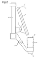
- FIG. 1 the apparatus according to the invention is generally indicated by 1.
- This apparatus comprises a lower frame 2 which can include a weight for stabilizing the arm provided thereon.
- the lower frame is provided with wheels 3 which can optionally be blocked.
- Column 4 extends from the lower frame and arm 5 is swivelable received in upper part of column 4.
- the swivel axis is indicated by 22.
- Arm 5 comprises two arm portions 30 and 31.
- Arm portion 30 is provided with pivot 6 at one extremity thereof and a pivot 7 at the other extremity thereof.
- Arm 31 is provided with pivot 7 and pivot 8. Articulation of pivot 6 is in the direction of arrow 10.
- Pivot 8 comprises a mounting 12 to which a display 13, grip 15 and camera 14 are mounted. Springs and/or other weight balancing means are provided such that in any pivotal position of the pivots 6, 7 and 8 there is not bias for movement of mounting 12 with camera and display.
- any position of the camera/display combination can be made in x, y and z direction.
- Apparatus 1 also comprises an IR source such as an IR led 20 being provided with straps 18 which can be connected to each other through e.g. a Velcro connection.
- This IR source has a finger mounting to receive the IR source on one of the fingers of the observer. The mounting can be connected to the finger in any possible way.
- the above straps are used as example but clipping or a spring connection to the related finger (which can be any finger) could be effected.
- 21 Shows a possible feed for the infrared source 20 but of course a battery operated source can be used.
- the support in which the infrared source is integrated is also possible.
- the IR light used can be any infrared light and is preferably near infra light.
- the infrared source is preferably a LED light source.
- LEDs are used in this example. Those LEDs do not generate substantial heat such the related member to be examined can be firmly pushed there against.
- the diagonal of the LCD display has been indicated by a and is at least 6 cm.
- FIG. 2 shows a detail of mounting 12. It is clear that display 13 is mounted through an articulated connection with mounting 12. This allows for adjustment of the display 13 relative to the mounting 12. However this adjustment is generally only made at taking the position of the observer and after his position has been taken (seated) no further adjustment is necessary.
- the corresponding pivot 34 is provided between grip 15/camera 14 and mounting 12. Also here adjustment is only made before starting the observation procedure. Because the device is directed through grip 15 the friction in pivot 34 to be overcome should be relatively high so that when grip 15 is engaged with a relatively low force mounting 12 will exactly follow. Only if grip 15 is firmly engaged with a tilting movement relative movement can be effected through pivot 34.
- Grip 15 is provided with operating means such as an adjustment mechanism for either focusing camera 14 or adjusting the intensity of the infrared source 20. Further control means may be provided to this end.
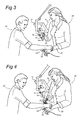
- Figure 3 shows an observer 24 and a patient 23. It is assumed that the hand or arm of the patient has to be punctured. To that end the infrared source 20 is mounted with straps 18 or other means to a finger of the left hand of the observer or in any other position on the hand or arm 28 of the observer 24 and manipulated against the underside of the arm or hand of the patient (arrow 33).
- the right arm 25 are more particular the right hand of the observer 24 is used to manipulate the combination of camera 14 and display 13 above the spot of the extremity of the patient 23 which should be observed. This is effected by engagement of grip 15.
- the distance of the observer 24 to the display is indicated by b and is more than 30 cm.
- the display/camera Once the display/camera is in the correct position the observer no longer engages grip 15. Because of the weight balance nature of arm 5 the display/camera will remain in the last position and the observer can use his right arm/hand to execute the related treatment such as realizing a puncture in a vein or artery.
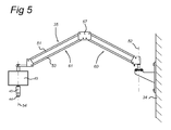
- Figure 5 shows a further embodiment of the invention wherein a different swivel arm 35 is used.
- a weight balanced arm and balancing can be effected through the use of springs (not shown), weight, and/or friction discs.
- Arm 35 is mounted to wall 34.
- Arm 35 comprises arm portions 60 and 61 being connected through a pivot plate 67.
- Each arm portion comprises two parallel arms 51 and 53.
- the structure is such that at displacement of the assembly of camera 44, grip 45 and display 43 axis 54 will always remain parallel to axis 52 around which rotation is possible. Usually this will mean that axis 54 is always substantially vertical and in this way parallax at observation of the related member is prevented as much as possible.
Landscapes
- Health & Medical Sciences (AREA)
- Life Sciences & Earth Sciences (AREA)
- Heart & Thoracic Surgery (AREA)
- Veterinary Medicine (AREA)
- Public Health (AREA)
- General Health & Medical Sciences (AREA)
- Animal Behavior & Ethology (AREA)
- Engineering & Computer Science (AREA)
- Biomedical Technology (AREA)
- Biophysics (AREA)
- Medical Informatics (AREA)
- Molecular Biology (AREA)
- Surgery (AREA)
- Pathology (AREA)
- Physics & Mathematics (AREA)
- Vascular Medicine (AREA)
- Hematology (AREA)
- Dermatology (AREA)
- Anesthesiology (AREA)
- Measurement Of The Respiration, Hearing Ability, Form, And Blood Characteristics Of Living Organisms (AREA)
Abstract
Apparatus and method for determining the position of a vein or artery in a member of a living being. With an IR light source (20), more particular an IR led light source, the related member such as an extremity and more particular a hand, is trans-illuminated. The IR light emerging from the member is scanned with a camera (14) and the image is produced on a display (13) adjacent to the camera. Camera (14) and display (13) are preferably mounted on a manoeuvrable arm (5,35) which can be placed in any desired position relative to the member and observer. Displacement of the camera/display unit can be effected through the presence of a grip to be operated by the hand of the observer. If the quite position is found relative to the member the hand of the observer can be used to execute the related treatment to the vein or artery.
Description
- The present invention relates to an apparatus for determining the position of a vein or artery in a member of a living being, comprising an IR source adapted to be placed at one side of a member of a living being and transferring light through such a member, a camera adapted to be placed at another side of a member of a living being, said other side being opposite to one side of a member of a living being and sensitive for radiation from said IR source, observation means for observing the image of said camera. Such an apparatus is known from
WO 96/36273 - Vessel puncture is a common procedure in daily hospital/health care practice for e.g. blood withdrawal, catheter placement or to administer medicine and fluids. Normally, superficial veins and arteries are visible and easy to access. However, in a significant percentage of patients (up to 20%) the vessels are not visible and the technician or nurse has to rely on indirect signs like tactile feedback, pressure, pulsation or experience. This results in a relative high failure rate to access the vessel at the first and even secondary puncture attempts. This is a painful experience for the patient and inefficient for the procedure. If not successful after several attempts, more experienced professionals like anaesthesiologists need to be called upon, to perform the puncture which is time consuming and uncomfortable for the patient. E.g. various patient groups are notorious for being difficult to puncture: young children with baby fat (age ∼0,5 - 3 years), dark skinned patients and patients with a high body fat index and relatively tiny and deep veins. Since arteries are deeper embedded under the skin, arterial puncture is more difficult in general and needs to be performed with greater care due to the larger arterial pressure leading to complications.
- The problem described is well recognized by the professionals performing the punctures and is extensively describe in literature.
- Transferring light through a member of a living being, or trans-illumination, is for example known from
WO 96/36273 US 6178340 a method for three dimensional infrared imaging of a part of member of a human being on base of reflectance is used. In other words camera and light source are used on the same side of the member to be observed and this results in the impossibility to observe arteries or veins which are somewhat deeper in the related member. - The present invention aims to provide a relatively simple instrument which is easy to use, cheap to produce and improves the procedure of vessel puncture.
- This aim is realized with an apparatus having the features of
claim 1. - In contrast to
WO 96/36273 - It is possible to use cheaply obtained components for the apparatus according to the invention. The light source can comprise an IR led preferably provided with a strap for connecting to the hand or arm of the observer or patient in order to manipulate it in the correct position relative to the member to be observed. The camera can comprise any camera such as a usual CCD camera. The display can comprise any display such as an LCD display.
- According to a preferred embodiment of the invention the display is fixedly connected to the camera in the position of use. More preferable display and camera can be freely manipulated together and to that end they are mounted on the extremity of a swivel arm. After placing the related member in the desired position the combination camera and display can be moved together such as to obtain an optimum image of the member and more particular the arteries and veins thereof. If the required position is reached the observer can take the related measure for example puncturing the artery or vein. More preferable the swivel arm together with camera, display and other auxiliaries is weight balanced i.e. is stable in any position in which it is placed. This means that the observer manipulates the combination of camera and display to the desired position with one hand whilst preferably the other hand is used to manipulate the light source. It is of course possible that the light source is present in a support on which the member such as a hand is laid or connected to the patient. After correctly positioning of the camera/display the observer no longer engages the swivel arm and can use his hand to operate a syringe or other means for treating the related extremity.
- These measures make it possible that in one position of the observer without substantial movement of his head, he is able to both see the display and the place where for example a puncture should be effected. Also the distance between the display and the observer and between the observer and the place to examine (puncture) is such that no substantial refocussing by the observer is necessary when his view is changed from the display to the place to be examined and the member of the living being. In other words only a movement of the eyes of the observer is necessary to go to the place to be examined from the display and vice versa.
- The apparatus according to the invention can be used for example with incubators wherein display and camera can be kept outside the incubator in which a child is present.
- For operation of camera and display mounted to the swivel arm preferably a control grip is provided for engagement by the hand of the observer. If any operating means such as adjusting means for focusing of the camera or controlling the intensity of the light emerging from the infra red source, such control means can be provided on the grip and controlled by a single hand.
- According to a preferred embodiment of the invention the swivel arm is embodied such that the mounting of the camera and display will always have the same orientation (preferably vertical) irrespective of the position of the swivel arm. This can for example be effected by constructing the swivel arm from a number of sub-arms producing a parallelogram structure. In this way parallax can be further avoided.
- The invention also relates to a method for determining the position of a vein or artery in a member of a living being by an observer, comprising trans-illumination of said member with an IR light beam from one side of said member to the other side thereof, scanning said opposite side of said member with an IR sensitive camera and producing a visible image of said camera scanned area, wherein producing of a visible image comprises showing said image on a display spaced at least 30 cm (b) from the eyes of the observer.
- More particular the position of the observer, display and vein or artery in said member, is such that the line of sight of the observer to the display substantially corresponds to the line of sight of the observer to said vein or artery.
- Preferred embodiments of the invention will be further elucidated referring to the enclosed drawings, wherein:
-
Figure 1 shows the general layout of the apparatus according to a first embodiment of the invention; -
Figure 2 shows a detail of positioning of camera and display relative to each other; -
Figure 3 shows the use of an apparatus according to the invention in a first step; -
Figure 4 shows the use of a device in a subsequent step and -
Figure 5 shows schematically a further embodiment of the swivel arm of the invention. - In
Figure 1 the apparatus according to the invention is generally indicated by 1. This apparatus comprises alower frame 2 which can include a weight for stabilizing the arm provided thereon. The lower frame is provided withwheels 3 which can optionally be blocked.Column 4 extends from the lower frame andarm 5 is swivelable received in upper part ofcolumn 4. The swivel axis is indicated by 22.Arm 5 comprises twoarm portions Arm portion 30 is provided withpivot 6 at one extremity thereof and apivot 7 at the other extremity thereof.Arm 31 is provided withpivot 7 andpivot 8. Articulation ofpivot 6 is in the direction ofarrow 10. Articulation ofpivot 7 is in the direction of arrow 9 whilst movement ofpivot 8 is in the direction ofarrow 11.Pivot 8 comprises amounting 12 to which adisplay 13,grip 15 andcamera 14 are mounted. Springs and/or other weight balancing means are provided such that in any pivotal position of thepivots - Through the combination of these
pivots axis 22 any position of the camera/display combination can be made in x, y and z direction. - Of course it is possible not to use a
column 4 but to use anarm 5 connected to a wall, table or other piece of furniture. -
Apparatus 1 also comprises an IR source such as an IR led 20 being provided withstraps 18 which can be connected to each other through e.g. a Velcro connection. This IR source has a finger mounting to receive the IR source on one of the fingers of the observer. The mounting can be connected to the finger in any possible way. The above straps are used as example but clipping or a spring connection to the related finger (which can be any finger) could be effected. 21 Shows a possible feed for theinfrared source 20 but of course a battery operated source can be used. The support in which the infrared source is integrated is also possible. The IR light used can be any infrared light and is preferably near infra light. - For the camera and display easy obtainable components can be used such as a CCD camera and LCD display.
- The infrared source is preferably a LED light source. Four LEDs are used in this example. Those LEDs do not generate substantial heat such the related member to be examined can be firmly pushed there against.
- The diagonal of the LCD display has been indicated by a and is at least 6 cm.
-
Figure 2 shows a detail of mounting 12. It is clear thatdisplay 13 is mounted through an articulated connection with mounting 12. This allows for adjustment of thedisplay 13 relative to the mounting 12. However this adjustment is generally only made at taking the position of the observer and after his position has been taken (seated) no further adjustment is necessary. Thecorresponding pivot 34 is provided betweengrip 15/camera 14 and mounting 12. Also here adjustment is only made before starting the observation procedure. Because the device is directed throughgrip 15 the friction inpivot 34 to be overcome should be relatively high so that whengrip 15 is engaged with a relatively low force mounting 12 will exactly follow. Only ifgrip 15 is firmly engaged with a tilting movement relative movement can be effected throughpivot 34.Grip 15 is provided with operating means such as an adjustment mechanism for either focusingcamera 14 or adjusting the intensity of theinfrared source 20. Further control means may be provided to this end. - From
figure 1 and2 it is clear that through movement ofgrip 15 the combination of camera and display can be put in any position and orientation relative to the observer. - This is further elucidated in
figure 3 and 4. Figure 3 shows anobserver 24 and apatient 23. It is assumed that the hand or arm of the patient has to be punctured. To that end theinfrared source 20 is mounted withstraps 18 or other means to a finger of the left hand of the observer or in any other position on the hand orarm 28 of theobserver 24 and manipulated against the underside of the arm or hand of the patient (arrow 33). Theright arm 25 are more particular the right hand of theobserver 24 is used to manipulate the combination ofcamera 14 anddisplay 13 above the spot of the extremity of the patient 23 which should be observed. This is effected by engagement ofgrip 15. The distance of theobserver 24 to the display is indicated by b and is more than 30 cm. In this way at the same glance the observer can both watch the display and the related spot itself on the arm or hand of thepatient 23. This is indicated infigure 4 wherein the line of sight between the observer and the display is indicated by 30 and the line of sight between the eyes of the observer and the arm to be punctured is indicated by 31. It is clear that only a changed position of the eyes it sufficient to go from the display to the arm and vice versa. - Once the display/camera is in the correct position the observer no longer engages
grip 15. Because of the weight balance nature ofarm 5 the display/camera will remain in the last position and the observer can use his right arm/hand to execute the related treatment such as realizing a puncture in a vein or artery. -
Figure 5 shows a further embodiment of the invention wherein adifferent swivel arm 35 is used. As in the previous example this a weight balanced arm and balancing can be effected through the use of springs (not shown), weight, and/or friction discs.Arm 35 is mounted to wall 34.Arm 35 comprisesarm portions pivot plate 67. Each arm portion comprises twoparallel arms camera 44,grip 45 and display 43 axis 54 will always remain parallel toaxis 52 around which rotation is possible. Usually this will mean that axis 54 is always substantially vertical and in this way parallax at observation of the related member is prevented as much as possible. - It should be realized that the description of the figures relates to a preferred embodiment but after reading the above a person skilled in the art will immediately images further variants which are within the scope of protection of the attended claims.
Claims (17)
- Apparatus (1) for determining the position of a vein or artery in a member of a living being, comprising an IR source (20) adapted to be placed at one side of a member of a living being and transferring light through such a member, a camera (14) adapted to be placed at another side of a member of a living being, said other side being opposite to one side of a member of a living being and sensitive for radiation from said IR source, observation means (13) for observing the image of said camera, characterized in that, said observation means comprise a rectangular display having an effective diagonal of at least 6 cm.
- Apparatus according to claim 1, wherein said display is fixedly connected to said camera in the position of use.
- Apparatus according to one of the preceding claims, comprising a swivel arm (5, 35) wherein said camera and display are mounted to the extremity of said swivel arm.
- Apparatus according to claim 3, wherein said swivel arm is weight balanced.
- Apparatus according to one of the preceding claims, wherein said camera is mounted near said display.
- Apparatus according to one of the preceding claims, wherein said light source comprises an IR led.
- Apparatus according to one of the preceding claims, comprising a control grip (15), wherein the camera (14) and display (13) are mounted to the control grip.
- Apparatus according to one of the preceding claims, wherein the control grip (15) comprises adjustment means (19) for controlling the intensity of the light source and/or the focus of the camera.
- Apparatus according to one of the preceding claims, wherein the IR source comprises a strap (26).
- Apparatus according to one of the preceding claims, wherein the IR source comprises a finger mounting.
- Apparatus according to one of the preceding claims wherein the swivel arm (35) is embodied such that at swivelling the orientation of the camera and display is substantially not changed.
- Method for determining the position of a vein or artery in a member of a living being by an observer, comprising trans-illumination of said member with an IR light beam from one side of said member to the opposite side thereof, scanning said opposite side of said member with an IR sensitive camera and producing a visible image of said camera scanned area, characterized in that, producing of a visible image comprising showing said image on a display (13) spaced at least 30 cm (b) from the eyes of the observer (24).
- Method according to claim 12, wherein said camera and display being freely manoeuverable relative to said member.
- Method according to one of the claims 12 or 13, wherein the position of the observer, display and vein or artery in said member, is such that the line of sight (30) of the observer (24) to the display (13) substantially corresponds to the line of sight (31) of the observer to said vein or artery.
- Method for introducing or removing a substance in/from a vein or artery of a living being, comprising determining the position of said vein or artery according to one of the claims 12-14 engaging a syringe (27) by the observer (24), entering said syringe in said member while simultaneously said member is observed with said IR light.
- Method according to claim 15, wherein said member comprises an extremity.
- Method to one of the claims 12-16, wherein said IR light beam originates from a source which is firmly placed against said member.
Priority Applications (4)
| Application Number | Priority Date | Filing Date | Title |
|---|---|---|---|
| EP08169332A EP2186467A1 (en) | 2008-11-18 | 2008-11-18 | Apparatus and method for determining the position of a vein or artery. |
| EP09760342A EP2375965A1 (en) | 2008-11-18 | 2009-11-18 | Apparatus and method for determining the position of a vein or artery |
| US13/129,984 US20110313294A1 (en) | 2008-11-18 | 2009-11-18 | Apparatus and method for determining the position of a vein or artery |
| PCT/NL2009/050695 WO2010059045A1 (en) | 2008-11-18 | 2009-11-18 | Apparatus and method for determining the position of a vein or artery |
Applications Claiming Priority (1)
| Application Number | Priority Date | Filing Date | Title |
|---|---|---|---|
| EP08169332A EP2186467A1 (en) | 2008-11-18 | 2008-11-18 | Apparatus and method for determining the position of a vein or artery. |
Publications (1)
| Publication Number | Publication Date |
|---|---|
| EP2186467A1 true EP2186467A1 (en) | 2010-05-19 |
Family
ID=40297940
Family Applications (2)
| Application Number | Title | Priority Date | Filing Date |
|---|---|---|---|
| EP08169332A Ceased EP2186467A1 (en) | 2008-11-18 | 2008-11-18 | Apparatus and method for determining the position of a vein or artery. |
| EP09760342A Ceased EP2375965A1 (en) | 2008-11-18 | 2009-11-18 | Apparatus and method for determining the position of a vein or artery |
Family Applications After (1)
| Application Number | Title | Priority Date | Filing Date |
|---|---|---|---|
| EP09760342A Ceased EP2375965A1 (en) | 2008-11-18 | 2009-11-18 | Apparatus and method for determining the position of a vein or artery |
Country Status (3)
| Country | Link |
|---|---|
| US (1) | US20110313294A1 (en) |
| EP (2) | EP2186467A1 (en) |
| WO (1) | WO2010059045A1 (en) |
Cited By (7)
| Publication number | Priority date | Publication date | Assignee | Title |
|---|---|---|---|---|
| CN102872491A (en) * | 2012-09-29 | 2013-01-16 | 青岛光电医疗科技有限公司 | Medical observation lamp for foot veins |
| CN103239213A (en) * | 2013-05-14 | 2013-08-14 | 徐志强 | Observation device for auxiliary observation of venipuncture |
| CN103239212A (en) * | 2013-05-14 | 2013-08-14 | 徐志强 | Vein observation device capable of reducing heat emitting of light emitting tube |
| CN103505182A (en) * | 2013-09-17 | 2014-01-15 | 周红仙 | Positioning device and positioning method of handheld imaging system |
| CN104739370A (en) * | 2013-12-31 | 2015-07-01 | 环达电脑(上海)有限公司 | Electronic device with blood vessel identifying and positioning functions and blood vessel identifying and positioning method |
| CN107715259A (en) * | 2017-11-23 | 2018-02-23 | 杨琨 | Puncture servicing unit and its operating method based on angle recognition technology |
| CN110464307A (en) * | 2019-08-22 | 2019-11-19 | 湖南丹尼尔智能科技有限公司 | A kind of auxiliary device convenient for being quickly found out vein blood vessel acupuncture treatment |
Families Citing this family (9)
| Publication number | Priority date | Publication date | Assignee | Title |
|---|---|---|---|---|
| US20130295518A1 (en) * | 2012-03-29 | 2013-11-07 | William S. Parker | Apparatus and Method for Achieving a Head Up Posture for a 3-D Video Image for Operative Procedures in Dentistry |
| CN103222855B (en) * | 2013-04-02 | 2015-04-22 | 徐志强 | Medical auxiliary observation device |
| JP6381098B2 (en) * | 2013-10-09 | 2018-08-29 | 株式会社オカムラ | Support device |
| CN106461171B (en) * | 2014-05-09 | 2019-07-30 | 伦斯莱尔工艺研究院 | For adjusting baby's circadian rhythm and providing the NICU insulating box light emitting top of baby's anatomy high-visibility to medical staff |
| WO2016033590A1 (en) | 2014-08-31 | 2016-03-03 | Berestka John | Systems and methods for analyzing the eye |
| CN106823045B (en) * | 2017-03-29 | 2023-02-17 | 泉州医学高等专科学校 | Auxiliary amplification device for venipuncture |
| JP7116979B2 (en) * | 2017-08-02 | 2022-08-12 | 株式会社テクノメデイカ | Blood collection work assistance system |
| DE102019134329B4 (en) * | 2019-12-13 | 2021-11-25 | Carl Zeiss Meditec Ag | Suspension for digital surgical microscope with position correction, optical device and procedure for its operation |
| CN112515638A (en) * | 2020-12-02 | 2021-03-19 | 杭州医学院 | Vein blood vessel imaging instrument |
Citations (7)
| Publication number | Priority date | Publication date | Assignee | Title |
|---|---|---|---|---|
| WO1994015531A1 (en) * | 1993-01-18 | 1994-07-21 | The State Of Israel | Infra-red vascular angiography system |
| WO1996036273A2 (en) | 1995-05-16 | 1996-11-21 | The United States Of America, Represented By The Secretary Of The Air Force | System and method for enhanced visualization of subcutaneous structures |
| US6178340B1 (en) | 1998-08-24 | 2001-01-23 | Eduardo Svetliza | Three-dimensional infrared imager for subcutaneous puncture and study of vascular network |
| US6424858B1 (en) * | 1998-11-12 | 2002-07-23 | John L. Williams | Apparatus and method for viewing vasculature of a human being |
| US20040171923A1 (en) * | 2002-12-06 | 2004-09-02 | Kalafut John F. | Devices, systems and methods for improving vessel access |
| WO2007016048A2 (en) * | 2005-07-27 | 2007-02-08 | University Of Massachusetts Lowell | Infrared scanner for biological applications |
| WO2008044697A1 (en) * | 2006-10-11 | 2008-04-17 | Panasonic Electric Works Co., Ltd. | Device for acquiring vein pattern |
Family Cites Families (8)
| Publication number | Priority date | Publication date | Assignee | Title |
|---|---|---|---|---|
| US4817622A (en) * | 1986-07-22 | 1989-04-04 | Carl Pennypacker | Infrared imager for viewing subcutaneous location of vascular structures and method of use |
| JPS63296743A (en) * | 1987-05-29 | 1988-12-02 | Mitaka Koki Kk | Stand apparatus for medical optical machinery |
| US5608210A (en) * | 1994-09-29 | 1997-03-04 | Esparza; Joel | Infrared aided method and apparatus for venous examination |
| US6889075B2 (en) * | 2000-05-03 | 2005-05-03 | Rocky Mountain Biosystems, Inc. | Optical imaging of subsurface anatomical structures and biomolecules |
| US6902290B2 (en) * | 2002-08-02 | 2005-06-07 | R & H Industries, Inc. | Finger-mounted light for variable light output |
| US7532746B2 (en) * | 2004-01-16 | 2009-05-12 | Vue Tek Scientific, Llc | System and method for locating and accessing a blood vessel |
| WO2007115570A1 (en) * | 2006-04-07 | 2007-10-18 | Novarix Ltd | Vein navigation device |
| US20080194930A1 (en) * | 2007-02-09 | 2008-08-14 | Harris Melvyn L | Infrared-visible needle |
-
2008
- 2008-11-18 EP EP08169332A patent/EP2186467A1/en not_active Ceased
-
2009
- 2009-11-18 US US13/129,984 patent/US20110313294A1/en not_active Abandoned
- 2009-11-18 EP EP09760342A patent/EP2375965A1/en not_active Ceased
- 2009-11-18 WO PCT/NL2009/050695 patent/WO2010059045A1/en active Application Filing
Patent Citations (7)
| Publication number | Priority date | Publication date | Assignee | Title |
|---|---|---|---|---|
| WO1994015531A1 (en) * | 1993-01-18 | 1994-07-21 | The State Of Israel | Infra-red vascular angiography system |
| WO1996036273A2 (en) | 1995-05-16 | 1996-11-21 | The United States Of America, Represented By The Secretary Of The Air Force | System and method for enhanced visualization of subcutaneous structures |
| US6178340B1 (en) | 1998-08-24 | 2001-01-23 | Eduardo Svetliza | Three-dimensional infrared imager for subcutaneous puncture and study of vascular network |
| US6424858B1 (en) * | 1998-11-12 | 2002-07-23 | John L. Williams | Apparatus and method for viewing vasculature of a human being |
| US20040171923A1 (en) * | 2002-12-06 | 2004-09-02 | Kalafut John F. | Devices, systems and methods for improving vessel access |
| WO2007016048A2 (en) * | 2005-07-27 | 2007-02-08 | University Of Massachusetts Lowell | Infrared scanner for biological applications |
| WO2008044697A1 (en) * | 2006-10-11 | 2008-04-17 | Panasonic Electric Works Co., Ltd. | Device for acquiring vein pattern |
Cited By (10)
| Publication number | Priority date | Publication date | Assignee | Title |
|---|---|---|---|---|
| CN102872491A (en) * | 2012-09-29 | 2013-01-16 | 青岛光电医疗科技有限公司 | Medical observation lamp for foot veins |
| CN103239213A (en) * | 2013-05-14 | 2013-08-14 | 徐志强 | Observation device for auxiliary observation of venipuncture |
| CN103239212A (en) * | 2013-05-14 | 2013-08-14 | 徐志强 | Vein observation device capable of reducing heat emitting of light emitting tube |
| CN103239212B (en) * | 2013-05-14 | 2014-12-03 | 李娜 | Vein observation device capable of reducing heat emitting of light emitting tube |
| CN103239213B (en) * | 2013-05-14 | 2015-01-07 | 徐志强 | Observation device for auxiliary observation of venipuncture |
| CN103505182A (en) * | 2013-09-17 | 2014-01-15 | 周红仙 | Positioning device and positioning method of handheld imaging system |
| CN103505182B (en) * | 2013-09-17 | 2015-07-08 | 周红仙 | Positioning device and positioning method of handheld imaging system |
| CN104739370A (en) * | 2013-12-31 | 2015-07-01 | 环达电脑(上海)有限公司 | Electronic device with blood vessel identifying and positioning functions and blood vessel identifying and positioning method |
| CN107715259A (en) * | 2017-11-23 | 2018-02-23 | 杨琨 | Puncture servicing unit and its operating method based on angle recognition technology |
| CN110464307A (en) * | 2019-08-22 | 2019-11-19 | 湖南丹尼尔智能科技有限公司 | A kind of auxiliary device convenient for being quickly found out vein blood vessel acupuncture treatment |
Also Published As
| Publication number | Publication date |
|---|---|
| WO2010059045A1 (en) | 2010-05-27 |
| US20110313294A1 (en) | 2011-12-22 |
| EP2375965A1 (en) | 2011-10-19 |
Similar Documents
| Publication | Publication Date | Title |
|---|---|---|
| EP2186467A1 (en) | Apparatus and method for determining the position of a vein or artery. | |
| EP1841361B1 (en) | System for inserting a needle into a blood vessel | |
| US7532746B2 (en) | System and method for locating and accessing a blood vessel | |
| JP5756161B2 (en) | Retractor | |
| US20210220059A1 (en) | Anatomical Attachment Device and Associated Method of Use | |
| US6463309B1 (en) | Apparatus and method for locating vessels in a living body | |
| US20040015158A1 (en) | Transilluminator device | |
| US20150327765A1 (en) | Apparatus and method for imaging vasculature and sub-dermal structures by trans-illuminating nir light | |
| JP6047847B1 (en) | Arterial visualization device | |
| WO2008081438A1 (en) | Vascular access system and method | |
| CN111511268A (en) | Retinal imaging device and associated method | |
| AU2012327343A1 (en) | Telescopic retractor holder | |
| CN106491076A (en) | Full-automatic fundus camera | |
| EP3586727B1 (en) | Vein detection device | |
| US20180028058A1 (en) | Device for supporting an image-capturing apparatus for medical examination and method | |
| CN102973322B (en) | Palm rest fixing support for radial artery puncture | |
| CN204106149U (en) | Venipuncture inducer | |
| US20200324061A1 (en) | Transilluminating Immobilizer for Intravenous and Intra-arterial procedures | |
| CN208524846U (en) | Wearable vein visible instrument | |
| CN213606395U (en) | Miniature visual artery blood sampling device | |
| CN215348878U (en) | Auxiliary fixing device for eye examination | |
| CN213430861U (en) | Neck support | |
| CN115120200A (en) | Puncture auxiliary glasses and control method thereof | |
| CN206063133U (en) | Arterography venography device | |
| WO2009023656A2 (en) | Vasculature visualization apparatus |
Legal Events
| Date | Code | Title | Description |
|---|---|---|---|
| PUAI | Public reference made under article 153(3) epc to a published international application that has entered the european phase |
Free format text: ORIGINAL CODE: 0009012 |
|
| AK | Designated contracting states |
Kind code of ref document: A1 Designated state(s): AT BE BG CH CY CZ DE DK EE ES FI FR GB GR HR HU IE IS IT LI LT LU LV MC MT NL NO PL PT RO SE SI SK TR |
|
| AX | Request for extension of the european patent |
Extension state: AL BA MK RS |
|
| STAA | Information on the status of an ep patent application or granted ep patent |
Free format text: STATUS: THE APPLICATION HAS BEEN REFUSED |
|
| 18R | Application refused |
Effective date: 20100710 |