EP2186107B1 - Circuit breaker with high speed mechanically-interlocked grounding switch - Google Patents
Circuit breaker with high speed mechanically-interlocked grounding switch Download PDFInfo
- Publication number
- EP2186107B1 EP2186107B1 EP08871526.3A EP08871526A EP2186107B1 EP 2186107 B1 EP2186107 B1 EP 2186107B1 EP 08871526 A EP08871526 A EP 08871526A EP 2186107 B1 EP2186107 B1 EP 2186107B1
- Authority
- EP
- European Patent Office
- Prior art keywords
- contact
- circuit breaker
- bushing
- vacuum bottle
- vacuum
- Prior art date
- Legal status (The legal status is an assumption and is not a legal conclusion. Google has not performed a legal analysis and makes no representation as to the accuracy of the status listed.)
- Active
Links
- 239000004020 conductor Substances 0.000 description 7
- 239000002184 metal Substances 0.000 description 7
- 230000007246 mechanism Effects 0.000 description 4
- 230000001052 transient effect Effects 0.000 description 4
- 238000004804 winding Methods 0.000 description 4
- 230000033001 locomotion Effects 0.000 description 3
- 238000002844 melting Methods 0.000 description 3
- 230000008018 melting Effects 0.000 description 3
- 238000010586 diagram Methods 0.000 description 2
- 238000002474 experimental method Methods 0.000 description 2
- 239000002245 particle Substances 0.000 description 2
- 230000005540 biological transmission Effects 0.000 description 1
- 238000004891 communication Methods 0.000 description 1
- 238000010276 construction Methods 0.000 description 1
- 230000001066 destructive effect Effects 0.000 description 1
- 238000001514 detection method Methods 0.000 description 1
- 230000000694 effects Effects 0.000 description 1
- 238000010891 electric arc Methods 0.000 description 1
- 230000005611 electricity Effects 0.000 description 1
- 238000009434 installation Methods 0.000 description 1
- 238000004519 manufacturing process Methods 0.000 description 1
- 238000000034 method Methods 0.000 description 1
- 230000001681 protective effect Effects 0.000 description 1
- 238000010791 quenching Methods 0.000 description 1
- 238000011084 recovery Methods 0.000 description 1
- 238000000926 separation method Methods 0.000 description 1
- 239000007787 solid Substances 0.000 description 1
Images


Classifications
-
- H—ELECTRICITY
- H01—ELECTRIC ELEMENTS
- H01H—ELECTRIC SWITCHES; RELAYS; SELECTORS; EMERGENCY PROTECTIVE DEVICES
- H01H31/00—Air-break switches for high tension without arc-extinguishing or arc-preventing means
- H01H31/003—Earthing switches
-
- H—ELECTRICITY
- H01—ELECTRIC ELEMENTS
- H01H—ELECTRIC SWITCHES; RELAYS; SELECTORS; EMERGENCY PROTECTIVE DEVICES
- H01H33/00—High-tension or heavy-current switches with arc-extinguishing or arc-preventing means
- H01H33/60—Switches wherein the means for extinguishing or preventing the arc do not include separate means for obtaining or increasing flow of arc-extinguishing fluid
- H01H33/66—Vacuum switches
- H01H33/666—Operating arrangements
- H01H2033/6667—Details concerning lever type driving rod arrangements
Definitions
- these wind turbines can each produce between 500 kW and 3500 kW of power.
- the outputs of generators in the wind farm are often grouped into several electrical collection circuits. Transformers are used so as to tie the wind turbine output the conductors to the 34.5 kV collection circuits.
- the transformers serve to step up the output voltage of the wind energy generators to a medium voltage, usually 34.5 kilovolts.
- the various wind turbines in a wind farm are usually paralleled into collection circuits that can deliver 15 to 30 megawatts of power. In view of the voltage which has been stepped up to the 34.5 kilovolts, each collection circuit will require a circuit breaker rated at a minimum 34.5 kilovolts capacity.
- the energy will pass through the circuit breaker to the 34.5 kV bus of a substation.
- the 34.5 kV substation bus will go into one or more main step-up transformers and then tie into a high voltage utility line.
- a need has developed so as to provide a circuit breaker that can tie collection circuits into the 34.5 kV substation bus.
- Such a circuit breaker should be of low cost, weatherproof, and able to effectively break the current in the event of a problem condition.
- the actuator arm is interconnected to a supply of power.
- a power supply is connected by a line to the actuator arm.
- a substation is connected by a line to the first contact of the first vacuum bottle. Power is passed from the power supply to the substation when the actuator arm is in the first position.
- the power supply has a three phase current.
- the first vacuum bottle includes three vacuum bottles and the second vacuum bottle comprises three vacuum bottles. The first contact in each of the three vacuum bottles is connected to a separate phase of the power supply.
- the actuator arm is electrically interconnected to a first bushing.
- the first contact of the first vacuum bottle is connected to a second bushing.
- the first bushing is connected to the power supply while the second bushing is connected to the substation.
- At least one first current transformer extends around the first bushing.
- a second current transformer extends around the second bushing.
- the power supply will have a nominal voltage of 34.5 kilovolts or lower.
- the bushing 80 has another current transformer 84 extending therearound.
- Current transformer 84 is a configuration similar to that of current transformer 82.
- Current transformer 84 serves to sense the power, and the quality of power passing outwardly of the circuit breaker 44 and to the substation.
- the current transformer 84 can be suitably interconnected to proper relays so as to open and close the circuit breaker 44 in the event of a problem condition.
- a door 118 is mounted on the housing 74 so as to allow easy access to the interior of the housing 74.
- Legs 110 serve to support the housing 74 above the earth.
- a variety of techniques can be utilized for moving the actuator arm 120 between the first and second position.
- latches, springs, magnets, or other devices can be employed so as to instantaneously shift the actuator arm 120 between the first and second positions.
- the vertical alignment of the first vacuum bottle 90 with the second vacuum bottle 92 assures that this mechanical connection instantaneously serves to transfer energy.
- the present invention avoids the need for electrical interconnections. Experiments with the system of the present invention have indicated that the switching can occur in less than one cycle.
Landscapes
- Gas-Insulated Switchgears (AREA)
- Wind Motors (AREA)
- High-Tension Arc-Extinguishing Switches Without Spraying Means (AREA)
Description
- The present invention relates to vacuum circuit breakers. More particularly, the present invention relates to circuit breakers having a mechanically interlocked grounding switch. Additionally, the present invention relates to circuit breakers for use in association with wind farm collection circuits.
- Wind farms are becoming increasing popular for the generation of electricity. In a wind farm, there are a large number of wind energy generators installed in locations of the country where wind is consistent and substantial. Typically, the wind energy generators will include an array of blades that are coupled to a shaft. The rotation of the shaft caused by the rotation of the blades will produce electrical energy. Electrical lines will connect with the energy generator so as to deliver the energy from a particular wind energy generator to a collection bus. The electrical energy from the various wind energy generators in the wind farm can collectively pass energy to a substation.
- Typically, these wind turbines can each produce between 500 kW and 3500 kW of power. The outputs of generators in the wind farm are often grouped into several electrical collection circuits. Transformers are used so as to tie the wind turbine output the conductors to the 34.5 kV collection circuits. The transformers serve to step up the output voltage of the wind energy generators to a medium voltage, usually 34.5 kilovolts. The various wind turbines in a wind farm are usually paralleled into collection circuits that can deliver 15 to 30 megawatts of power. In view of the voltage which has been stepped up to the 34.5 kilovolts, each collection circuit will require a circuit breaker rated at a minimum 34.5 kilovolts capacity. The energy will pass through the circuit breaker to the 34.5 kV bus of a substation. The 34.5 kV substation bus will go into one or more main step-up transformers and then tie into a high voltage utility line. As such, a need has developed so as to provide a circuit breaker that can tie collection circuits into the 34.5 kV substation bus. Such a circuit breaker should be of low cost, weatherproof, and able to effectively break the current in the event of a problem condition.
- Typically, with circuit breakers, the circuit to the substation can be broken upon the application of a manual force to a button or lever of the circuit breaker or by an automatic relay which opens the circuit. Typically, the current is measured to the substation. If any relay senses a problem, then a signal is transmitted to the circuit breaker so as to open the breaker. Typically, the relays will be maintained within the substation. The opening of the circuit breaker will prevent the energy from being continued to be transmitted to the substation. Sometimes, the circuit breaker is open so as to allow users to work on the wind farm system, on the circuit breaker, or on the substation. Typically, the relays will operate if the sensors sense a voltage drop.
- The interruption of electrical power circuits has always been an essential function, especially in cases of overloads or short circuits, when immediate interruption of the current flow becomes necessary as a protective measure. In earliest times, circuits could be broken only by separation of contacts in air followed by drawing the resulting electric arc out to such a length that it can no longer be maintained. This means of interruption soon became inadequate and special devices, termed "circuit breakers", were developed. The basic problem is to control and quench the high power arc. This necessarily occurs at the separating contacts of a breaker when opening high current circuits. Since arcs generate a great deal of heat energy which is often destructive to the breaker's contacts, it is necessary to limit the duration of the arc and to develop contacts that can withstand the effect of the arc time after time.
- A vacuum circuit breaker uses the rapid dielectric recovery and high dielectric strength of the vacuum. The pair of contacts are hermetically sealed in the vacuum envelope. An actuating motion is transmitted through bellows to the movable contact. When the electrodes are parted, an arc is produced and supported by metallic vapor boiled from the electrodes. Vapor particles expand into the vacuum and condense on solid surfaces. At a natural current zero the vapor particles disappear and the arc is extinguished.
- In the past, various patents have issued relating to such vacuum circuit breakers. For example,
U.S. Patent No. 5,612,523, issued on March 18, 1997 to Hakamata et al. , teaches a vacuum circuit-breaker and electrode assembly. A portion of a highly conductive metal member is infiltrated in voids of a porous high melting point metal member. Both of the metal members are integrally joined to each other. An arc electrode portion is formed of a high melting point area in which the highly conductive metal is infiltrated in voids of the high melting point metal member. A coil electrode portion is formed by hollowing out the interior of a highly conductive metal area composed only of the highly conductive metal and by forming slits thereon. A rod is brazed on the rear surface of the coil electrode portion. -
U.S. Patent No. 6,048,216, issued on April 11, 2000 to Komuro , describes a vacuum circuit breaker having a fixed electrode and a movable electrode. An arc electrode support member serves to support the arc electrode. A coil electrode is contiguous to the arc electrode support member. This vacuum circuit breaker is a highly reliable electrode of high strength which will undergoes little change with the lapse of time. -
U.S. Patent No. 6,759,617, issued on July 6, 2004 to S.J. Yoon , describes a vacuum circuit breaker having a plurality of switching mechanisms with movable contacts and stationary contacts for connecting/breaking an electrical circuit between an electric source and an electric load. The actuator unit includes at least one rotary shaft for providing the movable contacts with dynamic power so as to move to positions contacting the stationary contacts or positions separating from the stationary contacts. A supporting frame fixes and supports the switching mechanism units and the actuator unit. A transfer link unit is used to transfer the rotating movement of the rotary shaft to a plurality of vertical movements. -
U.S. Patent No. 7,223,923, issued on May 28, 2007 to Kobayashi et al. , provides a vacuum switchgear. This vacuum switchgear includes an electro-conductive outer vacuum container and a plurality of inner containers disposed in the outer vacuum container. The inner containers and the outer container are electrically isolated from each other. One of the inner vacuum containers accommodates a ground switch for keeping the circuit open while the switchgear is opened. A movable electrode is connected to an operating mechanism and a fixed electrode connected to a fixed electrode rod. Another inner vacuum container accommodates a function switch capable of having at least one of the functions of a circuit breaker, a disconnector and a load switch. -
JP 11 162303 A - In the past, in association with such wind farms, when collect circuit breakers are opened, the collection circuit voltage would be interrupted and a transient overvoltage situation could occur in the collection circuit. In the over voltage situation, the high transient voltage in the collection circuit line will "back up" through the circuit and to the electronics associated with the wind energy generators. As a result, this transient overvoltage could cause damage to the circuitry associated with the wind energy generators and other circuitry throughout the system. As a result, in view of the characteristics of the large energy resident within by the overall wind energy farm, there is an extreme need to hold within acceptable limits any overvoltage which occurs when the circuit breaker is be opened.
- Typically, to avoid the over voltage situation, grounding transformers have been required to be installed. These grounding transformers would typically have 34.5 kilovolts on the primary winding with a 600 volts open delta secondary winding. The transformer has a core with windings therearound. In view of the core and windings, there was continuous amount of core losses of energy associated with the use of such grounding transformers. Over time, the core losses could amount to a significant dollar amount of lost energy. Additionally, these grounding transformers had a relatively high initial cost, installation cost, and a long lead time of delivery.
-
FIGURE 1 is an illustration of a prior art system employing a ground transformer. As can be seen,wind power generators respective lines bus 26 via step-up transformers 17, 19, 21 and 23. Thebus 26 has aswitch 28 located therealong. The groundingtransformer 30 is connected forwardly of theswitch 28. When theswitch 28 is opened, as illustrated inFIGURE 1 , the energy along thebus 26 is passed to theground transformer 30 and to ground. When theswitch 28 is closed, the energy from thebus 26 is passed along anotherbus 32 for passage to thecircuit breaker 34 and then alongline 36 to thesubstation 38. When theground transformer 30 is effectively used, then any over voltages are immediately transferred to ground in an acceptable manner. As can be seen inFIGURE 1 , when thecircuit breaker 34 is activated so as to open the circuit, a signal can be passed alongline 40 to theswitch 28 so as to open theswitch 28 and to cause the energy in thebus 26 to pass to theground transformer 30. - When ground transformers are not used, it is necessary to switch the circuit to ground extremely quickly. If the switch does not occur within a maximum of three cycles, then the overvoltage condition can occur. Ideally, to avoid any potential for an overvoltage situation, it is necessary to close the circuit to ground within one cycle, i.e. 16 milliseconds. Ultimately, experiments in attempting to achieve electrical switching systems indicated that the switching would occur at a level dangerously close to the five cycle limit. Preferably, it is desirable to cause the switching to occur in as close to an instantaneous manner as possible.
- It is an object of the present invention to provide a vacuum circuit breaker with an integral high speed grounding switch of a relatively low cost.
- It is another object of the present invention to provide a vacuum circuit breaker with an integral high speed grounding switch that is weatherproof.
- It is a further object of the present invention to provide a vacuum circuit breaker with an integral high speed grounding switch which eliminates the need for ground transformers.
- It is a further object of the present invention to provide a vacuum circuit breaker with an integral high speed grounding switch which minimizes energy losses.
- It is still a further object of the present invention to provide a vacuum circuit breaker with an integral high speed grounding switch that closes the circuit to ground virtually instantaneously.
- It is still a further object of the present invention to provide a vacuum circuit breaker with an integral high speed grounding switch that can be operated in the range of 34.5 kilovolts.
- It is still another object of the present invention to provide a vacuum circuit breaker that is effective for use in association with wind farm energy production.
- These and other objects and advantages of the present invention will become apparent from a reading of the attached specification and appended claims.
- The present invention provides a circuit breaker apparatus according to
claim 1. - An actuator serves to move the mechanical linkage between the first position and the second position. The first vacuum bottle is in longitudinal alignment with the second vacuum bottle. The mechanical linkage is interposed between the first and second vacuum bottles.
- The mechanical linkage comprises an actuator arm having the other of the pair of contacts of the first vacuum bottle electrically connected thereto. The actuator arm has the other of the pair of contacts of the second vacuum bottle electrically connected thereto. The pair of contacts of the first vacuum bottle being electrically connected together when in the first position. The pair of contacts of the first vacuum bottle are electrically isolated from each other in the second position. The pair of contacts of second vacuum bottle are electrically isolated from each other in the first position. The pair of contacts of the second vacuum bottle are electrically connected together in the second position.
- The actuator arm is interconnected to a supply of power. In particular, a power supply is connected by a line to the actuator arm. A substation is connected by a line to the first contact of the first vacuum bottle. Power is passed from the power supply to the substation when the actuator arm is in the first position. The power supply has a three phase current. As such, the first vacuum bottle includes three vacuum bottles and the second vacuum bottle comprises three vacuum bottles. The first contact in each of the three vacuum bottles is connected to a separate phase of the power supply. The actuator arm is electrically interconnected to a first bushing. The first contact of the first vacuum bottle is connected to a second bushing. The first bushing is connected to the power supply while the second bushing is connected to the substation. At least one first current transformer extends around the first bushing. A second current transformer extends around the second bushing. The power supply will have a nominal voltage of 34.5 kilovolts or lower.
- The present invention can be used in a system for passing energy from a power supply to substation. This system comprises a bus suitable for passing energy from the power supply, a line connected to ground, a circuit suitable for passing energy from the bus to the substation, and a circuit beaker interconnected between a contact of the bus and a contact of the line and a contact of the circuit. The circuit breaker has means for mechanically and selectively connecting the contact of the bus to the contact of the circuit and for connecting the contact of the bus to the contact for the line. The first vacuum bottle has the contact for the bus and the contact for the circuit therein. The second vacuum bottle has the contact for the line therein. The mechanical interlock extends between the first and second vacuum bottles and is electrically interconnected to the bus. The plurality of wind energy generators are connected to the bus.
-
-
FIGURE 1 is a block diagram showing the operation of a prior art circuit breaker system. -
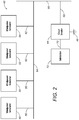
FIGURE 2 is a block diagram showing the circuit breaker system of the present invention. -
FIGURE 3 is a side interior view of the circuit breaker of the preferred embodiment of the present invention. -
FIGURE 4 is a frontal elevation of the circuit breaker of the preferred embodiment present invention. -
FIGURE 5 is an illustration of the mechanical interlock of the present invention in combination of the first and second vacuum bottles with the mechanical interlock in the first position. -
FIGURE 6 is an illustration of the operation of the mechanical interlock of the present invention with the mechanical interlock in a second position. -
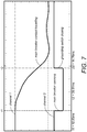
FIGURE 7 is a graph showing the switch operation of the circuit breaker of the present invention. - Referring to
FIGURE 2 , there is shown thesystem 42 of the present invention. Thecircuit breaker system 42 of the present invention includes thecircuit breaker apparatus 44 as used for transferring energy upon the opening of the circuit to ground 46. A plurality ofwind energy generators respective conductors bus 64. Thewind energy generators various busses 64 can also be connected to a mainenergy transfer bus 66. Ultimately, the energy is transmitted alongline 68 to thecircuit breaker 44. When thecircuit breaker 44 is suitably closed, then the energy will be delivered alongline 70 tosubstation 72. It can be seen inFIGURE 2 that thebus 64 does not include the groundingtransformer 30 of the prior art. As such, it is the goal of the circuit breaker 44 (with grounding switch) to switch the energy to ground 46 as quickly as possible, preferably, within one cycle (i.e., within 16 milliseconds). -
FIGURE 3 shows thecircuit breaker 44 of the present invention.Circuit breaker 44 includes ahousing 74 having aweather proof roof 76 extending thereover. Afirst bushing 78 and asecond bushing 80 extend outwardly of thehousing 74 and through theroof 76.Bushing 78 will extend to the wind farm side of the circuit.Bushing 80 will extend to the substation side of the circuit. A firstcurrent transformer 82 is positioned over thebushing 78. Thecurrent transformer 82 is a doughnut-shaped transformer which serves to detect the amount of current passing through thefirst bushing 78. As such, thecurrent transformer 82 serves to monitor the power, and the quality of power passing throughbushing 78. Thecurrent transformer 82 can be electrically interconnected to a suitable relay for opening and closing the circuit breaker in the event of the detection of a problem with the power transmission, or other requirements of the opening or closing of the circuit breaker. - The
bushing 80 has anothercurrent transformer 84 extending therearound.Current transformer 84 is a configuration similar to that ofcurrent transformer 82.Current transformer 84 serves to sense the power, and the quality of power passing outwardly of thecircuit breaker 44 and to the substation. Once again, thecurrent transformer 84 can be suitably interconnected to proper relays so as to open and close thecircuit breaker 44 in the event of a problem condition. - A
busbar 86 connects thebushing 78 to themechanical interlock 88. Themechanical interlock 88 is interposed between afirst vacuum bottle 90 and asecond vacuum bottle 92. Anotherbusbar 94 is located at the top of thefirst vacuum bottle 90 and extends in electrical connection to thesecond bushing 80. Thesecond vacuum bottle 92 includes a groundingbar 96 suitably connected to ground.Supports vacuum bottles mechanical interlock 88, in a longitudinally aligned orientation extending substantially vertically within the interior of thehousing 74. A suitable operating andcommunication mechanism 104 is cooperative with themechanical interlock 88. Control push buttons and indicatinglamps 106 are located on a wall of theenclosure 74 so as to provide a humanly perceivable indication of the operation of thecircuit breaker 44 and allowing for manual control of themechanical interlock 88. There is an auxiliaryterminal block compartment 108 located on an opposite wall of theenclosure 74 from thecontrol push buttons 106. Thehousing 74 is supported above the earth by legs 110 (or by other means). -
FIGURE 4 shows a frontal view of thehousing 74 of thecircuit breaker 44. Importantly, inFIGURE 4 , it can be seen that thebushing 78 actually includes afirst bushing 112, a second bushing 114 and athird bushing 116 extending outwardly of theroof 76 ofhousing 74. Thebushings second bushing 80 will also have an array of three of such bushings such that the three phases can be passed from the circuit breaker. - A
door 118 is mounted on thehousing 74 so as to allow easy access to the interior of thehousing 74.Legs 110 serve to support thehousing 74 above the earth. -
FIGURE 5 illustrates the operation of themechanical interlock 88 of the present invention. As can be seen, themechanical interlock 88 includes anactuator arm 120 which extends between thefirst vacuum bottle 90 and thesecond vacuum bottle 92. Thebusbar 86 is electrically interconnected to theactuator arm 120. - The
first vacuum bottle 90 is hermetically sealed in a vacuum condition. Thefirst vacuum bottle 90 includes afirst contact 122 and asecond contact 124 within the interior of thevacuum bottle 90. Thefirst contact 122 is connected byconductor 126 in electrical interconnection to thesecond bushing 80. Thesecond vacuum bottle 92 includes afirst contact 128 and asecond contact 130. Thesecond contact 130 is connected byconductor 132 toground 46. - In
FIGURE 5 , theactuator arm 120 is in its first position. In this position, thecontacts busbar 86 will be transmitted through the interior of thefirst vacuum bottle 90 throughconductor 126 to thebushing 80. The circuit to ground through thesecond vacuum bottle 92 is open. As such,FIGURE 5 illustrates the normal operating condition of thecircuit breaker 44 of the present invention in which the power is passed directly therethrough to thesubstation 72. - In the event of an interruption, a failure, or a problem, the
circuit breaker 44 will open the circuit to the substation so that the electrical energy passing through thebusbar 86 is passed to ground 46 instantaneously. As can be seen inFIGURE 6 , thefirst contact 122 is electrically isolated from thesecond contact 124 within the interior ofvacuum bottle 90. As such, theconductor 126 is electrically isolated from power passing from thebusbar 86. Theactuator arm 120 instantaneously separates thecontact 124 from thecontact 122 while, at the same time, establishes an electrical connection between thecontact 128 and thecontact 130 in thesecond vacuum bottle 92. As such, the power from thebusbar 86 is immediately switched toground 46. - A variety of techniques can be utilized for moving the
actuator arm 120 between the first and second position. For example, latches, springs, magnets, or other devices can be employed so as to instantaneously shift theactuator arm 120 between the first and second positions. Importantly, the vertical alignment of thefirst vacuum bottle 90 with thesecond vacuum bottle 92 assures that this mechanical connection instantaneously serves to transfer energy. The present invention avoids the need for electrical interconnections. Experiments with the system of the present invention have indicated that the switching can occur in less than one cycle. - In
FIGURE 7 , the near instantaneous switching can be easily seen. InFIGURE 7 , channel one is the analogical representation of the main breaker contact traveling. Channel two is the logical representation of the contacts position of both the main breaker and the grounding switch, connected in a parallel circuit. The oscillogram ofFIGURE 7 shows that the complete switching sequence (i.e. the time duration for opening the main breaker through closing the grounding switch) is accomplished in 14.76 milliseconds. The main breaker contact traveled more than 75% of its total stroke when the grounding switch is closed. The main breaker (i.e. the upper vacuum interrupts) connects the generator collection circuits to the transformer bus. The high speed, mechanically-interlocked grounding switch (i.e. the lower vacuum interruptors) connects the collection circuits automatically to ground. This occurs with a complete switching sequence of less than one cycle (between 12 to 16 milliseconds). As a result, the transient voltage does not rise enough during the one cycle to be above the limits of the arresters or the allowable rise at the wind turbine controllers. - The foregoing disclosure and description of the invention is illustrative and explanatory thereof. Various changes in the details of the illustrated construction can be made within the scope of the appended claims. The present invention should only be limited by the following claims.
Claims (13)
- A circuit breaker apparatus (44) comprising:a housing (74);a first bushing (78) extending outwardly of said housing (74);a second bushing (80) extending outwardly of said housing (74);a first vacuum bottle (90) positioned in said housing and having a first contact (122) and a second contact (124) therein, said first contact (122) of said first vacuum bottle (90) being electrically interconnected to said second bushing (80);a second vacuum bottle (92) positioned in said housing (74) and having a first contact (128) and a second contact (130) therein, said second contact (130) of said second vacuum bottle (92) being electrically interconnected to ground; anda mechanical linkage (88) movable between a first position and a second position, said first position electrically connecting said first bushing (78) to said second bushing (80), said second position electrically connecting said first bushing (78) to ground, said mechanical linkage comprising an actuator arm (120) having said second contact (124) of said first vacuum bottle (90) electrically connected thereto, said actuator arm having said first contact (128) of said second vacuum bottle (92) electrically connected thereto, said actuator arm having a busbar (86) electrically connected thereto in a location between the contacts thereon.
- The circuit breaker apparatus (44) of Claim 1, further comprising:
an actuating means for moving said mechanical linkage (88) between said first position and said second position. - The circuit breaker apparatus (44) of Claim 1, said first vacuum bottle (90) in longitudinal alignment with said second vacuum bottle (92), said mechanical linkage (88) interposed between said first vacuum bottle (90) and said second bottle (92).
- The circuit breaker apparatus (44) of Claim 1, said first contact (122) and said second contact (124) of said first vacuum bottle (90) being electrically connected together in said first position, said first contact (122) and said second contact (124) of said first vacuum bottle (90) being electrically isolated from each other in said second position.
- The circuit breaker apparatus (44) of Claim 4, said first contact (128) and said second contact (130) of said second vacuum bottle (92) being electrically isolated from each other in said first position, said first contact (128) and said second contact (130) of said second vacuum bottle (92) being electrically connected together in said second position.
- The circuit breaker apparatus (44) of Claim 1, said actuator arm (120) being interconnected to a power supply.
- The circuit breaker apparatus (44) of Claim 6, said actuator arm (120) being connected by a line to said power supply.
- Use of the circuit breaker apparatus (44) of Claim 6 for:
passing power from said power supply to a substation connected by a line to said first contact of said first vacuum bottle (90) when said mechanical linkage is in said first position. - The circuit breaker apparatus (44) of Claim 6, said power supply having a three phase current, said vacuum bottle comprising three vacuum bottles, the second contact in each of said three vacuum bottles being connected to a separate phase of said power supply.
- The circuit breaker apparatus (44) of Claim 9, said actuator arm (120) being electrically interconnected to the first bushing (78), said first bushing (78) being connected to said power supply, said second bushing (80) being connected to said substation.
- The circuit breaker apparatus (44) of Claim 10, further comprising:at least one first current transformer extending around said first bushing (78); andat least one second current transformer extending around said second bushing (80).
- The circuit breaker apparatus (44) of Claim 9, said power supply having a voltage of no more than 34.5 kilovolts.
- The use of Claim 8, said power supply being from a plurality of wind energy generators.
Applications Claiming Priority (2)
| Application Number | Priority Date | Filing Date | Title |
|---|---|---|---|
| US11/840,948 US7724489B2 (en) | 2007-08-18 | 2007-08-18 | Circuit breaker with high speed mechanically-interlocked grounding switch |
| PCT/US2008/073412 WO2009094048A2 (en) | 2007-08-18 | 2008-10-02 | Circuit breaker with high speed mechanically-interlocked grounding switch |
Publications (3)
| Publication Number | Publication Date |
|---|---|
| EP2186107A2 EP2186107A2 (en) | 2010-05-19 |
| EP2186107A4 EP2186107A4 (en) | 2014-03-05 |
| EP2186107B1 true EP2186107B1 (en) | 2018-06-27 |
Family
ID=40362153
Family Applications (1)
| Application Number | Title | Priority Date | Filing Date |
|---|---|---|---|
| EP08871526.3A Active EP2186107B1 (en) | 2007-08-18 | 2008-10-02 | Circuit breaker with high speed mechanically-interlocked grounding switch |
Country Status (7)
| Country | Link |
|---|---|
| US (1) | US7724489B2 (en) |
| EP (1) | EP2186107B1 (en) |
| CN (1) | CN102037534B (en) |
| DK (1) | DK2186107T3 (en) |
| ES (1) | ES2687995T3 (en) |
| PT (1) | PT2186107T (en) |
| WO (1) | WO2009094048A2 (en) |
Families Citing this family (16)
| Publication number | Priority date | Publication date | Assignee | Title |
|---|---|---|---|---|
| US8174812B2 (en) * | 2007-08-18 | 2012-05-08 | Ema Electromechanics, Llc | Mechanically interlocked transfer switch |
| EP2249363A1 (en) * | 2009-05-07 | 2010-11-10 | ABB Research Ltd. | Arrangement, substation, operating method and use of a grounding switch for protecting an electrical circuit against short-line faults |
| US20110141641A1 (en) * | 2010-06-30 | 2011-06-16 | General Electric Company | Circuit breaker with overvoltage protection |
| KR101134934B1 (en) * | 2011-02-28 | 2012-04-17 | 엘에스산전 주식회사 | In and out interlock apparatus for circuit breaker |
| CN102385037A (en) * | 2011-08-19 | 2012-03-21 | 中国神华能源股份有限公司 | Electrical test method and electrical test system for power generating set |
| WO2013182205A1 (en) * | 2012-06-08 | 2013-12-12 | Vestas Wind Systems A/S | Arragnement of a switchgear in a tower of a wind turbine |
| US8993916B2 (en) | 2012-12-07 | 2015-03-31 | General Electric Company | Variable venting and damping arc mitigation assemblies and methods of assembly |
| US8981248B2 (en) | 2012-12-07 | 2015-03-17 | General Electric Company | Arc mitigation assembly and method of assembly to avoid ground strike |
| ES2763627B2 (en) * | 2018-11-29 | 2021-07-01 | Ormazabal Corporate Tech A I E | Means of maneuvering and protection for low voltage switchgear and low voltage switchgear incorporating said means of maneuvering and protection |
| US11017967B2 (en) * | 2019-06-27 | 2021-05-25 | EMA Electromechanics, Inc. | Distribution grounding switch to support distributed energy resources |
| US10784063B1 (en) * | 2019-06-27 | 2020-09-22 | EMA Electromechanics, Inc. | Air insulated grounding switch |
| US10672573B1 (en) * | 2019-06-27 | 2020-06-02 | EMA Electromechanis, Inc. | Gas insulated grounding switch |
| EP3886133B1 (en) * | 2020-03-24 | 2023-12-13 | Siemens Aktiengesellschaft | Interlink arrangement for a switching device |
| EP3896711B1 (en) * | 2020-04-14 | 2023-07-26 | Siemens Aktiengesellschaft | Dielectric shield for a switching device |
| DE102020126236A1 (en) * | 2020-05-05 | 2021-11-11 | Siemens Aktiengesellschaft | Kinematic connection arrangement for a switching device |
| US20230343527A1 (en) * | 2022-04-21 | 2023-10-26 | Jst Power Equipment, Inc. | Circuit breaker with single phase control |
Citations (14)
| Publication number | Priority date | Publication date | Assignee | Title |
|---|---|---|---|---|
| US4550234A (en) | 1983-01-12 | 1985-10-29 | Siemens Aktiengesellschaft | Vacuum circuit breaker with two switching tubes connected in series for each pole |
| US4973803A (en) | 1988-05-16 | 1990-11-27 | Kabushiki Kaisha Toshiba | Vacuum circuit breaker |
| US5095293A (en) | 1990-11-30 | 1992-03-10 | Westinghouse Electric Corp. | Circuit breaker contact wipe indicator |
| KR19990036805A (en) | 1997-10-03 | 1999-05-25 | 가나이 쓰도무 | Switch gear |
| JPH11162303A (en) | 1997-11-27 | 1999-06-18 | Mitsubishi Electric Corp | Switch gear |
| EP1045498A2 (en) | 1999-04-12 | 2000-10-18 | Mitsubishi Denki Kabushiki Kaisha | Vacuum insulated switch gear |
| KR20010030668A (en) | 1998-10-05 | 2001-04-16 | 가나이 쓰도무 | Vacuum switch and vacuum switchgear using the same |
| US6242708B1 (en) | 2000-01-03 | 2001-06-05 | Eaton Corporation | Isolator switch |
| US6255615B1 (en) | 2000-01-03 | 2001-07-03 | Clive William Kimblin | Multiple contact switch |
| US6268579B1 (en) | 1997-10-03 | 2001-07-31 | Hitachi, Ltd. | Vacuum switchgear |
| US6720515B2 (en) | 2000-06-23 | 2004-04-13 | Siemens Aktiengesellschaft | Vacuum interrupter with two contact systems |
| EP1538650A2 (en) | 2003-12-02 | 2005-06-08 | VEI Power Distribution S.p.A. | Isolator/circuit-breaker device for electric substations |
| JP2006019193A (en) | 2004-07-05 | 2006-01-19 | Toshiba Corp | Switching device |
| US20080245772A1 (en) | 2005-09-12 | 2008-10-09 | Siemens Aktiengesellschaft | Vacuum Interrupter |
Family Cites Families (5)
| Publication number | Priority date | Publication date | Assignee | Title |
|---|---|---|---|---|
| US5852266A (en) | 1993-07-14 | 1998-12-22 | Hitachi, Ltd. | Vacuum circuit breaker as well as vacuum valve and electric contact used in same |
| DE19757402A1 (en) * | 1997-12-16 | 1999-06-17 | Siemens Ag | Circuit breaker system, in particular air-insulated circuit breaker rack system of medium voltage technology |
| KR100390795B1 (en) | 2000-12-04 | 2003-07-10 | 엘지산전 주식회사 | The vacuum circuit breaker |
| JP4135870B2 (en) * | 2002-04-16 | 2008-08-20 | 株式会社日立製作所 | Vacuum switch |
| US7223923B2 (en) | 2004-10-26 | 2007-05-29 | Hannstar Display Corporation | PCB capable of releasing thermal stress |
-
2007
- 2007-08-18 US US11/840,948 patent/US7724489B2/en active Active
-
2008
- 2008-10-02 PT PT08871526T patent/PT2186107T/en unknown
- 2008-10-02 ES ES08871526.3T patent/ES2687995T3/en active Active
- 2008-10-02 CN CN2008801133357A patent/CN102037534B/en active Active
- 2008-10-02 DK DK08871526.3T patent/DK2186107T3/en active
- 2008-10-02 EP EP08871526.3A patent/EP2186107B1/en active Active
- 2008-10-02 WO PCT/US2008/073412 patent/WO2009094048A2/en active Application Filing
Patent Citations (14)
| Publication number | Priority date | Publication date | Assignee | Title |
|---|---|---|---|---|
| US4550234A (en) | 1983-01-12 | 1985-10-29 | Siemens Aktiengesellschaft | Vacuum circuit breaker with two switching tubes connected in series for each pole |
| US4973803A (en) | 1988-05-16 | 1990-11-27 | Kabushiki Kaisha Toshiba | Vacuum circuit breaker |
| US5095293A (en) | 1990-11-30 | 1992-03-10 | Westinghouse Electric Corp. | Circuit breaker contact wipe indicator |
| US6268579B1 (en) | 1997-10-03 | 2001-07-31 | Hitachi, Ltd. | Vacuum switchgear |
| KR19990036805A (en) | 1997-10-03 | 1999-05-25 | 가나이 쓰도무 | Switch gear |
| JPH11162303A (en) | 1997-11-27 | 1999-06-18 | Mitsubishi Electric Corp | Switch gear |
| KR20010030668A (en) | 1998-10-05 | 2001-04-16 | 가나이 쓰도무 | Vacuum switch and vacuum switchgear using the same |
| EP1045498A2 (en) | 1999-04-12 | 2000-10-18 | Mitsubishi Denki Kabushiki Kaisha | Vacuum insulated switch gear |
| US6242708B1 (en) | 2000-01-03 | 2001-06-05 | Eaton Corporation | Isolator switch |
| US6255615B1 (en) | 2000-01-03 | 2001-07-03 | Clive William Kimblin | Multiple contact switch |
| US6720515B2 (en) | 2000-06-23 | 2004-04-13 | Siemens Aktiengesellschaft | Vacuum interrupter with two contact systems |
| EP1538650A2 (en) | 2003-12-02 | 2005-06-08 | VEI Power Distribution S.p.A. | Isolator/circuit-breaker device for electric substations |
| JP2006019193A (en) | 2004-07-05 | 2006-01-19 | Toshiba Corp | Switching device |
| US20080245772A1 (en) | 2005-09-12 | 2008-10-09 | Siemens Aktiengesellschaft | Vacuum Interrupter |
Non-Patent Citations (4)
| Title |
|---|
| "Development of 24-kV Switchgear with Multi-functional Vacuum Interrupters for Distribution", HITACHI REVIEW, vol. 49, no. 2, 2000, pages 93 - 100, XP055578990 |
| "History of Vacuum Circuit Breakers and Recent Developments in Japan", IEEE TRANSACTIONS ON DIELECTRICS AND ELECTRICAL INSULATION, vol. 13, no. 1, February 2006 (2006-02-01), pages 85 - 92, XP055578999 |
| S. GIERE ET AL.: "Switching Capability of Double and Single- break Vacuum Interrupters - Experiments on Real High-Voltage Demonstration-Tubes", 13TH INTERNATIONAL CONFERENCE ON GAS DISCHARGES AND THEIR APPLICATIONS, September 2000 (2000-09-01), XP055579004 |
| THORSTEN FUGELL, DIETER KOENIG: "Switching and Transient Phenomena in a Series design of Two Vacuum Circuit Breakers", DISCHARGES AND ELECTRICAL INSULATION IN VACUUM, 2004. PROCEEDINGS., 2004, pages 399 - 402, XP010789472 |
Also Published As
| Publication number | Publication date |
|---|---|
| CN102037534A (en) | 2011-04-27 |
| EP2186107A2 (en) | 2010-05-19 |
| WO2009094048A2 (en) | 2009-07-30 |
| US20090045171A1 (en) | 2009-02-19 |
| US7724489B2 (en) | 2010-05-25 |
| ES2687995T3 (en) | 2018-10-30 |
| PT2186107T (en) | 2018-10-22 |
| DK2186107T3 (en) | 2018-10-08 |
| EP2186107A4 (en) | 2014-03-05 |
| CN102037534B (en) | 2013-06-05 |
| WO2009094048A3 (en) | 2009-11-12 |
Similar Documents
| Publication | Publication Date | Title |
|---|---|---|
| EP2186107B1 (en) | Circuit breaker with high speed mechanically-interlocked grounding switch | |
| KR101051113B1 (en) | Vacuum insulated switchgear | |
| CN1897376B (en) | Vacuum insulation switch apparatus | |
| CN203895828U (en) | Ring network switch apparatus | |
| US11017967B2 (en) | Distribution grounding switch to support distributed energy resources | |
| EP2403091A2 (en) | Circuit breaker with overvoltage protection | |
| CA2769034C (en) | Mechanically interlocked transfer switch | |
| CN201274253Y (en) | Indoor combined electric appliance for 40.5 kV vacuum load switch fuse | |
| US10672573B1 (en) | Gas insulated grounding switch | |
| EP4026155B1 (en) | Switch assembly with energy harvesting | |
| US10784063B1 (en) | Air insulated grounding switch | |
| US8467166B2 (en) | Circuit breaker with high-speed mechanically interlocked impedance grounding switch | |
| CN103282991B (en) | A kind of switchgear and switching device | |
| KR100370485B1 (en) | Vacuum switch and vacuum switchgear using the same | |
| EP3843117B1 (en) | Load-break switch without sf6 gas having a vacuum circuit interrupter for medium-voltage switching systems | |
| WO2014093691A1 (en) | Integral current transforming electric circuit interrupter | |
| CN201576932U (en) | User demarcation intelligent load switch | |
| CN109741987B (en) | ZKW8-12 type high-voltage prepayment device | |
| CN201886957U (en) | Indoor high-voltage alternating current (AC) vacuum circuit breaker | |
| CN101599387B (en) | Electric railway 2*55kV solid sealing type vacuum circuit breaker | |
| CN219697312U (en) | Wind generating set and grid-connected contactor cabinet | |
| CN217544465U (en) | Novel digital circuit breaker | |
| Singh | Switchgear and power system protection | |
| CA3119804A1 (en) | Distribution grounding switch to support distributed energy resources | |
| Stewart et al. | An integrated solution for safety and reliability on rural distribution networks |
Legal Events
| Date | Code | Title | Description |
|---|---|---|---|
| PUAI | Public reference made under article 153(3) epc to a published international application that has entered the european phase |
Free format text: ORIGINAL CODE: 0009012 |
|
| 17P | Request for examination filed |
Effective date: 20100304 |
|
| AK | Designated contracting states |
Kind code of ref document: A2 Designated state(s): AT BE BG CH CY CZ DE DK EE ES FI FR GB GR HR HU IE IS IT LI LT LU LV MC MT NL NO PL PT RO SE SI SK TR |
|
| AX | Request for extension of the european patent |
Extension state: AL BA MK RS |
|
| DAX | Request for extension of the european patent (deleted) | ||
| RIC1 | Information provided on ipc code assigned before grant |
Ipc: H01H 33/28 20060101ALI20120416BHEP Ipc: H01H 33/66 20060101AFI20120416BHEP |
|
| RAP1 | Party data changed (applicant data changed or rights of an application transferred) |
Owner name: EMA ELECTROMECHANICS, LLC |
|
| A4 | Supplementary search report drawn up and despatched |
Effective date: 20140203 |
|
| RIC1 | Information provided on ipc code assigned before grant |
Ipc: H01H 33/666 20060101AFI20140128BHEP |
|
| REG | Reference to a national code |
Ref country code: DE Ref legal event code: R079 Ref document number: 602008055799 Country of ref document: DE Free format text: PREVIOUS MAIN CLASS: H01H0033660000 Ipc: H01H0033666000 |
|
| GRAP | Despatch of communication of intention to grant a patent |
Free format text: ORIGINAL CODE: EPIDOSNIGR1 |
|
| STAA | Information on the status of an ep patent application or granted ep patent |
Free format text: STATUS: GRANT OF PATENT IS INTENDED |
|
| RIC1 | Information provided on ipc code assigned before grant |
Ipc: H01H 33/666 20060101AFI20180117BHEP |
|
| INTG | Intention to grant announced |
Effective date: 20180208 |
|
| GRAS | Grant fee paid |
Free format text: ORIGINAL CODE: EPIDOSNIGR3 |
|
| GRAA | (expected) grant |
Free format text: ORIGINAL CODE: 0009210 |
|
| STAA | Information on the status of an ep patent application or granted ep patent |
Free format text: STATUS: THE PATENT HAS BEEN GRANTED |
|
| AK | Designated contracting states |
Kind code of ref document: B1 Designated state(s): AT BE BG CH CY CZ DE DK EE ES FI FR GB GR HR HU IE IS IT LI LT LU LV MC MT NL NO PL PT RO SE SI SK TR |
|
| REG | Reference to a national code |
Ref country code: GB Ref legal event code: FG4D |
|
| REG | Reference to a national code |
Ref country code: AT Ref legal event code: REF Ref document number: 1013032 Country of ref document: AT Kind code of ref document: T Effective date: 20180715 |
|
| REG | Reference to a national code |
Ref country code: IE Ref legal event code: FG4D |
|
| REG | Reference to a national code |
Ref country code: DE Ref legal event code: R096 Ref document number: 602008055799 Country of ref document: DE |
|
| REG | Reference to a national code |
Ref country code: DK Ref legal event code: T3 Effective date: 20181001 |
|
| REG | Reference to a national code |
Ref country code: PT Ref legal event code: SC4A Ref document number: 2186107 Country of ref document: PT Date of ref document: 20181022 Kind code of ref document: T Free format text: AVAILABILITY OF NATIONAL TRANSLATION Effective date: 20180918 |
|
| REG | Reference to a national code |
Ref country code: FR Ref legal event code: PLFP Year of fee payment: 11 |
|
| REG | Reference to a national code |
Ref country code: ES Ref legal event code: FG2A Ref document number: 2687995 Country of ref document: ES Kind code of ref document: T3 Effective date: 20181030 |
|
| PG25 | Lapsed in a contracting state [announced via postgrant information from national office to epo] |
Ref country code: FI Free format text: LAPSE BECAUSE OF FAILURE TO SUBMIT A TRANSLATION OF THE DESCRIPTION OR TO PAY THE FEE WITHIN THE PRESCRIBED TIME-LIMIT Effective date: 20180627 Ref country code: NO Free format text: LAPSE BECAUSE OF FAILURE TO SUBMIT A TRANSLATION OF THE DESCRIPTION OR TO PAY THE FEE WITHIN THE PRESCRIBED TIME-LIMIT Effective date: 20180927 Ref country code: BG Free format text: LAPSE BECAUSE OF FAILURE TO SUBMIT A TRANSLATION OF THE DESCRIPTION OR TO PAY THE FEE WITHIN THE PRESCRIBED TIME-LIMIT Effective date: 20180927 Ref country code: SE Free format text: LAPSE BECAUSE OF FAILURE TO SUBMIT A TRANSLATION OF THE DESCRIPTION OR TO PAY THE FEE WITHIN THE PRESCRIBED TIME-LIMIT Effective date: 20180627 Ref country code: LT Free format text: LAPSE BECAUSE OF FAILURE TO SUBMIT A TRANSLATION OF THE DESCRIPTION OR TO PAY THE FEE WITHIN THE PRESCRIBED TIME-LIMIT Effective date: 20180627 |
|
| REG | Reference to a national code |
Ref country code: NL Ref legal event code: MP Effective date: 20180627 |
|
| REG | Reference to a national code |
Ref country code: LT Ref legal event code: MG4D |
|
| PG25 | Lapsed in a contracting state [announced via postgrant information from national office to epo] |
Ref country code: LV Free format text: LAPSE BECAUSE OF FAILURE TO SUBMIT A TRANSLATION OF THE DESCRIPTION OR TO PAY THE FEE WITHIN THE PRESCRIBED TIME-LIMIT Effective date: 20180627 Ref country code: HR Free format text: LAPSE BECAUSE OF FAILURE TO SUBMIT A TRANSLATION OF THE DESCRIPTION OR TO PAY THE FEE WITHIN THE PRESCRIBED TIME-LIMIT Effective date: 20180627 Ref country code: GR Free format text: LAPSE BECAUSE OF FAILURE TO SUBMIT A TRANSLATION OF THE DESCRIPTION OR TO PAY THE FEE WITHIN THE PRESCRIBED TIME-LIMIT Effective date: 20180928 |
|
| REG | Reference to a national code |
Ref country code: AT Ref legal event code: MK05 Ref document number: 1013032 Country of ref document: AT Kind code of ref document: T Effective date: 20180627 |
|
| PG25 | Lapsed in a contracting state [announced via postgrant information from national office to epo] |
Ref country code: NL Free format text: LAPSE BECAUSE OF FAILURE TO SUBMIT A TRANSLATION OF THE DESCRIPTION OR TO PAY THE FEE WITHIN THE PRESCRIBED TIME-LIMIT Effective date: 20180627 |
|
| PG25 | Lapsed in a contracting state [announced via postgrant information from national office to epo] |
Ref country code: AT Free format text: LAPSE BECAUSE OF FAILURE TO SUBMIT A TRANSLATION OF THE DESCRIPTION OR TO PAY THE FEE WITHIN THE PRESCRIBED TIME-LIMIT Effective date: 20180627 Ref country code: EE Free format text: LAPSE BECAUSE OF FAILURE TO SUBMIT A TRANSLATION OF THE DESCRIPTION OR TO PAY THE FEE WITHIN THE PRESCRIBED TIME-LIMIT Effective date: 20180627 Ref country code: PL Free format text: LAPSE BECAUSE OF FAILURE TO SUBMIT A TRANSLATION OF THE DESCRIPTION OR TO PAY THE FEE WITHIN THE PRESCRIBED TIME-LIMIT Effective date: 20180627 Ref country code: IS Free format text: LAPSE BECAUSE OF FAILURE TO SUBMIT A TRANSLATION OF THE DESCRIPTION OR TO PAY THE FEE WITHIN THE PRESCRIBED TIME-LIMIT Effective date: 20181027 Ref country code: RO Free format text: LAPSE BECAUSE OF FAILURE TO SUBMIT A TRANSLATION OF THE DESCRIPTION OR TO PAY THE FEE WITHIN THE PRESCRIBED TIME-LIMIT Effective date: 20180627 Ref country code: CZ Free format text: LAPSE BECAUSE OF FAILURE TO SUBMIT A TRANSLATION OF THE DESCRIPTION OR TO PAY THE FEE WITHIN THE PRESCRIBED TIME-LIMIT Effective date: 20180627 Ref country code: SK Free format text: LAPSE BECAUSE OF FAILURE TO SUBMIT A TRANSLATION OF THE DESCRIPTION OR TO PAY THE FEE WITHIN THE PRESCRIBED TIME-LIMIT Effective date: 20180627 |
|
| REG | Reference to a national code |
Ref country code: DE Ref legal event code: R026 Ref document number: 602008055799 Country of ref document: DE |
|
| PLBI | Opposition filed |
Free format text: ORIGINAL CODE: 0009260 |
|
| PLAX | Notice of opposition and request to file observation + time limit sent |
Free format text: ORIGINAL CODE: EPIDOSNOBS2 |
|
| 26 | Opposition filed |
Opponent name: LANGE, JOERG Effective date: 20190326 |
|
| REG | Reference to a national code |
Ref country code: CH Ref legal event code: PL |
|
| PG25 | Lapsed in a contracting state [announced via postgrant information from national office to epo] |
Ref country code: LU Free format text: LAPSE BECAUSE OF NON-PAYMENT OF DUE FEES Effective date: 20181002 Ref country code: MC Free format text: LAPSE BECAUSE OF FAILURE TO SUBMIT A TRANSLATION OF THE DESCRIPTION OR TO PAY THE FEE WITHIN THE PRESCRIBED TIME-LIMIT Effective date: 20180627 |
|
| REG | Reference to a national code |
Ref country code: IE Ref legal event code: MM4A |
|
| PG25 | Lapsed in a contracting state [announced via postgrant information from national office to epo] |
Ref country code: CH Free format text: LAPSE BECAUSE OF NON-PAYMENT OF DUE FEES Effective date: 20181031 Ref country code: LI Free format text: LAPSE BECAUSE OF NON-PAYMENT OF DUE FEES Effective date: 20181031 Ref country code: SI Free format text: LAPSE BECAUSE OF FAILURE TO SUBMIT A TRANSLATION OF THE DESCRIPTION OR TO PAY THE FEE WITHIN THE PRESCRIBED TIME-LIMIT Effective date: 20180627 |
|
| PLBB | Reply of patent proprietor to notice(s) of opposition received |
Free format text: ORIGINAL CODE: EPIDOSNOBS3 |
|
| PG25 | Lapsed in a contracting state [announced via postgrant information from national office to epo] |
Ref country code: IE Free format text: LAPSE BECAUSE OF NON-PAYMENT OF DUE FEES Effective date: 20181002 |
|
| PG25 | Lapsed in a contracting state [announced via postgrant information from national office to epo] |
Ref country code: MT Free format text: LAPSE BECAUSE OF NON-PAYMENT OF DUE FEES Effective date: 20181002 |
|
| PG25 | Lapsed in a contracting state [announced via postgrant information from national office to epo] |
Ref country code: TR Free format text: LAPSE BECAUSE OF FAILURE TO SUBMIT A TRANSLATION OF THE DESCRIPTION OR TO PAY THE FEE WITHIN THE PRESCRIBED TIME-LIMIT Effective date: 20180627 |
|
| PG25 | Lapsed in a contracting state [announced via postgrant information from national office to epo] |
Ref country code: HU Free format text: LAPSE BECAUSE OF FAILURE TO SUBMIT A TRANSLATION OF THE DESCRIPTION OR TO PAY THE FEE WITHIN THE PRESCRIBED TIME-LIMIT; INVALID AB INITIO Effective date: 20081002 Ref country code: CY Free format text: LAPSE BECAUSE OF FAILURE TO SUBMIT A TRANSLATION OF THE DESCRIPTION OR TO PAY THE FEE WITHIN THE PRESCRIBED TIME-LIMIT Effective date: 20180627 |
|
| PLBP | Opposition withdrawn |
Free format text: ORIGINAL CODE: 0009264 |
|
| PLBD | Termination of opposition procedure: decision despatched |
Free format text: ORIGINAL CODE: EPIDOSNOPC1 |
|
| REG | Reference to a national code |
Ref country code: DE Ref legal event code: R100 Ref document number: 602008055799 Country of ref document: DE |
|
| PLBM | Termination of opposition procedure: date of legal effect published |
Free format text: ORIGINAL CODE: 0009276 |
|
| 27C | Opposition proceedings terminated |
Effective date: 20221210 |
|
| P01 | Opt-out of the competence of the unified patent court (upc) registered |
Effective date: 20230517 |
|
| PGFP | Annual fee paid to national office [announced via postgrant information from national office to epo] |
Ref country code: PT Payment date: 20230710 Year of fee payment: 16 Ref country code: DK Payment date: 20230921 Year of fee payment: 16 |
|
| PGFP | Annual fee paid to national office [announced via postgrant information from national office to epo] |
Ref country code: GB Payment date: 20231023 Year of fee payment: 16 |
|
| PGFP | Annual fee paid to national office [announced via postgrant information from national office to epo] |
Ref country code: ES Payment date: 20231101 Year of fee payment: 16 |
|
| PGFP | Annual fee paid to national office [announced via postgrant information from national office to epo] |
Ref country code: IT Payment date: 20231024 Year of fee payment: 16 Ref country code: FR Payment date: 20231027 Year of fee payment: 16 Ref country code: DE Payment date: 20231027 Year of fee payment: 16 |
|
| PGFP | Annual fee paid to national office [announced via postgrant information from national office to epo] |
Ref country code: BE Payment date: 20231031 Year of fee payment: 16 |