EP2185822B1 - Article comprising an impeller - Google Patents
Article comprising an impeller Download PDFInfo
- Publication number
- EP2185822B1 EP2185822B1 EP08828374.2A EP08828374A EP2185822B1 EP 2185822 B1 EP2185822 B1 EP 2185822B1 EP 08828374 A EP08828374 A EP 08828374A EP 2185822 B1 EP2185822 B1 EP 2185822B1
- Authority
- EP
- European Patent Office
- Prior art keywords
- impeller
- bladelets
- blade
- hub
- bladelet
- Prior art date
- Legal status (The legal status is an assumption and is not a legal conclusion. Google has not performed a legal analysis and makes no representation as to the accuracy of the status listed.)
- Active
Links
- 239000012528 membrane Substances 0.000 claims description 23
- 230000002093 peripheral effect Effects 0.000 claims description 4
- 239000008280 blood Substances 0.000 description 46
- 210000004369 blood Anatomy 0.000 description 46
- 210000004379 membrane Anatomy 0.000 description 22
- 238000013461 design Methods 0.000 description 18
- 239000000463 material Substances 0.000 description 14
- 239000012530 fluid Substances 0.000 description 12
- 238000003780 insertion Methods 0.000 description 8
- 230000037431 insertion Effects 0.000 description 8
- 230000002792 vascular Effects 0.000 description 7
- 238000005086 pumping Methods 0.000 description 6
- 230000005484 gravity Effects 0.000 description 5
- 238000000034 method Methods 0.000 description 5
- 229920000642 polymer Polymers 0.000 description 5
- 229910001220 stainless steel Inorganic materials 0.000 description 5
- 239000010935 stainless steel Substances 0.000 description 5
- 230000008901 benefit Effects 0.000 description 4
- HLXZNVUGXRDIFK-UHFFFAOYSA-N nickel titanium Chemical compound [Ti].[Ti].[Ti].[Ti].[Ti].[Ti].[Ti].[Ti].[Ti].[Ti].[Ti].[Ni].[Ni].[Ni].[Ni].[Ni].[Ni].[Ni].[Ni].[Ni].[Ni].[Ni].[Ni].[Ni].[Ni] HLXZNVUGXRDIFK-UHFFFAOYSA-N 0.000 description 4
- 229910001000 nickel titanium Inorganic materials 0.000 description 4
- -1 polypropylene Polymers 0.000 description 4
- 230000000452 restraining effect Effects 0.000 description 4
- 210000005166 vasculature Anatomy 0.000 description 4
- 210000000709 aorta Anatomy 0.000 description 3
- 210000002376 aorta thoracic Anatomy 0.000 description 3
- 150000001875 compounds Chemical class 0.000 description 3
- 239000013013 elastic material Substances 0.000 description 3
- 238000000605 extraction Methods 0.000 description 3
- 210000001105 femoral artery Anatomy 0.000 description 3
- 229920002635 polyurethane Polymers 0.000 description 3
- 239000004814 polyurethane Substances 0.000 description 3
- 238000005381 potential energy Methods 0.000 description 3
- 239000004642 Polyimide Substances 0.000 description 2
- 239000004743 Polypropylene Substances 0.000 description 2
- 230000009471 action Effects 0.000 description 2
- 230000000747 cardiac effect Effects 0.000 description 2
- 238000010276 construction Methods 0.000 description 2
- 230000003247 decreasing effect Effects 0.000 description 2
- 229920000126 latex Polymers 0.000 description 2
- RVTZCBVAJQQJTK-UHFFFAOYSA-N oxygen(2-);zirconium(4+) Chemical compound [O-2].[O-2].[Zr+4] RVTZCBVAJQQJTK-UHFFFAOYSA-N 0.000 description 2
- 229920001721 polyimide Polymers 0.000 description 2
- 229920001155 polypropylene Polymers 0.000 description 2
- 229920001296 polysiloxane Polymers 0.000 description 2
- 229920001343 polytetrafluoroethylene Polymers 0.000 description 2
- 239000004810 polytetrafluoroethylene Substances 0.000 description 2
- 230000008569 process Effects 0.000 description 2
- 241000283690 Bos taurus Species 0.000 description 1
- 206010007556 Cardiac failure acute Diseases 0.000 description 1
- 239000004962 Polyamide-imide Substances 0.000 description 1
- 229920006364 Rulon (plastic) Polymers 0.000 description 1
- XUIMIQQOPSSXEZ-UHFFFAOYSA-N Silicon Chemical compound [Si] XUIMIQQOPSSXEZ-UHFFFAOYSA-N 0.000 description 1
- 229920006362 Teflon® Polymers 0.000 description 1
- 229920003997 Torlon® Polymers 0.000 description 1
- 230000002146 bilateral effect Effects 0.000 description 1
- 230000000295 complement effect Effects 0.000 description 1
- 230000006835 compression Effects 0.000 description 1
- 238000007906 compression Methods 0.000 description 1
- 230000008602 contraction Effects 0.000 description 1
- 230000001747 exhibiting effect Effects 0.000 description 1
- 229910000078 germane Inorganic materials 0.000 description 1
- 238000002347 injection Methods 0.000 description 1
- 239000007924 injection Substances 0.000 description 1
- 238000004519 manufacturing process Methods 0.000 description 1
- 238000002324 minimally invasive surgery Methods 0.000 description 1
- 238000002156 mixing Methods 0.000 description 1
- 238000012986 modification Methods 0.000 description 1
- 230000004048 modification Effects 0.000 description 1
- 210000003516 pericardium Anatomy 0.000 description 1
- 229920003223 poly(pyromellitimide-1,4-diphenyl ether) Polymers 0.000 description 1
- 229920002312 polyamide-imide Polymers 0.000 description 1
- 238000012545 processing Methods 0.000 description 1
- 239000012858 resilient material Substances 0.000 description 1
- 229910052710 silicon Inorganic materials 0.000 description 1
- 239000010703 silicon Substances 0.000 description 1
- 238000009987 spinning Methods 0.000 description 1
- 229920006259 thermoplastic polyimide Polymers 0.000 description 1
- 210000001519 tissue Anatomy 0.000 description 1
- 238000005406 washing Methods 0.000 description 1
- XLYOFNOQVPJJNP-UHFFFAOYSA-N water Substances O XLYOFNOQVPJJNP-UHFFFAOYSA-N 0.000 description 1
Images


Classifications
-
- F—MECHANICAL ENGINEERING; LIGHTING; HEATING; WEAPONS; BLASTING
- F04—POSITIVE - DISPLACEMENT MACHINES FOR LIQUIDS; PUMPS FOR LIQUIDS OR ELASTIC FLUIDS
- F04D—NON-POSITIVE-DISPLACEMENT PUMPS
- F04D29/00—Details, component parts, or accessories
- F04D29/18—Rotors
- F04D29/181—Axial flow rotors
-
- A—HUMAN NECESSITIES
- A61—MEDICAL OR VETERINARY SCIENCE; HYGIENE
- A61M—DEVICES FOR INTRODUCING MEDIA INTO, OR ONTO, THE BODY; DEVICES FOR TRANSDUCING BODY MEDIA OR FOR TAKING MEDIA FROM THE BODY; DEVICES FOR PRODUCING OR ENDING SLEEP OR STUPOR
- A61M60/00—Blood pumps; Devices for mechanical circulatory actuation; Balloon pumps for circulatory assistance
- A61M60/10—Location thereof with respect to the patient's body
- A61M60/122—Implantable pumps or pumping devices, i.e. the blood being pumped inside the patient's body
- A61M60/126—Implantable pumps or pumping devices, i.e. the blood being pumped inside the patient's body implantable via, into, inside, in line, branching on, or around a blood vessel
- A61M60/13—Implantable pumps or pumping devices, i.e. the blood being pumped inside the patient's body implantable via, into, inside, in line, branching on, or around a blood vessel by means of a catheter allowing explantation, e.g. catheter pumps temporarily introduced via the vascular system
-
- A—HUMAN NECESSITIES
- A61—MEDICAL OR VETERINARY SCIENCE; HYGIENE
- A61M—DEVICES FOR INTRODUCING MEDIA INTO, OR ONTO, THE BODY; DEVICES FOR TRANSDUCING BODY MEDIA OR FOR TAKING MEDIA FROM THE BODY; DEVICES FOR PRODUCING OR ENDING SLEEP OR STUPOR
- A61M60/00—Blood pumps; Devices for mechanical circulatory actuation; Balloon pumps for circulatory assistance
- A61M60/20—Type thereof
- A61M60/205—Non-positive displacement blood pumps
- A61M60/216—Non-positive displacement blood pumps including a rotating member acting on the blood, e.g. impeller
- A61M60/221—Non-positive displacement blood pumps including a rotating member acting on the blood, e.g. impeller the blood flow through the rotating member having both radial and axial components, e.g. mixed flow pumps
-
- A—HUMAN NECESSITIES
- A61—MEDICAL OR VETERINARY SCIENCE; HYGIENE
- A61M—DEVICES FOR INTRODUCING MEDIA INTO, OR ONTO, THE BODY; DEVICES FOR TRANSDUCING BODY MEDIA OR FOR TAKING MEDIA FROM THE BODY; DEVICES FOR PRODUCING OR ENDING SLEEP OR STUPOR
- A61M60/00—Blood pumps; Devices for mechanical circulatory actuation; Balloon pumps for circulatory assistance
- A61M60/20—Type thereof
- A61M60/205—Non-positive displacement blood pumps
- A61M60/216—Non-positive displacement blood pumps including a rotating member acting on the blood, e.g. impeller
- A61M60/237—Non-positive displacement blood pumps including a rotating member acting on the blood, e.g. impeller the blood flow through the rotating member having mainly axial components, e.g. axial flow pumps
-
- A—HUMAN NECESSITIES
- A61—MEDICAL OR VETERINARY SCIENCE; HYGIENE
- A61M—DEVICES FOR INTRODUCING MEDIA INTO, OR ONTO, THE BODY; DEVICES FOR TRANSDUCING BODY MEDIA OR FOR TAKING MEDIA FROM THE BODY; DEVICES FOR PRODUCING OR ENDING SLEEP OR STUPOR
- A61M60/00—Blood pumps; Devices for mechanical circulatory actuation; Balloon pumps for circulatory assistance
- A61M60/40—Details relating to driving
- A61M60/403—Details relating to driving for non-positive displacement blood pumps
- A61M60/408—Details relating to driving for non-positive displacement blood pumps the force acting on the blood contacting member being mechanical, e.g. transmitted by a shaft or cable
- A61M60/411—Details relating to driving for non-positive displacement blood pumps the force acting on the blood contacting member being mechanical, e.g. transmitted by a shaft or cable generated by an electromotor
- A61M60/414—Details relating to driving for non-positive displacement blood pumps the force acting on the blood contacting member being mechanical, e.g. transmitted by a shaft or cable generated by an electromotor transmitted by a rotating cable, e.g. for blood pumps mounted on a catheter
-
- A—HUMAN NECESSITIES
- A61—MEDICAL OR VETERINARY SCIENCE; HYGIENE
- A61M—DEVICES FOR INTRODUCING MEDIA INTO, OR ONTO, THE BODY; DEVICES FOR TRANSDUCING BODY MEDIA OR FOR TAKING MEDIA FROM THE BODY; DEVICES FOR PRODUCING OR ENDING SLEEP OR STUPOR
- A61M60/00—Blood pumps; Devices for mechanical circulatory actuation; Balloon pumps for circulatory assistance
- A61M60/80—Constructional details other than related to driving
- A61M60/802—Constructional details other than related to driving of non-positive displacement blood pumps
- A61M60/804—Impellers
- A61M60/806—Vanes or blades
- A61M60/808—Vanes or blades specially adapted for deformable impellers, e.g. expandable impellers
-
- F—MECHANICAL ENGINEERING; LIGHTING; HEATING; WEAPONS; BLASTING
- F04—POSITIVE - DISPLACEMENT MACHINES FOR LIQUIDS; PUMPS FOR LIQUIDS OR ELASTIC FLUIDS
- F04D—NON-POSITIVE-DISPLACEMENT PUMPS
- F04D29/00—Details, component parts, or accessories
- F04D29/18—Rotors
- F04D29/22—Rotors specially for centrifugal pumps
- F04D29/24—Vanes
- F04D29/247—Vanes elastic or self-adjusting
-
- F—MECHANICAL ENGINEERING; LIGHTING; HEATING; WEAPONS; BLASTING
- F04—POSITIVE - DISPLACEMENT MACHINES FOR LIQUIDS; PUMPS FOR LIQUIDS OR ELASTIC FLUIDS
- F04D—NON-POSITIVE-DISPLACEMENT PUMPS
- F04D29/00—Details, component parts, or accessories
- F04D29/26—Rotors specially for elastic fluids
- F04D29/32—Rotors specially for elastic fluids for axial flow pumps
- F04D29/38—Blades
- F04D29/382—Flexible blades
-
- F—MECHANICAL ENGINEERING; LIGHTING; HEATING; WEAPONS; BLASTING
- F04—POSITIVE - DISPLACEMENT MACHINES FOR LIQUIDS; PUMPS FOR LIQUIDS OR ELASTIC FLUIDS
- F04D—NON-POSITIVE-DISPLACEMENT PUMPS
- F04D3/00—Axial-flow pumps
-
- F—MECHANICAL ENGINEERING; LIGHTING; HEATING; WEAPONS; BLASTING
- F04—POSITIVE - DISPLACEMENT MACHINES FOR LIQUIDS; PUMPS FOR LIQUIDS OR ELASTIC FLUIDS
- F04D—NON-POSITIVE-DISPLACEMENT PUMPS
- F04D3/00—Axial-flow pumps
- F04D3/02—Axial-flow pumps of screw type
-
- A—HUMAN NECESSITIES
- A61—MEDICAL OR VETERINARY SCIENCE; HYGIENE
- A61M—DEVICES FOR INTRODUCING MEDIA INTO, OR ONTO, THE BODY; DEVICES FOR TRANSDUCING BODY MEDIA OR FOR TAKING MEDIA FROM THE BODY; DEVICES FOR PRODUCING OR ENDING SLEEP OR STUPOR
- A61M60/00—Blood pumps; Devices for mechanical circulatory actuation; Balloon pumps for circulatory assistance
- A61M60/10—Location thereof with respect to the patient's body
- A61M60/122—Implantable pumps or pumping devices, i.e. the blood being pumped inside the patient's body
- A61M60/126—Implantable pumps or pumping devices, i.e. the blood being pumped inside the patient's body implantable via, into, inside, in line, branching on, or around a blood vessel
- A61M60/148—Implantable pumps or pumping devices, i.e. the blood being pumped inside the patient's body implantable via, into, inside, in line, branching on, or around a blood vessel in line with a blood vessel using resection or like techniques, e.g. permanent endovascular heart assist devices
Definitions
- An impeller is a rotating component that includes a hub and at least one blade. In operation, the impeller is used to accelerate and/or pressurize a fluid. More particularly, an impeller converts the rotary mechanical energy of a drive (e.g., a motor, etc .) into kinetic energy (flow) and potential energy (pressure) of a fluid being acted upon. Impellers are used in various types of equipment, including pumps, water jets, agitated tanks, washing machines, and vacuum cleaners, to name but a few.
- the impeller is designed to enable a pump, etc., to achieve certain performance characteristics, such as a certain mass flow rate, pressure ratio, and/or efficiency.
- Device performance is ultimately a function of the operating conditions (e.g., inlet pressure, temperature, fluid density, etc .) as well as geometrical parameters of the impeller (e.g., hub diameter, blade geometry, etc .).
- Impeller blades often have a very complex blade geometry intended to optimize hydrodynamic efficiency or meet other design criteria. Furthermore, the structure of impeller blades can vary dramatically as a function of intended application. Consider, for example, an airplane propeller blade or mixer blade. These blades tend to be relatively long in span and short in chord length. Contrast those blades with a screw-type impeller blade (e.g., Archimedes screw, etc .) having a single helical vane that exhibits a significant degree of wrap around the central hub. These screw-type blades are relatively short in span and long in chord length.
- a screw-type impeller blade e.g., Archimedes screw, etc .
- U.S. Patent Application Publication US 2006/0062672 A1 shows an expandable impeller pump comprising a hub, and at least one blade supported by the hub.
- the impeller has a deployed configuration in which the blade extends away from the hub.
- the impeller may comprise a plurality of blades, arranged in blade rows, to facilitate radial compression of the blades.
- impellers might have additional design requirements, such as an ability to expand and collapse.
- One such application is the percutaneously-inserted blood pump.
- a blood pump is a cardiac-assist device that is useful as an intervention for some patients who have acute heart failure or who are at risk of developing it.
- An effective cardiac assist device assumes some of the heart's pumping function, thereby unloading the heart and enabling it to recover.
- the blood pump is typically intended as a temporary measure, usually in operation for less than a week.
- Percutaneously-inserted blood pumps are designed to be inserted into a patient using a minimally-invasive procedure. These blood pumps are usually inserted via established cath-lab techniques, such as by inserting the blood pump into a peripheral vessel (e.g., femoral artery, etc .) and advancing it to the ascending aorta or the heart ( e.g., Seldinger, etc .).
- a blood pump To be percutaneously inserted into a peripheral vessel, a blood pump must be quite small. In particular, it is desirable for these blood pumps to have a 12-French (4 millimeter) or smaller catheter. This places a severe constraint on the size of the impeller blades and, hence, the amount of blood that the device can pump.
- the "expandable" blood pump has been proposed.
- This type of pump which is suitably small for percutaneous insertion, includes an impeller that expands once in place within the heart or larger vasculature nearby.
- the blade span attained by the expanded impeller is greater than is otherwise possible for a non-expandable impeller (that is also percutaneously inserted).
- the expandable impeller can pump more blood per revolution and operate at a lower rotational speed.
- Most expandable blood pumps use one of several different implementations of the expandable impeller: inflatable impellers, pivoting impellers, or foldable impellers.
- U.S. Pat. No. 6,981,942 discloses a percutaneously-insertable blood pump having an inflatable housing and an inflatable impeller, which includes an inflatable hub and a single blade-row of inflatable blades.
- the housing is attached to a long sheath that couples the pump (ultimately sited in/near the heart) to extracorporeal elements, such as a motor and source of pressurized air.
- a drive shaft that couples the impeller to the motor and inflation tubes for inflating the housing and impeller are disposed in the sheath.
- U.S. Pat. No. 5,749,855 discloses a percutaneously-insertable blood pump having a pivoting impeller.
- the impeller comprises a single blade row of two blades that are surrounded by an expandable cage.
- a drive cable extends from an extracorporeal motor to the distal end of the cage. In the absence of an applied, axially-directed force, the cage and impeller remain in a collapsed state.
- the drive cable is designed so that its inner part is movable relative to its outer part. As the inner part of the drive cable is drawn in the proximal direction by an axially-applied force (e.g., by a medical practitioner tugging on the inner part), relative movement between the inner and outer parts of the drive cable expands the cage and pivots the blades into a deployed state. The deployed propeller can then freely spin within the expanded cage.
- U.S. Pat. No. 6,533,716 discloses a percutaneously-insertable blood pump having a foldable helical rotor.
- the rotor consists of a helical frame, which is embodied as a helically-twisted segment of Nitinol wire. Both ends of the helically-twisted segment are coupled to an elastic band that lies along the axis of rotation of the helical frame.
- a surface of the rotor "blade” is formed from a membrane that extends between the helical frame and the centrally-disposed elastic band.
- the membrane is formed from a spongy, woven tissue.
- the helical rotor is in a collapsed state for insertion into the vascular system.
- a tube overlies the helical frame and forces it into an elongated configuration along the central axis.
- the centrally-disposed elastic band is under maximum tension and the covering membrane is compressed.
- the covering tube is withdrawn, the elongated Nitinol wire contracts axially and assumes the helical shape. As this occurs, the elastic band contracts and the membrane forms a smooth surface that functions as the surface of the rotor.
- U.S. Pat. No. 4,753,221 discloses a percutaneously-insertable blood pump that includes attributes of both inflatable and foldable impellers.
- This blood pump comprises a catheter, the distal end of which is formed from a flexible material that is capable of expanding. Blades, which are disposed in a single blade row, are formed from an elastic material and are disposed in the catheter at the flexible region. When the catheter is in a delivery or collapsed state, the blades are "bent over,” substantially parallel to the rotational axis of the pump. To deploy the blades, the distal end of the catheter is enlarged by inflating a balloon that couples to the exterior of the catheter. As the distal end of the catheter expands, the blades unfold into an operational position wherein they extend orthogonally to the rotational axis.
- U.S. Pat. No. 4,919,647 discloses a percutaneously-insertable blood pump having a catheter to which four foldable impeller blades arranged in a single blade row are coupled.
- the blades are formed of an elastic material and are biased to naturally project radially outward.
- the blades are disposed in the distal end of a catheter, which has a cup-shaped form and is made from an expandable material.
- the impeller blades and the cup-shaped portion are contracted radially inward, such as by placing the catheter within a tubular guide. When the guide is removed, the blades and the cup-shaped portion expand.
- U.S. Publ. Pat. Appl. No. 2008/0114339 discloses a percutaneously-insertable blood pump having an impeller with foldable blades arranged in a plurality of blade rows. This reference discloses that it is difficult to fold a long helical blade that exhibits a substantial amount of wrap around the central hub. To address this problem, the reference discloses that a long blade should be segregated into two, three or perhaps more shorter blades that are arranged ( i.e., spaced apart) into a like number of blade rows.
- impeller design is a well-understood discipline
- the expandable impeller especially in the context of a blood pump, raises a variety of design challenges.
- careful consideration must be paid to the structural adaption of the impeller that enables it to expand/collapse and the manner in which expansion/collapse is actuated.
- These issues are important because they typically affect the structural configuration of the surrounding pump structure (e.g., pump housing, etc .) and the way in which the impeller is integrated in the surrounding structure.
- the present invention provides an impeller useful in pumps and other rotating equipment.
- the impeller is used in conjunction with a percutaneously-inserted, expandable, cardiac-assist device.
- the present inventor recognized that it would be desirable for the impeller to operate at relatively lower speeds (e.g., less than about 5,000 rpm). Operating at relatively lower speeds will extend the life of a drive cable that couples an extracorporeal motor to the pump.
- To pump the typically-desired amount of blood (i.e., about 2.5 liters per minute or more) when operating at such lower speeds requires an impeller having a blade span that is too large to introduce through the human vasculature via a percutaneous technique.
- the present inventor reached the conclusion that a collapsible/expandable impeller design was indicated.
- impeller design and blade geometry is dictated almost exclusively by hydrodynamic considerations. That is why impeller blades usually have an airfoil or other highly complex shape. Once a particular geometry is developed, materials of construction and blade thickness are selected to provide the requisite strength, etc. And that is one reason why such blades are usually relatively thicker near the root and thinner near the tip.
- the present inventor approached the task of impeller design from a different perspective.
- the impetus for the impeller design and blade geometry was based primarily on considerations of structural rigidity and strength. That is, since the impeller blades, at least in some embodiments, are intended to be foldable, they must be able to resist inadvertent buckling or folding during operation.
- Impeller blades typically have a pair of opposed faces: a pressure face that induces relative motion of the fluid as the blade rotates and a suction face that induces motion of the fluid via suction.
- the pressure and suction faces are usually curved in the same general direction, defining an airfoil shape.
- the present inventor recognized that a blade having a pressure face that was concave and a suction face that was convex would provide excellent resistance to folding when the force was applied to the concave face. So, in accordance with the present invention, the structural rigidity of the impeller blades is imparted through blade geometry whereas in the prior art, it is primarily imparted through materials selection.
- the metallic tape measure It can be extended horizontally many feet against gravity, yet remain substantially straight, if the tape is in a concave-side-up orientation. If, however, the tape measure is inverted, so that it assumes a concave-side-down orientation, the tape will readily succumb to gravity by folding. The tape measure therefore buckles readily if force is applied to the convex side, but is far more effective at resisting buckling if the force is applied to the concave side. In other words, the curvature of the tape measure provides rigidity against buckling/folding when exposed to loads, but only in one direction.
- This configurationally-imparted rigidity is very advantageous for an expandable impeller.
- an impeller having the concave/convex geometry described herein can be formed from less material than would otherwise be possible with conventional designs. Less torque is therefore required to drive the impeller to given speed. This places less stress on the drive cable, which has historically been a point of weakness for percutaneously-insertable blood pumps.
- the property of one-way rigidity can be very advantageous for an expandable impeller.
- the impeller in applications that permit, can be collapsed for extraction by simply reversing the direction of rotation of the impeller.
- the present inventor recognized that these countervailing requirements could be reconciled by segmenting the blade into a plurality of discrete "bladelets.” Neighboring bladelets are spaced apart at the root but, as a minimum, abut each other at the tip. Preferably, neighboring bladelets will actually overlap each other beginning at some radial distance short of the tip. Segmenting a blade in this manner permits a small radius of curvature at the root of a bladelet and a substantially greater radius of curvature at the tip without resulting in an extreme tip-to-root aspect ratio as with a "full" non-segmented blade. Yet, a "blending" of adjacent bladelets occurs to provide a substantially continuous helical blade, particularly at greater radial distances from the hub where most of the pumping work is accomplished. This maintains the efficiency of the impellers disclosed herein.
- impellers described herein must be appropriately efficient and any design thereof must be vetted using computational fluid dynamics, as is known to those skilled in the art.
- a membrane is disposed over or between the bladelets.
- an impeller for use in conjunction with a percutaneously-insertable blood pump will therefore advantageously include a blade that is segmented into a plurality of overlapping or abutting bladelets, wherein the bladelets are foldable, wherein one side of each bladelet is concave and the other side is convex, and wherein the root of each bladelet is smaller in chord length and has a smaller radius of curvature than the tip thereof. Furthermore, the bladelets are covered by a membrane.
- the impellers described herein are axial-flow impellers. In some other embodiments, impellers in accordance with the present teachings are implemented as mixed-flow impellers (both axial and radial flow).
- Impellers possessing some but not all of the features described above will have utility and provide benefits in a variety of applications. Therefore, in some other embodiments, such as may be used for a percutaneously-insertable blood pump or other rotating equipment, an impeller in accordance with the present teachings will include one or more, but not necessarily all, of the following features:
- a percutaneously-inserted cardiac-assist device includes a pump assembly that includes an impeller as described herein.
- the pump assembly is deployed in the aorta, heart, or other major vessels.
- a drive cable couples the pump assembly to an extracorporeal motor. The motor, via the drive cable, drives the impeller.
- Bladelet means a discrete segment of an impeller blade; that is, a plurality of bladelets compose a single impeller blade. Tips of adjacent bladelets abut one another or overlap. (Non-traditional definition.)
- Blade row is a grouping of impeller blades that have a similar axial position along a hub and are typically equally circumferentially spaced apart.
- FIGs. 1A and 1B depict conventional impellers with blades arranged in blade rows.
- FIG. 1A depicts impeller 100A, which has four blades 104 that are grouped into a single blade row 106 on hub 102. Blades 104 are relatively long in span and short in chord, like those of an airplane propeller.
- FIG. 1B depicts impeller 100B having hub 112 that supports two blades rows 120 and 124 each having two impeller blades. Blades 114-1 and 114-2 are arranged in blade row 120. Similarly, blades 118-1 and 118-2 are arranged in blade row 124. The blades in blade rows 120 and 124 are long helical blades that exhibit a significant degree of wrap around hub 112.
- blades within a given blade row can exhibit a slight axial offset with respect to each other.
- leading edge 126-1 of blade 114-1 is forward of leading edge 126-2 of blade 114-2.
- Chord or (“chord length”) is a straight line (or the length thereof) connecting the leading and trailing edges of a blade or bladelet.
- Helix or “helical” means the curve formed by a straight (or curved) line drawn on a plane when that plane is wrapped around a cylindrical (or conical) surface of any kind, especially a right circular cylinder, as the curve of a (variable-pitch) screw.
- Multi-stage Pump means a pump having an impeller having blade rows of rotating blades that are interspersed between blade rows of stator (non-rotating) blades that are attached to a housing.
- Pressure face means, in the context of an impeller blade or bladelet, the pump-discharge-side face.
- Root means, in the context of an impeller blade or bladelet, the portion thereof nearest to the hub.
- “Suction face” means, in the context of an impeller blade or bladelet, the pump-inlet-side face.
- Tip means, in the context of an impeller blade or bladelet, the portion furthest from the hub.
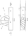
- FIG. 2A depicts impeller 200 in accordance with the illustrative embodiment of the present invention.
- Impeller 200 has hub 202 that supports blade 204.
- Embodiments of an impeller in accordance with the present teachings will usually, but not necessarily, include at least two blades. This is particularly important for impellers that are intended to rotate at speeds of thousands of rpm, such as is required for a percutaneously-inserted blood pump. Impeller 200 can be assumed to possess a second blade, which is not shown for the sake of clarity.
- Blade 204 comprises a plurality of bladelets 206- i .
- blade 204 includes five bladelets.
- fewer bladelets or more bladelets may suitably be used as a function, for example, of the chord length of blade. More particularly, a blade having a relatively longer chord length will generally have more bladelets than a blade having a relatively shorter chord length.
- Each bladelet 206- i is characterized as having root 208, tip 210, leading edge periphery 212 and trailing edge periphery 214.
- the distance between root 208 and tip 210 depicts the span of the bladelet.
- the distance between leading edge periphery 212 and trailing edge periphery 214 depicts the extent of bladelet 206- i in the chord-wise direction.
- the ratio of the chord of tip 210 to the chord of root 208 of each bladelet is typically in a range from about 1 to about 4, and more typically in a range from about 1.5 to about 3.
- the ratio of the span of a bladelet to the chord length of tip 210 of a bladelet is typically in a range from about 1 to about 4, and more typically in a range from about 2 to about 4.
- the ratio of the span of bladelet 206- i to the diameter of hub 202 is typically in a range from about 0.5 to about 3, and more typically in a range from about 1 to about 2.
- adjacent bladelets overlap near tip 210.
- the precise amount of overlap will vary as a function of bladelet geometry; in particular the ratio of the chord length of tip 210 to the chord length of root 208, among other parameters. The greater the ratio, the greater the overlap, as a function of the root spacing between adjacent bladelets.
- overlap is minimal, such that the trailing edge and leading edge at tip 210 of adjacent bladelets simply abut each other. But in all embodiments in accordance with the present teachings, there must be at least minimal contact at the tip of adjacent bladelets. This ensures that the bladelets collectively define a single blade. If space is present between adjacent bladelets, then those bladelets are part of two different blades in two different blade rows.
- bladelets 206- i are foldable.
- FIG. 2A can be considered to depict the bladelets in an unfolded or deployed state and FIG. 2B shows the bladelets in a folded or delivery state. As depicted in FIG. 2B , bladelets 206- i fold at location 216 near root 208.
- the bladelets are formed from a material that is characterized by a resilience or an ability to return to a specific configuration once a restraining force that is deforming the bladelets is withdrawn.
- the bladelets can be folded by advancing conduit 218 ( e.g., catheter, etc.) over hub 202 and the bladelets. In this folded state, the collapsed diameter of impeller 200 is not substantially larger than the diameter of hub 202.
- Bladelets When conduit 218 is withdrawn, the bladelets unfold (via the potential energy stored in the bladelets during the folding process). Bladelets having an ability to fold and unfold are particularly useful in conjunction with percutaneously-inserted blood pumps.
- An embodiment of blood pump utilizing an impeller in accordance with the present teachings is described later in this disclosure.
- Foldable bladelets can suitably be formed from superelastic Nitinol, stainless steel, or various polymers, such as polyimide, polypropylene, and the like.
- Hub 202 is suitably formed from stainless steel, nitinol, or any of a variety of polymers.
- blade 204 The geometry ( e.g., chord, etc .) of blade 204 is application specific. For most applications, blade 204 will wrap at least partially around hub 202 along a helical path. For use in an expandable blood pump, blade 204 will wrap around hub 202 over an angle that is typically in the range of about 30 to 90 degrees. But, as a function of application specifics, blade 204 can wrap a full 360 degrees or more.
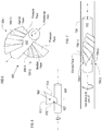
- FIG. 3 depicts impeller 300, wherein blade 304 comprising a plurality of bladelets 306- i wraps over 180 degrees about hub 302.
- blade row most impellers, and particularly those intended to operate at high rotational speeds, will typically have at least two blades that are equally circumferentially spaced-apart about the impeller hub. That is, the impeller (or blade row) will exhibit n-fold symmetry such that the blades are positioned about 360/n degrees apart from each other about the circumference of the hub, wherein n is the total number of blades in the blade row.
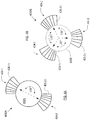
- FIGs. 4A and 4B depict two examples of impellers in accordance with the present teachings that display n -fold symmetry.
- FIG. 4A depicts an end view of impeller 400A having two blades 404-1 and 404-2, each comprising a plurality of bladelets 406-1- i and 406-2- i , respectively.
- Blades 404-1 and 404-2 are spaced 360/ n degrees apart, where n equals 2, or 180 degrees apart about hub 402A.
- FIG. 4B depicts an end view of impeller 400B having three blades 404-1, 404-2, and 404-3, each comprising a plurality of bladelets 406-1- i , 406-2- i , and 406-3- i , respectively.
- Blades 404-1, 404-2, and 404-3 are disposed 360/ n degrees apart, where n equals 3, or 120 degrees apart about hub 402B.
- FIG. 5 depicts impeller 500 in accordance with a variation of the illustrative embodiment.
- Impeller 500 includes two blades 504-1 and 504-2 that are organized into a single blade row about hub 502.
- blade 504-1 comprises a plurality of overlapping bladelets 506-1- i
- blade 504-2 comprises a plurality of overlapping bladelets 506-2- i .
- each blade comprises five bladelets.
- impeller 500 The operational rotational direction of impeller 500 is indicated by the arrow in FIG. 5 ( i.e., counterclockwise).
- the fluid to be pumped is flowing "out of the page.”
- the pressure face of each bladelet 506-1- i in blade 504-1 is the "visible” face (in FIG. 5 ).
- the suction face of bladelets 506-1- i is the obscured face.
- the pressure face of each bladelet 506-2-i in blade 504-2 is the "visible” face and the suction face is the obscured face.
- the pressure face of the bladelets is concave and the suction face of the bladelets is convex .
- the concave face of the bladelets is the leading face ( i.e., the face that is pushing through the fluid).
- this geometry is analogous to that of a metallic wind-up tape measure.
- a tape measure can be extended many feet against gravity, yet remain substantially straight if the tape is in a concave-side-up orientation. In this orientation, the concave side of the tape measure is exposed to the load (i.e., gravity). If, however, the tape measure is inverted, so that it assumes a concave-side-down orientation, the tape will readily succumb to gravity and buckle and fold. In this manner, the curvature of the tape measure provides rigidity against buckling/folding when exposed to loads, but only in one direction.
- bladelets 506-1- i and 506-2- i depicted in FIG. 5 provide the same one-way rigidity when exposed to a load, such as the mass of the fluid being pumped. But it is critical that the pressure face is concave.
- FIG. 6 depicts additional detail of an individual bladelet, which is representative of bladelets 506-1- i and 506-2- i .
- Other bladelets that would normally be present to collectively define a blade are not depicted in FIG. 6 for the sake of clarity.
- the bladelet depicted in FIG. 6 is characterized by root 608, tip 610, edge 612 and edge 614.
- Face 620 is concave and face 622 is convex.
- the ratio of the chord length of tip 610 to the chord length of root 608 of each concave/convex bladelet is typically in a range from about 1 to about 4, and more typically in a range from about 1.5 to about 3.
- the ratio of the span of a bladelet to the chord length of tip 610 of a bladelet is typically in a range from about 1 to about 4, and more typically in a range from about 1.5 to about 4.
- the ratio of the span of a bladelet to the diameter of hub 602 is typically in a range from about 0.5 to about 3, and more typically in a range from about 1 to about 2.
- the radius of curvature of root 608 is typically in a range of about 0.2 to about 2.5 times the chord length of the root. This equates to curvature for root 608 that is in a range of about 12 degrees to about 150 degrees. More typically, the curvature of root 608 will be within the range of about 30 degrees to about 60 degrees.
- adjacent bladelets 506-1- i in blade 504-1 overlap near the tips thereof.
- adjacent bladelets 506-2- i in blade 504-2 overlap near the tips thereof.
- the precise amount of overlap will vary as a function of bladelet geometry; in particular the ratio of the chord length of tip 610 ( FIG. 6 ) to the chord length of root 608, among other parameters. The greater the ratio, the greater the overlap, as a function of the root spacing between adjacent bladelets. In some embodiments, overlap is minimal, such that the trailing edge and leading edge at the tip of adjacent bladelets simply abut each other.
- the concave/convex bladelets disclosed herein are foldable, like bladelets 206- i .
- FIG. 5 can be considered to depict the bladelets of an impeller in an unfolded or deployed state and
- FIG. 7 shows bladelets of an impeller in a folded or delivery state.
- the concave/convex bladelets are formed from a material that is characterized by a resilience or an ability to return to a specific configuration once a restraining force that is deforming the bladelets is withdrawn.
- Foldable bladelets can suitably be formed from superelastic Nitinol, stainless steel, or various polymers, such as polyimide, polypropylene, and the like.
- foldable concave/convex bladelets can be folded by advancing conduit 728 (e.g ., catheter, etc.) over hub 702 and bladelets 706-1- i of blade 706-1 and 706-2- I of blade 706-2. (Most of the bladelets of blade 706-2 are obscured.)
- conduit 728 When conduit 728 is withdrawn, the bladelets unfold via the potential energy stored in the bladelets during the folding process.
- FIGs. 8A and 8B depict two embodiments of impellers with membranes.
- FIG. 8A depicts impeller 800A having membrane 830 that completely encapsulates blade 804 and all bladelets 806- i .
- the membrane can either be bonded to the root of each bladelet or to hub 802 near the root.
- FIG. 8B depicts impeller 800B wherein membrane 840 is implemented as a webbing that is disposed between opposing peripheral edges of adjacent bladelets 806- i .
- membrane 840 covers only a portion of blade 804 whereas for the embodiment depicted in FIG. 8A , membrane 830 covers the full blade.
- the membrane may be formed from polyurethane, silicone, latex rubber, other elastomeric compounds, or a biologic membrane such as bovine pericardium.
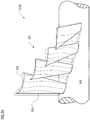
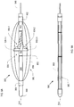
- FIGs. 9A and 9B depict the pump-assembly portion 950 of a temporary cardiac assist device or blood pump, as is suitable for percutaneous insertion into the vascular system of a patient.
- pump assembly 950 is intended for percutaneous insertion, it is advantageously sized so that it can be introduced into the vascular system (e.g ., Femoral artery, etc .) via a 12-French or smaller-diameter catheter. Historically, it has been difficult to achieve average flows greater than about 2 to 2.5 liters per minute against physiologic pressures through a 12-French catheter, which has a diameter of 4 millimeters. To that end, pump assembly 950 is collapsed for insertion and delivery, as depicted in FIG. 9B , and expanded for pumping (as depicted in FIG. 9A ) when it reaches its intended deployment site.
- vascular system e.g ., Femoral artery, etc .
- Pump assembly 950 includes proximal support housing 952, impeller 900, distal support 954, nose cone 956, casing 960, proximal support ring 962, and distal support ring 964.
- Pump assembly 950 is based on a design for a percutaneously-inserted, expandable, cardiac-assist device that was disclosed in U.S. Published Pat. Application 2008/0132747 . Pump assembly 950 departs from that design by incorporating an impeller having a plurality of overlapping bladelets as disclosed herein. That document can be referenced for additional information concerning the pump assembly design.
- Impeller 900 comprises impeller hub 902 and two impeller blades 904-1 and 904-2 that are arranged in a single blade row. Each impeller blade comprises a plurality of overlapping bladelets 906-1- i and 906-2- i .
- a plurality of spaced-apart ribs 958 are axisymmetrically arranged about central axis A-A of pump assembly 950.
- the ribs collectively define cage or casing 960.
- the ribs exhibit an arcuate shape, so that open, cage-like casing 960 adopts a typically ellipsoidal or prolate-spheroid form.
- the casing exhibits its maximum diameter. This maximum or enlarged diameter is required to accommodate impeller blades 904-1 and 904-2 when they are deployed for operation.
- Casing 960 provides one or more of the following functions:
- a membrane (not depicted for reasons of clarity) covers a portion of casing 960; the end regions of the casing remain uncovered.
- the purpose of the membrane is to channel or confine the blood in the vicinity of impeller blades 904-1 and 904-2 so that a flow field develops. Blood enters and exits pump assembly 950 through the uncovered regions of the casing.
- the membrane is formed from polyurethane, silicone, latex rubber, or other elastomeric compounds.
- ribs 958 are formed in such a way ( e.g ., processing, materials of fabrication, etc. ) that in the absence of a restraining force, they exhibit the aforementioned non-planar (e.g ., arcuate, etc. ) shape, such that pump assembly 950 "naturally" assumes the expanded configuration. As a consequence, no actuating force is required to place pump assembly 950 into its operating configuration. Rather, for such embodiments, a force must be applied to restrain pump assembly 950 from expanding.
- a super-elastic material such as nitinol, etc., can be used to form ribs 952.
- Elements of pump assembly 950 are coaxial and, in some cases, linearly arranged with respect to one another. This provides stability to pump assembly 950.
- proximal support housing 952, impeller hub 902, and distal support 954 are linearly arranged.
- Proximal support housing 952 and impeller hub 902 are coaxial with respect to drive shaft 948.
- Casing 960 which comprises ribs 958, proximal support ring 962, and distal support ring 964, is coaxial with respect to proximal support housing 952, impeller hub 902, and distal support 954.
- proximal support housing 952, impeller hub 902, and distal support 954 comprise injection molded polymer.
- the proximal end of the drive cable is coupled to the motor and the distal end of the drive cable is coupled to drive shaft 948.
- the drive shaft enters the proximal end of pump assembly 950 and is operatively coupled to impeller hub 902.
- the drive shaft extends a relatively short distance (less than about 3 centimeters) proximal of pump assembly 950.
- the drive cable and the drive shaft are distinct components and the distinction between them is an important one.
- the drive cable must be flexible to enable it to be easily advanced in the vasculature and, if required, beyond the aortic arch.
- drive shaft 948 is rigid in order that the requisite seal and bearing in proximal support housing 952 function properly.
- drive shaft 948 passes through proximal support housing 952 to impeller hub 902 and terminates therein. In some embodiments, the drive shaft terminates approximately at the axial midpoint of impeller hub 902.
- Proximal support housing 952 provides a non-rotating support surface for the proximal support ring 962, thereby supporting the proximal end of casing 960. Since casing 960 does not rotate, it cannot couple to a rotating surface, such as impeller hub 902.
- proximal support housing 952 does not rotate but impeller hub 902 does, they are separated by gap. And since drive shaft 948 passes through proximal support housing 952, a bearing must be provided within the housing to accommodate the rotational movement of drive shaft 948. A seal must also be provided within proximal support housing 952 to prevent blood from entering. If blood were to enter housing 952 in the small gap between drive shaft 948 and the bore that accepts it, the blood might be hemolyzed by the action of drive shaft 948.
- the bore of the bearing within proximal support housing 952 provides substantially all of the structural rigidity for impeller blades 904-1 and 904-2 /impeller hub 902.
- Materials suitable for the bearing include, without limitation, low friction polymers, such as Teflon® (polytetrafluoroethylene), Torlon® (polyamide-imide), Rulon® (propriety polytetrafluoroethylene-based compounds), Vespel® (thermoplastic polyimide) sleeve bearings, biocompatible bearings and the like.
- low friction polymers such as Teflon® (polytetrafluoroethylene), Torlon® (polyamide-imide), Rulon® (propriety polytetrafluoroethylene-based compounds), Vespel® (thermoplastic polyimide) sleeve bearings, biocompatible bearings and the like.
- polyurethane or silicon lip seals or o-rings are used as the seal.
- drive shaft 948 is formed as an integral part of impeller hub 902. In some other embodiments, impeller hub 902 is formed around drive shaft 948. In any case, drive shaft 948 is rigidly coupled to impeller hub 902 to efficiently drive the impeller blades.
- Drive shaft 948 is formed of stainless steel or other materials having specific dimensions, hardness, surface finish, and radiused edges for damage-free seal insertion. Surface finish will be specified by the bearing or seal manufacturer to ensure compatibility with same.
- the drive cable (not shown) is formed of stainless steel (but in such a way that the cable remains flexible). In some embodiments, the drive cables disclosed in U.S. Pat. Application S.N. 11/758,402 are used.
- Impeller blades 904-1 and 904-2 are depicted in a deployed or unfolded state in FIG. 9A . In this state, they extend substantially orthogonally from impeller hub 902.
- the impeller blades comprise a plurality of bladelets, consistent with embodiments described earlier in this disclosure.
- the bladelets have concave pressure side and a convex suction side, as per impeller 500 of FIG. 5 .
- the bladelets of impeller blades 904-1 and 904-2 are biased to deploy; that is, they must be restrained to be kept in the folded state.
- the bladelets are formed of a resilient material, as previously described.
- the bladelets must be "spun-up" to the deployed state. In other words, the rotation of the impeller hub causes the bladelets to deploy.
- impeller 900 In a collapsed state, impeller 900 has a diameter of about 3 millimeters (9 Fr).
- the design speed of the impeller is in the range of between about 1,000 RPM to about 20,000 RPM.
- the impeller is expected to pump at least 2.5 liters per minute of blood at 100 mmHg (4 cP) and 37°C using a 10 Fr delivery system.
- the impeller is designed for a 100% duty cycle for a seven-day service life.
- Casing 960 is advantageously supported at its distal end. Such support is provided by distal support 954, which receives distal support ring 964. Like proximal support housing 952, the distal support is not rotating. Since, however, impeller hub 902 is rotating, the impeller hub and distal support 954 are separated by a gap. Because drive shaft 948 does not extend beyond the impeller blades, a locating pin or other means is required to couple distal support 954 to impeller hub 902.
- locating pin 953 depends from proximal end of distal support 954.
- the pin couples the proximal end of the distal support to the distal end of impeller hub 902.
- Disposed within the distal end of impeller hub 902 are a bearing and seal (not depicted). Since, as previously disclosed, impeller hub 902 is rotating and distal support 954 is not, a bearing is required to accommodate the differential movement. And the seal prevents leakage of blood into impeller hub 902.
- the bearing and seal in the impeller hub are formed of the same materials as the bearing and seal in proximal support housing 952.
- distal support 954 terminates in nose cone 956, which provides an atraumatic surface that is contoured for easy insertion and navigation through a patient's vascular system.
- FIG. 9B depicts pump assembly 950 in its delivery state.
- casing 960 (and pump assembly 950) exhibits its minimum diameter.
- ribs 952 are straight and substantially parallel to axis A-A of pump assembly 950.
- Casing 960 adopts a substantially cylindrical shape.
- pump assembly 950 has a relatively smaller diameter, the task of negotiating the vascular system, and in particular the aortic arch, is simplified. As a consequence, pump assembly 950 is introduced into the body ( e.g. , the femoral artery, etc. ) in the folded or delivery state. Typically, it is after pump assembly 950 has passed the aortic arch and entered the ascending aorta or other final locations that casing 960 is expanded for operation.
- body e.g. , the femoral artery, etc.
- pump assembly 950 is deployed into the vascular system via an "introducing" tube, such as a catheter, sheath, or the like.
- the wall of the introducing tube provides the restraining force to maintain casing 960 in the contracted state.
- pump assembly 950 is simply advanced beyond the distal end of the tube.
- the introducing tube must possess a suitably radially-inelastic wall. Standard catheters are suitably radially-inelastic for this purpose. In conjunction with the present disclosure, it is within the capabilities of those skilled in the art to provide an introducing tube having a suitably radially-inelastic wall to maintain casing 960 in the contracted state.
- One of either the proximal end or the distal end of casing 960 is movable in an axial direction. This facilitates the expansion and contraction of the casing.
- casing 960 is to be collapsed simply by the act of inserting the proximal end of pump assembly 950 into an introduction/extraction catheter, then it is advantageous (but not necessary) for the distal end of casing 960 to be the movable end.
- distal support ring 964 is movably coupled to distal support 964 so that it is able to readily slide along the support in either direction.
- Pump assembly 950 may be collapsed as follows for extraction from the vascular system.
- impeller 900 is rotated slowly in the reverse direction, such that the convex face of the bladelets becomes the pressure face.
- the bladelets will readily collapse once the convex side is exposed to a load. Pump assembly is then drawn back into the introducing tube.
- the bladelets might or might not remain collapsed (after the cessation of reverse impeller rotation).
- the pump assembly is drawn back into the introducing tube while the impeller is still in motion.
- the reverse rotational motion is stopped only after the pump assembly is within the introducing tube, wherein the wall of the tube will maintain the bladelets in the collapsed state.
- impeller rotation is simply stopped and pump assembly 950 is drawn back into the introducing tube.
- One benefit of the curved structure of the bladelets is that, even though the "closure" force is being applied to the side that is best able to resist it, once the buckling force is exceeded, the bladelets will readily fold and collapse against hub 902.
Landscapes
- Engineering & Computer Science (AREA)
- Health & Medical Sciences (AREA)
- Heart & Thoracic Surgery (AREA)
- Mechanical Engineering (AREA)
- Hematology (AREA)
- Cardiology (AREA)
- Anesthesiology (AREA)
- Biomedical Technology (AREA)
- General Engineering & Computer Science (AREA)
- Life Sciences & Earth Sciences (AREA)
- Animal Behavior & Ethology (AREA)
- General Health & Medical Sciences (AREA)
- Public Health (AREA)
- Veterinary Medicine (AREA)
- Vascular Medicine (AREA)
- External Artificial Organs (AREA)
- Structures Of Non-Positive Displacement Pumps (AREA)
Description
- An impeller is a rotating component that includes a hub and at least one blade. In operation, the impeller is used to accelerate and/or pressurize a fluid. More particularly, an impeller converts the rotary mechanical energy of a drive (e.g., a motor, etc.) into kinetic energy (flow) and potential energy (pressure) of a fluid being acted upon. Impellers are used in various types of equipment, including pumps, water jets, agitated tanks, washing machines, and vacuum cleaners, to name but a few.
- The impeller is designed to enable a pump, etc., to achieve certain performance characteristics, such as a certain mass flow rate, pressure ratio, and/or efficiency. Device performance is ultimately a function of the operating conditions (e.g., inlet pressure, temperature, fluid density, etc.) as well as geometrical parameters of the impeller (e.g., hub diameter, blade geometry, etc.).
- Impeller blades often have a very complex blade geometry intended to optimize hydrodynamic efficiency or meet other design criteria. Furthermore, the structure of impeller blades can vary dramatically as a function of intended application. Consider, for example, an airplane propeller blade or mixer blade. These blades tend to be relatively long in span and short in chord length. Contrast those blades with a screw-type impeller blade (e.g., Archimedes screw, etc.) having a single helical vane that exhibits a significant degree of wrap around the central hub. These screw-type blades are relatively short in span and long in chord length.
- U.S. Patent Application Publication
US 2006/0062672 A1 shows an expandable impeller pump comprising a hub, and at least one blade supported by the hub. The impeller has a deployed configuration in which the blade extends away from the hub. The impeller may comprise a plurality of blades, arranged in blade rows, to facilitate radial compression of the blades. - There are some specialized applications in which the impellers might have additional design requirements, such as an ability to expand and collapse. One such application is the percutaneously-inserted blood pump.
- A blood pump is a cardiac-assist device that is useful as an intervention for some patients who have acute heart failure or who are at risk of developing it. An effective cardiac assist device assumes some of the heart's pumping function, thereby unloading the heart and enabling it to recover. The blood pump is typically intended as a temporary measure, usually in operation for less than a week.
- Percutaneously-inserted blood pumps are designed to be inserted into a patient using a minimally-invasive procedure. These blood pumps are usually inserted via established cath-lab techniques, such as by inserting the blood pump into a peripheral vessel (e.g., femoral artery, etc.) and advancing it to the ascending aorta or the heart (e.g., Seldinger, etc.). To be percutaneously inserted into a peripheral vessel, a blood pump must be quite small. In particular, it is desirable for these blood pumps to have a 12-French (4 millimeter) or smaller catheter. This places a severe constraint on the size of the impeller blades and, hence, the amount of blood that the device can pump.
- In an attempt to address this size constraint, the "expandable" blood pump has been proposed. This type of pump, which is suitably small for percutaneous insertion, includes an impeller that expands once in place within the heart or larger vasculature nearby. The blade span attained by the expanded impeller is greater than is otherwise possible for a non-expandable impeller (that is also percutaneously inserted). As a consequence, the expandable impeller can pump more blood per revolution and operate at a lower rotational speed. Most expandable blood pumps use one of several different implementations of the expandable impeller: inflatable impellers, pivoting impellers, or foldable impellers. Some examples of prior-art blood pumps that use these types of impellers are discussed below.
-
U.S. Pat. No. 6,981,942 discloses a percutaneously-insertable blood pump having an inflatable housing and an inflatable impeller, which includes an inflatable hub and a single blade-row of inflatable blades. The housing is attached to a long sheath that couples the pump (ultimately sited in/near the heart) to extracorporeal elements, such as a motor and source of pressurized air. A drive shaft that couples the impeller to the motor and inflation tubes for inflating the housing and impeller are disposed in the sheath. -
U.S. Pat. No. 5,749,855 discloses a percutaneously-insertable blood pump having a pivoting impeller. The impeller comprises a single blade row of two blades that are surrounded by an expandable cage. A drive cable extends from an extracorporeal motor to the distal end of the cage. In the absence of an applied, axially-directed force, the cage and impeller remain in a collapsed state. - The drive cable is designed so that its inner part is movable relative to its outer part. As the inner part of the drive cable is drawn in the proximal direction by an axially-applied force (e.g., by a medical practitioner tugging on the inner part), relative movement between the inner and outer parts of the drive cable expands the cage and pivots the blades into a deployed state. The deployed propeller can then freely spin within the expanded cage.
-
U.S. Pat. No. 6,533,716 discloses a percutaneously-insertable blood pump having a foldable helical rotor. The rotor consists of a helical frame, which is embodied as a helically-twisted segment of Nitinol wire. Both ends of the helically-twisted segment are coupled to an elastic band that lies along the axis of rotation of the helical frame. A surface of the rotor "blade" is formed from a membrane that extends between the helical frame and the centrally-disposed elastic band. The membrane is formed from a spongy, woven tissue. - The helical rotor is in a collapsed state for insertion into the vascular system. In this state, a tube overlies the helical frame and forces it into an elongated configuration along the central axis. The centrally-disposed elastic band is under maximum tension and the covering membrane is compressed. When the covering tube is withdrawn, the elongated Nitinol wire contracts axially and assumes the helical shape. As this occurs, the elastic band contracts and the membrane forms a smooth surface that functions as the surface of the rotor.
-
U.S. Pat. No. 4,753,221 discloses a percutaneously-insertable blood pump that includes attributes of both inflatable and foldable impellers. This blood pump comprises a catheter, the distal end of which is formed from a flexible material that is capable of expanding. Blades, which are disposed in a single blade row, are formed from an elastic material and are disposed in the catheter at the flexible region. When the catheter is in a delivery or collapsed state, the blades are "bent over," substantially parallel to the rotational axis of the pump. To deploy the blades, the distal end of the catheter is enlarged by inflating a balloon that couples to the exterior of the catheter. As the distal end of the catheter expands, the blades unfold into an operational position wherein they extend orthogonally to the rotational axis. -
U.S. Pat. No. 4,919,647 discloses a percutaneously-insertable blood pump having a catheter to which four foldable impeller blades arranged in a single blade row are coupled. The blades are formed of an elastic material and are biased to naturally project radially outward. The blades are disposed in the distal end of a catheter, which has a cup-shaped form and is made from an expandable material. For insertion into a patient, the impeller blades and the cup-shaped portion are contracted radially inward, such as by placing the catheter within a tubular guide. When the guide is removed, the blades and the cup-shaped portion expand. -
U.S. Publ. Pat. Appl. No. 2008/0114339 discloses a percutaneously-insertable blood pump having an impeller with foldable blades arranged in a plurality of blade rows. This reference discloses that it is difficult to fold a long helical blade that exhibits a substantial amount of wrap around the central hub. To address this problem, the reference discloses that a long blade should be segregated into two, three or perhaps more shorter blades that are arranged (i.e., spaced apart) into a like number of blade rows. - Although impeller design is a well-understood discipline, the expandable impeller, especially in the context of a blood pump, raises a variety of design challenges. In particular, and among any other issues, careful consideration must be paid to the structural adaption of the impeller that enables it to expand/collapse and the manner in which expansion/collapse is actuated. These issues are important because they typically affect the structural configuration of the surrounding pump structure (e.g., pump housing, etc.) and the way in which the impeller is integrated in the surrounding structure.
- It is notable that even though the patent literature is replete with expandable blood pumps, including those discussed above, not one of them is currently in use. A need therefore remains for an expandable impeller that can be used in percutaneously-insertable blood pumps, among other applications.
- The present invention provides an impeller useful in pumps and other rotating equipment. In the illustrative embodiment, the impeller is used in conjunction with a percutaneously-inserted, expandable, cardiac-assist device.
- In approaching the problem of developing an impeller suitable for use in a percutanteously-insertable blood pump, the present inventor recognized that it would be desirable for the impeller to operate at relatively lower speeds (e.g., less than about 5,000 rpm). Operating at relatively lower speeds will extend the life of a drive cable that couples an extracorporeal motor to the pump. To pump the typically-desired amount of blood (i.e., about 2.5 liters per minute or more) when operating at such lower speeds requires an impeller having a blade span that is too large to introduce through the human vasculature via a percutaneous technique. As a consequence, the present inventor reached the conclusion that a collapsible/expandable impeller design was indicated.
- Typically, impeller design and blade geometry is dictated almost exclusively by hydrodynamic considerations. That is why impeller blades usually have an airfoil or other highly complex shape. Once a particular geometry is developed, materials of construction and blade thickness are selected to provide the requisite strength, etc. And that is one reason why such blades are usually relatively thicker near the root and thinner near the tip.
- The present inventor, however, approached the task of impeller design from a different perspective. In particular, the impetus for the impeller design and blade geometry was based primarily on considerations of structural rigidity and strength. That is, since the impeller blades, at least in some embodiments, are intended to be foldable, they must be able to resist inadvertent buckling or folding during operation.
- Impeller blades typically have a pair of opposed faces: a pressure face that induces relative motion of the fluid as the blade rotates and a suction face that induces motion of the fluid via suction. The pressure and suction faces are usually curved in the same general direction, defining an airfoil shape. Some embodiments of impellers disclosed herein do not exhibit this airfoil geometry.
- Analogizing to a metallic wind-up tape measure, the present inventor recognized that a blade having a pressure face that was concave and a suction face that was convex would provide excellent resistance to folding when the force was applied to the concave face. So, in accordance with the present invention, the structural rigidity of the impeller blades is imparted through blade geometry whereas in the prior art, it is primarily imparted through materials selection.
- Consider the metallic tape measure. It can be extended horizontally many feet against gravity, yet remain substantially straight, if the tape is in a concave-side-up orientation. If, however, the tape measure is inverted, so that it assumes a concave-side-down orientation, the tape will readily succumb to gravity by folding. The tape measure therefore buckles readily if force is applied to the convex side, but is far more effective at resisting buckling if the force is applied to the concave side. In other words, the curvature of the tape measure provides rigidity against buckling/folding when exposed to loads, but only in one direction.
- This configurationally-imparted rigidity is very advantageous for an expandable impeller. Given a required rigidity and a particular material of construction, an impeller having the concave/convex geometry described herein can be formed from less material than would otherwise be possible with conventional designs. Less torque is therefore required to drive the impeller to given speed. This places less stress on the drive cable, which has historically been a point of weakness for percutaneously-insertable blood pumps.
- Furthermore, the property of one-way rigidity can be very advantageous for an expandable impeller. In particular, in applications that permit, the impeller can be collapsed for extraction by simply reversing the direction of rotation of the impeller.
- The use of a concave profile for the pressure face of an impeller blade was the first of several important insights. To gain the benefit of this geometry, the present inventor recognized that it would be important to have a relatively small radius of curvature (i.e., a relatively sharp curve) at the root of the blade to resist folding. If the radius of curvature were to flatten towards infinite curvature (i.e., a straight line) at the root, the ability to resist folding would decrease. Yet, from the perspective of pumping fluid, a much greater radius of curvature (i.e., flatter curve) is desirable near the tip of the blade, since this provides better flow tangency (to the blade), which provides for more efficient pumping.
- The aforementioned criteria dictate a blade that is very narrow in chord length near the root but quite wide in chord length at the tip. Notwithstanding the sharply curved root and its potential benefit for rigidity, it is likely that the moment created at the blade tip during operation would collapse a blade having such an extreme tip-to-root aspect ratio.
- The present inventor recognized that these countervailing requirements could be reconciled by segmenting the blade into a plurality of discrete "bladelets." Neighboring bladelets are spaced apart at the root but, as a minimum, abut each other at the tip. Preferably, neighboring bladelets will actually overlap each other beginning at some radial distance short of the tip. Segmenting a blade in this manner permits a small radius of curvature at the root of a bladelet and a substantially greater radius of curvature at the tip without resulting in an extreme tip-to-root aspect ratio as with a "full" non-segmented blade. Yet, a "blending" of adjacent bladelets occurs to provide a substantially continuous helical blade, particularly at greater radial distances from the hub where most of the pumping work is accomplished. This maintains the efficiency of the impellers disclosed herein.
- Rigidity notwithstanding, impellers described herein must be appropriately efficient and any design thereof must be vetted using computational fluid dynamics, as is known to those skilled in the art.
- For example, in some embodiments, there will be open space between adjacent bladelets beneath the tips thereof. Fluid (e.g., blood, etc.) will pass through this space, thereby resulting in decreased impeller efficiency. To prevent that from happening, in some embodiments, a membrane is disposed over or between the bladelets.
- In some embodiments, an impeller for use in conjunction with a percutaneously-insertable blood pump will therefore advantageously include a blade that is segmented into a plurality of overlapping or abutting bladelets, wherein the bladelets are foldable, wherein one side of each bladelet is concave and the other side is convex, and wherein the root of each bladelet is smaller in chord length and has a smaller radius of curvature than the tip thereof. Furthermore, the bladelets are covered by a membrane. The impellers described herein are axial-flow impellers. In some other embodiments, impellers in accordance with the present teachings are implemented as mixed-flow impellers (both axial and radial flow).
- Impellers possessing some but not all of the features described above will have utility and provide benefits in a variety of applications. Therefore, in some other embodiments, such as may be used for a percutaneously-insertable blood pump or other rotating equipment, an impeller in accordance with the present teachings will include one or more, but not necessarily all, of the following features:
- one or more blades that are segmented into a plurality of overlapping/abutting bladelets; and/or
- a membrane covers the blade(s); and/or
- bladelets in which the pressure face is concave; and/or
- bladelets in which the suction face is convex; and/or
- foldable bladelets; and/or
- the chord length of the root of a bladelet is smaller than the chord length of the tip of the bladelet; and/or
- the radius of curvature of the root of a bladelet is smaller than the radius of curvature of the tip of the bladelet.
- One or more blades that are segmented into a plurality of overlapping/abutting bladelets that are not foldable and do not have a pressure face that is concave.

- One or more blades that are segmented into a plurality of overlapping/abutting bladelets that are foldable and do not have a pressure face that is concave.
- One or more blades that are segmented into a plurality of overlapping/abutting bladelets that are not foldable and do have a pressure face that is concave.
- A single blade that is segmented into a plurality of overlapping/abutting bladelets that is foldable and has a pressure face that is concave.
- In accordance with the illustrative embodiment, a percutaneously-inserted cardiac-assist device includes a pump assembly that includes an impeller as described herein. The pump assembly is deployed in the aorta, heart, or other major vessels. A drive cable couples the pump assembly to an extracorporeal motor. The motor, via the drive cable, drives the impeller.
-
-
FIG. 1A depicts a representation of a prior-art impeller having a single blade row. -
FIG. 1B depicts a representation of a prior-art impeller having two blade rows. -
FIG. 2A depicts an embodiment of an impeller comprising bladelets in accordance with the illustrative embodiment of the present invention. The impeller is shown in a deployed or unfolded state and depicts overlap between adjacent bladelets. -
FIG. 2B depicts the impeller ofFIG. 2A , but in a folded or delivery state. -
FIG. 3 depicts an embodiment of an impeller comprising abutting bladelets in accordance with the present teachings. The impeller depicts a helical blade that exhibits more than 180 degrees of wrap around the hub. -
FIG. 4A depicts an end view of an impeller in accordance with the present teachings, wherein the impeller has one blade row with two blades and exhibits bilateral symmetry. -
FIG. 4B depicts an end view of an impeller in accordance with the present teachings, wherein the impeller has one blade row with three blades and exhibits tri-lateral symmetry. -
FIG. 5 depicts an embodiment of an impeller comprising bladelets in accordance with the illustrative embodiment of the present invention. The bladelets exhibit a "tape-measure" geometry, wherein one side of each bladelet is concave and the other is convex. -
FIG. 6 depicts further detail of a bladelet exhibiting tape-measure geometry in accordance with present teachings. -
FIG. 7 depicts an embodiment of an impeller similar toFIG. 5 and wherein the bladelets of the blade are in a folded or delivery state. -
FIG. 8A depicts an embodiment of an impeller in accordance with the present teachings, wherein a blade, which comprises a plurality of bladelets, is covered by a membrane. -
FIG. 8B depicts an embodiment of an impeller in accordance with the present teachings, wherein a membrane connects adjacent bladelets of an impeller blade. -
FIG. 9A depicts a blood pump that incorporates an expandable impeller in accordance with the present teachings. The blood pump is shown in an operational state in which the impeller is deployed or unfolded. -
FIG. 9B depicts the blood pump ofFIG. 9A , wherein the blood pump is shown in a collapsed or delivery state in which the impeller is folded. - The following explicit definitions are provided for various terms that appear in this disclosure and the appended claims and are to be used for the interpretation thereof.
- "Bladelet" means a discrete segment of an impeller blade; that is, a plurality of bladelets compose a single impeller blade. Tips of adjacent bladelets abut one another or overlap. (Non-traditional definition.)
- "Blade row" is a grouping of impeller blades that have a similar axial position along a hub and are typically equally circumferentially spaced apart. By way of example,
FIGs. 1A and 1B depict conventional impellers with blades arranged in blade rows. -
FIG. 1A depictsimpeller 100A, which has fourblades 104 that are grouped into asingle blade row 106 onhub 102.Blades 104 are relatively long in span and short in chord, like those of an airplane propeller.FIG. 1B depictsimpeller 100B having hub 112 that supports twoblades rows blade row 120. Similarly, blades 118-1 and 118-2 are arranged inblade row 124. The blades inblade rows hub 112. - The blades within a given blade row can exhibit a slight axial offset with respect to each other. For example, in
blade row 120 ofimpeller 100B, leading edge 126-1 of blade 114-1 is forward of leading edge 126-2 of blade 114-2. - "Chord" or ("chord length") is a straight line (or the length thereof) connecting the leading and trailing edges of a blade or bladelet.
- "Helix" or "helical" means the curve formed by a straight (or curved) line drawn on a plane when that plane is wrapped around a cylindrical (or conical) surface of any kind, especially a right circular cylinder, as the curve of a (variable-pitch) screw.
- "Multi-stage Pump" means a pump having an impeller having blade rows of rotating blades that are interspersed between blade rows of stator (non-rotating) blades that are attached to a housing. As a result, the flow path proceeds from rotor to stator (i.e., from one stage to the next) changing direction and using its momentum from the multiple changes in velocity and direction to achieve higher pressure head.
- "Pressure face" means, in the context of an impeller blade or bladelet, the pump-discharge-side face.
- "Root" means, in the context of an impeller blade or bladelet, the portion thereof nearest to the hub.
- "Suction face" means, in the context of an impeller blade or bladelet, the pump-inlet-side face.
- "Tip" means, in the context of an impeller blade or bladelet, the portion furthest from the hub.
- Definitions of other terms may appear elsewhere in this disclosure.
-
FIG. 2A depictsimpeller 200 in accordance with the illustrative embodiment of the present invention.Impeller 200 hashub 202 that supportsblade 204. Embodiments of an impeller in accordance with the present teachings will usually, but not necessarily, include at least two blades. This is particularly important for impellers that are intended to rotate at speeds of thousands of rpm, such as is required for a percutaneously-inserted blood pump.Impeller 200 can be assumed to possess a second blade, which is not shown for the sake of clarity. -
Blade 204 comprises a plurality of bladelets 206-i. In this embodiment,blade 204 includes five bladelets. In other embodiments, however, fewer bladelets or more bladelets may suitably be used as a function, for example, of the chord length of blade. More particularly, a blade having a relatively longer chord length will generally have more bladelets than a blade having a relatively shorter chord length. - Each bladelet 206-i is characterized as having
root 208,tip 210, leadingedge periphery 212 and trailingedge periphery 214. The distance betweenroot 208 andtip 210 depicts the span of the bladelet. The distance between leadingedge periphery 212 and trailingedge periphery 214 depicts the extent of bladelet 206-i in the chord-wise direction. - The ratio of the chord of
tip 210 to the chord ofroot 208 of each bladelet is typically in a range from about 1 to about 4, and more typically in a range from about 1.5 to about 3. The ratio of the span of a bladelet to the chord length oftip 210 of a bladelet is typically in a range from about 1 to about 4, and more typically in a range from about 2 to about 4. The ratio of the span of bladelet 206-i to the diameter ofhub 202 is typically in a range from about 0.5 to about 3, and more typically in a range from about 1 to about 2. - In the embodiment depicted in
FIG. 2A , adjacent bladelets overlap neartip 210. The precise amount of overlap will vary as a function of bladelet geometry; in particular the ratio of the chord length oftip 210 to the chord length ofroot 208, among other parameters. The greater the ratio, the greater the overlap, as a function of the root spacing between adjacent bladelets. - In some embodiments, overlap is minimal, such that the trailing edge and leading edge at
tip 210 of adjacent bladelets simply abut each other. But in all embodiments in accordance with the present teachings, there must be at least minimal contact at the tip of adjacent bladelets. This ensures that the bladelets collectively define a single blade. If space is present between adjacent bladelets, then those bladelets are part of two different blades in two different blade rows. - In some embodiments, bladelets 206-i are foldable. In such embodiments,
FIG. 2A can be considered to depict the bladelets in an unfolded or deployed state andFIG. 2B shows the bladelets in a folded or delivery state. As depicted inFIG. 2B , bladelets 206-i fold atlocation 216 nearroot 208. - It is to be understood that, for drawing convenience, Figures that show an impeller in two different states (i.e., unfolded and folded), such as
FIGs. 2A/2B (see alsoFIGs. 5 and 7 ), do not necessarily depict the same impeller. That is, for pedagogical purposes or other reasons, an impeller might appear as a "right-handed" screw in one Figure and as a "left-handed" screw in what appears to be a complementary Figure. This apparent "inconsistency" is inconsequential since it is not germane to the purpose of the illustrations and will not cause any confusion for those skilled in the art. - In some embodiments, the bladelets are formed from a material that is characterized by a resilience or an ability to return to a specific configuration once a restraining force that is deforming the bladelets is withdrawn. For example, the bladelets can be folded by advancing conduit 218 (e.g., catheter, etc.) over
hub 202 and the bladelets. In this folded state, the collapsed diameter ofimpeller 200 is not substantially larger than the diameter ofhub 202. - When
conduit 218 is withdrawn, the bladelets unfold (via the potential energy stored in the bladelets during the folding process). Bladelets having an ability to fold and unfold are particularly useful in conjunction with percutaneously-inserted blood pumps. An embodiment of blood pump utilizing an impeller in accordance with the present teachings is described later in this disclosure. - Foldable bladelets can suitably be formed from superelastic Nitinol, stainless steel, or various polymers, such as polyimide, polypropylene, and the like.
Hub 202 is suitably formed from stainless steel, nitinol, or any of a variety of polymers. - The geometry (e.g., chord, etc.) of
blade 204 is application specific. For most applications,blade 204 will wrap at least partially aroundhub 202 along a helical path. For use in an expandable blood pump,blade 204 will wrap aroundhub 202 over an angle that is typically in the range of about 30 to 90 degrees. But, as a function of application specifics,blade 204 can wrap a full 360 degrees or more.FIG. 3 depictsimpeller 300, whereinblade 304 comprising a plurality of bladelets 306-i wraps over 180 degrees abouthub 302. - As noted in the definition of "blade row," most impellers, and particularly those intended to operate at high rotational speeds, will typically have at least two blades that are equally circumferentially spaced-apart about the impeller hub. That is, the impeller (or blade row) will exhibit n-fold symmetry such that the blades are positioned about 360/n degrees apart from each other about the circumference of the hub, wherein n is the total number of blades in the blade row.
-
FIGs. 4A and 4B depict two examples of impellers in accordance with the present teachings that display n-fold symmetry.FIG. 4A depicts an end view ofimpeller 400A having two blades 404-1 and 404-2, each comprising a plurality of bladelets 406-1-i and 406-2-i, respectively. Blades 404-1 and 404-2 are spaced 360/n degrees apart, where n equals 2, or 180 degrees apart abouthub 402A.FIG. 4B depicts an end view ofimpeller 400B having three blades 404-1, 404-2, and 404-3, each comprising a plurality of bladelets 406-1-i, 406-2-i, and 406-3-i, respectively. Blades 404-1, 404-2, and 404-3 are disposed 360/n degrees apart, where n equals 3, or 120 degrees apart abouthub 402B. -
FIG. 5 depictsimpeller 500 in accordance with a variation of the illustrative embodiment.Impeller 500 includes two blades 504-1 and 504-2 that are organized into a single blade row abouthub 502. In accordance with the present teachings, blade 504-1 comprises a plurality of overlapping bladelets 506-1-i and blade 504-2 comprises a plurality of overlapping bladelets 506-2-i. In this embodiment, each blade comprises five bladelets. - The operational rotational direction of
impeller 500 is indicated by the arrow inFIG. 5 (i.e., counterclockwise). The fluid to be pumped is flowing "out of the page." As a consequence, the pressure face of each bladelet 506-1-i in blade 504-1 is the "visible" face (inFIG. 5 ). The suction face of bladelets 506-1-i is the obscured face. Likewise, the pressure face of each bladelet 506-2-i in blade 504-2 is the "visible" face and the suction face is the obscured face. - In accordance with the illustrative embodiment, the pressure face of the bladelets is concave and the suction face of the bladelets is convex. In other words, during normal operation, the concave face of the bladelets is the leading face (i.e., the face that is pushing through the fluid).
- As previously described, this geometry is analogous to that of a metallic wind-up tape measure. A tape measure can be extended many feet against gravity, yet remain substantially straight if the tape is in a concave-side-up orientation. In this orientation, the concave side of the tape measure is exposed to the load (i.e., gravity). If, however, the tape measure is inverted, so that it assumes a concave-side-down orientation, the tape will readily succumb to gravity and buckle and fold. In this manner, the curvature of the tape measure provides rigidity against buckling/folding when exposed to loads, but only in one direction. Similarly, bladelets 506-1-i and 506-2-i depicted in
FIG. 5 provide the same one-way rigidity when exposed to a load, such as the mass of the fluid being pumped. But it is critical that the pressure face is concave. -
FIG. 6 depicts additional detail of an individual bladelet, which is representative of bladelets 506-1-i and 506-2-i. Other bladelets that would normally be present to collectively define a blade are not depicted inFIG. 6 for the sake of clarity. The bladelet depicted inFIG. 6 is characterized byroot 608,tip 610,edge 612 andedge 614. Face 620 is concave andface 622 is convex. - Like bladelets 206-i of
impeller 200, the ratio of the chord length oftip 610 to the chord length ofroot 608 of each concave/convex bladelet is typically in a range from about 1 to about 4, and more typically in a range from about 1.5 to about 3. The ratio of the span of a bladelet to the chord length oftip 610 of a bladelet is typically in a range from about 1 to about 4, and more typically in a range from about 1.5 to about 4. The ratio of the span of a bladelet to the diameter of hub 602 is typically in a range from about 0.5 to about 3, and more typically in a range from about 1 to about 2. The radius of curvature ofroot 608 is typically in a range of about 0.2 to about 2.5 times the chord length of the root. This equates to curvature forroot 608 that is in a range of about 12 degrees to about 150 degrees. More typically, the curvature ofroot 608 will be within the range of about 30 degrees to about 60 degrees. - Returning to
FIG. 5 , adjacent bladelets 506-1-i in blade 504-1 overlap near the tips thereof. Likewise, adjacent bladelets 506-2-i in blade 504-2 overlap near the tips thereof. The precise amount of overlap will vary as a function of bladelet geometry; in particular the ratio of the chord length of tip 610 (FIG. 6 ) to the chord length ofroot 608, among other parameters. The greater the ratio, the greater the overlap, as a function of the root spacing between adjacent bladelets. In some embodiments, overlap is minimal, such that the trailing edge and leading edge at the tip of adjacent bladelets simply abut each other. - In some embodiments, the concave/convex bladelets disclosed herein are foldable, like bladelets 206-i. In such embodiments,
FIG. 5 can be considered to depict the bladelets of an impeller in an unfolded or deployed state andFIG. 7 shows bladelets of an impeller in a folded or delivery state. - In some of the embodiments in which the concave/convex bladelets are intended to be foldable, they are formed from a material that is characterized by a resilience or an ability to return to a specific configuration once a restraining force that is deforming the bladelets is withdrawn. Foldable bladelets can suitably be formed from superelastic Nitinol, stainless steel, or various polymers, such as polyimide, polypropylene, and the like.
- For initial deployment (e.g., into a patient's vasculature, etc.), foldable concave/convex bladelets can be folded by advancing conduit 728 (e.g., catheter, etc.) over
hub 702 and bladelets 706-1-i of blade 706-1 and 706-2-I of blade 706-2. (Most of the bladelets of blade 706-2 are obscured.) Whenconduit 728 is withdrawn, the bladelets unfold via the potential energy stored in the bladelets during the folding process. - In the various embodiments of impellers disclosed herein, there is some open space between adjacent bladelets beneath the tips thereof. Fluid (e.g., blood, etc.) will pass through this space, thereby resulting in decreased impeller efficiency. To prevent that from happening, in some embodiments, a membrane is disposed over or between the bladelets.
FIGs. 8A and8B depict two embodiments of impellers with membranes. -
FIG. 8A depictsimpeller 800A having membrane 830 that completely encapsulatesblade 804 and all bladelets 806-i. The membrane can either be bonded to the root of each bladelet or tohub 802 near the root.FIG. 8B depictsimpeller 800B whereinmembrane 840 is implemented as a webbing that is disposed between opposing peripheral edges of adjacent bladelets 806-i. In other words, in the embodiment depicted inFIG. 8B ,membrane 840 covers only a portion ofblade 804 whereas for the embodiment depicted inFIG. 8A ,membrane 830 covers the full blade. - As a function of application specifics, the membrane may be formed from polyurethane, silicone, latex rubber, other elastomeric compounds, or a biologic membrane such as bovine pericardium.
-
FIGs. 9A and 9B depict the pump-assembly portion 950 of a temporary cardiac assist device or blood pump, as is suitable for percutaneous insertion into the vascular system of a patient. - Since
pump assembly 950 is intended for percutaneous insertion, it is advantageously sized so that it can be introduced into the vascular system (e.g., Femoral artery, etc.) via a 12-French or smaller-diameter catheter. Historically, it has been difficult to achieve average flows greater than about 2 to 2.5 liters per minute against physiologic pressures through a 12-French catheter, which has a diameter of 4 millimeters. To that end,pump assembly 950 is collapsed for insertion and delivery, as depicted inFIG. 9B , and expanded for pumping (as depicted inFIG. 9A ) when it reaches its intended deployment site. -
Pump assembly 950 includesproximal support housing 952,impeller 900,distal support 954,nose cone 956, casing 960,proximal support ring 962, anddistal support ring 964. -
Pump assembly 950 is based on a design for a percutaneously-inserted, expandable, cardiac-assist device that was disclosed inU.S. Published Pat. Application 2008/0132747 .Pump assembly 950 departs from that design by incorporating an impeller having a plurality of overlapping bladelets as disclosed herein. That document can be referenced for additional information concerning the pump assembly design. -
Impeller 900 comprisesimpeller hub 902 and two impeller blades 904-1 and 904-2 that are arranged in a single blade row. Each impeller blade comprises a plurality of overlapping bladelets 906-1-i and 906-2-i. - A plurality of spaced-
apart ribs 958 are axisymmetrically arranged about central axis A-A ofpump assembly 950. The ribs collectively define cage orcasing 960. In the embodiment that is depicted inFIG. 9A , wherein the pump assembly is in the expanded state, the ribs exhibit an arcuate shape, so that open, cage-like casing 960 adopts a typically ellipsoidal or prolate-spheroid form. In this state, the casing exhibits its maximum diameter. This maximum or enlarged diameter is required to accommodate impeller blades 904-1 and 904-2 when they are deployed for operation. - Casing 960 provides one or more of the following functions:
- it prevents the spinning impeller blades of
pump assembly 950 from contacting anatomical features; - it establishes structural integrity;
- it provides a framework for an overlying membrane.
- Regarding the final point above, a membrane (not depicted for reasons of clarity) covers a portion of
casing 960; the end regions of the casing remain uncovered. The purpose of the membrane is to channel or confine the blood in the vicinity of impeller blades 904-1 and 904-2 so that a flow field develops. Blood enters and exitspump assembly 950 through the uncovered regions of the casing. In various embodiments, the membrane is formed from polyurethane, silicone, latex rubber, or other elastomeric compounds. - In some embodiments,
ribs 958 are formed in such a way (e.g., processing, materials of fabrication, etc.) that in the absence of a restraining force, they exhibit the aforementioned non-planar (e.g., arcuate, etc.) shape, such thatpump assembly 950 "naturally" assumes the expanded configuration. As a consequence, no actuating force is required to placepump assembly 950 into its operating configuration. Rather, for such embodiments, a force must be applied to restrainpump assembly 950 from expanding. A super-elastic material such as nitinol, etc., can be used to formribs 952. - Elements of
pump assembly 950 are coaxial and, in some cases, linearly arranged with respect to one another. This provides stability to pumpassembly 950. Specifically, in the illustrative embodiment,proximal support housing 952,impeller hub 902, anddistal support 954 are linearly arranged.Proximal support housing 952 andimpeller hub 902 are coaxial with respect to driveshaft 948.Casing 960, which comprisesribs 958,proximal support ring 962, anddistal support ring 964, is coaxial with respect toproximal support housing 952,impeller hub 902, anddistal support 954. In some embodiments,proximal support housing 952,impeller hub 902, anddistal support 954 comprise injection molded polymer. - To develop pumping action, torque from an extracorporeal motor (not depicted) must be delivered to impeller blades 904-1 and 904-2. This is accomplished via a flexible drive cable (not shown) and
rigid drive shaft 948. - In more detail, the proximal end of the drive cable is coupled to the motor and the distal end of the drive cable is coupled to drive
shaft 948. The drive shaft enters the proximal end ofpump assembly 950 and is operatively coupled toimpeller hub 902. The drive shaft extends a relatively short distance (less than about 3 centimeters) proximal ofpump assembly 950. - The drive cable and the drive shaft are distinct components and the distinction between them is an important one. In particular, the drive cable must be flexible to enable it to be easily advanced in the vasculature and, if required, beyond the aortic arch. In contrast,
drive shaft 948 is rigid in order that the requisite seal and bearing inproximal support housing 952 function properly. Although less preferable, it is possible to operate a pump using only a drive cable (i.e., without a drive shaft), with appropriate modifications to the pump assembly and/or drive cable. - In the illustrative embodiment,
drive shaft 948 passes throughproximal support housing 952 toimpeller hub 902 and terminates therein. In some embodiments, the drive shaft terminates approximately at the axial midpoint ofimpeller hub 902.Proximal support housing 952 provides a non-rotating support surface for theproximal support ring 962, thereby supporting the proximal end ofcasing 960. Since casing 960 does not rotate, it cannot couple to a rotating surface, such asimpeller hub 902. - Since
proximal support housing 952 does not rotate butimpeller hub 902 does, they are separated by gap. And sincedrive shaft 948 passes throughproximal support housing 952, a bearing must be provided within the housing to accommodate the rotational movement ofdrive shaft 948. A seal must also be provided withinproximal support housing 952 to prevent blood from entering. If blood were to enterhousing 952 in the small gap betweendrive shaft 948 and the bore that accepts it, the blood might be hemolyzed by the action ofdrive shaft 948. - The bore of the bearing within
proximal support housing 952 provides substantially all of the structural rigidity for impeller blades 904-1 and 904-2/impeller hub 902. Materials suitable for the bearing include, without limitation, low friction polymers, such as Teflon® (polytetrafluoroethylene), Torlon® (polyamide-imide), Rulon® (propriety polytetrafluoroethylene-based compounds), Vespel® (thermoplastic polyimide) sleeve bearings, biocompatible bearings and the like. In some embodiments, polyurethane or silicon lip seals or o-rings are used as the seal. - In some embodiments,
drive shaft 948 is formed as an integral part ofimpeller hub 902. In some other embodiments,impeller hub 902 is formed arounddrive shaft 948. In any case, driveshaft 948 is rigidly coupled toimpeller hub 902 to efficiently drive the impeller blades. Driveshaft 948 is formed of stainless steel or other materials having specific dimensions, hardness, surface finish, and radiused edges for damage-free seal insertion. Surface finish will be specified by the bearing or seal manufacturer to ensure compatibility with same. - In some embodiments, the drive cable (not shown) is formed of stainless steel (but in such a way that the cable remains flexible). In some embodiments, the drive cables disclosed in
U.S. Pat. Application S.N. 11/758,402 are used. - Impeller blades 904-1 and 904-2 are depicted in a deployed or unfolded state in
FIG. 9A . In this state, they extend substantially orthogonally fromimpeller hub 902. - The impeller blades comprise a plurality of bladelets, consistent with embodiments described earlier in this disclosure. In preferred embodiments, the bladelets have concave pressure side and a convex suction side, as per
impeller 500 ofFIG. 5 . In the illustrative embodiment, the bladelets of impeller blades 904-1 and 904-2 are biased to deploy; that is, they must be restrained to be kept in the folded state. In that embodiment, the bladelets are formed of a resilient material, as previously described. In some other embodiments, the bladelets must be "spun-up" to the deployed state. In other words, the rotation of the impeller hub causes the bladelets to deploy. In a collapsed state,impeller 900 has a diameter of about 3 millimeters (9 Fr). - For the illustrative embodiment, the design speed of the impeller is in the range of between about 1,000 RPM to about 20,000 RPM. The impeller is expected to pump at least 2.5 liters per minute of blood at 100 mmHg (4 cP) and 37°C using a 10 Fr delivery system. The impeller is designed for a 100% duty cycle for a seven-day service life.
- The following dimensions provide an impeller design suitable for use in conjunction with
pump assembly 950 for the design conditions stated above. It is to be understood that the dimensions are provided as indicative of a typical design for impellers described herein, when used in this service: - Diameter of impeller hub 902: about 2 millimeters (mm)
- Span of impeller bladelets 906-1-i/906-2-i: about 3 mm
- Chord length of bladelets at the root: about 1 mm
- Chord length of bladelets at the tip: about 2 mm
- Bladelets per blade 904-1/904-2: typically 3-7
- Radius of curvature of bladelets at root: about 1 mm
- Radius of curvature of bladelets at tip: greater than 2 mm
- Casing 960 is advantageously supported at its distal end. Such support is provided by
distal support 954, which receivesdistal support ring 964. Likeproximal support housing 952, the distal support is not rotating. Since, however,impeller hub 902 is rotating, the impeller hub anddistal support 954 are separated by a gap. Becausedrive shaft 948 does not extend beyond the impeller blades, a locating pin or other means is required to coupledistal support 954 toimpeller hub 902. - In the illustrative embodiment, locating
pin 953 depends from proximal end ofdistal support 954. The pin couples the proximal end of the distal support to the distal end ofimpeller hub 902. Disposed within the distal end ofimpeller hub 902 are a bearing and seal (not depicted). Since, as previously disclosed,impeller hub 902 is rotating anddistal support 954 is not, a bearing is required to accommodate the differential movement. And the seal prevents leakage of blood intoimpeller hub 902. In some embodiments, the bearing and seal in the impeller hub are formed of the same materials as the bearing and seal inproximal support housing 952. - The distal end of
distal support 954 terminates innose cone 956, which provides an atraumatic surface that is contoured for easy insertion and navigation through a patient's vascular system. -
FIG. 9B depictspump assembly 950 in its delivery state. In this state, casing 960 (and pump assembly 950) exhibits its minimum diameter. In this state,ribs 952 are straight and substantially parallel to axis A-A ofpump assembly 950. Casing 960 adopts a substantially cylindrical shape. - It will be appreciated that to the
extent pump assembly 950 has a relatively smaller diameter, the task of negotiating the vascular system, and in particular the aortic arch, is simplified. As a consequence,pump assembly 950 is introduced into the body (e.g., the femoral artery, etc.) in the folded or delivery state. Typically, it is afterpump assembly 950 has passed the aortic arch and entered the ascending aorta or other final locations that casing 960 is expanded for operation. - In some embodiments,
pump assembly 950 is deployed into the vascular system via an "introducing" tube, such as a catheter, sheath, or the like. In some embodiments, the wall of the introducing tube provides the restraining force to maintaincasing 960 in the contracted state. To expand casing 960,pump assembly 950 is simply advanced beyond the distal end of the tube. To provide this functionality, the introducing tube must possess a suitably radially-inelastic wall. Standard catheters are suitably radially-inelastic for this purpose. In conjunction with the present disclosure, it is within the capabilities of those skilled in the art to provide an introducing tube having a suitably radially-inelastic wall to maintaincasing 960 in the contracted state. - One of either the proximal end or the distal end of
casing 960 is movable in an axial direction. This facilitates the expansion and contraction of the casing. In embodiments in whichcasing 960 is to be collapsed simply by the act of inserting the proximal end ofpump assembly 950 into an introduction/extraction catheter, then it is advantageous (but not necessary) for the distal end ofcasing 960 to be the movable end. In such embodiments,distal support ring 964 is movably coupled todistal support 964 so that it is able to readily slide along the support in either direction. -
Pump assembly 950 may be collapsed as follows for extraction from the vascular system. Optionally,impeller 900 is rotated slowly in the reverse direction, such that the convex face of the bladelets becomes the pressure face. By virtue of their structure, the bladelets will readily collapse once the convex side is exposed to a load. Pump assembly is then drawn back into the introducing tube. - Depending upon materials selection and bladelet geometry, the bladelets might or might not remain collapsed (after the cessation of reverse impeller rotation). For some embodiments in which the bladelets do not remain collapsed, the pump assembly is drawn back into the introducing tube while the impeller is still in motion. The reverse rotational motion is stopped only after the pump assembly is within the introducing tube, wherein the wall of the tube will maintain the bladelets in the collapsed state.
- Alternatively, impeller rotation is simply stopped and pump
assembly 950 is drawn back into the introducing tube. One benefit of the curved structure of the bladelets is that, even though the "closure" force is being applied to the side that is best able to resist it, once the buckling force is exceeded, the bladelets will readily fold and collapse againsthub 902. - It is to be understood that the above-described embodiments are merely illustrative of the present invention and that many variations of the above-described embodiments can be devised by those skilled in the art without departing from the scope of the invention as defined in the appended claims. For example, in this Specification, numerous specific details are provided in order to provide a thorough description and understanding of the illustrative embodiments of the present invention. Those skilled in the art will recognize, however, that the invention can be practiced without one or more of those details, or with other methods, materials, components, etc.
Claims (15)
- An impeller (200) comprising:a hub (202); anda first blade disposed on the hub,characterised in thatthe first blade is composed of a plurality of bladelets (206), wherein each bladelet has a root (208) and a tip (210), and further wherein each bladelet is movable between a deployed state in which the tip thereof is relatively further from the hub and a non-deployed state in which the tip is relatively closer to the hub.
- The impeller of claim 1 wherein at least some of the bladelets are wider at the tip than at the root thereof.
- The impeller of any of the preceding claims wherein each bladelet has a pressure face and a suction face, and wherein, in operation, the pressure face experiences a higher pressure than the suction face, and further wherein the pressure face of at least some of the bladelets is concave.
- The impeller of any of the preceding claims wherein each bladelet has a pressure face and a suction face, and further wherein the suction face of at least some of the bladelets is convex.
- The impeller of any of the preceding claims wherein the first plurality of bladelets are helically arranged about the hub.
- The impeller of any of the preceding claims wherein a ratio of chord length of the tip to the chord length of the root is at least about 1.5.
- The impeller of any of the preceding claims wherein a ratio of a span of each bladelet to a chord length of the tip of each bladelet is at least about two.
- The impeller of any of the preceding claims wherein a membrane covers at least a portion of the first blade.
- The impeller of any of the preceding claims further comprising a second plurality of bladelets disposed on the hub, wherein the second plurality of bladelets collectively define a second blade, wherein the first and second blade collectively define a first blade row.
- The impeller of claim 9 wherein the first blade row exhibits n-fold symmetry, wherein n is the number of blades in the first blade row.
- The impeller of any of the preceding claims wherein the tip of adjacent bladelets abut each other.
- The impeller of any of claims 1-10 wherein the tip of adjacent bladelets overlap each other.
- The impeller of any of the preceding claims wherein leading and trailing peripheral edges of each bladelet are straight.
- The impeller of any of the preceding claims wherein respective roots of adjacent bladelets are spaced apart from one another.
- A temporary cardiac-assist device, comprising:a flexible drive cable;a rigid drive shaft, wherein the flexible drive cable and the rigid drive shaft are coupled to one another; andan impeller according to any of the preceding claims.
Applications Claiming Priority (3)
| Application Number | Priority Date | Filing Date | Title |
|---|---|---|---|
| US96886407P | 2007-08-29 | 2007-08-29 | |
| US12/201,561 US8079948B2 (en) | 2007-08-29 | 2008-08-29 | Article comprising an impeller |
| PCT/US2008/075993 WO2009029959A2 (en) | 2007-08-29 | 2008-09-11 | Article comprising an impeller |
Publications (2)
| Publication Number | Publication Date |
|---|---|
| EP2185822A2 EP2185822A2 (en) | 2010-05-19 |
| EP2185822B1 true EP2185822B1 (en) | 2018-07-11 |
Family
ID=40408559
Family Applications (1)
| Application Number | Title | Priority Date | Filing Date |
|---|---|---|---|
| EP08828374.2A Active EP2185822B1 (en) | 2007-08-29 | 2008-09-11 | Article comprising an impeller |
Country Status (5)
| Country | Link |
|---|---|
| US (2) | US8079948B2 (en) |
| EP (1) | EP2185822B1 (en) |
| JP (1) | JP5449164B2 (en) |
| AU (1) | AU2008292775B2 (en) |
| WO (1) | WO2009029959A2 (en) |
Families Citing this family (89)
| Publication number | Priority date | Publication date | Assignee | Title |
|---|---|---|---|---|
| DE10336902C5 (en) | 2003-08-08 | 2019-04-25 | Abiomed Europe Gmbh | Intracardiac pumping device |
| US7393181B2 (en) | 2004-09-17 | 2008-07-01 | The Penn State Research Foundation | Expandable impeller pump |
| JP2009530041A (en) | 2006-03-23 | 2009-08-27 | ザ・ペン・ステート・リサーチ・ファンデーション | Cardiac assist device with expandable impeller pump |
| US8439859B2 (en) | 2007-10-08 | 2013-05-14 | Ais Gmbh Aachen Innovative Solutions | Catheter device |
| US8489190B2 (en) | 2007-10-08 | 2013-07-16 | Ais Gmbh Aachen Innovative Solutions | Catheter device |
| EP2194278A1 (en) | 2008-12-05 | 2010-06-09 | ECP Entwicklungsgesellschaft mbH | Fluid pump with a rotor |
| EP2266640A1 (en) * | 2009-06-25 | 2010-12-29 | ECP Entwicklungsgesellschaft mbH | Compressible and expandable turbine blade for a fluid pump |
| CA2769631A1 (en) | 2009-07-01 | 2011-01-06 | The Penn State Research Foundation | Blood pump with expandable cannula |
| EP2299119B1 (en) * | 2009-09-22 | 2018-11-07 | ECP Entwicklungsgesellschaft mbH | Inflatable rotor for a fluid pump |
| US8690749B1 (en) | 2009-11-02 | 2014-04-08 | Anthony Nunez | Wireless compressible heart pump |
| EP2338540A1 (en) * | 2009-12-23 | 2011-06-29 | ECP Entwicklungsgesellschaft mbH | Delivery blade for a compressible rotor |
| EP2338541A1 (en) | 2009-12-23 | 2011-06-29 | ECP Entwicklungsgesellschaft mbH | Radial compressible and expandable rotor for a fluid pump |
| EP2338539A1 (en) * | 2009-12-23 | 2011-06-29 | ECP Entwicklungsgesellschaft mbH | Pump device with a detection device |
| EP2347778A1 (en) | 2010-01-25 | 2011-07-27 | ECP Entwicklungsgesellschaft mbH | Fluid pump with a radially compressible rotor |
| EP2388029A1 (en) | 2010-05-17 | 2011-11-23 | ECP Entwicklungsgesellschaft mbH | Pump array |
| EP2399639A1 (en) | 2010-06-25 | 2011-12-28 | ECP Entwicklungsgesellschaft mbH | System for introducing a pump |
| EP2407187A3 (en) | 2010-07-15 | 2012-06-20 | ECP Entwicklungsgesellschaft mbH | Blood pump for invasive application within the body of a patient |
| EP2407186A1 (en) * | 2010-07-15 | 2012-01-18 | ECP Entwicklungsgesellschaft mbH | Rotor for a pump, produced with an initial elastic material |
| EP2407185A1 (en) * | 2010-07-15 | 2012-01-18 | ECP Entwicklungsgesellschaft mbH | Radial compressible and expandable rotor for a pump with a turbine blade |
| US8597170B2 (en) | 2011-01-05 | 2013-12-03 | Thoratec Corporation | Catheter pump |
| US8485961B2 (en) | 2011-01-05 | 2013-07-16 | Thoratec Corporation | Impeller housing for percutaneous heart pump |
| US9138518B2 (en) | 2011-01-06 | 2015-09-22 | Thoratec Corporation | Percutaneous heart pump |
| WO2012094535A2 (en) | 2011-01-06 | 2012-07-12 | Thoratec Corporation | Percutaneous heart pump |
| US9162017B2 (en) | 2011-08-29 | 2015-10-20 | Minnetronix, Inc. | Expandable vascular pump |
| US8734331B2 (en) * | 2011-08-29 | 2014-05-27 | Minnetronix, Inc. | Expandable blood pumps and methods of their deployment and use |
| US8849398B2 (en) | 2011-08-29 | 2014-09-30 | Minnetronix, Inc. | Expandable blood pump for cardiac support |
| FR2981130B1 (en) * | 2011-10-10 | 2013-12-20 | Nsc Environnement | ARCHIMEDE SCREW AND INSTALLATION OF THE PUMP TYPE OR HYDROELECTRIC PLANT EQUIPPED WITH AT LEAST ONE SUCH SCREW |
| EP2785391B1 (en) * | 2011-11-28 | 2015-09-23 | Mi-vad, Inc. | Ventricular assist device and method |
| US20120109191A1 (en) * | 2011-12-13 | 2012-05-03 | Vascular Insights Llc | Adhesive-based varicose vein treatment |
| EP2606919A1 (en) | 2011-12-22 | 2013-06-26 | ECP Entwicklungsgesellschaft mbH | Sluice device for inserting a catheter |
| EP2606920A1 (en) | 2011-12-22 | 2013-06-26 | ECP Entwicklungsgesellschaft mbH | Sluice device for inserting a catheter |
| US8721517B2 (en) * | 2012-05-14 | 2014-05-13 | Thoratec Corporation | Impeller for catheter pump |
| US9327067B2 (en) | 2012-05-14 | 2016-05-03 | Thoratec Corporation | Impeller for catheter pump |
| US9872947B2 (en) | 2012-05-14 | 2018-01-23 | Tc1 Llc | Sheath system for catheter pump |
| US9446179B2 (en) | 2012-05-14 | 2016-09-20 | Thoratec Corporation | Distal bearing support |
| DE102013008168A1 (en) * | 2012-05-14 | 2013-11-14 | Thoratec Corporation | Impeller for catheter pump |
| EP2858711B1 (en) | 2012-06-06 | 2018-03-07 | Magenta Medical Ltd. | Prosthetic renal valve |
| EP4186557A1 (en) | 2012-07-03 | 2023-05-31 | Tc1 Llc | Motor assembly for catheter pump |
| US9358329B2 (en) | 2012-07-03 | 2016-06-07 | Thoratec Corporation | Catheter pump |
| US9421311B2 (en) | 2012-07-03 | 2016-08-23 | Thoratec Corporation | Motor assembly for catheter pump |
| EP2745869A1 (en) | 2012-12-21 | 2014-06-25 | ECP Entwicklungsgesellschaft mbH | Sluice assembly for the introduction of a cord-like body, in particular of a catheter, into a patient |
| US11077294B2 (en) | 2013-03-13 | 2021-08-03 | Tc1 Llc | Sheath assembly for catheter pump |
| US10583231B2 (en) | 2013-03-13 | 2020-03-10 | Magenta Medical Ltd. | Blood pump |
| JP6530367B2 (en) | 2013-03-13 | 2019-06-12 | ティーシーワン エルエルシー | Fluid outlet / inlet system |
| EP2967361B1 (en) | 2013-03-13 | 2019-12-18 | Magenta Medical Ltd. | Renal pump |
| US11033728B2 (en) | 2013-03-13 | 2021-06-15 | Tc1 Llc | Fluid handling system |
| EP2968742B1 (en) * | 2013-03-15 | 2020-12-02 | Tc1 Llc | Catheter pump assembly including a stator |
| US9308302B2 (en) | 2013-03-15 | 2016-04-12 | Thoratec Corporation | Catheter pump assembly including a stator |
| EP2860849B1 (en) | 2013-10-11 | 2016-09-14 | ECP Entwicklungsgesellschaft mbH | Compressible motor, implanting assembly and method for positioning the motor |
| US9764113B2 (en) | 2013-12-11 | 2017-09-19 | Magenta Medical Ltd | Curved catheter |
| WO2015160943A1 (en) | 2014-04-15 | 2015-10-22 | Thoratec Corporation | Sensors for catheter pumps |
| US10583232B2 (en) | 2014-04-15 | 2020-03-10 | Tc1 Llc | Catheter pump with off-set motor position |
| EP3479854A1 (en) | 2014-04-15 | 2019-05-08 | Tc1 Llc | Catheter pump with access ports |
| WO2015160990A1 (en) | 2014-04-15 | 2015-10-22 | Thoratec Corporation | Catheter pump introducer systems and methods |
| WO2016028644A1 (en) | 2014-08-18 | 2016-02-25 | Thoratec Corporation | Guide features for percutaneous catheter pump |
| JP2017529954A (en) | 2014-10-01 | 2017-10-12 | ハートウェア、インコーポレイテッド | Backup control system with update |
| EP3247420B1 (en) | 2015-01-22 | 2019-10-02 | Tc1 Llc | Reduced rotational mass motor assembly for catheter pump |
| WO2016118784A1 (en) | 2015-01-22 | 2016-07-28 | Thoratec Corporation | Attachment mechanisms for motor of catheter pump |
| US9675739B2 (en) | 2015-01-22 | 2017-06-13 | Tc1 Llc | Motor assembly with heat exchanger for catheter pump |
| US10350341B2 (en) | 2015-03-20 | 2019-07-16 | Drexel University | Impellers, blood pumps, and methods of treating a subject |
| US9907890B2 (en) | 2015-04-16 | 2018-03-06 | Tc1 Llc | Catheter pump with positioning brace |
| US11291824B2 (en) | 2015-05-18 | 2022-04-05 | Magenta Medical Ltd. | Blood pump |
| EP3487550B1 (en) | 2016-07-21 | 2022-09-28 | Tc1 Llc | Gas-filled chamber for catheter pump motor assembly |
| EP3804804A1 (en) | 2016-07-21 | 2021-04-14 | Tc1 Llc | Fluid seals for catheter pump motor assembly |
| EP3518825B1 (en) | 2016-09-29 | 2020-05-27 | Magenta Medical Ltd. | Blood vessel tube |
| WO2018067410A1 (en) | 2016-10-03 | 2018-04-12 | Queen Mary University Of London | Mechanical circulatory support device with axial flow turbomachine optimized for heart failure and cardio-renal syndrome |
| WO2018078615A1 (en) | 2016-10-25 | 2018-05-03 | Magenta Medical Ltd. | Ventricular assist device |
| AU2017364359B2 (en) | 2016-11-23 | 2022-12-01 | Magenta Medical Ltd. | Blood pumps |
| JP7150615B2 (en) * | 2017-01-18 | 2022-10-11 | テルモ株式会社 | blood pump |
| JP7150617B2 (en) * | 2017-01-27 | 2022-10-11 | テルモ株式会社 | impeller and blood pump |
| DE102017102823A1 (en) * | 2017-02-13 | 2018-08-16 | Cardiobridge Gmbh | Catheter pump with a pump head for insertion into the arterial vasculature |
| EP3630218A4 (en) | 2017-06-01 | 2021-05-12 | Queen Mary University of London | Mechanical circulatory support device with centrifugal impeller designed for implantation in the descending aorta |
| JP7414529B2 (en) | 2017-06-07 | 2024-01-16 | シファメド・ホールディングス・エルエルシー | Intravascular fluid transfer devices, systems, and methods of use |
| JP7319266B2 (en) | 2017-11-13 | 2023-08-01 | シファメド・ホールディングス・エルエルシー | Intravascular fluid transfer devices, systems and methods of use |
| US10905808B2 (en) | 2018-01-10 | 2021-02-02 | Magenta Medical Ltd. | Drive cable for use with a blood pump |
| EP3638336B1 (en) | 2018-01-10 | 2022-04-06 | Magenta Medical Ltd. | Ventricular assist device |
| DE102018201030A1 (en) | 2018-01-24 | 2019-07-25 | Kardion Gmbh | Magnetic coupling element with magnetic bearing function |
| CN117959583A (en) | 2018-02-01 | 2024-05-03 | 施菲姆德控股有限责任公司 | Intravascular blood pump and methods of use and manufacture |
| US10893927B2 (en) | 2018-03-29 | 2021-01-19 | Magenta Medical Ltd. | Inferior vena cava blood-flow implant |
| WO2019195480A1 (en) | 2018-04-04 | 2019-10-10 | Theodosios Korakianitis | Removable mechanical circulatory support for short term use |
| DE102018211327A1 (en) | 2018-07-10 | 2020-01-16 | Kardion Gmbh | Impeller for an implantable vascular support system |
| US10851799B2 (en) | 2018-08-02 | 2020-12-01 | Percheron Power, LLC | Screw systems |
| CN113543836A (en) | 2019-01-24 | 2021-10-22 | 马真塔医药有限公司 | Ventricular assist device |
| EP3996797A4 (en) | 2019-07-12 | 2023-08-02 | Shifamed Holdings, LLC | Intravascular blood pumps and methods of manufacture and use |
| WO2021016372A1 (en) | 2019-07-22 | 2021-01-28 | Shifamed Holdings, Llc | Intravascular blood pumps with struts and methods of use and manufacture |
| US11724089B2 (en) | 2019-09-25 | 2023-08-15 | Shifamed Holdings, Llc | Intravascular blood pump systems and methods of use and control thereof |
| DE102020102474A1 (en) | 2020-01-31 | 2021-08-05 | Kardion Gmbh | Pump for conveying a fluid and method for manufacturing a pump |
| CN113648533A (en) * | 2021-08-26 | 2021-11-16 | 复旦大学 | Transcatheter implanted flexible dual lumen accessory device for providing circulatory power to a Fontan patient |
| CN114733062A (en) * | 2021-11-05 | 2022-07-12 | 苏州心擎医疗技术有限公司 | Ventricular assist device |
Family Cites Families (72)
| Publication number | Priority date | Publication date | Assignee | Title |
|---|---|---|---|---|
| US3510229A (en) | 1968-07-23 | 1970-05-05 | Maytag Co | One-way pump |
| SE402622B (en) * | 1977-03-31 | 1978-07-10 | Svenska Flaektfabriken Ab | RIVER REGULATOR |
| US4625712A (en) | 1983-09-28 | 1986-12-02 | Nimbus, Inc. | High-capacity intravascular blood pump utilizing percutaneous access |
| US6327994B1 (en) * | 1984-07-19 | 2001-12-11 | Gaudencio A. Labrador | Scavenger energy converter system its new applications and its control systems |
| US4753221A (en) | 1986-10-22 | 1988-06-28 | Intravascular Surgical Instruments, Inc. | Blood pumping catheter and method of use |
| US4846152A (en) | 1987-11-24 | 1989-07-11 | Nimbus Medical, Inc. | Single-stage axial flow blood pump |
| US4817586A (en) | 1987-11-24 | 1989-04-04 | Nimbus Medical, Inc. | Percutaneous bloom pump with mixed-flow output |
| US4919647A (en) | 1988-10-13 | 1990-04-24 | Kensey Nash Corporation | Aortically located blood pumping catheter and method of use |
| US5112292A (en) | 1989-01-09 | 1992-05-12 | American Biomed, Inc. | Helifoil pump |
| US4969865A (en) | 1989-01-09 | 1990-11-13 | American Biomed, Inc. | Helifoil pump |
| US5092844A (en) | 1990-04-10 | 1992-03-03 | Mayo Foundation For Medical Education And Research | Intracatheter perfusion pump apparatus and method |
| US5163910A (en) | 1990-04-10 | 1992-11-17 | Mayo Foundation For Medical Education And Research | Intracatheter perfusion pump apparatus and method |
| ES2020787A6 (en) | 1990-07-20 | 1991-09-16 | Figuera Aymerich Diego | Intra-ventricular expansible assist pump |
| US5300112A (en) | 1992-07-14 | 1994-04-05 | Aai Corporation | Articulated heart pump |
| SE501215C2 (en) * | 1992-09-02 | 1994-12-12 | Oeyvind Reitan | catheter Pump |
| US5376114A (en) | 1992-10-30 | 1994-12-27 | Jarvik; Robert | Cannula pumps for temporary cardiac support and methods of their application and use |
| US5588812A (en) | 1995-04-19 | 1996-12-31 | Nimbus, Inc. | Implantable electric axial-flow blood pump |
| WO1996039956A1 (en) | 1995-06-07 | 1996-12-19 | Aust & Taylor Medical Corporation | Surgical instrument with flexible drive shaft |
| DE19535781C2 (en) | 1995-09-26 | 1999-11-11 | Fraunhofer Ges Forschung | Device for active flow support of body fluids |
| DE19613564C1 (en) | 1996-04-04 | 1998-01-08 | Guenter Prof Dr Rau | Intravascular blood pump |
| US5964694A (en) | 1997-04-02 | 1999-10-12 | Guidant Corporation | Method and apparatus for cardiac blood flow assistance |
| DE19739086C1 (en) | 1997-09-06 | 1999-07-15 | Voelker Wolfram Priv Doz Dr Me | Balloon catheter |
| US6610004B2 (en) | 1997-10-09 | 2003-08-26 | Orqis Medical Corporation | Implantable heart assist system and method of applying same |
| US6387037B1 (en) | 1997-10-09 | 2002-05-14 | Orqis Medical Corporation | Implantable heart assist system and method of applying same |
| US6390969B1 (en) | 1997-10-09 | 2002-05-21 | Orqis Medical Corporation | Implantable heart assist system and method of applying same |
| US6889082B2 (en) | 1997-10-09 | 2005-05-03 | Orqis Medical Corporation | Implantable heart assist system and method of applying same |
| UA56262C2 (en) | 1997-10-09 | 2003-05-15 | Орквіс Медікел Корпорейшн | Extracardiac pumping system for supplementing blood circulation |
| US6007478A (en) | 1997-11-13 | 1999-12-28 | Impella Cardiotechnik Aktiengesellschaft | Cannula having constant wall thickness with increasing distal flexibility and method of making |
| US7371210B2 (en) | 1998-02-24 | 2008-05-13 | Hansen Medical, Inc. | Flexible instrument |
| DE29804046U1 (en) | 1998-03-07 | 1998-04-30 | Schmitz Rode Thomas Dipl Ing D | Percutaneously implantable, self-expanding axial pump for temporary heart support |
| US6176822B1 (en) | 1998-03-31 | 2001-01-23 | Impella Cardiotechnik Gmbh | Intracardiac blood pump |
| DE19821307C1 (en) | 1998-05-13 | 1999-10-21 | Impella Cardiotech Gmbh | Intra-cardiac blood pump |
| US6135943A (en) | 1998-08-07 | 2000-10-24 | Cardiac Assist Technologies, Inc. | Non-invasive flow indicator for a rotary blood pump |
| US6053907A (en) | 1998-08-13 | 2000-04-25 | Endius Incorporated | Surgical instruments with flexible drive shaft |
| DE29821565U1 (en) | 1998-12-02 | 2000-06-15 | Impella Cardiotech Ag | Bearingless blood pump |
| DE29821563U1 (en) | 1998-12-02 | 2000-07-13 | Impella Cardiotech Ag | Pressure sensor |
| US6245007B1 (en) | 1999-01-28 | 2001-06-12 | Terumo Cardiovascular Systems Corporation | Blood pump |
| DE19904975A1 (en) | 1999-02-06 | 2000-09-14 | Impella Cardiotech Ag | Device for intravascular heart valve surgery |
| EP1034808A1 (en) | 1999-03-09 | 2000-09-13 | Paul Frederik Gründeman | A device for transventricular mechanical circulatory support |
| US6295877B1 (en) | 1999-03-30 | 2001-10-02 | A-Med Systems, Inc. | Pressure sensing cannula |
| US6076958A (en) * | 1999-03-30 | 2000-06-20 | Proquip, Inc. | Impeller with folding blade and method for using the same |
| US6497698B1 (en) | 1999-05-20 | 2002-12-24 | Cardiac Assist, Inc. | Method and apparatus for treating a patient |
| US6136025A (en) | 1999-07-27 | 2000-10-24 | Barbut; Denise R. | Endoscopic arterial pumps for treatment of cardiac insufficiency and venous pumps for right-sided cardiac support |
| US7022100B1 (en) | 1999-09-03 | 2006-04-04 | A-Med Systems, Inc. | Guidable intravascular blood pump and related methods |
| US6676650B1 (en) | 1999-09-22 | 2004-01-13 | Cardiacassist, Inc. | Perfusion cannula, method and system |
| US6227820B1 (en) | 1999-10-05 | 2001-05-08 | Robert Jarvik | Axial force null position magnetic bearing and rotary blood pumps which use them |
| DE29921352U1 (en) | 1999-12-04 | 2001-04-12 | Impella Cardiotech Ag | Intravascular blood pump |
| US6406422B1 (en) | 2000-03-02 | 2002-06-18 | Levram Medical Devices, Ltd. | Ventricular-assist method and apparatus |
| DE10016422B4 (en) | 2000-04-01 | 2013-10-31 | Impella Cardiosystems Ag | Paracardiac blood pump |
| KR100739661B1 (en) * | 2000-04-28 | 2007-07-13 | 삼성전자주식회사 | Error signal detecting method and apparatus for optical recording/reproducing device |
| US6527699B1 (en) | 2000-06-02 | 2003-03-04 | Michael P. Goldowsky | Magnetic suspension blood pump |
| DE10040403A1 (en) | 2000-08-18 | 2002-02-28 | Impella Cardiotech Ag | Intracardiac blood pump |
| US6808483B1 (en) | 2000-10-03 | 2004-10-26 | Paul A. Spence | Implantable heart assist devices and methods |
| DE10058669B4 (en) | 2000-11-25 | 2004-05-06 | Impella Cardiotechnik Ag | micromotor |
| DE10059714C1 (en) | 2000-12-01 | 2002-05-08 | Impella Cardiotech Ag | Intravasal pump has pump stage fitted with flexible expandible sleeve contricted during insertion through blood vessel |
| DE10060275A1 (en) | 2000-12-05 | 2002-06-13 | Impella Cardiotech Ag | Method for calibrating a pressure sensor or a flow sensor on a rotary pump |
| US6547519B2 (en) * | 2001-04-13 | 2003-04-15 | Hewlett Packard Development Company, L.P. | Blower impeller apparatus with pivotable blades |
| US6551055B2 (en) * | 2001-08-13 | 2003-04-22 | Environamics Corporation | Centrifugal pump having oil misting system with pivoting blades |
| US6981942B2 (en) * | 2001-11-19 | 2006-01-03 | University Of Medicine And Dentristy Of New Jersey | Temporary blood circulation assist device |
| US6716157B2 (en) | 2002-02-28 | 2004-04-06 | Michael P. Goldowsky | Magnetic suspension blood pump |
| US6620004B1 (en) | 2002-06-04 | 2003-09-16 | Jack N. Piper | Marine propulsion system |
| US7258679B2 (en) | 2002-08-09 | 2007-08-21 | Vascor, Inc. | Inflow conduit for ventricular assist device |
| US20040241019A1 (en) | 2003-05-28 | 2004-12-02 | Michael Goldowsky | Passive non-contacting smart bearing suspension for turbo blood-pumps |
| US7942804B2 (en) | 2004-05-20 | 2011-05-17 | Cor-Med Vascular, Inc. | Replaceable expandable transmyocardial ventricular assist device |
| JP4745626B2 (en) * | 2004-06-29 | 2011-08-10 | ループウイング株式会社 | Axial flow blower |
| JP2006021100A (en) * | 2004-07-07 | 2006-01-26 | Nippon Gas Gosei Kk | Catalyst for manufacture of liquefied petroleum gas and method of manufacturing liquefied petroleum gas using it |
| US7393181B2 (en) | 2004-09-17 | 2008-07-01 | The Penn State Research Foundation | Expandable impeller pump |
| DE102004054714A1 (en) | 2004-11-12 | 2006-05-24 | Impella Cardiosystems Gmbh | Foldable intravascular insertable blood pump |
| US20090069854A1 (en) * | 2005-04-21 | 2009-03-12 | Eqlibra Medical Ltd. | Implantable electric device |
| EP2438937B1 (en) * | 2005-06-06 | 2015-10-28 | The Cleveland Clinic Foundation | Blood pump |
| JP2009530041A (en) * | 2006-03-23 | 2009-08-27 | ザ・ペン・ステート・リサーチ・ファンデーション | Cardiac assist device with expandable impeller pump |
| US8037713B2 (en) * | 2008-02-20 | 2011-10-18 | Trane International, Inc. | Centrifugal compressor assembly and method |
-
2008
- 2008-08-29 US US12/201,561 patent/US8079948B2/en active Active
- 2008-09-11 EP EP08828374.2A patent/EP2185822B1/en active Active
- 2008-09-11 WO PCT/US2008/075993 patent/WO2009029959A2/en active Application Filing
- 2008-09-11 JP JP2010523203A patent/JP5449164B2/en active Active
- 2008-09-11 AU AU2008292775A patent/AU2008292775B2/en not_active Ceased
-
2011
- 2011-10-27 US US13/283,181 patent/US8371997B2/en active Active
Non-Patent Citations (1)
| Title |
|---|
| None * |
Also Published As
| Publication number | Publication date |
|---|---|
| US8371997B2 (en) | 2013-02-12 |
| WO2009029959A3 (en) | 2009-04-23 |
| JP2012501396A (en) | 2012-01-19 |
| US8079948B2 (en) | 2011-12-20 |
| US20090062597A1 (en) | 2009-03-05 |
| AU2008292775A1 (en) | 2009-03-05 |
| WO2009029959A2 (en) | 2009-03-05 |
| AU2008292775B2 (en) | 2012-01-12 |
| EP2185822A2 (en) | 2010-05-19 |
| JP5449164B2 (en) | 2014-03-19 |
| US20120039713A1 (en) | 2012-02-16 |
Similar Documents
| Publication | Publication Date | Title |
|---|---|---|
| EP2185822B1 (en) | Article comprising an impeller | |
| JP7383476B2 (en) | ventricular assist device | |
| US10907646B2 (en) | Pump housing with an interior for accommodating a pump rotor | |
| US11268521B2 (en) | Compressible and expandable blade for a fluid pump | |
| EP2231222B1 (en) | Medical device | |
| US20230125276A1 (en) | Heart assist device with expandable impeller pump | |
| US9028392B2 (en) | Medical device | |
| US20080132748A1 (en) | Method for Deployment of a Medical Device | |
| CA3163821A1 (en) | Intravascular blood pump with outflow hose | |
| WO2009075668A2 (en) | Method for deployment of a medical device |
Legal Events
| Date | Code | Title | Description |
|---|---|---|---|
| PUAI | Public reference made under article 153(3) epc to a published international application that has entered the european phase |
Free format text: ORIGINAL CODE: 0009012 |
|
| 17P | Request for examination filed |
Effective date: 20100301 |
|
| AK | Designated contracting states |
Kind code of ref document: A2 Designated state(s): AT BE BG CH CY CZ DE DK EE ES FI FR GB GR HR HU IE IS IT LI LT LU LV MC MT NL NO PL PT RO SE SI SK TR |
|
| AX | Request for extension of the european patent |
Extension state: AL BA MK RS |
|
| RAP1 | Party data changed (applicant data changed or rights of an application transferred) |
Owner name: NUCARDIA, INC. |
|
| DAX | Request for extension of the european patent (deleted) | ||
| RAP1 | Party data changed (applicant data changed or rights of an application transferred) |
Owner name: FBR MEDICAL INC. |
|
| STAA | Information on the status of an ep patent application or granted ep patent |
Free format text: STATUS: EXAMINATION IS IN PROGRESS |
|
| 17Q | First examination report despatched |
Effective date: 20170216 |
|
| RIC1 | Information provided on ipc code assigned before grant |
Ipc: F04D 29/18 20060101ALI20170718BHEP Ipc: F04D 3/02 20060101ALI20170718BHEP Ipc: A61M 1/10 20060101ALI20170718BHEP Ipc: F04D 29/24 20060101ALI20170718BHEP Ipc: F04D 3/00 20060101AFI20170718BHEP |
|
| GRAP | Despatch of communication of intention to grant a patent |
Free format text: ORIGINAL CODE: EPIDOSNIGR1 |
|
| STAA | Information on the status of an ep patent application or granted ep patent |
Free format text: STATUS: GRANT OF PATENT IS INTENDED |
|
| INTG | Intention to grant announced |
Effective date: 20170831 |
|
| GRAJ | Information related to disapproval of communication of intention to grant by the applicant or resumption of examination proceedings by the epo deleted |
Free format text: ORIGINAL CODE: EPIDOSDIGR1 |
|
| STAA | Information on the status of an ep patent application or granted ep patent |
Free format text: STATUS: EXAMINATION IS IN PROGRESS |
|
| GRAP | Despatch of communication of intention to grant a patent |
Free format text: ORIGINAL CODE: EPIDOSNIGR1 |
|
| STAA | Information on the status of an ep patent application or granted ep patent |
Free format text: STATUS: GRANT OF PATENT IS INTENDED |
|
| INTC | Intention to grant announced (deleted) | ||
| INTG | Intention to grant announced |
Effective date: 20180131 |
|
| GRAS | Grant fee paid |
Free format text: ORIGINAL CODE: EPIDOSNIGR3 |
|
| GRAA | (expected) grant |
Free format text: ORIGINAL CODE: 0009210 |
|
| STAA | Information on the status of an ep patent application or granted ep patent |
Free format text: STATUS: THE PATENT HAS BEEN GRANTED |
|
| AK | Designated contracting states |
Kind code of ref document: B1 Designated state(s): AT BE BG CH CY CZ DE DK EE ES FI FR GB GR HR HU IE IS IT LI LT LU LV MC MT NL NO PL PT RO SE SI SK TR |
|
| REG | Reference to a national code |
Ref country code: GB Ref legal event code: FG4D |
|
| REG | Reference to a national code |
Ref country code: CH Ref legal event code: EP |
|
| REG | Reference to a national code |
Ref country code: AT Ref legal event code: REF Ref document number: 1017164 Country of ref document: AT Kind code of ref document: T Effective date: 20180715 |
|
| REG | Reference to a national code |
Ref country code: IE Ref legal event code: FG4D |
|
| REG | Reference to a national code |
Ref country code: DE Ref legal event code: R096 Ref document number: 602008055981 Country of ref document: DE |
|
| REG | Reference to a national code |
Ref country code: FR Ref legal event code: PLFP Year of fee payment: 11 |
|
| PGFP | Annual fee paid to national office [announced via postgrant information from national office to epo] |
Ref country code: FR Payment date: 20180921 Year of fee payment: 11 |
|
| REG | Reference to a national code |
Ref country code: NL Ref legal event code: MP Effective date: 20180711 |
|
| REG | Reference to a national code |
Ref country code: LT Ref legal event code: MG4D |
|
| PGFP | Annual fee paid to national office [announced via postgrant information from national office to epo] |
Ref country code: GB Payment date: 20180924 Year of fee payment: 11 |
|
| REG | Reference to a national code |
Ref country code: AT Ref legal event code: MK05 Ref document number: 1017164 Country of ref document: AT Kind code of ref document: T Effective date: 20180711 |
|
| PG25 | Lapsed in a contracting state [announced via postgrant information from national office to epo] |
Ref country code: NL Free format text: LAPSE BECAUSE OF FAILURE TO SUBMIT A TRANSLATION OF THE DESCRIPTION OR TO PAY THE FEE WITHIN THE PRESCRIBED TIME-LIMIT Effective date: 20180711 |
|
| PG25 | Lapsed in a contracting state [announced via postgrant information from national office to epo] |
Ref country code: FI Free format text: LAPSE BECAUSE OF FAILURE TO SUBMIT A TRANSLATION OF THE DESCRIPTION OR TO PAY THE FEE WITHIN THE PRESCRIBED TIME-LIMIT Effective date: 20180711 Ref country code: PL Free format text: LAPSE BECAUSE OF FAILURE TO SUBMIT A TRANSLATION OF THE DESCRIPTION OR TO PAY THE FEE WITHIN THE PRESCRIBED TIME-LIMIT Effective date: 20180711 Ref country code: SE Free format text: LAPSE BECAUSE OF FAILURE TO SUBMIT A TRANSLATION OF THE DESCRIPTION OR TO PAY THE FEE WITHIN THE PRESCRIBED TIME-LIMIT Effective date: 20180711 Ref country code: BG Free format text: LAPSE BECAUSE OF FAILURE TO SUBMIT A TRANSLATION OF THE DESCRIPTION OR TO PAY THE FEE WITHIN THE PRESCRIBED TIME-LIMIT Effective date: 20181011 Ref country code: AT Free format text: LAPSE BECAUSE OF FAILURE TO SUBMIT A TRANSLATION OF THE DESCRIPTION OR TO PAY THE FEE WITHIN THE PRESCRIBED TIME-LIMIT Effective date: 20180711 Ref country code: IS Free format text: LAPSE BECAUSE OF FAILURE TO SUBMIT A TRANSLATION OF THE DESCRIPTION OR TO PAY THE FEE WITHIN THE PRESCRIBED TIME-LIMIT Effective date: 20181111 Ref country code: LT Free format text: LAPSE BECAUSE OF FAILURE TO SUBMIT A TRANSLATION OF THE DESCRIPTION OR TO PAY THE FEE WITHIN THE PRESCRIBED TIME-LIMIT Effective date: 20180711 Ref country code: NO Free format text: LAPSE BECAUSE OF FAILURE TO SUBMIT A TRANSLATION OF THE DESCRIPTION OR TO PAY THE FEE WITHIN THE PRESCRIBED TIME-LIMIT Effective date: 20181011 Ref country code: GR Free format text: LAPSE BECAUSE OF FAILURE TO SUBMIT A TRANSLATION OF THE DESCRIPTION OR TO PAY THE FEE WITHIN THE PRESCRIBED TIME-LIMIT Effective date: 20181012 |
|
| PG25 | Lapsed in a contracting state [announced via postgrant information from national office to epo] |
Ref country code: HR Free format text: LAPSE BECAUSE OF FAILURE TO SUBMIT A TRANSLATION OF THE DESCRIPTION OR TO PAY THE FEE WITHIN THE PRESCRIBED TIME-LIMIT Effective date: 20180711 Ref country code: LV Free format text: LAPSE BECAUSE OF FAILURE TO SUBMIT A TRANSLATION OF THE DESCRIPTION OR TO PAY THE FEE WITHIN THE PRESCRIBED TIME-LIMIT Effective date: 20180711 Ref country code: ES Free format text: LAPSE BECAUSE OF FAILURE TO SUBMIT A TRANSLATION OF THE DESCRIPTION OR TO PAY THE FEE WITHIN THE PRESCRIBED TIME-LIMIT Effective date: 20180711 |
|
| REG | Reference to a national code |
Ref country code: DE Ref legal event code: R097 Ref document number: 602008055981 Country of ref document: DE |
|
| PG25 | Lapsed in a contracting state [announced via postgrant information from national office to epo] |
Ref country code: MC Free format text: LAPSE BECAUSE OF FAILURE TO SUBMIT A TRANSLATION OF THE DESCRIPTION OR TO PAY THE FEE WITHIN THE PRESCRIBED TIME-LIMIT Effective date: 20180711 Ref country code: CZ Free format text: LAPSE BECAUSE OF FAILURE TO SUBMIT A TRANSLATION OF THE DESCRIPTION OR TO PAY THE FEE WITHIN THE PRESCRIBED TIME-LIMIT Effective date: 20180711 Ref country code: EE Free format text: LAPSE BECAUSE OF FAILURE TO SUBMIT A TRANSLATION OF THE DESCRIPTION OR TO PAY THE FEE WITHIN THE PRESCRIBED TIME-LIMIT Effective date: 20180711 Ref country code: RO Free format text: LAPSE BECAUSE OF FAILURE TO SUBMIT A TRANSLATION OF THE DESCRIPTION OR TO PAY THE FEE WITHIN THE PRESCRIBED TIME-LIMIT Effective date: 20180711 Ref country code: IT Free format text: LAPSE BECAUSE OF FAILURE TO SUBMIT A TRANSLATION OF THE DESCRIPTION OR TO PAY THE FEE WITHIN THE PRESCRIBED TIME-LIMIT Effective date: 20180711 |
|
| REG | Reference to a national code |
Ref country code: CH Ref legal event code: PL |
|
| PLBE | No opposition filed within time limit |
Free format text: ORIGINAL CODE: 0009261 |
|
| STAA | Information on the status of an ep patent application or granted ep patent |
Free format text: STATUS: NO OPPOSITION FILED WITHIN TIME LIMIT |
|
| PG25 | Lapsed in a contracting state [announced via postgrant information from national office to epo] |
Ref country code: DK Free format text: LAPSE BECAUSE OF FAILURE TO SUBMIT A TRANSLATION OF THE DESCRIPTION OR TO PAY THE FEE WITHIN THE PRESCRIBED TIME-LIMIT Effective date: 20180711 Ref country code: SK Free format text: LAPSE BECAUSE OF FAILURE TO SUBMIT A TRANSLATION OF THE DESCRIPTION OR TO PAY THE FEE WITHIN THE PRESCRIBED TIME-LIMIT Effective date: 20180711 |
|
| REG | Reference to a national code |
Ref country code: BE Ref legal event code: MM Effective date: 20180930 |
|
| 26N | No opposition filed |
Effective date: 20190412 |
|
| REG | Reference to a national code |
Ref country code: IE Ref legal event code: MM4A |
|
| PG25 | Lapsed in a contracting state [announced via postgrant information from national office to epo] |
Ref country code: LU Free format text: LAPSE BECAUSE OF NON-PAYMENT OF DUE FEES Effective date: 20180911 |
|
| PG25 | Lapsed in a contracting state [announced via postgrant information from national office to epo] |
Ref country code: IE Free format text: LAPSE BECAUSE OF NON-PAYMENT OF DUE FEES Effective date: 20180911 |
|
| PG25 | Lapsed in a contracting state [announced via postgrant information from national office to epo] |
Ref country code: SI Free format text: LAPSE BECAUSE OF FAILURE TO SUBMIT A TRANSLATION OF THE DESCRIPTION OR TO PAY THE FEE WITHIN THE PRESCRIBED TIME-LIMIT Effective date: 20180711 Ref country code: CH Free format text: LAPSE BECAUSE OF NON-PAYMENT OF DUE FEES Effective date: 20180930 Ref country code: LI Free format text: LAPSE BECAUSE OF NON-PAYMENT OF DUE FEES Effective date: 20180930 Ref country code: BE Free format text: LAPSE BECAUSE OF NON-PAYMENT OF DUE FEES Effective date: 20180930 |
|
| PG25 | Lapsed in a contracting state [announced via postgrant information from national office to epo] |
Ref country code: MT Free format text: LAPSE BECAUSE OF NON-PAYMENT OF DUE FEES Effective date: 20180911 |
|
| PG25 | Lapsed in a contracting state [announced via postgrant information from national office to epo] |
Ref country code: TR Free format text: LAPSE BECAUSE OF FAILURE TO SUBMIT A TRANSLATION OF THE DESCRIPTION OR TO PAY THE FEE WITHIN THE PRESCRIBED TIME-LIMIT Effective date: 20180711 |
|
| PG25 | Lapsed in a contracting state [announced via postgrant information from national office to epo] |
Ref country code: HU Free format text: LAPSE BECAUSE OF FAILURE TO SUBMIT A TRANSLATION OF THE DESCRIPTION OR TO PAY THE FEE WITHIN THE PRESCRIBED TIME-LIMIT; INVALID AB INITIO Effective date: 20080911 Ref country code: PT Free format text: LAPSE BECAUSE OF FAILURE TO SUBMIT A TRANSLATION OF THE DESCRIPTION OR TO PAY THE FEE WITHIN THE PRESCRIBED TIME-LIMIT Effective date: 20180711 |
|
| PG25 | Lapsed in a contracting state [announced via postgrant information from national office to epo] |
Ref country code: CY Free format text: LAPSE BECAUSE OF FAILURE TO SUBMIT A TRANSLATION OF THE DESCRIPTION OR TO PAY THE FEE WITHIN THE PRESCRIBED TIME-LIMIT Effective date: 20180711 |
|
| GBPC | Gb: european patent ceased through non-payment of renewal fee |
Effective date: 20190911 |
|
| PG25 | Lapsed in a contracting state [announced via postgrant information from national office to epo] |
Ref country code: GB Free format text: LAPSE BECAUSE OF NON-PAYMENT OF DUE FEES Effective date: 20190911 Ref country code: FR Free format text: LAPSE BECAUSE OF NON-PAYMENT OF DUE FEES Effective date: 20190930 |
|
| P01 | Opt-out of the competence of the unified patent court (upc) registered |
Effective date: 20230426 |
|
| PGFP | Annual fee paid to national office [announced via postgrant information from national office to epo] |
Ref country code: DE Payment date: 20230718 Year of fee payment: 16 |