EP2175246B1 - A method for measuring a fluid composition parameter by means of a flow sensor - Google Patents
A method for measuring a fluid composition parameter by means of a flow sensor Download PDFInfo
- Publication number
- EP2175246B1 EP2175246B1 EP08017691.0A EP08017691A EP2175246B1 EP 2175246 B1 EP2175246 B1 EP 2175246B1 EP 08017691 A EP08017691 A EP 08017691A EP 2175246 B1 EP2175246 B1 EP 2175246B1
- Authority
- EP
- European Patent Office
- Prior art keywords
- temperature
- fluid
- dtp
- sensor
- offset
- Prior art date
- Legal status (The legal status is an assumption and is not a legal conclusion. Google has not performed a legal analysis and makes no representation as to the accuracy of the status listed.)
- Active
Links
- 239000012530 fluid Substances 0.000 title claims description 69
- 239000000203 mixture Substances 0.000 title claims description 36
- 238000000034 method Methods 0.000 title claims description 24
- 238000005259 measurement Methods 0.000 claims description 10
- 239000000758 substrate Substances 0.000 claims description 7
- 101100510695 Arabidopsis thaliana LUT2 gene Proteins 0.000 claims description 6
- 239000012528 membrane Substances 0.000 claims description 5
- 101100021996 Arabidopsis thaliana CYP97C1 gene Proteins 0.000 description 7
- XSQUKJJJFZCRTK-UHFFFAOYSA-N Urea Chemical compound NC(N)=O XSQUKJJJFZCRTK-UHFFFAOYSA-N 0.000 description 5
- 239000004202 carbamide Substances 0.000 description 5
- 230000001419 dependent effect Effects 0.000 description 4
- 238000010586 diagram Methods 0.000 description 4
- 239000007788 liquid Substances 0.000 description 4
- 239000007789 gas Substances 0.000 description 2
- 238000010438 heat treatment Methods 0.000 description 2
- 239000004065 semiconductor Substances 0.000 description 2
- 230000009466 transformation Effects 0.000 description 2
- 238000000844 transformation Methods 0.000 description 2
- 238000007792 addition Methods 0.000 description 1
- 238000012937 correction Methods 0.000 description 1
- 238000005530 etching Methods 0.000 description 1
- 230000006870 function Effects 0.000 description 1
- 238000009413 insulation Methods 0.000 description 1
- 239000000463 material Substances 0.000 description 1
Images
Classifications
-
- G—PHYSICS
- G01—MEASURING; TESTING
- G01F—MEASURING VOLUME, VOLUME FLOW, MASS FLOW OR LIQUID LEVEL; METERING BY VOLUME
- G01F1/00—Measuring the volume flow or mass flow of fluid or fluent solid material wherein the fluid passes through a meter in a continuous flow
- G01F1/68—Measuring the volume flow or mass flow of fluid or fluent solid material wherein the fluid passes through a meter in a continuous flow by using thermal effects
- G01F1/684—Structural arrangements; Mounting of elements, e.g. in relation to fluid flow
- G01F1/688—Structural arrangements; Mounting of elements, e.g. in relation to fluid flow using a particular type of heating, cooling or sensing element
- G01F1/69—Structural arrangements; Mounting of elements, e.g. in relation to fluid flow using a particular type of heating, cooling or sensing element of resistive type
- G01F1/692—Thin-film arrangements
-
- G—PHYSICS
- G01—MEASURING; TESTING
- G01N—INVESTIGATING OR ANALYSING MATERIALS BY DETERMINING THEIR CHEMICAL OR PHYSICAL PROPERTIES
- G01N27/00—Investigating or analysing materials by the use of electric, electrochemical, or magnetic means
- G01N27/02—Investigating or analysing materials by the use of electric, electrochemical, or magnetic means by investigating impedance
- G01N27/04—Investigating or analysing materials by the use of electric, electrochemical, or magnetic means by investigating impedance by investigating resistance
- G01N27/14—Investigating or analysing materials by the use of electric, electrochemical, or magnetic means by investigating impedance by investigating resistance of an electrically-heated body in dependence upon change of temperature
- G01N27/18—Investigating or analysing materials by the use of electric, electrochemical, or magnetic means by investigating impedance by investigating resistance of an electrically-heated body in dependence upon change of temperature caused by changes in the thermal conductivity of a surrounding material to be tested
Definitions
- the invention relates to a method for measuring a parameter depending on the composition of an unknown fluid by means of a flow sensor, in particular by means of a thermal flow sensor comprising a heater arranged between two temperature sensors.
- EP 1 426 740 describes a method for measuring a material-dependent parameter, such as a mixture ratio, of a fluid by means of a flow sensor.
- the fluid is led over a first temperature sensor, a heater and then a second temperature sensor.
- the temperature difference between the first and the second sensor as well as the temperature of the second sensor are measured.
- the mixture ratio of the fluid is then calculated by various, fairly complex mathematical transformations.
- Document EP 1 314 966 A1 shows a flow metering method and a flowmeter capable of providing an electric output corresponding to the metered flow rate of metered fluid by an electric circuit including a thermal type flow sensor disposed in a metering flow path and an electric output corresponding to the reference flow rate of the metered fluid by an electric circuit including a reference thermal type flow sensor disposed in a reference flow path allowing the metered flow to flow fleely.
- a sensor for measuring the flow and the thermal conductivity of a fluid, which has a first temperature detector for measuring a first temperature and a second temperature detector for measuring a second temperature. A heating is arranged between the temperature detectors. Two measured quantities are determined by means of the temperature detectors, a first of which is e.g. a difference between the temperatures and a second one of which is one of the temperatures. By comparing the two measured quantities, the flow and the thermal conductivity of the fluid can be determined.
- the concentration of the urea of a urea solution is identified accurately and immediately.
- a pulse voltage is applied for a predetermined time to a urea concentration identifying sensor heater including a heater and an identifying liquid temperature sensor provided in the vicinity of the heater, a urea solution to be identified is heated by the heater, and the concentration of the urea is identified with a voltage output difference V0 corresponding to a temperature difference between an initial temperature and a peak temperature in the identifying liquid temperature sensor.
- the unknown fluid is led over the first temperature sensor, then the heater, and finally the second temperature sensor.
- the single temperature T is equal to k1 ⁇ TP1 + k2 ⁇ TP2 with k1 ⁇ -k2.
- first calibration data is retrieved, e.g. from a memory.
- This first calibration data was obtained from a calibration measurement carried out with a reference fluid of known composition.
- the first calibration data is such that it allows to calculate the value of the single temperature that the reference fluid exhibited at a given temperature difference, and in particular at the temperature difference DTP measured for the unknown fluid.
- This single temperature of the reference fluid at DTP is called the "reference temperature T ref (DTP)".
- the "temperature offset" D T - T ref (DTP) is calculated, i.e. the difference between the single temperature T measured for the unknown fluid and the single temperature of the reference fluid at the measured temperature difference DTP.
- the temperature offset D is a direct measure of the composition of the unknown fluid, independent of the temperature difference DTP and-therefore independent of the flow of the fluid.
- the temperature offset D can be used to easily calculate the desired parameter, e.g. by means of a lookup-table that contains the data required for calculating the parameter from the temperature offset D.
- the present method can be used to determine the parameter at any non-zero flow as well as for zero flow without requiring any flow-dependent corrections.
- the unknown fluid is a mixture of two known fluids and the parameter to be determined from the temperature offset D is the mixture ratio of the two fluids.
- the present invention can be used for determining a composition-dependent parameter of any type of fluid, in particular of liquids as well as of gases.
- unknown fluid designates the fluid whose composition is not known.
- the unknown fluid is a mixture of two known fluids with unknown mixture ratio.
- fluid temperature TF designates the temperature of the fluid in the absence of any heating contribution by the heater, e.g. a temperature measured at a fairly large distance before the heater.
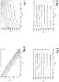
- Each of the diagrams of Figs. 4 - 8 shows seven different curves. These curves correspond to measurements with a fluid of varying composition.
- the fluid was air mixed with C 4 H 10 .
- the bottommost curve of each diagram corresponds to a measurement where the content of C 4 H 10 was 0%
- the second curve from the bottom corresponds to a fluid with a C 4 H 10 -content of 10%
- the third curve to a fluid with a C 4 H 10 -content of 20%
- the topmost curve corresponding to a fluid with a C 4 H 10 -content of 60%.
- Figs. 4 - 8 The temperatures in Figs. 4 - 8 are in arbitrary units.
- DTP 3.25 corresponds to a temperature difference of 0°C.
- the sensor is a thermometer
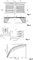
- Figs. 1 and 2 show an example of a thermal flow sensor comprising a heater 1 arranged between a first temperature sensor 2 and a second temperature sensor 3.
- the temperature sensors are thermopiles, albeit the invention can also be carried out with other types of temperature sensors, such as resistive temperature sensors.
- the flow sensor further comprises a substrate 4, such as a semiconductor substrate, wherein the heater 1, the temperature sensors 2, 3 as well as further components are integrated on a surface thereof.
- An opening or recess 5 in substrate 4 has been manufactured e.g. by anisotropic etching and is spanned by a membrane 6.
- the temperature sensors 2, 3 as well as the heater 1 are arranged at least partially on the membrane 6 for good thermal insulation.
- This type of flow sensor is e.g. described in EP 1 426 740 and WO 01/98736 .
- the fluid is led over first temperature sensor 2, then heater 1 and finally second temperature sensor 3.
- Heater 1 is heated by an electric current, advantageously to a temperature that lies at a fixed offset above the temperature of substrate 4.
- Thermal conductance through membrane 6 as well as through the fluid leads to a temperature increase at the inner contacts of the temperature sensors 2, 3, while the outer contacts remain at the bulk temperature of substrate 4.
- the temperature distribution is asymmetric and the temperature TP1 measured by first temperature sensor 2 will generally be lower than the temperature TP2 measured by second temperature sensor 3.
- the temperature difference DTP TP2 - TP1 between the second and the first temperatures TP2, TP1 is a measure of the flow and can be used to determine the flow.
- FIG. 3 A simple block diagram of the flow sensor is shown in Fig. 3 .
- a control unit 7 which e.g. comprises analogue circuitry, such as amplifiers, an A/D-converter as well as digital circuitry. It controls heater 1 and measures the signals from the temperature sensors 2, 3. It processes the signals by accessing lookup tables LUT1, LUT2 and LUT3 in a manner described below, and has an interface 8 through which it can communicate with external circuitry.
- control unit 7 e.g. comprises analogue circuitry, such as amplifiers, an A/D-converter as well as digital circuitry.
- It controls heater 1 and measures the signals from the temperature sensors 2, 3.
- It processes the signals by accessing lookup tables LUT1, LUT2 and LUT3 in a manner described below, and has an interface 8 through which it can communicate with external circuitry.
- Control unit 7 is also connected to a temperature sensor 9 measuring the fluid temperature TF.
- control unit 7 accesses a first lookup-table LUT1, which has two input values, namely the temperature difference DTP as well as the mixture ratio of the fluid, and which provides the flow as an output value. Interpolation of the output values of lookup-table LUT1 allows to calculate the flow for any temperature difference DTP and mixture ratio.
- the mixture ratio required for reading LUT1 can be obtained by the measurement procedure described in the next section.
- Fig. 5 shows the dependence of temperature TP2 at second temperature sensor 3 on the temperature difference DTP for different fluid compositions. As can be seen, the curves are mutually parallel (except for deviations at high temperature differences DTP, i.e. at high flow values, where the flow starts to become turbulent).
- the bottommost curve which was measured for pure air, is roughly at an offset of 0.014 (arbitrary units) below the curve above it, which was measured for a mixture of 90% air and 10% C 4 H 10 , with the offset being independent of DTP.
- the third curve (measured for 80% air and 20% C 4 H 10 ) is roughly 0.027 above the bottommost curve.
- the offset D TP2 x (DTP) - TP2 air between the temperature TP2 x measured for a fluid of unknown mixing ratio between air and C 4 H 10 and the temperature TP2 air measured for pure air at the same temperature difference DTP depends on the mixing ratio only, but not on DTP (i.e. not on the flow).
- Fig. 6 shows the offset D for the curves of Fig. 5 in respect to an earlier calibration measurement carried out with pure air.
- the vertical axis of Fig. 6 is scaled in 10'000 times the units of the vertical axis of Fig. 5 .
- the percentage x of C 4 H 10 can be directly derived from the offset D using a table as follows Table I D x 0 0% 140 10% 270 20% 380 30% 470 40% 540 50% 620 60%
- the mixing ratio of an unknown fluid composition can be measured by the following steps:
- the unknown fluid is measured at a certain flow, i.e. at a certain temperature difference DTP, and the second temperature TP2(DTP) is measured.
- the second temperature TP2 has been used as "single temperature" T in the sense defined above.
- the same procedure can also be carried out with the first temperature TP1, as illustrated in Figs. 7 and 8 .
- the curves in Fig. 7 which show the first temperature TP1 as a function of the temperature difference DTP for air with increasing C 4 H 10 additions, are again parallel (except for small deviations at high flow values where turbulences set it).
- the "second calibration data" relates the temperature offset D as well as the fluid temperature TF to the mixing ratio x.
- lookup-table LUT 3 can be a two-dimensional table having offset D and fluid temperature TF as input values.
- the present method can also be used for measurements on other types of fluids, not only mixtures of air and C 4 H 10 .
- it can be used to measure the mixture ratio of other gas compositions, as well as of liquid compositions.
- the parameter to be measured can be any value depending on the composition, not only the mixing ratio, by storing suitable "second calibration data".
- the mixing ratio x is required for selecting the appropriate part of lookup-table LUT1 when measuring the flow of the fluid.
- this mixing ratio can be obtained from the offset D, or, in other words, offset D may be used as an input value for retrieving the flow from lookup-table LUT1.
- the lookup-tables LUT1, LUT2, LUT3 can, some or all of them, also be arranged outside the flow sensor, in external circuitry.
- the offset D accessible through interface 8 such that a user of the flow sensor can perform composition-dependent operations in external circuitry.
Landscapes
- Chemical & Material Sciences (AREA)
- Physics & Mathematics (AREA)
- General Physics & Mathematics (AREA)
- Health & Medical Sciences (AREA)
- Chemical Kinetics & Catalysis (AREA)
- Electrochemistry (AREA)
- Fluid Mechanics (AREA)
- Life Sciences & Earth Sciences (AREA)
- Analytical Chemistry (AREA)
- Biochemistry (AREA)
- General Health & Medical Sciences (AREA)
- Immunology (AREA)
- Pathology (AREA)
- Measuring Volume Flow (AREA)
- Details Of Flowmeters (AREA)
Description
- The invention relates to a method for measuring a parameter depending on the composition of an unknown fluid by means of a flow sensor, in particular by means of a thermal flow sensor comprising a heater arranged between two temperature sensors.
-
EP 1 426 740 describes a method for measuring a material-dependent parameter, such as a mixture ratio, of a fluid by means of a flow sensor. The fluid is led over a first temperature sensor, a heater and then a second temperature sensor. The temperature difference between the first and the second sensor as well as the temperature of the second sensor are measured. The mixture ratio of the fluid is then calculated by various, fairly complex mathematical transformations. - Document
EP 1 314 966 A1 shows a flow metering method and a flowmeter capable of providing an electric output corresponding to the metered flow rate of metered fluid by an electric circuit including a thermal type flow sensor disposed in a metering flow path and an electric output corresponding to the reference flow rate of the metered fluid by an electric circuit including a reference thermal type flow sensor disposed in a reference flow path allowing the metered flow to flow fleely. - In
US 2004/099057 , for measuring the flow and the thermal conductivity of a fluid, a sensor is used, which has a first temperature detector for measuring a first temperature and a second temperature detector for measuring a second temperature. A heating is arranged between the temperature detectors. Two measured quantities are determined by means of the temperature detectors, a first of which is e.g. a difference between the temperatures and a second one of which is one of the temperatures. By comparing the two measured quantities, the flow and the thermal conductivity of the fluid can be determined. - In
EP 1 538 437 A1 , the concentration of the urea of a urea solution is identified accurately and immediately. A pulse voltage is applied for a predetermined time to a urea concentration identifying sensor heater including a heater and an identifying liquid temperature sensor provided in the vicinity of the heater, a urea solution to be identified is heated by the heater, and the concentration of the urea is identified with a voltage output difference V0 corresponding to a temperature difference between an initial temperature and a peak temperature in the identifying liquid temperature sensor. - Hence, it is a general object of the invention to provide a method of the type mentioned above that allows to measure a parameter depending on the composition of an unknown fluid that obviates the need for complicated mathematical transformations.
- This problem is solved by the method of claim 1.
- Accordingly, as in the prior art, the unknown fluid is led over the first temperature sensor, then the heater, and finally the second temperature sensor. The difference DTP = TP2 - TP1 between the temperature TP2 at the second temperature sensor and the temperature TP1 at the first temperature sensor is measured, as well as a "single temperature T". The single temperature T is equal to k1·TP1 + k2·TP2 with k1 ≠ -k2. Advantageously T = TP1 or T = TP2 is used for computational simplicity, but any linear combination of the two temperatures can be used.
- Now, "first calibration data" is retrieved, e.g. from a memory. This first calibration data was obtained from a calibration measurement carried out with a reference fluid of known composition. The first calibration data is such that it allows to calculate the value of the single temperature that the reference fluid exhibited at a given temperature difference, and in particular at the temperature difference DTP measured for the unknown fluid. This single temperature of the reference fluid at DTP is called the "reference temperature Tref(DTP)".
- In a next step, the "temperature offset" D = T - Tref(DTP) is calculated, i.e. the difference between the single temperature T measured for the unknown fluid and the single temperature of the reference fluid at the measured temperature difference DTP.
- As it has been found, the temperature offset D is a direct measure of the composition of the unknown fluid, independent of the temperature difference DTP and-therefore independent of the flow of the fluid. Hence, the temperature offset D can be used to easily calculate the desired parameter, e.g. by means of a lookup-table that contains the data required for calculating the parameter from the temperature offset D.
- Since the temperature offset D does not depend on the flow but merely on the composition of the fluid, the present method can be used to determine the parameter at any non-zero flow as well as for zero flow without requiring any flow-dependent corrections.
- In a typical application, the unknown fluid is a mixture of two known fluids and the parameter to be determined from the temperature offset D is the mixture ratio of the two fluids.
- The present invention can be used for determining a composition-dependent parameter of any type of fluid, in particular of liquids as well as of gases.
- The invention will be better understood and objects other than those set forth above will become apparent when consideration is given to the following detailed description thereof. Such description makes reference to the annexed drawings, wherein:
-
Fig. 1 is a top view of the heater and the temperature sensors of a flow sensor, -
Fig. 2 is a sectional view along line II-II ofFig. 1 , -
Fig. 3 is a simplified block diagram of the flow sensor, -
Fig. 4 shows the dependence of the temperature difference DTP on the flow of the fluid for differing fluid compositions, -
Fig. 5 shows the dependence of the second temperature TP2 on the temperature difference DTP, -
Fig. 6 shows the dependence of the offset D on the temperature difference DTP as calculated fromFig. 5 , -
Fig. 7 shows the dependence of the first temperature TP1 on the temperature difference DTP, and -
Fig. 8 shows the dependence of the offset D on the temperature difference DTP as calculated fromFig. 8 . - The term "unknown fluid" designates the fluid whose composition is not known. For example, the unknown fluid is a mixture of two known fluids with unknown mixture ratio.
- The term "fluid temperature TF" designates the temperature of the fluid in the absence of any heating contribution by the heater, e.g. a temperature measured at a fairly large distance before the heater.
- Each of the diagrams of
Figs. 4 - 8 shows seven different curves. These curves correspond to measurements with a fluid of varying composition. In the specific example shown here, the fluid was air mixed with C4H10. The bottommost curve of each diagram corresponds to a measurement where the content of C4H10 was 0%, the second curve from the bottom corresponds to a fluid with a C4H10-content of 10%, the third curve to a fluid with a C4H10-content of 20%, etc., with the topmost curve corresponding to a fluid with a C4H10-content of 60%. - The temperatures in
Figs. 4 - 8 are in arbitrary units. InFig. 4 , DTP = 3.25 corresponds to a temperature difference of 0°C. -
Figs. 1 and 2 show an example of a thermal flow sensor comprising a heater 1 arranged between afirst temperature sensor 2 and asecond temperature sensor 3. In the present embodiment, the temperature sensors are thermopiles, albeit the invention can also be carried out with other types of temperature sensors, such as resistive temperature sensors. The flow sensor further comprises asubstrate 4, such as a semiconductor substrate, wherein the heater 1, thetemperature sensors recess 5 insubstrate 4 has been manufactured e.g. by anisotropic etching and is spanned by amembrane 6. Thetemperature sensors membrane 6 for good thermal insulation. - This type of flow sensor is e.g. described in
EP 1 426 740 andWO 01/98736 first temperature sensor 2, then heater 1 and finallysecond temperature sensor 3. Heater 1 is heated by an electric current, advantageously to a temperature that lies at a fixed offset above the temperature ofsubstrate 4. Thermal conductance throughmembrane 6 as well as through the fluid leads to a temperature increase at the inner contacts of thetemperature sensors substrate 4. In the presence of a non-zero flow, however, the temperature distribution is asymmetric and the temperature TP1 measured byfirst temperature sensor 2 will generally be lower than the temperature TP2 measured bysecond temperature sensor 3. - The temperature difference DTP = TP2 - TP1 between the second and the first temperatures TP2, TP1 is a measure of the flow and can be used to determine the flow.
- A simple block diagram of the flow sensor is shown in
Fig. 3 . As can be seen, it comprises acontrol unit 7, which e.g. comprises analogue circuitry, such as amplifiers, an A/D-converter as well as digital circuitry. It controls heater 1 and measures the signals from thetemperature sensors -
Control unit 7 is also connected to atemperature sensor 9 measuring the fluid temperature TF. - Advantageously, all or at least part of the electronic components shown in
Fig. 3 are integrated onsemiconductor substrate 4, but part or all of these components may also be implemented as external circuitry. - To measure the flow of the fluid, as mentioned, the temperature difference DTP is determined. As can be seen from
Fig. 4 , the relationship between the flow and the temperature difference DTP is non-linear and depends on the mixture ratio of the fluid. Therefore,control unit 7 accesses a first lookup-table LUT1, which has two input values, namely the temperature difference DTP as well as the mixture ratio of the fluid, and which provides the flow as an output value. Interpolation of the output values of lookup-table LUT1 allows to calculate the flow for any temperature difference DTP and mixture ratio. - The mixture ratio required for reading LUT1 can be obtained by the measurement procedure described in the next section.
-
Fig. 5 shows the dependence of temperature TP2 atsecond temperature sensor 3 on the temperature difference DTP for different fluid compositions. As can be seen, the curves are mutually parallel (except for deviations at high temperature differences DTP, i.e. at high flow values, where the flow starts to become turbulent). - For example, the bottommost curve, which was measured for pure air, is roughly at an offset of 0.014 (arbitrary units) below the curve above it, which was measured for a mixture of 90% air and 10% C4H10, with the offset being independent of DTP. And the third curve (measured for 80% air and 20% C4H10) is roughly 0.027 above the bottommost curve.
- Hence, in the present example, the offset D = TP2x(DTP) - TP2air between the temperature TP2x measured for a fluid of unknown mixing ratio between air and C4H10 and the temperature TP2air measured for pure air at the same temperature difference DTP depends on the mixing ratio only, but not on DTP (i.e. not on the flow).
- This is illustrated by
Fig. 6 , which shows the offset D for the curves ofFig. 5 in respect to an earlier calibration measurement carried out with pure air. (Note: The vertical axis ofFig. 6 is scaled in 10'000 times the units of the vertical axis ofFig. 5 .) As can be seen, the percentage x of C4H10 can be directly derived from the offset D using a table as followsTable I D x 0 0% 140 10% 270 20% 380 30% 470 40% 540 50% 620 60% - Hence, the mixing ratio of an unknown fluid composition can be measured by the following steps:
- First, a reference measurement is made for varying flows of a fluid of known composition. This reference measurement can be used to derive the dependence of TP2ref on the temperature difference DTP. This dependence is stored as the "first calibration data", e.g. in a lookup table LUT2 of the sensor (
Fig. 3 ). - Then, the unknown fluid is measured at a certain flow, i.e. at a certain temperature difference DTP, and the second temperature TP2(DTP) is measured. The calibration data in LUT2 is used to calculate the second temperature TP2ref(DTP) that the reference fluid had (or would have had) at the same temperature difference DTP, and the offset D = TP2(DTP) - TP2ref(DTP) is calculated.
- From table I above, which may e.g. be stored as "second calibration data" in a third lookup table LUT3 of the sensor (or of a device external to the sensor), it is now possible to calculate the composition x using interpolation.
- In
Figs. 5 and 6 , the second temperature TP2 has been used as "single temperature" T in the sense defined above. However, it must be noted that the same procedure can also be carried out with the first temperature TP1, as illustrated inFigs. 7 and 8 . As can be seen, the curves inFig. 7 , which show the first temperature TP1 as a function of the temperature difference DTP for air with increasing C4H10 additions, are again parallel (except for small deviations at high flow values where turbulences set it). - Hence, the same kind of calculation can be carried out for the first temperature TP1.
- As mentioned above, the "single temperature" T can not only be TP1 or TP2, but also any linear combination thereof, in particular TP1 + TP2. (Using T = TP1 - TP2, however, makes little sense since, in this case, the offset D would be constantly 0).
- Experimental evidence shows that the offset D also depends, to some slight degree, on the fluid temperature TF. Hence, advantageously, the "second calibration data" relates the temperature offset D as well as the fluid temperature TF to the mixing ratio x. For example, lookup-
table LUT 3 can be a two-dimensional table having offset D and fluid temperature TF as input values. - The present method can also be used for measurements on other types of fluids, not only mixtures of air and C4H10. For example, it can be used to measure the mixture ratio of other gas compositions, as well as of liquid compositions.
- Also, the parameter to be measured can be any value depending on the composition, not only the mixing ratio, by storing suitable "second calibration data".
- As mentioned above, the mixing ratio x is required for selecting the appropriate part of lookup-table LUT1 when measuring the flow of the fluid. As can be seen know, this mixing ratio can be obtained from the offset D, or, in other words, offset D may be used as an input value for retrieving the flow from lookup-table LUT1.
- The lookup-tables LUT1, LUT2, LUT3 can, some or all of them, also be arranged outside the flow sensor, in external circuitry. In a particularly advantageous embodiment the offset D accessible through interface 8 such that a user of the flow sensor can perform composition-dependent operations in external circuitry.
- As it has been mentioned, deviations from the described behavior start to occur when the flow of the fluid starts to become turbulent. Hence, advantageously, the temperature difference DTP and the single temperature T are measured for laminar flows.
- While there are shown and described presently preferred embodiments of the invention, it is to be distinctly understood that the invention is not limited thereto but may be otherwise variously embodied and practiced within the scope of the following claims.
Claims (11)
- A method for determining a parameter depending on the composition of an unknown fluid by means of a flow sensor, wherein said flow sensor comprises a heater (1) arranged between a first and a second temperature sensor (2, 3), said method comprising the steps of
leading said unknown fluid over said first temperature sensor (2), said heater (1) and said second temperature sensor (3),
measuring a temperature difference DTP between a temperature TP2 at said second temperature sensor (3) and a temperature TP1 at said first temperature sensor (2) as well as a single temperature T, which single temperature is equal to k1·TP1 + k2·TP2 with k1 ≠ -k2,
retrieving first calibration data (LUT2), which first calibration data was obtained from a calibration measurement carried out with a reference fluid of known composition, and which first calibration data is such that it allows to calculate the value of the single temperature that the reference fluid exhibited at a given temperature difference,
using said first calibration data (LUT2) to calculate a reference temperature Tref(DTP) equal to the single temperature of said reference fluid at said temperature difference DTP, and
deriving said parameter from a temperature offset D = T - Tref(DTP) between said single temperature T measured for said unknown fluid at said temperature difference DTP and the single temperature of said reference fluid at said temperature difference DTP. - The method of claim 1 wherein said single temperature T is the temperature measured by said first temperature sensor (2).
- The method of claim 1 wherein said single temperature T is the temperature measured by said second temperature sensor (3).
- The method of any of the preceding claims comprising the step of providing second calibration data (LUT3) for calculating said parameter from said temperature offset D.
- The method of claim 4 wherein said second calibration data relates said temperature offset D and a fluid temperature TF to said parameter.
- The method of any of the preceding claims wherein in said step of deriving said parameter from the offset D said parameter is determined as a function of said temperature offset D and a fluid temperature TF.
- The method of any of the preceding claims wherein said unknown fluid is a mixture of two known fluids and wherein said parameter is a mixture ratio of said known fluids.
- The method of any of the preceding claims wherein said flow sensor comprises a substrate (4) having an opening or recess (5) and a membrane (6) arranged over said opening or recess (5), and wherein said temperature sensors (2, 3) and said heater (1) are arranged at least partially on said membrane (6).
- The method of any of the preceding claims wherein said temperature difference DTP and said single temperature T are measured at non-zero flow.
- The method of any of the preceding claims wherein said temperature difference DTP and said single temperature T are measured for a laminar flow of said unknown fluid.
- The method of any of the preceding claims wherein said flow sensor comprises an interface (8) to external circuitry and said method comprises the step of providing said offset D at said interface.
Priority Applications (2)
| Application Number | Priority Date | Filing Date | Title |
|---|---|---|---|
| EP08017691.0A EP2175246B1 (en) | 2008-10-09 | 2008-10-09 | A method for measuring a fluid composition parameter by means of a flow sensor |
| US12/583,747 US8408050B2 (en) | 2008-10-09 | 2009-08-25 | Method for measuring a fluid composition parameter by means of a flow sensor |
Applications Claiming Priority (1)
| Application Number | Priority Date | Filing Date | Title |
|---|---|---|---|
| EP08017691.0A EP2175246B1 (en) | 2008-10-09 | 2008-10-09 | A method for measuring a fluid composition parameter by means of a flow sensor |
Publications (2)
| Publication Number | Publication Date |
|---|---|
| EP2175246A1 EP2175246A1 (en) | 2010-04-14 |
| EP2175246B1 true EP2175246B1 (en) | 2017-07-19 |
Family
ID=40225486
Family Applications (1)
| Application Number | Title | Priority Date | Filing Date |
|---|---|---|---|
| EP08017691.0A Active EP2175246B1 (en) | 2008-10-09 | 2008-10-09 | A method for measuring a fluid composition parameter by means of a flow sensor |
Country Status (2)
| Country | Link |
|---|---|
| US (1) | US8408050B2 (en) |
| EP (1) | EP2175246B1 (en) |
Cited By (1)
| Publication number | Priority date | Publication date | Assignee | Title |
|---|---|---|---|---|
| DE102022127043A1 (en) | 2022-10-15 | 2024-04-18 | Sensirion Ag | Drift compensation for a sensor measuring the concentration of a substance in a fluid |
Families Citing this family (14)
| Publication number | Priority date | Publication date | Assignee | Title |
|---|---|---|---|---|
| US8943887B2 (en) * | 2009-12-18 | 2015-02-03 | Waters Technologies Corporation | Thermal-based flow sensing apparatuses and methods for high-performance liquid chromatography |
| DE102012001060A1 (en) * | 2011-10-24 | 2013-04-25 | Hydrometer Gmbh | Method for correcting offset drift effects of a thermal measuring device, thermal measuring device and gas flow meter |
| EP2887057A1 (en) | 2013-12-17 | 2015-06-24 | Sensirion AG | Device and method of humidity compensated gas concentration monitoring by thermal conductivity measurements |
| EP2894464B1 (en) | 2014-01-10 | 2021-11-10 | Sensirion AG | Microsensor for gas flow and concentration measurements |
| US9612146B2 (en) | 2014-02-07 | 2017-04-04 | Honeywell International, Inc. | Airflow sensor with dust reduction |
| EP3029429B1 (en) | 2014-12-04 | 2020-10-07 | Sensirion AG | Determination of fluid composition in a mass flow controller |
| GB2553681B (en) | 2015-01-07 | 2019-06-26 | Homeserve Plc | Flow detection device |
| GB201501935D0 (en) | 2015-02-05 | 2015-03-25 | Tooms Moore Consulting Ltd And Trow Consulting Ltd | Water flow analysis |
| EP3118711B1 (en) | 2015-07-17 | 2021-01-13 | Sensirion AG | Inlet pressure perturbation insensitive mass flow controller |
| RU2651931C2 (en) * | 2016-06-08 | 2018-04-24 | Общество с ограниченной ответственностью "Объединенная Компания РУСАЛ Инженерно-технологический центр" | Device and method for determination of electrolyte composition |
| EP3348969B1 (en) | 2017-01-12 | 2020-11-18 | Sensirion AG | Measurement of a fluid parameter and sensor device therefore |
| EP3421947B1 (en) | 2017-06-30 | 2019-08-07 | Sensirion AG | Operation method for flow sensor device |
| AU2019205103B2 (en) | 2018-01-05 | 2021-11-04 | GS Elektromedizinische Geräte G. Stemple GmbH | Evaluation arrangement for a thermal gas sensor, method and computer program product |
| CA3087632A1 (en) | 2018-01-05 | 2019-07-11 | Sophie Billat | Gas sensor and method for operating the gas sensor |
Family Cites Families (37)
| Publication number | Priority date | Publication date | Assignee | Title |
|---|---|---|---|---|
| NL177629C (en) | 1979-07-09 | 1985-10-16 | Brooks Instr Bv | DIRECTIONAL SENSITIVE FLOW SPEEDOMETER. |
| JPS58501094A (en) | 1981-07-13 | 1983-07-07 | バテル メモリアル インステイチユ−ト | A method for determining at least one instantaneous parameter of a fluid associated with heat exchange of a probe immersed in the fluid, and an apparatus for carrying out the method. |
| JPS601525A (en) | 1983-06-20 | 1985-01-07 | Nippon Soken Inc | Semiconductor type flow-rate detecting device |
| US4712996A (en) | 1986-11-21 | 1987-12-15 | Emerson Electric Co. | Gas burner control system with mass flow sensor |
| US4909078A (en) | 1987-10-14 | 1990-03-20 | Rosemount Inc. | Fluid flow detector |
| US4961348A (en) | 1988-12-16 | 1990-10-09 | Ulrich Bonne | Flowmeter fluid composition correction |
| US4885938A (en) | 1988-12-16 | 1989-12-12 | Honeywell Inc. | Flowmeter fluid composition correction |
| GB8903744D0 (en) | 1989-02-18 | 1989-04-05 | Endress & Hauser Ltd | Flowmeter |
| US5237523A (en) | 1990-07-25 | 1993-08-17 | Honeywell Inc. | Flowmeter fluid composition and temperature correction |
| DE69109236T2 (en) | 1990-11-09 | 1996-01-11 | Hewlett Packard Co | Methods and systems for identifying liquids and determining flow. |
| DE4219454C2 (en) * | 1992-06-13 | 1995-09-28 | Bosch Gmbh Robert | Mass flow sensor |
| WO1995002164A1 (en) | 1993-07-07 | 1995-01-19 | Ic Sensors, Inc. | Pulsed thermal flow sensor system |
| US5460841A (en) | 1993-07-08 | 1995-10-24 | Chiquita Brands, Inc. | Process for ripening bananas and other produce |
| DE4418207C1 (en) | 1994-05-25 | 1995-06-22 | Siemens Ag | Thermal sensor or actuator in semiconductor material |
| US5980102A (en) | 1994-06-20 | 1999-11-09 | Columbia Gas Of Ohio | Method for measuring physical characteristics in a pipeline without tapping |
| US5515714A (en) | 1994-11-17 | 1996-05-14 | General Motors Corporation | Vapor composition and flow sensor |
| JPH0972763A (en) | 1995-09-07 | 1997-03-18 | Ricoh Co Ltd | Microsensor |
| JP3366818B2 (en) | 1997-01-16 | 2003-01-14 | 株式会社日立製作所 | Thermal air flow meter |
| JP3433124B2 (en) | 1998-12-15 | 2003-08-04 | 株式会社日立製作所 | Thermal air flow sensor |
| JP4050857B2 (en) | 1999-04-27 | 2008-02-20 | 矢崎総業株式会社 | Fluid discrimination device and flow rate measuring device |
| DE10082701D2 (en) | 1999-09-09 | 2002-08-14 | Sensirion Ag Zuerich | Method and device for precision mass flow measurement |
| US6650325B1 (en) | 1999-12-06 | 2003-11-18 | Nvidia Corporation | Method, apparatus and article of manufacture for boustrophedonic rasterization |
| CH694474A5 (en) | 2000-06-23 | 2005-01-31 | Sensirion Ag | Gas meter and use of the gas meter. |
| WO2002010693A1 (en) * | 2000-07-31 | 2002-02-07 | Mitsui Mining & Smelting Co., Ltd. | Flow metering method and flowmeter |
| EP1396705B1 (en) * | 2002-08-27 | 2016-12-21 | Sensirion Holding AG | Flow detector with through-holes and and process for making the same |
| JP4108681B2 (en) | 2002-09-10 | 2008-06-25 | 三井金属鉱業株式会社 | Urea concentration identification device, urea concentration identification method, automobile exhaust gas reduction device and automobile exhaust gas reduction method using the same |
| EP1426740B1 (en) * | 2002-11-27 | 2014-11-19 | Sensirion Holding AG | Device for measuring the flow and at least one material parameter of a fluid |
| ES2310057B1 (en) * | 2004-07-19 | 2009-11-17 | Oryzon Genomics, S.A. | METHOD OF MOLECULAR ANALYSIS AND TREATMENT IN DEMENTIA OF LEWY BODIES. |
| US20090123361A1 (en) * | 2005-02-03 | 2009-05-14 | Amminex A/S | High Density Storage of Ammonia |
| JP2008546968A (en) | 2005-06-29 | 2008-12-25 | アムミネクス・アー/エス | Method and apparatus for the safe and controlled delivery of ammonia from a solid ammonia storage medium |
| EP1772717B1 (en) | 2005-10-04 | 2011-05-11 | Sensirion Holding AG | Pressure or gas sensor and sensing method using nano-cavities |
| DE102005062120B4 (en) * | 2005-12-23 | 2016-06-09 | Robert Bosch Gmbh | Method and device for monitoring an exhaust aftertreatment system |
| DE602006019548D1 (en) * | 2006-03-31 | 2011-02-24 | Sensirion Holding Ag | Flow sensor with thermocouples |
| US8015801B2 (en) * | 2006-09-18 | 2011-09-13 | Ford Global Technologies, Llc | Management of a plurality of reductants for selective catalytic reduction |
| EP2107932A2 (en) * | 2006-12-22 | 2009-10-14 | Amminex A/S | Method and device for safe storage and use of volatile ammonia storage materials |
| EP1977817B1 (en) * | 2007-03-30 | 2010-11-24 | Amminex A/S | A system for storing ammonia in and releasing ammonia from a storage material and method for storing and releasing ammonia |
| EP2107347B1 (en) * | 2008-04-04 | 2016-08-31 | Sensirion AG | Flow detector with a housing |
-
2008
- 2008-10-09 EP EP08017691.0A patent/EP2175246B1/en active Active
-
2009
- 2009-08-25 US US12/583,747 patent/US8408050B2/en active Active
Non-Patent Citations (1)
| Title |
|---|
| None * |
Cited By (1)
| Publication number | Priority date | Publication date | Assignee | Title |
|---|---|---|---|---|
| DE102022127043A1 (en) | 2022-10-15 | 2024-04-18 | Sensirion Ag | Drift compensation for a sensor measuring the concentration of a substance in a fluid |
Also Published As
| Publication number | Publication date |
|---|---|
| US20100089118A1 (en) | 2010-04-15 |
| EP2175246A1 (en) | 2010-04-14 |
| US8408050B2 (en) | 2013-04-02 |
Similar Documents
| Publication | Publication Date | Title |
|---|---|---|
| EP2175246B1 (en) | A method for measuring a fluid composition parameter by means of a flow sensor | |
| US8225652B2 (en) | Thermal flow meter measuring flow rate based on temperature difference measurement and driving energy of the heater | |
| US8504311B2 (en) | Method and mass flow controller for enhanced operating range | |
| US7363182B2 (en) | System and method for mass flow detection device calibration | |
| TWI444799B (en) | Calibration method for flow rate controller and flow rate measuring device, calibration system for flow rate controller, and semiconductor production apparatus | |
| US11371894B2 (en) | Method for the in-situ calibration of a thermometer | |
| US7191645B2 (en) | Dynamic mixed gas flowmeter | |
| US9921588B2 (en) | Determination of fluid composition in a mass flow controller | |
| US11474056B2 (en) | Sensor for determining the thermal capacity of natural gas | |
| WO2000065315A1 (en) | Thermal flow sensor, method and apparatus for identifying fluid, flow sensor, and method and apparatus for flow measurement | |
| US7054767B2 (en) | Thermal mass flowmeter apparatus and method with temperature correction | |
| JPH08233792A (en) | Method and equimpment for measurement and control of flow rate and pressure | |
| US20140311237A1 (en) | Method for detecting a flow property of a flowing fluid medium | |
| JP5420456B2 (en) | Calorific value calculation formula creation system, calorific value calculation formula creation method, calorific value measurement system, and calorific value measurement method | |
| JP5421832B2 (en) | Calorific value calculation formula creation system, calorific value calculation formula creation method, calorific value measurement system, and calorific value measurement method | |
| EP3153854B1 (en) | Determination of volumetric flow rate of a gas in a gas flow | |
| JP2011209152A (en) | Flowmeter | |
| US8950273B2 (en) | Method and thermal, flow measuring device for determining and/or monitoring at least one variable dependent on at least the chemical composition of a measured medium | |
| JP5192431B2 (en) | Gas property measurement system | |
| JPH11183231A (en) | Integrating flow meter and gas meter using it | |
| JP5275876B2 (en) | Heater and gas property measurement system | |
| JP5165627B2 (en) | Physical property value measuring system and physical property value measuring method | |
| JP3193241B2 (en) | Measuring device | |
| JP3719802B2 (en) | Multipoint flow meter | |
| JPH05164721A (en) | Humidity detecting circuit |
Legal Events
| Date | Code | Title | Description |
|---|---|---|---|
| PUAI | Public reference made under article 153(3) epc to a published international application that has entered the european phase |
Free format text: ORIGINAL CODE: 0009012 |
|
| AK | Designated contracting states |
Kind code of ref document: A1 Designated state(s): AT BE BG CH CY CZ DE DK EE ES FI FR GB GR HR HU IE IS IT LI LT LU LV MC MT NL NO PL PT RO SE SI SK TR |
|
| AX | Request for extension of the european patent |
Extension state: AL BA MK RS |
|
| 17P | Request for examination filed |
Effective date: 20101012 |
|
| AKX | Designation fees paid |
Designated state(s): DE GB IT |
|
| 17Q | First examination report despatched |
Effective date: 20160609 |
|
| REG | Reference to a national code |
Ref country code: DE Ref legal event code: R079 Ref document number: 602008051144 Country of ref document: DE Free format text: PREVIOUS MAIN CLASS: G01F0001680000 Ipc: G01N0027180000 |
|
| GRAP | Despatch of communication of intention to grant a patent |
Free format text: ORIGINAL CODE: EPIDOSNIGR1 |
|
| RIC1 | Information provided on ipc code assigned before grant |
Ipc: G01N 27/18 20060101AFI20170330BHEP Ipc: G01F 1/692 20060101ALI20170330BHEP |
|
| INTG | Intention to grant announced |
Effective date: 20170424 |
|
| GRAS | Grant fee paid |
Free format text: ORIGINAL CODE: EPIDOSNIGR3 |
|
| GRAA | (expected) grant |
Free format text: ORIGINAL CODE: 0009210 |
|
| AK | Designated contracting states |
Kind code of ref document: B1 Designated state(s): DE GB IT |
|
| REG | Reference to a national code |
Ref country code: GB Ref legal event code: FG4D |
|
| REG | Reference to a national code |
Ref country code: DE Ref legal event code: R096 Ref document number: 602008051144 Country of ref document: DE |
|
| REG | Reference to a national code |
Ref country code: DE Ref legal event code: R097 Ref document number: 602008051144 Country of ref document: DE |
|
| PLBE | No opposition filed within time limit |
Free format text: ORIGINAL CODE: 0009261 |
|
| STAA | Information on the status of an ep patent application or granted ep patent |
Free format text: STATUS: NO OPPOSITION FILED WITHIN TIME LIMIT |
|
| 26N | No opposition filed |
Effective date: 20180420 |
|
| P01 | Opt-out of the competence of the unified patent court (upc) registered |
Effective date: 20230602 |
|
| PGFP | Annual fee paid to national office [announced via postgrant information from national office to epo] |
Ref country code: GB Payment date: 20231025 Year of fee payment: 16 |
|
| PGFP | Annual fee paid to national office [announced via postgrant information from national office to epo] |
Ref country code: IT Payment date: 20231031 Year of fee payment: 16 Ref country code: DE Payment date: 20231018 Year of fee payment: 16 |