EP2175191A1 - Combinational inset lamp exempt from a shielding cylinder - Google Patents
Combinational inset lamp exempt from a shielding cylinder Download PDFInfo
- Publication number
- EP2175191A1 EP2175191A1 EP08165978A EP08165978A EP2175191A1 EP 2175191 A1 EP2175191 A1 EP 2175191A1 EP 08165978 A EP08165978 A EP 08165978A EP 08165978 A EP08165978 A EP 08165978A EP 2175191 A1 EP2175191 A1 EP 2175191A1
- Authority
- EP
- European Patent Office
- Prior art keywords
- cover
- lamp
- insulation cover
- inset
- combinational
- Prior art date
- Legal status (The legal status is an assumption and is not a legal conclusion. Google has not performed a legal analysis and makes no representation as to the accuracy of the status listed.)
- Withdrawn
Links
- 238000009413 insulation Methods 0.000 claims abstract description 54
- 230000017525 heat dissipation Effects 0.000 claims description 34
- 239000000758 substrate Substances 0.000 claims description 6
- 230000005540 biological transmission Effects 0.000 claims description 3
- OKTJSMMVPCPJKN-UHFFFAOYSA-N Carbon Chemical compound [C] OKTJSMMVPCPJKN-UHFFFAOYSA-N 0.000 abstract description 2
- 229910052799 carbon Inorganic materials 0.000 abstract description 2
- 230000007613 environmental effect Effects 0.000 abstract description 2
- 238000003780 insertion Methods 0.000 description 3
- 230000037431 insertion Effects 0.000 description 3
- 230000007547 defect Effects 0.000 description 2
- 238000012986 modification Methods 0.000 description 2
- 230000004048 modification Effects 0.000 description 2
- WFKWXMTUELFFGS-UHFFFAOYSA-N tungsten Chemical compound [W] WFKWXMTUELFFGS-UHFFFAOYSA-N 0.000 description 2
- 229910052721 tungsten Inorganic materials 0.000 description 2
- 239000010937 tungsten Substances 0.000 description 2
- 230000001133 acceleration Effects 0.000 description 1
- 238000005286 illumination Methods 0.000 description 1
- 238000009434 installation Methods 0.000 description 1
- 239000000463 material Substances 0.000 description 1
- 238000000034 method Methods 0.000 description 1
Images


Classifications
-
- F—MECHANICAL ENGINEERING; LIGHTING; HEATING; WEAPONS; BLASTING
- F21—LIGHTING
- F21S—NON-PORTABLE LIGHTING DEVICES; SYSTEMS THEREOF; VEHICLE LIGHTING DEVICES SPECIALLY ADAPTED FOR VEHICLE EXTERIORS
- F21S8/00—Lighting devices intended for fixed installation
- F21S8/02—Lighting devices intended for fixed installation of recess-mounted type, e.g. downlighters
- F21S8/026—Lighting devices intended for fixed installation of recess-mounted type, e.g. downlighters intended to be recessed in a ceiling or like overhead structure, e.g. suspended ceiling
-
- F—MECHANICAL ENGINEERING; LIGHTING; HEATING; WEAPONS; BLASTING
- F21—LIGHTING
- F21V—FUNCTIONAL FEATURES OR DETAILS OF LIGHTING DEVICES OR SYSTEMS THEREOF; STRUCTURAL COMBINATIONS OF LIGHTING DEVICES WITH OTHER ARTICLES, NOT OTHERWISE PROVIDED FOR
- F21V21/00—Supporting, suspending, or attaching arrangements for lighting devices; Hand grips
- F21V21/02—Wall, ceiling, or floor bases; Fixing pendants or arms to the bases
- F21V21/04—Recessed bases
-
- F—MECHANICAL ENGINEERING; LIGHTING; HEATING; WEAPONS; BLASTING
- F21—LIGHTING
- F21V—FUNCTIONAL FEATURES OR DETAILS OF LIGHTING DEVICES OR SYSTEMS THEREOF; STRUCTURAL COMBINATIONS OF LIGHTING DEVICES WITH OTHER ARTICLES, NOT OTHERWISE PROVIDED FOR
- F21V29/00—Protecting lighting devices from thermal damage; Cooling or heating arrangements specially adapted for lighting devices or systems
- F21V29/50—Cooling arrangements
- F21V29/70—Cooling arrangements characterised by passive heat-dissipating elements, e.g. heat-sinks
- F21V29/74—Cooling arrangements characterised by passive heat-dissipating elements, e.g. heat-sinks with fins or blades
- F21V29/77—Cooling arrangements characterised by passive heat-dissipating elements, e.g. heat-sinks with fins or blades with essentially identical diverging planar fins or blades, e.g. with fan-like or star-like cross-section
- F21V29/773—Cooling arrangements characterised by passive heat-dissipating elements, e.g. heat-sinks with fins or blades with essentially identical diverging planar fins or blades, e.g. with fan-like or star-like cross-section the planes containing the fins or blades having the direction of the light emitting axis
-
- F—MECHANICAL ENGINEERING; LIGHTING; HEATING; WEAPONS; BLASTING
- F21—LIGHTING
- F21V—FUNCTIONAL FEATURES OR DETAILS OF LIGHTING DEVICES OR SYSTEMS THEREOF; STRUCTURAL COMBINATIONS OF LIGHTING DEVICES WITH OTHER ARTICLES, NOT OTHERWISE PROVIDED FOR
- F21V29/00—Protecting lighting devices from thermal damage; Cooling or heating arrangements specially adapted for lighting devices or systems
- F21V29/50—Cooling arrangements
- F21V29/70—Cooling arrangements characterised by passive heat-dissipating elements, e.g. heat-sinks
- F21V29/83—Cooling arrangements characterised by passive heat-dissipating elements, e.g. heat-sinks the elements having apertures, ducts or channels, e.g. heat radiation holes
-
- F—MECHANICAL ENGINEERING; LIGHTING; HEATING; WEAPONS; BLASTING
- F21—LIGHTING
- F21V—FUNCTIONAL FEATURES OR DETAILS OF LIGHTING DEVICES OR SYSTEMS THEREOF; STRUCTURAL COMBINATIONS OF LIGHTING DEVICES WITH OTHER ARTICLES, NOT OTHERWISE PROVIDED FOR
- F21V15/00—Protecting lighting devices from damage
- F21V15/01—Housings, e.g. material or assembling of housing parts
-
- F—MECHANICAL ENGINEERING; LIGHTING; HEATING; WEAPONS; BLASTING
- F21—LIGHTING
- F21V—FUNCTIONAL FEATURES OR DETAILS OF LIGHTING DEVICES OR SYSTEMS THEREOF; STRUCTURAL COMBINATIONS OF LIGHTING DEVICES WITH OTHER ARTICLES, NOT OTHERWISE PROVIDED FOR
- F21V23/00—Arrangement of electric circuit elements in or on lighting devices
- F21V23/06—Arrangement of electric circuit elements in or on lighting devices the elements being coupling devices, e.g. connectors
-
- F—MECHANICAL ENGINEERING; LIGHTING; HEATING; WEAPONS; BLASTING
- F21—LIGHTING
- F21V—FUNCTIONAL FEATURES OR DETAILS OF LIGHTING DEVICES OR SYSTEMS THEREOF; STRUCTURAL COMBINATIONS OF LIGHTING DEVICES WITH OTHER ARTICLES, NOT OTHERWISE PROVIDED FOR
- F21V27/00—Cable-stowing arrangements structurally associated with lighting devices, e.g. reels
-
- F—MECHANICAL ENGINEERING; LIGHTING; HEATING; WEAPONS; BLASTING
- F21—LIGHTING
- F21Y—INDEXING SCHEME ASSOCIATED WITH SUBCLASSES F21K, F21L, F21S and F21V, RELATING TO THE FORM OR THE KIND OF THE LIGHT SOURCES OR OF THE COLOUR OF THE LIGHT EMITTED
- F21Y2115/00—Light-generating elements of semiconductor light sources
- F21Y2115/10—Light-emitting diodes [LED]
Definitions
- This invention relates to a combinational recessed lamp exempt from a shielding cylinder.
- An inset lamp is a lamp installed on the ceiling, and a luminous source, such as a tungsten lamp, an energy-saving light bulb, or a LED lamp, is provided in a shielding cylinder.
- the lamp is recessed into the ceiling, so it looks artistic and doesn't hurt people's eyes, thereby being widely used for indoor illumination.
- the recessed lamp must work with the shielding cylinder and may thus be arranged on the ceiling, and the cost increases and the materials of shielding cylinder are wasted.
- This invention relates to a combinational recessed lamp exempt from a shielding cylinder that may be embed into an inset hole on the ceiling and comprises a light-source body.
- the light-source body is covered by an insulation cover.
- An outer disk cover is provided stretching outwards and transversally from the outer circumference of a lower part of the insulation cover. Further, at least opposite two sides of the outer circumferential wall of insulation cover that are respectively provided outwards with an elastic clamping flake that is removable.
- the outer disk cover and the elastic clamping flake that work with each other may be used to directly wedge the lamp according to this invention onto the ceiling.
- the lamp that may be provided without any shielding cylinder is removable and replaceable conveniently for achievement of the advantages of carbon decrease, energy saving, and environmental protection.
- an inset lamp in a preferred embodiment of this invention comprises a light-source body 10, a lamp cover 20, an insulation cover 30, and an extension cover 40.
- the light-source body 10 further comprises a heat dissipation part 11, a drive circuit board 12, and a LED lamp board 13.
- the heat dissipation part 11 is metallic and is arranged lengthways in the form of a cylinder, and its center is formed with a rectangular thru hole 111 that is formed axially with four sidewalls 1111, in which a concave wedge slot 1112 is formed axially on the two sidewalls 1111 opposite to each other. Further, a plurality of fins 112 is formed axially around the outer circumference of heat sink part 11. A plurality of annular grooves 113 are formed in a radial direction around the outer circumference of heat dissipation part 11. Further, a plurality of convection vents 114 are axially formed in the heat dissipation part 11 around the thru hole 111 for heat convection and heat dissipation acceleration.
- the drive circuit board 12 may be lengthways mounted into the thru hole 111 of heat dissipation part 11, and a power cord 121 is provided at an upper side and an insertion slot 122 is formed at a lower side.
- the LED lamp board 13 is arranged transversally on a side below the heat dissipation part 11 and comprises a substrate 131.
- the LED lamp board 13 on the top side of substrate 131 is provided with a plug 132 to connect to the insertion slot 122 of drive circuit board 12.
- a plurality of LEDs 133 are provided on the bottom side of substrate 131 of the LED lamp board 13.
- the lamp cover 20 is arranged below the LED lamp board 13 and is formed into a mouth facing upwards; it is a round cover formed with an annulus wall and allows light transmission; a shoulder region 21 is formed around the outer circumference of root edge of the cover 20. Further, an optics curved surface 22 is formed at the bottom side of lamp cover 20 so that the cover 20 may be replaced with a proper lamp cover 20 having the optics curved surface 22 upon an actual demand.
- the insulation cover 30 may wrap around the heat dissipation part 11 for fear of touch with the metallic heat dissipation part 11.
- the insulation cover 30 is further assembled with an upper insulation cover 31 and a lower insulation cover 32.
- the upper insulation cover 31 is in the form of a cylinder and wraps around the heat dissipation part 11 from top to bottom. Further, the circumferential wall of upper insulation cover 31 is formed in the shape of grille with a plurality of heat dissipation vent 311. A plurality of annular flanges 312 opposite to the annular grooves 113 of heat dissipation part 11 are formed at the inner wall of upper insulation cover 311 and may wedge to each other for clamping. A top plate 313 is transversally arranged at the top of insulation cover 311 that is opposite to the top side of heat dissipation part 11 to prevent the top side of heat dissipation part 11 from being exposed for achievement of insulation.
- An outgoing line hole 314 is formed on the top plate 313 the bottom side of which is formed with a plurality of lugs 315 to bring a plurality of air gaps between the top plate 313 and the top of heat dissipation 11 for heat dissipation.
- the lower insulation cover 32 is also in the form of a cylinder and wraps around the lower section of heat dissipation part 11 from bottom to top.
- the circumferential wall of lower insulation cover 32 is also formed in the shape of grille with a plurality of heat dissipation vents 321.
- a plurality of annular flanges 32 opposite to the annular grooves 113 of heat dissipation part 11 are formed at the inner wall of lower insulation cover 322 and may wedge to each other for clamping.
- a convex shift limit flange 323 is provided at the shoulder region 21 of lamp cover 20 that is opposite to the root edge of inner circumferential wall of the lower insulation cover 32 to prevent the lamp cover 20 from shifting.
- an outer disk cover 33 spirally removable and replaceable is provided outwards and transversally in the insulation cover 30 around the outer circumference of the lower part of lower insulation cover 32.
- an elastic clamping flake 34 is provided at each of opposite two sides of the insulation cover 30 around the outer circumferential wall of lower insulation cover 32 above the outer disk cover 33.
- the elastic clamping flake 34 may be removable and may recover even if being deformed with an external force.
- a space substantially equal to the thickness of ceiling is formed between the elastic clamping flake 34 and the outer disk cover 33.
- Each of the elastic clamping flakes 34 is a metallic elastic flake one end of which is a fixed end fixed in the direction of tangent onto the lower insulation cover 32 and the other end of which is a free end, and the bottom of each of the elastic clamping flakes 34 is convergent from the fixed end towards the free end.
- the extension cover 40 is formed into a mouth facing downwards and with a round cover having an annular wall, and may be wedged onto the top of upper insulation cover 31.
- a chamber 41 is provided in the extension cover 40 for members, such as rechargeable batteries (not shown).
- the lamp according to this invention may be used for emergency.
- An outgoing line mount 42 is provided at one side of the extension cover 40 for a power cord 121 of the drive circuit board 12 to connect to.
- the drive circuit board 12 is placed in the thru hole 111 of heat dissipation part 11, and two sides of the drive circuit board 12 is wedged into the wedge slots 1112 of heat dissipation part 11 for fixing. Then, the plug 132 of LED lamp board 13 is plugged into the insertion slot 122 of drive circuit board 12, the LED lamp board 13 is thus arranged on the bottom surface of heat dissipation part 11, and the bottom sides of LEDs 133 are made to touch the heat dissipation part 11.
- the lamp cover 20 is placed in the lower insulation cover 32, the lower insulation cover 32 is made to wrap around the lower section of heat dissipation part 11 from bottom to top, and thus the lamp cover 20 is made to exactly cover the LED lamp board 13.
- the upper insulation cover 31 is made to wrap around the upper section of heat dissipation part 11 from top to bottom and to wedge to the lower insulation cover 32.
- the outer disk cover 33 is spirally fixed onto the lower insulation cover 32.
- the power cord 121 of drive circuit board 12 is connected to the outgoing line mount 42 of the extension cover 40 and the extension cover 40 is wedged onto the top of upper insulation cover 31, thereby the assembly procedure being finished.
- the lamp according to this invention is revolved in a reverse direction only towards the free end of elastic clamping flake 34 from the top down. Being convergent, the bottom of elastic clamping flake 34 led by the inset hole 201 is bent inwards by degree until the lamp according to this invention is fully removed from the inset hole 201 of the ceiling 200, thereby the removal being finished.
- the elastic clamping flake 35 is a metallic flake in the form of a rhombus, the middle region of which is lengthways fixed onto the lower insulation cover 32 and the left and right sides of which are formed into free ends.
- an outer disk cover 36 is spirally fixed to the outer circumference of a lower part of the lower insulation cover 32 of insulation cover 30.
- the outer disk cover 36 is in the form of a petal and thus the lamp according to this invention is diverse.
- the top of extension cover 40 according to this invention may be changed into a universal spiral connector 43 for a lamp bulb mount so that the lamp according to this invention may be spirally fixed onto a general lamp bulb mount 300.
- the outer disk cover 36 is removed so that the lamp according to this invention may herein be used as a lamp bulb.
- a light-source body 50 according to this invention is an energy-saving lamp bulb.
- the light-source body 50 is provided with a base 51 the exterior of which is formed with outer threads 511 so that the outer circumference of light-source body 50 may be spirally fixed onto the top of an insulation cover 60 with inner threads 61. Further, an outer disk cover 62 is spirally fixed to the outer circumference of the lower part of insulation cover 60.
Landscapes
- Engineering & Computer Science (AREA)
- General Engineering & Computer Science (AREA)
- Arrangement Of Elements, Cooling, Sealing, Or The Like Of Lighting Devices (AREA)
- Non-Portable Lighting Devices Or Systems Thereof (AREA)
Abstract
Description
- This invention relates to a combinational recessed lamp exempt from a shielding cylinder.
- An inset lamp is a lamp installed on the ceiling, and a luminous source, such as a tungsten lamp, an energy-saving light bulb, or a LED lamp, is provided in a shielding cylinder. The lamp is recessed into the ceiling, so it looks artistic and doesn't hurt people's eyes, thereby being widely used for indoor illumination. However, despite being the tungsten lamp, the energy-saving light bulb, or the LED lamp, the recessed lamp must work with the shielding cylinder and may thus be arranged on the ceiling, and the cost increases and the materials of shielding cylinder are wasted.
- Consequently, because of the technical defects of described above, the applicant keeps on carving unflaggingly through wholehearted experience and research to develop the present invention, which can effectively improve the defects described above.
- This invention relates to a combinational recessed lamp exempt from a shielding cylinder that may be embed into an inset hole on the ceiling and comprises a light-source body. The light-source body is covered by an insulation cover. An outer disk cover is provided stretching outwards and transversally from the outer circumference of a lower part of the insulation cover. Further, at least opposite two sides of the outer circumferential wall of insulation cover that are respectively provided outwards with an elastic clamping flake that is removable. With the above-mentioned structure, the outer disk cover and the elastic clamping flake that work with each other may be used to directly wedge the lamp according to this invention onto the ceiling. Thus, the lamp that may be provided without any shielding cylinder is removable and replaceable conveniently for achievement of the advantages of carbon decrease, energy saving, and environmental protection.
-
-
Fig. 1 is a 3D exploded view of a preferred embodiment of this invention; -
Fig. 2 is a 3D assembly view of a preferred embodiment of this invention; -
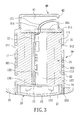
Fig. 3 is a sectional assembly view of a preferred embodiment of this invention; -
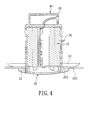
Fig. 4 is a schematic view illustrating a recessed lamp that is arranged on the ceiling in a preferred embodiment of this invention; -
Fig. 5 is a 3D assembly view of another preferred embodiment of this invention; -
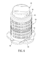
Fig. 6 is a 3D assembly view of a further embodiment of this invention; -
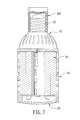
Fig. 7 is a schematic view illustrating the lamp according to this invention that is applied to a lamp bulb mount; and -
Fig. 8 is a schematic view illustrating the lamp according to this invention that is applied to an energy-saving lamp bulb. - Now, the present invention will be described more specifically with reference to the following embodiments. It is to be noted that the following descriptions of preferred embodiments of this invention are presented herein for purpose of illustration and description only; it is not intended to be exhaustive or to be limited to the precise form disclosed.
- Firstly, with reference to
figures 1 through 3 respectively shown as a 3D exploded view, a 3D assembly view, and an assembly sectional view, an inset lamp in a preferred embodiment of this invention comprises a light-source body 10, alamp cover 20, aninsulation cover 30, and anextension cover 40. - The light-
source body 10 further comprises aheat dissipation part 11, adrive circuit board 12, and aLED lamp board 13. - The
heat dissipation part 11 is metallic and is arranged lengthways in the form of a cylinder, and its center is formed with arectangular thru hole 111 that is formed axially with foursidewalls 1111, in which aconcave wedge slot 1112 is formed axially on the twosidewalls 1111 opposite to each other. Further, a plurality offins 112 is formed axially around the outer circumference ofheat sink part 11. A plurality ofannular grooves 113 are formed in a radial direction around the outer circumference ofheat dissipation part 11. Further, a plurality ofconvection vents 114 are axially formed in theheat dissipation part 11 around thethru hole 111 for heat convection and heat dissipation acceleration. - The
drive circuit board 12 may be lengthways mounted into thethru hole 111 ofheat dissipation part 11, and apower cord 121 is provided at an upper side and aninsertion slot 122 is formed at a lower side. - The
LED lamp board 13 is arranged transversally on a side below theheat dissipation part 11 and comprises asubstrate 131. TheLED lamp board 13 on the top side ofsubstrate 131 is provided with aplug 132 to connect to theinsertion slot 122 ofdrive circuit board 12. Besides, a plurality ofLEDs 133 are provided on the bottom side ofsubstrate 131 of theLED lamp board 13. - The
lamp cover 20 is arranged below theLED lamp board 13 and is formed into a mouth facing upwards; it is a round cover formed with an annulus wall and allows light transmission; ashoulder region 21 is formed around the outer circumference of root edge of thecover 20. Further, an opticscurved surface 22 is formed at the bottom side oflamp cover 20 so that thecover 20 may be replaced with aproper lamp cover 20 having the optics curvedsurface 22 upon an actual demand. - The
insulation cover 30 may wrap around theheat dissipation part 11 for fear of touch with the metallicheat dissipation part 11. In the embodiment, theinsulation cover 30 is further assembled with anupper insulation cover 31 and alower insulation cover 32. - The
upper insulation cover 31 is in the form of a cylinder and wraps around theheat dissipation part 11 from top to bottom. Further, the circumferential wall ofupper insulation cover 31 is formed in the shape of grille with a plurality ofheat dissipation vent 311. A plurality ofannular flanges 312 opposite to theannular grooves 113 ofheat dissipation part 11 are formed at the inner wall ofupper insulation cover 311 and may wedge to each other for clamping. Atop plate 313 is transversally arranged at the top ofinsulation cover 311 that is opposite to the top side ofheat dissipation part 11 to prevent the top side ofheat dissipation part 11 from being exposed for achievement of insulation. Anoutgoing line hole 314 is formed on thetop plate 313 the bottom side of which is formed with a plurality oflugs 315 to bring a plurality of air gaps between thetop plate 313 and the top ofheat dissipation 11 for heat dissipation. - The
lower insulation cover 32 is also in the form of a cylinder and wraps around the lower section ofheat dissipation part 11 from bottom to top. The circumferential wall oflower insulation cover 32 is also formed in the shape of grille with a plurality ofheat dissipation vents 321. A plurality ofannular flanges 32 opposite to theannular grooves 113 ofheat dissipation part 11 are formed at the inner wall oflower insulation cover 322 and may wedge to each other for clamping. A convexshift limit flange 323 is provided at theshoulder region 21 oflamp cover 20 that is opposite to the root edge of inner circumferential wall of thelower insulation cover 32 to prevent thelamp cover 20 from shifting. Further, anouter disk cover 33 spirally removable and replaceable is provided outwards and transversally in theinsulation cover 30 around the outer circumference of the lower part oflower insulation cover 32. Next, anelastic clamping flake 34 is provided at each of opposite two sides of theinsulation cover 30 around the outer circumferential wall oflower insulation cover 32 above theouter disk cover 33. Theelastic clamping flake 34 may be removable and may recover even if being deformed with an external force. A space substantially equal to the thickness of ceiling is formed between theelastic clamping flake 34 and theouter disk cover 33. Each of theelastic clamping flakes 34 is a metallic elastic flake one end of which is a fixed end fixed in the direction of tangent onto thelower insulation cover 32 and the other end of which is a free end, and the bottom of each of theelastic clamping flakes 34 is convergent from the fixed end towards the free end. - The
extension cover 40 is formed into a mouth facing downwards and with a round cover having an annular wall, and may be wedged onto the top ofupper insulation cover 31. Achamber 41 is provided in theextension cover 40 for members, such as rechargeable batteries (not shown). Here, the lamp according to this invention may be used for emergency. Anoutgoing line mount 42 is provided at one side of theextension cover 40 for apower cord 121 of thedrive circuit board 12 to connect to. - Again, with reference to
figures 1 and3 , when the lamp according to this invention is ready for assembly, firstly, a light-emittingbody 10 is assembled, thedrive circuit board 12 is placed in thethru hole 111 ofheat dissipation part 11, and two sides of thedrive circuit board 12 is wedged into thewedge slots 1112 ofheat dissipation part 11 for fixing. Then, theplug 132 ofLED lamp board 13 is plugged into theinsertion slot 122 ofdrive circuit board 12, theLED lamp board 13 is thus arranged on the bottom surface ofheat dissipation part 11, and the bottom sides ofLEDs 133 are made to touch theheat dissipation part 11. Then, thelamp cover 20 is placed in thelower insulation cover 32, thelower insulation cover 32 is made to wrap around the lower section ofheat dissipation part 11 from bottom to top, and thus thelamp cover 20 is made to exactly cover theLED lamp board 13. Next, theupper insulation cover 31 is made to wrap around the upper section ofheat dissipation part 11 from top to bottom and to wedge to thelower insulation cover 32. Next, theouter disk cover 33 is spirally fixed onto thelower insulation cover 32. Finally, thepower cord 121 ofdrive circuit board 12 is connected to theoutgoing line mount 42 of theextension cover 40 and theextension cover 40 is wedged onto the top ofupper insulation cover 31, thereby the assembly procedure being finished. - With reference to
figure 4 shown as a schematic view illustrating the lamp according to this invention arranged on the ceiling, when the lamp according to this invention is installed in aninset hole 201 of theceiling 200, the elastic clampingflake 34 of the lamp according to this invention is just bent inwards and then the lamp according to this invention is placed into theinset hole 201 of the ceiling from bottom to top. At this time, when the elastic clampingflake 34 bounces outwards, it works with theouter disk cover 33 to limit the shift ofceiling 200. Further, the area ofouter disk cover 33 is definitely wide to cover the differentlysized inset hole 201 of theceiling 200, thereby the installation being finished. - Contrarily, to remove the lamp according to this invention from the
inset hole 201 of theceiling 200, the lamp according to this invention is revolved in a reverse direction only towards the free end of elastic clampingflake 34 from the top down. Being convergent, the bottom of elastic clampingflake 34 led by theinset hole 201 is bent inwards by degree until the lamp according to this invention is fully removed from theinset hole 201 of theceiling 200, thereby the removal being finished. - With reference to
figure 5 shown as a 3D assembly view of another preferred embodiment of this invention, the elastic clampingflake 35 according to this invention is a metallic flake in the form of a rhombus, the middle region of which is lengthways fixed onto thelower insulation cover 32 and the left and right sides of which are formed into free ends. - With reference to
figure 6 shown as a 3D assembly view of a further preferred embodiment of this invention, anouter disk cover 36 is spirally fixed to the outer circumference of a lower part of thelower insulation cover 32 ofinsulation cover 30. Theouter disk cover 36 is in the form of a petal and thus the lamp according to this invention is diverse. - Next, with reference to
figures 6 and7 respectively shown as a 3D assembly view of a further preferred embodiment of this invention and as a schematic view illustrating the lamp according to this invention applied to a lamp bulb mount, the top of extension cover 40 according to this invention may be changed into auniversal spiral connector 43 for a lamp bulb mount so that the lamp according to this invention may be spirally fixed onto a generallamp bulb mount 300. Next, theouter disk cover 36 is removed so that the lamp according to this invention may herein be used as a lamp bulb. - Next, with reference to
figure 8 shown as a schematic view illustrating the lamp according to this invention applied to an energy-saving lamp bulb, in this embodiment, a light-source body 50 according to this invention is an energy-saving lamp bulb. The light-source body 50 is provided with a base 51 the exterior of which is formed withouter threads 511 so that the outer circumference of light-source body 50 may be spirally fixed onto the top of aninsulation cover 60 withinner threads 61. Further, anouter disk cover 62 is spirally fixed to the outer circumference of the lower part ofinsulation cover 60. - While the invention has been described in terms of what is presently considered to be the most practical and preferred embodiments, it is to be understood that the invention needs not be limited to the disclosed embodiment. On the contrary, it is intended to cover various modifications and similar arrangements included within the spirit and scope of the appended claims which are to be accorded with the broadest interpretation so as to encompass all such modifications and similar structures.
Claims (10)
- A combinational inset lamp exempt from a shielding cylinder, being possible to inset to an inset hole of the ceiling and comprising:a light-source body;a lamp cover allowing light transmission and being arranged below thelight-source body; andan insulation cover being in the form of a hollow cylinder, wrapping around the outer circumference of light-source body, and clamping the lamp cover, in which an outer disk cover removable and replaceable is provided outwards and transversally in the insulation cover around the outer circumference of the lower part of lower insulation cover, at least opposite two sides of the outer circumferential wall of insulation cover are respectively formed outwards with an elastic clamping flake that is capable of recovering even if being deformed with an external force, and a space substantially equal to the thickness of ceiling is formed between theelastic clamping flake and the outer disk cover.
- The combinational inset lamp exempt from the shielding cylinder according to claim 1, wherein the light-source body further comprises:a heat dissipation part that is metallic and is arranged lengthways in the form of a cylinder, the center of which is formed axially with a rectangularthru hole;a drive circuit board lengthways mounted into the thru hole of heat dissipation part to drive LEDs; anda LED lamp board that is arranged transversally on a side below the heat dissipation part and comprises a substrate connected to a circuit substrate,in which a plurality of LEDs are provided on the substrate.
- The combinational inset lamp exempt from the shielding cylinder according to claim 2, wherein the thru hole of heat dissipation part is rectangular and formed axially with four sidewalls two opposite sidewalls of which are formed axially with a concave wedge slot to wedge the two sides of the drive circuit board into the wedge slot.
- The combinational inset lamp exempt from the shielding cylinder according to claim 2, wherein the insulation cover is assembled with an upper insulation cover and a lower insulation cover, the upper insulation cover wraps around the upper section of heat dissipation part from top to bottom, a flange is provided around the outer circumference of lower section, the lower insulation cover wraps around the lower section of heat dissipation part from bottom to top, and a groove is arranged around the inner side of the circumference of lower section opposite to the flange of upper insulation cover.
- The combinational inset lamp exempt from the shielding cylinder according to claim 2, wherein a plurality of annular grooves are formed in a radial direction around the outer circumference of heat dissipation part and a plurality of annular flanges opposite to the annular grooves are formed at the inner wall of insulation cover for clamping.
- The combinational inset lamp exempt from the shielding cylinder according to claim 2, wherein a top plate is transversally arranged at the top of insulation cover that is opposite to the top side of heat dissipation part to prevent the top side of heat dissipation part from being exposed for achievement of insulation and an outgoing line hole is formed on the top plate the bottom side of which is formed with a plurality of lugs.
- The combinational inset lamp exempt from the shielding cylinder according to claim 1, wherein the lamp cover is formed into a mouth facing upwards, a round cover formed with an annulus wall, and allows light transmission, an optics curved surface is formed at the bottom side of lamp cover, a shoulder region is formed around the outer circumference of root edge of the cover, and a convex shift limit flange is provided at the shoulder region of lamp cover that is opposite to the root edge of inner circumferential wall of the insulation cover to resist the shoulder of lamp cover and thus prevent the lamp cover from shifting.
- The combinational inset lamp exempt from the shielding cylinder according to claim 1, wherein the lamp further comprises an extension cover wedged onto the top of upper insulation cover, and a chamber is provided in the extension cover.
- The combinational inset lamp exempt from the shielding cylinder according to claim 8, wherein one side of the extension cover is formed into a universal spiral connector for a lamp bulb mount so that the extension cover may be spirally fixed onto the general lamp bulb mount.
- The combinational inset lamp exempt from the shielding cylinder according to claim 1, wherein each of the elastic clamping flakes is a metallic elastic flake one end of which is a fixed end fixed in the direction of tangent onto the insulation cover and the other end of which is a free end, and the bottom of each of the elastic clamping flakes is convergent from the fixed end towards the free end.
Priority Applications (1)
| Application Number | Priority Date | Filing Date | Title |
|---|---|---|---|
| EP08165978A EP2175191A1 (en) | 2008-10-07 | 2008-10-07 | Combinational inset lamp exempt from a shielding cylinder |
Applications Claiming Priority (1)
| Application Number | Priority Date | Filing Date | Title |
|---|---|---|---|
| EP08165978A EP2175191A1 (en) | 2008-10-07 | 2008-10-07 | Combinational inset lamp exempt from a shielding cylinder |
Publications (1)
| Publication Number | Publication Date |
|---|---|
| EP2175191A1 true EP2175191A1 (en) | 2010-04-14 |
Family
ID=40343586
Family Applications (1)
| Application Number | Title | Priority Date | Filing Date |
|---|---|---|---|
| EP08165978A Withdrawn EP2175191A1 (en) | 2008-10-07 | 2008-10-07 | Combinational inset lamp exempt from a shielding cylinder |
Country Status (1)
| Country | Link |
|---|---|
| EP (1) | EP2175191A1 (en) |
Cited By (3)
| Publication number | Priority date | Publication date | Assignee | Title |
|---|---|---|---|---|
| CN104964220A (en) * | 2015-07-28 | 2015-10-07 | 江苏达伦电子股份有限公司 | LED ceiling lamp with two lamp covers |
| EP3242071A1 (en) * | 2012-10-05 | 2017-11-08 | Fischer Lighting ApS | Lighting device, insertion and receiving element |
| WO2022043646A1 (en) * | 2020-08-26 | 2022-03-03 | Birkby Derek Laycock | A ceiling downlight |
Citations (4)
| Publication number | Priority date | Publication date | Assignee | Title |
|---|---|---|---|---|
| US5567041A (en) * | 1995-08-14 | 1996-10-22 | Slocum; Karl | Self supporting recessed ceiling fixture |
| WO2006094346A1 (en) * | 2005-03-08 | 2006-09-14 | Grant Harold Amor | Led lighting apparatus in a plastic housing |
| US20070253202A1 (en) * | 2006-04-28 | 2007-11-01 | Chaun-Choung Technology Corp. | LED lamp and heat-dissipating structure thereof |
| EP1950491A1 (en) * | 2007-01-26 | 2008-07-30 | Piper Lux S.r.l. | LED spotlight |
-
2008
- 2008-10-07 EP EP08165978A patent/EP2175191A1/en not_active Withdrawn
Patent Citations (4)
| Publication number | Priority date | Publication date | Assignee | Title |
|---|---|---|---|---|
| US5567041A (en) * | 1995-08-14 | 1996-10-22 | Slocum; Karl | Self supporting recessed ceiling fixture |
| WO2006094346A1 (en) * | 2005-03-08 | 2006-09-14 | Grant Harold Amor | Led lighting apparatus in a plastic housing |
| US20070253202A1 (en) * | 2006-04-28 | 2007-11-01 | Chaun-Choung Technology Corp. | LED lamp and heat-dissipating structure thereof |
| EP1950491A1 (en) * | 2007-01-26 | 2008-07-30 | Piper Lux S.r.l. | LED spotlight |
Cited By (5)
| Publication number | Priority date | Publication date | Assignee | Title |
|---|---|---|---|---|
| EP3242071A1 (en) * | 2012-10-05 | 2017-11-08 | Fischer Lighting ApS | Lighting device, insertion and receiving element |
| CN104964220A (en) * | 2015-07-28 | 2015-10-07 | 江苏达伦电子股份有限公司 | LED ceiling lamp with two lamp covers |
| CN104964220B (en) * | 2015-07-28 | 2018-04-03 | 江苏达伦电子股份有限公司 | A kind of LED pendent lamps of double lampshade |
| WO2022043646A1 (en) * | 2020-08-26 | 2022-03-03 | Birkby Derek Laycock | A ceiling downlight |
| GB2600908A (en) * | 2020-08-26 | 2022-05-18 | Laycock Birkby Derek | A ceiling downlight |
Similar Documents
| Publication | Publication Date | Title |
|---|---|---|
| US7832909B2 (en) | Combinational inset lamp exempt from a shielding cylinder | |
| EP3047200B1 (en) | Solid-state lighting devices and systems | |
| EP2378184B1 (en) | Lamp assembly | |
| US8287160B2 (en) | LED light assembly | |
| EP2784383B1 (en) | Heat dissipation facilitating led lamp | |
| EP2444724B1 (en) | LED bulb | |
| JP5284522B1 (en) | Optical semiconductor lighting device | |
| EP2378185A2 (en) | Lamp assembly | |
| WO2012126749A1 (en) | Downlight with illumination angle adjustable polydirectionally | |
| US20080253116A1 (en) | Lamp Structure | |
| US8608352B2 (en) | Illuminating device | |
| KR20140100382A (en) | Heat sink module and omnidirectional led lamp holder assembly using same | |
| JP6074515B2 (en) | Heat dissipation device for lighting | |
| JP3182121U (en) | LED lighting device | |
| EP2175191A1 (en) | Combinational inset lamp exempt from a shielding cylinder | |
| AU2008101029A4 (en) | Combinational inset lamp exempt from a shielding cylinder | |
| JP3166364U (en) | Light bulb type LED lighting device and heat dissipation structure thereof | |
| WO2014172610A2 (en) | Omni-directional led lamp | |
| EP2899450B1 (en) | LED lighting apparatus | |
| KR101602304B1 (en) | Heat sink apparatus | |
| CN202001904U (en) | Light-emitting diode (LED) down lamp | |
| CN111578244B (en) | Heat dissipation shell and lamp | |
| CN101639163B (en) | Lamp | |
| CN104214573B (en) | Straight tube led lamp | |
| CA2342306C (en) | Heat conducting multi position reflector neck assembly |
Legal Events
| Date | Code | Title | Description |
|---|---|---|---|
| PUAI | Public reference made under article 153(3) epc to a published international application that has entered the european phase |
Free format text: ORIGINAL CODE: 0009012 |
|
| AK | Designated contracting states |
Kind code of ref document: A1 Designated state(s): AT BE BG CH CY CZ DE DK EE ES FI FR GB GR HR HU IE IS IT LI LT LU LV MC MT NL NO PL PT RO SE SI SK TR |
|
| AX | Request for extension of the european patent |
Extension state: AL BA MK RS |
|
| AKY | No designation fees paid | ||
| STAA | Information on the status of an ep patent application or granted ep patent |
Free format text: STATUS: THE APPLICATION IS DEEMED TO BE WITHDRAWN |
|
| 18D | Application deemed to be withdrawn |
Effective date: 20101015 |
|
| REG | Reference to a national code |
Ref country code: DE Ref legal event code: R108 Effective date: 20110419 |