EP2168419A1 - Agricultural harvester - Google Patents
Agricultural harvester Download PDFInfo
- Publication number
- EP2168419A1 EP2168419A1 EP09164080A EP09164080A EP2168419A1 EP 2168419 A1 EP2168419 A1 EP 2168419A1 EP 09164080 A EP09164080 A EP 09164080A EP 09164080 A EP09164080 A EP 09164080A EP 2168419 A1 EP2168419 A1 EP 2168419A1
- Authority
- EP
- European Patent Office
- Prior art keywords
- harvester
- self
- propelled
- analysis
- fractions
- Prior art date
- Legal status (The legal status is an assumption and is not a legal conclusion. Google has not performed a legal analysis and makes no representation as to the accuracy of the status listed.)
- Granted
Links
Images


Classifications
-
- A—HUMAN NECESSITIES
- A01—AGRICULTURE; FORESTRY; ANIMAL HUSBANDRY; HUNTING; TRAPPING; FISHING
- A01D—HARVESTING; MOWING
- A01D41/00—Combines, i.e. harvesters or mowers combined with threshing devices
- A01D41/12—Details of combines
- A01D41/127—Control or measuring arrangements specially adapted for combines
- A01D41/1277—Control or measuring arrangements specially adapted for combines for measuring grain quality
-
- A—HUMAN NECESSITIES
- A01—AGRICULTURE; FORESTRY; ANIMAL HUSBANDRY; HUNTING; TRAPPING; FISHING
- A01D—HARVESTING; MOWING
- A01D41/00—Combines, i.e. harvesters or mowers combined with threshing devices
- A01D41/12—Details of combines
- A01D41/1208—Tanks for grain or chaff
-
- A—HUMAN NECESSITIES
- A01—AGRICULTURE; FORESTRY; ANIMAL HUSBANDRY; HUNTING; TRAPPING; FISHING
- A01D—HARVESTING; MOWING
- A01D41/00—Combines, i.e. harvesters or mowers combined with threshing devices
- A01D41/12—Details of combines
- A01D41/127—Control or measuring arrangements specially adapted for combines
- A01D41/1275—Control or measuring arrangements specially adapted for combines for the level of grain in grain tanks
Definitions
- the invention relates to an agricultural harvesting machine, in particular a combine harvester, according to the preamble of claim 1,
- a combine harvester which has a grain tank which is subdivided into fractions, with the corn kernel storing the corn kernels in one fraction and the so-called spindles in the further fraction of the grain tank.
- the division of the emerging from the threshing and separating device consisting of corn grains and spindles Nutzmalerialstromes is made in a mechanically operating Separieran ever.
- a litter roller accelerates the flow of useful material. The accelerated stream of useful material passes into a flight phase on leaving the littering roll, with the corn kernels and the spindles moving on different trajectories, depending on their specific properties.
- the useful material stream at the end of the flight phase is separated into a useful material stream consisting predominantly of corn kernels and a predominantly spindles. Both streams of useful material are then fed via conveyors to the respective fractions of the grain tank.
- Such an embodiment of a separating device has the particular disadvantage that the fractionation is gravity-dependent and the free-flying good components of a variety of external influences, such as the trajectory changing friction effects between the Gut confuseer subject, ultimately affecting the accuracy of fractionation strong.
- the self-propelled harvester in particular a combine harvester, with a harvesting header for harvesting stalks, working organs for ginning the stalk and separating and cleaning the stalk separated from the crop, forming a Nutzmaterialsstrom fruit stands
- at least one conveyor for transporting the Nutzmaterialstromes over a Gutstromteiler in a storage device which is subdivided into at least two fractions of the at least one conveyor of the agricultural harvesting machine, is assigned an analyzer device which permanently detects specific parameters of the useful material flow and, depending on the analysis result, the crop flow divider feeds the useful material flow to one of the at least two fractions of the storage device ensures that with high fractionation accuracy a Nutzmaterialstrom is divided into different good qualities having Operanutzmatertaiströme.
- a crop with very homogeneous, almost identical good properties can be provided, which on the producer side also leads to higher yields because of the more homogeneous quality.
- the analysis device of the at least one conveyor is assigned as a bypass in such a way that permanently an analysis material flow of the conveyor passing through the useful material flow is deflected into the analysis device and is fed back to the Nutzmaterialsstrom after its analysis.
- an advantageous embodiment of the invention associates a sensor head, wherein a high-quality determination of the contents is achieved when the sensor head comprises a NIR sensor which has proven itself many times over.
- a particularly efficiently operating and cost-effective structure having analysis device is created when the sensor head is designed as a standard deliverable reflection measuring head and / or transmission measuring head. While the former analyzes light waves reflected from the analyte material stream, the latter analyzes the lightwaves passing through the analyte material stream.
- the transmission measuring head and the reflection measuring head By alternatively or jointly integrating the transmission measuring head and the reflection measuring head into the analysis device, it is additionally ensured that the more suitable measuring method can be used in each case, depending on the characteristics of goodness and the ambient conditions.
- a structurally particularly simple structure results for the change between alternative or common arrangement of the reflection measuring head and the transmission measuring head when the transmission measuring head is arranged detachably on the analysis device.
- the sensor head is / are associated with a light barrier and / or one or more temperature sensors.
- the Gutstromteiler comprises a pivotable switch which releases in dependence on the control signals generated by the control and regulating device access to the respective fraction of the storage device.
- the switch is pivotable by means of lifting cylinder, the switch in its first end position closes the one access and the further access releases while it closes the other access in a second end position and releases the other access.
- the low-interference transfer of the sectionnutzmaterialströme from the at least one conveyor via the Gutstromteiler to the respective fraction of the storage device is also improved by the fact that each access of the flow divider to the respective fraction a screw conveyor is assigned, which promotes the Nutzmaterialstrom in the respective fraction of the storage device.
- each screw conveyor rigidly or pivotally passes through the respective fraction of the storage device.
- a favorable arrangement of the screw conveyors and a large storage volume of the fractions result in an advantageous embodiment of the invention when the storage device is divided transversely to the longitudinal direction of the harvester into fractions.
- quality characteristics can be edited in the control and regulating device for defining the quality of the useful material streams storable in the fractions of the storage device.
- the filling level of the fractions of the storage device is monitored by means of sensing devices, the sensing devices preferably being in the form of a camera are.
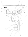
- FIG. 1 shows an executed as a combine harvester 2 agricultural harvester 1, in known per se and therefore not executed in detail, the combine harvester 2 front cereal cutter 3 assigned, which harvests the crop grown 4 and feeds the threshing members 6 of the combine harvester 2 via a Schragjan Republic 5.
- a product stream 7 predominantly consisting of grains is fed via a preparation tray 8 to a cleaning device 9.
- Another crop stream 10 occurs in the rear region of the threshing 6 from these and reaches a running in the illustrated embodiment as Horden presentler 11 separator 12.
- a further, consisting mainly of grains material stream 13 is deposited, via a return bottom 14 and the preparation tray 8 is also supplied to the cleaning device 9.
- the cleaning device 9 at least one cleaned, consisting of grains useful material flow 15 is deposited, which is supplied via at least one, designed as an elevator 16 conveyor 17 of a designed as a grain tank 18 storage device 19.
- the storage device 19 is subdivided into a first fraction 21 and at least one further fraction 22 by means of a dividing wall 20 which is made of solid or flexible material and is arranged transversely to the direction of travel FR. It is within the scope of the invention that the storage device 19 is divided into a plurality of fractions 21, 22 is divided, depending on how many quality levels of the useful material flow 15 is to be separated in the memory device 19.
- the top end of the at least one conveyor 17 in the region of the storage device 19 opens into a material flow divider 23, which separates the useful material flow 15 into partial payload streams 24.
- the Gutstromteiler 23 memory device side for each of the fractions 21, 22 of the grain tank 18 each associated with a screw conveyor 25, either rigidly or pivotally movable into the respective fraction 21, 22 of the grain tank 18 protrudes.
- the at least one conveying device 17 is assigned an analysis device 26 as a bypass 27 for the detection of specific parameters X of the useful material flow 15 passing through the conveying device 17.
- the specific parameters X detected by the analysis device 26 are transmitted to a control and regulating device 28 by line or wireless transmission.
- So-called quality characteristics 29 are stored in the control and regulating device 28, which define the quality of the partial useful material flow 24 to be stored there for each of the fractions 21, 22 of the storage device 19.
- the stored quality characteristics 29 are editable.
- the control and regulating device 28 Depending on the quality criteria of the sub-user material streams 24 assigned to each fraction 21, 22 of the storage device 19, the control and regulating device 28 generates control signals Y, which the goods flow divider 23 so to control that in a manner to be described in more detail the promotion of a Clausnutzmaterialstroms 24 in the corresponding fraction 21, 22 of the Speicheinnchiung 19 is effected.
- FIG. 2 1 shows a schematic top view of the storage device 19 embodied as a grain tank 18.
- the at least one conveyor 17 designed as an elevator 16 passes through the wall 30 of the storage device 19 and enters the good-flow divider 23 assigned to it on the top takes a pivotable about a vertical axis 31, executed in the simplest case as a flat sheet switch 32, which can be moved via a driven by lifting cylinder 33 pivot mechanism 34 in two end positions 35, 36.
- the switch 32 closes the access 37 to the feed screw 25 passing through the first fraction 21, while the further access 38 into the second fraction 22 of the storage device 19 is released.
- each access 37, 38 a transfer trough 39 is formed outside the Gutstromteilers 23, in which the screw conveyor 25 of the respective fraction 21, 22 engages, and the respective Operanutzmaterialstrom 24 from the range of Gutstromteilers 23 in the respective fraction 21, 22 of the storage device 19 carry away, wherein each of the screw conveyors 25, as already described, can be positioned rigidly or pivotably in the respective fraction 21, 22 of the storage device 19.
- Each fraction 21, 22 of the storage device 19 is assigned in its lower-side region in each case a screw conveyor 40 for conveying the Operanutzmaterialströme 24 from the respective fraction 21, 22, the energiedes the Operanutzmaterialströme 24 passed to a Questionladeschnecke 41, by means of which the Partnutzmaterialströme 24 on a transfer vehicle be encouraged.
- FIG. 3 shows a schematic detail view of the analysis device 26 according to the invention.
- the analyzer 26 is the outside of at least one designed as an elevator 16 conveyor 17 associated with the partition 42 between the analyzer 26 and the conveyor 17 seen in Guthneetti G an upper passage opening 43 and a lower Gut maltrittsö réelle 44th having. About the upper Gut maltrittsö réelle 43 managed a portion of the Nutzmaterialstromes 15 as so-called analysis material flow 45 in the analyzer 26, happens in this gravity due to a sensor head 46 and 26 at the bottom end of the analyzer 26 via suitable conveyor 47 via the lower Gut miceriesöffrnung 44 back into the conveyor 17th recycled.
- the sensor head 46 is formed as a so-called NIR sensor (near-infrared sensor) 48, which is able to detect specific parameters X of the analysis material flow 45 and thus the associated Nutzmatenalstromes 15.
- the sensor head 46 is designed as a known per se and therefore not described in detail reflection measuring head 49 whose light source illuminates the analysis material 45 and its reflection measuring device analyzes the reflected light waves and determined from this analysis specific parameters X of the analysis material flow 45 and thus the Nutzmaterialsstromes 15 wherein the specific parameters X may be one or more ingredients, such as protein content or the like.
- the sensor head 46 can also according to the left illustration in FIG. 3 be designed as a transmission measuring head 50.
- the analysis material stream 45 is transilluminated by the light source of the transmission probe 50, the specific parameters X are determined by analyzing the light rays passing through the analysis material stream 45. Due to the fact that the determination of the ingredient by means of the described NIR sensors 48 only provides useful results when a certain minimum amount of material to be detected passes through the sensor head 46 and during the measurement optimal temperatures prevail, the sensor head 46 depending on the desired measurement accuracy a light barrier 51st for good quantity detection and / or temperature sensors 52 for determining the temperature of the analysis material flow 45 and the outside temperature associated.
- the analysis device 26 may also be designed such that it comprises both a reflection measuring head 49 and a transmission measuring head 50, in which case the transmission measuring head 50 is associated with the reflection measuring head 49 as a bypass, so that it depends on the characteristics of goodness and ambient conditions in each of the better with the respective conditions coping sensor head 46 can be used.
- the analysis device 26 communicates with the control and regulating device 28 arranged in the analysis device 26 or at any location in the agricultural harvesting machine 1.
- the control and regulating device 28 may be designed such that it first generates the good throughput signals Q generated by the light barrier 51 temperature signals T generated by the temperature sensors 52 and activates the sensor head or heads 46 only if the material flow rate and / or the temperature are in a range that can be expected useful measurement results for the specific parameter X, Next are in the spreader and crizeinrichfung 28th as described above, editable quality characteristics 29 are deposited, which define the quality parameters of the fractions 21, 22 of the storage device 19 to be supplied Operanutzmaterialströme 24. Depending on the quality characteristics 29, the control and evaluation device 28 finally generates a control signal Y.
- the degree of filling of the fractions 21, 22 will differ from one another.
- the filling level of each fraction 21, 22 is monitored by means of a suitable sensing device 53, preferably a camera 54.
Landscapes
- Life Sciences & Earth Sciences (AREA)
- Environmental Sciences (AREA)
- Threshing Machine Elements (AREA)
- Management, Administration, Business Operations System, And Electronic Commerce (AREA)
Abstract
Description
Die Erfindung betrifft eine landwirtschaftliche Erntemaschine, insbesondere Mähdrescher, nach dem Oberbegriff des Anspruchs 1,The invention relates to an agricultural harvesting machine, in particular a combine harvester, according to the preamble of claim 1,
Aus der
Diesen Nachteil überwindend, schlägt die
Es ist deshalb Aufgabe der Erfindung die beschriebenen Nachteile des Standes der Technik zu vermeiden und insbesondere eine Separiereinnchtung für landwirtschaftliche Erntemaschinen vorzuschlagen, die mit hoher Fraktioniergenauigkeit einen Nutzmaterialstrom in unterschiedliche Gutqualitäten aufweisende Teilnutzmaterialströme aufteilen kann.It is therefore an object of the invention to avoid the disadvantages of the prior art described and in particular to propose a SeparariEnchtung for agricultural harvesters, which can divide a Nutzmaterialstrom with different grades having Teilnutzmaterialströme with high Fraktioniergenauigkeit.
Diese Aufgabe wird erfindungsgemäß durch die kennzeichnenden Merkmale des Anspruchs 1 gelöst.This object is achieved by the characterizing features of claim 1.
Indem der selbstfahrenden Erntemaschine, insbesondere einem Mähdrescher, mit einem Erntevorsatz zum Ernten von Halmgut, Arbeitsorganen zur Entkörnung des Halmgutes und zur Trennung und Reinigung der aus dem Halmgut separierten, einen Nutzmaterialstrom bildenden Fruchtstände, zumindest einer Fördereinrichtung für den Transport des Nutzmaterialstromes über einen Gutstromteiler in eine zumindest in zwei Fraktionen unterteilte Speichereinrichtung der zumindest einen Fördereinrichtung der landwirtschaftlichen Erntemaschine, eine permanent spezifische Parameter des Nutzmaterialstroms detektierende Analyseeinrichtung zugeordnet ist und in Abhängigkeit von dem Analyseergebnis der Gutstromteiler den Nutzmaterialstrom einer der zumindest zwei Fraktionen der Speichereinrichtung zuführt wird sichergestellt, dass mit hoher Fraktioniergenauigkeit ein Nutzmaterialstrom in unterschiedliche Gutqualitäten aufweisende Teilnutzmatertaiströme aufgeteilt wird. Auf diese Weise kann in Abhängigkeit von Kundenwünschen ein Erntegut mit sehr homogenen, nahezu identischen Guteigenschaften bereitgestellt werden, was auf Erzeugerseite wegen der homogeneren Qualität auch zu höheren Erlösen führt.By the self-propelled harvester, in particular a combine harvester, with a harvesting header for harvesting stalks, working organs for ginning the stalk and separating and cleaning the stalk separated from the crop, forming a Nutzmaterialsstrom fruit stands, at least one conveyor for transporting the Nutzmaterialstromes over a Gutstromteiler in a storage device, which is subdivided into at least two fractions of the at least one conveyor of the agricultural harvesting machine, is assigned an analyzer device which permanently detects specific parameters of the useful material flow and, depending on the analysis result, the crop flow divider feeds the useful material flow to one of the at least two fractions of the storage device ensures that with high fractionation accuracy a Nutzmaterialstrom is divided into different good qualities having Teilnutzmatertaiströme. In this way, depending on customer requirements, a crop with very homogeneous, almost identical good properties can be provided, which on the producer side also leads to higher yields because of the more homogeneous quality.
In einer vorteilhaften Ausgestaltung der Erfindung ist die Analyseeinrichtung der zumindest einen Fördereinrichtung als Bypass in der Weise zugeordnet, dass permanent ein Analysematerialstrom des die Fördereinrichtung durchlaufenden Nutzmaterialstromes in die Analyseeinrichtung umgelenkt wird und nach dessen Analyse dem Nutzmaterialstrom wieder zugeführt wird. Dies hat insbesondere den Vorteil, dass einerseits die Qualität des Nutzmaterialstroms kontinuierlich überwacht wird und dass andererseits zur Ableitung des zu detektierenden Analysematerialstroms nur geringer technischer Aufwand betrieben werden muss.In an advantageous embodiment of the invention, the analysis device of the at least one conveyor is assigned as a bypass in such a way that permanently an analysis material flow of the conveyor passing through the useful material flow is deflected into the analysis device and is fed back to the Nutzmaterialsstrom after its analysis. This has the particular advantage that, on the one hand, the quality of the stream of useful material is continuously monitored and, on the other hand, only minor technical effort has to be made to derive the analysis material stream to be detected.
Damit die Analyseeinrichtung spezifische Parameter des Analysematerialstromes unmittelbar detektieren kann ist ihr in vorteilhaften Weiterbildung der Erfindung ein Sensorkopf zugeordnet, wobei eine qualitativ hochwertige Inhaltsstoffbestimmung dann erreicht wird, wenn der Sensorkopf einen vielfach technisch bewährten NIR-Sensor umfasst.In order that the analysis device can directly detect specific parameters of the analysis material flow, an advantageous embodiment of the invention associates a sensor head, wherein a high-quality determination of the contents is achieved when the sensor head comprises a NIR sensor which has proven itself many times over.
Eine besonders effizient arbeitende und eine kostengünstig Struktur aufweisende Analyseeinrichtung wird dann geschaffen, wenn der Sensorkopf als serienmäßig lieferbarer Reflexionsmesskopf und/oder Transmissionsmesskopf ausgeführt ist. Während ersterer von dem Analysematerialstrom reflektierte Lichtwellen analysiert, analysiert letzterer die den Analysematerialstrom durchsetzenden Lichtwellen. Indem der Transmissionsmesskopf und der Reflexionsmesskopf alternativ oder gemeinsam in die Analyseeinrichtung integrierbar sind, wird zudem sichergestellt, dass in Abhängigkeit von den Guteigenschaften und den Umgebungsbedingungen jeweils das besser geeignete Messverfahren eingesetzt werden kann.A particularly efficiently operating and cost-effective structure having analysis device is created when the sensor head is designed as a standard deliverable reflection measuring head and / or transmission measuring head. While the former analyzes light waves reflected from the analyte material stream, the latter analyzes the lightwaves passing through the analyte material stream. By alternatively or jointly integrating the transmission measuring head and the reflection measuring head into the analysis device, it is additionally ensured that the more suitable measuring method can be used in each case, depending on the characteristics of goodness and the ambient conditions.
Eine konstruktiv besonders einfache Struktur ergibt sich für den Wechsel zwischen alternativer oder gemeinsamer Anordnung von Reflexionsmesskopf und Transmissionsmesskopf dann, wenn der Transmissionsmesskopf demontierbar an der Analyseeinrichtung angeordnet ist.A structurally particularly simple structure results for the change between alternative or common arrangement of the reflection measuring head and the transmission measuring head when the transmission measuring head is arranged detachably on the analysis device.
Damit die von der Analyseeinrichtung ermittelten spezifischen Parameter eine hohe Genauigkeit aufweisen, sind Mindestdurchsätze und bestimmte Temperaturbereiche während des Analyseprozesses erforderlich. Um optimale Messbedingungen zu gewährleisten, ist deshalb in einer vorteilhaften Ausgestaltung der Erfindung vorgesehen, dass dem Sensorkopf eine Lichtschranke und/oder ein oder mehrere Temperatursensoren zugeordnet ist/sind.In order for the specific parameters determined by the analyzer to have high accuracy, minimum throughputs and certain temperature ranges are required during the analysis process. In order to ensure optimum measuring conditions, it is therefore provided in an advantageous embodiment of the invention that the sensor head is / are associated with a light barrier and / or one or more temperature sensors.
Eine effiziente und schnelle Umsetzung der von der Analyseeinrichtung detektierten spezifischen Parameter in eine gezielte Übergabe des jeweiligen Teilfiutzniaierialstroms in die jeweilige Fraktion der Speichereinrichtung ergibt sich dann, wenn die Analyseeinrichtung mit einer Steuer- und Regeleinrichtung kommuniziert, die in Abhängigkeit von den ermittelten spezifischen Parametern des Nutzmaterialstromes den Gutstromteiler zur Förderung des Nutzmaterialstromes in eine der zumindest zwei Fraktionen der Speichereinrichtung ansteuert.An efficient and rapid implementation of the detected by the analyzer specific parameters in a targeted transfer of the respective Teilfiutzniaierialstroms in the respective fraction of the storage device is obtained when the analysis device communicates with a control and regulating device, which depends on the determined specific parameters of the Nutzmaterialstromes controls the Gutstromteiler to promote the Nutzmaterialstromes in one of the at least two fractions of the memory device.
Eine konstruktive einfache Struktur des Gutstromteilers ergibt sich in einer vorteilhaften Ausgestaltung der Erfindung, indem der Gutstromteiler eine schwenkbare Weiche umfasst die in Abhängigkeit von den von der Steuer- und Regeleinrichtung generierten Stellsignalen den Zugang zu der jeweiligen Fraktion der Speichereinrichtung freigibt.A constructive simple structure of the Gutstromteilers results in an advantageous embodiment of the invention by the Gutstromteiler comprises a pivotable switch which releases in dependence on the control signals generated by the control and regulating device access to the respective fraction of the storage device.
In einer vorteilhaften Weiterbildung der Erfindung ist die Weiche mittels Hubzylinder verschwenkbar, wobei die Weiche in ihrer ersten Endposition den einen Zugang verschließt und den weiteren Zugang freigibt während sie in einer zweiten Endposition den weiteren Zugang verschließt und den anderen Zugang freigibt. Dies hat insbesondere den Vorteil, dass mittels einer einzigen Weiche die Umlenkung der Teilnutzmaterialströme bewirkt werden kann und die Weiche zugleich in dem fließenden Gutstrom bewegbar ist, ohne dass Unterbrechungen im Gutfluss auftreten.In an advantageous embodiment of the invention, the switch is pivotable by means of lifting cylinder, the switch in its first end position closes the one access and the further access releases while it closes the other access in a second end position and releases the other access. This has the particular advantage that the deflection of the Teilnutzmaterialströme can be effected by means of a single turnout and the switch is also movable in the flowing stream of goods at the same time without interruptions occur in the crop flow.
Die störungsarme Übergabe der Teilnutzmaterialströme von der zumindest einen Fördereinrichtung über den Gutstromteiler an die jeweilige Fraktion der Speichereinrichtung wird auch dadurch noch verbessert, dass jedem Zugang des Gütstromteilers zu der jeweiligen Fraktion eine Förderschnecke zugeordnet ist, die den Nutzmaterialstrom in die jeweilige Fraktion der Speichereinrichtung fördert.The low-interference transfer of the Teilnutzmaterialströme from the at least one conveyor via the Gutstromteiler to the respective fraction of the storage device is also improved by the fact that each access of the flow divider to the respective fraction a screw conveyor is assigned, which promotes the Nutzmaterialstrom in the respective fraction of the storage device.
Um entweder eine optimale Befüllung jeder Fraktion der Speichereinrichtung bei höheren oder reduzierten Fertigungskosten sicherzustellen, ist in einer weiteren vorteilhaften Ausgestaltung der Erfindung vorgesehen, dass jede Förderschnecke starr oder verschwenkbar die jeweilige Fraktion der Speichereinrichtung durchsetzt.In order to ensure either optimal filling of each fraction of the storage device at higher or reduced production costs, it is provided in a further advantageous embodiment of the invention that each screw conveyor rigidly or pivotally passes through the respective fraction of the storage device.
Eine günstige Anordnung der Förderschnecken sowie ein großes Speichervolumen der Fraktionen ergeben sich in einer vorteilhaften Ausgestaltung der Erfindung dann, wenn die Speichereinrichtung quer zur Längsrichtung der Erntemaschine in Fraktionen unterteilt ist.A favorable arrangement of the screw conveyors and a large storage volume of the fractions result in an advantageous embodiment of the invention when the storage device is divided transversely to the longitudinal direction of the harvester into fractions.
In einer weiteren vorteilhaften Ausgestaltung der Erfindung sind in der Steuer- und Regeleinrichtung zur Definition der Qualität der in den Fraktionen der Speichereinrichtung speicherbaren Nutzmaterialströme Qualitätskennlinien editierbar hinterlegt. Dies hat insbesondere den Vorteil, dass kundenspezifisch spezielle Qualitätskriterien definierbar sind, die dann mittels der Steuer- und Regeleinrichtung auch sehr präzise eingehalten werden können.In a further advantageous embodiment of the invention, quality characteristics can be edited in the control and regulating device for defining the quality of the useful material streams storable in the fractions of the storage device. This has the particular advantage that customer-specific special quality criteria can be defined, which can then also be met very precisely by means of the control and regulating device.
Damit der Betreiber der landwirtschaftlichen Erntemaschine von einer anstrengenden und ermüdenden Überwachung der Befüllgrade der verschiedenen Fraktionen der Speichereinrichtung entlastet wird, ist in einer vorteilhaften Ausgestaltung der Erfindung vorgesehen, dass der Befüllgrad der Fraktionen der Speichereinrichtung mittels Sensiereinrichtungen überwacht wird, wobei die Sensierienrichtungen vorzugsweise als Kamera ausgebildet sind.So that the operator of the agricultural harvesting machine is relieved of a strenuous and tedious monitoring of the filling levels of the various fractions of the storage device, in an advantageous embodiment of the invention it is provided that the filling level of the fractions of the storage device is monitored by means of sensing devices, the sensing devices preferably being in the form of a camera are.
Weitere vorteilhafte Ausgestaltungen sind Gegenstand weiterer Unteransprüche und werden nachfolgend an Hand in mehreren Figuren dargestellter Ausfuhrurtgsbeispiefe beschrieben.
Es zeigen:
- Figur 1
- eine als Mähdrescher ausgeführte landwirtschaftliche Erntemaschine mit erfindungsgemäßer Analyseeinrichtung
- Figur 2
- eine Detailansicht der in Fraktionen unterteilen Speichereinrichtung nach
Figur 1 - Figur 3
- eine Detailansicht der Analyseeinrichtung nach
Figur 1
Show it:
- FIG. 1
- an agricultural harvester designed as a combine with an analysis device according to the invention
- FIG. 2
- a detailed view of the divided into fractions storage device according to
FIG. 1 - FIG. 3
- a detailed view of the analysis device according to
FIG. 1
In erfindungsgemäßer Weise ist die Speichereinrichtung 19 mittels einer aus festem oder flexiblem Material bestehenden und quer zur Fahrtrichtung FR angeordneten Trennwand 20 in eine erste Fraktion 21 und zumindest eine weitere Fraktion 22 unterteilt. Es liegt im Rahmen der Erfindung, dass die Speichereinrichtung 19 in eine Vielzahl von Fraktionen 21, 22 unterteilt ist, je nachdem in wie viele Qualitätsstufen der Nutzmaterialstrom 15 in der Speichereinrichtung 19 separiert werden soll. In noch näher zu beschreibender Weise mündet das obenseitige Ende der zumindest einen Fördereinrichtung 17 im Bereich der Speichereinrichtung 19 in einen Gutstromteiler 23, der den Nutzmaterialstrom 15 in Teilnutzmaterialströme 24 separiert. Zur Förderung der Teilnutzmaterialströme 24 in die jeweilige Fraktion 21, 22 der Speichereinrichtung 19 sind dem Gutstromteiler 23 speichereinrichtungsseitig für jede der Fraktionen 21, 22 des Korntanks 18 jeweils eine Förderschnecke 25 zugeordnet, die entweder starr oder schwenkbeweglich in die jeweilige Fraktion 21, 22 des Korntanks 18 hineinragt. Zugleich ist der wenigstens einen Fördereinrichtung 17 eine Analyseeinrichtung 26 als Bypass 27 zur Detektion spezifischer Parameter X des die Fördereinrichtung 17 durchlaufenden Nutzmaterialstromes 15 zugeordnet. In noch näher zu beschreibender Weise werden die von der Analyseeinrichtung 26 detektierten spezifischen Parameter X an eine Steuer- und Regeleinrichtung 28 leitungsbasiert oder drahtlos übermittelt. In der Steuer- und Regeleinrichtung 28 sind sogenannte Qualitätskennlinien 29 hinterlegt, die für jede der Fraktionen 21, 22 der Speichereinrichtung 19 die Qualität des dort zu speichernden Teilnutzmaterialstromes 24 definieren. Damit die Qualitätskriterien in Abhängigkeit von Kundenwünschen geändert werden können, sind die hinterlegten Qualitätskennlinien 29 editierbar, In Abhängigkeit von den jeder Fraktion 21, 22 der Speichereinrichtung 19 zugeordneten Qualitätskriterien der Teilnutzmaterialströme 24 generiert die Steuer- und Regeleinrichtung 28 Stellsignale Y, die den Gutstromteiler 23 so ansteuern, dass in noch näher zu beschreibender Weise die Förderung eines Teilnutzmaterialstroms 24 in die entsprechende Fraktion 21, 22 der Speichereinnchiung 19 bewirkt wird.In accordance with the invention, the
Jeder Fraktion 21, 22 der Speichereinrichtung 19 ist in ihrem untenseitigen Bereich jeweils eine Förderschnecke 40 zur Abförderung der Teilnutzmaterialströme 24 aus der jeweiligen Fraktion 21, 22 zugeordnet, die einendes die Teilnutzmaterialströme 24 an eine Überladeschnecke 41 übergeben, mittels derer die Teilnutzmaterialströme 24 auf ein Überladefahrzeug gefördert werden.Each
In einer bevorzugten Ausgestaitungsvariante ist der Sensorkopf 46 als sogenannter NIR-Sensor (Nah-Infrarot-Sensor) 48 ausgebildet, der in der Lage ist, spezifische Parameter X des Analysematerialstromes 45 und damit des zugehörigen Nutzmatenalstromes 15 zu detektieren. In einer ersten Ausgestaltung ist der Sensorkopf 46 als an sich bekannter und deshalb nicht näher beschriebener Reflexionsmesskopf 49 ausgestaltet, dessen Lichtquelle den Analysematerialstrom 45 anstrahlt und dessen Reflexionsmesseinrichtung die reflektierten Lichtwellen analysiert und aus dieser Analyse spezifische Parameter X des Analysematerialstroms 45 und damit des Nutzmaterialstromes 15 ermittelt, wobei die spezifischen Parameter X ein oder mehrere Inhaltstoffe, wie Proteingehalt oder dergleichen, sein können. Der Sensorkopf 46 kann aber auch gemäß der linken Darstellung in
In einer weiteren Ausgestaltung der Erfindung kann die Analyseeinrichtung 26 auch so beschaffen sein, dass sie sowohl einen Reflexionsmesskopf 49 als auch einen Transmissionsmesskopf 50 umfasst, wobei in diesem Fall der Transmissionsmesskopf 50 als Bypass dem Reflexionsmesskopf 49 demontierbar zugeordnet ist, sodass in Abhängigkeit von den Guteigenschaften und Umgebungsbedingungen jeweils der besser mit den jeweiligen Bedingungen zurechtkommende Sensorkopf 46 einsetzbar ist.In a further embodiment of the invention, the
Die Analyseeinrichtung 26 kommuniziert mit der in der Analyseeinrichtung 26 oder an beliebiger Stelle in der landwirtschaftlichen Erntemaschine 1 angeordneten Steuer- und Regeleinrichtung 28. Die Steuer- und Regeleinrichtung 28 kann so beschaffen sein, dass sie zunächst die von der Lichtschranke 51 generierten Gutdurchsatzsignale Q und die von den Temperatursensoren 52 generierten Temperatursignale T prüft und den oder die Sensorköpfe 46 nur aktiviert, wenn der Gutdurchsatz und/oder die Temperatur in einem Bereich liegen, der brauchbare Messergebnisse für die spezifischen Parameter X erwarten lässt, Weiter sind in der Streuer- und Regeleinrichfung 28, wie bereits beschrieben, editierbare Qualitätskennlinien 29 hinterlegt, die die Qualitätsparameter der den Fraktionen 21, 22 der Speichereinrichtung 19 zuzuführenden Teilnutzmaterialströme 24 definieren, In Abhängigkeit von den Qualitätskennlinien 29 generiert die Steuer- und Auswerteinrichtung 28 schließlich ein Stellsignal Y, welches zum Verschwenken der dem Gutstromteiler 23 zugeordneten Weiche 32 in der Weiße führt, dass jeweils einer der Zugänge 37, 38 zu den Fraktionen 21, 22 der Speichereinrichtung 19 geschlossen ist während der andere Zugang 37, 38 für den Durchgang des Nutzmaterialstromes 15 in die Speichereinrichtung 19 geöffnet ist. Indem permanent ein Analysematerialstrom 45 aus dem Nutzmaterialstrom 15 in die Analyseeinrichtung 26 umgelenkt wird, ist sichergestellt, dass sehr präzise eine Separierung des Nutzmaterialstromes 15 in die beschriebenen Teilnutzmaterialströme 24 erfolgen kann, sodass in den Fraktionen 21, 22 der Speichereinrichtung 19 Teilnutzmaterialströme 24 gespeichert werden, die nahezu gleiche oder ähnliche Guteigenschaften aufweisen.The
Aufgrund dessen, dass die Speichereinrichtung 19 in zumindest zwei Fraktionen 21, 22 unterteilt ist und diese in Abhängigkeit von den detektierten Ernteguteigenschaften befüllt werden, wird der Befüllgrad der Fraktionen 21, 22 voneinander abweichen. Damit ein Überlaufen einer der Fraktionen 21, 22 vermieden wird ist ferner vorgesehen, dass der Befüllgrad jeder Fraktion 21, 22 mittels einer geeigneten Sensiereinrichtung 53, vorzugsweise ein Kamera 54 überwacht wird.Due to the fact that the
Claims (16)
dadurch gekennzeichnet,
dass der zumindest einen Fördereinrichtung (17) eine permanent spezifische Parameter (X) des Nutzmaterialstrom (15) detektierende Analyseeinrichtung (26) zugeordnet ist und wobei in Abhängigkeit von dem Analyseergebnis der Gutstromteiler (23) den Nutzmaterialstrom (15, 24) einer der zumindest zwei Fraktionen (21, 22) der Speichereinrichtung (19) zuführt.Self-propelled harvester, in particular harvester, with a header for harvesting stalks, working organs for ginning the stalks and for separating and cleaning the stalks separated from the stalk, forming a Nutzmaterialsstrom fruit stands, at least one conveyor for transporting the Nutzmaterialstromes via a Gutstromteiler in an at least two fractions divided memory device,
characterized,
in that the at least one conveying device (17) is assigned an analysis device (26) which permanently detects specific parameters (X) of the useful material flow (15) and wherein the crop flow divider (23) determines the useful material flow (15, 24) of one of the at least two, depending on the analysis result Fractions (21, 22) of the memory device (19) supplies.
dadurch gekennzeichnet,
dass die Analyseeinrichtung (26) der zumindest einen Fördereinrichtung (17) als Bypass (27) in der Weise zugeordnet ist, dass permanent ein Analysematerialstrom (45) des die Fördereinrichtung (17) durchlaufenden Nutzmaterialstromes (15) in die Analyseeinrichtung (26) umgelenkt wird und nach dessen Analyse dem Nutzmaterialstrom (15) wieder zugeführt wird.Self-propelled harvester, in particular harvester, according to claim 1,
characterized,
in that the analysis device (26) is assigned to the at least one conveying device (17) as a bypass (27) in such a way that an analysis material stream (45) of the useful material stream (15) passing through the conveying device (17) is permanently deflected into the analysis device (26) and after its analysis the Nutzmaterialstrom (15) is fed again.
dadurch gekennzeichnet,
dass die Analyseeinnchtung (26) zur Analyse spezifischer Parameter (X) des Analysematerialstroms (45) einen Sensorkopf (46) umfasst.Self-propelled harvester, in particular harvester, according to claim 2,
characterized,
that the Analyseeinnchtung (26) for analysis of specific parameters (X) of the analytical material stream (45) comprises a sensor head (46).
dadurch gekennzeichnet,
dass der Sensorkopf (46) als NIR-Sensor (48) zur Bestimmung eines oder mehrerer Inaltsstoffe des Analysematerialstroms (45) ausgebildet ist.Self-propelled harvester, in particular harvester, according to claim 3,
characterized,
in that the sensor head (46) is designed as an NIR sensor (48) for determining one or more ingredients of the analysis material flow (45).
dadurch gekennzeichnet,
dass der Sensorkopf (46) einen Reflexionsmesskopf (49) und/oder einen Transmissionsmesskopf (50) umfasst.Self-propelled harvesting machine, especially a combine harvester, according to one of claims 2 to 4,
characterized,
in that the sensor head (46) comprises a reflection measuring head (49) and / or a transmission measuring head (50).
dadurch gekennzeichnet,
dass der Transmissionsmesskopf (50) demontierbar an der Analyseeinrichtung (26) angeordnet ist.Self-propelled harvester, in particular harvester, according to claim 5,
characterized,
in that the transmission measuring head (50) is arranged detachably on the analysis device (26).
dadurch gekennzeichnet,
dass dem Sensorkopf (46) eine Lichtschranke (51) und/oder ein oder mehrere Temperatursensoren (52) zugeordnet ist/sind.Self-propelled harvester, in particular harvester, according to one of the preceding claims,
characterized,
that the sensor head (46) a light barrier (51) and / or one or more temperature sensors (52) is assigned / are.
dadurch gekennzeichnet,
dass die Analyseeinrichtung (26) mit einer Steuer- und Regeleinrichtung (28) kommuniziert, die in Abhängigkeit von den ermittelten spezifischen Parametern (X) des Nutzmaterialstromes (15) den Gutstromteiler (23) zur Förderung des Mutzmatenalstromes (15, 24) in eine der zumindest zwei Fraktionen (21, 22) der Speichereinrichtung (19) ansteuert.Self-propelled harvester, in particular harvester, according to one of the preceding claims,
characterized,
in that the analysis device (26) communicates with a control and regulating device (28) which, depending on the determined specific parameters (X) of the useful material flow (15), directs the flow divider (23) for conveying the Mutzmatenalstromes (15, 24) into one of at least two fractions (21, 22) of the memory device (19) controls.
dadurch gekennzeichnet,
dass der Gutstromteiler (23) eine schwenkbare Weiche (32) umfasst, die in Abhängigkeit von den von der Steuer- und Regeleinrichtung (28) generierten Stellsignalen (Y) den Zugang (37, 38) zu der jeweiligen Fraktion (21, 22) der Speichereinrichtung (19) freigibt.Self-propelled harvester, in particular harvester, according to claim 8,
characterized,
in that the material flow divider (23) comprises a pivotable switch (32) which, depending on the control signals (Y) generated by the control device (28), access (37, 38) to the respective fraction (21, 22) of the Memory device (19) releases.
dadurch gekennzeichnet,
dass die Weiche (32) mittels Hubzylinder(33) verschwenkbar ist und wobei die Weiche (32) in ihrer ersten Endposition (35) den einen Zugang (37) verschließt und den weiteren Zugang (38) freigibt während sie in einer zweiten Endposition (36) den weiteren Zugang (38) verschließt und den anderen Zugang (37) freigibt.Self-propelled harvesting machine, in particular a combine harvester, according to claim 9,
characterized,
in that the switch (32) is pivotable by means of a lifting cylinder (33) and wherein the switch (32) closes one access (37) in its first end position (35) and releases the further access (38) while in a second end position (36 ) the Closes further access (38) and releases the other access (37).
dadurch gekennzeichnet,
dass jedem Zugang (37, 38) des Gutstromteilers (23) eine Förderschnecke (25) zugeordnet ist, die den Nutzmaterialstrom (15, 24) in die jeweilige Fraktion (21, 22) der Speichereinrichtung (19) fördert.Seibstfahrende harvesting machine, in particular combine harvester, according to one of claims 8 to 10,
characterized,
in that each access (37, 38) of the flow divider (23) is associated with a conveyor screw (25) which conveys the flow of useful material (15, 24) into the respective fraction (21, 22) of the storage device (19).
dadurch gekennzeichnet,
dass die Förderschnecken (25) starr oder verschwenkbar die jeweilige Fraktion (21, 22) der Speichereinrichtung (19) durchsetzen.Self-propelled harvester, in particular harvester, according to claim 11,
characterized,
that the screw conveyors (25) rigidly or pivotally pass through the respective fraction (21, 22) of the storage device (19).
dadurch gekennzeichnet,
dass die Speichereinrichtung (19) quer zur Längsrichtung der Erntemaschine (1) in Fraktionen (21, 22) unterteilt ist.Self-propelled harvester, in particular harvester, according to one of the preceding claims,
characterized,
that the memory means (19) transversely to the longitudinal direction of the harvesting machine (1) in fractions (21, 22) is divided.
dadurch gekennzeichnet,
dass in der Steuer- und Regeleinrichtung (28) zur Definition der Qualität der in den Fraktionen (21, 22) der Speichereinrichtung (19) speicherbaren Teilnutzmaterialströme (24) Qualitätskennlinien (29) editierbar hinterlegt sind.Self-propelled harvester, in particular harvester, according to one of the preceding claims,
characterized,
in that the control and regulating device (28) can be stored for defining the quality of the fractions (21, 22) of the memory means (19) Teilnutzmaterialströme (24) quality characteristics (29) are editable deposited.
dadurch gekennzeichnet,
dass der Befüllgrad der Fraktionen (21, 22) der Speichereinrichtung (19) mittels Sensiereinrichtungen (53) überwacht wird.Self-propelled harvester, in particular harvester, according to one of the preceding claims,
characterized,
that the filling degree of the fractions (21, 22) of the memory means (19) by means Sensiereinrichtungen (53) is monitored.
dadurch gekennzeichnet,
dass die Sensiereinrichtungen (53) als Kamera (54) ausgebildet sind.Self-propelled harvesting machine, in particular a combine harvester, according to claim 15,
characterized,
in that the sensing devices (53) are designed as a camera (54).
Applications Claiming Priority (1)
| Application Number | Priority Date | Filing Date | Title |
|---|---|---|---|
| DE200810048760 DE102008048760A1 (en) | 2008-09-24 | 2008-09-24 | Agricultural harvester |
Publications (2)
| Publication Number | Publication Date |
|---|---|
| EP2168419A1 true EP2168419A1 (en) | 2010-03-31 |
| EP2168419B1 EP2168419B1 (en) | 2013-05-01 |
Family
ID=41384459
Family Applications (1)
| Application Number | Title | Priority Date | Filing Date |
|---|---|---|---|
| EP20090164080 Revoked EP2168419B1 (en) | 2008-09-24 | 2009-06-30 | Agricultural harvester |
Country Status (2)
| Country | Link |
|---|---|
| EP (1) | EP2168419B1 (en) |
| DE (1) | DE102008048760A1 (en) |
Cited By (3)
| Publication number | Priority date | Publication date | Assignee | Title |
|---|---|---|---|---|
| WO2017000022A1 (en) * | 2015-07-02 | 2017-01-05 | Ditterich Caile | Agricultural product quality monitoring |
| RU2773308C2 (en) * | 2017-11-02 | 2022-06-01 | Калверкамп Инновейшн Гмбх | Method for harvesting grain crops and device for harvesting machine, proposed for this purpose |
| EP4275472A1 (en) * | 2022-05-13 | 2023-11-15 | CLAAS Selbstfahrende Erntemaschinen GmbH | Harvesting machine with nir-transmission measuring device to detect the ingredients of a crop sample |
Families Citing this family (1)
| Publication number | Priority date | Publication date | Assignee | Title |
|---|---|---|---|---|
| DE102019002637A1 (en) * | 2019-04-10 | 2020-10-15 | Claas Selbstfahrende Erntemaschinen Gmbh | Harvesting machine and screw conveyor for it |
Citations (8)
| Publication number | Priority date | Publication date | Assignee | Title |
|---|---|---|---|---|
| DE2627096A1 (en) | 1976-06-16 | 1977-12-29 | Fahr Ag Maschf | COMBINED HARVESTING MACHINE FOR THRESHING OR THRESHING AND SCRAPING CORN COBS |
| EP0440978A1 (en) * | 1990-02-09 | 1991-08-14 | SAME S.p.A. | Combine harvester |
| EP0723740A1 (en) | 1995-01-25 | 1996-07-31 | Massey Ferguson Manufacturing Limited | Crop harvester |
| US5957773A (en) * | 1997-04-02 | 1999-09-28 | Dekalb Genetics Corporation | Method and apparatus for measuring grain characteristics |
| US6100526A (en) * | 1996-12-30 | 2000-08-08 | Dsquared Development, Inc. | Grain quality monitor |
| US20030063276A1 (en) | 2001-10-03 | 2003-04-03 | Foss Tecator Ab | Sorting grain during harvesting |
| US6559655B1 (en) * | 2001-04-30 | 2003-05-06 | Zeltex, Inc. | System and method for analyzing agricultural products on harvesting equipment |
| JP2005168324A (en) * | 2003-12-08 | 2005-06-30 | Iseki & Co Ltd | Monitoring apparatus of combine harvester |
-
2008
- 2008-09-24 DE DE200810048760 patent/DE102008048760A1/en not_active Withdrawn
-
2009
- 2009-06-30 EP EP20090164080 patent/EP2168419B1/en not_active Revoked
Patent Citations (8)
| Publication number | Priority date | Publication date | Assignee | Title |
|---|---|---|---|---|
| DE2627096A1 (en) | 1976-06-16 | 1977-12-29 | Fahr Ag Maschf | COMBINED HARVESTING MACHINE FOR THRESHING OR THRESHING AND SCRAPING CORN COBS |
| EP0440978A1 (en) * | 1990-02-09 | 1991-08-14 | SAME S.p.A. | Combine harvester |
| EP0723740A1 (en) | 1995-01-25 | 1996-07-31 | Massey Ferguson Manufacturing Limited | Crop harvester |
| US6100526A (en) * | 1996-12-30 | 2000-08-08 | Dsquared Development, Inc. | Grain quality monitor |
| US5957773A (en) * | 1997-04-02 | 1999-09-28 | Dekalb Genetics Corporation | Method and apparatus for measuring grain characteristics |
| US6559655B1 (en) * | 2001-04-30 | 2003-05-06 | Zeltex, Inc. | System and method for analyzing agricultural products on harvesting equipment |
| US20030063276A1 (en) | 2001-10-03 | 2003-04-03 | Foss Tecator Ab | Sorting grain during harvesting |
| JP2005168324A (en) * | 2003-12-08 | 2005-06-30 | Iseki & Co Ltd | Monitoring apparatus of combine harvester |
Cited By (4)
| Publication number | Priority date | Publication date | Assignee | Title |
|---|---|---|---|---|
| WO2017000022A1 (en) * | 2015-07-02 | 2017-01-05 | Ditterich Caile | Agricultural product quality monitoring |
| US10677723B2 (en) | 2015-07-02 | 2020-06-09 | Ditterich Agriculture Pty Ltd | Agricultural product quality monitoring |
| RU2773308C2 (en) * | 2017-11-02 | 2022-06-01 | Калверкамп Инновейшн Гмбх | Method for harvesting grain crops and device for harvesting machine, proposed for this purpose |
| EP4275472A1 (en) * | 2022-05-13 | 2023-11-15 | CLAAS Selbstfahrende Erntemaschinen GmbH | Harvesting machine with nir-transmission measuring device to detect the ingredients of a crop sample |
Also Published As
| Publication number | Publication date |
|---|---|
| DE102008048760A1 (en) | 2010-03-25 |
| EP2168419B1 (en) | 2013-05-01 |
Similar Documents
| Publication | Publication Date | Title |
|---|---|---|
| EP1769667B1 (en) | Self-propelled harvester and method of controlling therefor | |
| EP1763988B1 (en) | Method for regulation of a working unit of a harvesting machine | |
| EP1056328B2 (en) | Combine with a device for automatic cleaning regulation | |
| EP3395158B1 (en) | Combine harvester | |
| EP3527059B1 (en) | Combine harvester and method for the operation of same | |
| EP2401906A1 (en) | Device for detecting and determining the composition of bulk material | |
| EP1321023B1 (en) | Method of determining the loss in agricultural machines | |
| EP2845461B1 (en) | Assembly for measuring loss in a combine harvester | |
| EP2168419B1 (en) | Agricultural harvester | |
| EP3797577A1 (en) | Combine harvester with residual grain sensor | |
| DE3709242A1 (en) | CLEANING DEVICE FOR COMBINATION | |
| EP3797575A1 (en) | Combine harvester and driver assistance system for same | |
| EP2774474B1 (en) | Combine harvester | |
| EP3150058B1 (en) | Combine harvester | |
| DE2913657C2 (en) | Harvesting machine for obtaining animal feed (basket-spindle mixture) from corn on the cob | |
| EP1820389B1 (en) | Combine-harvester with multi-stage separating zone | |
| DE102006023381A1 (en) | Method and apparatus for operating a crop shredding and distribution device | |
| DE3023756A1 (en) | Self-propelled combine harvester - has parallel drums working against common threshing and separation concave | |
| EP1820390B1 (en) | Combine-harvester with multi-stage separating zone | |
| DE19647433A1 (en) | Mechanical harvester system for hemp or raffia plants | |
| EP1576869B1 (en) | Measuring device or measuring superficial humidity | |
| DE3503950C2 (en) | ||
| DE4209503C2 (en) | Device for self-propelled combine harvesters | |
| EP3459337B1 (en) | Agricultural machine | |
| AT510933B1 (en) | SEPARATION UNIT FOR SELF-LEADING HARVEST |
Legal Events
| Date | Code | Title | Description |
|---|---|---|---|
| PUAI | Public reference made under article 153(3) epc to a published international application that has entered the european phase |
Free format text: ORIGINAL CODE: 0009012 |
|
| AK | Designated contracting states |
Kind code of ref document: A1 Designated state(s): AT BE BG CH CY CZ DE DK EE ES FI FR GB GR HR HU IE IS IT LI LT LU LV MC MK MT NL NO PL PT RO SE SI SK TR |
|
| 17P | Request for examination filed |
Effective date: 20100930 |
|
| 17Q | First examination report despatched |
Effective date: 20101119 |
|
| GRAP | Despatch of communication of intention to grant a patent |
Free format text: ORIGINAL CODE: EPIDOSNIGR1 |
|
| GRAS | Grant fee paid |
Free format text: ORIGINAL CODE: EPIDOSNIGR3 |
|
| GRAA | (expected) grant |
Free format text: ORIGINAL CODE: 0009210 |
|
| AK | Designated contracting states |
Kind code of ref document: B1 Designated state(s): AT BE BG CH CY CZ DE DK EE ES FI FR GB GR HR HU IE IS IT LI LT LU LV MC MK MT NL NO PL PT RO SE SI SK TR |
|
| REG | Reference to a national code |
Ref country code: GB Ref legal event code: FG4D Free format text: NOT ENGLISH |
|
| REG | Reference to a national code |
Ref country code: AT Ref legal event code: REF Ref document number: 609277 Country of ref document: AT Kind code of ref document: T Effective date: 20130515 Ref country code: CH Ref legal event code: EP |
|
| REG | Reference to a national code |
Ref country code: IE Ref legal event code: FG4D Free format text: LANGUAGE OF EP DOCUMENT: GERMAN |
|
| REG | Reference to a national code |
Ref country code: DE Ref legal event code: R096 Ref document number: 502009006989 Country of ref document: DE Effective date: 20130627 |
|
| REG | Reference to a national code |
Ref country code: NL Ref legal event code: VDEP Effective date: 20130501 |
|
| REG | Reference to a national code |
Ref country code: LT Ref legal event code: MG4D |
|
| PG25 | Lapsed in a contracting state [announced via postgrant information from national office to epo] |
Ref country code: LT Free format text: LAPSE BECAUSE OF FAILURE TO SUBMIT A TRANSLATION OF THE DESCRIPTION OR TO PAY THE FEE WITHIN THE PRESCRIBED TIME-LIMIT Effective date: 20130501 Ref country code: IS Free format text: LAPSE BECAUSE OF FAILURE TO SUBMIT A TRANSLATION OF THE DESCRIPTION OR TO PAY THE FEE WITHIN THE PRESCRIBED TIME-LIMIT Effective date: 20130901 Ref country code: PT Free format text: LAPSE BECAUSE OF FAILURE TO SUBMIT A TRANSLATION OF THE DESCRIPTION OR TO PAY THE FEE WITHIN THE PRESCRIBED TIME-LIMIT Effective date: 20130902 Ref country code: FI Free format text: LAPSE BECAUSE OF FAILURE TO SUBMIT A TRANSLATION OF THE DESCRIPTION OR TO PAY THE FEE WITHIN THE PRESCRIBED TIME-LIMIT Effective date: 20130501 Ref country code: SI Free format text: LAPSE BECAUSE OF FAILURE TO SUBMIT A TRANSLATION OF THE DESCRIPTION OR TO PAY THE FEE WITHIN THE PRESCRIBED TIME-LIMIT Effective date: 20130501 Ref country code: NO Free format text: LAPSE BECAUSE OF FAILURE TO SUBMIT A TRANSLATION OF THE DESCRIPTION OR TO PAY THE FEE WITHIN THE PRESCRIBED TIME-LIMIT Effective date: 20130801 Ref country code: SE Free format text: LAPSE BECAUSE OF FAILURE TO SUBMIT A TRANSLATION OF THE DESCRIPTION OR TO PAY THE FEE WITHIN THE PRESCRIBED TIME-LIMIT Effective date: 20130501 Ref country code: GR Free format text: LAPSE BECAUSE OF FAILURE TO SUBMIT A TRANSLATION OF THE DESCRIPTION OR TO PAY THE FEE WITHIN THE PRESCRIBED TIME-LIMIT Effective date: 20130802 Ref country code: ES Free format text: LAPSE BECAUSE OF FAILURE TO SUBMIT A TRANSLATION OF THE DESCRIPTION OR TO PAY THE FEE WITHIN THE PRESCRIBED TIME-LIMIT Effective date: 20130812 |
|
| PG25 | Lapsed in a contracting state [announced via postgrant information from national office to epo] |
Ref country code: CY Free format text: LAPSE BECAUSE OF FAILURE TO SUBMIT A TRANSLATION OF THE DESCRIPTION OR TO PAY THE FEE WITHIN THE PRESCRIBED TIME-LIMIT Effective date: 20130501 Ref country code: PL Free format text: LAPSE BECAUSE OF FAILURE TO SUBMIT A TRANSLATION OF THE DESCRIPTION OR TO PAY THE FEE WITHIN THE PRESCRIBED TIME-LIMIT Effective date: 20130501 Ref country code: HR Free format text: LAPSE BECAUSE OF FAILURE TO SUBMIT A TRANSLATION OF THE DESCRIPTION OR TO PAY THE FEE WITHIN THE PRESCRIBED TIME-LIMIT Effective date: 20130501 Ref country code: BG Free format text: LAPSE BECAUSE OF FAILURE TO SUBMIT A TRANSLATION OF THE DESCRIPTION OR TO PAY THE FEE WITHIN THE PRESCRIBED TIME-LIMIT Effective date: 20130801 |
|
| PG25 | Lapsed in a contracting state [announced via postgrant information from national office to epo] |
Ref country code: LV Free format text: LAPSE BECAUSE OF FAILURE TO SUBMIT A TRANSLATION OF THE DESCRIPTION OR TO PAY THE FEE WITHIN THE PRESCRIBED TIME-LIMIT Effective date: 20130501 |
|
| PG25 | Lapsed in a contracting state [announced via postgrant information from national office to epo] |
Ref country code: CZ Free format text: LAPSE BECAUSE OF FAILURE TO SUBMIT A TRANSLATION OF THE DESCRIPTION OR TO PAY THE FEE WITHIN THE PRESCRIBED TIME-LIMIT Effective date: 20130501 Ref country code: MC Free format text: LAPSE BECAUSE OF FAILURE TO SUBMIT A TRANSLATION OF THE DESCRIPTION OR TO PAY THE FEE WITHIN THE PRESCRIBED TIME-LIMIT Effective date: 20130501 Ref country code: DK Free format text: LAPSE BECAUSE OF FAILURE TO SUBMIT A TRANSLATION OF THE DESCRIPTION OR TO PAY THE FEE WITHIN THE PRESCRIBED TIME-LIMIT Effective date: 20130501 Ref country code: EE Free format text: LAPSE BECAUSE OF FAILURE TO SUBMIT A TRANSLATION OF THE DESCRIPTION OR TO PAY THE FEE WITHIN THE PRESCRIBED TIME-LIMIT Effective date: 20130501 Ref country code: SK Free format text: LAPSE BECAUSE OF FAILURE TO SUBMIT A TRANSLATION OF THE DESCRIPTION OR TO PAY THE FEE WITHIN THE PRESCRIBED TIME-LIMIT Effective date: 20130501 |
|
| PLBI | Opposition filed |
Free format text: ORIGINAL CODE: 0009260 |
|
| REG | Reference to a national code |
Ref country code: CH Ref legal event code: PL |
|
| PG25 | Lapsed in a contracting state [announced via postgrant information from national office to epo] |
Ref country code: NL Free format text: LAPSE BECAUSE OF FAILURE TO SUBMIT A TRANSLATION OF THE DESCRIPTION OR TO PAY THE FEE WITHIN THE PRESCRIBED TIME-LIMIT Effective date: 20130501 Ref country code: IT Free format text: LAPSE BECAUSE OF FAILURE TO SUBMIT A TRANSLATION OF THE DESCRIPTION OR TO PAY THE FEE WITHIN THE PRESCRIBED TIME-LIMIT Effective date: 20130501 Ref country code: RO Free format text: LAPSE BECAUSE OF FAILURE TO SUBMIT A TRANSLATION OF THE DESCRIPTION OR TO PAY THE FEE WITHIN THE PRESCRIBED TIME-LIMIT Effective date: 20130501 |
|
| 26 | Opposition filed |
Opponent name: DEERE & COMPANY/JOHN DEERE GMBH & CO. KG Effective date: 20140129 |
|
| PLAX | Notice of opposition and request to file observation + time limit sent |
Free format text: ORIGINAL CODE: EPIDOSNOBS2 |
|
| REG | Reference to a national code |
Ref country code: IE Ref legal event code: MM4A |
|
| REG | Reference to a national code |
Ref country code: FR Ref legal event code: ST Effective date: 20140228 |
|
| REG | Reference to a national code |
Ref country code: DE Ref legal event code: R026 Ref document number: 502009006989 Country of ref document: DE Effective date: 20140129 |
|
| GBPC | Gb: european patent ceased through non-payment of renewal fee |
Effective date: 20130801 |
|
| PG25 | Lapsed in a contracting state [announced via postgrant information from national office to epo] |
Ref country code: IE Free format text: LAPSE BECAUSE OF NON-PAYMENT OF DUE FEES Effective date: 20130630 Ref country code: CH Free format text: LAPSE BECAUSE OF NON-PAYMENT OF DUE FEES Effective date: 20130630 Ref country code: LI Free format text: LAPSE BECAUSE OF NON-PAYMENT OF DUE FEES Effective date: 20130630 |
|
| PG25 | Lapsed in a contracting state [announced via postgrant information from national office to epo] |
Ref country code: FR Free format text: LAPSE BECAUSE OF NON-PAYMENT OF DUE FEES Effective date: 20130701 |
|
| PLBB | Reply of patent proprietor to notice(s) of opposition received |
Free format text: ORIGINAL CODE: EPIDOSNOBS3 |
|
| PG25 | Lapsed in a contracting state [announced via postgrant information from national office to epo] |
Ref country code: GB Free format text: LAPSE BECAUSE OF NON-PAYMENT OF DUE FEES Effective date: 20130801 |
|
| PG25 | Lapsed in a contracting state [announced via postgrant information from national office to epo] |
Ref country code: MT Free format text: LAPSE BECAUSE OF FAILURE TO SUBMIT A TRANSLATION OF THE DESCRIPTION OR TO PAY THE FEE WITHIN THE PRESCRIBED TIME-LIMIT Effective date: 20130501 |
|
| PG25 | Lapsed in a contracting state [announced via postgrant information from national office to epo] |
Ref country code: TR Free format text: LAPSE BECAUSE OF FAILURE TO SUBMIT A TRANSLATION OF THE DESCRIPTION OR TO PAY THE FEE WITHIN THE PRESCRIBED TIME-LIMIT Effective date: 20130501 |
|
| PG25 | Lapsed in a contracting state [announced via postgrant information from national office to epo] |
Ref country code: MK Free format text: LAPSE BECAUSE OF FAILURE TO SUBMIT A TRANSLATION OF THE DESCRIPTION OR TO PAY THE FEE WITHIN THE PRESCRIBED TIME-LIMIT Effective date: 20130501 Ref country code: LU Free format text: LAPSE BECAUSE OF NON-PAYMENT OF DUE FEES Effective date: 20130630 Ref country code: HU Free format text: LAPSE BECAUSE OF FAILURE TO SUBMIT A TRANSLATION OF THE DESCRIPTION OR TO PAY THE FEE WITHIN THE PRESCRIBED TIME-LIMIT; INVALID AB INITIO Effective date: 20090630 |
|
| PGFP | Annual fee paid to national office [announced via postgrant information from national office to epo] |
Ref country code: DE Payment date: 20150429 Year of fee payment: 7 |
|
| REG | Reference to a national code |
Ref country code: AT Ref legal event code: MM01 Ref document number: 609277 Country of ref document: AT Kind code of ref document: T Effective date: 20140630 |
|
| PGFP | Annual fee paid to national office [announced via postgrant information from national office to epo] |
Ref country code: BE Payment date: 20150618 Year of fee payment: 7 |
|
| PG25 | Lapsed in a contracting state [announced via postgrant information from national office to epo] |
Ref country code: AT Free format text: LAPSE BECAUSE OF NON-PAYMENT OF DUE FEES Effective date: 20140630 |
|
| REG | Reference to a national code |
Ref country code: DE Ref legal event code: R064 Ref document number: 502009006989 Country of ref document: DE Ref country code: DE Ref legal event code: R103 Ref document number: 502009006989 Country of ref document: DE |
|
| RDAF | Communication despatched that patent is revoked |
Free format text: ORIGINAL CODE: EPIDOSNREV1 |
|
| RDAG | Patent revoked |
Free format text: ORIGINAL CODE: 0009271 |
|
| STAA | Information on the status of an ep patent application or granted ep patent |
Free format text: STATUS: PATENT REVOKED |
|
| 27W | Patent revoked |
Effective date: 20160115 |
|
| REG | Reference to a national code |
Ref country code: AT Ref legal event code: MA03 Ref document number: 609277 Country of ref document: AT Kind code of ref document: T Effective date: 20160115 |