EP2168403B1 - Elektrisches heizelement mit besonderer anwendung auf die entfeuchtung und fluiderwärmung - Google Patents
Elektrisches heizelement mit besonderer anwendung auf die entfeuchtung und fluiderwärmung Download PDFInfo
- Publication number
- EP2168403B1 EP2168403B1 EP08756887.9A EP08756887A EP2168403B1 EP 2168403 B1 EP2168403 B1 EP 2168403B1 EP 08756887 A EP08756887 A EP 08756887A EP 2168403 B1 EP2168403 B1 EP 2168403B1
- Authority
- EP
- European Patent Office
- Prior art keywords
- heater element
- heater
- tub
- humidifier
- molded
- Prior art date
- Legal status (The legal status is an assumption and is not a legal conclusion. Google has not performed a legal analysis and makes no representation as to the accuracy of the status listed.)
- Active
Links
Images


Classifications
-
- A—HUMAN NECESSITIES
- A61—MEDICAL OR VETERINARY SCIENCE; HYGIENE
- A61M—DEVICES FOR INTRODUCING MEDIA INTO, OR ONTO, THE BODY; DEVICES FOR TRANSDUCING BODY MEDIA OR FOR TAKING MEDIA FROM THE BODY; DEVICES FOR PRODUCING OR ENDING SLEEP OR STUPOR
- A61M16/00—Devices for influencing the respiratory system of patients by gas treatment, e.g. mouth-to-mouth respiration; Tracheal tubes
- A61M16/10—Preparation of respiratory gases or vapours
- A61M16/1075—Preparation of respiratory gases or vapours by influencing the temperature
-
- A—HUMAN NECESSITIES
- A61—MEDICAL OR VETERINARY SCIENCE; HYGIENE
- A61M—DEVICES FOR INTRODUCING MEDIA INTO, OR ONTO, THE BODY; DEVICES FOR TRANSDUCING BODY MEDIA OR FOR TAKING MEDIA FROM THE BODY; DEVICES FOR PRODUCING OR ENDING SLEEP OR STUPOR
- A61M16/00—Devices for influencing the respiratory system of patients by gas treatment, e.g. mouth-to-mouth respiration; Tracheal tubes
- A61M16/10—Preparation of respiratory gases or vapours
- A61M16/14—Preparation of respiratory gases or vapours by mixing different fluids, one of them being in a liquid phase
- A61M16/16—Devices to humidify the respiration air
- A61M16/162—Water-reservoir filling system, e.g. automatic
-
- A—HUMAN NECESSITIES
- A61—MEDICAL OR VETERINARY SCIENCE; HYGIENE
- A61M—DEVICES FOR INTRODUCING MEDIA INTO, OR ONTO, THE BODY; DEVICES FOR TRANSDUCING BODY MEDIA OR FOR TAKING MEDIA FROM THE BODY; DEVICES FOR PRODUCING OR ENDING SLEEP OR STUPOR
- A61M16/00—Devices for influencing the respiratory system of patients by gas treatment, e.g. mouth-to-mouth respiration; Tracheal tubes
- A61M16/10—Preparation of respiratory gases or vapours
- A61M16/1075—Preparation of respiratory gases or vapours by influencing the temperature
- A61M16/109—Preparation of respiratory gases or vapours by influencing the temperature the humidifying liquid or the beneficial agent
-
- A—HUMAN NECESSITIES
- A61—MEDICAL OR VETERINARY SCIENCE; HYGIENE
- A61M—DEVICES FOR INTRODUCING MEDIA INTO, OR ONTO, THE BODY; DEVICES FOR TRANSDUCING BODY MEDIA OR FOR TAKING MEDIA FROM THE BODY; DEVICES FOR PRODUCING OR ENDING SLEEP OR STUPOR
- A61M16/00—Devices for influencing the respiratory system of patients by gas treatment, e.g. mouth-to-mouth respiration; Tracheal tubes
- A61M16/10—Preparation of respiratory gases or vapours
- A61M16/14—Preparation of respiratory gases or vapours by mixing different fluids, one of them being in a liquid phase
- A61M16/16—Devices to humidify the respiration air
-
- G—PHYSICS
- G01—MEASURING; TESTING
- G01F—MEASURING VOLUME, VOLUME FLOW, MASS FLOW OR LIQUID LEVEL; METERING BY VOLUME
- G01F23/00—Indicating or measuring liquid level or level of fluent solid material, e.g. indicating in terms of volume or indicating by means of an alarm
- G01F23/22—Indicating or measuring liquid level or level of fluent solid material, e.g. indicating in terms of volume or indicating by means of an alarm by measuring physical variables, other than linear dimensions, pressure or weight, dependent on the level to be measured, e.g. by difference of heat transfer of steam or water
- G01F23/24—Indicating or measuring liquid level or level of fluent solid material, e.g. indicating in terms of volume or indicating by means of an alarm by measuring physical variables, other than linear dimensions, pressure or weight, dependent on the level to be measured, e.g. by difference of heat transfer of steam or water by measuring variations of resistance of resistors due to contact with conductor fluid
- G01F23/241—Indicating or measuring liquid level or level of fluent solid material, e.g. indicating in terms of volume or indicating by means of an alarm by measuring physical variables, other than linear dimensions, pressure or weight, dependent on the level to be measured, e.g. by difference of heat transfer of steam or water by measuring variations of resistance of resistors due to contact with conductor fluid for discrete levels
-
- G—PHYSICS
- G01—MEASURING; TESTING
- G01R—MEASURING ELECTRIC VARIABLES; MEASURING MAGNETIC VARIABLES
- G01R19/00—Arrangements for measuring currents or voltages or for indicating presence or sign thereof
- G01R19/0092—Arrangements for measuring currents or voltages or for indicating presence or sign thereof measuring current only
-
- H—ELECTRICITY
- H05—ELECTRIC TECHNIQUES NOT OTHERWISE PROVIDED FOR
- H05B—ELECTRIC HEATING; ELECTRIC LIGHT SOURCES NOT OTHERWISE PROVIDED FOR; CIRCUIT ARRANGEMENTS FOR ELECTRIC LIGHT SOURCES, IN GENERAL
- H05B3/00—Ohmic-resistance heating
- H05B3/40—Heating elements having the shape of rods or tubes
- H05B3/42—Heating elements having the shape of rods or tubes non-flexible
- H05B3/46—Heating elements having the shape of rods or tubes non-flexible heating conductor mounted on insulating base
-
- H—ELECTRICITY
- H05—ELECTRIC TECHNIQUES NOT OTHERWISE PROVIDED FOR
- H05B—ELECTRIC HEATING; ELECTRIC LIGHT SOURCES NOT OTHERWISE PROVIDED FOR; CIRCUIT ARRANGEMENTS FOR ELECTRIC LIGHT SOURCES, IN GENERAL
- H05B3/00—Ohmic-resistance heating
- H05B3/40—Heating elements having the shape of rods or tubes
- H05B3/42—Heating elements having the shape of rods or tubes non-flexible
- H05B3/48—Heating elements having the shape of rods or tubes non-flexible heating conductor embedded in insulating material
-
- A—HUMAN NECESSITIES
- A61—MEDICAL OR VETERINARY SCIENCE; HYGIENE
- A61M—DEVICES FOR INTRODUCING MEDIA INTO, OR ONTO, THE BODY; DEVICES FOR TRANSDUCING BODY MEDIA OR FOR TAKING MEDIA FROM THE BODY; DEVICES FOR PRODUCING OR ENDING SLEEP OR STUPOR
- A61M16/00—Devices for influencing the respiratory system of patients by gas treatment, e.g. mouth-to-mouth respiration; Tracheal tubes
- A61M16/10—Preparation of respiratory gases or vapours
- A61M16/14—Preparation of respiratory gases or vapours by mixing different fluids, one of them being in a liquid phase
- A61M16/16—Devices to humidify the respiration air
- A61M16/161—Devices to humidify the respiration air with means for measuring the humidity
-
- A—HUMAN NECESSITIES
- A61—MEDICAL OR VETERINARY SCIENCE; HYGIENE
- A61M—DEVICES FOR INTRODUCING MEDIA INTO, OR ONTO, THE BODY; DEVICES FOR TRANSDUCING BODY MEDIA OR FOR TAKING MEDIA FROM THE BODY; DEVICES FOR PRODUCING OR ENDING SLEEP OR STUPOR
- A61M2205/00—General characteristics of the apparatus
- A61M2205/33—Controlling, regulating or measuring
- A61M2205/3368—Temperature
-
- A—HUMAN NECESSITIES
- A61—MEDICAL OR VETERINARY SCIENCE; HYGIENE
- A61M—DEVICES FOR INTRODUCING MEDIA INTO, OR ONTO, THE BODY; DEVICES FOR TRANSDUCING BODY MEDIA OR FOR TAKING MEDIA FROM THE BODY; DEVICES FOR PRODUCING OR ENDING SLEEP OR STUPOR
- A61M2205/00—General characteristics of the apparatus
- A61M2205/33—Controlling, regulating or measuring
- A61M2205/3379—Masses, volumes, levels of fluids in reservoirs, flow rates
- A61M2205/3382—Upper level detectors
-
- A—HUMAN NECESSITIES
- A61—MEDICAL OR VETERINARY SCIENCE; HYGIENE
- A61M—DEVICES FOR INTRODUCING MEDIA INTO, OR ONTO, THE BODY; DEVICES FOR TRANSDUCING BODY MEDIA OR FOR TAKING MEDIA FROM THE BODY; DEVICES FOR PRODUCING OR ENDING SLEEP OR STUPOR
- A61M2205/00—General characteristics of the apparatus
- A61M2205/33—Controlling, regulating or measuring
- A61M2205/3379—Masses, volumes, levels of fluids in reservoirs, flow rates
- A61M2205/3386—Low level detectors
-
- A—HUMAN NECESSITIES
- A61—MEDICAL OR VETERINARY SCIENCE; HYGIENE
- A61M—DEVICES FOR INTRODUCING MEDIA INTO, OR ONTO, THE BODY; DEVICES FOR TRANSDUCING BODY MEDIA OR FOR TAKING MEDIA FROM THE BODY; DEVICES FOR PRODUCING OR ENDING SLEEP OR STUPOR
- A61M2205/00—General characteristics of the apparatus
- A61M2205/33—Controlling, regulating or measuring
- A61M2205/3379—Masses, volumes, levels of fluids in reservoirs, flow rates
- A61M2205/3389—Continuous level detection
-
- A—HUMAN NECESSITIES
- A61—MEDICAL OR VETERINARY SCIENCE; HYGIENE
- A61M—DEVICES FOR INTRODUCING MEDIA INTO, OR ONTO, THE BODY; DEVICES FOR TRANSDUCING BODY MEDIA OR FOR TAKING MEDIA FROM THE BODY; DEVICES FOR PRODUCING OR ENDING SLEEP OR STUPOR
- A61M2209/00—Ancillary equipment
- A61M2209/02—Equipment for testing the apparatus
Definitions
- the present invention relates generally to electrical heaters and particularly to integrated electric heaters for use in heating fluids. More particularly, the present invention relates to in-molded heaters for heating fluids within containers.
- the electrical heater may be used in a range of devices including, for example, humidification devices, electric jugs, other fluid warming containers, fans and the like.
- the heater may be used in a respiratory humidification device.
- Respiratory apparatus commonly have devices to alter the humidity of the breathable gas in order to reduce drying of the patient's airway and consequent patient discomfort and associated complications.
- the use of a humidifier placed between the positive airway pressure (PAP) device and the patient mask produces humidified gas that minimizes drying of the nasal mucosa and increases patient airway comfort.
- PAP positive airway pressure
- humidifiers that are either integrated with, or configured to be coupled to, the respiratory apparatus.
- Independent humidifiers have also been proposed. While passive humidifiers can provide some relief, generally a heated humidifier is required to provide sufficient humidity and temperature to the air so that the patient will be comfortable.
- Humidifiers typically comprise a water tub having a capacity of several hundred millilitres, a heating element for heating the water in the tub, a control to enable the level of humidification to be varied, a gas inlet to receive gas from the PAP device, and a gas outlet adapted to be connected to a gas conduit that delivers the humidified, pressurized flow of breathable gas to the patient's mask.
- humidifier tubs are attached either directly to a humidifier control base or to a system base, or cradle, that facilitates the correct assembly of the PAP device with the humidifier.
- the humidifier control base or the system base, or cradle comprises a heating plate that contacts the base of the humidifier tub to facilitate heating of the water within the humidifier tub.
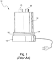
- Fig. 1 depicts a prior art humidifier device 10 with a control base 16, which comprises a heater plate 18.
- a water tub 12 comprising an air inlet 20, an air outlet 22 and a heat conductive tub base 14, is adapted to sit upon the heater plate 18 of the control base 16.
- the base systems typically comprise a spring loaded heater plate 18 on to which the water tub 12 is attached.
- the spring loaded heater plate 18 ensures good thermal contact with the tub base 14 of the water tub 12, although some thermal losses occur between the heater plate 18 and the water tub 12.
- the Fisher & Paykel HC200TM system and the Respironics RemStarTM heated humidifier have spring loaded heater plates.
- such spring loaded heater plates can provide a friction force against insertion of the water tub, which may make installation of the water tub difficult for some users, especially older or frail users.
- the water in the water tub 12 is heated via thermal conduction between the heater plate 18 and the tub base 14 of the water tub 12.
- the tub base 14 is commonly formed of aluminium or stainless steel.
- the tub base 14 is generally formed as a separate component of the water tub 12 and sealingly coupled to the upper portion of the water tub, for example using adhesives or a stamped rolled edge. For example, see Applicant's WO 2007/019626 A1 .
- heaters are known but have rarely, or not at all, been used in commercially available respiratory humidifiers to date.
- One example is induction heaters as described in Applicant's WO 2007/101298 A1 .
- layered heaters are also known and have been used in a range of applications including defogging mirrors, screens for televisions, video cameras & mobile phones and blanket heaters.
- printed thick film heating elements that comprise conductive and resistive inks, such as carbon ink or silver ink, have been used.
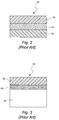
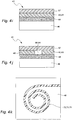
- Fig. 2 shows the general construction of a printed thick film heating element 28 comprising a first film substrate layer 30 with a conductive and resistive inks layer 34 printed thereon and then a second film 32.
- the two films 30, 32 are laminated together with a pressure sensitive adhesive sandwiching the ink layer 34.
- the films are typically thermoplastic or thermoset polymers such as polyester or polyimide.
- Such flexible layered heaters may be attached to the required surfaces to provide the required heating function.
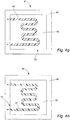
- Labels are commonly used to provide decorative designs, branding, texture, instructions, warnings and other such graphical material to products.
- In-mold labeling is a method used to attach the labels to the surface of a molded object wherein the label is attached within the wall of a molded object.
- In-mold labeling is used with blow molded and injection molded products such as toys, containers for cleaning products, motor oil, beverages and the like.
- the label is printed onto a film using known printing techniques such as flexography, offset, screen or hot stamping printing.
- U.S. Patent 6,551,671 (Nishizawa et al. ) describes a process for in-mold labeling.
- Fig. 3 illustrates the general construction of an in-mold label 35 where a graphic 38 is printed upon a film 36.
- the formed printed film 36, 38 is placed and held within an open mold with the film 36 surface adjacent to the mold.
- the mold is closed and the hot mold resin 40, such as a plastic polymer, is extruded or injected into the mold to form the desired object shape with an integrally molded label.
- the film 36 is generally comprised of a polypropylene or polyethylene copolymer that comprises a heat-activated adhesive that facilitates attachment of the printed film within the wall of the molded object.
- WO 2006/012878 A1 discloses an evaporator having a housing for receiving a liquid and a heater.
- the heater has a plurality of heating elements which can be individually heated.
- artificial respiration apparatuses comprising these evaporators and an evaporation process.
- WO 2002/13578 A1 discloses a modular fluid heating apparatus assembled from a plurality of modular heating components.
- Each modular heating component includes a first molded section defining a first opening therethrough and a second molded section defining a second opening therethrough. The first and second openings are aligned to form a fluid tight passage through the modular heating component.
- a resistance heating element is secured between the first and second molded sections in the enclosed area.
- the resistance heating element includes a supporting substrate having a first surface thereon and an electrical resistance heating material fastened to the first surface of the supporting substrate.
- Conventional humidifiers have the disadvantage of many different components that require assembly and increase weight.
- the assembly of different components and the use of heater plates and tubs with conductive base plates provides an increased risk of water leakage.
- the present invention seeks to address one or more of these disadvantages or at least provide a reasonable alternative.
- the present invention relates to a humidifier according to claim 1.
- the aspects and embodiments not covered by the scope of claim 1 are disclosed for illustrative purposes only.
- An aspect of the invention is directed to a heater element that provides safe and effective heat. Another aspect of the invention provides a heater element that is molded within a container during manufacture. A further aspect relates to an in-mold heater element comprising a polymer film having electrically conductive ink printed upon at least one surface. In another aspect the electrically conductive ink is carbon and/or silver ink. In a further aspect the polymer film is a polyester, polyimide, polycarbonate or polypropylene.
- a heater element comprising a polymer film having an electrically conductive ink printed upon at least one surface wherein the polymer film is molded into at last one surface of the molded object.
- the heater element comprises electrical connectors fastened to the electrically conductive ink to provide power and/or control signals.
- the heater element comprises sensors such as a temperature sensor for controlling the temperature of the heater element.
- a thermal fuse to provide a protection system to protect against over heating of the heater element.
- Another aspect of the invention relates to a method for manufacturing an object comprising an in-molded heater element.
- the object is formed by injection molding.
- the object is formed by extrusion molding.
- Another aspect of the invention relates to a method for manufacturing a humidifier comprising an in-mold heater element.
- the humidifier has a reduced number of parts and/or simple assembly process.
- Yet another aspect of the invention relates to a respiratory humidifier comprising a heater formed from an in-mold heater element.
- Still another aspect of the invention relates to an electrical heater having simple electrical connections.
- a heater element comprises a first polymer film having an electrically conductive circuit provided upon a surface.
- the first polymer film is electrically insulating and is molded into at least one surface of a molded object.
- a method of manufacturing an in-mold heater element comprises i) providing an electrically conductive circuit on a first surface of a first polymer film; ii) placing the first polymer film including the electrically conductive circuit in a mold such that a second surface of the first polymer film opposite the first surface is adjacent the mold; and iii) insert molding resin to form a predetermined molded shape such that the first polymer film is incorporated within at least one surface of the molded shape.
- a humidifier comprises a tub configured to contain a supply of water; and a heater comprising a first polymer film having an electrically conductive circuit provided upon a surface.
- the first polymer film is electrically insulating and the tub is formed of molded resin and the heater is molded at least partially within the resin.
- a method of humidifying a flow of pressurized breathable gas comprises passing the flow of pressurized breathable gas over a supply of water contained in a tub, wherein the tub is formed of molded resin and a heater comprising a first polymer film having an electrically conductive circuit on a first surface is molded at least partially within the resin.
- a molded object comprises a heater element, the heater element comprising a first polymer film having an electrically conductive circuit upon a surface.
- the first polymer film is molded into at least one surface of the molded object.
- a control system configured to control a temperature of the heater element.
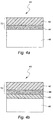
- Fig. 4a illustrates the general construction of an in-mold heater element 41 formed according a method of the invention.
- a conductive ink 44 such as carbon ink or silver ink, is printed upon the surface of a film 42.
- the combined printed film and heater element 72 is then placed within an open mold with the film 42 adjacent the mold.
- the mold is closed and mold resin 46 is injected or extruded into the closed mold to form the desired object.
- the resulting molded object has a printed film heater element 72 molded within the wall of the object.
- the film 42 is a thermoplastic or thermoset polymer material such as polyester, polyimide, polycarbonate, polypropylene or other polymers that provide good thermal conductivity together with electrical insulation properties and mechanical protection of the printed ink.
- the film is thick enough to provide a stable film for the printed ink while still providing sufficient heat transfer.
- the film may have a thickness between 0.01 mm to 1 mm, for example between 0.05 mm to 0.5 mm.
- a second film 43 may be used to sandwich the conductive ink 44 to provide a protective layer between the conductive ink 44 and the molding resin 46.
- the second film 43 may also be formed from a thermoplastic or thermoset polymer material.
- the second film 43 may be electrically insulating, similarly to the film 42.
- the second film 43 may be resistive or conductive as described in more detail below.
- a second layer 45 of protective ink is printed over the conductive ink 44 to provide a protective layer.
- the electrically conductive ink may be carbon ink or silver ink or any other suitably electrically conductive ink.
- the conductive ink is generally printed in a thickness of about 5 ⁇ m to 40 ⁇ m, for example about 10 ⁇ m to 25 ⁇ m. However, larger or smaller conductive ink thicknesses are considered within the scope of the invention.
- the electrically conductive ink is printed on to the film using a screen printing process. However, it should be appreciated that other printing processes may be used, for example etching.
- the pattern of the conductive ink affects the distribution of the heat and the resistance in the circuits.
- the pattern of the electrically conductive ink applied to the film may be adjusted to provide different power densities.
- the thickness, width, length, and material properties (resistivity/conductivity) of the electrically conductive ink pattern determines the resistance in the circuit. A thicker or wider ink pattern has lower resistance than thinner or narrow ink patterns, whereas the resistance increases with increasing lengths of the conductive ink pattern.
- the ink pattern is designed to provide a given resistance to allow a particular voltage to be applied to the circuit.
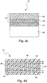
- the electrically conductive ink may be applied in a series of parallel bands linked with a perpendicular band, for example at bands periphery, or the ink may be applied as a single continuous circuit.
- Fig. 4d illustrates an ink pattern having a series of linked parallel bands.
- the arrows represent the electrical connections that are made to the ends of the circuit. It is to be understood that this is only a sample and other ink patterns are considered within the scope of the invention.
- the conductive ink circuits may include a combination of conductive inks such as carbon and silver ink to provide different resistance properties within the heating element.
- Carbon ink has a much higher resistance compared to silver ink.
- carbon ink 47 may be used to form the series of parallel bands, as shown in Fig. 4d
- silver ink 49 may be used to link the carbon ink bands 47 at their periphery.
- Fig. 4e illustrates an ink pattern having a single continuous circuit. As in Fig. 4d , the arrows represent the electrical connections that are made to the ends of the circuit. It is also to be understood that this is only a sample of a continuous circuit and other ink continuous patterns are considered within the scope of the invention.
- the conductive ink circuit may also include other conductive element components such as metal bands to link a series of conductive ink bands, or for the electrical connections.
- Fig. 4f shows a heater element 72 comprising a first layer of film 42a having a conductive ink 44 printed thereon and a metal layer 70 laid over the ink 44 on the first layer of film 42a.
- a second film 42b is laminated to retain the metal layer 70.
- Any conductive metals or alloys may be used, for example copper, gold and nickel chrome, or any other electrically conductive metal.
- the heater element circuit may be formed of, for example, conductive or resistive polymer film or an overmolded layer instead of, or in addition to, the conductive ink.
- the heater element 41 may include a circuit formed of a conductive or resistive polymer film 43 that may be stamped to provide the circuit pattern.
- the conductive or resistive polymer film 43 circuit may be provided on a polymer film 42 to form a stamped film heater element 73.
- the heater element circuit may be formed by overmolding 57 the pattern of the circuit onto the film 42 to form an overmolded film heater element 75.
- the overmold layer 57 may be formed of a resistive or conductive material.
- heater element 41 and control circuit therefor may be formed by any combination of conductive ink 44, conductive or resistive polymer film 43, and/or overmolding 57. It should be further appreciated that the heater element 41 and control circuit may be used, for example, with the metal layer described above with respect to Fig. 4f .
- the heater element circuit and/or the control circuit may be formed of multiple layers of conductive ink, conductive or resistive polymer film(s), and/or overmolding to control the thermal properties.
- the heater element circuit may be formed of conductive ink(s) 44, and a film or foil 43 may locate, connect, and/or thermally protect a thermal sensor 90, 94, e.g. a thermistor.
- the thermal sensor may then be overmolded 57 to control the thermal properties of the sensor, and/or to insulate the sensor from the water of a humidifier tub.
- the heater element may be either a printed film heater element 72, a stamped film heater element 73, and/or an overmolded heater element 75 and may be formed in a shape, for example a spiral, that is configured to cause differential heating to thereby cause water currents to form.
- the heater element may be configured to create a swirling flow.
- the heater element may be formed with portions causing differential heating in areas of a humidifier where water flow may tend to be reduced, or stagnant, compared to other portions of the humidifier.
- any suitable molding resin may be used, including such resins as polycarbonate, polycarbonate ABS blends such as AstaloyTM, polyethylene and polypropylene.
- the molded object 46 may be formed using extrusion molding or injection molding techniques or any other appropriate molding techniques.
- the molded object 46 comprising the in-mold heater 41 of the invention, including the printed film heater element 72, the stamped film heater element 73, and/or the overmolded heater element 75, may be made into any desired shape and may be used for a range of heating applications, for example, water baths, heaters, heating racks, syringe heaters, humidifiers, heated containers such as battery heaters and other suitably moldable objects and products.
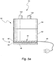
- the in-molded heater element 41 is formed within a humidifier device, for example in a respiratory humidifier device 51.
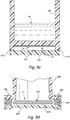
- Fig. 5a shows an embodiment of the in-mold heater element 41 of the invention used in a respiratory humidifier device 51.
- the conductive ink 44 is printed onto a film 42 and the subsequently formed printed ink film heater element 72 is molded into the base and/or sides of a humidifier tub 50 during the molding of the humidifier tub 50.
- the humidifier tub 50 comprises an upper portion 54 and a lower portion 52.
- the lower portion 52 comprises the in-mold heater element 41 at the base of the humidifier tub 50.
- the in-mold heater element 41 may be formed in any portion of the humidifier tub 50, for example in the sides, base, top or combinations thereof.
- an in-mold printed heater element 41 may be used to heat the air passing through the humidifier to enhance the moisture uptake by the air, or to adjust the temperature of the delivered air.
- the upper portion 54 of the humidifier tub 50 comprises an air inlet 120 and an air outlet 122.
- the air inlet 120 or air outlet 122 or both may be located in the lower portion 52.
- the upper portion 54 may be formed as a removable lid to allow ease of cleaning and/or filling of the tub with water.
- the upper portion 54 may be permanently fastened to the lower portion 52, for example by welding or gluing or any other techniques known to sealingly fasten components.
- a seal may be used between the upper portion 54 and the lower portion 52 to reduce the risk of water leakage.
- the joint between the upper portion 54 and the lower portion 52 may be located above the maximum water fill line of the humidifier tub 50 to reduce the likelihood of water leakages from the humidifier tub 50.
- Electrical connections 48 provide power to the in-mold heater element 41 may be formed as part of the molding process within the humidifier tub, as described in more detail below.
- the electrical connections 48 are attached to a power source and/or control source and are located above the maximum water fill line of the humidifier tub.
- the molded respiratory humidifier may be configured as a stand-alone humidifier device or designed as an integrated device for attachment to a related product such as a PAP device, for example in a similar manner to the ResMed S8TM PAP device and the HumidAireTM 3i humidifier device. It should be appreciated that the in-mold heater elements may be molded into any appropriately molded object that requires a heater element.
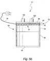
- FIG. 5c A sample humidifier tub embodiment is shown in Fig. 5c , in which the in-mold heater element 41 is not located within the inner surface of the humidifier tub 150 but on an exterior surface of the tub 150.
- the in-mold heater element 41 may be molded into the exterior surface of the base of the tub 150 as described above or the heater element 41 may be a printed ink film heater element 72 in the form of a thick film heater that is attached to the base of the tub 150, for example using adhesives.
- the tub 150 also comprises a base cover 176 that is attached to the base of the tub 150. In one embodiment the base cover 176 is sealed at contact points 178 to the allow ease of cleaning of the tub, for example in a dishwasher, without disturbing the heater element 41.
- a cavity 174 is formed between the heater element 41 and the base cover 176 to provide insulation. Insulating material may be inserted into the cavity 174 to prevent the heat transferring to the base cover 176. This embodiment allows easy access to electrical connections as they are provided on the exterior surface of the tub.
- FIG. 5d Another sample embodiment for a humidifier tub is shown in Fig. 5d .
- the humidifier tub 250 is molded with an open base.
- a heater element 41 is located in the base of the humidifier tub 250 and a base cover 276 is attached to the base of the humidifier tub 250.
- the base cover 276 may be attached to the base of the humidifier tub 250 using a clamp 290 around the bottom perimeter.
- a seal 278 may be located between the humidifier tub 250 and the base cover 276 to prevent water leakage.
- the clamp 290 may permanently attach the base cover 276 to the humidifier tub 250, for example using an adhesive or rolled edge clamp. Alternatively, the clamp 290 may allow removal of the base cover 276 for cleaning or disinfecting purposes.
- the clamp 290 may be in the form of a screw-on or press-fit arrangement or one or more clips. Furthermore, the clamp 290 may be formed as an integral part of the base cover 276, for example in the form of a screw-on base cover (not shown).
- the heater element 41 may be molded into the base cover 276 as described above or positioned in the base of the humidifier as a laminated heater element 272.
- the laminated heater element 272 may be attached to the base cover 276, for example using adhesives, or positioned above the base cover 276 to provide a cavity 274 under the laminated heater element 272.
- the laminated heater element 272 may provide the internal base of the humidifier tub 250 such that water in the tub cannot flow under the laminated heater element 272.
- the cavity 274 under the heater element may provide an insulating layer to protect the base cover 276 from excess heat.
- the laminated heater element 272 may be positioned within the humidifier tub 250 to allow water to flow on both sides of the heater element 272 allowing heating of water on both sides of the heater element 272.
- the in-mold heater element 41 requires electrical connections for operation of the heater element. Access to at least a portion of the in-molded heater element 41 or a connector attached to the heater element 41 is required at a suitable external position of the molded object (e.g. humidifier tub), to enable connection to a power supply unit.
- the electrical connector construction must establish an electrical connection between the heater element circuit, e.g. conductive ink, conductive or resistive polymer film, and/or overmolding, and an electrical contact.
- the electrical connections are molded into the object together with the heater element during the molding process.
- the electrical connections may be via a direct contact to the heater circuit or via connection to additional components, such as electrical wire or a metal contact.
- Figs. 6a - 6e show sample embodiments for the electrical connection.
- the film 42 comprising the heater element circuit e.g. printed conductive ink layer 44 of printed ink film heater element 72, is shown molded into the mold resin 46.
- Figs. 6a, 6b and 6c show examples of direct access 60 to the in-mold heater element 41, e.g. to the conductive ink 44, for direct contact to an electrical tab or connector, for example on a base unit or stand unit.
- the in-mold heater element 41 would be placed upon a complementary shaped tab or connector that may be connected to a power supply unit or electrical plug.
- the molded resin 46 is shaped to form the recess 60.
- the film 42 and the conductive ink 44 are exposed in a section of the mold such that no mold resin 46 is formed on a portion of the printed films.
- Figs. 6d and 6e show the use of additional components for the electrical connection.
- Fig. 6d shows an electrical wire 62 fastened to the conductive ink 44 on the film 42.
- the electrical wire 62 may be fastened to the conductive ink 44 on the film 42 using techniques for fastening electrical connections, such as crimping or terminal blocks.
- the fastened electrical wire 62 may include a rigid mechanical contact connector, for example a plug and socket type connector, such as a spade or bullet connector, for the connection to the conductive ink 44 on the film 42.
- the electrical wire 62 is fastened to the conductive ink 44 on the film 42 prior to the molding step with the mold resin.
- the electrical connection and electrical wire 62 is molded into the molded object together with the conductive ink 44 on the film 42.
- a conductive material 64 such as a metal contact, is fastened to the conductive ink 44 on the film 42 and the conductive material 64 is exposed on the outer surface of the molded object 46 to provide a direct electrical contact for a complementary electrical contact on a base or stand unit as described above for embodiments shown in Figs. 6a-6c .
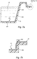
- Fig. 7a shows a humidifier tub 350 having a heater element 41 molded into the molded humidifier tub 350.
- the heater element 41 may be a printed ink film heater element 72 and be formed in the base 351 of the humidifier tub 350 and extend up at least one of the sidewalls 352.
- the sidewall 352 is molded with the heater element 72 to provide an external access for the electrical power and control connections above and/or away from the water W in the humidifier tub 350.
- Fig. 7b shows an alternative arrangement for providing access for the electrical connections where the heater element 72 is molded through the humidifier tub sidewall 352.
- the heater element 72 is shown on the upper surface of the sidewall 352, however it may also be provided on the lower surface.
- the electrical connector for the molded object may be formed using features of the in-molded heater element 41, e.g. a printed ink film heater element 72.
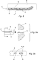
- Fig. 8 shows an embodiment of a connector region.
- the connector region comprises a film 42 having the conductive ink layer 44 printed thereon and then having a further layer of metal 70 laid over the conductive ink layer 44.
- the molded resin 46 is added around the heater element 72 to form the molded object, e.g. humidifier tub.
- the molded resin 46 is formed on the internal surface of the object and the heater element 72 is on the external surface.
- the molded resin 46 provides the structural and physical support for the electrical connection.
- the molding may also be designed to provide guiding assistance when the heater element connector is engaged with the power supply connector.
- the metal layer 70 may be exposed on the external surface to provide a conductive contact connector.
- Figures 9a and 9b show an example of a mating connector design.
- the in-mold heater element 41 e.g. a printed ink film heater element 72 as described above, is formed within an exposed surface of the molded object 46.
- a complementary shaped connector portion is formed in the power supply unit 74.
- a spring contact 76 on the power supply unit 74 provides electrical connection to the exposed contact, e.g. metal layer 70, on the heater element 72 in the molded object 46 when the molded object 46 is inserted in direction 78 into the power supply unit 74.
- Figure 9b shows a cross-section of the contact portions of the molded object.
- the shape of the molded connector region may be used to provide alignment for the connectors.
- the alignment portions may be formed in different shapes as indicated by 80 and 82.
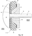
- Figure 10 shows another sample embodiment for the electrical connector construction to provide an electrical connection between the heater element and an electrical contact.
- an electrical connector 81 having a pin-like structure 83 with a head portion 85 that is inserted through the molded object 46 and the in-mold heater element 41, e.g. a printed ink film heater element 72.
- the pin portion 83 of the electrical connector 81 is inserted from the interior of the molded object 46 until the head portion 85 is positioned against an internal surface of the molded object 46.
- the electrical connector 81 is molded into the molded object 46 during manufacture.
- the electrical connector 81 is inserted after the molded object 46 is made.
- the electrical connector 81 contacts the heater element circuit, e.g.
- a securement unit 84 is attached to the pin portion 83 of the electrical connector 81 to provide an increased electrical conductive interface 42a and to secure the electrical connector 81 in position.
- the securement unit 84 may be in the form of a screwed, riveted or glued adaptor, or the like. Seals 86 may be provided to ensure a secure and safe connection.
- the electrical connector may be above the water level in a humidifier tub.
- the level of heating by the in-mold heater elements may be controlled using a temperature sensor such as a thermistor or thermocouple.
- the in-mold heater 72 includes one or more thermistors 90, 92 electrically in series with the power supply and the printed conductive ink 44 on the film 42.
- a positive temperature coefficient (PTC) thermistor or a negative temperature coefficient (NTC) thermistor may be used to control the level of heating.
- a PTC thermistor operates to decrease the heating power to the heater element as the temperature increases towards the desired temperature.
- a PTC thermistor may be used in a respiratory humidifier device.
- a temperature sensor 94, or thermistor, or conductive thermoplastic elastomer (PTC-TPE) with PTC electrical properties may be molded into the molded object 46 together with the heater element circuit, e.g. conductive ink 44, on the film 42, as shown in the sample embodiment depicted in Fig. 12 .
- PTC-TPE conductive thermoplastic elastomer
- a thermal fuse 96 may be incorporated with the conductive ink 44 on the film 42 in a proximity close to the surface of the heater 72 to guard against overheating.
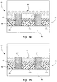
- a humidifier tub 50 may include an in-mold heater element comprising, for example, a stamped film heater element 73 including a stamped resistive or conductive polymer film 43 and the polymer film 42.
- the tub 50 may also include an overmold material 57 that separates portions 43a, 43b, 43c of the polymer film 43.
- the water level W When the water level W is above the overmold material 57, the water forms a conductive circuit with the portions 43a, 43b, 43c of the polymer film 43, as shown in Fig. 14 .
- the conductive path between the portions 43a, 43b, 43c is broken.
- the polymer film 43 may thus be used as a water level sensor.
- an amp meter may be connected to the polymer film 43.
- the electrically conductive ink may be used instead of, or in addition to, the polymer film 43.
- the polymer film 43 may be replaced by, for example, a conductive ink foil.
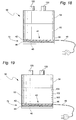
- the humidifier tub 50 may include a printed ink film heater element 72 that comprises a conductive ink 44 and a polymer film 42.
- the humidifier tub 50 may also include an overmolded material 57 formed over the heater element 72.
- the overmolded material 57 may include a mound(s), or "volcano(es)", 57a that is formed above the remainder of the overmolded material 57.
- the mound 57a may include, for example, another heater, including another printed ink film heater 72 or a stamped film heater 73, thermistors 90 or 92, temperature sensors 94 or 98, and/or thermal fuse(s) 96.
- the additional heater element 72 or 73 may be electrically conductive when the water level W is above the overmolded mound(s) 57a, as shown in Fig. 16 , and electrically non-conductive when the water level W is below the mound(s) 57a, as shown in Fig. 17 .
- the mound(s) 57a may allow the additional heater element 72 or 73 to operate as a water level sensor as described above.
- the thermistors 90 or 92 and/or the temperature sensors 94 or 98 may act as a water level sensor. For example, when the water level falls below the overmold mound(s) 57a, a large temperature differential may be sensed that indicates the water level has dropped below the mound(s) 57a.
- a temperature sensor 98 may be positioned adjacent the base of a humidifier tub and may be used to provide an indication of the water level. For example, if the water level is very low the heater element will heat up very rapidly.
- Other sensors, such as humidity sensors, may also be included within the molded object on the heater element to provide an indication of the level of humidification. Sensors may be loaded on to the heater element in contact with the conductive ink using conductive adhesives and covered with an epoxy for protection. Temperature sensors molded into different portions of a molded object may also provide an indication of the flow rate by detecting the temperature and rate between two temperature sensors.
- a humidifier tub may comprise a lower portion 52 and an upper portion 54.
- the upper portion 54 may comprise an air inlet 120 and an air outlet 122.
- the lower portion 52 may comprise a printed film heater element 72, although it should be appreciated that the heater element may be a stamped film heater element or an overmolded film heater element as described above.
- the lower portion 52 may comprise a plurality of temperature sensors 98, 100, 102, 104. As the water level in the lower portion 52 goes down, each sensor 104, 102, 100, 98 will be successively exposed to air flow through the humidifier. The change in the detected temperature, from water to air flow, provides an indication of the water level.
- the heater element 72 may extend along a side wall of the lower portion 52 of the humidifier tub 50 and include a plurality of sensors 98, 100, 102, 104 provided in the heater element to provide an indication of the water level.
- the heater element 72 will heat up more rapidly in areas not exposed to water in the lower portion 52 and the sensors in the areas of the heater element not exposed to water will indicate higher temperatures.
- the circuit of the heater element 72 may also include, for example, a thermistor and/or a thermal fuse, as described in relation to other embodiments.
- the heater element may be a stamped film heater element or overmolded film heater element as also described above.
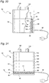
- the humidifier tub 50 may comprise the upper portion 54 and the lower portion 52.
- the upper portion may also comprise a thermal sensor, or sensors, 106, 108, 110.
- the thermal sensor(s) 106, 108, 110 may be placed above the water level, for example a maximum fill level defined in the lower portion 52, to detect a temperature of the air in the upper portion 54. If the air temperature exceeds a predetermined temperature, for example 40°C, the power provided to the heater element 72 may be controlled to lower the air temperature.
- the heater element 72 may be provided in a base of the lower portion 52, as shown in Fig. 21 , or the heater element 72 may be configured as in Fig. 20 . It should further be appreciated that any positive number of temperature sensors 106, 108, 110 may be provided, and temperature sensors may be provided at multiple locations in the upper portion 54 of the humidifier tub 50. For example, a temperature sensor may be provided at the inlet 120 and/or the outlet 122 to provide control of the heater element. As the inlet air temperature changes, the power supplied to the heater element 72 may be controlled to maintain a predetermined temperature at the outlet.
- the film may also include a water level sensor.
- a water level sensor including cathodic probes or a thermal gradient using temperature sensors, may be included in the molded object, e.g. humidifier tub.
- the sensors would rely on the thermal relationship between the heater and the water, and the ability to mold the shape of the molded object to accommodate the mechanical requirements of the humidifier.
- a humidity sensor(s) either an absolute and/or a relative humidity sensor may be provided in the humidifier to allow for control of the heater element.
- Such a control system is disclosed in, for example, U.S. Applications 61/034,318 and 61/042,112 , filed March 6, 2008 and April 3, 2008, respectively.
- the heaters may also be zoned.
- the heaters may be provided on the film or overmolded material to include a water heating section and an air heating section.
- Each heater in each zone may include separate sensing, control, and/or thermal protection elements provided on the film.
- the zoning may also be horizontal for sensing and heating. Horizontal zoning would allow heating of the surface of the water only to improve warm up time and reduce energy losses.
- an electronic circuit, or circuits may be provided on the film or overmolded material and molded into the molded object.
- switching control elements may be provided on the film or overmolded material to recover heat losses that would normally be dissipated. The recovered heat may be used to heat the water in the humidifier chamber.
- the power supply may be a stand alone power supply unit or incorporated within a supplementary device, such as PAP device that provides the power and electrical control systems for the device comprising the in-mold heater, such as an integrated humidifier device.
- the power supply unit forms a component of a humidifier device.
- in-mold heater elements may provide a number of advantages over conventional heating technologies, including lower cost, ease of manufacture, reduced weight and increased efficiency.
- the ability to mold the heater element within the molded object results in a reduction in the number of components and the time and complexity of assembly of the complete object. Hot plate and heat conductive plates are no longer required but are combined as the in-mold heater element performs the equivalent function. Such reductions may also lead to a significant cost savings.
- the heater element may be included exactly where the heating is required there may be an increase in heating efficiency and response time. Molding the heater elements within the molded object also minimizes the chance of leakage in molded objects designed to hold fluids, such as humidifiers.
- the use of an in-mold heater element may have some significant benefits.
- the humidifier may no longer require a cradle or chassis unit, which conventionally includes the hot plate and the structural features to secure the humidifier tub to ensure good thermal contact between the humidifier tub base and the hot plate.
- a humidifier tub base seal is no longer required and leakage problems should be reduced, or minimized.
Claims (14)
- Befeuchter (10) mit:einer Wanne (12; 50; 150; 250; 350), die dafür konfiguriert ist, einen Wasservorrat aufzunehmen; undeiner Heizeinrichtung (18; 41; 72; 73; 75; 272), die eine erste Polymerschicht (42) mit einer Oberfläche und eine auf der Oberfläche bereitgestellte elektrisch leitfähige Schaltung (43) aufweist, wobei die elektrisch leitfähige Schaltung mindestens eine Komponente aufweist unter einer elektrisch leitfähigen Tinte, einer zweiten leitfähigen oder resistiven Polymerschicht und einem leitfähigen oder resistiven Material, das umspritzt ist, wobei die erste Polymerschicht (42) elektrisch isolierend ist und die Wanne (12; 50; 150; 250; 350) aus Gießharz ausgebildet ist und die Heizeinrichtung (18; 41; 72; 73; 75; 272) mindestens teilweise innerhalb des Harzes ausgeformt ist.
- Befeuchter nach Anspruch 1, wobei die elektrisch leitfähige Tinte Kohlenstofftinte, Silbertinte oder eine Kombination davon ist.
- Befeuchter nach Anspruch 1 oder 2, wobei die Schaltung (43) aufweist:ein einzelnes kontinuierliches Muster wie eine Spirale oder eine Helix; odermehrere parallele Streifen, die durch mindestens einen Streifen verbunden sind, der sich senkrecht zu den parallelen Streifen erstreckt, und wobei die parallelen Streifen aus Kohlenstofftinte ausgebildet sind und der mindestens eine senkrechte Streifen aus Silbertinte oder aus einem Metall ausgebildet ist.
- Befeuchter nach einem der Ansprüche 1 bis 3, wobei die Wanne (12; 50; 150; 250; 350) einen oberen Abschnitt (54) und einen unteren Abschnitt (52) aufweist, wobei der obere Abschnitt (54) vom unteren Abschnitt (52) entfernbar ist und der obere Abschnitt (54) einen Einlass (120) und einen Auslass (122) für einen Strom von atembarem Gas aufweist.
- Befeuchter nach Anspruch 4, wobei die Heizeinrichtung (18; 41; 72; 73; 75; 272) im oberen Abschnitt (54) oder im unteren Abschnitt (52) unterhalb einer maximalen Wasserfülllinie der Wanne angeordnet ist.
- Befeuchter nach einem der Ansprüche 1 bis 5, ferner mit einem elektrischen Verbinder (81), der dafür konfiguriert ist, die Heizeinrichtung mit einer Stromversorgung zu verbinden, wobei der elektrische Verbinder aufweist:einen freiliegenden Abschnitt der Schaltung, der dafür konfiguriert ist, mit einem elektrischen Kontakt der Stromversorgung in Kontakt zu kommen; odereinen mit der Schaltung verbundenen und teilweise in das Harz eingegossenen Draht, wobei der Draht durch eine befestigende elektrische Verbindung, wie z.B. Crimpen, oder Klemmenleisten, oder durch einen mechanischen Kontaktverbinder, wie beispielsweise einen Steckverbinder, wie einen Flach- oder Rundverbinder, mit der Schaltung verbunden ist; oderein leitfähiges Material, das mit der Schaltung in Kontakt steht und teilweise in das Harz eingegossen ist; oderein stiftartiges Element, das sich durch das Gießharz und die Heizeinrichtung erstreckt, um mit der elektrisch leitfähigen Tinte in Kontakt zu stehen, wobei das stiftartige Element einen Kopf auf einer Innenfläche der Wanne aufweist.
- Befeuchter nach Anspruch 6, ferner mit einer Dichtung zwischen dem Kopf des stiftartigen Elements und der Innenfläche.
- Befeuchter nach einem der Ansprüche 1 bis 7, wobei mindestens ein Abschnitt der Heizeinrichtung auf einer Innenfläche der Wanne oder auf einer Außenfläche der Wanne freiliegt.
- Befeuchter nach einem der Ansprüche 1 bis 8, wobei die Heizeinrichtung einen Temperatursensor wie beispielsweise ein Thermoelement, einen Thermistor mit positivem Wärmekoeffizient oder negativem Wärmekoeffizient odereine Thermosicherung, odereinen Feuchtigkeitssensor, oderein Schaltsteuerelement, odereinen Wasserstandsensor wie beispielsweise eine kathodische Sonde, oder einen Wärmegradient aufweist.
- Befeuchter nach einem der Ansprüche 1 bis 9, wobei die Heizeinrichtung Zonen aufweist, wobei einige der Zonen dafür konfiguriert sind, in der Wanne enthaltenes Wasser zu erwärmen, und einige der Zonen dafür konfiguriert sind, Luft in der Wanne zu erwärmen.
- Befeuchter nach Anspruch 10, wobei jede Zone einen Temperatursensor, einen Feuchtigkeitssensor, einen Wasserstandsensor, eine Thermosicherung und/oder ein Schaltsteuerelement aufweist.
- Befeuchter nach einem der Ansprüche 1 bis 11, wobei das umspritzte Material dafür konfiguriert ist, Abschnitte der elektrisch leitfähigen Tinte und/oder der zweiten Polymerschicht derart zu isolieren, dass bei einem ersten Wasserstand ein leitfähiger Pfad zwischen mindestens einigen der isolierten Abschnitte gebildet wird und bei einem zweiten Wasserstand kein leitfähiger Pfad zwischen irgendwelchen der isolierten Abschnitte bereitgestellt wird.
- Befeuchter nach einem der Ansprüche 1 bis 12, wobei das umspritzte Material mindestens einen Abschnitt aufweist, der dafür konfiguriert ist, mindestens eine Komponente unter einem Temperatursensor, einer Sicherung oder einer zweiten Heizeinrichtung zu tragen, so dass bei einem ersten Wasserstand der Temperatursensor, die Sicherung und/oder die zweite Heizeinrichtung von dem Wasser bedeckt sind, und bei einem zweiten Wasserstand der Temperatursensor, die Sicherung und/oder die zweite Heizeinrichtung nicht von dem Wasser bedeckt sind.
- Beatmungsgerät zum Zuführen eines atembaren Gasstroms zu einem Patienten mit einem Befeuchter nach einem der Ansprüche 1 bis 13.
Priority Applications (1)
| Application Number | Priority Date | Filing Date | Title |
|---|---|---|---|
| EP21157223.5A EP3893600A1 (de) | 2007-06-05 | 2008-06-03 | Elektrische heizvorrichtung mit besonderer anwendung zur befeuchtung und flüssigkeitserwärmung |
Applications Claiming Priority (4)
| Application Number | Priority Date | Filing Date | Title |
|---|---|---|---|
| AU2007902992A AU2007902992A0 (en) | 2007-06-05 | A heater | |
| AU2007903599A AU2007903599A0 (en) | 2007-07-04 | A Heater | |
| US98640407P | 2007-11-08 | 2007-11-08 | |
| PCT/AU2008/000799 WO2008148154A1 (en) | 2007-06-05 | 2008-06-03 | Electrical heater with particular application to humidification and fluid warming |
Related Child Applications (1)
| Application Number | Title | Priority Date | Filing Date |
|---|---|---|---|
| EP21157223.5A Division EP3893600A1 (de) | 2007-06-05 | 2008-06-03 | Elektrische heizvorrichtung mit besonderer anwendung zur befeuchtung und flüssigkeitserwärmung |
Publications (3)
| Publication Number | Publication Date |
|---|---|
| EP2168403A1 EP2168403A1 (de) | 2010-03-31 |
| EP2168403A4 EP2168403A4 (de) | 2011-07-06 |
| EP2168403B1 true EP2168403B1 (de) | 2021-02-17 |
Family
ID=40093073
Family Applications (2)
| Application Number | Title | Priority Date | Filing Date |
|---|---|---|---|
| EP21157223.5A Pending EP3893600A1 (de) | 2007-06-05 | 2008-06-03 | Elektrische heizvorrichtung mit besonderer anwendung zur befeuchtung und flüssigkeitserwärmung |
| EP08756887.9A Active EP2168403B1 (de) | 2007-06-05 | 2008-06-03 | Elektrisches heizelement mit besonderer anwendung auf die entfeuchtung und fluiderwärmung |
Family Applications Before (1)
| Application Number | Title | Priority Date | Filing Date |
|---|---|---|---|
| EP21157223.5A Pending EP3893600A1 (de) | 2007-06-05 | 2008-06-03 | Elektrische heizvorrichtung mit besonderer anwendung zur befeuchtung und flüssigkeitserwärmung |
Country Status (7)
| Country | Link |
|---|---|
| US (3) | US8873941B2 (de) |
| EP (2) | EP3893600A1 (de) |
| JP (3) | JP5946602B2 (de) |
| CN (2) | CN101690385B (de) |
| AU (1) | AU2008258265B2 (de) |
| NZ (4) | NZ704650A (de) |
| WO (1) | WO2008148154A1 (de) |
Families Citing this family (76)
| Publication number | Priority date | Publication date | Assignee | Title |
|---|---|---|---|---|
| DE10139881B4 (de) | 2001-08-20 | 2017-06-08 | Resmed R&D Germany Gmbh | Vorrichtung zur Zufuhr eines Atemgases und Verfahren zur Steuerung derselben |
| US8739780B2 (en) | 2005-08-15 | 2014-06-03 | Resmed Limited | Low cost CPAP flow generator and humidifier assembly |
| AU2007318331B2 (en) | 2006-11-06 | 2012-04-05 | Fisher & Paykel Healthcare Limited | Integrated humidifier chamber and lid |
| CN101690385B (zh) | 2007-06-05 | 2015-05-27 | 瑞思迈有限公司 | 尤其用于加湿和液体加热的电热器 |
| US9802022B2 (en) | 2008-03-06 | 2017-10-31 | Resmed Limited | Humidification of respiratory gases |
| EP2236167B1 (de) | 2009-03-30 | 2011-10-12 | Dräger Medical GmbH | Befeuchtungsvorrichtung für Atemgase |
| AU2010206053B2 (en) | 2009-07-31 | 2014-08-07 | ResMed Pty Ltd | Wire Heated Tube with Temperature Control System, Tube Type Detection, and Active Over Temperature Protection for Humidifier for Respiratory Apparatus |
| US9737682B2 (en) | 2009-09-17 | 2017-08-22 | Resmed Limited | Humidification of respiratory gases |
| US8476562B2 (en) * | 2010-06-04 | 2013-07-02 | Watlow Electric Manufacturing Company | Inductive heater humidifier |
| EP2667919B1 (de) * | 2011-01-24 | 2021-05-26 | ResMed Pty Ltd | Befeuchter |
| EP3714930B1 (de) * | 2011-06-16 | 2023-12-06 | ResMed Pty Ltd | Befeuchter mit geschichtetem heizelement |
| JP2021049476A (ja) * | 2011-06-16 | 2021-04-01 | レスメド・プロプライエタリー・リミテッド | 加湿器 |
| US8839791B2 (en) | 2011-06-22 | 2014-09-23 | Breathe Technologies, Inc. | Ventilation mask with integrated piloted exhalation valve |
| US9486602B2 (en) | 2011-06-22 | 2016-11-08 | Breathe Technologies, Inc. | Ventilation mask with integrated piloted exhalation valve and method of ventilating a patient using the same |
| US9038634B2 (en) | 2011-06-22 | 2015-05-26 | Breathe Technologies, Inc. | Ventilation mask with integrated piloted exhalation valve |
| KR102196913B1 (ko) | 2011-09-06 | 2020-12-30 | 니코벤처스 트레이딩 리미티드 | 가열식 흡연가능 재료 |
| BR112014004818B1 (pt) | 2011-09-06 | 2021-01-05 | British American Tobacco (Investments) Limited. | aparelho para aquecer material fumável e método para aquecer material fumável |
| US20150014874A1 (en) * | 2012-03-01 | 2015-01-15 | Koninklijke Philips N.V. | Method and apparatus for determining a liquid level in a humidified pressure support device |
| CN105307715B (zh) | 2012-03-15 | 2017-11-17 | 费雪派克医疗保健有限公司 | 呼吸气体加湿系统 |
| EP4197582A1 (de) | 2012-03-15 | 2023-06-21 | ResMed Pty Ltd | Wanne für befeuchter |
| GB201207039D0 (en) * | 2012-04-23 | 2012-06-06 | British American Tobacco Co | Heating smokeable material |
| CN107335122B (zh) | 2012-04-27 | 2022-02-18 | 费雪派克医疗保健有限公司 | 用于呼吸增湿系统的可用性特征 |
| CN103391646A (zh) * | 2012-05-11 | 2013-11-13 | 四川汇利实业有限公司 | 一种制作简便的医药原料加热器 |
| EP2864740A1 (de) * | 2012-06-22 | 2015-04-29 | Chromatic Technologies, Inc. | Thermochromer füllstandsanzeiger |
| GB2504731B (en) * | 2012-08-08 | 2015-03-25 | Reckitt & Colman Overseas | Device for evaporating a volatile fluid |
| GB2504733B (en) * | 2012-08-08 | 2015-05-20 | Reckitt & Colman Overseas | Device for evaporating a volatile material |
| DE202013012358U1 (de) * | 2012-09-07 | 2016-06-24 | Fisher & Paykel Healthcare Limited | Befeuchtungskammer für ein Atmungsunterstützungsgerät |
| NZ710078A (en) | 2013-02-01 | 2017-01-27 | Resmed Ltd | Wire heated tube with temperature control system for humidifier for respiratory apparatus |
| US9878121B2 (en) | 2013-03-13 | 2018-01-30 | Breathe Technologies, Inc. | Ventilation mask with heat and moisture exchange device |
| JP5894955B2 (ja) * | 2013-03-25 | 2016-03-30 | エスペック株式会社 | 加湿装置、並びに、環境試験装置 |
| GB2584025B (en) | 2013-09-13 | 2021-03-10 | Fisher & Paykel Healthcare Ltd | Heater plate for a humidification system |
| EP3705151B1 (de) | 2013-09-13 | 2024-04-03 | Fisher & Paykel Healthcare Limited | Verbindungen für ein befeuchtungssystem |
| JP6205580B2 (ja) * | 2013-09-18 | 2017-10-04 | パナソニックIpマネジメント株式会社 | 液体微細化装置とそれを用いたサウナ装置 |
| NZ717147A (en) | 2013-10-21 | 2017-08-25 | Resmed Ltd | Methods of detecting a quantity of water in a humidifier |
| EP3062859B1 (de) | 2013-10-30 | 2022-07-06 | ResMed Pty Ltd | Druckregelung für eine patientenschnittstelle |
| CN103656830A (zh) * | 2013-12-13 | 2014-03-26 | 科迈(常州)电子有限公司 | 一种家用呼吸机加湿器及其湿度控制方法 |
| CN110947066B (zh) | 2013-12-20 | 2023-07-18 | 费雪派克医疗保健有限公司 | 加湿系统连接 |
| DE102014000313A1 (de) * | 2014-01-10 | 2015-07-16 | Audi Ag | Vorrichtung zum Abgeben eines Duftstoffs und Kraftfahrzeug mit einer derartigen Vorrichtung |
| WO2015119515A1 (en) | 2014-02-07 | 2015-08-13 | Fisher & Paykel Healthcare Limited | Respiratory humidification system |
| US10052449B2 (en) | 2014-03-21 | 2018-08-21 | Fisher & Paykel Healthcare Limited | Heating arrangements for humidification systems |
| US9655168B2 (en) | 2014-04-17 | 2017-05-16 | S.C. Johnson & Son, Inc. | Electrical barrier for wax warmer |
| US10616954B2 (en) | 2014-04-17 | 2020-04-07 | S. C. Johnson & Son, Inc. | Electrical barrier for wax warmer |
| US11173272B2 (en) | 2014-05-02 | 2021-11-16 | Fisher & Paykel Healthcare Limited | Gas humidification arrangement |
| CN110124173A (zh) | 2014-05-13 | 2019-08-16 | 费雪派克医疗保健有限公司 | 用于呼吸增湿系统的可用性特征 |
| AU2015269001B2 (en) | 2014-06-03 | 2020-04-30 | Fisher & Paykel Healthcare Limited | Flow mixers for respiratory therapy systems |
| US9857027B2 (en) * | 2014-07-03 | 2018-01-02 | Applied Materials, Inc. | Apparatus and method for self-regulating fluid chemical delivery |
| GB2582875B (en) * | 2014-09-03 | 2021-01-06 | Fisher & Paykel Healthcare Ltd | Deterministically controlled humidification system |
| WO2016080847A1 (en) | 2014-11-17 | 2016-05-26 | Fisher & Paykel Healthcare Limited | Humidification of respiratory gases |
| CN104548308B (zh) * | 2015-01-09 | 2019-03-12 | 北京怡和嘉业医疗科技股份有限公司 | 一种加湿装置、湿化器及呼吸机 |
| US11134544B2 (en) | 2015-07-24 | 2021-09-28 | Rai Strategic Holdings, Inc. | Aerosol delivery device with radiant heating |
| US10206429B2 (en) * | 2015-07-24 | 2019-02-19 | Rai Strategic Holdings, Inc. | Aerosol delivery device with radiant heating |
| US20170055584A1 (en) | 2015-08-31 | 2017-03-02 | British American Tobacco (Investments) Limited | Article for use with apparatus for heating smokable material |
| US11924930B2 (en) | 2015-08-31 | 2024-03-05 | Nicoventures Trading Limited | Article for use with apparatus for heating smokable material |
| US10821257B2 (en) | 2015-10-05 | 2020-11-03 | ResMed Pty Ltd | Respiratory system with humidifier and conformable reservoir |
| CN205287021U (zh) * | 2015-11-18 | 2016-06-08 | 马笑远 | 一种香薰炉 |
| SG11201805302UA (en) * | 2015-12-23 | 2018-07-30 | Fisher & Paykel Healthcare Ltd | Heating arrangements for humidification systems |
| KR102443320B1 (ko) * | 2016-01-05 | 2022-09-15 | 엘지전자 주식회사 | 식기 세척기 및 식기 세척기의 제어방법 |
| DE102016101648A1 (de) | 2016-01-29 | 2017-08-03 | Fresenius Medical Care Deutschland Gmbh | Verfahren zum Regeln einer Heizvorrichtung zum Erwärmen eines Fluids für einen Dialysierflüssigkeitskreislauf, Steuervorrichtung sowie Blutbehandlungsvorrichtung |
| US10647128B2 (en) | 2016-04-21 | 2020-05-12 | Hewlett-Packard Development Company, L.P. | Fluid level sensor |
| CN114534044A (zh) | 2016-05-02 | 2022-05-27 | 菲舍尔和佩克尔保健有限公司 | 用于呼吸辅助设备的加湿腔室和腔室密封件 |
| AU2017278071A1 (en) * | 2016-06-10 | 2018-11-22 | Intrepid Brands, LLC | Oven assembly for personal electronic vaporizer |
| AU2017297977B2 (en) | 2016-07-19 | 2022-10-27 | Fisher And Paykel Healthcare Limited | Water out alarm determination |
| CN106322457B (zh) * | 2016-09-09 | 2018-10-23 | 深圳拓邦股份有限公司 | 一种电磁灶 |
| US10764963B2 (en) | 2016-10-07 | 2020-09-01 | S. C. Johnson & Son, Inc. | Volatile material dispenser |
| CN110072585B (zh) * | 2016-11-22 | 2022-08-05 | 瑞思迈私人有限公司 | 湿化器贮存器 |
| SG10202106016TA (en) | 2016-12-07 | 2021-07-29 | Fisher and paykel healthcare ltd | Sensing arrangements for medical devices |
| FR3061437B1 (fr) * | 2017-01-05 | 2019-01-25 | Air Liquide Medical Systems | Humidificateur pour appareil d'assistance respiratoire |
| US10798783B2 (en) * | 2017-02-15 | 2020-10-06 | Continuous Composites Inc. | Additively manufactured composite heater |
| US20200003601A1 (en) * | 2017-02-23 | 2020-01-02 | Hewlett-Packard Development Company, L.P. | Fluid level sensor |
| FR3064921B1 (fr) * | 2017-04-11 | 2019-03-29 | Air Liquide Medical Systems | Detection de reservoir vide dans un humidificateur chauffant |
| US11351331B2 (en) * | 2017-12-08 | 2022-06-07 | Fisher & Paykel Healthcare Limited | Heater plate for respiratory humidification systems |
| IT201800005586A1 (it) * | 2018-05-22 | 2019-11-22 | Umidificatore attivo e circuito termoregolato integrante tale umidificatore attivo. | |
| DE102018219294A1 (de) * | 2018-11-12 | 2020-05-14 | Magna Exteriors Gmbh | Abdeckelement |
| EP4186552A1 (de) * | 2019-04-17 | 2023-05-31 | ResMed Pty Ltd | Cpap-system mit elastischer dichtung für heizplatte |
| WO2021041298A1 (en) * | 2019-08-23 | 2021-03-04 | Yale University | Portable and compact system for delivery of humidified high flow nasal cannula (hhfnc) therapy in neonates and infants |
| JP7467765B2 (ja) * | 2020-09-08 | 2024-04-15 | レスメド・プロプライエタリー・リミテッド | 携帯用cpapデバイスと共に使用するための加湿プラットフォーム |
Citations (2)
| Publication number | Priority date | Publication date | Assignee | Title |
|---|---|---|---|---|
| WO2002013578A1 (en) * | 2000-08-04 | 2002-02-14 | Watlow Polymer Technology | Modular heat exchanger |
| WO2006012878A1 (de) * | 2004-08-04 | 2006-02-09 | Viasys Healthcare Gmbh | Verdampfer, beatmungsgerät sowie verdampfungsverfahren |
Family Cites Families (102)
| Publication number | Priority date | Publication date | Assignee | Title |
|---|---|---|---|---|
| US1062344A (en) * | 1912-12-17 | 1913-05-20 | Jan Mann | Cooking and domestic utensil heated by electricity. |
| US1839156A (en) * | 1930-02-21 | 1931-12-29 | Edwin K Lumpkin | Seat warmer |
| US3809374A (en) | 1969-06-11 | 1974-05-07 | G Schossow | Vaporizer-humidifier |
| US3672568A (en) | 1970-08-12 | 1972-06-27 | Foote Allen | Humidifier |
| US3694622A (en) * | 1971-01-07 | 1972-09-26 | Ralph L Bentley | Heater |
| CH563000A5 (de) * | 1973-03-09 | 1975-06-13 | Plascon Ag | |
| US4155001A (en) * | 1974-02-21 | 1979-05-15 | Schossow George W | Electrode-type vaporizer |
| JPS566908Y2 (de) | 1974-09-19 | 1981-02-16 | ||
| JPS5538578Y2 (de) | 1977-06-21 | 1980-09-09 | ||
| JPS5538578A (en) | 1978-09-13 | 1980-03-18 | Ricoh Co Ltd | Cathode ray tube exposure type recording device |
| US4222971A (en) | 1978-11-14 | 1980-09-16 | Eilert Richard L | Humidifier liner |
| US4225542A (en) * | 1978-12-12 | 1980-09-30 | Minnesota Mining And Manufacturing Company | Evaporative humidifier |
| DE2925398C2 (de) | 1979-06-23 | 1981-09-17 | Jean Walterscheid Gmbh, 5204 Lohmar | Mehrteilige Schutzvorrichtung an Gelenkwellen |
| US4284878A (en) | 1979-08-20 | 1981-08-18 | Bourns Medical Systems, Inc. | Fluid level detector |
| US4485297A (en) * | 1980-08-28 | 1984-11-27 | Flexwatt Corporation | Electrical resistance heater |
| JPS6133361Y2 (de) | 1981-05-08 | 1986-09-30 | ||
| US4441027A (en) | 1981-08-03 | 1984-04-03 | Baxter Travenol Laboratories, Inc. | Liquid level controller for a respiratory gas humidifier device |
| JPS5968229A (ja) | 1982-10-13 | 1984-04-18 | 旭化成株式会社 | プラスチツクフイルム被覆物及びその製造方法 |
| JPS5968229U (ja) | 1982-10-29 | 1984-05-09 | 三洋電機株式会社 | 液位検出装置 |
| JPS6133361A (ja) | 1984-07-25 | 1986-02-17 | 株式会社ダイフク | 吊下げ搬送設備 |
| US4658448A (en) * | 1985-11-18 | 1987-04-21 | Rogers Jerry W | Process and apparatus for heating baths and the like |
| GB2192136B (en) | 1986-07-04 | 1991-01-02 | Virotherm Lab Ltd | Medical breathing apparatus |
| CA1272502A (en) * | 1986-07-07 | 1990-08-07 | Leonard Ineson | Heated cup |
| US4921642A (en) | 1987-12-03 | 1990-05-01 | Puritan-Bennett Corporation | Humidifier module for use in a gas humidification assembly |
| JPH03115930A (ja) * | 1989-09-29 | 1991-05-16 | Fuji Photo Film Co Ltd | 液面検出装置 |
| US4980539A (en) * | 1990-02-02 | 1990-12-25 | Walton Charles A | Portable warmer |
| JP2572668Y2 (ja) | 1990-03-06 | 1998-05-25 | アイワ株式会社 | テープ走行用ローラガイド装置 |
| US5031612A (en) * | 1990-04-24 | 1991-07-16 | Devilbiss Health Care, Inc. | System and method for delivering warm humidified air |
| DE4107060C2 (de) | 1991-03-06 | 1999-07-01 | Draegerwerk Ag | Dosiervorrichtung für ein flüssiges Narkosemittel über einen Zwischenbehälter |
| US5432322A (en) * | 1992-11-13 | 1995-07-11 | Bruder Healthcare Company | Electric heating pad |
| JP2698318B2 (ja) * | 1993-08-20 | 1998-01-19 | ティーディーケイ株式会社 | ヒータ |
| US5522523A (en) | 1994-02-14 | 1996-06-04 | Southcorp Water Heaters Usa, Inc. | Water heater having flexible liner and method for making the same |
| US5752498A (en) | 1994-10-07 | 1998-05-19 | Lake; Jared L. | Elliptical beam load cell |
| US5546926A (en) | 1994-10-07 | 1996-08-20 | Lake; Jared L. | Whole house humidifier for use with hot air heating systems |
| GB2294187A (en) * | 1994-10-14 | 1996-04-17 | Philips Electronics Nv | Thermal control in a liquid heater |
| JP3092466B2 (ja) * | 1995-01-12 | 2000-09-25 | 松下電器産業株式会社 | 床暖房付き浴室ユニット |
| US5564415A (en) * | 1995-06-07 | 1996-10-15 | Lifecare International, Inc. | Humidifier for a ventilator |
| US6704497B2 (en) * | 1995-09-07 | 2004-03-09 | Bar-Keser Project Management Initiatives And Economic Consultants (1991) Ltd. | Electric heating devices and elements |
| US5981911A (en) * | 1996-04-19 | 1999-11-09 | Thermicon Systems International | Method for heating the surface of a food receptacle |
| GB9611170D0 (en) * | 1996-05-29 | 1996-07-31 | Sls Wales Ltd | Reduction of vascular blemishes by selective thermolysis |
| JPH10234621A (ja) | 1997-02-28 | 1998-09-08 | Dainippon Printing Co Ltd | 暖房便座の製造方法 |
| JPH10312705A (ja) * | 1997-05-14 | 1998-11-24 | Ichikoh Ind Ltd | 合成樹脂製の成形レンズ |
| KR100213110B1 (ko) | 1997-06-12 | 1999-08-02 | 윤종용 | 박막형 발열 히터 및 그 제조방법 |
| US6000224A (en) * | 1998-03-05 | 1999-12-14 | Foye; Matthew R. | Travel mug |
| KR200210798Y1 (ko) * | 1998-03-06 | 2001-11-22 | 박경용 | 발광컵 |
| ATE315819T1 (de) | 1998-04-06 | 2006-02-15 | Yupo Corp | In eine form einzulegendes etikett |
| JP2000028201A (ja) * | 1998-07-07 | 2000-01-28 | Toto Ltd | 熱交換装置及びその製造方法 |
| US6279574B1 (en) | 1998-12-04 | 2001-08-28 | Bunnell, Incorporated | Variable flow and pressure ventilation system |
| US6135427A (en) | 1999-01-08 | 2000-10-24 | Kaz, Incorporated | Humidifier |
| US6263158B1 (en) * | 1999-05-11 | 2001-07-17 | Watlow Polymer Technologies | Fibrous supported polymer encapsulated electrical component |
| AUPQ339099A0 (en) | 1999-10-13 | 1999-11-04 | Resmed Limited | A humidifier |
| US6433317B1 (en) * | 2000-04-07 | 2002-08-13 | Watlow Polymer Technologies | Molded assembly with heating element captured therein |
| US6511050B2 (en) | 2001-05-02 | 2003-01-28 | Dynamo Aviation, Inc. | Humidifier |
| US20030001117A1 (en) | 2001-05-15 | 2003-01-02 | Kwangik Hyun | Dimensional measurement apparatus for object features |
| KR100535680B1 (ko) * | 2001-07-13 | 2005-12-09 | 삼성전자주식회사 | 수위센서 |
| US20030041604A1 (en) | 2001-09-05 | 2003-03-06 | Ching-Shiang Jang | Device for enhancing efficiency of air-conditioner |
| DE10151397C1 (de) | 2001-10-18 | 2002-10-02 | Heptec Gmbh | Verdunster, insbesondere Atemluftbefeuchter, Vorratsbehälter sowie Gehäuse dafür |
| DE50206802D1 (de) * | 2002-02-21 | 2006-06-22 | Ford Global Tech Llc | Beheizbares Bechersystem |
| US7182017B1 (en) * | 2002-04-18 | 2007-02-27 | Bunn-O-Matic Corporation | Beverage server with beverage detector |
| US6953354B2 (en) | 2002-06-05 | 2005-10-11 | Fisher & Paykel Healthcare Limited | Connector for breathing conduits |
| EP3632493B1 (de) | 2002-09-17 | 2021-01-06 | Fisher & Paykel Healthcare Limited | Gerät zur abgabe von befeuchteten gasen |
| TW580892U (en) * | 2002-11-25 | 2004-03-21 | Jiun-Guang Luo | Thermos cup |
| US6870135B2 (en) * | 2003-01-14 | 2005-03-22 | Hlc Efficiency Products Llc | Beverage container warmer |
| US7049558B2 (en) * | 2003-01-27 | 2006-05-23 | Arcturas Bioscience, Inc. | Apparatus and method for heating microfluidic volumes and moving fluids |
| US7019261B2 (en) | 2003-02-06 | 2006-03-28 | Delphi Technologies, Inc. | Apparatus and method for a steering wheel with a preformed heating element |
| KR100526206B1 (ko) * | 2003-03-21 | 2005-11-08 | 삼성전자주식회사 | 조리장치 |
| FR2856046B1 (fr) | 2003-06-16 | 2005-07-29 | Biomerieux Sa | Microvanne fluidique a ouverture par commande electrique |
| AU2003903139A0 (en) | 2003-06-20 | 2003-07-03 | Resmed Limited | Breathable gas apparatus with humidifier |
| CA2912125C (en) | 2003-06-20 | 2019-07-23 | Resmed Limited | Breathable gas apparatus with humidifier |
| WO2005011556A2 (en) | 2003-07-28 | 2005-02-10 | Salter Labs | Respiratory therapy system including a nasal cannula assembly |
| US20050150491A1 (en) * | 2004-01-13 | 2005-07-14 | Yu-Yu Chen | Steam inhaler |
| KR200359944Y1 (ko) | 2004-05-06 | 2004-08-27 | 김영오 | 벽걸이형 초음파 가습기 |
| ATE403411T1 (de) * | 2004-06-14 | 2008-08-15 | Matsushita Electric Works Ltd | Dampferzeuger |
| DE102004037698A1 (de) | 2004-08-02 | 2006-03-16 | Seleon Gmbh | Verdunster sowie Verdunstungsverfahren |
| JP3779977B2 (ja) * | 2004-08-03 | 2006-05-31 | シャープ株式会社 | 蒸気調理器 |
| US7413173B2 (en) * | 2004-09-10 | 2008-08-19 | Ric Investments, Llc | Molded water chamber base plate for use in a humidifier and ventilator assembly |
| DE102004054625A1 (de) * | 2004-11-11 | 2006-05-18 | Mann + Hummel Gmbh | Widerstandsheizung |
| JP4403956B2 (ja) * | 2004-11-29 | 2010-01-27 | 株式会社デンソー | 電気ヒータおよび車両用空調装置 |
| US7302949B2 (en) | 2004-12-03 | 2007-12-04 | Smiths Medical Asd, Inc. | High flow humidifier for delivering heated and humidified breathing gases |
| JP4574476B2 (ja) * | 2005-07-20 | 2010-11-04 | Sabicイノベーティブプラスチックスジャパン合同会社 | 車両用ランプ成形品 |
| US9707370B2 (en) | 2005-08-15 | 2017-07-18 | Resmed Limited | Humidifier tub for CPAP device |
| KR200406844Y1 (ko) | 2005-11-10 | 2006-01-24 | 주식회사 오성사 | 가습기의 송수관 |
| US20070152356A1 (en) * | 2005-12-30 | 2007-07-05 | Ping Huang | Humidifier structure |
| US7389688B1 (en) * | 2006-01-20 | 2008-06-24 | John Vander Horst | Indirect liquid level measurement |
| US7308193B2 (en) * | 2006-02-28 | 2007-12-11 | Richard Halsall | Non-metallic heating element for use in a fluid heater |
| WO2007101298A1 (en) | 2006-03-09 | 2007-09-13 | Resmed Ltd | Induction heating system and method for humidifier |
| US7673858B2 (en) * | 2006-09-26 | 2010-03-09 | Honeywell International Inc. | Low pressure steam humidifier |
| US7673859B2 (en) * | 2006-09-26 | 2010-03-09 | Honeywell International Inc. | Twist locking connection for steam humidifier |
| CN101541367B (zh) | 2006-11-08 | 2014-02-26 | 雷斯梅德有限公司 | 在呼吸装置中使用的导管 |
| US8810260B1 (en) * | 2007-04-02 | 2014-08-19 | Cypress Semiconductor Corporation | Device and method for detecting characteristics of a material occupying a volume with capactive sensing of mirrored plates |
| US7789194B2 (en) | 2007-04-20 | 2010-09-07 | Cardinal Health 212, Inc. | Acoustic attenuation chamber |
| CN101690385B (zh) | 2007-06-05 | 2015-05-27 | 瑞思迈有限公司 | 尤其用于加湿和液体加热的电热器 |
| US8550075B2 (en) | 2007-06-28 | 2013-10-08 | Resmed Limited | Removable and/or replaceable humidifier |
| US7826725B2 (en) * | 2007-10-18 | 2010-11-02 | Honeywell International Inc. | Water level sensor for steam humidifier |
| AU2009295268B2 (en) | 2008-09-17 | 2014-05-22 | Resmed Limited | Humidification of respiratory gases |
| US8453640B2 (en) | 2008-11-12 | 2013-06-04 | Resmed Limited | Positive airway pressure device |
| AU2010206053B2 (en) | 2009-07-31 | 2014-08-07 | ResMed Pty Ltd | Wire Heated Tube with Temperature Control System, Tube Type Detection, and Active Over Temperature Protection for Humidifier for Respiratory Apparatus |
| US9737682B2 (en) | 2009-09-17 | 2017-08-22 | Resmed Limited | Humidification of respiratory gases |
| EP3714930B1 (de) | 2011-06-16 | 2023-12-06 | ResMed Pty Ltd | Befeuchter mit geschichtetem heizelement |
| EP4197582A1 (de) * | 2012-03-15 | 2023-06-21 | ResMed Pty Ltd | Wanne für befeuchter |
| DE202013012358U1 (de) | 2012-09-07 | 2016-06-24 | Fisher & Paykel Healthcare Limited | Befeuchtungskammer für ein Atmungsunterstützungsgerät |
| US9726390B2 (en) | 2013-10-30 | 2017-08-08 | Fisher & Paykel Healthcare Limited | Humidifier arrangements and control systems |
-
2008
- 2008-06-03 CN CN200880019079.5A patent/CN101690385B/zh active Active
- 2008-06-03 EP EP21157223.5A patent/EP3893600A1/de active Pending
- 2008-06-03 AU AU2008258265A patent/AU2008258265B2/en not_active Ceased
- 2008-06-03 JP JP2010510611A patent/JP5946602B2/ja active Active
- 2008-06-03 EP EP08756887.9A patent/EP2168403B1/de active Active
- 2008-06-03 NZ NZ704650A patent/NZ704650A/en unknown
- 2008-06-03 NZ NZ617632A patent/NZ617632A/en unknown
- 2008-06-03 NZ NZ600071A patent/NZ600071A/xx unknown
- 2008-06-03 CN CN201510221847.7A patent/CN104812111B/zh active Active
- 2008-06-03 WO PCT/AU2008/000799 patent/WO2008148154A1/en active Application Filing
- 2008-06-03 US US12/600,770 patent/US8873941B2/en active Active
- 2008-06-03 NZ NZ581141A patent/NZ581141A/xx unknown
-
2012
- 2012-10-31 JP JP2012239969A patent/JP5946745B2/ja active Active
-
2014
- 2014-08-21 US US14/464,765 patent/US9993609B2/en active Active
- 2014-12-11 JP JP2014250841A patent/JP6140133B2/ja active Active
-
2018
- 2018-05-08 US US15/973,719 patent/US11786691B2/en active Active
Patent Citations (2)
| Publication number | Priority date | Publication date | Assignee | Title |
|---|---|---|---|---|
| WO2002013578A1 (en) * | 2000-08-04 | 2002-02-14 | Watlow Polymer Technology | Modular heat exchanger |
| WO2006012878A1 (de) * | 2004-08-04 | 2006-02-09 | Viasys Healthcare Gmbh | Verdampfer, beatmungsgerät sowie verdampfungsverfahren |
Also Published As
| Publication number | Publication date |
|---|---|
| EP3893600A1 (de) | 2021-10-13 |
| US20100147299A1 (en) | 2010-06-17 |
| NZ704650A (en) | 2016-08-26 |
| JP6140133B2 (ja) | 2017-05-31 |
| US20140352694A1 (en) | 2014-12-04 |
| US9993609B2 (en) | 2018-06-12 |
| NZ581141A (en) | 2012-08-31 |
| JP5946745B2 (ja) | 2016-07-06 |
| CN101690385A (zh) | 2010-03-31 |
| US8873941B2 (en) | 2014-10-28 |
| US20180250491A1 (en) | 2018-09-06 |
| JP2013062254A (ja) | 2013-04-04 |
| AU2008258265B2 (en) | 2013-12-12 |
| WO2008148154A1 (en) | 2008-12-11 |
| AU2008258265A1 (en) | 2008-12-11 |
| NZ617632A (en) | 2015-02-27 |
| JP5946602B2 (ja) | 2016-07-06 |
| CN101690385B (zh) | 2015-05-27 |
| NZ600071A (en) | 2013-11-29 |
| JP2015092132A (ja) | 2015-05-14 |
| WO2008148154A8 (en) | 2009-06-11 |
| EP2168403A4 (de) | 2011-07-06 |
| WO2008148154A9 (en) | 2009-04-02 |
| JP2010529400A (ja) | 2010-08-26 |
| CN104812111A (zh) | 2015-07-29 |
| EP2168403A1 (de) | 2010-03-31 |
| US11786691B2 (en) | 2023-10-17 |
| CN104812111B (zh) | 2017-05-10 |
Similar Documents
| Publication | Publication Date | Title |
|---|---|---|
| US11786691B2 (en) | Electrical heater with particular application to humidification and fluid warming | |
| US11852356B2 (en) | Heating apparatus | |
| EP2720746B1 (de) | Befeuchter | |
| AU2014200883B2 (en) | Heater | |
| AU2015201748A1 (en) | Heater | |
| NZ629805B2 (en) | Heating apparatus | |
| NZ734898B2 (en) | Heating Apparatus |
Legal Events
| Date | Code | Title | Description |
|---|---|---|---|
| PUAI | Public reference made under article 153(3) epc to a published international application that has entered the european phase |
Free format text: ORIGINAL CODE: 0009012 |
|
| 17P | Request for examination filed |
Effective date: 20100104 |
|
| AK | Designated contracting states |
Kind code of ref document: A1 Designated state(s): AT BE BG CH CY CZ DE DK EE ES FI FR GB GR HR HU IE IS IT LI LT LU LV MC MT NL NO PL PT RO SE SI SK TR |
|
| AX | Request for extension of the european patent |
Extension state: AL BA MK RS |
|
| RIN1 | Information on inventor provided before grant (corrected) |
Inventor name: VIRR, ALEXANDER Inventor name: HUBY, RONALD, JAMES Inventor name: ROW, NATHAN, JOHN |
|
| DAX | Request for extension of the european patent (deleted) | ||
| A4 | Supplementary search report drawn up and despatched |
Effective date: 20110608 |
|
| STAA | Information on the status of an ep patent application or granted ep patent |
Free format text: STATUS: EXAMINATION IS IN PROGRESS |
|
| 17Q | First examination report despatched |
Effective date: 20161220 |
|
| RAP1 | Party data changed (applicant data changed or rights of an application transferred) |
Owner name: RESMED PTY LTD |
|
| GRAP | Despatch of communication of intention to grant a patent |
Free format text: ORIGINAL CODE: EPIDOSNIGR1 |
|
| STAA | Information on the status of an ep patent application or granted ep patent |
Free format text: STATUS: GRANT OF PATENT IS INTENDED |
|
| INTG | Intention to grant announced |
Effective date: 20200827 |
|
| GRAS | Grant fee paid |
Free format text: ORIGINAL CODE: EPIDOSNIGR3 |
|
| GRAA | (expected) grant |
Free format text: ORIGINAL CODE: 0009210 |
|
| STAA | Information on the status of an ep patent application or granted ep patent |
Free format text: STATUS: THE PATENT HAS BEEN GRANTED |
|
| AK | Designated contracting states |
Kind code of ref document: B1 Designated state(s): AT BE BG CH CY CZ DE DK EE ES FI FR GB GR HR HU IE IS IT LI LT LU LV MC MT NL NO PL PT RO SE SI SK TR |
|
| REG | Reference to a national code |
Ref country code: GB Ref legal event code: FG4D |
|
| REG | Reference to a national code |
Ref country code: CH Ref legal event code: EP |
|
| REG | Reference to a national code |
Ref country code: DE Ref legal event code: R096 Ref document number: 602008063703 Country of ref document: DE |
|
| REG | Reference to a national code |
Ref country code: AT Ref legal event code: REF Ref document number: 1363246 Country of ref document: AT Kind code of ref document: T Effective date: 20210315 |
|
| REG | Reference to a national code |
Ref country code: IE Ref legal event code: FG4D |
|
| REG | Reference to a national code |
Ref country code: LT Ref legal event code: MG9D |
|
| REG | Reference to a national code |
Ref country code: NL Ref legal event code: MP Effective date: 20210217 |
|
| PG25 | Lapsed in a contracting state [announced via postgrant information from national office to epo] |
Ref country code: BG Free format text: LAPSE BECAUSE OF FAILURE TO SUBMIT A TRANSLATION OF THE DESCRIPTION OR TO PAY THE FEE WITHIN THE PRESCRIBED TIME-LIMIT Effective date: 20210517 Ref country code: NO Free format text: LAPSE BECAUSE OF FAILURE TO SUBMIT A TRANSLATION OF THE DESCRIPTION OR TO PAY THE FEE WITHIN THE PRESCRIBED TIME-LIMIT Effective date: 20210517 Ref country code: PT Free format text: LAPSE BECAUSE OF FAILURE TO SUBMIT A TRANSLATION OF THE DESCRIPTION OR TO PAY THE FEE WITHIN THE PRESCRIBED TIME-LIMIT Effective date: 20210617 Ref country code: HR Free format text: LAPSE BECAUSE OF FAILURE TO SUBMIT A TRANSLATION OF THE DESCRIPTION OR TO PAY THE FEE WITHIN THE PRESCRIBED TIME-LIMIT Effective date: 20210217 Ref country code: FI Free format text: LAPSE BECAUSE OF FAILURE TO SUBMIT A TRANSLATION OF THE DESCRIPTION OR TO PAY THE FEE WITHIN THE PRESCRIBED TIME-LIMIT Effective date: 20210217 Ref country code: GR Free format text: LAPSE BECAUSE OF FAILURE TO SUBMIT A TRANSLATION OF THE DESCRIPTION OR TO PAY THE FEE WITHIN THE PRESCRIBED TIME-LIMIT Effective date: 20210518 Ref country code: LT Free format text: LAPSE BECAUSE OF FAILURE TO SUBMIT A TRANSLATION OF THE DESCRIPTION OR TO PAY THE FEE WITHIN THE PRESCRIBED TIME-LIMIT Effective date: 20210217 |
|
| REG | Reference to a national code |
Ref country code: AT Ref legal event code: MK05 Ref document number: 1363246 Country of ref document: AT Kind code of ref document: T Effective date: 20210217 |
|
| PG25 | Lapsed in a contracting state [announced via postgrant information from national office to epo] |
Ref country code: SE Free format text: LAPSE BECAUSE OF FAILURE TO SUBMIT A TRANSLATION OF THE DESCRIPTION OR TO PAY THE FEE WITHIN THE PRESCRIBED TIME-LIMIT Effective date: 20210217 Ref country code: PL Free format text: LAPSE BECAUSE OF FAILURE TO SUBMIT A TRANSLATION OF THE DESCRIPTION OR TO PAY THE FEE WITHIN THE PRESCRIBED TIME-LIMIT Effective date: 20210217 Ref country code: LV Free format text: LAPSE BECAUSE OF FAILURE TO SUBMIT A TRANSLATION OF THE DESCRIPTION OR TO PAY THE FEE WITHIN THE PRESCRIBED TIME-LIMIT Effective date: 20210217 Ref country code: NL Free format text: LAPSE BECAUSE OF FAILURE TO SUBMIT A TRANSLATION OF THE DESCRIPTION OR TO PAY THE FEE WITHIN THE PRESCRIBED TIME-LIMIT Effective date: 20210217 |
|
| PG25 | Lapsed in a contracting state [announced via postgrant information from national office to epo] |
Ref country code: IS Free format text: LAPSE BECAUSE OF FAILURE TO SUBMIT A TRANSLATION OF THE DESCRIPTION OR TO PAY THE FEE WITHIN THE PRESCRIBED TIME-LIMIT Effective date: 20210617 |
|
| PG25 | Lapsed in a contracting state [announced via postgrant information from national office to epo] |
Ref country code: CZ Free format text: LAPSE BECAUSE OF FAILURE TO SUBMIT A TRANSLATION OF THE DESCRIPTION OR TO PAY THE FEE WITHIN THE PRESCRIBED TIME-LIMIT Effective date: 20210217 Ref country code: EE Free format text: LAPSE BECAUSE OF FAILURE TO SUBMIT A TRANSLATION OF THE DESCRIPTION OR TO PAY THE FEE WITHIN THE PRESCRIBED TIME-LIMIT Effective date: 20210217 Ref country code: AT Free format text: LAPSE BECAUSE OF FAILURE TO SUBMIT A TRANSLATION OF THE DESCRIPTION OR TO PAY THE FEE WITHIN THE PRESCRIBED TIME-LIMIT Effective date: 20210217 |
|
| REG | Reference to a national code |
Ref country code: DE Ref legal event code: R097 Ref document number: 602008063703 Country of ref document: DE |
|
| PG25 | Lapsed in a contracting state [announced via postgrant information from national office to epo] |
Ref country code: RO Free format text: LAPSE BECAUSE OF FAILURE TO SUBMIT A TRANSLATION OF THE DESCRIPTION OR TO PAY THE FEE WITHIN THE PRESCRIBED TIME-LIMIT Effective date: 20210217 Ref country code: SK Free format text: LAPSE BECAUSE OF FAILURE TO SUBMIT A TRANSLATION OF THE DESCRIPTION OR TO PAY THE FEE WITHIN THE PRESCRIBED TIME-LIMIT Effective date: 20210217 Ref country code: DK Free format text: LAPSE BECAUSE OF FAILURE TO SUBMIT A TRANSLATION OF THE DESCRIPTION OR TO PAY THE FEE WITHIN THE PRESCRIBED TIME-LIMIT Effective date: 20210217 Ref country code: ES Free format text: LAPSE BECAUSE OF FAILURE TO SUBMIT A TRANSLATION OF THE DESCRIPTION OR TO PAY THE FEE WITHIN THE PRESCRIBED TIME-LIMIT Effective date: 20210217 |
|
| PLBE | No opposition filed within time limit |
Free format text: ORIGINAL CODE: 0009261 |
|
| STAA | Information on the status of an ep patent application or granted ep patent |
Free format text: STATUS: NO OPPOSITION FILED WITHIN TIME LIMIT |
|
| 26N | No opposition filed |
Effective date: 20211118 |
|
| PG25 | Lapsed in a contracting state [announced via postgrant information from national office to epo] |
Ref country code: MC Free format text: LAPSE BECAUSE OF FAILURE TO SUBMIT A TRANSLATION OF THE DESCRIPTION OR TO PAY THE FEE WITHIN THE PRESCRIBED TIME-LIMIT Effective date: 20210217 |
|
| REG | Reference to a national code |
Ref country code: CH Ref legal event code: PL |
|
| GBPC | Gb: european patent ceased through non-payment of renewal fee |
Effective date: 20210603 |
|
| PG25 | Lapsed in a contracting state [announced via postgrant information from national office to epo] |
Ref country code: SI Free format text: LAPSE BECAUSE OF FAILURE TO SUBMIT A TRANSLATION OF THE DESCRIPTION OR TO PAY THE FEE WITHIN THE PRESCRIBED TIME-LIMIT Effective date: 20210217 |
|
| REG | Reference to a national code |
Ref country code: BE Ref legal event code: MM Effective date: 20210630 |
|
| PG25 | Lapsed in a contracting state [announced via postgrant information from national office to epo] |
Ref country code: LU Free format text: LAPSE BECAUSE OF NON-PAYMENT OF DUE FEES Effective date: 20210603 |
|
| PG25 | Lapsed in a contracting state [announced via postgrant information from national office to epo] |
Ref country code: LI Free format text: LAPSE BECAUSE OF NON-PAYMENT OF DUE FEES Effective date: 20210630 Ref country code: IT Free format text: LAPSE BECAUSE OF FAILURE TO SUBMIT A TRANSLATION OF THE DESCRIPTION OR TO PAY THE FEE WITHIN THE PRESCRIBED TIME-LIMIT Effective date: 20210217 Ref country code: IE Free format text: LAPSE BECAUSE OF NON-PAYMENT OF DUE FEES Effective date: 20210603 Ref country code: GB Free format text: LAPSE BECAUSE OF NON-PAYMENT OF DUE FEES Effective date: 20210603 Ref country code: CH Free format text: LAPSE BECAUSE OF NON-PAYMENT OF DUE FEES Effective date: 20210630 |
|
| PG25 | Lapsed in a contracting state [announced via postgrant information from national office to epo] |
Ref country code: IS Free format text: LAPSE BECAUSE OF FAILURE TO SUBMIT A TRANSLATION OF THE DESCRIPTION OR TO PAY THE FEE WITHIN THE PRESCRIBED TIME-LIMIT Effective date: 20210617 |
|
| PG25 | Lapsed in a contracting state [announced via postgrant information from national office to epo] |
Ref country code: BE Free format text: LAPSE BECAUSE OF NON-PAYMENT OF DUE FEES Effective date: 20210630 |
|
| PG25 | Lapsed in a contracting state [announced via postgrant information from national office to epo] |
Ref country code: HU Free format text: LAPSE BECAUSE OF FAILURE TO SUBMIT A TRANSLATION OF THE DESCRIPTION OR TO PAY THE FEE WITHIN THE PRESCRIBED TIME-LIMIT; INVALID AB INITIO Effective date: 20080603 Ref country code: CY Free format text: LAPSE BECAUSE OF FAILURE TO SUBMIT A TRANSLATION OF THE DESCRIPTION OR TO PAY THE FEE WITHIN THE PRESCRIBED TIME-LIMIT Effective date: 20210217 |
|
| PGFP | Annual fee paid to national office [announced via postgrant information from national office to epo] |
Ref country code: FR Payment date: 20230523 Year of fee payment: 16 Ref country code: DE Payment date: 20230523 Year of fee payment: 16 |