EP2167198B1 - Methods and apparatus for hazard control - Google Patents
Methods and apparatus for hazard control Download PDFInfo
- Publication number
- EP2167198B1 EP2167198B1 EP08772530A EP08772530A EP2167198B1 EP 2167198 B1 EP2167198 B1 EP 2167198B1 EP 08772530 A EP08772530 A EP 08772530A EP 08772530 A EP08772530 A EP 08772530A EP 2167198 B1 EP2167198 B1 EP 2167198B1
- Authority
- EP
- European Patent Office
- Prior art keywords
- valve
- pressure
- pressure tube
- hazard
- fire detector
- Prior art date
- Legal status (The legal status is an assumption and is not a legal conclusion. Google has not performed a legal analysis and makes no representation as to the accuracy of the status listed.)
- Not-in-force
Links
Images


Classifications
-
- A—HUMAN NECESSITIES
- A62—LIFE-SAVING; FIRE-FIGHTING
- A62C—FIRE-FIGHTING
- A62C37/00—Control of fire-fighting equipment
- A62C37/36—Control of fire-fighting equipment an actuating signal being generated by a sensor separate from an outlet device
- A62C37/44—Control of fire-fighting equipment an actuating signal being generated by a sensor separate from an outlet device only the sensor being in the danger zone
-
- Y—GENERAL TAGGING OF NEW TECHNOLOGICAL DEVELOPMENTS; GENERAL TAGGING OF CROSS-SECTIONAL TECHNOLOGIES SPANNING OVER SEVERAL SECTIONS OF THE IPC; TECHNICAL SUBJECTS COVERED BY FORMER USPC CROSS-REFERENCE ART COLLECTIONS [XRACs] AND DIGESTS
- Y10—TECHNICAL SUBJECTS COVERED BY FORMER USPC
- Y10T—TECHNICAL SUBJECTS COVERED BY FORMER US CLASSIFICATION
- Y10T29/00—Metal working
- Y10T29/49—Method of mechanical manufacture
- Y10T29/49826—Assembling or joining
Definitions
- the control material source may comprise any appropriate source of control material, such as a storage facility containing a control material.
- the source of control material may comprise a vessel 102 configured to store a control material for controlling a hazard.
- the control material may configured to neutralize or combat one or more hazards, such as a fire extinguishant or acid neutralizer.
- the vessel 102 may comprise any suitable system for storing and/or providing the control material, such as a tank, pressurized bottle, reservoir, or other container.
- the vessel 102 may be configured to withstand various operating conditions.
- the vessel 102 may comprise various materials, shapes, dimensions, and coatings according to any appropriate criteria, such as corrosion, cost, deformation, fracture, and/or the like.
- the nozzle 108 may be connected directly or indirectly to the vessel 102 to deliver the control material.
- the nozzle 108 may be indirectly connected to the vessel 102 via a deployment valve 103, which controls deployment of the control material through the nozzle 108.
- the deployment valve 103 controls whether and, if desired, the amount or type of control material delivered through the nozzle 108.
- the deployment valve 103 may comprise any appropriate mechanism for selectively providing the control material for deployment via the nozzle 108, such as a ball cock, a ball valve, a bibcock, a blast valve, a butterfly valve, a check valve, a double check valve, an electromechanical diaphragm, an electromechanical screw, an electromechanical switch, a freeze valve, a gate valve, a globe valve, a hydraulic valve, a leaf valve, a non-return valve, a pilot valve, a piston valve, a plug valve, a pneumatic valve, a Presta valve, a rotary valve, a Shrader valve, a solenoid valve, and/or the like.
- the deployment valve 103 responds to a signal, for example a pneumatic signal from the hazard detection system 105, and controls delivery of the extinguishant via the nozzle 108 accordingly.
- the hazard detection system 105 generates a hazard signal in response to a detected hazard.
- the hazard detection system 105 may comprise any appropriate system for detecting one or more specific hazards and generating a corresponding signal, such as system for detecting smoke, heat, poison, radiation, and the like.
- the hazard detection system 105 is configured to detect a fire and provide a corresponding signal to the deployment valve 103.
- the hazard signal may comprise any appropriate signal for transmitting relevant information, such as an electrical pulse or signal, acoustic signal, mechanical signal, wireless signal, pneumatic signal, and the like.
- the fire detector 110, pressure tube 104, and/or other elements of the hazard detection system 105 may be configured for any variety of fire or other hazard conditions.
- the hazard detection system 105 may monitor for a single hazard condition, such as heat.
- the pressure tube 104 and fire detector 110 serve as substantially independent detection systems of the same hazard condition.
- the hazard may be associated with multiple hazard conditions, such as heat and smoke, in which case different detectors may monitor different conditions.
- the pressure tube 104 and fire detector 110 provide hazard control based on a multiple possible hazard conditions.
- the pressure tube 104 and fire detector 110 may be configured to provide hazard detection in response to partially coextensive hazard conditions.
- the housing 400 may be configured to provide power to the elements of the system, such as the fire detector 110 and the pressure control valve 112.
- the power source may comprise any appropriates forms and source of power for the various elements.
- the power source may include a main power source and a backup power source.
- the main power source comprises a connection for receiving power from a conventional distribution outlet.
- the backup power source is configured to provide power in the event of a failure of the main power source, and may comprise any suitable source of power, such as one or more capacitors, batteries, uninterruptible power supplies, generators, solar cells, and/or the like.
- the backup power source includes two batteries 402, 404 disposed within the housing 400.
- the first battery 402 provides backup power to the fire detector 110 and the second battery 404 provides backup power to the pressure control valve 112.
- the pressure control valve 112 requires a higher power, more expensive, and/or less reliable battery than the fire detector 110.
- the valve battery 404 may fail without disabling the backup power for the fire detector 110 supplied by the fire detector battery 402.
- the manual valve 202 may be located in any suitable location, such as substantially outside of the hazard area 106 or within the hazard area 106.
- the manual valve 202 may be coupled to the vessel 102, pressure tube 104, pressure control valve 112, and/or the like.
- the manual valve 202 may be configured for operation with the vessel 102 such that actuation of the manual valve 202 directs extinguishant to the nozzle 108.
- the manual valve 202 may be configured for operation with the pressure tube 104 such that actuation of the manual valve 202 causes a change in pressure within the pressure tube 104 sufficient to direct extinguishant to the nozzle 108.
- the manual valve 202 may further be configured for operation with the pressure control valve 112 such that actuation of the manual valve 202 causes actuation of the pressure control valve 112, causing a change in pressure within the pressure tube 104 sufficient to direct extinguishant to the nozzle 108.
Landscapes
- Health & Medical Sciences (AREA)
- Public Health (AREA)
- Business, Economics & Management (AREA)
- Emergency Management (AREA)
- Fire-Extinguishing By Fire Departments, And Fire-Extinguishing Equipment And Control Thereof (AREA)
- Fire Alarms (AREA)
- Control Of Eletrric Generators (AREA)
- Lighting Device Outwards From Vehicle And Optical Signal (AREA)
Abstract
Description
- Hazard control systems often a smoke detector, a control board, and extinguishing system. When the smoke detector detects smoke, it sends a signal to the control board. The control board then typically sounds an alarm and triggers the extinguishing system in the area monitored by the smoke detector. Such systems, however, are complex and require significant installation time and cost. In addition, such systems, as disclosed for example in
US-A-4356868 , may be susceptible to failure in the event of malfunction or loss of power. - A hazard control system according to various aspects of the present invention is configured to deliver a control material in response to detection of a hazard. In one embodiment, the hazard control system comprises a pressure tube having an internal pressure and configured to leak in response to exposure to heat. The leak changes the internal pressure and generates a pneumatic signal. An independent fire detector also detects a fire condition associated with fire. A valve is coupled to the independent fire detector and the pressure tube. The valve is configured to change the internal pressure and generate the pneumatic signal in response to a signal from the independent fire detector. The pneumatic signal triggers a delivery system to deliver the control material.
- A more complete understanding of the present invention may be derived by referring to the detailed description and claims when considered in connection with the following illustrative figures. In the following figures, like reference numbers refer to similar elements and steps throughout the figures.
-
Figure 1 is a block diagram of a hazard control system according to various aspects of the present invention. -
Figure 2 representatively illustrates an embodiment of the hazard control system. -
Figure 3 is an exploded view of a hazard detection system including a housing. -
Figure 4 is a flow diagram of a process for controlling a hazard. - Elements and steps in the figures are illustrated for simplicity and clarity and have not necessarily been rendered according to any particular sequence. For example, steps that may be performed concurrently or in a different order are illustrated in the figures to help to improve understanding of embodiments of the present invention.
- The present invention may be described in terms of functional block components and various processing steps. Such functional blocks may be realized by any number of hardware or software components configured to perform the specified functions and achieve the various results. For example, the present invention may employ various vessels, sensors, detectors, control materials, valves, and the like, which may carry out a variety of functions. In addition, the present invention may be practiced in conjunction with any number of hazards, and the system described is merely one exemplary application for the invention. Further, the present invention may employ any number of conventional techniques for delivering control materials, sensing hazard conditions, controlling valves, and the like.
- Referring now to
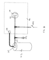
Figure 1 , ahazard control system 100 for controlling a hazard according to various aspects of the present invention may comprise acontrol material source 101 for providing a control material, for example an extinguishant for extinguishing a fire. Thehazard control system 100 may further comprise a hazard detection system 105 for detecting one or more hazards, such a smoke detector, radiation detector, thermal sensor, or gas sensor. Thehazard control system 100 further comprises adelivery system 107, such as anozzle 108 coupled to thevessel 102, to deliver the control material to ahazard area 106 in response to the hazard detection system 105. - The
hazard area 106 is an area that may experience a hazard to be controlled by thehazard control system 100. For example, thehazard area 106 may comprise the interior of a cabinet, device, vehicle, enclosure, and/or other area. Alternatively, the hazard area may comprise an open area that may be affected by thehazard control system 100. - The control material source may comprise any appropriate source of control material, such as a storage facility containing a control material. Referring to
Figure 2 , the source of control material may comprise avessel 102 configured to store a control material for controlling a hazard. The control material may configured to neutralize or combat one or more hazards, such as a fire extinguishant or acid neutralizer. Thevessel 102 may comprise any suitable system for storing and/or providing the control material, such as a tank, pressurized bottle, reservoir, or other container. Thevessel 102 may be configured to withstand various operating conditions. Thevessel 102 may comprise various materials, shapes, dimensions, and coatings according to any appropriate criteria, such as corrosion, cost, deformation, fracture, and/or the like. - The
vessel 102 and the control material may be adapted according the particular hazard and/or environment. For example, if thehazard control system 100 is configured to control ahazard area 106 such that thehazard area 106 maintains a low oxygen level, thevessel 102 may be configured to provide a control material which absorbs or dilutes oxygen levels when transmitted into thehazard area 106. As another example, if thehazard control system 100 is configured to control ahazard area 106 such that equipment withinhazard area 106 is substantially protected from thermal radiation, thevessel 102 may be configured to provide an extinguishant which absorbs thermal radiation when transmitted into thehazard area 106. - The
delivery system 107 is configured to deliver the control material to thehazard area 106. Thedelivery system 107 may comprise any appropriate system for delivering the control material. In the present embodiment, thedelivery system 107 may include anozzle 108 connected to thevessel 102 and disposed in or adjacent to thehazard area 106 such that control material exiting thenozzle 108 is deposited in thehazard area 106. For example, if a fire is detected in thehazard area 106, a fire extinguishant is transmitted from thevessel 102 through thenozzle 108 to thehazard area 106 to extinguish the fire. - The
nozzle 108 may be connected directly or indirectly to thevessel 102 to deliver the control material. For example, thenozzle 108 may be indirectly connected to thevessel 102 via adeployment valve 103, which controls deployment of the control material through thenozzle 108. Thedeployment valve 103 controls whether and, if desired, the amount or type of control material delivered through thenozzle 108. Thedeployment valve 103 may comprise any appropriate mechanism for selectively providing the control material for deployment via thenozzle 108, such as a ball cock, a ball valve, a bibcock, a blast valve, a butterfly valve, a check valve, a double check valve, an electromechanical diaphragm, an electromechanical screw, an electromechanical switch, a freeze valve, a gate valve, a globe valve, a hydraulic valve, a leaf valve, a non-return valve, a pilot valve, a piston valve, a plug valve, a pneumatic valve, a Presta valve, a rotary valve, a Shrader valve, a solenoid valve, and/or the like. In the present embodiment, thedeployment valve 103 responds to a signal, for example a pneumatic signal from the hazard detection system 105, and controls delivery of the extinguishant via thenozzle 108 accordingly. - The hazard detection system 105 generates a hazard signal in response to a detected hazard. The hazard detection system 105 may comprise any appropriate system for detecting one or more specific hazards and generating a corresponding signal, such as system for detecting smoke, heat, poison, radiation, and the like. In the present embodiment, the hazard detection system 105 is configured to detect a fire and provide a corresponding signal to the
deployment valve 103. The hazard signal may comprise any appropriate signal for transmitting relevant information, such as an electrical pulse or signal, acoustic signal, mechanical signal, wireless signal, pneumatic signal, and the like. In the present embodiment, the hazard signal comprises a pneumatic signal generated in response to detection of the hazard condition and provided to thedeployment valve 103, which delivers the extinguishant in response to the signal. The hazard detection system 105 may generate the hazard signal in any suitable manner, for example in conjunction with conventional hazard, such as a smoke detector, fusible link, infrared detector, radiation detector, or other suitable sensor. The hazard detection system 105 detects one or more hazards and generates (or terminates) a corresponding signal. - In the present embodiment, the hazard detection system 105 includes a
pressure tube 104 configured to generate a signal in response to a change in pressure in thepressure tube 104. The hazard detection system further comprises a hazard detector, such as afire detector 110, configured to release the pressure in thepressure tube 104 upon detecting a hazard condition, via avalve 112 connected to thepressure tube 104. - In the present embodiment, the hazard detection system 105 generates the pneumatic signal by changing pressure in the
pressure tube 104, such as by releasing the pressure in the pressure tube 144. Thepressure tube 104 may operate with a higher or lower internal pressure than ambient pressure. Equalizing the internal pressure with the ambient pressure generates the pneumatic hazard signal. The internal pressure may be achieved and sustained in any suitable manner, for example by pressurizing and sealing the pressure tube, connecting the tube to an independent pressure source such as a compressor or pressure bottle, or connecting thepressure tube 104 to thevessel 102 having a pressurized fluid. Any fluid that may be configured to transmit a change in pressure within thepressure tube 104 may be used. For example, a substantially incompressible fluid such as a water-based fluid may be sensitive to changes in temperature and/or changes in the internal volume of thepressure tube 104 sufficient to signal coupled devices in response to a change in pressure. As another example, a substantially inert fluid such as air, nitrogen, or argon may be sensitive to changes in temperature and/or changes in the internal volume of thepressure tube 104 sufficient to signal coupled devices in response to a change in pressure. Thepressure tube 104 may comprise appropriate materials, including Firetrace™ detection tubing, aluminum, aluminum alloy, cement, ceramic, copper, copper alloy, composites, iron, iron alloy, nickel, nickel alloy, organic materials, polymer, titanium, titanium alloy, rubber, and/or the like. Thepressure tube 104 may be configured according to any appropriate shapes, dimensions, materials, and coatings according to desired design considerations such as corrosion, cost, deformation, fracture, combinations, and/or the like. - The pressure changes within the
pressure tube 104 may occur based on any cause or condition. For example, the pressure in the tube may change in response to a release of pressure in thepressure tube 104, for example due to actuation of thepressure control valve 112. Alternatively, pressure changes may be caused by changes in the temperature or volume of the fluid in thepressure tube 104, for example in response to actuation of thepressure control valve 112 or a heat transfer system. In the present embodiment, changes in tube pressure may be induced by multiple mechanisms. For example, thepressure tube 104 may be configured to degrade and leak in response to a hazard condition, such as puncture, rupture, deformation, exposure to fire-induced heat, corrosion, radiation, acoustic pressure, changed ambient pressure, particular solids or fluids, mechanical changes such as a change in the tensile properties or configuration of a coupled sacrificial element, and/or the like. Upon degradation, thepressure tube 104 loses pressure, thus generating the pneumatic signal. - In addition, the hazard detection system 105 may include external systems configured to activate the
hazard control system 100. Various hazards produce various hazard conditions, which may be detected by the hazard detection system 105. For example, fires produce heat and smoke, which may be detected by thefire detector 110, causing thefire detector 110 to activate delivery of the control material. - In the present embodiment, other systems may control the pressure in the
pressure tube 104, such as via thepressure control valve 112. For example, thepressure control valve 112 may be configured to affect pressure within thepressure tube 104 in response to signals from another element, such as thefire detector 110. The affected pressure may be achieved by configuring thevalve 112 to selectively change the pressure within thepressure tube 104, substantially equalize the pressure within thepressure tube 104 to outside thepressure tube 104, change the temperature of the fluid within thepressure tube 104, and/or the like. In the present embodiment, thefire detector 110 opens thepressure control valve 112 upon detecting a fire, thus allowing the pressure in thepressure tube 104 to escape and generate the pneumatic signal. - The
pressure control valve 112 may comprise any suitable mechanism for controlling the pressure in thepressure tube 104, such as a ball cock, a ball valve, a bibcock, a blast valve, a butterfly valve, a check valve, a double check valve, an electromechanical diaphragm, an electromechanical screw, an electromechanical switch, a freeze valve, a gate valve, a globe valve, a hydraulic valve, a leaf valve, a non-return valve, a pilot valve, a piston valve, a plug valve, a pneumatic valve, a Presta valve, a rotary valve, a Shrader valve, a solenoid valve, and/or the like. In the present embodiment, thepressure control valve 112 comprises an electromechanical system coupled to a power source, for example a landline power source, a battery, and/or the like. In the present embodiment, thepressure control valve 112 comprises a solenoid configured for operation at between about 12 and 24 volts. Thepressure control valve 112 may be configured to achieve various changes in pressure within thepressure tube 104 by varying the choice of materials, dimensions, power consumption, and/or the like. - The
pressure control valve 112 may be controlled by any suitable systems to change the pressure in thepressure tube 104 in response to a trigger event. For example, the hazard detection system 105 may be configured to detect various hazardous conditions that may constitute trigger events. In the present embodiment, thefire detector 110 may detect conditions associated with fires. Thefire detector 110 may be replaced or supplemented with detectors of other hazards, such as sensors sensitive to incidence with selected substances, radiation levels and/or frequencies, pressures, acoustic pressures, temperatures, tensile properties of a coupled sacrificial element, and/or the like. Thefire detector 110 suitably comprises a conventional electronic system for fire detection, such as an ionization detector, a mass spectrometer, an optical detector, and/or the like. Thefire detector 110 receives power from one or more sources, such as a landline power connection, a battery, and/or the like. - The hazard detection system 105 may control the
pressure control valve 112 via any suitable signals, such as electrical signals transmitted via a wire, radio waves, magnetic signals as by an electromagnet, mechanical interaction, infrared signals, acoustic signals, and/or the like. In the present embodiment, thefire detector 110 andpressure control valve 112 are configured such that, upon detection of a fire condition, thefire detector 110 transmits an electrical signal to thepressure control valve 112, which responds by changing the pressure within thepressure tube 104, in particular by opening thepressure control valve 112 to release the pressure. - The
fire detector 110,pressure tube 104, and/or other elements of the hazard detection system 105 may be configured for any variety of fire or other hazard conditions. For example, the hazard detection system 105 may monitor for a single hazard condition, such as heat. In this configuration, thepressure tube 104 andfire detector 110 serve as substantially independent detection systems of the same hazard condition. Alternatively, the hazard may be associated with multiple hazard conditions, such as heat and smoke, in which case different detectors may monitor different conditions. In this configuration, thepressure tube 104 andfire detector 110 provide hazard control based on a multiple possible hazard conditions. In addition, thepressure tube 104 andfire detector 110 may be configured to provide hazard detection in response to partially coextensive hazard conditions. In this configuration, thepressure tube 104 andfire detector 110 would provide substantially independent detection systems for some hazard conditions and hazard control based on a variety of input hazard conditions for other hazard conditions. Given the multiplicity of combinations of fire conditions, these examples are illustrative rather than exhaustive. - The
fire detector 110 and thepressure control valve 112 may be configured in any suitable manner to facilitate communication and/or deployment. For example, in one embodiment, thefire detector 110 may include a wireless transmitter and thepressure control valve 112 may include a wireless receiver to receive wireless control signals from thefire detector 110, which facilitates remote placement of thefire detector 110 relative to thepressure control valve 112. Alternatively, thefire detector 110,pressure control valve 112, and/or other elements of the hazard detection system may be connected by hardwire connections, infrared signals, acoustic signals, and the like. - Referring to
Figure 3 , thefire detector 110 andpressure control valve 112 may be at least partially disposed within ahousing 400 to form a single unit. Thehousing 400 may be configured to facilitate installation and power supply to thefire detector 110 and thepressure control valve 112. For example, thehousing 400 may include an area for housing thefire detector 110, such as a conventional housing having slots or other exposure permitting thefire detector 110 to sense the ambient atmosphere. Thehousing 400 may further include an area for thepressure control valve 112, which may be connected to thefire detector 110 to receive signals from thefire detector 110. - The
housing 400 may further be configured to substantially accommodate a portion of thepressure tube 104 to facilitate control of the pressure in thepressure tube 104 by thepressure control valve 112. For example, thehousing 400 may include one or more apertures through which the end of thepressure tube 104 may be connected to thepressure control valve 112. Thehousing 400 may comprise various materials including aluminum, aluminum alloy, cement, ceramic, copper, copper alloy, composites, iron, iron alloy, nickel, nickel alloy, organic materials, polymer, titanium, titanium alloy, and/or the like. Thehousing 400 may comprise various shapes, dimensions, and coatings according to various design considerations such as corrosion, cost, deformation, fracture, and/or the like. Thehousing 400 may be configured to include emissive properties with respect to ambient conditions and these properties may be achieved by including vents, holes, slats, permeable membranes, semi-permeable membranes, selectively permeable membranes, and/or the like within at least a portion of thehousing 400. Further, thehousing 400 may be disassembled intomultiple sections 400A-C to facilitate installation and/or maintenance. - In addition, the
housing 400 may be configured to provide power to the elements of the system, such as thefire detector 110 and thepressure control valve 112. The power source may comprise any appropriates forms and source of power for the various elements. For example, the power source may include a main power source and a backup power source. In one embodiment, the main power source comprises a connection for receiving power from a conventional distribution outlet. The backup power source is configured to provide power in the event of a failure of the main power source, and may comprise any suitable source of power, such as one or more capacitors, batteries, uninterruptible power supplies, generators, solar cells, and/or the like. In the present embodiment, the backup power source includes twobatteries housing 400. Thefirst battery 402 provides backup power to thefire detector 110 and thesecond battery 404 provides backup power to thepressure control valve 112. In one embodiment, thepressure control valve 112 requires a higher power, more expensive, and/or less reliable battery than thefire detector 110. Thus, thevalve battery 404 may fail without disabling the backup power for thefire detector 110 supplied by thefire detector battery 402. - Referring again to
Figure 1 , thehazard control system 100 may be further configured to operate autonomously or in conjunction with external systems, for example a firesystem control unit 109 for a building or the like. The operation with the external systems may be configured in any suitable manner, for example to initiate an alarm, control the operation of thehazard control system 100, automatically notify emergency services, and/or the like. For example, thehazard control system 100 may include a communication interface connected to a remote control unit to signal thecontrol unit 109 in response to a detected fire condition. Thehazard control system 100 may be configured to respond to signals from theremote control unit 109, for example to provide status indicators for thehazard control system 100 and/or remotely activate thehazard control system 100. - The
hazard control system 100 may further comprise additional elements for controlling and activating the hazard control system. For example, the hazard control system may include a manual system for manually activating the hazard control system. Referring again toFigure 2 , in the present embodiment, thehazard control system 100 includes amanual valve 202 configured for manually activating thehazard control system 100. For example, themanual valve 202 may be coupled to thepressure tube 104 such that themanual valve 202 may release the internal pressure of thepressure tube 104. Themanual valve 202 may be operated in any suitable manner, such as manual manipulation of the valve or in conjunction with an actuator, such as motor or the like. - The
manual valve 202 may be located in any suitable location, such as substantially outside of thehazard area 106 or within thehazard area 106. Themanual valve 202 may be coupled to thevessel 102,pressure tube 104,pressure control valve 112, and/or the like. For example, themanual valve 202 may be configured for operation with thevessel 102 such that actuation of themanual valve 202 directs extinguishant to thenozzle 108. Themanual valve 202 may be configured for operation with thepressure tube 104 such that actuation of themanual valve 202 causes a change in pressure within thepressure tube 104 sufficient to direct extinguishant to thenozzle 108. Themanual valve 202 may further be configured for operation with thepressure control valve 112 such that actuation of themanual valve 202 causes actuation of thepressure control valve 112, causing a change in pressure within thepressure tube 104 sufficient to direct extinguishant to thenozzle 108. - The
hazard control system 100 may further comprise systems for providing additional responses in the event of a hazard being detected such that thehazard control system 100 may initiate further responses in addition to delivering the extinguishant in the event that a hazard is detected. Thehazard control system 100 may be configured to prompt any appropriate response, such as alerting emergency personnel, sealing off an area from unauthorized personnel, terminating or initiating ventilation of an area, deactivating hazardous machinery, and/or the like. For example, thehazard control system 100 may comprise a supplementary pressure switch 302. The supplementary pressure switch 302 may facilitate transmitting information relating to changes in pressure within thepressure tube 104 to external systems, such as be generating an electrical signal, mechanical signal, and/or other suitable signal in response to a pressure change within the coupledpressure tube 104. - In one embodiment, the supplementary pressure switch 302 may be coupled to machinery in the vicinity of the
hazard area 106 to cut power or fuel supply to the machinery in the event that the supplementary pressure switch 302 produces a signal indicating a hazard condition as detected by thehazard control system 100. - In other embodiments, the
hazard control system 100 may be configured withmultiple vessels 102,pressure tubes 104,nozzles 108,pressure control valves 112,hazard detectors 110,manual valves 202, and/or supplementary pressure switches 302. For example, the hazard control system may be configured to includemultiple vessels 102 coupled to asingle nozzle 108 andhazard detector 110, such as if controlling thehazard area 106 includes drawing multiple types of extinguishant which cannot be stored together, or if the extinguishing anticipated hazards may require different extinguishants to be applied at different times. As another example, thehazard control system 100 may be configured to include more than onepressure tube 104 coupled to asingle nozzle 108 andhazard detector 110, for example to provide multiple paths for delivering the extinguishant, or to draw different extinguishants in response to different fire conditions. Given the multiplicity of combinations of elements, these examples are illustrative rather than exhaustive. - Referring to
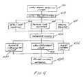
Figure 4 , in operation, thehazard control system 100 is initially configured such that the hazard detection system 105 may sense relevant indicators of hazard conditions (410). For example, thepressure tube 104 may be exposed to the interior of a room or other enclosure so that in the event of a fire, thepressure tube 104 is exposed to heat from the fire. Likewise, relevant sensors, such as thefire detector 110, may be positioned to sense relevant phenomena should a hazard occur. Thedelivery system 107 is also suitably configured to deliver a control material to areas where a hazard may occur (412). - When a hazard occurs, the hazard detection system may detect the hazard and activate the
hazard control system 100. For example, the heat of a fire may degrade the pressure tube 104 (414), causing the interior pressure of thepressure tube 104 to be released, thus generating a pneumatic signal (420). In addition, a sensor, such as a smoke detector, may sense smoke or another relevant hazard indicator (416) and activate thehazard control system 100. For example, the sensor may open thepressure control valve 112, likewise releasing the pressure in thepressure tube 104 and generating the pneumatic signal. Further, the signal may be generated by other systems, such as an external system or the manual valve 202 (418). - The signal is received by the deployment valve, which opens (422) in response to the signal to deliver the control material. The control material is dispensed through the delivery system into the area of the hazard (424), thus tending to control the hazard. The signal may also be received and/or transmitted to other systems, such as the control unit (426) and/or the supplementary pressure switch 302 (428).
- These and other embodiments for methods of controlling a hazard may incorporate concepts, embodiments, and configurations as described with respect to embodiments of apparatus for controlling a hazard as described above. The particular implementations shown and described are illustrative of the invention and its best mode and are not intended to otherwise limit the scope of the present invention in any way. Indeed, for the sake of brevity, conventional manufacturing, connection, preparation, and other functional aspects of the system may not be described in detail. Furthermore, the connecting lines shown in the various figures are intended to represent exemplary functional relationships and/or physical couplings between the various elements. Many alternative or additional functional relationships or physical connections may be present in a practical system.
- The invention has been described with reference to specific exemplary embodiments. The description and figures are to be regarded in an illustrative manner, rather than a restrictive one. Accordingly, the scope of the invention should be determined by the generic embodiments described and their legal equivalents rather than by merely the specific examples described above. For example, the steps recited in any method or process embodiment may be executed in any order, unless otherwise expressly specified, and are not limited to the explicit order presented in the specific examples. Additionally, the components and/or elements recited in any apparatus embodiment may be assembled or otherwise operationally configured in a variety of permutations to produce substantially the same result as the present invention and are accordingly not limited to the specific configuration recited in the specific examples.
- Benefits, other advantages and solutions to problems have been described above with regard to particular embodiments; however, any benefit, advantage, solution to problems or any element that may cause any particular benefit, advantage or solution to occur or to become more pronounced are not to be construed as critical, required or essential features or components.
- As used herein, the terms "comprises", "comprising", or any variation thereof, are intended to reference a non-exclusive inclusion, such that a process, method, article, composition or apparatus that comprises a list of elements does not include only those elements recited, but may also include other elements not expressly listed or inherent to such process, method, article, composition or apparatus. Other combinations and/or modifications of the above-described structures, arrangements, applications, proportions, elements, materials or components used in the practice of the present invention, in addition to those not specifically recited, may be varied or otherwise particularly adapted to specific environments, manufacturing specifications, design parameters or other operating requirements without departing from the general principles of the same.
- The present invention has been described above with reference to a preferred embodiment. However, changes and modifications may be made to the preferred embodiment. These and other changes or modifications are intended to be included within the scope of the present invention, as expressed in the following claims.
Claims (13)
- A combination of a fire control system and an independent fire detector, the fire control system coupled to the independent fire detector (110), wherein the fire control system is configured to deliver an extinguishant in response to a pneumatic signal, the fire control system comprising:a pressure tube (104) having an internal pressure, wherein at least a portion of the pressure tube (104) is configured to leak in response to exposure to heat, wherein the leak changes the internal pressure and generates the pneumatic signal; anda valve (112) coupled to the independent fire detector (110) and the pressure tube (104), wherein the valve (112) is configured to change the internal pressure and generate the pneumatic signal (420) in response to a signal from the independent fire detector (110).
- A combination according to claim 1, further comprising a manually-operated valve (202) coupled to the pressure tube (104).
- A combination according to claim 1 or 2, further comprising a housing (400), wherein the housing (400) contains at least a portion of the independent fire detector (110) and the valve (112).
- A combination according to claim 3, wherein the housing (400) at least partially contains:a power supply connection connected to the independent fire detector (110),a first battery (402) connected to the independent fire detector (110); anda second battery (404) connected to the valve (112).
- A combination according to claim 3 or 4, wherein:the housing (400) has a hole defined therethrough; andthe pressure tube (104) is disposed through the hole to couple to the valve.
- A combination according to any of claims 1 to 5, further comprising a switch (302) coupled to the pressure tube (104), wherein the switch (302) is further configured to generate an electrical signal in response to a change in the internal pressure of the pressure tube (104).
- A combination according to any of claims 1 to 6, further comprising:a vessel (102) configured to store an extinguishant;a nozzle (108) coupled to the vessel and the pressure tube (104), wherein the nozzle (108) is configured to selectively transmit the extinguishant in response to a change in the internal pressure of the pressure tube (104),wherein at least a portion of the pressure tube (104) is configured to leak in response to exposure to a selected temperature; andwherein the valve (112) is configured to change the internal pressure in the pressure tube (104) in response to a signal from the independent fire detector (110).
- A method for forming a fire control system coupled to an independent fire detector (110), comprising:providing a vessel (102) configured to store an extinguishant;providing a pressure tube (104) configured to operate having an internal pressure, wherein at least a portion of the pressure tube (124) is configured to leak in response to a first fire condition;coupling a nozzle (108) to the vessel (102) and the pressure tube (104), wherein the nozzle (108) is configured to selectively transmit the extinguishant in response to a change in the internal pressure of the pressure tube (104), andcoupling a valve (112) to the independent fire detector (110) and the pressure tube (104), wherein the valve (112) is configured to change the internal pressure in the pressure tube (104), in response to a signal from the independent fire detector (104).
- A method according to claim 8, further comprising coupling a manually-operated valve (202) coupled to the pressure tube (104).
- A method according to claim 8 or 9, further comprising providing a housing (400), wherein the housing (400) contains at least a portion of the independent fire detector (110) and the valve (112).
- A method according to claim 10, wherein the housing (400) at least partially contains:a power supply connection connected to the independent fire detector,a first battery (402) connected to the independent fire detector (110), anda second battery (404) connected to the valve (104).
- A method according to any of claims 8 to 11, further comprising coupling a switch (302) to the pressure tube (104), wherein the switch (302) is further configured to generate a signal in response to a change in the internal pressure of the pressure tube (104).
- A method according to any of claims 10 to 12, wherein the housing (400) has a hole defined therethrough, and further comprising:disposing the pressure tube (104) through the hole; andcoupling the pressure tube (104) to the valve (112).
Priority Applications (1)
| Application Number | Priority Date | Filing Date | Title |
|---|---|---|---|
| EP11192338.9A EP2428253B1 (en) | 2007-07-13 | 2008-07-11 | Methods and apparatus for hazard control |
Applications Claiming Priority (2)
| Application Number | Priority Date | Filing Date | Title |
|---|---|---|---|
| US94958607P | 2007-07-13 | 2007-07-13 | |
| PCT/US2008/069871 WO2009012179A1 (en) | 2007-07-13 | 2008-07-11 | Methods and apparatus for hazard control |
Related Child Applications (2)
| Application Number | Title | Priority Date | Filing Date |
|---|---|---|---|
| EP11192338.9A Division EP2428253B1 (en) | 2007-07-13 | 2008-07-11 | Methods and apparatus for hazard control |
| EP11192338.9 Division-Into | 2011-12-07 |
Publications (3)
| Publication Number | Publication Date |
|---|---|
| EP2167198A1 EP2167198A1 (en) | 2010-03-31 |
| EP2167198A4 EP2167198A4 (en) | 2010-08-11 |
| EP2167198B1 true EP2167198B1 (en) | 2012-01-11 |
Family
ID=40260010
Family Applications (2)
| Application Number | Title | Priority Date | Filing Date |
|---|---|---|---|
| EP08772530A Not-in-force EP2167198B1 (en) | 2007-07-13 | 2008-07-11 | Methods and apparatus for hazard control |
| EP11192338.9A Not-in-force EP2428253B1 (en) | 2007-07-13 | 2008-07-11 | Methods and apparatus for hazard control |
Family Applications After (1)
| Application Number | Title | Priority Date | Filing Date |
|---|---|---|---|
| EP11192338.9A Not-in-force EP2428253B1 (en) | 2007-07-13 | 2008-07-11 | Methods and apparatus for hazard control |
Country Status (9)
| Country | Link |
|---|---|
| US (2) | US7823650B2 (en) |
| EP (2) | EP2167198B1 (en) |
| JP (2) | JP5356379B2 (en) |
| KR (1) | KR101426115B1 (en) |
| AT (1) | ATE540728T1 (en) |
| AU (1) | AU2008276205B2 (en) |
| CA (1) | CA2693414C (en) |
| ES (2) | ES2557403T3 (en) |
| WO (1) | WO2009012179A1 (en) |
Families Citing this family (27)
| Publication number | Priority date | Publication date | Assignee | Title |
|---|---|---|---|---|
| US8459369B2 (en) * | 2007-07-13 | 2013-06-11 | Firetrace Usa, Llc | Methods and apparatus for hazard control and signaling |
| US8505642B2 (en) * | 2009-11-05 | 2013-08-13 | Firetrace Usa, Llc | Methods and apparatus for dual stage hazard control system |
| DE102010028857B4 (en) * | 2010-05-11 | 2012-03-22 | Fiwarec Valves & Regulators Gmbh & Co. Kg | Automatic fire extinguishing system |
| US8646540B2 (en) * | 2010-07-20 | 2014-02-11 | Firetrace Usa, Llc | Methods and apparatus for passive non-electrical dual stage fire suppression |
| DE102010035525B4 (en) * | 2010-08-25 | 2012-06-14 | Minimax Gmbh & Co. Kg | Device for extinguishing fires |
| US8863856B2 (en) * | 2011-02-09 | 2014-10-21 | Firetrace Usa, Llc | Methods and apparatus for multi-stage fire suppression |
| US9358411B2 (en) | 2011-05-27 | 2016-06-07 | Victaulic Company | Flexible dry sprinkler |
| DK2714282T3 (en) | 2011-05-27 | 2023-11-20 | Victaulic Co Of America | X-Suspended valve and flexible connection for fire sprinklers |
| EP2722077B1 (en) * | 2012-10-17 | 2019-08-14 | Fogmaker International AB | Fire detection system |
| US9415250B2 (en) | 2012-12-20 | 2016-08-16 | Victaulic Company | Dry sprinkler |
| US10449402B2 (en) | 2012-12-20 | 2019-10-22 | Victaulic Company | Dry sprinkler |
| US9345918B2 (en) | 2012-12-20 | 2016-05-24 | Victaulic Company | Dry sprinkler |
| EP2959946B1 (en) * | 2014-06-27 | 2019-04-24 | Fogmaker International AB | Fire extinguishing system |
| US9393452B2 (en) * | 2014-07-29 | 2016-07-19 | Dan Swift | Anechoic chamber fire suppression system |
| US9884212B2 (en) * | 2014-07-29 | 2018-02-06 | Dan Swift | Anechoic chamber fire suppression system |
| CN105582634A (en) * | 2014-10-20 | 2016-05-18 | 全龙浩 | Temperature sensing tube system capable of repeatedly opening/closing work |
| EP3328507A1 (en) | 2015-07-28 | 2018-06-06 | Globe Fire Sprinkler Corporation | Preaction sprinkler valve assemblies, related dry sprinkler devices and fire protection sprinkler systems |
| US10646736B2 (en) | 2015-07-28 | 2020-05-12 | Victaulic Company | Preaction sprinkler valve assemblies, related dry sprinkler devices adapted for long travel, and fire protection sprinkler systems |
| US20170120089A1 (en) * | 2015-10-30 | 2017-05-04 | Firetrace Usa, Llc | Methods and apparatus for fire suppression system for transportable container |
| SG11201809945PA (en) | 2016-05-10 | 2018-12-28 | Fike Corp | Intelligent temperature and pressure gauge assembly |
| US10850144B2 (en) | 2017-06-14 | 2020-12-01 | Victaulic Company | Preaction sprinkler valve assemblies, related dry sprinkler devices, and compressive activation mechanism |
| US11045675B2 (en) | 2018-02-02 | 2021-06-29 | Victaulic Company | Belleville seal for valve seat having a tear drop laminar flow feature |
| CN110538405A (en) * | 2019-09-29 | 2019-12-06 | 安徽芯核防务装备技术股份有限公司 | novel fire detection and fire extinguishing device |
| CN113941105B (en) * | 2020-07-16 | 2023-12-19 | 哲弗智能系统(上海)有限公司 | Intelligent thermal triggering fire extinguishing device, method, battery pack, energy storage system and vehicle |
| TW202218713A (en) | 2020-10-29 | 2022-05-16 | 美商科慕Fc有限責任公司 | Thermal protection of lithium ion batteries |
| TW202239046A (en) | 2021-03-19 | 2022-10-01 | 美商科慕Fc有限責任公司 | Thermal protection of lithium ion batteries |
| TW202239047A (en) | 2021-03-19 | 2022-10-01 | 美商科慕Fc有限責任公司 | Thermal protection of lithium ion batteries |
Family Cites Families (19)
| Publication number | Priority date | Publication date | Assignee | Title |
|---|---|---|---|---|
| US4356868A (en) * | 1980-07-30 | 1982-11-02 | Ransburg Corporation | Fire-extinguishant system |
| JPS5937562B2 (en) * | 1983-04-27 | 1984-09-11 | 靖通 伯耆 | Transformer fire extinguishing system |
| JPS6037349U (en) * | 1983-08-22 | 1985-03-14 | ホーチキ株式会社 | Dry foam fire extinguishing equipment |
| DE3506152A1 (en) * | 1985-02-22 | 1986-08-28 | Festo KG, 7300 Esslingen | MONITORING DEVICE IN THE FORM OF A PNEUMATIC CIRCUIT ARRANGEMENT |
| US4650003A (en) * | 1985-04-10 | 1987-03-17 | Systecon Inc. | Light path heat detector |
| US5315292A (en) * | 1993-01-11 | 1994-05-24 | Prior Mitchell K | Ceiling mountable smoke detector and fire extinguisher combination |
| JP3697618B2 (en) * | 1995-02-17 | 2005-09-21 | 能美防災株式会社 | Engine room fire extinguisher |
| DE19530355C1 (en) * | 1995-08-18 | 1997-04-03 | Juergen Haro | Stationary fire-fighting device for spraying extinguishing medium on object |
| US5954138A (en) * | 1996-03-20 | 1999-09-21 | Ceodeux-Fire Extinguisher Valves Technology S.A. | Fire extinguisher valve and fire-extinguishing equipment |
| JP3238879B2 (en) * | 1997-03-18 | 2001-12-17 | ホーチキ株式会社 | Fire detection and extinguishing system |
| US6079502A (en) * | 1998-11-06 | 2000-06-27 | Lucent Technologies Inc. | Process station fire suppression system |
| DE19945856B4 (en) * | 1999-09-24 | 2005-12-29 | Robert Bosch Gmbh | Sprinkler device with a valve for extinguishing liquid |
| US6708771B2 (en) * | 2000-03-27 | 2004-03-23 | Victaulic Company Of America | Low pressure electro-pneumatic and gate actuator |
| JP4210821B2 (en) * | 2001-03-30 | 2009-01-21 | 能美防災株式会社 | Sprinkler fire extinguishing equipment |
| US6648077B2 (en) * | 2001-07-12 | 2003-11-18 | Bryan K. Hoffman | Fire extinguishing system |
| JP2003290383A (en) * | 2002-03-29 | 2003-10-14 | Nohmi Bosai Ltd | Package type automatic fire extinguishing equipment |
| US6952169B1 (en) * | 2002-10-22 | 2005-10-04 | Adrian Simtion | Cordless/wireless automatic detection and suppression system |
| JP4140832B2 (en) * | 2003-06-13 | 2008-08-27 | 千住スプリンクラー株式会社 | Sprinkler head |
| KR20040027534A (en) * | 2004-02-10 | 2004-04-01 | 정재묵 | Linear Fire Tube and Non-Power Automatic Fire System |
-
2008
- 2008-07-11 WO PCT/US2008/069871 patent/WO2009012179A1/en active Application Filing
- 2008-07-11 ES ES11192338.9T patent/ES2557403T3/en active Active
- 2008-07-11 AT AT08772530T patent/ATE540728T1/en active
- 2008-07-11 AU AU2008276205A patent/AU2008276205B2/en not_active Ceased
- 2008-07-11 EP EP08772530A patent/EP2167198B1/en not_active Not-in-force
- 2008-07-11 KR KR1020107003030A patent/KR101426115B1/en not_active IP Right Cessation
- 2008-07-11 ES ES08772530T patent/ES2379134T3/en active Active
- 2008-07-11 JP JP2010516286A patent/JP5356379B2/en not_active Expired - Fee Related
- 2008-07-11 CA CA2693414A patent/CA2693414C/en not_active Expired - Fee Related
- 2008-07-11 EP EP11192338.9A patent/EP2428253B1/en not_active Not-in-force
- 2008-07-11 US US12/172,148 patent/US7823650B2/en active Active
-
2010
- 2010-09-24 US US12/890,321 patent/US8087468B2/en active Active
-
2011
- 2011-08-16 JP JP2011177952A patent/JP5373012B2/en not_active Expired - Fee Related
Also Published As
| Publication number | Publication date |
|---|---|
| EP2167198A4 (en) | 2010-08-11 |
| JP2012038322A (en) | 2012-02-23 |
| ATE540728T1 (en) | 2012-01-15 |
| EP2428253A1 (en) | 2012-03-14 |
| ES2557403T3 (en) | 2016-01-25 |
| JP5356379B2 (en) | 2013-12-04 |
| WO2009012179A1 (en) | 2009-01-22 |
| ES2379134T3 (en) | 2012-04-23 |
| US7823650B2 (en) | 2010-11-02 |
| JP5373012B2 (en) | 2013-12-18 |
| EP2428253B1 (en) | 2015-10-14 |
| US8087468B2 (en) | 2012-01-03 |
| KR20100032930A (en) | 2010-03-26 |
| CA2693414C (en) | 2015-12-29 |
| CA2693414A1 (en) | 2009-01-22 |
| EP2167198A1 (en) | 2010-03-31 |
| US20110011600A1 (en) | 2011-01-20 |
| JP2010533907A (en) | 2010-10-28 |
| AU2008276205B2 (en) | 2012-04-12 |
| KR101426115B1 (en) | 2014-08-05 |
| US20090178813A1 (en) | 2009-07-16 |
| AU2008276205A1 (en) | 2009-01-22 |
Similar Documents
| Publication | Publication Date | Title |
|---|---|---|
| EP2167198B1 (en) | Methods and apparatus for hazard control | |
| CA2812266C (en) | Methods and apparatus for hazard control and signaling | |
| KR20170097155A (en) | Alarm valve station of a fire extinguishing system, in particular a sprinkler or spray water extinguishing system, and fire extinguishing system | |
| US9656107B2 (en) | Trigger unit for extinguishing devices | |
| EP2595709A1 (en) | Methods and apparatus for passive non-electrical dual stage fire suppresion | |
| ZA201006565B (en) | Fire suppression system | |
| AU2011204975B2 (en) | Methods and apparatus for hazard control | |
| KR101890892B1 (en) | Automatic valves with multi-actuators for fire extinguishing systems | |
| GB2083353A (en) | Fluid pressure controlled time delay apparatus | |
| GB2562527A (en) | A venting valve assembly for a fluid storage vessel |
Legal Events
| Date | Code | Title | Description |
|---|---|---|---|
| PUAI | Public reference made under article 153(3) epc to a published international application that has entered the european phase |
Free format text: ORIGINAL CODE: 0009012 |
|
| 17P | Request for examination filed |
Effective date: 20100128 |
|
| AK | Designated contracting states |
Kind code of ref document: A1 Designated state(s): AT BE BG CH CY CZ DE DK EE ES FI FR GB GR HR HU IE IS IT LI LT LU LV MC MT NL NO PL PT RO SE SI SK TR |
|
| AX | Request for extension of the european patent |
Extension state: AL BA MK RS |
|
| A4 | Supplementary search report drawn up and despatched |
Effective date: 20100712 |
|
| DAX | Request for extension of the european patent (deleted) | ||
| RIC1 | Information provided on ipc code assigned before grant |
Ipc: A62C 35/02 20060101AFI20110418BHEP |
|
| GRAP | Despatch of communication of intention to grant a patent |
Free format text: ORIGINAL CODE: EPIDOSNIGR1 |
|
| GRAS | Grant fee paid |
Free format text: ORIGINAL CODE: EPIDOSNIGR3 |
|
| GRAA | (expected) grant |
Free format text: ORIGINAL CODE: 0009210 |
|
| AK | Designated contracting states |
Kind code of ref document: B1 Designated state(s): AT BE BG CH CY CZ DE DK EE ES FI FR GB GR HR HU IE IS IT LI LT LU LV MC MT NL NO PL PT RO SE SI SK TR |
|
| REG | Reference to a national code |
Ref country code: GB Ref legal event code: FG4D |
|
| REG | Reference to a national code |
Ref country code: CH Ref legal event code: EP |
|
| REG | Reference to a national code |
Ref country code: AT Ref legal event code: REF Ref document number: 540728 Country of ref document: AT Kind code of ref document: T Effective date: 20120115 |
|
| REG | Reference to a national code |
Ref country code: IE Ref legal event code: FG4D |
|
| REG | Reference to a national code |
Ref country code: DE Ref legal event code: R096 Ref document number: 602008012700 Country of ref document: DE Effective date: 20120315 |
|
| REG | Reference to a national code |
Ref country code: NL Ref legal event code: T3 |
|
| REG | Reference to a national code |
Ref country code: ES Ref legal event code: FG2A Ref document number: 2379134 Country of ref document: ES Kind code of ref document: T3 Effective date: 20120423 |
|
| PG25 | Lapsed in a contracting state [announced via postgrant information from national office to epo] |
Ref country code: SI Free format text: LAPSE BECAUSE OF FAILURE TO SUBMIT A TRANSLATION OF THE DESCRIPTION OR TO PAY THE FEE WITHIN THE PRESCRIBED TIME-LIMIT Effective date: 20120111 |
|
| LTIE | Lt: invalidation of european patent or patent extension |
Effective date: 20120111 |
|
| PG25 | Lapsed in a contracting state [announced via postgrant information from national office to epo] |
Ref country code: BG Free format text: LAPSE BECAUSE OF FAILURE TO SUBMIT A TRANSLATION OF THE DESCRIPTION OR TO PAY THE FEE WITHIN THE PRESCRIBED TIME-LIMIT Effective date: 20120411 Ref country code: IS Free format text: LAPSE BECAUSE OF FAILURE TO SUBMIT A TRANSLATION OF THE DESCRIPTION OR TO PAY THE FEE WITHIN THE PRESCRIBED TIME-LIMIT Effective date: 20120511 Ref country code: NO Free format text: LAPSE BECAUSE OF FAILURE TO SUBMIT A TRANSLATION OF THE DESCRIPTION OR TO PAY THE FEE WITHIN THE PRESCRIBED TIME-LIMIT Effective date: 20120411 Ref country code: LT Free format text: LAPSE BECAUSE OF FAILURE TO SUBMIT A TRANSLATION OF THE DESCRIPTION OR TO PAY THE FEE WITHIN THE PRESCRIBED TIME-LIMIT Effective date: 20120111 Ref country code: HR Free format text: LAPSE BECAUSE OF FAILURE TO SUBMIT A TRANSLATION OF THE DESCRIPTION OR TO PAY THE FEE WITHIN THE PRESCRIBED TIME-LIMIT Effective date: 20120111 |
|
| PG25 | Lapsed in a contracting state [announced via postgrant information from national office to epo] |
Ref country code: FI Free format text: LAPSE BECAUSE OF FAILURE TO SUBMIT A TRANSLATION OF THE DESCRIPTION OR TO PAY THE FEE WITHIN THE PRESCRIBED TIME-LIMIT Effective date: 20120111 Ref country code: PL Free format text: LAPSE BECAUSE OF FAILURE TO SUBMIT A TRANSLATION OF THE DESCRIPTION OR TO PAY THE FEE WITHIN THE PRESCRIBED TIME-LIMIT Effective date: 20120111 Ref country code: GR Free format text: LAPSE BECAUSE OF FAILURE TO SUBMIT A TRANSLATION OF THE DESCRIPTION OR TO PAY THE FEE WITHIN THE PRESCRIBED TIME-LIMIT Effective date: 20120412 Ref country code: LV Free format text: LAPSE BECAUSE OF FAILURE TO SUBMIT A TRANSLATION OF THE DESCRIPTION OR TO PAY THE FEE WITHIN THE PRESCRIBED TIME-LIMIT Effective date: 20120111 Ref country code: PT Free format text: LAPSE BECAUSE OF FAILURE TO SUBMIT A TRANSLATION OF THE DESCRIPTION OR TO PAY THE FEE WITHIN THE PRESCRIBED TIME-LIMIT Effective date: 20120511 |
|
| REG | Reference to a national code |
Ref country code: AT Ref legal event code: MK05 Ref document number: 540728 Country of ref document: AT Kind code of ref document: T Effective date: 20120111 |
|
| PG25 | Lapsed in a contracting state [announced via postgrant information from national office to epo] |
Ref country code: CY Free format text: LAPSE BECAUSE OF FAILURE TO SUBMIT A TRANSLATION OF THE DESCRIPTION OR TO PAY THE FEE WITHIN THE PRESCRIBED TIME-LIMIT Effective date: 20120111 |
|
| PG25 | Lapsed in a contracting state [announced via postgrant information from national office to epo] |
Ref country code: DK Free format text: LAPSE BECAUSE OF FAILURE TO SUBMIT A TRANSLATION OF THE DESCRIPTION OR TO PAY THE FEE WITHIN THE PRESCRIBED TIME-LIMIT Effective date: 20120111 Ref country code: CZ Free format text: LAPSE BECAUSE OF FAILURE TO SUBMIT A TRANSLATION OF THE DESCRIPTION OR TO PAY THE FEE WITHIN THE PRESCRIBED TIME-LIMIT Effective date: 20120111 Ref country code: RO Free format text: LAPSE BECAUSE OF FAILURE TO SUBMIT A TRANSLATION OF THE DESCRIPTION OR TO PAY THE FEE WITHIN THE PRESCRIBED TIME-LIMIT Effective date: 20120111 Ref country code: EE Free format text: LAPSE BECAUSE OF FAILURE TO SUBMIT A TRANSLATION OF THE DESCRIPTION OR TO PAY THE FEE WITHIN THE PRESCRIBED TIME-LIMIT Effective date: 20120111 Ref country code: SE Free format text: LAPSE BECAUSE OF FAILURE TO SUBMIT A TRANSLATION OF THE DESCRIPTION OR TO PAY THE FEE WITHIN THE PRESCRIBED TIME-LIMIT Effective date: 20120111 |
|
| PLBE | No opposition filed within time limit |
Free format text: ORIGINAL CODE: 0009261 |
|
| STAA | Information on the status of an ep patent application or granted ep patent |
Free format text: STATUS: NO OPPOSITION FILED WITHIN TIME LIMIT |
|
| PG25 | Lapsed in a contracting state [announced via postgrant information from national office to epo] |
Ref country code: SK Free format text: LAPSE BECAUSE OF FAILURE TO SUBMIT A TRANSLATION OF THE DESCRIPTION OR TO PAY THE FEE WITHIN THE PRESCRIBED TIME-LIMIT Effective date: 20120111 |
|
| 26N | No opposition filed |
Effective date: 20121012 |
|
| PG25 | Lapsed in a contracting state [announced via postgrant information from national office to epo] |
Ref country code: AT Free format text: LAPSE BECAUSE OF FAILURE TO SUBMIT A TRANSLATION OF THE DESCRIPTION OR TO PAY THE FEE WITHIN THE PRESCRIBED TIME-LIMIT Effective date: 20120111 |
|
| REG | Reference to a national code |
Ref country code: DE Ref legal event code: R097 Ref document number: 602008012700 Country of ref document: DE Effective date: 20121012 |
|
| PG25 | Lapsed in a contracting state [announced via postgrant information from national office to epo] |
Ref country code: MC Free format text: LAPSE BECAUSE OF NON-PAYMENT OF DUE FEES Effective date: 20120731 |
|
| REG | Reference to a national code |
Ref country code: CH Ref legal event code: PL |
|
| PG25 | Lapsed in a contracting state [announced via postgrant information from national office to epo] |
Ref country code: LI Free format text: LAPSE BECAUSE OF NON-PAYMENT OF DUE FEES Effective date: 20120731 Ref country code: CH Free format text: LAPSE BECAUSE OF NON-PAYMENT OF DUE FEES Effective date: 20120731 |
|
| REG | Reference to a national code |
Ref country code: IE Ref legal event code: MM4A |
|
| PG25 | Lapsed in a contracting state [announced via postgrant information from national office to epo] |
Ref country code: IE Free format text: LAPSE BECAUSE OF NON-PAYMENT OF DUE FEES Effective date: 20120711 Ref country code: MT Free format text: LAPSE BECAUSE OF FAILURE TO SUBMIT A TRANSLATION OF THE DESCRIPTION OR TO PAY THE FEE WITHIN THE PRESCRIBED TIME-LIMIT Effective date: 20120111 |
|
| PG25 | Lapsed in a contracting state [announced via postgrant information from national office to epo] |
Ref country code: TR Free format text: LAPSE BECAUSE OF FAILURE TO SUBMIT A TRANSLATION OF THE DESCRIPTION OR TO PAY THE FEE WITHIN THE PRESCRIBED TIME-LIMIT Effective date: 20120111 |
|
| PG25 | Lapsed in a contracting state [announced via postgrant information from national office to epo] |
Ref country code: HU Free format text: LAPSE BECAUSE OF FAILURE TO SUBMIT A TRANSLATION OF THE DESCRIPTION OR TO PAY THE FEE WITHIN THE PRESCRIBED TIME-LIMIT Effective date: 20080711 |
|
| REG | Reference to a national code |
Ref country code: FR Ref legal event code: PLFP Year of fee payment: 9 |
|
| REG | Reference to a national code |
Ref country code: FR Ref legal event code: PLFP Year of fee payment: 10 |
|
| PGFP | Annual fee paid to national office [announced via postgrant information from national office to epo] |
Ref country code: NL Payment date: 20170711 Year of fee payment: 10 Ref country code: LU Payment date: 20170713 Year of fee payment: 10 |
|
| PGFP | Annual fee paid to national office [announced via postgrant information from national office to epo] |
Ref country code: IT Payment date: 20170712 Year of fee payment: 10 Ref country code: DE Payment date: 20170817 Year of fee payment: 10 Ref country code: GB Payment date: 20170822 Year of fee payment: 10 Ref country code: ES Payment date: 20170919 Year of fee payment: 10 Ref country code: FR Payment date: 20170718 Year of fee payment: 10 |
|
| PGFP | Annual fee paid to national office [announced via postgrant information from national office to epo] |
Ref country code: BE Payment date: 20170731 Year of fee payment: 10 |
|
| REG | Reference to a national code |
Ref country code: DE Ref legal event code: R119 Ref document number: 602008012700 Country of ref document: DE |
|
| REG | Reference to a national code |
Ref country code: NL Ref legal event code: MM Effective date: 20180801 |
|
| GBPC | Gb: european patent ceased through non-payment of renewal fee |
Effective date: 20180711 |
|
| PG25 | Lapsed in a contracting state [announced via postgrant information from national office to epo] |
Ref country code: LU Free format text: LAPSE BECAUSE OF NON-PAYMENT OF DUE FEES Effective date: 20180711 |
|
| REG | Reference to a national code |
Ref country code: BE Ref legal event code: MM Effective date: 20180731 |
|
| PG25 | Lapsed in a contracting state [announced via postgrant information from national office to epo] |
Ref country code: GB Free format text: LAPSE BECAUSE OF NON-PAYMENT OF DUE FEES Effective date: 20180711 Ref country code: FR Free format text: LAPSE BECAUSE OF NON-PAYMENT OF DUE FEES Effective date: 20180731 Ref country code: DE Free format text: LAPSE BECAUSE OF NON-PAYMENT OF DUE FEES Effective date: 20190201 |
|
| PG25 | Lapsed in a contracting state [announced via postgrant information from national office to epo] |
Ref country code: NL Free format text: LAPSE BECAUSE OF NON-PAYMENT OF DUE FEES Effective date: 20180801 Ref country code: BE Free format text: LAPSE BECAUSE OF NON-PAYMENT OF DUE FEES Effective date: 20180731 |
|
| PG25 | Lapsed in a contracting state [announced via postgrant information from national office to epo] |
Ref country code: IT Free format text: LAPSE BECAUSE OF NON-PAYMENT OF DUE FEES Effective date: 20180711 |
|
| REG | Reference to a national code |
Ref country code: ES Ref legal event code: FD2A Effective date: 20190917 |
|
| PG25 | Lapsed in a contracting state [announced via postgrant information from national office to epo] |
Ref country code: ES Free format text: LAPSE BECAUSE OF NON-PAYMENT OF DUE FEES Effective date: 20180712 |