EP2160583B1 - Recovery of hidden data embedded in an audio signal and device for data hiding in the compressed domain - Google Patents
Recovery of hidden data embedded in an audio signal and device for data hiding in the compressed domain Download PDFInfo
- Publication number
- EP2160583B1 EP2160583B1 EP08750719A EP08750719A EP2160583B1 EP 2160583 B1 EP2160583 B1 EP 2160583B1 EP 08750719 A EP08750719 A EP 08750719A EP 08750719 A EP08750719 A EP 08750719A EP 2160583 B1 EP2160583 B1 EP 2160583B1
- Authority
- EP
- European Patent Office
- Prior art keywords
- data
- audio
- hidden
- signal
- echoes
- Prior art date
- Legal status (The legal status is an assumption and is not a legal conclusion. Google has not performed a legal analysis and makes no representation as to the accuracy of the status listed.)
- Active
Links
Images


Classifications
-
- G—PHYSICS
- G10—MUSICAL INSTRUMENTS; ACOUSTICS
- G10L—SPEECH ANALYSIS OR SYNTHESIS; SPEECH RECOGNITION; SPEECH OR VOICE PROCESSING; SPEECH OR AUDIO CODING OR DECODING
- G10L19/00—Speech or audio signals analysis-synthesis techniques for redundancy reduction, e.g. in vocoders; Coding or decoding of speech or audio signals, using source filter models or psychoacoustic analysis
- G10L19/018—Audio watermarking, i.e. embedding inaudible data in the audio signal
-
- G—PHYSICS
- G10—MUSICAL INSTRUMENTS; ACOUSTICS
- G10L—SPEECH ANALYSIS OR SYNTHESIS; SPEECH RECOGNITION; SPEECH OR VOICE PROCESSING; SPEECH OR AUDIO CODING OR DECODING
- G10L19/00—Speech or audio signals analysis-synthesis techniques for redundancy reduction, e.g. in vocoders; Coding or decoding of speech or audio signals, using source filter models or psychoacoustic analysis
- G10L19/04—Speech or audio signals analysis-synthesis techniques for redundancy reduction, e.g. in vocoders; Coding or decoding of speech or audio signals, using source filter models or psychoacoustic analysis using predictive techniques
- G10L19/06—Determination or coding of the spectral characteristics, e.g. of the short-term prediction coefficients
-
- G—PHYSICS
- G10—MUSICAL INSTRUMENTS; ACOUSTICS
- G10L—SPEECH ANALYSIS OR SYNTHESIS; SPEECH RECOGNITION; SPEECH OR VOICE PROCESSING; SPEECH OR AUDIO CODING OR DECODING
- G10L19/00—Speech or audio signals analysis-synthesis techniques for redundancy reduction, e.g. in vocoders; Coding or decoding of speech or audio signals, using source filter models or psychoacoustic analysis
- G10L19/04—Speech or audio signals analysis-synthesis techniques for redundancy reduction, e.g. in vocoders; Coding or decoding of speech or audio signals, using source filter models or psychoacoustic analysis using predictive techniques
- G10L19/08—Determination or coding of the excitation function; Determination or coding of the long-term prediction parameters
-
- G—PHYSICS
- G10—MUSICAL INSTRUMENTS; ACOUSTICS
- G10L—SPEECH ANALYSIS OR SYNTHESIS; SPEECH RECOGNITION; SPEECH OR VOICE PROCESSING; SPEECH OR AUDIO CODING OR DECODING
- G10L25/00—Speech or voice analysis techniques not restricted to a single one of groups G10L15/00 - G10L21/00
- G10L25/03—Speech or voice analysis techniques not restricted to a single one of groups G10L15/00 - G10L21/00 characterised by the type of extracted parameters
- G10L25/06—Speech or voice analysis techniques not restricted to a single one of groups G10L15/00 - G10L21/00 characterised by the type of extracted parameters the extracted parameters being correlation coefficients
Landscapes
- Engineering & Computer Science (AREA)
- Physics & Mathematics (AREA)
- Multimedia (AREA)
- Health & Medical Sciences (AREA)
- Audiology, Speech & Language Pathology (AREA)
- Human Computer Interaction (AREA)
- Computational Linguistics (AREA)
- Acoustics & Sound (AREA)
- Signal Processing (AREA)
- Compression, Expansion, Code Conversion, And Decoders (AREA)
- Reverberation, Karaoke And Other Acoustics (AREA)
- Telephonic Communication Services (AREA)
- Traffic Control Systems (AREA)
- Signal Processing Not Specific To The Method Of Recording And Reproducing (AREA)
- Other Investigation Or Analysis Of Materials By Electrical Means (AREA)
Abstract
Description
- This invention relates to a communication system. The invention has particular, but not exclusive relevance to communications systems in which a telephone apparatus such as a cellular telephone is provided with data via an acoustic data channel.
-
WO02/45273 -
EP-A-1503369 discloses a data embedding device for embedding data in a speech code obtained by encoding a speech in accordance with a speech encoding method based on a voice generation process of a human being. The device includes an embedding judgment unit that judges, every speech code, whether or not data should be embedded in the speech code, and an embedding unit that embeds data in two or more parameter codes of a plurality of parameter codes constituting the speech code for which it is judged by the embedding judgment unit that the data should be embedded. The embedded data is then recovered from the speech code by a receiving device before the speech code is decoded to recover the speech. -
US-A-5893067 discloses a method of hiding information in a host audio signal that introduces one or more echoes into the signal. The separation in time between the host signal and an echo is associated with the value of a datum embedded in the signal. The identity of the embedded datum is determined by observing the delay between the host signal and the echo using correlation features in the cepstral domain. - One aim of one embodiment, therefore, is to reduce the processing requirement of the software application.
- The invention provides a method of recovering hidden data from an input audio signal using a telecommunications device having an audio coder for compressing an input audio signal for transmission to a telecommunications network, the method being performed by the telecommunications device and being characterised by passing the input audio signal through the audio coder to generate compressed audio data and processing the compressed audio data to recover the hidden data within the audio signal. The inventors have found that by passing the input audio through the audio coder, the amount of subsequent processing required to recover the hidden data can be significantly reduced. In particular, this processing can be performed without having to regenerate the audio samples and then start with the conventional techniques for recovering the hidden data.
- In one embodiment, the audio coder performs a linear prediction, LP, analysis on the input audio to generate LP data representative of the input audio and wherein the processing step processes the LP data to recover the hidden data or to identify the input audio signal. Preferably, the audio coder compresses the LP data to generate the compressed LP data and the processing step includes the step of regenerating the LP data from the compressed audio data.
- The LP data generated by the coder may include LP filter data, such as LPC filter coefficients, filter poles or line spectral frequencies and the processing step recovers the hidden data using this LP filter data.
- The processing step may include the step of generating an impulse response of the LP synthesis filter or the step of performing a reverse Levinson-Durbin algorithm on the LP filter data. When generating the impulse response, its autocorrelation is preferably taken from which the presence or absence of echoes representing the hidden data can be identified more easily than from the impulse response itself.
- The LP data generated by the audio coder may include LP excitation data (such as codebook indices, excitation pulse positions, pulse signs etc) and the processing step may recover the hidden data using this LP excitation data.
- In most cases, the LP data will include both LP filter data and LP excitation data and the processing step may processes all or a subset of the compressed audio data corresponding to one of said LP filter data and said LP excitation data to recover the hidden data.
- The data can be hidden within the audio signal using a number of techniques. However, in a preferred embodiment, the data is hidden in the audio as one or more echoes of the audio signal. The hidden data can then be recovered by detecting the echoes. Each symbol of the data to be hidden may be represented by a combination of echoes (at the same time) or as a sequence of echoes within the audio signal and the processing step may Include the step of identifying the combinations of echoes to recover the hidden data or the step of tracking the sequence of echoes in the audio to recover the hidden data.
- In one embodiment, the audio coder has a predefined operating frequency band and the echoes are hidden within the audio within a predetermined portion of the operating band, preferably an upper portion of the frequency band, and wherein the processing step includes a filtering step to filter out frequencies outside this predetermined portion. For example, where the audio coder has an operating band of 300Hz to 3.4kHz, the echo may be included only in the band between 1kHz and 3.4kHz and more preferably between 2kHz and 3.4kHz, as this can reduce the effects of the audio signals whose energy typically is located within the lower part of the operating bandwidth. In another embodiment, the echo is included throughout the operating bandwidth but the processing step still performs the filtering, to reduce the effects of the audio. This is not as preferred as part of the echo signal will be lost in the filtering as well.
- In order to help identify the presence of echoes in the audio coder output, the processing step may determine one or more autocorrelation values, which help to highlight the echoes. Inter frame filtering of the autocorrelation values may also be performed to reduce the effects of slowly varying audio components.
- The audio coder used may be any of a number of known coders such as a CELP coder, AMR coder, wideband AMR coder etc.
- In one embodiment, the processing step may determine a spectrograph from the compressed audio data output from the coder and then identify characteristic features (similar to a fingerprint) in the spectrograph. These characteristic features identify the audio input and can be used to determine track information for the audio for output to the user or which can be used to synchronise the telecommunications device to the audio signal, for example outputting subtitles relating to the audio.
- Another embodiment provides telecommunications device comprising: a microphone for receiving acoustic signals and for converting the received acoustic signals into corresponding electrical audio signals; an analog to digital converter for sampling the electrical audio signals to produce digital audio samples; an audio coder for compressing the digital audio samples to generate compressed audio data for transmission to a telecommunications network; and a data processor, coupled to said audio coder, for processing the compressed audio data to recover hidden data conveyed within the received acoustic signal.
- The present invention also provides a data hiding apparatus comprising: audio coding means for receiving and compressing digital audio samples representative of an audio signal to generate compressed audio data; means for receiving data to be hidden within the audio signal; means for hiding the received data in compressed audio data by varying the compressed audio data in dependence upon the received data, to generate modified compressed audio data; and means for generating audio samples using the modified compressed audio data, the audio samples representing the original audio signal and conveying the hidden data by way of one or more echoes.
- These and other aspects of the invention will become apparent from the following detailed description of exemplary embodiments which are described with reference to the accompanying drawings, in which:
-
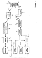
Figure 1 schematically shows a signalling system for communicating data to a cellular telephone via the audio portion of a television signal; -
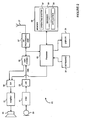
Figure 2 is a schematic block diagram illustrating the main components of a cellular telephone including software applications for recovering data hidden within a received audio signal; -
Figure 3a is a block schematic diagram illustrating the processing performed by an audio codec forming part of the cellular telephone illustrated inFigure 2 ; -
Figure 3b illustrates a source-filter model underlying LP coding of audio signals; -
Figure 3c illustrates the way in which an inverse LPC filter can be used to generate an excitation or residual signal from an input audio signal; -
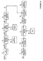
Figure 4 is a schematic block diagram illustrating the processing performed on the output from the audio codec to recover data hidden within the audio signal; -
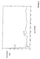
Figure 5 is an autocorrelation plot from which the hidden data can be determined; -
Figure 6 is a block schematic diagram illustrating an alternative processing which can be performed to recover the hidden data; -
Figure 7 is a block schematic diagram illustrating a further alternative way in which the hidden data may be recovered from the output from the audio codec; -
Figure 8 is a block schematic diagram illustrating the way in which hidden data may be recovered from excitation parameters output by the audio codec; -
Figure 9 is an autocorrelation plot output by the autocorrelation section forming part of the circuitry shown inFigure 8 , from which the hidden data can be identified; -
Figure 10 is a block schematic diagram illustrating a refinement to the processing circuitry shown inFigure 4 , in which the impulse response of an LPC synthesis filter is high pass filtered to reduce the effects of low frequency audio components; -
Figure 11 is a block schematic diagram illustrating a further refinement of the processing circuitry shown inFigure 4 in which the LPC coefficients are high pass filtered to remove lower order coefficients relating to lower frequency audio components; -
Figure 12 illustrates a further refinement of the processing circuitry shown inFigure 4 in which the autocorrelation plot illustrated inFigure 5 is high pass filtered to remove slowly varying autocorrelations; -
Figure 13 is a general schematic block diagram illustrating one way in which the hidden data can be encoded within the audio prior to reception by the cellular telephone; -
Figure 14 is a general block diagram illustrating the way in which the cellular telephone recovers the data encoded using the system illustrated inFigure 13 ; -
Figure 15 is a block diagram illustrating one way in which the parameters generated by an LPC coder can be modified and recombined with a residual signal to form the modified audio for transmission to the cellular telephone; and -
Figure 16 illustrates an alternative way in which the excitation parameters obtained from an LPC coder are modified and from which a residual signal is generated for use in synthesising the modified audio with the LPC coefficients obtained from the LPC coder; and -
Figure 17 is a block diagram illustrating the way in which the output of the audio codec can be processed to recover a spectrograph for the input audio for use in identifying or characterising the input audio signal. -
Figure 1 illustrates a first embodiment of the invention in which a data signal F(t), generated by adata source 1, is encoded within an audio track from anaudio source 3 by anencoder 5 to form a modified audio track for a television programme. In this embodiment, the data signal F(t) conveys trigger signals for synchronising the operation of a software application running on a user'smobile telephone 21 with the television programme. As shown inFigure 1 , the modified audio track output by theencoder 5 is then combined with the corresponding video track, from avideo source 7, in asignal generator 9 to form a television signal conveying the television programme. In this embodiment, thedata source 1, theaudio source 3, thevideo source 7 and theencoder 5 are all located in a television studio and the television signal is distributed by adistribution network 11 and, in this embodiment, a radio frequency (RF)signal 13. TheRF signal 13 is received by a television aerial 15 which provides the television signal to aconventional television 17. Thetelevision 17 has a display (not shown) for showing the video track and a loudspeaker not shown for outputting the modified audio track as anacoustic signal 19. - As shown, in this embodiment, the
cellular telephone 21 detects theacoustic signal 19 emitted by thetelevision 17 using amicrophone 23 which converts the detected acoustic signal into a corresponding electrical signal. Thecellular telephone 21 then decodes the electrical signal to recover the data signal F(t). Thecellular telephone 21 also has conventional components such as aloudspeaker 25, anantenna 27 for communicating with acellular base station 35, adisplay 29, akeypad 31 for entering numbers and letters andmenu keys 33 for accessing menu options. The data recovered from the audio signal can be used for a number of different purposes, as explained inWO02/45273 cellular telephone 21 with the television programme being shown on thetelevision 17. For example, there may be a quiz show being shown on thetelevision 17 and thecellular telephone 21 may be arranged to generate and display questions relating to the quiz shown in synchronism with the quiz show. The questions may, for example, be pre-stored on thecellular telephone 21 and output when a suitable synchronisation code is recovered from the data signal F(t). At the end of the quiz show, the answers input by the user into the cellular telephone 21 (via the keypad 31) can then be transmitted to aremote server 41 via the cellulartelephone base station 35 and thetelecommunications network 39. Theserver 41 can then collate the answers received from a large number of users and rank them based on the number of correct answer given and the time taken to input the answers. This timing information could also be determined by thecellular telephone 21 and transmitted to theserver 41 together with the user's answers. As those skilled in the art will appreciate, theserver 41 can also process the information received from the different users and collate various user profile information which it can store in thedatabase 43. This user profile information may then be used, for example, for targeted advertising. - After the
server 41 has identified the one or more "winning" users, information or a prize may be sent to those users. For example, a message may be sent to them over thetelecommunications network 39 together with a coupon or other voucher. As shown by the dashedline 44 inFigure 1 , theserver 41 may also provide thedata source 1 with the data to be encoded within the audio. - As mentioned above, the inventors have realised that the processing required to be carried out by the software running on the
cellular telephone 21 can be reduced by making use of the encoding being performed by the dedicated audio codec chip. In particular, the inventors have found that using the encoding process inherent in the audio codec as an initial step of the decoding process to recover the hidden data, reduces the processing required by the software to recover the hidden data. -
Figure 2 illustrates the main components of thecellular telephone 21 used in this embodiment. As shown, thecellular telephone 21 includes amicrophone 23 for receiving acoustic signals and for converting them into electrical equivalent signals. These electrical signals are then filtered by thefilter 51 to remove unwanted frequencies typically outside the frequency band of 300Hz to 3.4kHz (as defined in standard document EN300-903, published by ETSI). The filtered audio is then digitised by an analog todigital converter 53, which samples the filtered audio at a sampling frequency of 8kHz, representing each sample typically by a 13 to 16 bit digital value. The stream of digitised audio (D(t)) is then input to theaudio codec 55, which is an Adaptive MultiRate (AMR) codec, the operation of which is described below. The compressed audio output by theAMR codec 55 is then passed to anRF processing unit 57 which modulates the compressed audio onto one or more RF carrier signals for transmission to thebase station 35 via theantenna 27. Similarly, compressed audio signals received via theantenna 27 are fed to theRF processing unit 57, which demodulates the received RF signals to recover the compressed audio data from the RF carrier signal(s), which are passed to theAMR codec 55. TheAMR codec 55 then decodes the compressed audio data to regenerate the audio samples represented thereby, which are output to theloudspeaker 25 via the digital toanalog converter 59 and theamplifier 61. - As shown in
Figure 2 , the compressed audio data output from the AMR codec 55 (or the RF processing unit 57) is also passed to theprocessor 63, which is controlled by software stored inmemory 65. The software includes operating system software 67 (for controlling the general operation of the cellular telephone 21), abrowser 68 for accessing the internet andapplication software 69 for providing additional functionality to thecellular telephone 21. In this embodiment, theapplication software 69 is configured to cause thecellular telephone 21 to interact with the television programme in the manner discussed above. To do this, theapplication software 69 is arranged to receive and process the compressed audio data output from theAMR codec 55 to recover the hidden data F(t) which controls theapplication software 69. As will be described in more detail below, the processing of the compressed audio data to recover the hidden data F(t) can be performed without having to regenerate the digitised audio samples and whilst reducing the processing that would have been required by thesoftware application 69 to recover the hidden data directly from the digital audio samples. - In response to recovering the hidden data, the
application software 69 is arranged to generate and output data (eg questions for the user) on thedisplay 29 and to receive the answers input by the user via thekeypad 31. Thesoftware application 69 then transmits the user's answers to the remote server 41 (identified by a pre-stored URL, E.164 number or the like) together with timing data indicative of the time taken by the user to input each answer (calculated by thesoftware application 69 using an internal timer (not shown)). Thesoftware application 69 may also display result information received back from theserver 41 indicative of how well the user did relative to other users who took part in the quiz. - Although the
AMR codec 55 is well known and defined by the 3GPP standards body (in Standards documentation TS 26.090 version 3.1.0), a general description of the processing it performs will now be given with reference toFigure 3 in order that the reader can understand the subsequent description of the processing performed by theapplication software 69. - The AMR codec 55 (Adaptive-Multi-Rate coder-decoder) converts 8 kHz sampled-data audio, in the band 300Hz to 3.4kHz into a stream of bits at a number of different bit-rates. The
codec 55 is therefore highly suited to situations where transmission rates may be required to vary. Its output bit-rate can be adapted to match the prevailing transmission conditions, and for this reason it is a 3G standard and currently used in mostcellular telephones 21. - Although the bit-rate is variable, the same fundamental encoding processes are employed by the
codec 55 at all rates. The quantisation processes, the selection of which parameters are to be transmitted and the rate of transmission are varied to achieve operation in the eight bit-rates or modes: 12.2, 10.2, 7.95, 7.40, 6.70, 5.90, 5.15 and 4.75 Kbits/s. In this embodiment the highest bit-rate mode is used (12.2 Kbits/s). - There are four major component sub-systems in the
AMR codec 55 which are described below. They are: - Pitch prediction
- LPC Analysis
- Fixed codebook lookup
- Adaptive codebook
- The
AMR codec 55 applies them in that order, although for present purposes it is easier to treat pitch prediction last and as part of the adaptive codebook processing. TheAMR codec 55 is built around a CELP (Codebook Excited Linear Prediction) coding system. The input audio signal is divided into 160 sample frames (f) and the frames are subject to linear prediction analysis to extract a small number of coefficients per frame to code and transmit. These coefficients characterise the short-term spectrum of the signal within the frame. In addition to these coefficients, theAMR codec 55 also computes an LPC residual (also referred to as the excitation) which is coded using the adaptive and fixed codebooks assisted by the pitch predictor. These subsystems are described below. - The LPC analysis is performed by the
LPC analysis section 71 shown inFigure 3a . LPC assumes the classical source-filter model of speech production (illustrated inFigure 3b ) in which speech is regarded as the output of a slowly time-varying filter (LPC synthesis filter 72), excited by regular glottal pulses for voiced speech, such as in vowels, and white noise for unvoiced speech, e.g. /sh/, or a mixture of the two for mixed-voice sounds, like /z/ (represented by the excitation block 74). Although based on a model of speech production, it also provides a valid model for encoding all sounds. Thesynthesis filter 72 is assumed to be all-pole, i.e. it has resonances only. This assumption is the basis of the LPC analysis method. In sampled data (z-plane) notation it means that the transfer function is purely a polynomial in Z-1 in the denominator of the transfer function, H(z).
- The time series response sn of this filter to the input excitation en is then:

which says that the output sn of the system is the input, en plus a weighted linear sum of the P previous outputs. This is the theoretical basis of LPC. The limit P is the LPC 'order' which is usually fixed and in the AMR codec 55 P is equal to ten. In the AMR codec 55 (and other LPC based systems) linear prediction analysis is employed to estimate the filter weights or coefficients, ai for each frame of the input audio. Once estimated, they are then converted to a form suitable for quantising and transmission. - Estimating the coefficients ai efficiently requires approximations and assumptions to be made. All methods of solving for the coefficients aim at minimising the contribution of the en in equation (2) above. The
AMR codec 55 uses the autocorrelation method, which means solving P simultaneous linear equations; in matrix form:
- Or in a more abbreviated form:

- The elements, rij of R are the autocorrelation values for the input audio signal at lag |i-j|. As R is symmetric and all elements of each diagonal are equal, it is open to quick recursive methods for finding its inverse. The Levinson-Durbin algorithm is used in the
AMR coder 55. - The coefficients ai are actually not easy to quantise. They change fairly unpredictably with time and have positive and negative values over an undetermined range. The
AMR codec 55 therefore uses aLSF determination section 73 to convert these coefficients to line spectral frequencies before quantising, which removes these disadvantages and allows for the efficient coding of the LPC coefficients. The coefficients ai are the weights of the all-pole synthesis filter 72 and are the coefficients of a Pth order polynomial in z -1, which can be factored to find its roots. These roots are the resonances or poles in thesynthesis filter 72. These poles have often been quantised for transmission as they are reasonably ordered, have average values and change more predictably from frame to frame, which give opportunities for saving bits, which coding the ai does not. Line spectral frequencies (LSFs) are even better for this than the poles. It is important to realise LSFs are not the same as the poles of the all-pole model but they are related. Their derivation is involved, but qualitatively it involves choosing two sets of boundary conditions in a particular representation of the synthesis filter, one boundary condition corresponding to when the glottis is perfectly open and the other corresponding to when the glottis is perfectly closed. This results in two sets of hypothetical poles with zero bandwidth, i.e. perfect resonators. - The main advantages of LSFs are that:
- LSFs consist of a frequency only, their bandwidth is always zero (although there are twice as many LSFs as there are poles)
- LSFs are theoretically better ordered than poles
- LSFs are thus amenable to very low bit-rate coding. In particular, as shown in
Figure 3a , the mean (computed in advance and stored in the data store 75) of each LSF can be subtracted by themean subtraction section 77. Further, as the resulting delta LSF does not change quickly with time; apredictor 79 can then be used to predict the current delta value, which is subtracted from the actual delta by theprediction subtraction section 81. The resulting data are then additionally coded by a vector quantisation (VQ)section 83 which encodes two values at once via a single index, resulting in less than 1-bit per value in some cases. TheAMR codec 55 outputs the VQ index values thus obtained for the current frame as the coded LPC data for transmission to thebase station 35. - As mentioned above, the
AMR codec 55 also encodes theexcitation part 74 of the model illustrated inFigure 3b . In order to do this, theAMP codec 55 generates a representation of the excitation signal so that it can then encode it. As illustrated inFigure 3c , it does this by generating an "inverse"LPC filter 76 which can generate the excitation signal by filtering the input audio signal. The excitation signal obtained from theinverse filter 76 is sometimes also referred to as the residual. Thisinverse LPC filter 76 is actually defined from the same coefficients ai determined above, but using them to define an all-zero model with the transfer function:
- This corresponds in the time-domain to a filter:

- The
inverse LPC filter 76 defined by (6) consists of zeros cancelling out the poles in the all-pole synthesis filter 72 defined by (2). In theory, if the input audio signal is filtered using theinverse filter 76 and then the generated excitation signal is filtered by thesynthesis filter 72, then we arrive back at the input audio signal (hence the name "inverse" LPC filter). It is important to note that the original audio signal need not be speech for a perfect reconstruction to occur. If the LPC analysis has not done a good job in representing the input audio signal, then there will be more information in the residual. - It is the job of the fixed
codebook section 87 and theadaptive codebook section 89 of theAMR codec 55 to code the excitation signal. A relatively large number of bits are used in theAMR codec 55 to code the excitation when compared to the number of bits used for coding the LSFs: 206 out of 244 bits per frame (84%) in 12.2 Kbits/s mode and 72 out of 95 (74%) in 4.75kbits/s mode. It is this use of bits that allows theAMR codec 55 to code non-speech signals with some effect. - The excitation in voiced speech is characterised by a series of clicks (pulses) at the voice pitch (about 100Hz to 130Hz for an adult male in normal speech, twice that for females and children). In unvoiced speech it is white noise (more or less). In mixed speech it is a mixture. One way of thinking about the excitation as the residual is to realise that the LPC analysis takes out the bumps in the audio's short-term spectrum, leaving a residual with a much flatter spectrum. This applies whatever is the input signal.
- In the
AMR codec 55 the excitation signal is coded as the combination of a fixed codebook and an adaptive codebook output. The adaptive codebook does not exist as anything to look up, but is a copy of the previous combinations of the combined codebook outputs fed back at the period predicted by the pitch predictor. - The fixed
codebook section 87 generates the excitation signal (ef) for the current frame by using the LPC coefficients ai output from theLPC analysis section 71 for the current frame, to set the weights of theinverse filter 76 defined in equation (6) above; and by filtering the current frame of the input audio with this filter. The fixed codebook section then identifies the fixed codebook pulses or patterns (stored in the fixed codebook 88) which best cater for new things happening in the excitation signal, which will effectively modify the lagged (delayed) copy of the previous frame's excitation from theadaptive codebook section 89. - Each frame is subdivided into four sub-frames each of which has an independently coded fixed-codebook output. The fixed-codebook excitation for one sub-frame codes the excitation as a series of 5 interleaved trains of pairs of unity amplitude pulses. The possible positions for each pair of pulses are shown in the table below for MR122 (the name of the AMR's 12.2 kb/s mode). As indicated above this coding uses a significant number of bits.
Track Pulse Positions 1 0,5 0, 5, 10, 15, 20, 25, 30, 35 2 1,6 1, 6, 11, 16, 21, 26, 31, 36 3 2, 7 2, 7, 12, 17, 22, 27, 32, 37 4 3,8 3, 8, 13, 19, 23, 28, 33, 38 5 4, 9 4, 9, 14, 19, 24, 29, 34, 39 - The sign of the first pulse in each track is also coded; the sign of the second pulse is the same as the first unless it falls earlier in the track when it is opposite. The gain for the sub frame is also coded.
- The adaptive codebook is a time delayed copy of the previous portion of the combined excitation and is important in coding voiced speech. Because voiced speech is regular, it is possible to code only the difference between the current pitch period and the previous using the fixed codebook output. When added to a saved copy of the previous voice period, we get the estimate of this frame's excitation. The adaptive codebook is not transmitted; the coder and decoder calculate the adaptive codebook from the previous combined output and the current pitch delay.
- The purpose of the pitch predictor (which forms part of the adaptive codebook section 89) is to determine the best delay to use for the adaptive codebook. It is a two stage process. The first is a single pass, open loop pitch prediction that correlates the speech with previous samples to find an estimate of the voiced period if the speech is voiced or the best repetition rate that minimises an error measure. This is followed by a repeated closed-loop prediction to get the best delay for the adaptive codebook within 1/6th of a sample. For this reason pitch prediction is part of the adaptive codebook process in the coder. The calculation is limited by the two stage approach as the second more detailed search only happens over a small number of samples. The
AMR codec 55 uses an analysis by synthesis approach, so selects the best delay by minimising the mean-square-error between outputs and the input speech for candidate delays. - Therefore, to represent the excitation signal for the current frame, the
AMR codec 55 outputs the fixed codebook indices (one for each sub-frame) determined for the current frame, the fixed codebook gain, the adaptive codebook delay and the adaptive codebook gain. It is this data and the LPC encoded data that is made available to theapplication software 69 running on thecellular telephone 21 and from which the hidden data has to be recovered. - There are various ways in which the data F(t) can be hidden within the audio signal and the reader is referred to the paper by Bender entitled "Techniques For Data Hiding", IBM Systems Journal, , for a detailed discussion of different techniques for hiding data in audio. In the present embodiment, the data is hidden in the audio by adding an echo to the audio, with the time delay of the echo being varied to encode the data. This variation may be performed, for example by using a simple no echo corresponds to a binary zero and an echo corresponds to a binary one scheme. Alternatively, a binary one may be represented by the addition of an echo at a first delay and a binary zero may be represented by the addition of an echo at a second different delay. The sign of the echo can also be varied with the data to be hidden. In a more complex encoding scheme a binary one may be represented by a first combination or sequence of echoes (two or more echoes at the same time or applied sequentially) and a binary zero may be represented by a second different combination or sequence of echoes.
- In this embodiment, echoes can be added with delays of 0.75ms and 1.00ms and a binary one is represented by adding an attenuated 0.75ms echo for a first section of the audio (typically corresponding to several AMR frames) followed by adding an attenuated 1.00ms echo in a second section of the audio; and a binary zero is represented by adding an attenuated 1.00ms echo for a first section of the audio followed by adding an attenuated 0.75ms echo in a second section of the audio. Therefore, in order to recover the hidden data, the software application has to process the encoded output from the
AMR codec 55 to identify the sequences of echoes received in the audio and hence the data hidden in the audio. - Typically, echoes are identified in audio signals by performing an autocorrelation of the audio samples and identifying the peaks corresponding to any echoes. However, as mentioned above, the hidden data is to be recovered from the output of the
AMR codec 55. -
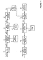
Figure 4 illustrates one way in which the echoes can be detected and the hidden data F(t) recovered by theapplication software 69 from the output of theAMR codec 55. As shown, in this technique, the application software recovers the hidden data solely from the LPC encoded information output by theVQ section 83 shown inFigure 3 . As illustrated inFigure 4 the first processing performed by theapplication software 69 is performed by theVQ section 91, which reverses the vector quantisation performed by theAMR codec 55. The output of theVQ section 91, is then processed by theprediction addition section 93, which adds the LSF delta predictions (determined by the predictor 95) to the outputs from theVQ section 91. The LSF means (obtained from the data store 97) are then added back by themean addition section 99, to recover the LSFs for the current frame. The LSFs are then converted back to the LPC coefficients by theLSF conversion section 101. The thus determined coefficients âi will not be exactly the same as those determined by theLPC analysis section 71 inFigure 3 , due to the approximations and quantisation performed in the other AMR processing stages. - As shown, in this embodiment, the determined LPC coefficients âi are used to configure an
LPC synthesis filter 103 in accordance with equation (2) above. The impulse response (h(n))- of thissynthesis filter 103 is then obtained by applying an impulse (generated by the impulse generator 105) to the thus configuredfilter 103. The inventors have found that the echoes are present within this impulse response (h(n)) and can be found from an autocorrelation of the impulse response around the lags corresponding to the delay of the echo. As shown, theautocorrelation section 107 performs these autocorrelation calculations for the lags identified in thedata store 108.Figure 5 illustrates the autocorrelation obtained for all positive lags. The plot identifies the lags as samples from themain peak 108 at zero lag. So with an 8 kHz sampling rate, each sample corresponds to a lag of 0.125ms. As shown, there is aninitial peak 108 at zero lag, followed by apeak 110 at a lag of about 1.00ms (corresponding to 8 samples from the origin) - indicating that the current frame has a 1.00ms echo. As those skilled in the art will appreciate, there is no need to calculate the autocorrelation for all lags-just those around the lags corresponding to where the echoes are to be found (ie around 0.75ms and 1.00ms). - As shown in
Figure 4 , the autocorrelation values determined by theautocorrelation section 107 are passed to anecho identification section 109, which determines if there are any echoes in the current frame (for example, by thresholding the autocorrelation values with a suitable threshold to identify any peaks at the relevant lags). Identified peaks are then passed to thedata recovery section 111, which tracks the sequence of identified echoes over neighbouring frames to detect the presence of a binary one or a binary zero of the hidden data F(t). In this way, the hidden data is recovered and can then be used to control the operation of theapplication software 69 in the manner described above. - The inventors have found that the computational requirements to recover the hidden data in this way is significantly less than would be required by recovering the hidden data directly from the digitised audio samples.
- In the embodiment described above, the autocorrelation of the LPC synthesis filter's impulse response was determined and from which the presence of the echoes was determined to recover the hidden data.
Figure 6 illustrates the processing that can be performed according to an alternative technique for recovering the hidden data. As can be seen by comparingFigures 4 and6 , the main difference between this embodiment and the first embodiment is that the regenerated LPC coefficients âi for the current frame are directly passed to theautocorrelation section 107, which calculates the autocorrelation of the sequence of LPC coefficients. This embodiment is therefore a simplification of the first embodiment. However, the peaks in the autocorrelation output at the echo lags are not as pronounced as in the first embodiment and so for this reason this simpler embodiment is not preferred where sufficient processing power is available. -
Figure 7 illustrates the processing that can be performed in a third technique for identifying the presence of echoes and the subsequent recovery of the hidden data. As can be seen by comparingFigures 6 and7 , the main difference between this embodiment and the second embodiment is that the regenerated LPC coefficients âi for the current frame are applied to a reverse Levinson-Durbin section 114, which uses the reverse Levinson-Durbin algorithm to re-compute the autocorrelation matrix Rij of equation (3) above from the LPC coefficients. The values determined correspond to the autocorrelation values of the input audio signal itself and will, therefore, include peaks at lags corresponding to the delay of the or each echo. The output from the reverse Levinson-Durbin section 114 can therefore be processed as before, to recover the hidden data. The main disadvantage of this embodiment is that the reverse Levinson-Durbin algorithm is relatively computationally intensive and so where there is limited processing power, this embodiment is not preferred. - In the above three embodiments, the hidden data is recovered by processing the encoded LPC filter data output from the
AMR codec 55. TheAMR codec 55 will encode the echoes in the LPC filter data provided the echo delay is less than the length of the LPC filter. As mentioned above, the LPC filter has an order (P) of ten samples. With an 8kHz sampling frequency, this corresponds to a maximum delay of 1.25ms. If an echo with a longer delay is added, then it can not be encoded into the LPC coefficients. It will, however, be encoded within the residual or excitation signal. To illustrate this, an embodiment will be described in which the binary ones and zeros are encoded in the audio using 2ms and 10ms echoes. -
Figure 8 illustrates the processing performed in this embodiment by theapplication software 69, to recover the hidden data. As shown, in this embodiment, theapplication software 69 receives the excitation encoded data for each frame as it is output by theAMR codec 55. The fixed codebook indices in the received data are used, by the fixedcodebook section 121, to identify the excitation pulses for the current frame from the fixedcodebook 123. These excitation pulses are then amplified by the corresponding fixed gain defined in the encoded data received from theAMR codec 55. The amplified excitation pulses are then applied to anadder 127, where they are added to suitably amplified and delayed versions of previous excitation pulses obtained by passing the previous frame's excitation pulses through thegain 129 and anadaptive codebook delay 131. The adaptive codebook gain and delay used are defined in the encoded data received from theAMR codec 55. The output from theadder 127 is a pulse representation of the residual or excitation signal for the current frame. As shown inFigure 8 , this pulse representation (ei) of the excitation signal is then passed to anautocorrelation section 107 which calculates its autocorrelation for the different lags defined in thelags data store 108.Figure 9 illustrates the autocorrelation output from theautocorrelation section 107 for all positive lags, when there is a 2ms echo in the received audio. As shown, there is amain peak 132 at a zero lag and anotherpeak 134 at a lag corresponding to 2ms. Therefore, the output of theautocorrelation section 107 can be processed as before by theecho identification section 109 and thedata recovery section 111 to recover the hidden data F(t). - A number of refinements to the embodiments described above will now be described with reference to
Figures 10 ,11 and12 . These refinements have been made to increase the successful recovery of the hidden data and aim to combat the effects of speech or room acoustics that can mask the presence of the echoes. These refinements will be applied to the first embodiment described above, but they could equally well be applied to the other embodiments. - As can be seen by comparing
Figures 4 and10 , in the first refinement, the impulse response (h(n)) of theLPC synthesis filter 103 for the current frame is filtered by ahigh pass filter 151 to reduce the effect of the lower frequencies in the impulse response. The inventors have found that the echo information is typically encoded into the higher frequency band of the impulse response. This high pass filtering therefore improves the sharpness of the autocorrelation peaks for the echoes, making it easier to identify their presence. Thehigh pass filter 151 preferably filters out frequencies below about 2kHz (corresponding to a frequency of a quarter of the sampling frequency) although some gain can still be made by filtering out only frequencies below about 1kHz. As those skilled in the art will appreciate, this filtering is an "intra" frame filtering (ie filtering within the frame only) that filters out the low frequency part of the impulse response, although "inter" frame filtering (eg to filter out slowly varying features of the impulse response that occur between frames) could also be performed. -
Figure 11 illustrates an alternative way of achieving the same result. In particular, in this embodiment, the LPC coefficients âi for the current frame are passed through ahigh pass filter 153 before being used to configure theLPC synthesis filter 103. In this case, thehigh pass filter 153 removes the coefficients corresponding to the lower frequency poles of thesynthesis filter 103. This is achieved by factoring the LPC coefficients to identify the pole frequencies and bandwidths. Poles at frequencies below the lower limit are discarded and the remaining poles are used to generate a higher frequency-onlysynthesis filter 103. The remaining processing is as before, and a further description will not be given. As those skilled in the art will appreciate, this filtering is also an intra frame filtering, although inter frame filtering could also be performed. -
Figure 12 illustrates a further refinement that can be applied to increase the success rate of recovering the hidden data. As shown, the main difference between this embodiment and the embodiment shown inFigure 4 is in the provision of ahigh pass filter 155 for performing inter frame filtering to filter out slowly varying correlations (ie correlations that vary slowly from frame to frame) in the autocorrelation output that are typically caused by the audio itself and the acoustics of the room in which the user'scellular telephone 21 is located. In addition to or instead of filtering out such inter frame variations, thehigh pass filter 155 could perform intra frame filtering to remove low frequency correlations from the autocorrelation output within each frame. This has been found to sharpen the correlation peaks caused by the echoes thereby making them easier to identify. - In the above embodiments, data has been hidden within an audio signal by adding echoes having different delays. As those skilled in the art will appreciate, there are various ways in which the data may be hidden within the audio and still be passed through the
AMR codec 55. In general terms, the above data hiding and recovery processes may be represented by the general block diagrams shown inFigures 13 and 14 respectively. As shown inFigure 13 , the general data hiding process can be considered to involve asimilar coding operation 161 to that performed by the AMR codec, to generate the AMR parameters (which may be the final AMR output parameters or intermediate parameters generated in the AMR processing). One or more of these parameters are then varied 163 in dependence upon the data to be hidden within the audio. The modified parameters are then decoded 165 to generate a modified audio signal which is transmitted as an acoustic signal and received by the cellular telephone'smicrophone 23. After filtering and analog to digital conversion, theaudio coder 167 then processes the digitised audio samples in the manner described above to generate the modified parameters. The modified parameters are then processed by theparameter processing section 169 to detect the modification(s) that were made to the parameters and so recover the hidden data. - In the case of adding echoes to the audio to encode the hidden data, this can easily be done in the manner described above without having to perform the detailed encoding process in the television studio (or wherever the data is to be hidden within the audio). Alternatively, the echoes could be added by manipulating the output parameters or intermediate parameters of the AMR coding process. For example, the echoes could be added to the audio by adding a constant to one or more entries of the autocorrelation matrix defined in equation (3) above or by directly manipulating the values of one or more of the LPC coefficients determined from the LPC analysis.
- The data may also be hidden by other more direct ways of modulating the audio coding parameters. For example, the line spectral frequencies generated for the audio may be modified (by for example varying the least significant bit of the LSFs with the data to be hidden), or the frequency or bandwidth of the poles from which the LSFs are determined may be modified in accordance with the data to be hidden. Alternatively still, the excitation parameters may be modified to carry the hidden data. For example, the
AMR codec 55 encodes the excitation signal using fixed and adaptive codebooks which define a train of pulses, with variable pulse positions and signs. Therefore, the data could be hidden by varying the least significant bit of the pulse positions within one or more of the tracks or sub-frames or by changing the sign of selected tracks or sub-frames. - Instead of applying echoes to hide the data in the audio, the phase of one or more frequency components of the audio signal may be varied in dependence upon the data to be hidden. The phase information from the audio is retained to a certain extent in the position of the pulses encoded by the fixed and adaptive codebooks. Therefore, this phase encoding can be detected from the output of the
AMR codec 55 by regenerating the excitation pulses from the codebooks and detecting the phase changes of the relevant frequency component(s) with time. - As those skilled in the art will appreciate, it would be very unlikely that the studio system would use the actual AMR encoder and decoder model, as the audio quality in the television studio will be much greater than that used in the
AMR codec 55. A full studio system would, therefore, split the audio band into an AMR band (between 300Hz and 3.4kHz) and a non-AMR band outside this range. It would then manipulate the AMR band as indicated above, but would not reconstruct the AMR-band signal using the AMR decoder. Instead it would synthesise the AMR band audio signal from the actual LPC residual obtained from the original audio signal and the modified LPC data, to yield higher audio quality. Alternatively, where the excitation parameters are modified with the hidden data, a residual would be constructed from the modified parameters which would then be filtered by the synthesis filter using the LPC coefficients obtained from the LPC analysis. The modified AMR band would then be added to the non-AMR band for transmission as part of the television signal. This processing is illustrated inFigures 15 and 16 . - In particular,
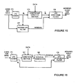
Figure 15 illustrates the processing that may be performed within the television studio after the original audio has been split into the AMR band and the non-AMR band. As shown, the audio AMR band is input to anLPC coder 171 which performs the above-described LPC analysis to generate the LPC coefficients ai for the current frame. These coefficients are then passed to acoefficient variation section 173 which varies one or more of these coefficients in dependence upon the data to be hidden within the audio signal. The modified LPC coefficients âi are then output to configure anLPC synthesis filter 175 in accordance with equation (2) given above. As shown inFigure 15 , the LPC coefficients ai generated by theLPC coder 171 are used to configure aninverse LPC filter 177 in accordance with equation (6) above. The frame of audio from which the current set of LPC coefficients are generated is then passed through this inverse LPC filter to generate the LPC residual (excitation) signal which is then applied to theLPC synthesis filter 175. This results in the generation of a modified audio AMR band signal which is then combined with the non-AMR band signal before being combined with the video track for distribution. -
Figure 16 illustrates the alternative scenario where the excitation parameters are varied with the data to be hidden. In particular, as shown inFigure 16 , the audio AMR band is initially processed by anLPC coder 171, which in this embodiment generates and outputs the fixed and adaptive codebook data representing the residual or excitation signal. This codebook data is then passed through avariation section 181, which varies the codebook data in order to change the position and/or sign of one or more pulses represented by the fixed codebook data in accordance with the data to be hidden within the audio signal. The modified codebook data is then output to aresidual generator 183 which regenerates a corresponding residual signal that will, when processed by theAMR codec 55 regenerate the modified fixed and adaptive codebook data. This may be achieved, for example, by performing an iterative routine to adapt a starting residual until the coding of it results in the modified codebook data output by thevariation section 181. Alternatively, the modified codebook data may be used to generate the pulse trains which are used directly as the residual signal. The gaps between the pulses may be filled with noise or part of the residual signal that can be generated using the inverse LPC filter and the LPC coefficients for the current frame. Regardless of the technique employed, the thus generated residual signal is then passed to theLPC synthesis filter 175 which is configured using the LPC coefficients generated by theLPC coder 171. TheLPC synthesis filter 175 then filters the applied residual signal to generate the modified audio AMR band which is then combined with the non-AMR band to regenerate the audio for combination with the video track. - In the above embodiments, data was hidden within the audio of a television programme and this data was recovered by suitable processing in a cellular telephone. The processing performed to recover the hidden data utilises at least part of the processing that is already carried out by the audio codec of the cellular telephone. As mentioned above, the inventors have found that this reduces the computational overhead required to recover the hidden data. Similar advantages can be obtained in other applications where there is no actual data hidden within the audio but in which, for example, the audio is to be identified from acoustic patterns (fingerprint) of the audio itself. The way in which this can be achieved will now be described with reference to a music identification system.
- At present, there are a number of music identification services, such as the one provided by Shazam. These music identification services allow users of
cellular telephones 21 to identify a music track currently playing by dialling a number and playing the music to the handset. The services then text back the name of the track to the telephone. Technically, the systems operate by setting up a telephone call from the cellular telephone to a remote server whilst playing the music to the telephone. The remote server drops the call after a predetermined period, performs some matching on the received sound against patterns stored in a database to identify the music and then sends a text message to the telephone with the title of the music track it identified. - From published material from the inventors of the Shazam system and others, the general process used to identify tracks is:
- 1. Convert the raw audio signal into a spectrograph, which is usually achieved by calculating a series of overlapping Fast Fourier Transforms (FFTs).
- 2. Analyse the spectrograph to determine characteristic features - these are normally the positions of peaks of energy, characterised by their time and frequency.
- 3. Use a hash function of these features and use the result of the hash function to look up a database to determine a set of entries that may match the audio signal.
- 4. Perform further pattern matching against these potential matches to determine if the audio signal is really a match to any of those indentified from the database.
- Conventionally, the spectrograph for the audio is determined from a series of Fast Fourier Transforms on overlapping blocks of digitised audio samples for the audio signal. When operating over the mobile telephone network, the input audio will be compressed by the AMR codec in the cellular telephone for transmission over the
air interface 37 to themobile telephone network 35, where the compressed audio is decompressed to regenerate the digital audio samples. The server then performs the Fourier Transform analysis on the digital audio samples to generate the spectrograph for the audio signal. - The inventors have realised that this encoding and decoding performed by the mobile telephone system and then the subsequent frequency analysis performed by the Shazam server is wasteful and that a similar system can be implemented without having to decode the compressed audio back to audio samples. In this way, the track recognition processing may be performed entirely within the
cellular telephone 21. The user does not, therefore, have to place a call to a remote server to be able to identify the track that is being played. The way in which this is achieved will now be described with reference toFigure 17 . - In particular,
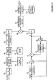
Figure 17 is a block diagram illustrating the processing performed by a track recognition software application (not shown) running on thecellular telephone 21. As shown, in this embodiment, the software application receives the AMR encoded LPC data and the AMR encoded excitation data from theAMR codec 55. The AMR LPC encoded data is then passed to theVQ section 91,prediction addition section 93, meanaddition section 99 andLSF conversion section 101 as before. The result of this processing is the regenerated LPC coefficients âi. The LPC coefficients for the current frame are then passed to anFFT section 201 which calculates their Fast Fourier Transform. - Similarly, the AMR encoded excitation data is decoded by the fixed
codebook section 121, the fixedgain 125, theadder 127, theadaptive codebook delay 121 and theadaptive gain 129, to regenerate the excitation pulses representing the residual for the input frame. These decoded pulses are then input to theFFT section 203 to generate the Fourier transform of the excitation pulses. As shown inFigure 17 , the outputs from the twoFFT sections multiplier 205 to generate a combined frequency representation for the current frame. This combined frequency representation output by themultiplier 205 should correspond approximately to the FFT of the digital audio samples within the current frame. This is because of the source-filter model underlying the LPC analysis performed by theAMR codec 55. In particular, as described above, the LPC analysis assumes that the speech is generated by filtering an appropriate excitation signal through a synthesis filter. In other words, the audio is generated by convolving the excitation signal with the impulse response of the synthesis filter, or in the frequency domain, by multiplying the spectrum of the excitation signal with the spectrum of the LPC synthesis filter. - In the present example, the spectrum of the LPC coefficients is multiplied with the spectrum of the codebook excitation pulses. These are approximations to the spectrum of the LPC synthesis filter and the spectrum of the excitation signal respectively. Therefore, the combined spectrum output from the
multiplier 205 will be an approximation of the spectrum of the digitised audio signal within the current frame. As shown inFigure 17 , this spectrum is then input to aspectrograph generating section 207 which generates a spectrograph from the spectrums received for adjacent frames of the input audio signal. The spectrograph thus generated is then passed to apattern matching section 209 where characteristic features from the spectrograph are used to search patterns stored within apattern database 211 to identify the audio track being picked up by the cellular telephone'smicrophone 23. As those skilled in the art will appreciate, this pattern matching may employ similar processing techniques to those employed in the server of the Shazam system, i.e. using a hash function first to identify a portion of thepattern database 211 to match with the audio's spectrograph. The identified track information output by thepattern matching section 209 is then output for display to the user on thedisplay 29. - The inventors have found that this processing requires significantly less computation than converting the compressed audio data back to digitised audio samples and then taking the Fast Fourier Transform of the audio samples. Indeed, the inventors found that this processing requires less processing than taking the Fast Fourier Transforms of the original audio samples. This is because, taking the Fast Fourier Transform of the LPC coefficients is relatively simple as there are only ten coefficients per frame and because the Fast Fourier Transform of the codebook excitation pulses is also relatively straightforward as the pulse position coefficients can be transformed into the frequency domain simply by differencing the pulse positions or having them precomputed in a look-up table (as there are a limited number of pulse positions defined by the codebook).
- As those skilled in the art will appreciate, the resulting spectrograph obtained in this manner is not directly comparable to that derived from the FFT of the audio samples, due to the approximations that are made. However, the spectrograph carries adequate and similar information to the conventional spectrograph so that the same or similar pattern matching techniques can be used for the audio recognition. For best results, the pattern information stored in the
database 211 is preferably generated from spectrographs obtained in a similar manner (i.e. from the AMR codec output, rather than using those generated directly from the audio samples). - A number of embodiments have been described above illustrating the way in which an audio codec in a cellular telephone may be used to reduce the subsequent processing performed by other parts of the telephone in order to recover hidden information or to identify an input audio segment. As those skilled in the art will appreciate various modifications and improvements can be made to the above embodiments and some of these modifications will now be described.
- In the above audio recognition embodiment, all of the
pattern database 211 was stored within thecellular telephone 21. In an alternative embodiment, thepattern matching section 209 may be arranged to generate a hash function from the characteristic features of the spectrograph generated for the audio and the result of this hash function may then be transmitted to a remote server which downloads the appropriate pattern information to be matched with the audio's spectrograph. In this way the amount of data that has to be stored within thepattern database 211 on thecellular telephone 21 can be kept to a minimum whilst introducing only a relatively small delay in the processing to retrieve selected patterns from the remote database. - In the above audio recognition embodiment, the line spectral frequencies were converted back to LPC coefficients, which were then transformed into the frequency domain using an FFT. In an alternative embodiment, the spectrum for the LPC data may be determined directly from the line spectral frequencies or from the poles derived from them. This would reduce further the processing that is required to perform the audio recognition.
- In the earlier embodiments described above, data was hidden within the audio and used to synchronise the operation of the telephone to a television programme being viewed by the user. In the last embodiment just described, there is no hidden data within the audio and, instead, characteristic features of the audio are indentified and used to recognise the audio. As those skilled in the art will appreciate, similar audio recognition techniques can be used in the synchronisation embodiments. For example, the software application running on the telephone may synchronise itself to the television programme by identifying predetermined portions within the audio soundtrack. This type of synchronising can also be used to control the outputting of subtitles for the television programme.
- In the earlier embodiments described above, the hidden data was recovered by determining autocorrelation values of the LPC coefficients or the impulse response of the synthesis filter. This correlation processing is not essential as the hidden data can be found by monitoring the coefficients or impulse response directly. However, the autocorrelation processing is preferred as it makes it easier to identify the echoes.
- In the refinements described above, various high pass filtering techniques were used to filter out low frequency components associated with the audio and the room acoustics. In a preferred embodiment, where such high pass filtering is performed in the cellular telephone, the echo signal is preferably only added (during the hiding process) to the audio in the high frequency part of the AMR band. For example above 1kHz and preferably above 2kHz only. This can be achieved, for example, by filtering the audio signal to remove the lower frequency AMR band components and then adding the filtered output to the original audio with the required time delay. This is preferred as it reduces the energy in the echo signal that will be filtered out (and therefore lost) by the high pass filtering performed in the cellular telephone.
- In the above embodiments, it has been assumed that the audio codec used by the cellular telephone is the AMR codec. However, as those skilled in the art will appreciate the principles and concepts described above are also applicable to other types of audio codec and especially those that rely on a linear prediction analysis of the input audio.
- In the above embodiments, the various processing of the compressed audio data output from the audio codec has been performed by software running on the cellular telephone. As those skilled in the art will appreciate, some or all of this processing may be formed by dedicated hardware circuits, although software is preferred due to its ability to be added to the cellular telephone after manufacture and its ability to be updated once loaded. The software for causing the cellular telephone to operate in the above manner may be provided as a signal or on a carrier such as compact disc or other carrier medium.
- In the above embodiments, the processing has been performed within a cellular telephone. However, as those skilled in the art will appreciate, the benefits will apply to any communication device which has an inbuilt audio codec.
- In the early embodiments described above, data was hidden within the audio and used to synchronise the operation of the cellular telephone with the television show being watched by the user. As those skilled in the art will appreciate, and as described in
WO02/45273 - In the above embodiment, the television programme was transmitted to the user via an
RF communication link 13. As those skilled in the art will appreciate, the television programme may be distributed to the user via any appropriate distribution technology, such as by cable TV, the Internet, Satellite TV etc. It may also be obtained from a storage medium such as a DVD and read out by an appropriate DVD player. - In the above embodiments, the cellular telephone picked up the audio of a television programme. As those skilled in the art will appreciate, the above techniques can also be used where the audio is obtained from a radio or other loudspeaker system.
- In the above embodiments, it was assumed that the data was hidden within the audio at the television studio end of the television system. In an alternative embodiment, the data may be hidden within the audio at the user's end of the television system, for example, by a set top box. The set top box may be adapted to hide the appropriate data into the audio prior to outputting the television programme to the user.
- In the above embodiments, the software application processed the compressed audio data received from the AMR codec within the
cellular telephone 21. In an alternative embodiment, the software application may perform similar processing on compressed audio data received over the telephone network and provided to theprocessor 63 by theRF processing unit 57. - In the above embodiments, it is assumed that the output of the audio codec does not include the LPC coefficients themselves, but other parameters derived from them, such as the line spectral frequencies or the filter poles of the LPC synthesis filter. As those skilled in the art will appreciate, if the audio codec employed in the
cellular telephone 21 is such that the LPC coefficients derived by it are available to theprocessor 63 then the initial processing performed by the application software to recover the LPC coefficients is not necessary and the software applications can work directly on the LPC coefficients output by the audio codec. This will reduce the required processing further. - As those skilled in the art will appreciate, the precise values of the bit rates, sampling rates etc described in the above embodiments are not essential features of the invention and can be varied without departing from the invention.
Claims (14)
- A method of recovering hidden data from an input audio signal using a telecommunications device (21) having an audio coder (55) for compressing an input audio signal for transmission to a telecommunications network (39), the method being performed by the telecommunications device (21) and being characterised by passing the input audio signal through the audio coder (55) to generate compressed audio data and processing the compressed audio data to recover the hidden data.
- A method according to claim 1, wherein the audio (55) coder performs a linear prediction, LP, analysis on the input audio to generate LP data representative of the input audio and wherein the processing step processes the LP data to recover the hidden data or to identify the input audio signal.
- A method according to claim 2, wherein the audio coder (55) compresses the LP data to generate said compressed LP data and wherein said processing step includes the step of regenerating the LP data from the compressed audio data,
- A method according to claim 2 or 3, wherein the LP data comprises LP filter data and the processing step recovers the hidden data using the LP filter data, and preferably wherein the processing step includes the step of generating an impulse response of a synthesis filter or the step of performing a reverse Levinson-Durbin algorithm on the LP filter data.
- A method according to claim 2 or 3, wherein the LP data comprises LP filter data and LP excitation data and wherein the processing step processes a subset of the compressed audio data corresponding to one of said LP filter data and said LP excitation data to recover the hidden data.
- A method according to any preceding claim, wherein the audio signal includes hidden data defined by one or more echoes of the audio signal and wherein the processing step processes the compressed audio to identify the presence of echoes within the audio signal to recover the hidden data, or wherein each data symbol of the hidden data is represented by a combination of echoes or a sequence of echoes within the audio signal and wherein the processing step includes the step of identifying the combinations of echoes to recover the hidden data or the step of tracking a sequence of echoes in the audio to recover the hidden data.
- A method according to claim 6, wherein the audio coder (55) has a predefined operating frequency band and wherein the echoes are hidden within the audio within a predetermined portion of the operating band, preferably an upper portion of the frequency band, and wherein the processing step includes a filtering step to filter out frequencies outside said predetermined portion.
- A method according to any preceding claim, wherein the processing step determines one or more autocorrelation values for each of a sequence of time frames of the audio signal and recovers the hidden data using the determined autocorrelation values.
- A method according to claim 8, wherein the processing step performs a high pass filtering of the determined autocorrelation values to remove slowly varying correlations.
- A method according to any preceding claim, wherein the processing step recovers the hidden data without regenerating digitised audio samples from the compressed audio data.
- A telecommunications device (21) comprising:a microphone (23) for receiving acoustic signals and for converting the received acoustic signals into corresponding electrical audio signals;an analog to digital converter (53) for sampling the electrical audio signals to produce digital audio samples;an audio coder (55) for compressing the digital audio samples to generate compressed audio data for transmission to a telecommunications network (39); anda data processor (115), coupled to said audio coder (55), for processing the compressed audio data to recover hidden data conveyed within the received acoustic signal.
- A device according to claim 11, adapted to perform the method of any of claims 1 to 10.
- A data hiding apparatus (5) comprising:audio coding means (161) for receiving and compressing digital audio samples representative of an audio signal to generate compressed audio data;means (163) for receiving data to be hidden within the audio signal;means for hiding the received data in compressed audio data by varying the compressed audio data in dependence upon the received data, to generate modified compressed audio data; andmeans (165) for generating audio samples using the modified compressed audio data, the audio samples representing the original audio signal and conveying the hidden data by way of one or more echoes.
- A computer implementable instructions product comprising computer implementable instructions adapted for causing a programmable processor to perform the processing steps of any of claims 1 to 10.
Applications Claiming Priority (2)
| Application Number | Priority Date | Filing Date | Title |
|---|---|---|---|
| GBGB0710211.4A GB0710211D0 (en) | 2007-05-29 | 2007-05-29 | AMR Spectrography |
| PCT/GB2008/001820 WO2008145994A1 (en) | 2007-05-29 | 2008-05-29 | Recovery of hidden data embedded in an audio signal |
Publications (2)
| Publication Number | Publication Date |
|---|---|
| EP2160583A1 EP2160583A1 (en) | 2010-03-10 |
| EP2160583B1 true EP2160583B1 (en) | 2011-09-07 |
Family
ID=38289454
Family Applications (1)
| Application Number | Title | Priority Date | Filing Date |
|---|---|---|---|
| EP08750719A Active EP2160583B1 (en) | 2007-05-29 | 2008-05-29 | Recovery of hidden data embedded in an audio signal and device for data hiding in the compressed domain |
Country Status (8)
| Country | Link |
|---|---|
| US (1) | US20100317396A1 (en) |
| EP (1) | EP2160583B1 (en) |
| JP (1) | JP5226777B2 (en) |
| CN (1) | CN101715549B (en) |
| AT (1) | ATE523878T1 (en) |
| BR (1) | BRPI0812029B1 (en) |
| GB (1) | GB0710211D0 (en) |
| WO (1) | WO2008145994A1 (en) |
Families Citing this family (18)
| Publication number | Priority date | Publication date | Assignee | Title |
|---|---|---|---|---|
| GB2460306B (en) * | 2008-05-29 | 2013-02-13 | Intrasonics Sarl | Data embedding system |
| WO2010138777A1 (en) * | 2009-05-27 | 2010-12-02 | Arsh Technologies, Llc | Automatic resource retrieval and use |
| CN101944360A (en) * | 2009-07-03 | 2011-01-12 | 邱剑 | Method and terminal for convenient use |
| BR122020007866B1 (en) | 2009-10-21 | 2021-06-01 | Dolby International Ab | SYSTEM CONFIGURED TO GENERATE A HIGH FREQUENCY COMPONENT OF AN AUDIO SIGNAL, METHOD FOR GENERATING A HIGH FREQUENCY COMPONENT OF AN AUDIO SIGNAL AND METHOD FOR DESIGNING A HARMONIC TRANSPOSITOR |
| WO2012006171A2 (en) * | 2010-06-29 | 2012-01-12 | Georgia Tech Research Corporation | Systems and methods for detecting call provenance from call audio |
| FR2966635A1 (en) * | 2010-10-20 | 2012-04-27 | France Telecom | Method for displaying e.g. song lyrics of audio content under form of text on e.g. smartphone, involves recognizing voice data of audio content, and displaying recognized voice data in form of text on device |
| US20130053012A1 (en) * | 2011-08-23 | 2013-02-28 | Chinmay S. Dhodapkar | Methods and systems for determining a location based preference metric for a requested parameter |
| WO2013144092A1 (en) * | 2012-03-27 | 2013-10-03 | mr.QR10 GMBH & CO. KG | Apparatus and method for acquiring a data record, data record distribution system, and mobile device |
| CN103377165A (en) * | 2012-04-13 | 2013-10-30 | 鸿富锦精密工业(深圳)有限公司 | Electronic device with USB (universal serial bus) interface |
| GB201206564D0 (en) | 2012-04-13 | 2012-05-30 | Intrasonics Sarl | Event engine synchronisation |
| US9786281B1 (en) * | 2012-08-02 | 2017-10-10 | Amazon Technologies, Inc. | Household agent learning |
| US10419556B2 (en) | 2012-08-11 | 2019-09-17 | Federico Fraccaroli | Method, system and apparatus for interacting with a digital work that is performed in a predetermined location |
| US11184448B2 (en) | 2012-08-11 | 2021-11-23 | Federico Fraccaroli | Method, system and apparatus for interacting with a digital work |
| US9473582B1 (en) | 2012-08-11 | 2016-10-18 | Federico Fraccaroli | Method, system, and apparatus for providing a mediated sensory experience to users positioned in a shared location |
| WO2015068310A1 (en) | 2013-11-11 | 2015-05-14 | 株式会社東芝 | Digital-watermark detection device, method, and program |
| US20160380814A1 (en) * | 2015-06-23 | 2016-12-29 | Roost, Inc. | Systems and methods for provisioning a battery-powered device to access a wireless communications network |
| GB2556023B (en) | 2016-08-15 | 2022-02-09 | Intrasonics Sarl | Audio matching |
| US20230368320A1 (en) * | 2022-05-10 | 2023-11-16 | BizMerlinHR Inc. | Automated detection of employee career pathways |
Citations (1)
| Publication number | Priority date | Publication date | Assignee | Title |
|---|---|---|---|---|
| WO1999035639A1 (en) * | 1998-01-08 | 1999-07-15 | Art-Advanced Recognition Technologies Ltd. | A vocoder-based voice recognizer |
Family Cites Families (17)
| Publication number | Priority date | Publication date | Assignee | Title |
|---|---|---|---|---|
| US5457807A (en) * | 1994-03-21 | 1995-10-10 | Weinblatt; Lee S. | Technique for surveying a radio or a television audience |
| JPH08149163A (en) * | 1994-11-18 | 1996-06-07 | Toshiba Corp | Signal transmitter and receiver and its method |
| US5893067A (en) * | 1996-05-31 | 1999-04-06 | Massachusetts Institute Of Technology | Method and apparatus for echo data hiding in audio signals |
| DE69717505T2 (en) * | 1997-03-21 | 2003-10-02 | Canal & Technologies Paris | METHOD FOR REMOVING DATA IN AN MPEG RECEIVER / DECODER |
| US6125172A (en) * | 1997-04-18 | 2000-09-26 | Lucent Technologies, Inc. | Apparatus and method for initiating a transaction having acoustic data receiver that filters human voice |
| US6467089B1 (en) * | 1997-12-23 | 2002-10-15 | Nielsen Media Research, Inc. | Audience measurement system incorporating a mobile handset |
| ES2296585T3 (en) * | 1998-05-12 | 2008-05-01 | Nielsen Media Research, Inc. | AUDIENCE MEASUREMENT SYSTEM FOR DIGITAL TELEVISION. |
| US7155159B1 (en) * | 2000-03-06 | 2006-12-26 | Lee S. Weinblatt | Audience detection |
| US20010055391A1 (en) * | 2000-04-27 | 2001-12-27 | Jacobs Paul E. | System and method for extracting, decoding, and utilizing hidden data embedded in audio signals |
| GB2365295A (en) * | 2000-07-27 | 2002-02-13 | Cambridge Consultants | Watermarking key |
| US6674876B1 (en) * | 2000-09-14 | 2004-01-06 | Digimarc Corporation | Watermarking in the time-frequency domain |
| CN101282541B (en) * | 2000-11-30 | 2011-04-06 | 因特拉松尼克斯有限公司 | Communication system |
| AU2211102A (en) * | 2000-11-30 | 2002-06-11 | Scient Generics Ltd | Acoustic communication system |
| KR100375822B1 (en) * | 2000-12-18 | 2003-03-15 | 한국전자통신연구원 | Watermark Embedding/Detecting Apparatus and Method for Digital Audio |
| KR20040048978A (en) * | 2001-10-25 | 2004-06-10 | 코닌클리케 필립스 일렉트로닉스 엔.브이. | Method of transmission of wideband audio signals on a transmission channel with reduced bandwidth |
| JP4527369B2 (en) | 2003-07-31 | 2010-08-18 | 富士通株式会社 | Data embedding device and data extraction device |
| CN101115124B (en) * | 2006-07-26 | 2012-04-18 | 日电(中国)有限公司 | Method and apparatus for identifying media program based on audio watermark |
-
2007
- 2007-05-29 GB GBGB0710211.4A patent/GB0710211D0/en not_active Ceased
-
2008
- 2008-05-29 JP JP2010509891A patent/JP5226777B2/en active Active
- 2008-05-29 BR BRPI0812029A patent/BRPI0812029B1/en active IP Right Grant
- 2008-05-29 AT AT08750719T patent/ATE523878T1/en not_active IP Right Cessation
- 2008-05-29 EP EP08750719A patent/EP2160583B1/en active Active
- 2008-05-29 WO PCT/GB2008/001820 patent/WO2008145994A1/en active Application Filing
- 2008-05-29 US US12/601,878 patent/US20100317396A1/en not_active Abandoned
- 2008-05-29 CN CN2008800178789A patent/CN101715549B/en active Active
Patent Citations (1)
| Publication number | Priority date | Publication date | Assignee | Title |
|---|---|---|---|---|
| WO1999035639A1 (en) * | 1998-01-08 | 1999-07-15 | Art-Advanced Recognition Technologies Ltd. | A vocoder-based voice recognizer |
Also Published As
| Publication number | Publication date |
|---|---|
| CN101715549B (en) | 2013-03-06 |
| ATE523878T1 (en) | 2011-09-15 |
| GB0710211D0 (en) | 2007-07-11 |
| EP2160583A1 (en) | 2010-03-10 |
| JP5226777B2 (en) | 2013-07-03 |
| BRPI0812029A2 (en) | 2014-11-18 |
| WO2008145994A1 (en) | 2008-12-04 |
| JP2010530154A (en) | 2010-09-02 |
| CN101715549A (en) | 2010-05-26 |
| BRPI0812029B1 (en) | 2018-11-21 |
| US20100317396A1 (en) | 2010-12-16 |
Similar Documents
| Publication | Publication Date | Title |
|---|---|---|
| EP2160583B1 (en) | Recovery of hidden data embedded in an audio signal and device for data hiding in the compressed domain | |
| US5371853A (en) | Method and system for CELP speech coding and codebook for use therewith | |
| EP0770987B1 (en) | Method and apparatus for reproducing speech signals, method and apparatus for decoding the speech, method and apparatus for synthesizing the speech and portable radio terminal apparatus | |
| US6353808B1 (en) | Apparatus and method for encoding a signal as well as apparatus and method for decoding a signal | |
| US5265190A (en) | CELP vocoder with efficient adaptive codebook search | |
| US20050252361A1 (en) | Sound encoding apparatus and sound encoding method | |
| US20070271101A1 (en) | Audio/Music Decoding Device and Audiomusic Decoding Method | |
| RU2366007C2 (en) | Method and device for speech restoration in system of distributed speech recognition | |
| US20090204397A1 (en) | Linear predictive coding of an audio signal | |
| JP2011123506A (en) | Variable rate speech coding | |
| CA2076072A1 (en) | Auditory model for parametrization of speech | |
| JP2003501675A (en) | Speech synthesis method and speech synthesizer for synthesizing speech from pitch prototype waveform by time-synchronous waveform interpolation | |
| US6141637A (en) | Speech signal encoding and decoding system, speech encoding apparatus, speech decoding apparatus, speech encoding and decoding method, and storage medium storing a program for carrying out the method | |
| US6778953B1 (en) | Method and apparatus for representing masked thresholds in a perceptual audio coder | |
| KR20060083202A (en) | Low bit-rate audio encoding | |
| EP1120775A1 (en) | Noise signal encoder and voice signal encoder | |
| EP1385150B1 (en) | Method and system for parametric characterization of transient audio signals | |
| US7603271B2 (en) | Speech coding apparatus with perceptual weighting and method therefor | |
| JP2004513392A (en) | Audio signal encoding based on sinusoidal model | |
| JP2004302259A (en) | Hierarchical encoding method and hierarchical decoding method for sound signal | |
| JPH09508479A (en) | Burst excitation linear prediction | |
| JP4578145B2 (en) | Speech coding apparatus, speech decoding apparatus, and methods thereof | |
| KR20060064694A (en) | Harmonic noise weighting in digital speech coders | |
| JP2615862B2 (en) | Voice encoding / decoding method and apparatus | |
| EP0987680A1 (en) | Audio signal processing |
Legal Events
| Date | Code | Title | Description |
|---|---|---|---|
| PUAI | Public reference made under article 153(3) epc to a published international application that has entered the european phase |
Free format text: ORIGINAL CODE: 0009012 |
|
| 17P | Request for examination filed |
Effective date: 20091221 |
|
| AK | Designated contracting states |
Kind code of ref document: A1 Designated state(s): AT BE BG CH CY CZ DE DK EE ES FI FR GB GR HR HU IE IS IT LI LT LU LV MC MT NL NO PL PT RO SE SI SK TR |
|
| AX | Request for extension of the european patent |
Extension state: AL BA MK RS |
|
| 17Q | First examination report despatched |
Effective date: 20100422 |
|
| DAX | Request for extension of the european patent (deleted) | ||
| REG | Reference to a national code |
Ref country code: DE Ref legal event code: R079 Ref document number: 602008009591 Country of ref document: DE Free format text: PREVIOUS MAIN CLASS: G01L0019000000 Ipc: G10L0019000000 |
|
| GRAP | Despatch of communication of intention to grant a patent |
Free format text: ORIGINAL CODE: EPIDOSNIGR1 |
|
| RTI1 | Title (correction) |
Free format text: RECOVERY OF HIDDEN DATA EMBEDDED IN AN AUDIO SIGNAL AND DEVICE FOR DATA HIDING IN THE COMPRESSED DOMAIN |
|
| RIC1 | Information provided on ipc code assigned before grant |
Ipc: G10L 19/00 20060101AFI20110203BHEP |
|
| GRAS | Grant fee paid |
Free format text: ORIGINAL CODE: EPIDOSNIGR3 |
|
| GRAA | (expected) grant |
Free format text: ORIGINAL CODE: 0009210 |
|
| RAP1 | Party data changed (applicant data changed or rights of an application transferred) |
Owner name: INTRASONICS S.A.R.L. |
|
| REG | Reference to a national code |
Ref country code: GB Ref legal event code: FG4D |
|
| REG | Reference to a national code |
Ref country code: CH Ref legal event code: EP |
|
| REG | Reference to a national code |
Ref country code: IE Ref legal event code: FG4D |
|
| REG | Reference to a national code |
Ref country code: DE Ref legal event code: R096 Ref document number: 602008009591 Country of ref document: DE Effective date: 20111117 |
|
| REG | Reference to a national code |
Ref country code: NL Ref legal event code: VDEP Effective date: 20110907 |
|
| PG25 | Lapsed in a contracting state [announced via postgrant information from national office to epo] |
Ref country code: HR Free format text: LAPSE BECAUSE OF FAILURE TO SUBMIT A TRANSLATION OF THE DESCRIPTION OR TO PAY THE FEE WITHIN THE PRESCRIBED TIME-LIMIT Effective date: 20110907 Ref country code: NO Free format text: LAPSE BECAUSE OF FAILURE TO SUBMIT A TRANSLATION OF THE DESCRIPTION OR TO PAY THE FEE WITHIN THE PRESCRIBED TIME-LIMIT Effective date: 20111207 Ref country code: SE Free format text: LAPSE BECAUSE OF FAILURE TO SUBMIT A TRANSLATION OF THE DESCRIPTION OR TO PAY THE FEE WITHIN THE PRESCRIBED TIME-LIMIT Effective date: 20110907 Ref country code: LT Free format text: LAPSE BECAUSE OF FAILURE TO SUBMIT A TRANSLATION OF THE DESCRIPTION OR TO PAY THE FEE WITHIN THE PRESCRIBED TIME-LIMIT Effective date: 20110907 Ref country code: FI Free format text: LAPSE BECAUSE OF FAILURE TO SUBMIT A TRANSLATION OF THE DESCRIPTION OR TO PAY THE FEE WITHIN THE PRESCRIBED TIME-LIMIT Effective date: 20110907 |
|
| LTIE | Lt: invalidation of european patent or patent extension |
Effective date: 20110907 |
|
| PG25 | Lapsed in a contracting state [announced via postgrant information from national office to epo] |
Ref country code: AT Free format text: LAPSE BECAUSE OF FAILURE TO SUBMIT A TRANSLATION OF THE DESCRIPTION OR TO PAY THE FEE WITHIN THE PRESCRIBED TIME-LIMIT Effective date: 20110907 Ref country code: CY Free format text: LAPSE BECAUSE OF FAILURE TO SUBMIT A TRANSLATION OF THE DESCRIPTION OR TO PAY THE FEE WITHIN THE PRESCRIBED TIME-LIMIT Effective date: 20110907 Ref country code: SI Free format text: LAPSE BECAUSE OF FAILURE TO SUBMIT A TRANSLATION OF THE DESCRIPTION OR TO PAY THE FEE WITHIN THE PRESCRIBED TIME-LIMIT Effective date: 20110907 Ref country code: GR Free format text: LAPSE BECAUSE OF FAILURE TO SUBMIT A TRANSLATION OF THE DESCRIPTION OR TO PAY THE FEE WITHIN THE PRESCRIBED TIME-LIMIT Effective date: 20111208 Ref country code: LV Free format text: LAPSE BECAUSE OF FAILURE TO SUBMIT A TRANSLATION OF THE DESCRIPTION OR TO PAY THE FEE WITHIN THE PRESCRIBED TIME-LIMIT Effective date: 20110907 |
|
| REG | Reference to a national code |
Ref country code: AT Ref legal event code: MK05 Ref document number: 523878 Country of ref document: AT Kind code of ref document: T Effective date: 20110907 |
|
| PG25 | Lapsed in a contracting state [announced via postgrant information from national office to epo] |
Ref country code: BE Free format text: LAPSE BECAUSE OF FAILURE TO SUBMIT A TRANSLATION OF THE DESCRIPTION OR TO PAY THE FEE WITHIN THE PRESCRIBED TIME-LIMIT Effective date: 20110907 |
|
| PG25 | Lapsed in a contracting state [announced via postgrant information from national office to epo] |
Ref country code: CZ Free format text: LAPSE BECAUSE OF FAILURE TO SUBMIT A TRANSLATION OF THE DESCRIPTION OR TO PAY THE FEE WITHIN THE PRESCRIBED TIME-LIMIT Effective date: 20110907 Ref country code: IS Free format text: LAPSE BECAUSE OF FAILURE TO SUBMIT A TRANSLATION OF THE DESCRIPTION OR TO PAY THE FEE WITHIN THE PRESCRIBED TIME-LIMIT Effective date: 20120107 Ref country code: SK Free format text: LAPSE BECAUSE OF FAILURE TO SUBMIT A TRANSLATION OF THE DESCRIPTION OR TO PAY THE FEE WITHIN THE PRESCRIBED TIME-LIMIT Effective date: 20110907 |
|
| PG25 | Lapsed in a contracting state [announced via postgrant information from national office to epo] |
Ref country code: PL Free format text: LAPSE BECAUSE OF FAILURE TO SUBMIT A TRANSLATION OF THE DESCRIPTION OR TO PAY THE FEE WITHIN THE PRESCRIBED TIME-LIMIT Effective date: 20110907 Ref country code: IT Free format text: LAPSE BECAUSE OF FAILURE TO SUBMIT A TRANSLATION OF THE DESCRIPTION OR TO PAY THE FEE WITHIN THE PRESCRIBED TIME-LIMIT Effective date: 20110907 Ref country code: RO Free format text: LAPSE BECAUSE OF FAILURE TO SUBMIT A TRANSLATION OF THE DESCRIPTION OR TO PAY THE FEE WITHIN THE PRESCRIBED TIME-LIMIT Effective date: 20110907 Ref country code: NL Free format text: LAPSE BECAUSE OF FAILURE TO SUBMIT A TRANSLATION OF THE DESCRIPTION OR TO PAY THE FEE WITHIN THE PRESCRIBED TIME-LIMIT Effective date: 20110907 Ref country code: EE Free format text: LAPSE BECAUSE OF FAILURE TO SUBMIT A TRANSLATION OF THE DESCRIPTION OR TO PAY THE FEE WITHIN THE PRESCRIBED TIME-LIMIT Effective date: 20110907 Ref country code: PT Free format text: LAPSE BECAUSE OF FAILURE TO SUBMIT A TRANSLATION OF THE DESCRIPTION OR TO PAY THE FEE WITHIN THE PRESCRIBED TIME-LIMIT Effective date: 20120109 |
|
| PLBE | No opposition filed within time limit |
Free format text: ORIGINAL CODE: 0009261 |
|
| STAA | Information on the status of an ep patent application or granted ep patent |
Free format text: STATUS: NO OPPOSITION FILED WITHIN TIME LIMIT |
|
| PG25 | Lapsed in a contracting state [announced via postgrant information from national office to epo] |
Ref country code: DK Free format text: LAPSE BECAUSE OF FAILURE TO SUBMIT A TRANSLATION OF THE DESCRIPTION OR TO PAY THE FEE WITHIN THE PRESCRIBED TIME-LIMIT Effective date: 20110907 |
|
| 26N | No opposition filed |
Effective date: 20120611 |
|
| REG | Reference to a national code |
Ref country code: DE Ref legal event code: R097 Ref document number: 602008009591 Country of ref document: DE Effective date: 20120611 |
|
| PG25 | Lapsed in a contracting state [announced via postgrant information from national office to epo] |
Ref country code: MC Free format text: LAPSE BECAUSE OF NON-PAYMENT OF DUE FEES Effective date: 20120531 |
|
| REG | Reference to a national code |
Ref country code: CH Ref legal event code: PL |
|
| PG25 | Lapsed in a contracting state [announced via postgrant information from national office to epo] |
Ref country code: LI Free format text: LAPSE BECAUSE OF NON-PAYMENT OF DUE FEES Effective date: 20120531 Ref country code: CH Free format text: LAPSE BECAUSE OF NON-PAYMENT OF DUE FEES Effective date: 20120531 |
|
| REG | Reference to a national code |
Ref country code: IE Ref legal event code: MM4A |
|
| PG25 | Lapsed in a contracting state [announced via postgrant information from national office to epo] |
Ref country code: IE Free format text: LAPSE BECAUSE OF NON-PAYMENT OF DUE FEES Effective date: 20120529 Ref country code: ES Free format text: LAPSE BECAUSE OF FAILURE TO SUBMIT A TRANSLATION OF THE DESCRIPTION OR TO PAY THE FEE WITHIN THE PRESCRIBED TIME-LIMIT Effective date: 20111218 |
|
| PG25 | Lapsed in a contracting state [announced via postgrant information from national office to epo] |
Ref country code: BG Free format text: LAPSE BECAUSE OF FAILURE TO SUBMIT A TRANSLATION OF THE DESCRIPTION OR TO PAY THE FEE WITHIN THE PRESCRIBED TIME-LIMIT Effective date: 20111207 |
|
| PG25 | Lapsed in a contracting state [announced via postgrant information from national office to epo] |
Ref country code: MT Free format text: LAPSE BECAUSE OF FAILURE TO SUBMIT A TRANSLATION OF THE DESCRIPTION OR TO PAY THE FEE WITHIN THE PRESCRIBED TIME-LIMIT Effective date: 20110907 |
|
| PG25 | Lapsed in a contracting state [announced via postgrant information from national office to epo] |
Ref country code: TR Free format text: LAPSE BECAUSE OF FAILURE TO SUBMIT A TRANSLATION OF THE DESCRIPTION OR TO PAY THE FEE WITHIN THE PRESCRIBED TIME-LIMIT Effective date: 20110907 |
|
| PG25 | Lapsed in a contracting state [announced via postgrant information from national office to epo] |
Ref country code: LU Free format text: LAPSE BECAUSE OF NON-PAYMENT OF DUE FEES Effective date: 20120529 |
|
| PG25 | Lapsed in a contracting state [announced via postgrant information from national office to epo] |
Ref country code: HU Free format text: LAPSE BECAUSE OF FAILURE TO SUBMIT A TRANSLATION OF THE DESCRIPTION OR TO PAY THE FEE WITHIN THE PRESCRIBED TIME-LIMIT Effective date: 20080529 |
|
| REG | Reference to a national code |
Ref country code: FR Ref legal event code: PLFP Year of fee payment: 8 |
|
| REG | Reference to a national code |
Ref country code: FR Ref legal event code: PLFP Year of fee payment: 9 |
|
| REG | Reference to a national code |
Ref country code: FR Ref legal event code: PLFP Year of fee payment: 10 |
|
| REG | Reference to a national code |
Ref country code: FR Ref legal event code: PLFP Year of fee payment: 11 |
|
| P01 | Opt-out of the competence of the unified patent court (upc) registered |
Effective date: 20230515 |
|
| PGFP | Annual fee paid to national office [announced via postgrant information from national office to epo] |
Ref country code: FR Payment date: 20230517 Year of fee payment: 16 Ref country code: DE Payment date: 20230510 Year of fee payment: 16 |
|
| PGFP | Annual fee paid to national office [announced via postgrant information from national office to epo] |
Ref country code: GB Payment date: 20230526 Year of fee payment: 16 |