EP2160168B1 - Apparatus and method for exercise and/or analysis of the locomotor system of a user - Google Patents
Apparatus and method for exercise and/or analysis of the locomotor system of a user Download PDFInfo
- Publication number
- EP2160168B1 EP2160168B1 EP08773588A EP08773588A EP2160168B1 EP 2160168 B1 EP2160168 B1 EP 2160168B1 EP 08773588 A EP08773588 A EP 08773588A EP 08773588 A EP08773588 A EP 08773588A EP 2160168 B1 EP2160168 B1 EP 2160168B1
- Authority
- EP
- European Patent Office
- Prior art keywords
- user
- sensor
- basic element
- excitation function
- evaluation device
- Prior art date
- Legal status (The legal status is an assumption and is not a legal conclusion. Google has not performed a legal analysis and makes no representation as to the accuracy of the status listed.)
- Active
Links
- 238000000034 method Methods 0.000 title claims abstract description 9
- 230000003137 locomotive effect Effects 0.000 title claims abstract 8
- 230000005284 excitation Effects 0.000 claims abstract description 50
- 238000011156 evaluation Methods 0.000 claims abstract description 35
- 230000033001 locomotion Effects 0.000 claims abstract description 25
- 238000005316 response function Methods 0.000 claims abstract description 17
- 230000000737 periodic effect Effects 0.000 claims abstract description 9
- 238000012549 training Methods 0.000 claims description 21
- 230000001133 acceleration Effects 0.000 claims description 4
- 230000005540 biological transmission Effects 0.000 claims description 3
- 210000002346 musculoskeletal system Anatomy 0.000 description 26
- 210000003205 muscle Anatomy 0.000 description 16
- 230000000875 corresponding effect Effects 0.000 description 14
- 230000000638 stimulation Effects 0.000 description 9
- 238000013016 damping Methods 0.000 description 7
- 238000001514 detection method Methods 0.000 description 5
- 230000004044 response Effects 0.000 description 5
- 230000008901 benefit Effects 0.000 description 4
- 210000002683 foot Anatomy 0.000 description 4
- 230000004913 activation Effects 0.000 description 3
- 210000002414 leg Anatomy 0.000 description 3
- 230000009471 action Effects 0.000 description 2
- 238000006243 chemical reaction Methods 0.000 description 2
- 238000010276 construction Methods 0.000 description 2
- 230000008602 contraction Effects 0.000 description 2
- 230000002596 correlated effect Effects 0.000 description 2
- 238000011161 development Methods 0.000 description 2
- 230000018109 developmental process Effects 0.000 description 2
- 210000003127 knee Anatomy 0.000 description 2
- 230000007257 malfunction Effects 0.000 description 2
- 238000012544 monitoring process Methods 0.000 description 2
- 230000004118 muscle contraction Effects 0.000 description 2
- 238000005457 optimization Methods 0.000 description 2
- 230000010355 oscillation Effects 0.000 description 2
- 230000010363 phase shift Effects 0.000 description 2
- 210000000689 upper leg Anatomy 0.000 description 2
- 208000008035 Back Pain Diseases 0.000 description 1
- 230000006978 adaptation Effects 0.000 description 1
- 244000309466 calf Species 0.000 description 1
- 230000001419 dependent effect Effects 0.000 description 1
- 238000013461 design Methods 0.000 description 1
- 238000006073 displacement reaction Methods 0.000 description 1
- 210000003414 extremity Anatomy 0.000 description 1
- 210000004744 fore-foot Anatomy 0.000 description 1
- 230000005484 gravity Effects 0.000 description 1
- 230000009931 harmful effect Effects 0.000 description 1
- 230000006872 improvement Effects 0.000 description 1
- 238000005259 measurement Methods 0.000 description 1
- 230000007246 mechanism Effects 0.000 description 1
- 230000001404 mediated effect Effects 0.000 description 1
- 238000012986 modification Methods 0.000 description 1
- 230000004048 modification Effects 0.000 description 1
- NJPPVKZQTLUDBO-UHFFFAOYSA-N novaluron Chemical compound C1=C(Cl)C(OC(F)(F)C(OC(F)(F)F)F)=CC=C1NC(=O)NC(=O)C1=C(F)C=CC=C1F NJPPVKZQTLUDBO-UHFFFAOYSA-N 0.000 description 1
- 230000001105 regulatory effect Effects 0.000 description 1
- 230000001953 sensory effect Effects 0.000 description 1
- 230000035939 shock Effects 0.000 description 1
- 230000004936 stimulating effect Effects 0.000 description 1
- 230000002123 temporal effect Effects 0.000 description 1
- 230000001225 therapeutic effect Effects 0.000 description 1
- 238000012546 transfer Methods 0.000 description 1
Images


Classifications
-
- A—HUMAN NECESSITIES
- A61—MEDICAL OR VETERINARY SCIENCE; HYGIENE
- A61H—PHYSICAL THERAPY APPARATUS, e.g. DEVICES FOR LOCATING OR STIMULATING REFLEX POINTS IN THE BODY; ARTIFICIAL RESPIRATION; MASSAGE; BATHING DEVICES FOR SPECIAL THERAPEUTIC OR HYGIENIC PURPOSES OR SPECIFIC PARTS OF THE BODY
- A61H1/00—Apparatus for passive exercising; Vibrating apparatus; Chiropractic devices, e.g. body impacting devices, external devices for briefly extending or aligning unbroken bones
- A61H1/001—Apparatus for applying movements to the whole body
- A61H1/003—Rocking or oscillating around a horizontal axis transverse to the body
-
- A—HUMAN NECESSITIES
- A61—MEDICAL OR VETERINARY SCIENCE; HYGIENE
- A61H—PHYSICAL THERAPY APPARATUS, e.g. DEVICES FOR LOCATING OR STIMULATING REFLEX POINTS IN THE BODY; ARTIFICIAL RESPIRATION; MASSAGE; BATHING DEVICES FOR SPECIAL THERAPEUTIC OR HYGIENIC PURPOSES OR SPECIFIC PARTS OF THE BODY
- A61H1/00—Apparatus for passive exercising; Vibrating apparatus; Chiropractic devices, e.g. body impacting devices, external devices for briefly extending or aligning unbroken bones
- A61H1/005—Moveable platforms, e.g. vibrating or oscillating platforms for standing, sitting, laying or leaning
-
- A—HUMAN NECESSITIES
- A63—SPORTS; GAMES; AMUSEMENTS
- A63B—APPARATUS FOR PHYSICAL TRAINING, GYMNASTICS, SWIMMING, CLIMBING, OR FENCING; BALL GAMES; TRAINING EQUIPMENT
- A63B21/00—Exercising apparatus for developing or strengthening the muscles or joints of the body by working against a counterforce, with or without measuring devices
- A63B21/00196—Exercising apparatus for developing or strengthening the muscles or joints of the body by working against a counterforce, with or without measuring devices using pulsed counterforce, e.g. vibrating resistance means
-
- A—HUMAN NECESSITIES
- A63—SPORTS; GAMES; AMUSEMENTS
- A63B—APPARATUS FOR PHYSICAL TRAINING, GYMNASTICS, SWIMMING, CLIMBING, OR FENCING; BALL GAMES; TRAINING EQUIPMENT
- A63B22/00—Exercising apparatus specially adapted for conditioning the cardio-vascular system, for training agility or co-ordination of movements
- A63B22/16—Platforms for rocking motion about a horizontal axis, e.g. axis through the middle of the platform; Balancing drums; Balancing boards or the like
-
- A—HUMAN NECESSITIES
- A63—SPORTS; GAMES; AMUSEMENTS
- A63B—APPARATUS FOR PHYSICAL TRAINING, GYMNASTICS, SWIMMING, CLIMBING, OR FENCING; BALL GAMES; TRAINING EQUIPMENT
- A63B24/00—Electric or electronic controls for exercising apparatus of preceding groups; Controlling or monitoring of exercises, sportive games, training or athletic performances
-
- A—HUMAN NECESSITIES
- A61—MEDICAL OR VETERINARY SCIENCE; HYGIENE
- A61B—DIAGNOSIS; SURGERY; IDENTIFICATION
- A61B5/00—Measuring for diagnostic purposes; Identification of persons
- A61B5/103—Detecting, measuring or recording devices for testing the shape, pattern, colour, size or movement of the body or parts thereof, for diagnostic purposes
- A61B5/107—Measuring physical dimensions, e.g. size of the entire body or parts thereof
- A61B5/1071—Measuring physical dimensions, e.g. size of the entire body or parts thereof measuring angles, e.g. using goniometers
-
- A—HUMAN NECESSITIES
- A61—MEDICAL OR VETERINARY SCIENCE; HYGIENE
- A61B—DIAGNOSIS; SURGERY; IDENTIFICATION
- A61B5/00—Measuring for diagnostic purposes; Identification of persons
- A61B5/103—Detecting, measuring or recording devices for testing the shape, pattern, colour, size or movement of the body or parts thereof, for diagnostic purposes
- A61B5/11—Measuring movement of the entire body or parts thereof, e.g. head or hand tremor, mobility of a limb
-
- A—HUMAN NECESSITIES
- A61—MEDICAL OR VETERINARY SCIENCE; HYGIENE
- A61B—DIAGNOSIS; SURGERY; IDENTIFICATION
- A61B5/00—Measuring for diagnostic purposes; Identification of persons
- A61B5/24—Detecting, measuring or recording bioelectric or biomagnetic signals of the body or parts thereof
- A61B5/316—Modalities, i.e. specific diagnostic methods
- A61B5/389—Electromyography [EMG]
-
- A—HUMAN NECESSITIES
- A61—MEDICAL OR VETERINARY SCIENCE; HYGIENE
- A61H—PHYSICAL THERAPY APPARATUS, e.g. DEVICES FOR LOCATING OR STIMULATING REFLEX POINTS IN THE BODY; ARTIFICIAL RESPIRATION; MASSAGE; BATHING DEVICES FOR SPECIAL THERAPEUTIC OR HYGIENIC PURPOSES OR SPECIFIC PARTS OF THE BODY
- A61H2201/00—Characteristics of apparatus not provided for in the preceding codes
- A61H2201/01—Constructive details
- A61H2201/0119—Support for the device
- A61H2201/0134—Cushion or similar support
-
- A—HUMAN NECESSITIES
- A61—MEDICAL OR VETERINARY SCIENCE; HYGIENE
- A61H—PHYSICAL THERAPY APPARATUS, e.g. DEVICES FOR LOCATING OR STIMULATING REFLEX POINTS IN THE BODY; ARTIFICIAL RESPIRATION; MASSAGE; BATHING DEVICES FOR SPECIAL THERAPEUTIC OR HYGIENIC PURPOSES OR SPECIFIC PARTS OF THE BODY
- A61H2201/00—Characteristics of apparatus not provided for in the preceding codes
- A61H2201/01—Constructive details
- A61H2201/0165—Damping, vibration related features
-
- A—HUMAN NECESSITIES
- A61—MEDICAL OR VETERINARY SCIENCE; HYGIENE
- A61H—PHYSICAL THERAPY APPARATUS, e.g. DEVICES FOR LOCATING OR STIMULATING REFLEX POINTS IN THE BODY; ARTIFICIAL RESPIRATION; MASSAGE; BATHING DEVICES FOR SPECIAL THERAPEUTIC OR HYGIENIC PURPOSES OR SPECIFIC PARTS OF THE BODY
- A61H2201/00—Characteristics of apparatus not provided for in the preceding codes
- A61H2201/12—Driving means
- A61H2201/1207—Driving means with electric or magnetic drive
- A61H2201/1215—Rotary drive
-
- A—HUMAN NECESSITIES
- A61—MEDICAL OR VETERINARY SCIENCE; HYGIENE
- A61H—PHYSICAL THERAPY APPARATUS, e.g. DEVICES FOR LOCATING OR STIMULATING REFLEX POINTS IN THE BODY; ARTIFICIAL RESPIRATION; MASSAGE; BATHING DEVICES FOR SPECIAL THERAPEUTIC OR HYGIENIC PURPOSES OR SPECIFIC PARTS OF THE BODY
- A61H2201/00—Characteristics of apparatus not provided for in the preceding codes
- A61H2201/16—Physical interface with patient
- A61H2201/1602—Physical interface with patient kind of interface, e.g. head rest, knee support or lumbar support
- A61H2201/164—Feet or leg, e.g. pedal
-
- A—HUMAN NECESSITIES
- A61—MEDICAL OR VETERINARY SCIENCE; HYGIENE
- A61H—PHYSICAL THERAPY APPARATUS, e.g. DEVICES FOR LOCATING OR STIMULATING REFLEX POINTS IN THE BODY; ARTIFICIAL RESPIRATION; MASSAGE; BATHING DEVICES FOR SPECIAL THERAPEUTIC OR HYGIENIC PURPOSES OR SPECIFIC PARTS OF THE BODY
- A61H2201/00—Characteristics of apparatus not provided for in the preceding codes
- A61H2201/16—Physical interface with patient
- A61H2201/1657—Movement of interface, i.e. force application means
- A61H2201/1676—Pivoting
- A61H2201/1678—Means for angularly oscillating massage elements
-
- A—HUMAN NECESSITIES
- A61—MEDICAL OR VETERINARY SCIENCE; HYGIENE
- A61H—PHYSICAL THERAPY APPARATUS, e.g. DEVICES FOR LOCATING OR STIMULATING REFLEX POINTS IN THE BODY; ARTIFICIAL RESPIRATION; MASSAGE; BATHING DEVICES FOR SPECIAL THERAPEUTIC OR HYGIENIC PURPOSES OR SPECIFIC PARTS OF THE BODY
- A61H2201/00—Characteristics of apparatus not provided for in the preceding codes
- A61H2201/50—Control means thereof
- A61H2201/5058—Sensors or detectors
- A61H2201/5061—Force sensors
-
- A—HUMAN NECESSITIES
- A61—MEDICAL OR VETERINARY SCIENCE; HYGIENE
- A61H—PHYSICAL THERAPY APPARATUS, e.g. DEVICES FOR LOCATING OR STIMULATING REFLEX POINTS IN THE BODY; ARTIFICIAL RESPIRATION; MASSAGE; BATHING DEVICES FOR SPECIAL THERAPEUTIC OR HYGIENIC PURPOSES OR SPECIFIC PARTS OF THE BODY
- A61H2201/00—Characteristics of apparatus not provided for in the preceding codes
- A61H2201/50—Control means thereof
- A61H2201/5058—Sensors or detectors
- A61H2201/5071—Pressure sensors
-
- A—HUMAN NECESSITIES
- A61—MEDICAL OR VETERINARY SCIENCE; HYGIENE
- A61H—PHYSICAL THERAPY APPARATUS, e.g. DEVICES FOR LOCATING OR STIMULATING REFLEX POINTS IN THE BODY; ARTIFICIAL RESPIRATION; MASSAGE; BATHING DEVICES FOR SPECIAL THERAPEUTIC OR HYGIENIC PURPOSES OR SPECIFIC PARTS OF THE BODY
- A61H23/00—Percussion or vibration massage, e.g. using supersonic vibration; Suction-vibration massage; Massage with moving diaphragms
- A61H23/02—Percussion or vibration massage, e.g. using supersonic vibration; Suction-vibration massage; Massage with moving diaphragms with electric or magnetic drive
- A61H23/0254—Percussion or vibration massage, e.g. using supersonic vibration; Suction-vibration massage; Massage with moving diaphragms with electric or magnetic drive with rotary motor
-
- A—HUMAN NECESSITIES
- A63—SPORTS; GAMES; AMUSEMENTS
- A63B—APPARATUS FOR PHYSICAL TRAINING, GYMNASTICS, SWIMMING, CLIMBING, OR FENCING; BALL GAMES; TRAINING EQUIPMENT
- A63B21/00—Exercising apparatus for developing or strengthening the muscles or joints of the body by working against a counterforce, with or without measuring devices
- A63B21/06—User-manipulated weights
- A63B21/072—Dumb-bells, bar-bells or the like, e.g. weight discs having an integral peripheral handle
- A63B21/0726—Dumb bells, i.e. with a central bar to be held by a single hand, and with weights at the ends
-
- A—HUMAN NECESSITIES
- A63—SPORTS; GAMES; AMUSEMENTS
- A63B—APPARATUS FOR PHYSICAL TRAINING, GYMNASTICS, SWIMMING, CLIMBING, OR FENCING; BALL GAMES; TRAINING EQUIPMENT
- A63B2208/00—Characteristics or parameters related to the user or player
- A63B2208/02—Characteristics or parameters related to the user or player posture
- A63B2208/0204—Standing on the feet
-
- A—HUMAN NECESSITIES
- A63—SPORTS; GAMES; AMUSEMENTS
- A63B—APPARATUS FOR PHYSICAL TRAINING, GYMNASTICS, SWIMMING, CLIMBING, OR FENCING; BALL GAMES; TRAINING EQUIPMENT
- A63B2208/00—Characteristics or parameters related to the user or player
- A63B2208/02—Characteristics or parameters related to the user or player posture
- A63B2208/0285—Hanging
- A63B2208/029—Hanging upright
-
- A—HUMAN NECESSITIES
- A63—SPORTS; GAMES; AMUSEMENTS
- A63B—APPARATUS FOR PHYSICAL TRAINING, GYMNASTICS, SWIMMING, CLIMBING, OR FENCING; BALL GAMES; TRAINING EQUIPMENT
- A63B2220/00—Measuring of physical parameters relating to sporting activity
- A63B2220/10—Positions
- A63B2220/16—Angular positions
-
- A—HUMAN NECESSITIES
- A63—SPORTS; GAMES; AMUSEMENTS
- A63B—APPARATUS FOR PHYSICAL TRAINING, GYMNASTICS, SWIMMING, CLIMBING, OR FENCING; BALL GAMES; TRAINING EQUIPMENT
- A63B2220/00—Measuring of physical parameters relating to sporting activity
- A63B2220/40—Acceleration
-
- A—HUMAN NECESSITIES
- A63—SPORTS; GAMES; AMUSEMENTS
- A63B—APPARATUS FOR PHYSICAL TRAINING, GYMNASTICS, SWIMMING, CLIMBING, OR FENCING; BALL GAMES; TRAINING EQUIPMENT
- A63B2220/00—Measuring of physical parameters relating to sporting activity
- A63B2220/50—Force related parameters
- A63B2220/51—Force
-
- A—HUMAN NECESSITIES
- A63—SPORTS; GAMES; AMUSEMENTS
- A63B—APPARATUS FOR PHYSICAL TRAINING, GYMNASTICS, SWIMMING, CLIMBING, OR FENCING; BALL GAMES; TRAINING EQUIPMENT
- A63B2230/00—Measuring physiological parameters of the user
- A63B2230/08—Measuring physiological parameters of the user other bio-electrical signals
Definitions
- the WO 2006/070429 describes a training device, which in turn is tuned to a predetermined, optimal muscle contraction frequency.
- the method according to the invention provides that the excitation function of the device is detected by means of at least one sensor and in an evaluation device the excitation function generated by the device and also applied to the user is compared with the response function of the user resulting from the excitation function impressed on the user, by the evaluation device analyzed the amplitude and / or the phase angle of these two functions for determining parameters of the musculoskeletal system of the user.
Landscapes
- Health & Medical Sciences (AREA)
- General Health & Medical Sciences (AREA)
- Physical Education & Sports Medicine (AREA)
- Life Sciences & Earth Sciences (AREA)
- Public Health (AREA)
- Rehabilitation Therapy (AREA)
- Animal Behavior & Ethology (AREA)
- Pain & Pain Management (AREA)
- Epidemiology (AREA)
- Veterinary Medicine (AREA)
- Cardiology (AREA)
- Vascular Medicine (AREA)
- Biophysics (AREA)
- Orthopedic Medicine & Surgery (AREA)
- Rehabilitation Tools (AREA)
- Measurement Of The Respiration, Hearing Ability, Form, And Blood Characteristics Of Living Organisms (AREA)
Abstract
Description
Die vorliegende Erfindung betrifft eine Vorrichtung für Training und/oder eine Analyse eines Bewegungsapparats eines Benutzers, wobei die Vorrichtung mindestens ein Grundelement, das durch eine Antriebseinrichtung in periodische und/oder aperiodische Bewegungen zur Erzeugung einer auf den Benutzer einwirkenden Anregungsfunktion versetzbar ist, und mindestens einen Sensor zur Ermittlung einer Antwortfunktion eines Benutzers der Vorrichtung auf die durch das Grundelement auf ihn aufgeprägte Anregungsfunktion, dessen oder deren Sensorsignale einer Auswerteeinrichtung der Vorrichtung zugeführt sind, aufweist.The present invention relates to a device for training and / or analysis of a musculoskeletal system of a user, the device comprising at least one basic element, which is displaceable by a drive device in periodic and / or aperiodic movements for generating an excitation function acting on the user, and at least one Sensor for determining a response function of a user of the device to the impressed by the basic element on him excitation function, whose or whose sensor signals are fed to an evaluation of the device comprises.
Eine derartige Vorrichtung sowie ein derartiges Verfahren sind bekannt. Zum Beispiel ist aus der
Weiterhin ist es bekannt, die zwischen den Fußsohlen des Benutzers und der Grundplatte der Vorrichtung wirkenden Drücke mittels Sensoren zu ermitteln.Furthermore, it is known to determine the pressures acting between the soles of the user and the base plate of the device by means of sensors.
Die bekannten Vorrichtungen und Verfahren Weisen aber den Nachteil auf, dass keine Korrelation zwischen der von der Vorrichtung hervorgerufenen Anregung und der Antwort des Benutzers darauf ermittelt werden kann.However, the known devices and methods have the disadvantage that no correlation between the excitation caused by the device and the response of the user can be determined thereon.
Die
Die
Aus der
Aus der
Es erfolgt also eine Drehbewegung der Platte als Reaktion auf die vom Benutzer ausgelöste Drehmomentbeaufschlagung, die Auswerteeinheit fungiert hier als Regeleinrichtung, welche das Drehmoment des Motors entsprechend einem kinetischen Modell regelt. In das kinetische Modell gehen als virtuelle Parameter das Trägheitsmoment der Grundplatte, deren Federkonstante und deren Dämpfung ein, so dass durch eine entsprechende Auswahl einer oder mehrerer der vorgenannten virtuellen Parameter unterschiedlich träge, federnde und/oder dämpfende Grundplatten simuliert und derart unterschiedliche Trainingsbedingungen und somit Balance-Anforderungen vorgegeben werden können. Das vom Benutzer vorgesehene Drehmoment wird dadurch gemäß dem vorgegebenen kinetischen Modell und den bei dieses eingehenden virtuellen Parametern durch den Motor kompensiert. Die bekannte Vorrichtung erlaubt somit lediglich durch die Simulation unterschiedlicher Grundplatten die Bereitstellung von unterschiedlichen Trainingsbedingungen, ist aber nicht in der Lage, Aufschlüsse über Parameter des Bewegungsapparates des Benutzers zu geben. Somit wird insbesondere nicht der zeitliche Zusammenhang der Verläufe der Messgrößen berücksichtigt.Thus, there is a rotational movement of the plate in response to the user-initiated torque application, the evaluation unit acts as a control device which controls the torque of the motor according to a kinetic model. The inertial moment of the base plate, its spring constant and its damping enter the kinetic model as virtual parameters, so that different inertial, resilient and / or damping baseplates are simulated by an appropriate selection of one or more of the aforementioned virtual parameters and thus different training conditions and thus balance Requirements can be specified. The torque provided by the user is thereby compensated for by the motor according to the given kinetic model and the virtual parameters received in the latter. The known device thus allows only by simulating different base plates providing different training conditions, but is not able to provide information about parameters of the musculoskeletal system of the user. Thus, in particular, the temporal relationship of the courses of the measured variables is not taken into account.
Die
Die
Es ist daher die Aufgabe der vorliegenden Erfindung, eine Vorrichtung und ein Verfahren der eingangs genannten Art derart weiterzubilden, dass zur Analyse des Bewegungsapparats des Benutzers eine korrelierte Auswertung der auf den Benutzer aufgeprägten Anregungsfunktion und der daraus resultierenden Antwortfunktion des Benutzers möglich ist.It is therefore the object of the present invention to further develop a device and a method of the type mentioned above in such a way that a correlated evaluation of the excitation function impressed on the user and the resulting response function of the user is possible for analyzing the musculoskeletal system of the user.
Diese Aufgabe wird erfindungsgemäß dadurch gelöst, dass die Vorrichtung mindestens einen weiteren Sensor aufweist, durch den die Position und/oder der Bewegungszustand des die Anregungsfunktion der Vorrichtung auf den Benutzer aufprägenden Grundelements erfassbar ist und dessen oder deren Sensorsignale der Auswerteeinrichtung zuführbar ist, und dass durch die Auswerteeinrichtung ein Vergleich der durch das Grundelement auf den Benutzer aufgeprägten Anregungsfunktion und der Antwortfunktion des Benutzers durchführbar ist, indem die Auswerteeinrichtung die Amplitude und/oder die Phasenlage dieser beiden Funktionen zur Bestimmung von Parametern des Bewegungsapparates des Benutzers analysiert.This object is achieved in that the device comprises at least one further sensor by which the position and / or the state of motion of the excitation function of the device imprinting on the user element is detectable and its or the sensor signals of the evaluation device can be fed, and that by the evaluation device is a comparison of the impressed by the primitive on the user stimulation function and the response function of the user is feasible by the evaluation device analyzes the amplitude and / or the phase angle of these two functions for determining parameters of the musculoskeletal system of the user.
Das erfindungsgemäße Verfahren sieht vor, dass die Anregungsfunktion der Vorrichtung mittels mindestens eines Sensors erfasst und in einer Auswerteeinrichtung die von der Vorrichtung erzeugte auch auf den Benutzer einwirkende Anregungsfunktion mit der aus der auf den Benutzer aufgeprägten Anregungsfunktion resulderende Antwortfunktion des Benutzers verglichen wird, indem die Auswerteeinriehtung die Amplitude und/oder die Phasenlage dieser beiden Funktionen zur Bestimmung von Parametern des Bewegungsapparates des Benutzers analysiert.The method according to the invention provides that the excitation function of the device is detected by means of at least one sensor and in an evaluation device the excitation function generated by the device and also applied to the user is compared with the response function of the user resulting from the excitation function impressed on the user, by the evaluation device analyzed the amplitude and / or the phase angle of these two functions for determining parameters of the musculoskeletal system of the user.
Durch die erfindungsgemäßen Maßnahmen wird in vorteilhafter Art und Weise erreicht, dass die Anregungsfunktion, welche die erfindungsgemäße Vorrichtung auf ihren Benutzer ausübt, und dessen Antwortfunktion darauf zu einander in Beziehung gesetzt werden können. Dadurch kann eine Übertragungsfunktion, welche die vom Grundelement auf den Benutzer aufgeprägte Anregungsfunktion auf die Antwortfunktion des Benutzers abbildet, bestimmt werden. Aus dieser Obertragungsfunktion lassen sich dann Rückschlüsse über die Funktion - und insbesondere über Fehlfunktionen - des Bewegungsapparates eines bestimmten Benutzers ziehen und in einfacher Art und Weise viele Funktionen diagnostizieren. Ausgehend davon kann dann das Training des Bewegungsapparates des Benutzers verbessert werden.By the measures according to the invention is achieved in an advantageous manner that the excitation function, which exerts the inventive device on its user, and its response function can be related to each other in relation. As a result, a transfer function which maps the excitation function impressed on the user by the basic element onto the response function of the user can be determined. From this Obertragungsfunktion can then draw conclusions about the function - and in particular about malfunction - of the musculoskeletal system of a particular user and diagnose many functions in a simple manner. Based on this, the training of the musculoskeletal system of the user can then be improved.
Vorteilhafte Weiterbildungen der Erfindung sind Gegenstand der Unteransprüche.Advantageous developments of the invention are the subject of the dependent claims.
Weitere Einzelheiten und Vorteile der Erfindung sind den Ausführungsbeispielen zu entnehmen, die im folgenden anhand der Figuren beschrieben werden.Further details and advantages of the invention can be found in the embodiments, which are described below with reference to the figures.
Es zeigen:
- Figur 1:
- ein erstes Ausführungsbeispiel einer Vorrichtung,
- Figur 2:
- eine Draufsicht auf das erste Ausführungsbeispiel aus der Richtung II der
Figur 1 - Figur 3:
- ein zweites Ausführungsbeispiel einer Vorrichtung,
- Figur 4:
- ein drittes Ausführungsbeispiel einer Vorrichtung,
- Figur 5:
- eine Draufsicht auf das dritte Ausführungsbeispiel aus der Richtung V der
Figur 4 - Figur 6:
- ein viertes Ausführungsbeispiel einer Vorrichtung,
- Figur 7:
- eine Draufsicht auf das vierte Ausführungsbeispiel aus Richtung VII der
Figur 6 - Figur 8:
- eine schematische Darstellung einer Messanordnung,
- Figur 9:
- ein fünftes Ausführungsbeispiel der Vorrichtung, und
- Figur 10:
- ein sechstes Ausführungsbeispiel einer Vorrichtung.
- FIG. 1:
- A first embodiment of a device
- FIG. 2:
- a plan view of the first embodiment from the direction II of
FIG. 1 . - FIG. 3:
- A second embodiment of a device
- FIG. 4:
- A third embodiment of a device
- FIG. 5:
- a plan view of the third embodiment from the direction V of
FIG. 4 . - FIG. 6:
- A fourth embodiment of a device
- FIG. 7:
- a plan view of the fourth embodiment of the direction VII of
FIG. 6 . - FIG. 8:
- a schematic representation of a measuring arrangement,
- FIG. 9:
- a fifth embodiment of the device, and
- FIG. 10:
- a sixth embodiment of a device.
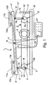
Die
Dem Fachmann ist aus der obigen Beschreibung klar ersichtlich, dass die hier beschriebene Lagerung des Grundelements 4 sowie die Ausbildung der Antriebseinrichtung 5 nur exemplarischen Charakter besitzen. So ist es zum Beispiel auch möglich, dass das Grundelement 4 über entsprechende Führungen (nicht gezeigt) auf- und abbeweglich gelagert ist. Auch ist es nicht erforderlich, dass das Grundelement 4 an zwei Stellen angetrieben wird. Ein Antrieb des Grundelements 4 an nur einer Stelle oder an mehr als zwei Stellen ist ebenfalls möglich, genauso wie ein Antrieb desselben über mehr als eine Antriebseinrichtung. Ebenso wenig ist es zwingend, dass das Grundelement 4 mit einer periodischen Anregung beaufschlagt wird. Auch eine aperiodische Beaufschlagung des Grundelements 4, insbesondere eine stochastische oder impulsförmige Beaufschlagung, ist möglich. Ebenso ist es denkbar, dass das Grundelement 4 anstelle von sinusförmigen Schwingungen oder zusätzlich dazu mit Vibrationen beaufschlagt wird. Vorzugsweise wird hierbei eine Frequenz verwendet, die im Bereich von 0,1 bis 15 Hz bzw. 10 bis 50 Hz liegt. Eine Anregung im erstgenannten Frequenzbereich besitzt den Vorteil, dass hierdurch der Regelkreis des postularen Systems gezielt untersucht werden kann. Der zweitgenannte Bereich erlaubt eine effiziente Analyse der Steifigkeit und Dämpfung des Bewegungsapparates. Dem Fachmann ist klar ersichtlich, welche Modifikationen er an dem beschriebenen Aufbau vorzunehmen hat, um bei der beschriebenen Vorrichtung 1 eine oder mehrere der vorstehend beschriebenen Möglichkeiten vorzusehen. Im folgenden soll jedoch der Einfachheit halber weiterhin von dem in
Die Antriebsbewegung des Elektromotors 6 sowie deren Übertragung über die Antriebsscheiben 8a, 8b und die Pleuel 10 auf das Grundelement 4 bewirkt, dass diese eine sinusförmige Bewegung durchführt, wobei einander gegenüberliegende Enden 4' und 4" des Grundelements 4 eine Phasenverschiebung von 180 ° aufweisen. Der Bewegungsapparat eines auf dem Grundelement 4 stehenden Benutzers wird somit mit einer sinusförmigen Anregung beaufschlagt, woraufhin dieser nun versucht, die Anregungsbewegungen dem Grundelement 4 durch entsprechende Reaktionen seines Bewegungsapparates zu kompensieren. Vorzugsweise ist vorgesehen, dass diese sinusförmige Anregungsfunktion eine Frequenz im Bereich von 5 bis 50 Hz besitzt.The drive movement of the
Auf dem Sockel 2 der Vorrichtung 1 ist ein Abstandssensor 12 angeordnet, durch den die Auslenkung des Grundelements 4 erfassbar ist. Sein Sensorsignal wird über eine Signalleitung 22 zu einer Auswerteeinrichtung 24 geführt und dort entsprechend verarbeitet. Der Abstandssensor 12 erlaubt eine kontinuierliche, quasi-kontinuierliche oder zu diskreten Zeitpunkten stattfindende Erfassung der Lage des Grundelements 4, wobei aus dem zeitlichen Verlauf der Auslenkungsamplituden des Grundelements 4 die Auswerteeinrichtung deren Frequenz und/oder Amplitude, insbesondere die zur aktuellen Auslenkung des Grundelements korrelierte Momentanamplitude, sowie daraus ableitbare Bewegungsparameter des Grundelements 4 ermitteln werden können. Bevorzugt wird hierbei, dass die Amplitude und/oder die Frequenz der Auslenkung des Grundelements 4 in seiner Wirkrichtung, im hier gezeigten Fall also in der horizontalen Richtung, erfasst bzw. ermittelt werden.On the
Anstelle des Abstandssensors 12 kann auch ein anderer Sensortyp, zum Beispiel ein Kraft-, Druck-, Weg-, Geschwindigkeits- oder Beschleunigungssensor eingesetzt werden, solange gewährleistet ist, dass durch den entsprechenden Sensor die Anregungsbewegung des Grundelements 4 der Vorrichtung 1 in seiner Wirkrichtung erfassbar ist.Instead of the
Wie aus den
Um nun zur Durchführung eines Trainings und/oder einer Analyse eines Bewegungsapparates des Benutzers dessen Antwort auf die durch die Vorrichtung 1 aufgebrachte Anregung ermitteln zu können, ist vorgesehen, dass die Vorrichtung 1 einen oder mehrere entsprechend ausgebildete Sensoren aufweist, mit denen die Antwort des Bewegungsapparats des Benutzers auf die Anregung erfassbar ist. Im hier beschriebenen Fall, bei dem auf der Grundplatte Trittplattformen 11a, 11 b angeordnet sind, ist vorgesehen, dass - wie am besten aus
Die drei Sensoren 13a-13c, 13a'-13c' sind hierbei vorzugsweise nicht-kollinear angeordnet, so dass hierdurch nicht nur die vom Benutzer auf die jeweilige Trittplattform 11a, 11b aufgebrachten Druckkräfte erfassbar ist, sondern dass aus der räumlichen Beziehung der drei Sensoren 13a-13c; 13a'-13c' der Schwerpunkt der Kraftverteilung und somit der Gesamt-Krafteinleitpunkt ermittelbar ist. Dies erlaubt die genaue Erfassung der Position des Fußes des Benutzers auf der ersten und der zweiten Trittplattform 11a, 11 b, woraus wieder die genaue Amplitude der den Fuß beaufschlagende Anregung ermittelbar ist. Es ist aber auch möglich, weniger oder mehr Sensoren zu verwenden oder nur einen einzigen Sensor pro Trittplattform 11a, 11 b zu verwenden, der aber dann vorzugsweise auflösend ausgeführt ist. Die Verwendung eines oder mehrerer ortsauflösender Sensoren auf der oder den Trittplattformen 11a, 11b und/oder auf dem Grundelement 4 erlaubt in vorteilhafter Art und Weise eine örtlich aufgelöste Erfassung der vom Benutzer hervorgerufene Druck- oder Kraftverteilung. Wenn auf die Trittplattformen 11a, 11 b verzichtet werden soll, so kann dann der entsprechende Bereich des Grundelements 4 mit zur Erfassung der Krafteinleitung geeigneten Sensoren, insbesondere der vorstehend beschriebenen Sensoren, versehen sein.The three
Ein Vergleich dieser beiden Funktionen erlaubt es nun, die mit der Vorrichtung 1 bewirkte Anregung einerseits und die Reaktion des Benutzers andererseits zueinander in Beziehung zu setzen und durch die Auswertung insbesondere der Amplituden, der Kurvenformen, der Frequenzkomponenten der Kurvenformen und/oder der Phasenlage der beiden Funktionen auf Charakteristika und/oder eine etwaige Fehlfunktion des Bewegungsapparates zu schließen.A comparison of these two functions now makes it possible to relate the excitation caused by the
Beim ersten Ausführungsbeispiel ist die von dem Grundelement 4 auf den Benutzer aufgeprägte Anregungsfunktion eine sinusförmige Funktion, wobei die maximale Auslenkung des in der
Betrachtet man nun den Bewegungsapparat des Benutzers als ein wegerregtes Feder-Masse-Dämpfungssystem, so würde bei einem reinen Feder-Masse-System die Phasenverschiebung zwischen der maximalen Auslenkung der Grundplatte 4 und dem Maximalwert der vom Benutzer auf das Grundelement 4 aufgebrachten Kraft 0°, bei einem rein dämpfenden System, bei dem die resultierende Kraft von der auf den Benutzer aufgebrachten Geschwindigkeit der Grundplatte 4 abhängt, hingegen 90 ° betragen. Analysiert man nun die Antwortfunktion des Benutzers auf die von der Vorrichtung 1 vorgegebene Anregungsfunktion der Vorrichtung 1 hinsichtlich der Amplitude und/oder der Phasenlage dieser beiden Funktionen, so können in einer dem Fachmann bekannten Art und Weise kinematische Kenngrößen des Bewegungsapparates wie Steifigkeitskoeffizient oder Dämpfungskoeffizient insbesondere im Rahmen des vorgenannten Feder-Masse-Dämpfungs-Systems bestimmt werden.Considering the musculoskeletal system of the user as a wegerregtes spring-mass damping system, so in a pure spring-mass system, the phase shift between the maximum deflection of the
Die
In den
Der wesentliche Unterschied zu den beiden vorgenannten Ausführungsbeispielen besteht darin, dass das Grundelement 4 zweiteilig ausgeführt ist, dass also hier zwei Teil-Grundelemente 4a und 4b vorhanden sind, die zusammenwirkend die Funktion des Grundelements 4 der ersten beiden Ausführungsbeispiele realisieren. Der Vorteil einer derartigen Konstruktion ist, dass hier die beiden Teil-Grundelemente 4a und 4b unabhängig voneinander bewegt werden können. Die beschriebene Vorrichtung 1 erlaubt es somit in vorteilhafter Art und Weise, den Bewegungsapparat des Benutzers nur einseitig oder seitenspezifisch unterschiedlich stark anzuregen, indem zum Beispiel ein Teil-Grundelement 4a nicht und das zweite Teil-Grundelement 4b wie vorstehend in Schwingungen versetzt wird, oder dass die Amplitude und/oder die Frequenz der Schwingungen der beiden Teil-Grundelemente 4a, 4b unterschiedlich ausgeprägt sind. Insbesondere in diesem Fall ist es dann vorteilhaft, dass die dem jeweiligen Grund-Teilelementen 4a, 4b zugeordneten Sensoren getrennt ausgewertet werden.The essential difference to the two aforementioned embodiments is that the
In den
Von besonderem Vorteil ist, wenn der Auswerteeinrichtung der Vorrichtung das Signal mindestens eines weiteren Sensors zuführbar ist, durch den oder die die Übertragung der Anregungsfunktion von den durch das Grundelement 4, 4a, 4b beaufschlagbaren Extremitäten des Benutzers auf einen weiteren Bereich des Bewegungsapparates erfassbar ist. Es wäre zum Beispiel möglich, Positions-, Weg-, Geschwindigkeits-, oder Beschleunigungssensoren an weiteren Körperteilen des Benutzers, insbesondere am Kopf, anzubringen und die Bewegung des Körperteils, insbesondere der des Kopfes, zu erfassen. Eine möglichst geringe Bewegung des Kopfes weist zum Beispiel auf eine große Elastizität der Wirbelsäule und der Rückenmuskulatur des Benutzers hin, eine starke Bewegung des Kopfes hingegen lässt auf eine geringe Elastizität, die zum Beispiel durch eine Versteifung der Rückenmuskulatur verursacht wird, schließen.It is particularly advantageous if the evaluation device of the device, the signal of at least one further sensor can be fed, by or the transmission of the excitation function of the actuatable by the
In
Von weiterem Vorteil ist die Ergänzung der Messeinrichtung durch Sensoren zur Erfassung der Körperhaltung des Benutzers auf der Vorrichtung 1, zum Beispiel durch Verwendung eines ortsauflösenden Kraft- und Drucksensors in optionaler Kombination mit einem Gelenkwinkelsensor, zum Beispiel einem Goniomenter zur Erfassung des Kniewinkels. Auf diese Weise kann durch die Vorrichtung 1 in einfacher Art und Weise ermittelt werden, ob die Kräfte über den Vorfuß oder die Fersen in den Körper eingeleitet werden, was zur Aktivierung unterschiedlicher Muskelgruppen (z. B. vorwiegend Unterschenkel/Wade oder Oberschenkel) führt. Dies kann durch die zusätzliche oder alternative Auswertung des Kniewinkels weiter verfeinert werden. Die vorstehend beschriebenen zusätzlichen sensorischen Informationen erhöhen zum einen den Informationsgehalt der Analyse, zum anderen kann auf deren Basis ein Training auf der Vorrichtung 1 wesentlich besser gesteuert und somit deutlich optimiert werden.Another advantage is the addition of the measuring device by sensors for detecting the posture of the user on the
Bei den vier vorstehend beschriebenen Ausführungsbeispielen wurde davon ausgegangen, dass das Grundelement 4 als eine Grundplatte ausgebildet ist, auf denen der Benutzer der Vorrichtung 1 mit einem oder beiden Füßen steht. Die Vorrichtung 1 ist aber nicht darauf beschränkt, dass über die Füße in den Bewegungsapparat des Benutzers die von dem Grundelement 4 vermittelte Anregungsfunktion eingeleitet wird. Es ist zum Beispiel auch möglich, dass das Grundelement 4 als ein Reck, als ein Griff oder als eine Hantel ausgebildet ist, so dass dann die Einleitung der Anregungsfunktion in den Bewegungsapparat des Benutzers über eine oder beide Hände erfolgt. Auch eine Kombination zwischen einem als Grundplatte ausgebildeten ersten Teil-Grundelement 4a und einem als Griff, etc. ausgebildeten zweiten Teil-Grundelement 4b ist möglich.In the four embodiments described above, it has been assumed that the
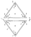
In
In
Die vorstehend beschriebene Vorrichtung 1 ist nicht nur zur Analyse des Bewegungsapparates eines Benutzers geeignet. Sie kann auch für Therapiezwecke verwendet werden, insbesondere für einen gezielten Aufbau von bestimmten Muskeln oder der Muskulatur allgemein, wobei durch einen Vergleich der Anregungsfunktion und der Antwortfunktion des Benutzers eine Optimierung der durch die Vorrichtung 1 hervorgerufenen Anregungsfunktion erzielbar ist.The
Zusammenfassend ist festzustellen, dass durch die Vorrichtung 1 eine zum Training und/oder zur Analyse des Bewegungsapparates eines Benutzers besonders geeignete Vorrichtung geschaffen wurde, welche sich dadurch auszeichnet, dass durch einen Vergleich der von der Vorrichtung 1 bewirkten Anregungsfunktion auf den Bewegungsapparat und der Antwortfunktion zumindest eine Verbesserung, wenn nicht eine Optimierung, des Trainings und/oder der Analyse erzielbar ist.In summary, it should be noted that by the
Claims (19)
- Apparatus for exercise and/or analysis of the locomotor system of a user, the apparatus (1) having at least one basic element (4; 4a, 4b), which can be put into periodic and/or aperiodic movements by a driving device (5) for generating an excitation function acting upon the user, and having at least one sensor (13; 13a-13c, 13a'-13c') for detecting a response function of the user of the apparatus (1) to the excitation function applied to the basic element (4), the sensor signals of the sensor or the sensors are led to an evaluation device (24) of the apparatus (1), characterized in that the apparatus (1) has at least one further sensor (12; 12a-12c), by which the position and/or the state of movement of the basic element (4; 4a, 4b) excited by the excitation function of the apparatus (1) and acting upon the user can be captured and its or their sensor signals are leadable to the evaluation device (24), and that the evaluation device (24) is capable of performing a comparison of the excitation function applied to the user by the basic element (4; 4a, 4b) and the response function of the user in that the evaluation device (24) compares the amplitude and/or the phasing of these two functions for the determination of parameters of the locomotor system of the user.
- Apparatus according to claim 1, characterized in that the further sensor (12; 12a-12c) is a distance sensor by which the position of the basic element (4) can be detected.
- Apparatus according to claim 1, characterized in that the further sensor (12; 12a-12c) is a force sensor, a pressure sensor, a path sensor, a velocity sensor or an acceleration sensor.
- Apparatus according to one of the previous claims, characterized in that the evaluation device (24) evaluates the sensor signal or the sensor signals of the further sensor or the further sensors (12; 12a-12c) continuously, quasi-continuously or at discrete points in time.
- Apparatus according to one of the previous claims, characterized in that on the basic element (4; 4a, 4b) at least one sensor (13a-13c; 13a'-13c') is arranged, by which the force and/or the pressure exerted by the user on the basic element (4; 4a, 4b) can be detected.
- Apparatus according to claim 1 or 5, characterized in that at least one sensor is position sensitive.
- Apparatus according to one of the previous claims, characterized in that the basic element (4) is formed as one-piece.
- Apparatus according to one of the previous claims 1-6, characterized in that the basic element (4) has got at least two basic element parts (4a, 4b).
- Apparatus according to one of the previous claims, characterized in that the basic element (4; 4a, 4b) is provided as a ground plate.
- Apparatus according to one of the previous claims, characterized in that the apparatus (1) has got at least one foot platform (11 a, 11 b).
- Apparatus according to claim 10, characterized in that below the foot platform or below at least one of the foot platforms (11 a, 11 b) at least one sensor (13a-13c; 13a'-13c') is arranged.
- Apparatus according to claim 1, characterized in that the basic element (4) of the apparatus is formed highbar-like.
- Apparatus according to claim 12, characterized in that the highbar-like basic element (4) has got two grips (30a, 30b), which can be driven by the excitation function by the driving device (5).
- Apparatus according to claim 1, characterized in that the basic element (4) of the apparatus (1) is formed dumbbell-like.
- Apparatus according to claim 14, characterized in that the dumbbell-like basic element (4) has got a dumbbell bar (31), which can be driven by the excitation function by the driving device (5).
- apparatus according to one of the previous claims, characterized in that sensor signals of at least one further, external sensor (26, 27) can be lead to the evaluation device (24).
- Apparatus according to one of the previous claims, characterized in that the apparatus includes further electrodes (27), by which electric currents and/or electric tensions of the body of the user can be gathered.
- Apparatus according to claim 16 or claim 17, characterized in that the transmission of the excitation function on the locomotor system of the user can be gathered by the at least one external sensor (26) and/or the electrodes (27).
- Method for the training and/or analysis of the locomotor system of the user, where by means of an apparatus (1) for generating an excitation function mechanical excitations are impacted upon the user, and wherein the response function of the user to the excitation function generated by the apparatus (1) is gathered, characterized in that the excitation function of the apparatus (1) is gathered via at least one sensor (12; 12a-12c), and that in an evaluation device (24) the excitation function generated by the apparatus (1) and acting upon the user is compared with a response function of the user in that the evaluation device (24) compares the amplitude and/or the phasing of these two functions for the determination of parameters of the locomotor system of the user.
Applications Claiming Priority (3)
| Application Number | Priority Date | Filing Date | Title |
|---|---|---|---|
| DE200720008887 DE202007008887U1 (en) | 2007-06-22 | 2007-06-22 | Device for training and / or analyzing the musculoskeletal system of a user |
| DE102007029311A DE102007029311A1 (en) | 2007-06-22 | 2007-06-22 | Device for training or analysis of locomotors system of user, has base element that is displaceable into periodic and aperiodic movements by driving device |
| PCT/EP2008/005051 WO2009000487A1 (en) | 2007-06-22 | 2008-06-23 | Apparatus and method for exercise and/or analysis of the locomotor system of a user |
Publications (2)
| Publication Number | Publication Date |
|---|---|
| EP2160168A1 EP2160168A1 (en) | 2010-03-10 |
| EP2160168B1 true EP2160168B1 (en) | 2011-12-07 |
Family
ID=39772844
Family Applications (1)
| Application Number | Title | Priority Date | Filing Date |
|---|---|---|---|
| EP08773588A Active EP2160168B1 (en) | 2007-06-22 | 2008-06-23 | Apparatus and method for exercise and/or analysis of the locomotor system of a user |
Country Status (3)
| Country | Link |
|---|---|
| EP (1) | EP2160168B1 (en) |
| AT (1) | ATE536161T1 (en) |
| WO (1) | WO2009000487A1 (en) |
Cited By (4)
| Publication number | Priority date | Publication date | Assignee | Title |
|---|---|---|---|---|
| DE202013003859U1 (en) | 2013-04-25 | 2014-07-28 | Hans Schiessl | Device for training and / or analyzing the musculoskeletal system of a user |
| DE202013010263U1 (en) | 2013-04-25 | 2014-07-30 | Hans Schiessl | Device for training and / or analyzing the musculoskeletal system of a user |
| WO2014173545A1 (en) | 2013-04-25 | 2014-10-30 | Hans Schiessl | Apparatus for training and/or analysis of the musculoskeletal system of a user |
| CN105307733A (en) * | 2013-03-15 | 2016-02-03 | 威斯技术基金会公司 | Musculoskeletal vibration system providing independent vibration and bias control |
Families Citing this family (10)
| Publication number | Priority date | Publication date | Assignee | Title |
|---|---|---|---|---|
| US8128537B2 (en) * | 2009-06-29 | 2012-03-06 | Concept One International Llc | Vibratory exercise device with low center of gravity and modular weights |
| ITMI20091252A1 (en) * | 2009-07-14 | 2011-01-15 | Danilo Mantovani | MODULAR PROPRIOCEPTIVE TABLE PROVIDED WITH MEANS OF DETECTION OF TILTING AND ROTATION |
| IT1397957B1 (en) | 2010-02-05 | 2013-02-04 | Bosco System Lab S P A | VIBRATING PLATFORM. |
| DE102010012676A1 (en) * | 2010-03-24 | 2011-09-29 | Helmut Frey | Device for muscle stimulation |
| IT1403374B1 (en) * | 2010-10-29 | 2013-10-17 | Bosco System Lab S P A | APPARATUS FOR THE TRANSMISSION OF LOCALIZED VIBRATIONS, IN PARTICULAR TO MUSCLES OF A USER. |
| IT1403126B1 (en) * | 2010-10-29 | 2013-10-04 | Bosco System Lab S P A | EQUIPMENT FOR PHYSICAL EXERCISE INCLUDING A VIBRATING HANDLEBAR. |
| GB201117550D0 (en) | 2011-10-11 | 2011-11-23 | Henson Timothy G | Exercise machine |
| WO2014201584A1 (en) * | 2013-06-19 | 2014-12-24 | 翔天电子实业有限公司 | Fitness device having stepping and hip-lifting functions |
| DE102016110741A1 (en) * | 2016-06-10 | 2017-12-14 | Logicdata Electronic & Software Entwicklungs Gmbh | Massage system and method for controlling a massage actuator |
| CN107296617B (en) * | 2017-06-22 | 2019-10-25 | 四川东鼎里智信息技术有限责任公司 | The monitoring method of muscle explosive force |
Family Cites Families (8)
| Publication number | Priority date | Publication date | Assignee | Title |
|---|---|---|---|---|
| US6217491B1 (en) * | 1996-08-26 | 2001-04-17 | Hans Schiessl | Device for stimulating muscles |
| DE19634396B4 (en) | 1996-08-26 | 2008-03-27 | Schiessl, Hans | Device for stimulating musculoskeletal muscles |
| DE19846982C2 (en) | 1998-10-12 | 2001-05-17 | Siemens Ag | Method and system for monitoring a user's posture on exercise equipment |
| AU782159B2 (en) | 2000-01-31 | 2005-07-07 | Bosco, Alessandro | Automatic device for optimised muscular stimulation |
| JP3899403B2 (en) | 2002-08-27 | 2007-03-28 | 独立行政法人産業技術総合研究所 | Balance training equipment |
| ITRM20040640A1 (en) | 2004-12-27 | 2005-03-27 | Bosco Carla Marta Stefania | GYMNASTIC TOOL OR MACHINE WITH INCREASED NEUROMUSCULAR MECHANICAL STIMULATION. |
| DE202005002086U1 (en) | 2005-02-10 | 2005-04-21 | Marciniak, Michael | Vibration training device for sports training and physiotherapy has vibration sensor unit for attachment to body of user that transmits vibration signals to controller, which regulates vibration generator to match body's vibrations |
| DE102007014080A1 (en) * | 2006-03-21 | 2007-09-27 | Lautenschläger, jens | Training device for use as therapeutic device, has sensor provided for targeted measurement of movements or movement course/sequence of training, and terminal provided such that sequence is provided and/or implemented based on training |
-
2008
- 2008-06-23 WO PCT/EP2008/005051 patent/WO2009000487A1/en active Application Filing
- 2008-06-23 AT AT08773588T patent/ATE536161T1/en active
- 2008-06-23 EP EP08773588A patent/EP2160168B1/en active Active
Cited By (5)
| Publication number | Priority date | Publication date | Assignee | Title |
|---|---|---|---|---|
| CN105307733A (en) * | 2013-03-15 | 2016-02-03 | 威斯技术基金会公司 | Musculoskeletal vibration system providing independent vibration and bias control |
| DE202013003859U1 (en) | 2013-04-25 | 2014-07-28 | Hans Schiessl | Device for training and / or analyzing the musculoskeletal system of a user |
| DE202013010263U1 (en) | 2013-04-25 | 2014-07-30 | Hans Schiessl | Device for training and / or analyzing the musculoskeletal system of a user |
| WO2014173545A1 (en) | 2013-04-25 | 2014-10-30 | Hans Schiessl | Apparatus for training and/or analysis of the musculoskeletal system of a user |
| DE102013007131B4 (en) | 2013-04-25 | 2018-08-16 | Hans Schiessl | Device for training and / or analyzing the musculoskeletal system of a user |
Also Published As
| Publication number | Publication date |
|---|---|
| WO2009000487A1 (en) | 2008-12-31 |
| EP2160168A1 (en) | 2010-03-10 |
| ATE536161T1 (en) | 2011-12-15 |
Similar Documents
| Publication | Publication Date | Title |
|---|---|---|
| EP2160168B1 (en) | Apparatus and method for exercise and/or analysis of the locomotor system of a user | |
| DE102016217307B4 (en) | pedometer, walking assistance device and computer program product | |
| DE202007008887U1 (en) | Device for training and / or analyzing the musculoskeletal system of a user | |
| EP3644852A1 (en) | Measuring method and apparatus for determining the length conditions, the position and/or the radius of movement of the lower extremities of a bed-bound patient | |
| DE102006005409B4 (en) | measuring device | |
| DE102013007131B4 (en) | Device for training and / or analyzing the musculoskeletal system of a user | |
| EP2097002B1 (en) | Device and method for capturing a gait pattern | |
| EP2988835B1 (en) | Apparatus for training and/or analysis of the musculoskeletal system of a user | |
| DE102007046895A1 (en) | Test and training device for determining physical constitution of test person, has restraint guide for restraint coordination of movement of person, where device carries out squat on person under utilization of controlled resistance | |
| DE102016104252A1 (en) | Foot shell for a movement therapy device and exercise therapy device | |
| DE102010003342B4 (en) | Treadmill device | |
| DE102019129376B4 (en) | Device and method for controlling devices that generate external loads on the human and animal body | |
| DE102007029311A1 (en) | Device for training or analysis of locomotors system of user, has base element that is displaceable into periodic and aperiodic movements by driving device | |
| WO2016116100A1 (en) | Training apparatus for improving force, mobility, endurance and control at the level of various joints and the soft tissue structures surrounding them | |
| DE102020105553B3 (en) | ADAPTIVE ACTIVE TRAINING SYSTEM | |
| DE102007014080A1 (en) | Training device for use as therapeutic device, has sensor provided for targeted measurement of movements or movement course/sequence of training, and terminal provided such that sequence is provided and/or implemented based on training | |
| DE102005027329B4 (en) | Device for the diagnosis and therapy of the trunk musculature, in particular for the coordination training therapy of the musculature of the lumbar spine | |
| DE10312042B4 (en) | Training device with continuously rotatably movable, interconnected actuators | |
| DE202013003859U1 (en) | Device for training and / or analyzing the musculoskeletal system of a user | |
| DE102006053348A1 (en) | Living being e.g. horse, gait pattern capturing device, has sensor detecting individual tread pulses of dynamic sequence of movements, which consist of sequence of individual movements, and supplying sensor signal to evaluation device | |
| DE102017124454B4 (en) | Training and diagnostic device for the hip and pelvic muscles in the sports and rehabilitation area | |
| DE202008002943U1 (en) | Hip joint orthosis with electrostimulation | |
| DE102011106228A1 (en) | Method for visual representation of gait parameters in line with device-supported gait therapy using sensor element for measurement of forces or moments, involves measuring exerted forces or moments | |
| EP1842486A1 (en) | Therapy device and operating method | |
| DE102011106231A1 (en) | Therapeutic device for gait analysis and/or for gait rehabilitation of stroke patient, has sensor element which is provided for measuring the forces and/or moments excreted on the base plates |
Legal Events
| Date | Code | Title | Description |
|---|---|---|---|
| PUAI | Public reference made under article 153(3) epc to a published international application that has entered the european phase |
Free format text: ORIGINAL CODE: 0009012 |
|
| 17P | Request for examination filed |
Effective date: 20100122 |
|
| AK | Designated contracting states |
Kind code of ref document: A1 Designated state(s): AT BE BG CH CY CZ DE DK EE ES FI FR GB GR HR HU IE IS IT LI LT LU LV MC MT NL NO PL PT RO SE SI SK TR |
|
| AX | Request for extension of the european patent |
Extension state: AL BA MK RS |
|
| DAX | Request for extension of the european patent (deleted) | ||
| GRAP | Despatch of communication of intention to grant a patent |
Free format text: ORIGINAL CODE: EPIDOSNIGR1 |
|
| GRAC | Information related to communication of intention to grant a patent modified |
Free format text: ORIGINAL CODE: EPIDOSCIGR1 |
|
| GRAS | Grant fee paid |
Free format text: ORIGINAL CODE: EPIDOSNIGR3 |
|
| GRAA | (expected) grant |
Free format text: ORIGINAL CODE: 0009210 |
|
| AK | Designated contracting states |
Kind code of ref document: B1 Designated state(s): AT BE BG CH CY CZ DE DK EE ES FI FR GB GR HR HU IE IS IT LI LT LU LV MC MT NL NO PL PT RO SE SI SK TR |
|
| REG | Reference to a national code |
Ref country code: GB Ref legal event code: FG4D Free format text: NOT ENGLISH |
|
| REG | Reference to a national code |
Ref country code: CH Ref legal event code: EP |
|
| REG | Reference to a national code |
Ref country code: IE Ref legal event code: FG4D Free format text: LANGUAGE OF EP DOCUMENT: GERMAN |
|
| REG | Reference to a national code |
Ref country code: DE Ref legal event code: R096 Ref document number: 502008005794 Country of ref document: DE Effective date: 20120209 |
|
| REG | Reference to a national code |
Ref country code: NL Ref legal event code: VDEP Effective date: 20111207 |
|
| PG25 | Lapsed in a contracting state [announced via postgrant information from national office to epo] |
Ref country code: NO Free format text: LAPSE BECAUSE OF FAILURE TO SUBMIT A TRANSLATION OF THE DESCRIPTION OR TO PAY THE FEE WITHIN THE PRESCRIBED TIME-LIMIT Effective date: 20120307 Ref country code: LT Free format text: LAPSE BECAUSE OF FAILURE TO SUBMIT A TRANSLATION OF THE DESCRIPTION OR TO PAY THE FEE WITHIN THE PRESCRIBED TIME-LIMIT Effective date: 20111207 |
|
| LTIE | Lt: invalidation of european patent or patent extension |
Effective date: 20111207 |
|
| PG25 | Lapsed in a contracting state [announced via postgrant information from national office to epo] |
Ref country code: GR Free format text: LAPSE BECAUSE OF FAILURE TO SUBMIT A TRANSLATION OF THE DESCRIPTION OR TO PAY THE FEE WITHIN THE PRESCRIBED TIME-LIMIT Effective date: 20120308 Ref country code: HR Free format text: LAPSE BECAUSE OF FAILURE TO SUBMIT A TRANSLATION OF THE DESCRIPTION OR TO PAY THE FEE WITHIN THE PRESCRIBED TIME-LIMIT Effective date: 20111207 Ref country code: SI Free format text: LAPSE BECAUSE OF FAILURE TO SUBMIT A TRANSLATION OF THE DESCRIPTION OR TO PAY THE FEE WITHIN THE PRESCRIBED TIME-LIMIT Effective date: 20111207 Ref country code: SE Free format text: LAPSE BECAUSE OF FAILURE TO SUBMIT A TRANSLATION OF THE DESCRIPTION OR TO PAY THE FEE WITHIN THE PRESCRIBED TIME-LIMIT Effective date: 20111207 Ref country code: LV Free format text: LAPSE BECAUSE OF FAILURE TO SUBMIT A TRANSLATION OF THE DESCRIPTION OR TO PAY THE FEE WITHIN THE PRESCRIBED TIME-LIMIT Effective date: 20111207 Ref country code: NL Free format text: LAPSE BECAUSE OF FAILURE TO SUBMIT A TRANSLATION OF THE DESCRIPTION OR TO PAY THE FEE WITHIN THE PRESCRIBED TIME-LIMIT Effective date: 20111207 |
|
| PG25 | Lapsed in a contracting state [announced via postgrant information from national office to epo] |
Ref country code: CY Free format text: LAPSE BECAUSE OF FAILURE TO SUBMIT A TRANSLATION OF THE DESCRIPTION OR TO PAY THE FEE WITHIN THE PRESCRIBED TIME-LIMIT Effective date: 20111207 |
|
| REG | Reference to a national code |
Ref country code: IE Ref legal event code: FD4D |
|
| PG25 | Lapsed in a contracting state [announced via postgrant information from national office to epo] |
Ref country code: IE Free format text: LAPSE BECAUSE OF FAILURE TO SUBMIT A TRANSLATION OF THE DESCRIPTION OR TO PAY THE FEE WITHIN THE PRESCRIBED TIME-LIMIT Effective date: 20111207 Ref country code: BG Free format text: LAPSE BECAUSE OF FAILURE TO SUBMIT A TRANSLATION OF THE DESCRIPTION OR TO PAY THE FEE WITHIN THE PRESCRIBED TIME-LIMIT Effective date: 20120307 Ref country code: EE Free format text: LAPSE BECAUSE OF FAILURE TO SUBMIT A TRANSLATION OF THE DESCRIPTION OR TO PAY THE FEE WITHIN THE PRESCRIBED TIME-LIMIT Effective date: 20111207 Ref country code: IS Free format text: LAPSE BECAUSE OF FAILURE TO SUBMIT A TRANSLATION OF THE DESCRIPTION OR TO PAY THE FEE WITHIN THE PRESCRIBED TIME-LIMIT Effective date: 20120407 Ref country code: CZ Free format text: LAPSE BECAUSE OF FAILURE TO SUBMIT A TRANSLATION OF THE DESCRIPTION OR TO PAY THE FEE WITHIN THE PRESCRIBED TIME-LIMIT Effective date: 20111207 Ref country code: SK Free format text: LAPSE BECAUSE OF FAILURE TO SUBMIT A TRANSLATION OF THE DESCRIPTION OR TO PAY THE FEE WITHIN THE PRESCRIBED TIME-LIMIT Effective date: 20111207 |
|
| PG25 | Lapsed in a contracting state [announced via postgrant information from national office to epo] |
Ref country code: RO Free format text: LAPSE BECAUSE OF FAILURE TO SUBMIT A TRANSLATION OF THE DESCRIPTION OR TO PAY THE FEE WITHIN THE PRESCRIBED TIME-LIMIT Effective date: 20111207 Ref country code: PT Free format text: LAPSE BECAUSE OF FAILURE TO SUBMIT A TRANSLATION OF THE DESCRIPTION OR TO PAY THE FEE WITHIN THE PRESCRIBED TIME-LIMIT Effective date: 20120409 Ref country code: PL Free format text: LAPSE BECAUSE OF FAILURE TO SUBMIT A TRANSLATION OF THE DESCRIPTION OR TO PAY THE FEE WITHIN THE PRESCRIBED TIME-LIMIT Effective date: 20111207 |
|
| PLBE | No opposition filed within time limit |
Free format text: ORIGINAL CODE: 0009261 |
|
| STAA | Information on the status of an ep patent application or granted ep patent |
Free format text: STATUS: NO OPPOSITION FILED WITHIN TIME LIMIT |
|
| PG25 | Lapsed in a contracting state [announced via postgrant information from national office to epo] |
Ref country code: DK Free format text: LAPSE BECAUSE OF FAILURE TO SUBMIT A TRANSLATION OF THE DESCRIPTION OR TO PAY THE FEE WITHIN THE PRESCRIBED TIME-LIMIT Effective date: 20111207 |
|
| 26N | No opposition filed |
Effective date: 20120910 |
|
| PG25 | Lapsed in a contracting state [announced via postgrant information from national office to epo] |
Ref country code: IT Free format text: LAPSE BECAUSE OF FAILURE TO SUBMIT A TRANSLATION OF THE DESCRIPTION OR TO PAY THE FEE WITHIN THE PRESCRIBED TIME-LIMIT Effective date: 20111207 |
|
| BERE | Be: lapsed |
Owner name: SCHIESSL, HANS Effective date: 20120630 |
|
| REG | Reference to a national code |
Ref country code: DE Ref legal event code: R097 Ref document number: 502008005794 Country of ref document: DE Effective date: 20120910 |
|
| PG25 | Lapsed in a contracting state [announced via postgrant information from national office to epo] |
Ref country code: MC Free format text: LAPSE BECAUSE OF NON-PAYMENT OF DUE FEES Effective date: 20120630 |
|
| REG | Reference to a national code |
Ref country code: FR Ref legal event code: ST Effective date: 20130228 |
|
| PG25 | Lapsed in a contracting state [announced via postgrant information from national office to epo] |
Ref country code: BE Free format text: LAPSE BECAUSE OF NON-PAYMENT OF DUE FEES Effective date: 20120630 Ref country code: ES Free format text: LAPSE BECAUSE OF FAILURE TO SUBMIT A TRANSLATION OF THE DESCRIPTION OR TO PAY THE FEE WITHIN THE PRESCRIBED TIME-LIMIT Effective date: 20120318 Ref country code: FR Free format text: LAPSE BECAUSE OF NON-PAYMENT OF DUE FEES Effective date: 20120702 |
|
| PG25 | Lapsed in a contracting state [announced via postgrant information from national office to epo] |
Ref country code: FI Free format text: LAPSE BECAUSE OF FAILURE TO SUBMIT A TRANSLATION OF THE DESCRIPTION OR TO PAY THE FEE WITHIN THE PRESCRIBED TIME-LIMIT Effective date: 20111207 |
|
| PG25 | Lapsed in a contracting state [announced via postgrant information from national office to epo] |
Ref country code: MT Free format text: LAPSE BECAUSE OF FAILURE TO SUBMIT A TRANSLATION OF THE DESCRIPTION OR TO PAY THE FEE WITHIN THE PRESCRIBED TIME-LIMIT Effective date: 20111207 |
|
| PG25 | Lapsed in a contracting state [announced via postgrant information from national office to epo] |
Ref country code: TR Free format text: LAPSE BECAUSE OF FAILURE TO SUBMIT A TRANSLATION OF THE DESCRIPTION OR TO PAY THE FEE WITHIN THE PRESCRIBED TIME-LIMIT Effective date: 20111207 |
|
| PG25 | Lapsed in a contracting state [announced via postgrant information from national office to epo] |
Ref country code: LU Free format text: LAPSE BECAUSE OF NON-PAYMENT OF DUE FEES Effective date: 20120623 |
|
| PG25 | Lapsed in a contracting state [announced via postgrant information from national office to epo] |
Ref country code: HU Free format text: LAPSE BECAUSE OF FAILURE TO SUBMIT A TRANSLATION OF THE DESCRIPTION OR TO PAY THE FEE WITHIN THE PRESCRIBED TIME-LIMIT Effective date: 20080623 |
|
| PGFP | Annual fee paid to national office [announced via postgrant information from national office to epo] |
Ref country code: DE Payment date: 20230419 Year of fee payment: 16 |
|
| PGFP | Annual fee paid to national office [announced via postgrant information from national office to epo] |
Ref country code: AT Payment date: 20230414 Year of fee payment: 16 |
|
| PGFP | Annual fee paid to national office [announced via postgrant information from national office to epo] |
Ref country code: GB Payment date: 20230413 Year of fee payment: 16 Ref country code: CH Payment date: 20230701 Year of fee payment: 16 |