EP2157907B1 - Electrochemical biosensors and arrays - Google Patents
Electrochemical biosensors and arrays Download PDFInfo
- Publication number
- EP2157907B1 EP2157907B1 EP08770378A EP08770378A EP2157907B1 EP 2157907 B1 EP2157907 B1 EP 2157907B1 EP 08770378 A EP08770378 A EP 08770378A EP 08770378 A EP08770378 A EP 08770378A EP 2157907 B1 EP2157907 B1 EP 2157907B1
- Authority
- EP
- European Patent Office
- Prior art keywords
- reservoir
- electrode
- sensor device
- sensor
- cap
- Prior art date
- Legal status (The legal status is an assumption and is not a legal conclusion. Google has not performed a legal analysis and makes no representation as to the accuracy of the status listed.)
- Not-in-force
Links
Images


Classifications
-
- A—HUMAN NECESSITIES
- A61—MEDICAL OR VETERINARY SCIENCE; HYGIENE
- A61B—DIAGNOSIS; SURGERY; IDENTIFICATION
- A61B5/00—Measuring for diagnostic purposes; Identification of persons
- A61B5/145—Measuring characteristics of blood in vivo, e.g. gas concentration, pH value; Measuring characteristics of body fluids or tissues, e.g. interstitial fluid, cerebral tissue
- A61B5/1486—Measuring characteristics of blood in vivo, e.g. gas concentration, pH value; Measuring characteristics of body fluids or tissues, e.g. interstitial fluid, cerebral tissue using enzyme electrodes, e.g. with immobilised oxidase
- A61B5/14865—Measuring characteristics of blood in vivo, e.g. gas concentration, pH value; Measuring characteristics of body fluids or tissues, e.g. interstitial fluid, cerebral tissue using enzyme electrodes, e.g. with immobilised oxidase invasive, e.g. introduced into the body by a catheter or needle or using implanted sensors
-
- A—HUMAN NECESSITIES
- A61—MEDICAL OR VETERINARY SCIENCE; HYGIENE
- A61B—DIAGNOSIS; SURGERY; IDENTIFICATION
- A61B5/00—Measuring for diagnostic purposes; Identification of persons
- A61B5/145—Measuring characteristics of blood in vivo, e.g. gas concentration, pH value; Measuring characteristics of body fluids or tissues, e.g. interstitial fluid, cerebral tissue
- A61B5/14532—Measuring characteristics of blood in vivo, e.g. gas concentration, pH value; Measuring characteristics of body fluids or tissues, e.g. interstitial fluid, cerebral tissue for measuring glucose, e.g. by tissue impedance measurement
-
- C—CHEMISTRY; METALLURGY
- C12—BIOCHEMISTRY; BEER; SPIRITS; WINE; VINEGAR; MICROBIOLOGY; ENZYMOLOGY; MUTATION OR GENETIC ENGINEERING
- C12Q—MEASURING OR TESTING PROCESSES INVOLVING ENZYMES, NUCLEIC ACIDS OR MICROORGANISMS; COMPOSITIONS OR TEST PAPERS THEREFOR; PROCESSES OF PREPARING SUCH COMPOSITIONS; CONDITION-RESPONSIVE CONTROL IN MICROBIOLOGICAL OR ENZYMOLOGICAL PROCESSES
- C12Q1/00—Measuring or testing processes involving enzymes, nucleic acids or microorganisms; Compositions therefor; Processes of preparing such compositions
- C12Q1/001—Enzyme electrodes
- C12Q1/004—Enzyme electrodes mediator-assisted
-
- G—PHYSICS
- G01—MEASURING; TESTING
- G01N—INVESTIGATING OR ANALYSING MATERIALS BY DETERMINING THEIR CHEMICAL OR PHYSICAL PROPERTIES
- G01N27/00—Investigating or analysing materials by the use of electric, electrochemical, or magnetic means
- G01N27/26—Investigating or analysing materials by the use of electric, electrochemical, or magnetic means by investigating electrochemical variables; by using electrolysis or electrophoresis
- G01N27/28—Electrolytic cell components
- G01N27/30—Electrodes, e.g. test electrodes; Half-cells
- G01N27/327—Biochemical electrodes, e.g. electrical or mechanical details for in vitro measurements
- G01N27/3271—Amperometric enzyme electrodes for analytes in body fluids, e.g. glucose in blood
- G01N27/3272—Test elements therefor, i.e. disposable laminated substrates with electrodes, reagent and channels
Landscapes
- Life Sciences & Earth Sciences (AREA)
- Health & Medical Sciences (AREA)
- Chemical & Material Sciences (AREA)
- Physics & Mathematics (AREA)
- Engineering & Computer Science (AREA)
- General Health & Medical Sciences (AREA)
- Molecular Biology (AREA)
- Biophysics (AREA)
- Organic Chemistry (AREA)
- Pathology (AREA)
- Optics & Photonics (AREA)
- Biochemistry (AREA)
- Veterinary Medicine (AREA)
- Immunology (AREA)
- Analytical Chemistry (AREA)
- Proteomics, Peptides & Aminoacids (AREA)
- Public Health (AREA)
- Biomedical Technology (AREA)
- Animal Behavior & Ethology (AREA)
- Surgery (AREA)
- Wood Science & Technology (AREA)
- Zoology (AREA)
- Medical Informatics (AREA)
- Heart & Thoracic Surgery (AREA)
- Biotechnology (AREA)
- Emergency Medicine (AREA)
- Chemical Kinetics & Catalysis (AREA)
- Genetics & Genomics (AREA)
- General Engineering & Computer Science (AREA)
- Bioinformatics & Cheminformatics (AREA)
- Electrochemistry (AREA)
- Microbiology (AREA)
- Hematology (AREA)
- General Physics & Mathematics (AREA)
- Measurement Of The Respiration, Hearing Ability, Form, And Blood Characteristics Of Living Organisms (AREA)
Description
- This invention relates generally to sensor devices, and more particularly to amperometric sensor devices in accordance with the preamble part of claim 1. These sensors and sensor arrays may be packaged for medical implant applications. The invention also relates to implantable medical devices and catheters, comprising such amperometric sensor devices.
-
U.S. Patent No. 6,551,838 andU.S. Patent Application Publication No. 2005/0096587 to Santini et al. describe sensors and sensor components stored in one or an array of discrete, protective reservoirs, which can be selectively and actively opened to expose the sensor or component to a fluid environment outside of the reservoir. In one example, the sensor is a chemical sensor and part of an implantable medical device for detecting glucose or other analytes in vivo. In one case, these reservoirs may be closed off by a reservoir cap, or lid, that can be disintegrated by selective application of an electric current. -
U.S. Patent Application Publication No. 2006/0076236 to Shah et al. also discloses fabrication of multi-sensor arrays. The long-term analyte sensors include a plurality of analyte contacting sensor elements and a protection membrane that is controllable. - A medical device for sensing glucose, utilizing multiple reservoirs to protect and selectively expose sensors or other reservoir contents, is disclosed in
U.S. Patent Application Publication No. 2006/0057737 to Santini et al. International ApplicationWO 2005/073705 A1 discloses an electrochemical transducer array having a flexible, planar metal substrate on which a flexible insulator is disposed, which are structured to form sensor areas. - It would be desirable to provide improved sensor devices. For example, it would be advantageous to improve sensing accuracies, increase production and operation efficiencies, and extend the useful life of the sensor(s), while minimizing medical implant device size for ease of implantation in a patient. In particular, it would be desirable to package sensors in ways that improve sensing accuracies, increase production and operation efficiencies, extend the useful life of the sensor(s), and/or reduce medical implant device size for ease of implantation in a patient.
- Improved electrochemical sensor devices, in particular amperometric sensor devices, are provided as described in claim 1, as well as implantable medical devices and catheters comprising such amperometric sensor devices. The sensor devices may be useful, for example,in medical applications, such as implantable medical devices, or in non-medical applications.
- In one aspect, an amperometric sensor device is provided. In one embodiment, the amperometric sensor device includes a structural body which comprises at least one reservoir that has at least one opening in the structural body; a working electrode located within the reservoir; analyte sensor chemistry located within the reservoir and deposited on at least the working electrode; an auxiliary electrode located outside of the reservoir; a reference electrode; at least one reservoir cap closing the at least one opening to isolate the working electrode and analyte sensor chemistry within the reservoir and to prevent an analyte outside of the reservoir from contacting the analyte sensor chemistry; and means for rupturing or displacing the reservoir cap to permit the analyte from outside of the reservoir to contact the analyte sensor chemistry.
- In another aspect, not part of the invention as claimed, potentiometric sensor devices are provided. In one embodiment, the potentiometric sensor device includes a structural body which comprises a plurality of reservoirs that each have at least one opening in the structural body; at least one indicator electrode located within the plurality of reservoirs; at least one reference electrode located within the plurality of reservoirs; at least one reservoir cap closing the at least one opening of each of the plurality of reservoirs, to isolate the at least one indicator electrode and the at least one reference electrode within the plurality of reservoirs and to prevent an analyte, such as an ion of interest, outside of the reservoirs from contacting the at least one indicator electrode and the at least one reference electrode; and means for rupturing or displacing the reservoir caps to permit the analyte from outside of the reservoir to contact the at least one indicator electrode and the at least one reference electrode, wherein an electrical potential which can be developed between the at least one indicator electrode and the at least one reference electrode provides a sensor signal indicative of a concentration of the analyte. In another embodiment, the at least one reference electrode is located outside of the plurality of reservoirs.
- In still another aspect, not part of the invention as claimed, a conductometric sensor device is provided. In one embodiment, the conductometric sensor device includes a structural body which comprises at least one reservoir that has at least one opening in the structural body; an electrode pair located within the reservoir; a biological recognition element or other selectively sensitive material located within the reservoir and deposited on the electrode pair; at least one reservoir cap closing the at least one opening to isolate the electrode pair and the biological recognition element within the reservoir and to prevent an analyte outside of the reservoir from contacting the biological recognition element; and means for rupturing or displacing the at least one reservoir cap to permit the analyte from outside of the reservoir to contact the biological recognition element.
- A device may include arrays of two or more individual sensors, of the same or mixed types.
-
-
FIG. 1 is a side cross-sectional view of an embodiment of an amperometric sensor device. -
FIG. 2 is a partial cut-away, perspective view of a supplementary embodiment of an amperometric sensor device. -
FIG. 3 is a partial cut-away, perspective view of a supplementary embodiment of an amperometric sensor device. -
FIG. 4 is a side cross-sectional view of a supplementary embodiment of an amperometric sensor device. -
FIG. 5 is a side cross-sectional view of another supplementary embodiment of an amperometric sensor device. -
FIG. 6 is a side cross-sectional view of another supplementary embodiment of an amperometric sensor device. -
FIG. 7 is a top plan view of an embodiment of a supplementary amperometric sensor device. -
FIG. 8 is a top plan view of an embodiment of a supplementary amperometric sensor device. -
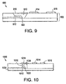
FIG. 9 is a side cross-sectional view of another supplementary embodiment of an amperometric sensor device. -
FIG. 10 is a side cross-sectional view of a supplementary embodiment of an amperometric sensor device. -
FIG. 11 is a side cross-sectional view of a supplementary embodiment of an amperometric sensor device. -
FIG. 12 is a side cross-sectional view of an embodiment of a potentiometric sensor device, not part of the invention as claimed. -
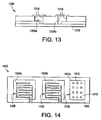
FIG. 13 is a side cross-sectional view of another embodiment of a potentiometric sensor device, not part of the invention as claimed. -
FIG. 14 is a top plan view of an embodiment of a conductometric sensor devices, not part of the invention as claimed. -
FIG. 15 is a top plan view of an embodiment of a conductometric sensor device, not part of the invention as claimed. - Electrochemical sensor devices are provided in packaging/configurations to address one or more of the needs described above. For example, sensor electrodes have been designed and arranged to improve sensor output, enhance sensor useful life, and permit reduced implant device dimensions.
- In one aspect, the present device, which may be a microchip package, is used to protect biosensors from exposure to adverse environments by encapsulating them within a reservoir or reservoirs until needed. In this way a continuous monitor can be constructed by utilizing the protected sensors in succession as their operational lifetimes are reached. The most straightforward approach to construction of the monitor is to contain each individual sensor within one reservoir. However, there may be reasons to consider different configurations where (i) the individual electrodes making up a sensor are not contained within the same reservoir, or (ii) a subset of the electrodes making up a sensor are not contained in a reservoir at all. These may be important for example when trying to reduce the size of an implanted sensing device.
- In certain embodiments, the electrochemical sensor devices include a structural body which comprises at least one reservoir, or more typically an array of two or more discrete reservoirs, each reservoir having at least one opening in the structural body; one or more of the electrodes of one or more chemical sensors located within the reservoir; at least one discrete reservoir cap closing the at least one opening of each reservoir to isolate the electrode(s) (and associated sensor chemistry, if present) that are located within the reservoir and to prevent external environmental components (e.g., an analyte) outside of the reservoir from contacting the electrode therein; and activation means for rupturing or displacing the reservoir cap to permit the external environmental components (e.g., an analyte) to contact the electrode. In exemplary embodiments, the discrete reservoir caps are in register with predefined openings in the structural body.
- In certain embodiments, the structural body (which sometimes may be referred to as the "substrate"), the reservoirs, the reservoir caps, and the activation means for rupturing or displacing the reservoir cap, and how these various components may be packaged together to form hermetically sealed reservoir devices, are described, for example, in
U.S. Patent No. 6,527,762 (which describes thermal means for reservoir cap rupture);U.S. Patent No. 6,551,838 ;U.S. Patent No. 6,976,982 (which describes flexible substrate/body structures);U.S. Patent No. 6,827,250 (which describes hermetic sealed reservoir structures and sealing methods);U.S. Patent Application Publication No. 2004/0121486 (which describes electrothermal ablation means for reservoir cap disintegration);U.S. Patent Application Publication No. 2006/0057737 (which describes reservoir/structural body designs with multiple discrete reservoir caps closing off a single reservoir opening);U.S. Patent Application Publication No. 2006/0115323 (which describes hermetic sealed reservoir structures and compression cold weld sealing methods); andU.S. Patent Application Publication No. 005/0096587 - In a certain embodiment, the reservoir cap is formed of a conductive material, such as a metal film, through which an electrical current can be passed to electrothermally ablate it, as described in
U.S. Patent Application Publication No. 2004/0121486 to Uhland, et al. In this embodiment, the reservoir cap itself serves both as a structural barrier for isolating the contents of the reservoir from substances outside of the reservoir and as the heating element. Representative examples of suitable reservoir cap materials include gold, copper, aluminum, silver, platinum, titanium, palladium, various alloys (e.g., Au/Si, Au/Ge, Pt--Ir, Ni--Ti, Pt--Si, SS 304, SS 316), and silicon doped with an impurity to increase electrical conductivity, as known in the art. The reservoir cap may be in the form of a multi-layer structure, such as a multi-layer/laminate structure of platinum/titanium/platinum. The reservoir cap is operably (i.e., electrically) connected to an electrical input lead and to an electrical output lead, to facilitate flow of an electrical current through the reservoir cap. When an effective amount of an electrical current is applied through the leads and reservoir cap, the temperature of the reservoir cap is locally increased due to resistive heating, and the heat generated within the reservoir cap increases the temperature sufficiently to cause the reservoir cap to be electrothermally ablated (ruptured or disintegrated). The heating may be rapid and substantially instantaneous upon application of an electric current through the reservoir cap, such that no substantial heating of substances (e.g., sensor chemistry, patient tissues) adjacent to the reservoir cap occurs. In one embodiment, the reservoir cap and the conductive leads are formed of the same material, and the temperature of the reservoir cap increases locally under applied current because the reservoir cap is suspended in a medium that is less thermally conductive than the substrate. Alternatively, the reservoir cap and conductive leads are formed of the same material, and the reservoir cap has a smaller cross-sectional area in the direction of electric current flow, where the increase in current density through the reservoir cap causes an increase in localized heating. The reservoir cap alternatively can be formed of a material that is different from the material forming the leads, wherein the material forming the reservoir cap has a different electrical resistivity, thermal diffusivity, thermal conductivity, and/or a lower melting temperature than the material forming the leads. Various combinations of these embodiments can be employed. For example, the reservoir cap and the input and output leads may be designed to provide (i) an increase in electrical current density in the reservoir cap relative to the current density in the input and output leads, upon the application of electrical current, (ii) that the material forming the reservoir cap has a different electrical resistivity, thermal diffusivity, thermal conductivity, and/or a lower melting temperature than the material forming the input and output leads, or (iii) both (i) and (ii). - In another embodiment, the reservoir cap is configured as an anode and the device further includes a cathode, along with electrical circuitry, a power source, and controls for applying an electric potential between the cathode and anode in an electrically conductive fluid environment (e.g., in vivo) to cause the reservoir cap to disintegrate as described in
U.S. Patent No. 5,797,898 to Santini Jr. et al. - In still another embodiment, the reservoir cap is configured to rupture by heating using a separate resistive heating element, which may be located either inside the reservoir or outside the reservoir, generally adjacent to the reservoir cap, as described for example in
U.S. Patent No. 6,527,762 to Santini Jr. et al. - The International Union of Pure and Applied Chemistry defines an electrochemical biosensor as "a self-contained integrated device, which is capable of providing specific quantitative or semi-quantitative analytical information using a biological recognition element (biochemical receptor) which is retained in direct spatial contact with an electrochemical transduction element." See Thevenot, et al., "Electrochemical Biosensors: Recommended Definitions And Classification", Pure App/. Chem., Vol. 71, No. 12, pp. 2333±2348, 1999. The present electrochemical biosensor devices can be classified as four types: amperometric, potentiometric, surface charge using field-effect transistors, and conductometric.
- The term "biosensor" as used herein is not to be construed as being limited to sensors for medical applications. The sensors device structures described herein may be useful in non-medical applications.
- Amperometric biosensors directly measure current produced by the oxidation or reduction of an electroactive species at a suitably polarized electrode. An amperometric biosensor can include three electrodes: a working electrode, a reference electrode, and an auxiliary electrode (sometimes referred to as a counter electrode). Suitable instrumentation is used to maintain the working electrode at a controlled potential relative to the reference electrode. In some cases, the amperometric biosensor is constructed with two electrodes where the functions of the reference electrode and the auxiliary electrode are combined. The biosensors' biological recognition element is often-though not in all embodiments an enzyme for which the analyte of interest is a biochemical substrate. Amperometric sensors exploit the fact that many co-substrates or products of the reaction catalyzed by the enzyme are electroactive. These sensors serve to measure the concentration of a co-substrate or product in the enzyme layer. In the presence of the analyte, the concentration of the co-substrate will decrease and that of the product will increase. The resulting change in sensor current can be related to the analyte concentration through a suitable calibration. Representative examples of suitable enzymes may include glucose oxidase, glucose dehydrogenase, NADH oxidase, uricase, urease, creatininase, sarcosine oxidase, creatinase, creatine kinase, creatine amidohydrolase, cholesterol esterase, cholesterol oxidase, glycerol kinase, hexokinase, glycerol-3-phosphate oxidase, lactate oxidase, lactate dehydrogenase, alkaline phosphatase, alanine transaminase, aspartate transaminase, amylase, lipase, esterase, gamma-glutamyl transpeptidase, L-glutamate oxidase, pyruvate oxidase, diaphorase, bilirubin oxidase, and mixtures thereof. An amperometric biosensor could be constructed without an enzyme layer, for example if the biosensor is configured to measure oxygen.
- It is believed that if certain embodiments of reservoir-device protected amperometric sensors were constructed in which the working and auxiliary electrodes are located inside the reservoir and the reference electrode is located outside of the reservoir, such a sensor may have operational difficulties. For example, there may be relatively high electrical impedance between the reference and working electrodes before the reservoir is opened due to a lack of fluid communication between the inside of an unopened reservoir and the surrounding environment, the distance from the reference electrode to the working electrode being considerably greater than from the auxiliary to working electrode, and the auxiliary and working electrodes both being located under the sensor chemistry. Accordingly, improved configurations are now provided as described herein.
- In these proposed new configurations, the amperometric sensor's working electrode is contained within a reservoir in order to protect the biological recognition element and other parts of the sensor chemistry from the in vivo environment, while the other electrodes, such as the reference and auxiliary electrodes, making up the sensor's electrochemical cell are variously located inside or outside of the same or different reservoirs as the working electrode, as described herein. In addition to an enzyme (or other biological recognition element) layer, the sensor chemistry typically includes one, two, three, or more polymer layers deposited over the working electrode effective to block interfering substances, to improve the linearity, range and specificity of the sensor, and in some cases, to modulate the properties (e.g., vascularity) of the sensor interface with surrounding tissue. Each layer may provide one or more of these functionalities.
- It is advantageous to contain the working electrode in a sealed reservoir for selective exposure (such as at the precise time the electrode is needed for a particular sensor to function) in order to protect the working electrode against (i) fouling of the outer layer of the sensor by proteins and cells which influence transport of analyte to the enzyme layer, (ii) degradation of the enzyme by the hydrogen peroxide produced by oxidase enzymes, (iii) degradation of polymer layers, for example, the hydrolysis of ester linkages of polyurethane membranes, and (iv) degradation processes mediated by cells of the immune system (e.g., macrophages, foreign body giant cells). In addition, hermetically sealed reservoirs enable the environment (e.g., inert gas atmosphere, humidity) inside the sealed reservoir to be controlled, which may lead to a longer lifetime of the sensor.
- In one embodiment, the amperometric sensor is a glucose biosensor based on the enzyme glucose oxidase. The enzyme-catalyzed conversion ofanalyte (e.g., glucose) yields a reaction product (e.g., hydrogen peroxide) that is redox active. (Alternatively, the catalytic activity of the enzyme may result in the consumption of a redox-active co-substrate, such as oxygen in the glucose sensor.) The oxidation or reduction of the redox active compound at a suitably polarized electrode produces a current that can be related back to the analyte concentration.
- In one embodiment, an amperometric sensor may be constructed with two electrodes. The same considerations apply as to placement of the working electrode and combined reference/auxiliary in the same or different reservoirs. In an embodiment, the electrodes may include elongated configurations, e.g., a "wire sensor", as described in
U.S. Patent No. 5,165,407 to Wilson et al. - The particular sensors packaged as described herein may take a variety of different forms. In some embodiments, the sensors are tailored for glucose sensing. In a certain embodiment, the present packaged sensor device may include electrodes and glucose sensor chemistries as described in
U.S. Patent No. 6,881,551 to Heller et al. or as described inU.S. Patent No. 4,890,620 to Gough et al. In other embodiments, the packaged sensor device may include a differential oxygen sensor, as described for example inU.S. Patent No. 4,781,798 . - In a preferred embodiment, the amperometric sensor utilizes three electrodes. The three electrode electrochemical "cell" has working, auxiliary and reference electrodes. The working electrode is where the desired analyte is oxidized or reduced, yielding the sensor current. The reference electrode is used to sense the potential in the solution; the external circuitry (potentiostat) establishes a fixed potential between the reference electrode and the working electrode. The reference electrode desirably is in close proximity to the working electrode to reduce any resistive (IR) potential drops, which may change the working electrode potential. The auxiliary electrode sinks or sources the working electrode current. The auxiliary electrode typically is equal in area to or larger in area than the working electrode in order to reduce the current density and overpotential at the auxiliary electrode.
- In certain embodiments of the present devices and methods, the working electrode is located within a reservoir that is sealed and can be selectively unsealed or opened. In a preferred embodiment, the working and reference electrodes are both protected by locating them within one or more reservoirs. This may be a preferred configuration for an implantable sensor device. The reference electrode may be in close proximity to the working electrode and may be protected from environmental degradation by the reservoir cap.
- The working electrode in the reservoir includes, e.g., is covered completely or at least partially by, an appropriate analyte sensor chemistry. The reference electrode may or may not be covered by the sensor chemistry. In one embodiment, it may be preferable or simpler to deposit the chemistry over both electrodes, and in this way the reference electrode may be considered to be measuring the environment seen by the working electrode. However this may not be desirable for certain embodiments where the composition of the reference electrode is such that it reacts or interferes with sensor chemistry. For example, silver ions from a silver/silver chloride reference electrode may inhibit glucose oxidase activity. In such embodiments, the sensor chemistry preferably is applied to cover only the working electrode. It can facilitate depositing a sensor chemistry over an electrode to first surround the electrode with a barrier as conventionally known, for example, as shown in
U.S. Patent No. 5,376,255 to Gumbrecht, et al. - The nature and placement of the auxiliary electrode outside of the reservoir may be varied. For example, it may be located on a lower substrate portion, coplanar with the working and reference electrodes, or it could be on a surface of an upper substrate portion. (The term "upper substrate portion" as used herein may be referred to in the art as a "microchip" or "microchip portion," as this substrate may include electronic circuitry for operation/actuation of reservoir cap disintegration.) In one embodiment, the portions of the reservoir caps remaining after activation, e.g., following electrothermal ablation, and the electrical traces connecting to the reservoir caps may be utilized as the auxiliary electrode. In another embodiment, as shown in
FIG. 4 , the auxiliary electrode is located on a surface of the upper substrate portion of the reservoir device, but is electrically isolated from the reservoir caps or traces connected to the reservoir caps. In yet another embodiment, an auxiliary electrode "external" to the sensor and reservoir substrates, such as a wire lead or the electronics case may be used. It may be advantageous to locate the auxiliary electrode outside of the reservoir, to minimize the interaction between redox reactions occurring at the auxiliary electrode and reactions taking place at the working electrode. A reason to separate the electrodes is that oxygen may be consumed at the auxiliary electrode which may otherwise limit the amount of oxygen available in the enzyme layer at the working electrode for glucose oxidation. - In another embodiment, the reference electrode and the working electrode are provided in separate reservoirs. This may be less desirable from the standpoint of having the reference electrode close to the working electrode, but may be desirable where the lifetime of the reference electrode is considerably greater than the working electrode, such that a single reference electrode could be used with a succession of working electrodes. In one embodiment, a single reference electrode (and a single auxiliary electrode) may be used with a two working electrodes operating simultaneously, in a configuration under control of a bipotentiostat. In another embodiment, a single reference electrode (and a single auxiliary electrode) may be used with more than two working electrodes operating simultaneously. Similarly, one auxiliary electrode may be used with more than one working electrode.
- Examples of various embodiments of the amperometric sensor devices are illustrated in
FIGS. 1-11 . These are not drawn to scale. The shapes and dimensions of the electrodes, the reservoirs, the reservoir openings, the sensor chemistries, the substrates, and the bonding layers, if any, may be varied as needed to accommodate device specifications and manufacturing design constraints. It is to be understood from the figures that show only a single reservoir, that, in certain embodiments, a sensor device would include a structural body comprising an array of multiple such representative reservoirs/sensors. -
FIG. 1 shows one embodiment of anamperometric sensor device 100. Thedevice 100 generally includes a structural body orsubstrate 102. In the illustrated embodiment, thestructural body 102 includes a lower substrate portion orbase layer 104, an intermediate substrate portion orbonding layer 106, and anupper substrate portion 108. Areservoir 110 is formed in thesubstrate 102. Although only onereservoir 110 is shown, an array ofreservoirs 110 may be provided. Thesereservoirs 110 may be, for example, identical and discrete, although other configurations are possible. - The
amperometric sensor device 100 also includes a workingelectrode 112, areference electrode 114, and anauxiliary electrode 116. As shown, the workingelectrode 112 and thereference electrode 114 are disposed within thereservoir 110, and theauxiliary electrode 116 is provided outside of thereservoir 110. Areservoir cap 118 covers an opening in thereservoir 110. Thereservoir cap 118 may be electrically conductive, and traces or leads 120 may be provided for directing electric current through thereservoir cap 118. In the illustrated embodiment, the traces or leads 120 may serve as theauxiliary electrode 116 to conserve space. Such a configuration may require the ability to switch the connection of thereservoir cap 118 and traces or leads 120 from the reservoir cap activation electronics to the sensor electronics, but other configurations are possible. - The
device 100 further includessensor chemistry 122 located in thereservoir 110. Thesensor chemistry 122 may include, for example, an enzyme and one or more polymer layers, such as those useful as semi-permeable membranes to permit passage of an analyte of interest therethrough while excluding certain other molecules. As shown, thesensor chemistry 122 may be deposited on both the workingelectrode 112 and thereference electrode 114, so that thereference electrode 114 is exposed to (i.e. "sees") the same environment as the workingelectrode 112, although in other embodiments thesensor chemistry 122 may not be deposited on thereference electrode 114. - The
amperometric sensor device 100 also includes power and control systems (not shown) that power and control disintegration of thereservoir cap 118 and operatively couple to the electrodes. The power and control systems may be provided in a hardwired or wireless manner, for example, as described inU.S. Patent No. 7,226,442 andU.S. Patent Application Publication No. 2005/0096587 . - The illustrated embodiment of the
device 100 includes a single set ofelectrodes single reservoir 102, forming a sensor. In other embodiments, thedevice 100 may include an array ofreservoirs 110. For example, thedevice 100 may include a number of identical,discrete reservoirs 110 that may be opened sequentially, such as one at a time, as a preceding exposed sensor becomes fouled and a fresh sensor is needed. -
FIG. 2 shows supplementary alternative embodiment of anamperometric sensor device 200, in which the workingelectrode 212 and thereference electrode 214 are located in asingle reservoir 210, but theauxiliary electrode 216, which is outside of thereservoir 210, is a separate structural component from thereservoir cap 218 and its traces or leads 220. In certain cases, this may be a preferred embodiment, for example, in order to protect both the workingelectrode 212 and thereference electrode 214 inside thereservoir 210, or to position thereference electrode 214 and the workingelectrode 212 in close proximity to one another for operational purposes (e.g., so that they experience the same local microenvironment following reservoir opening) or to achieve both of these objectives. Note that inFIG. 2 , thesensor chemistry 222 is not deposited on thereference electrode 214, although other configurations are possible. In this embodiment, the sidewalls of the reservoir taper toward the reservoir opening/reservoir cap. The material used for the upper substrate portion and the preferred means of creating the reservoir within that material may influence the slope of the sidewalls. For example , deep reactive ion etching (DRIE) of silicon produces vertical reservoir sidewalls. -
FIG. 3 shows supplementary embodiments of anamperometric sensor device 300, which is a particular variation of thedevice 200 shown inFIG. 2 . As shown, thereservoir cap 318 may have a different composition than the traces or leads 320 connected to thereservoir cap 318. -
FIG. 4 shows another complementary embodiment of theamperometric sensor device 400. The structural body orsubstrate 402 includes theportions structural body 402 adjacent to each other. Specifically, a workingelectrode reservoir 410A is provided for the workingelectrode 412, while areference electrode reservoir 410B is provided for thereference electrode 414. In this embodiment, thesensor chemistry 422 is deposited on the workingelectrode 412 in the workingelectrode reservoir 410A, and one ormore polymer layers 423 are deposited on thereference electrode 414 in thereference electrode reservoir 410B. The polymer layers 423 may or may not be formed from similar components as thesensor chemistry 422, so that thereference electrode 414 in thereference electrode reservoir 410B is exposed to a similar environment as the workingelectrode 412 in the workingelectrode reservoir 410A. - The
auxiliary electrode 416 is positioned outside of the reservoirs 410. For example, theauxiliary electrode 416 may be located on anouter surface 424 of theupper substrate portion 408, between the workingelectrode reservoir 410A and thereference electrode reservoir 410B, so that theauxiliary electrode 416 is in operable proximity to the workingelectrode 412 and/orreference electrode 414. The working, reference, and auxiliary electrodes in use are in intimate contact with the body fluid such that there is a path of relatively low electrical resistance between them. Traces or leads may be connected to the reservoir cap 418 in some embodiments, although the traces or leads are not shown in FIG. - 4.
FIG. 5 illustrates yet another supplementary embodiment of theamperometric sensor device 500. As shown, the structural body orsubstrate 502 includes theportions reservoir 510 is formed in thestructural body 502. The workingelectrode 512 and thesensor chemistry 522 are located in thereservoir 510, while thereference electrode 514 and theauxiliary electrode 516 are located outside of thereservoir 510 on the same side of thestructural body 502 as thereservoir cap 518. -
FIG. 6 illustrates another supplementary embodiment of anamperometric sensor device 600. A number of reservoirs 610, such as three reservoirs 610A, 610B, and 610C, are formed in the structural body 602. A workingelectrode 612 andsensor chemistry 622 are located in each reservoir 610, whilereference electrodes 614 andauxiliary electrodes 616 are located outside of the reservoirs 610. As shown, there does not need to be a one-to-one correspondence between the number ofauxiliary electrodes 616 orreference electrodes 614 and the number of reservoirs 610. That is, two or more reservoirs 610 could share anauxiliary electrode 616, areference electrode 614 or both. -
FIG. 7 shows a supplementary embodiment of anamperometric sensor device 700 having an array of reservoirs, such as three reservoirs 710A, 710B, and 710C. Each reservoirs 710 contains a workingelectrode 712, areference electrode 714, and sensor chemistry.Auxiliary electrodes 716 are provided outside of the reservoirs 710, such as between adjacent reservoirs 710. For example, oneauxiliary electrode 716 is provided between reservoir 710A and reservoir 710B, and anotherauxiliary electrode 716 is provided between reservoir 710B and reservoir 710C. The auxiliary electrodes are positioned on the lower substrate portion orbase layer 704. Anupper substrate portion 708 is positioned above each reservoir 710. Note that for illustrative purposes theupper substrate portion 708 is shown over reservoir 710A, concealing the reservoir contents, while theupper substrate portion 708 is not shown over the remaining reservoirs 710B, 710C so that the reservoir contents can be seen (although the sensor chemistry is omitted for clarity). - The
upper substrate portion 708 includes an array of apertures that serve as reservoir openings. A series of discrete reservoir caps 718 close the reservoir openings to seal in the workingelectrode 712, thereference electrode 714, and the sensor chemistry. For the purpose of example, a 4 x 5 array of apertures and twenty corresponding discrete reservoir caps are shown here. The seal formed by the reservoir caps 718 may be hermetic. - An example of the
upper substrate portion 708 andreservoir cap 718 structure is described inU.S. Patent Application Publication No. 2006/0057737 , which is incorporated herein by reference. In this way, an individual reservoir may have at least two reservoir openings with a support structure therebetween and closed by two or more reservoir caps covering the openings to control exposure of the electrode(s) within that reservoir. In one embodiment, the substrate comprises at least one reservoir cap support extending over the reservoir contents, wherein the two or more reservoir caps are in part supported by the at least one reservoir cap support. In one embodiment, a sensor device may comprise an array of two or more of such reservoirs, each having multiple reservoir openings. The reservoir cap supports can comprise substrate material, structural material, or coating material, or combinations thereof. The reservoir cap support(s) may be integral with upper substrate portion. Alternatively, the reservoir cap support may be made from a coating or deposited material distinct from the substrate portion. Reservoir cap supports comprising substrate material may be formed in the same step as the reservoirs. MEMS methods, microfabrication, micromolding, and micromachining techniques described herein or known in the art may be used to fabricate the substrate/reservoirs, as well as reservoir cap supports, from a variety of substrate materials. -
FIG. 8 shows a supplementary embodiment of anamperometric sensor device 800 having an array of reservoirs 810, such as three reservoirs 810A, 810B, and 810C. Each reservoirs 810 contains a workingelectrode 812 and sensor chemistry (not shown). At least onereference electrode 814 and at least oneauxiliary electrode 816 are provided outside of the reservoirs 810, such as between adjacent reservoirs 810. These may be shared. For example, onereference electrode 814 and oneauxiliary electrode 816 are provided between reservoir 810A and reservoir 810B, which may shared by the working electrodes in these reservoirs 810A, 810B. -
FIG. 9 shows a supplementary embodiment of anamperometric sensor device 900 having the workingelectrode 912 and thesensor chemistry 922 located in thereservoir 910, and thereference electrode 914 and theauxiliary electrode 916 located outside of thereservoir 910. For example, thereference electrode 914 and theauxiliary electrode 916 may be located on the same side of thedevice 900 as thereservoir cap 918. Because resistive potential drops can be reduced by placing the workingelectrode 912 in close proximity to thereference electrode 914, the electrodes may be positioned so that the workingelectrode 912 is relatively closer to thereference electrode 914 than theauxiliary electrode 916.FIG. 10 shows anamperometric sensor device 1000 that is a variation of thedevice 900 shown inFIG. 9 . Like thedevice 900, the workingelectrode 1012 and thesensor chemistry 1022 are located in thereservoir 1010, and thereference electrode 1014 and theauxiliary electrode 1016 are located outside of thereservoir 1010. Thereservoir 1010 has sidewalls 1026 that are substantially perpendicular to the plane of the lower substrate portion orbase layer 1004.Such reservoirs 1010 may be made using techniques described for example inU.S. Patent Application Publication No. 2006/0105275 to Maloney et al. An intermediate substrate portion or bonding layer is not shown inFIG.10 , although it is contemplated that such a layer could be included in this embodiment. -
FIG. 11 shows another supplementary embodiment of anamperometric sensor device 1100. The structural body orsubstrate 1102 includes theportions reservoir 1110 is formed in thestructural body 1102. The workingelectrode 1112, thereference electrode 1114, and thesensor chemistry 1122 are located in thereservoir 1110, and theauxiliary electrode 1116 is provided outside of thereservoir 1110. In this embodiment, which may be referred to as a "flip chip" design, theleads 1120 and other circuitry for thereservoir cap 1118 are located between theintermediate substrate portion 1106 and theupper substrate portion 1108, such that they are protected. Theauxiliary electrode 1116 may be provided on theouter surface 1124 of theupper substrate portion 1108, distal to thereservoir cap 1118 and the associated leads 1120. - Although a single reservoir is shown in several of the embodiments described above and illustrated in the appended drawings, it is understood that the sensor device may include an array of multiple reservoirs, such as, two, four, ten, twenty, or one hundred reservoirs, each reservoir being associated with a discrete or shared combination of electrodes to form a sensor. Likewise, other combinations of substrate structures, reservoir shapes/sidewall angles, reservoir cap disintegration means, and the like, besides the particular combinations illustrated and described herein, are contemplated.
- It is also understood that the sensor devices described herein may be used as or adapted for inclusion in non-medical devices and systems. For example, the sensors may be used as environmental sensors, which may have a number of particular applications. In one case, the devices may be used to sense heavy metals or other pollutants in bodies of water, such as lakes and streams. In another case, the devices may be used to detect biological weapon agents. Such devices could be adapted to be fixed or mobile, for use in public venues, as a wearable device on first responders, in public transit systems, airports, on military vehicles, etc.
- To the extent that any meaning or definition of a term in this document conflicts with any meaning or definition of the same term in a document cited in the present description, the meaning or definition assigned to that term in this document shall govern.
- Modifications and variations of the methods and devices described herein will be obvious to those skilled in the art from the foregoing detailed description. Such modifications and variations are intended to come within the scope of the appended claims.
Claims (10)
- An amperometric sensor device (100, 500) comprising:a structural body (102, 502) which comprises at least one reservoir (110, 510) that has at least one opening in the structural body;a working electrode (112, 512) located within the reservoir (110, 510);analyte sensor chemistry (122, 522) located within the reservoir (110, 510) and deposited on at least the working electrode (112, 512);an auxiliary electrode and a reference electrode;at least one reservoir cap (118, 518) closing the at least one opening to isolate the working electrode (112, 512) and analyte sensor chemistry (122, 522) within the reservoir and to prevent an analyte outside of the reservoir (110, 510) from contacting the analyte sensor chemistry; andmeans (120, 220, 320, 1120) for rupturing or displacing the reservoir cap to permit the analyte from outside of the reservoir to contact the analyte sensor chemistry;characterized in that the auxiliary electrode (116, 216, 416, 716, 1116) is located on the structural body outside of the reservoir and the reference electrode (114, 214, 414, 714, 1114) is located inside the reservoir, or the auxiliary electrode (516, 616, 816, 916, 1016) is located on the structural body outside of any reservoir and the reference electrode (514, 614, 814, 914, 1014) is located outside of any reservoir,
wherein the means for rupturing or displacing comprises:a pair of conductive leads (120, 220, 320, 1120) electrically connected to the reservoir cap, the reservoir cap comprising an electrically conductive material; anda power source for applying an electrical current through the reservoir cap, via the pair of conductive leads,wherein the pair of conductive leads and power source are adapted to rupture the reservoir cap by electrothermal ablation,
and wherein the pair of conductive leads (120), the reservoir cap (118), or both, serve as the auxiliary electrode (116). - The amperometric sensor device of claim 1, wherein the analyte sensor chemistry (122, 1122) is further deposited on the reference electrode (114, 1114).
- The amperometric sensor device of claim 1, wherein the reference electrode (414) is located in a second reservoir which is separate from the reservoir containing the working electrode.
- The amperometric sensor device of claim 1, wherein the area of the auxiliary electrode is equal to or larger than the area of the working electrode.
- The amperometric sensor device of any one of claims 1 to 4, wherein the analyte sensor chemistry (122, 522) comprises an enzyme-containing layer and at least one polymer layer.
- The amperometric sensor device of claim 5, wherein the enzyme is selected from the group consisting of glucose oxidase, glucose dehydrogenase, NADH oxidase, uricase, urease, creatininase, sarcosine oxidase, creatinase, creatine kinase, creatine amidohydrolase, cholesterol esterase, cholesterol oxidase, glycerol kinase, hexokinase, glycerol-3-phosphate oxidase, lactate oxidase, lactate dehydrogenase, alkaline phosphatase, alanine transaminase, aspartate transaminase, amylase, lipase, esterase, gamma-glutamyl transpeptidase, L-glutamate oxidase, pyruvate oxidase, diaphorase, bilirubin oxidase, and mixtures thereof.
- The amperometric sensor device of any one of claims 1 to 6, which comprises a plurality of the reservoirs (601a, 610b, 610c; 710a, 710b, 710c; 810 a, 810b, 810c), a plurality of the working electrodes (612, 712, 812) and the analyte sensor chemistries (622) located correspondingly therein, and a plurality of the at least one reservoir caps (618, 718, 818) closing openings in the reservoirs, wherein the reference electrode (614, 814), the auxiliary electrode (716, 816), or both, are adapted to be operatively coupled with two or more of the plurality of the working electrodes (612, 712, 812).
- The amperometric sensor device of any one of claims 1 to 7, wherein the reservoir (710a, 810a) has two or more openings and two or more discrete reservoir caps (718, 818), each reservoir cap closing at least one of the reservoir openings, and wherein the structural body further comprises at least one reservoir cap support extending over the reservoir, wherein the two or more reservoir caps are in part supported by the at least one reservoir cap support.
- An implantable medical device comprising the amperometric sensor device of any one of claims 1 to 8.
- A catheter comprising the amperometric sensor device of any one of claims 1 to 8.
Priority Applications (1)
| Application Number | Priority Date | Filing Date | Title |
|---|---|---|---|
| EP12160400A EP2471457A1 (en) | 2007-06-07 | 2008-06-06 | Electrochemical biosensors and arrays |
Applications Claiming Priority (2)
| Application Number | Priority Date | Filing Date | Title |
|---|---|---|---|
| US94259407P | 2007-06-07 | 2007-06-07 | |
| PCT/US2008/066172 WO2008154416A2 (en) | 2007-06-07 | 2008-06-06 | Electrochemical biosensors and arrays |
Related Child Applications (1)
| Application Number | Title | Priority Date | Filing Date |
|---|---|---|---|
| EP12160400.3 Division-Into | 2012-03-20 |
Publications (2)
| Publication Number | Publication Date |
|---|---|
| EP2157907A2 EP2157907A2 (en) | 2010-03-03 |
| EP2157907B1 true EP2157907B1 (en) | 2013-03-27 |
Family
ID=39718948
Family Applications (2)
| Application Number | Title | Priority Date | Filing Date |
|---|---|---|---|
| EP08770378A Not-in-force EP2157907B1 (en) | 2007-06-07 | 2008-06-06 | Electrochemical biosensors and arrays |
| EP12160400A Withdrawn EP2471457A1 (en) | 2007-06-07 | 2008-06-06 | Electrochemical biosensors and arrays |
Family Applications After (1)
| Application Number | Title | Priority Date | Filing Date |
|---|---|---|---|
| EP12160400A Withdrawn EP2471457A1 (en) | 2007-06-07 | 2008-06-06 | Electrochemical biosensors and arrays |
Country Status (3)
| Country | Link |
|---|---|
| US (1) | US8649840B2 (en) |
| EP (2) | EP2157907B1 (en) |
| WO (1) | WO2008154416A2 (en) |
Families Citing this family (78)
| Publication number | Priority date | Publication date | Assignee | Title |
|---|---|---|---|---|
| US7749766B2 (en) * | 2007-01-12 | 2010-07-06 | Nova Biomedical Corporation | Bilirubin sensor |
| CN102006822B (en) * | 2008-04-18 | 2015-01-21 | 西门子公司 | Endocapsule |
| GR1007310B (en) * | 2009-03-09 | 2011-06-10 | Αχιλλεας Τσουκαλης | Implantable biosensor with automatic calibration |
| CN102449468B (en) * | 2009-03-26 | 2014-02-26 | 独立行政法人物质·材料研究机构 | Sensor for detecting material to be tested |
| WO2011018407A1 (en) * | 2009-08-08 | 2011-02-17 | Sanofi-Aventis Deutschland Gmbh | Implantable sensor device and medical delivery device connectable to such a sensor device |
| EP2496936B1 (en) * | 2009-10-16 | 2018-02-21 | Microchips Biotech, Inc. | Multi-channel potentiostat for biosensor arrays and method of operation |
| US9288089B2 (en) | 2010-04-30 | 2016-03-15 | Ecole Polytechnique Federale De Lausanne (Epfl) | Orthogonal differential vector signaling |
| US9450744B2 (en) | 2010-05-20 | 2016-09-20 | Kandou Lab, S.A. | Control loop management and vector signaling code communications links |
| US8593305B1 (en) | 2011-07-05 | 2013-11-26 | Kandou Labs, S.A. | Efficient processing and detection of balanced codes |
| US9288082B1 (en) | 2010-05-20 | 2016-03-15 | Kandou Labs, S.A. | Circuits for efficient detection of vector signaling codes for chip-to-chip communication using sums of differences |
| US9251873B1 (en) | 2010-05-20 | 2016-02-02 | Kandou Labs, S.A. | Methods and systems for pin-efficient memory controller interface using vector signaling codes for chip-to-chip communications |
| US9985634B2 (en) | 2010-05-20 | 2018-05-29 | Kandou Labs, S.A. | Data-driven voltage regulator |
| US9246713B2 (en) | 2010-05-20 | 2016-01-26 | Kandou Labs, S.A. | Vector signaling with reduced receiver complexity |
| US9077386B1 (en) | 2010-05-20 | 2015-07-07 | Kandou Labs, S.A. | Methods and systems for selection of unions of vector signaling codes for power and pin efficient chip-to-chip communication |
| EP2608715B1 (en) * | 2010-08-24 | 2016-06-22 | Microchips, Inc. | Implantable biosensor device and methods of use thereof |
| EP2438860A1 (en) | 2010-10-07 | 2012-04-11 | BIOTRONIK SE & Co. KG | Medical sensor system |
| US9687182B2 (en) | 2010-10-07 | 2017-06-27 | Biotronik Se & Co. Kg | Medical sensor system for detecting a feature in a body |
| US9275720B2 (en) | 2010-12-30 | 2016-03-01 | Kandou Labs, S.A. | Differential vector storage for dynamic random access memory |
| US10427153B2 (en) | 2011-08-25 | 2019-10-01 | Microchips Biotech, Inc. | Systems and methods for sealing a plurality of reservoirs of a microchip element with a sealing grid |
| CN107049243A (en) | 2011-08-25 | 2017-08-18 | 微芯片生物科技公司 | Space-efficient locking device and its manufacture method |
| US9268683B1 (en) | 2012-05-14 | 2016-02-23 | Kandou Labs, S.A. | Storage method and apparatus for random access memory using codeword storage |
| SG11201504886SA (en) | 2012-12-21 | 2015-07-30 | Microchips Biotech Inc | Implantable medical device for minimally-invasive insertion |
| AU2014214800A1 (en) | 2013-02-06 | 2015-08-06 | California Institute Of Technology | Miniaturized implantable electrochemical sensor devices |
| CN105122758B (en) | 2013-02-11 | 2018-07-10 | 康杜实验室公司 | High bandwidth interchip communication interface method and system |
| EP2961466B1 (en) | 2013-02-28 | 2018-12-19 | Microchips Biotech, Inc. | Implantable medical device for minimally-invasive insertion |
| WO2014164654A1 (en) | 2013-03-11 | 2014-10-09 | The University Of Toledo | A biosensor device to target analytes in situ, in vivo, and/or in real time, and methods of making and using the same |
| EP2979388B1 (en) | 2013-04-16 | 2020-02-12 | Kandou Labs, S.A. | Methods and systems for high bandwidth communications interface |
| US9806761B1 (en) | 2014-01-31 | 2017-10-31 | Kandou Labs, S.A. | Methods and systems for reduction of nearest-neighbor crosstalk |
| CN105993151B (en) | 2014-02-02 | 2019-06-21 | 康杜实验室公司 | Low ISI is than low-power interchip communication method and apparatus |
| WO2015131203A1 (en) | 2014-02-28 | 2015-09-03 | Kandou Lab, S.A. | Clock-embedded vector signaling codes |
| ES2686218T3 (en) | 2014-04-07 | 2018-10-16 | Tubitak | An electrochemical sensor distribution device |
| US9509437B2 (en) | 2014-05-13 | 2016-11-29 | Kandou Labs, S.A. | Vector signaling code with improved noise margin |
| US9148087B1 (en) | 2014-05-16 | 2015-09-29 | Kandou Labs, S.A. | Symmetric is linear equalization circuit with increased gain |
| US9513184B2 (en) * | 2014-06-11 | 2016-12-06 | Ams International Ag | MEMS device calibration |
| US9112550B1 (en) | 2014-06-25 | 2015-08-18 | Kandou Labs, SA | Multilevel driver for high speed chip-to-chip communications |
| CN106797352B (en) | 2014-07-10 | 2020-04-07 | 康杜实验室公司 | High signal-to-noise characteristic vector signaling code |
| US9432082B2 (en) | 2014-07-17 | 2016-08-30 | Kandou Labs, S.A. | Bus reversable orthogonal differential vector signaling codes |
| KR101943048B1 (en) | 2014-07-21 | 2019-01-28 | 칸도우 랩스 에스에이 | Multidrop data transfer |
| CN106576087B (en) | 2014-08-01 | 2019-04-12 | 康杜实验室公司 | Orthogonal differential vector signaling code with embedded clock |
| US9674014B2 (en) | 2014-10-22 | 2017-06-06 | Kandou Labs, S.A. | Method and apparatus for high speed chip-to-chip communications |
| US10376145B2 (en) | 2015-02-24 | 2019-08-13 | Elira, Inc. | Systems and methods for enabling a patient to achieve a weight loss objective using an electrical dermal patch |
| US10864367B2 (en) | 2015-02-24 | 2020-12-15 | Elira, Inc. | Methods for using an electrical dermal patch in a manner that reduces adverse patient reactions |
| US10765863B2 (en) | 2015-02-24 | 2020-09-08 | Elira, Inc. | Systems and methods for using a transcutaneous electrical stimulation device to deliver titrated therapy |
| US10335302B2 (en) | 2015-02-24 | 2019-07-02 | Elira, Inc. | Systems and methods for using transcutaneous electrical stimulation to enable dietary interventions |
| US9956393B2 (en) | 2015-02-24 | 2018-05-01 | Elira, Inc. | Systems for increasing a delay in the gastric emptying time for a patient using a transcutaneous electro-dermal patch |
| US20220062621A1 (en) | 2015-02-24 | 2022-03-03 | Elira, Inc. | Electrical Stimulation-Based Weight Management System |
| CN115227969A (en) | 2015-02-24 | 2022-10-25 | 伊莱拉股份有限公司 | Method for achieving appetite regulation or improving dietary compliance using electrode patches |
| GB2538724A (en) * | 2015-05-26 | 2016-11-30 | Imp Innovations Ltd | Methods |
| GB2539224A (en) * | 2015-06-09 | 2016-12-14 | Giuseppe Occhipinti Luigi | Method of forming a chemical sensor device and device |
| US9798886B2 (en) | 2015-07-08 | 2017-10-24 | International Business Machines Corporation | Bio-medical sensing platform |
| US10368788B2 (en) * | 2015-07-23 | 2019-08-06 | California Institute Of Technology | System and methods for wireless drug delivery on command |
| US9557760B1 (en) | 2015-10-28 | 2017-01-31 | Kandou Labs, S.A. | Enhanced phase interpolation circuit |
| US9577815B1 (en) | 2015-10-29 | 2017-02-21 | Kandou Labs, S.A. | Clock data alignment system for vector signaling code communications link |
| KR102540664B1 (en) * | 2015-11-03 | 2023-06-08 | 삼성전자주식회사 | Bio sensor and sensing method thereof |
| US10055372B2 (en) | 2015-11-25 | 2018-08-21 | Kandou Labs, S.A. | Orthogonal differential vector signaling codes with embedded clock |
| WO2017132292A1 (en) | 2016-01-25 | 2017-08-03 | Kandou Labs, S.A. | Voltage sampler driver with enhanced high-frequency gain |
| CN109314518B (en) | 2016-04-22 | 2022-07-29 | 康杜实验室公司 | High performance phase locked loop |
| US10003454B2 (en) | 2016-04-22 | 2018-06-19 | Kandou Labs, S.A. | Sampler with low input kickback |
| CN109417521B (en) | 2016-04-28 | 2022-03-18 | 康杜实验室公司 | Low power multi-level driver |
| EP3449379B1 (en) | 2016-04-28 | 2021-10-06 | Kandou Labs S.A. | Vector signaling codes for densely-routed wire groups |
| US10153591B2 (en) | 2016-04-28 | 2018-12-11 | Kandou Labs, S.A. | Skew-resistant multi-wire channel |
| US10620151B2 (en) | 2016-08-30 | 2020-04-14 | Analog Devices Global | Electrochemical sensor, and a method of forming an electrochemical sensor |
| US11268927B2 (en) | 2016-08-30 | 2022-03-08 | Analog Devices International Unlimited Company | Electrochemical sensor, and a method of forming an electrochemical sensor |
| US9906358B1 (en) | 2016-08-31 | 2018-02-27 | Kandou Labs, S.A. | Lock detector for phase lock loop |
| US10736565B2 (en) | 2016-10-14 | 2020-08-11 | Eccrine Systems, Inc. | Sweat electrolyte loss monitoring devices |
| EP3364183A1 (en) * | 2017-02-21 | 2018-08-22 | Eccrine Systems, Inc. | Sweat electrolyte loss monitoring devices |
| US11733197B2 (en) * | 2017-05-04 | 2023-08-22 | Siemens Healthcare Diagnostics Inc. | Biosensors produced from enzymes with reduced solubility and methods of production and use thereof |
| WO2019050633A2 (en) * | 2017-07-24 | 2019-03-14 | California Institute Of Technology | Low power, chemically amplified, electrically removable barrier |
| US10324097B2 (en) | 2017-08-30 | 2019-06-18 | NeoLight LLC | System and methods for bilirubin analysis |
| US10739302B2 (en) | 2017-11-02 | 2020-08-11 | International Business Machines Corporation | Bio and chemical sensor with increased sensitivity |
| US11022579B2 (en) | 2018-02-05 | 2021-06-01 | Analog Devices International Unlimited Company | Retaining cap |
| US11636870B2 (en) | 2020-08-20 | 2023-04-25 | Denso International America, Inc. | Smoking cessation systems and methods |
| US11881093B2 (en) | 2020-08-20 | 2024-01-23 | Denso International America, Inc. | Systems and methods for identifying smoking in vehicles |
| US11760170B2 (en) | 2020-08-20 | 2023-09-19 | Denso International America, Inc. | Olfaction sensor preservation systems and methods |
| US11828210B2 (en) | 2020-08-20 | 2023-11-28 | Denso International America, Inc. | Diagnostic systems and methods of vehicles using olfaction |
| US11760169B2 (en) | 2020-08-20 | 2023-09-19 | Denso International America, Inc. | Particulate control systems and methods for olfaction sensors |
| US11813926B2 (en) | 2020-08-20 | 2023-11-14 | Denso International America, Inc. | Binding agent and olfaction sensor |
| US11932080B2 (en) | 2020-08-20 | 2024-03-19 | Denso International America, Inc. | Diagnostic and recirculation control systems and methods |
Citations (1)
| Publication number | Priority date | Publication date | Assignee | Title |
|---|---|---|---|---|
| WO2005073705A1 (en) * | 2004-01-29 | 2005-08-11 | Siemens Aktiengesellschaft | Electrochemical transducer array and the use thereof |
Family Cites Families (76)
| Publication number | Priority date | Publication date | Assignee | Title |
|---|---|---|---|---|
| US4781798A (en) | 1985-04-19 | 1988-11-01 | The Regents Of The University Of California | Transparent multi-oxygen sensor array and method of using same |
| US4890620A (en) | 1985-09-20 | 1990-01-02 | The Regents Of The University Of California | Two-dimensional diffusion glucose substrate sensing electrode |
| US4703756A (en) * | 1986-05-06 | 1987-11-03 | The Regents Of The University Of California | Complete glucose monitoring system with an implantable, telemetered sensor module |
| US4874500A (en) | 1987-07-15 | 1989-10-17 | Sri International | Microelectrochemical sensor and sensor array |
| US5252294A (en) | 1988-06-01 | 1993-10-12 | Messerschmitt-Bolkow-Blohm Gmbh | Micromechanical structure |
| US5200051A (en) | 1988-11-14 | 1993-04-06 | I-Stat Corporation | Wholly microfabricated biosensors and process for the manufacture and use thereof |
| US5165407A (en) | 1990-04-19 | 1992-11-24 | The University Of Kansas | Implantable glucose sensor |
| US5493177A (en) | 1990-12-03 | 1996-02-20 | The Regents Of The University Of California | Sealed micromachined vacuum and gas filled devices |
| US5254081A (en) | 1991-02-01 | 1993-10-19 | Empi, Inc. | Multiple site drug iontophoresis electronic device and method |
| US5593852A (en) | 1993-12-02 | 1997-01-14 | Heller; Adam | Subcutaneous glucose electrode |
| US5605662A (en) | 1993-11-01 | 1997-02-25 | Nanogen, Inc. | Active programmable electronic devices for molecular biological analysis and diagnostics |
| US5262127A (en) | 1992-02-12 | 1993-11-16 | The Regents Of The University Of Michigan | Solid state chemical micro-reservoirs |
| US5304293A (en) | 1992-05-11 | 1994-04-19 | Teknekron Sensor Development Corporation | Microsensors for gaseous and vaporous species |
| DE59304876D1 (en) | 1992-09-14 | 1997-02-06 | Siemens Ag | Gas sensor |
| US6256522B1 (en) | 1992-11-23 | 2001-07-03 | University Of Pittsburgh Of The Commonwealth System Of Higher Education | Sensors for continuous monitoring of biochemicals and related method |
| US5366454A (en) | 1993-03-17 | 1994-11-22 | La Corporation De L'ecole Polytechnique | Implantable medication dispensing device |
| PT725682E (en) | 1993-10-28 | 2002-09-30 | Houston Advanced Res Ct | POROSO MICROFABRICATED DRAIN DEVICE |
| US5798042A (en) | 1994-03-07 | 1998-08-25 | Regents Of The University Of California | Microfabricated filter with specially constructed channel walls, and containment well and capsule constructed with such filters |
| IE72524B1 (en) * | 1994-11-04 | 1997-04-23 | Elan Med Tech | Analyte-controlled liquid delivery device and analyte monitor |
| US5585069A (en) | 1994-11-10 | 1996-12-17 | David Sarnoff Research Center, Inc. | Partitioned microelectronic and fluidic device array for clinical diagnostics and chemical synthesis |
| US5504026A (en) | 1995-04-14 | 1996-04-02 | Analog Devices, Inc. | Methods for planarization and encapsulation of micromechanical devices in semiconductor processes |
| US5992769A (en) | 1995-06-09 | 1999-11-30 | The Regents Of The University Of Michigan | Microchannel system for fluid delivery |
| AUPN363995A0 (en) * | 1995-06-19 | 1995-07-13 | Memtec Limited | Electrochemical cell |
| US5824204A (en) | 1996-06-27 | 1998-10-20 | Ic Sensors, Inc. | Micromachined capillary electrophoresis device |
| US5797898A (en) | 1996-07-02 | 1998-08-25 | Massachusetts Institute Of Technology | Microchip drug delivery devices |
| EP2295988A2 (en) | 1996-12-31 | 2011-03-16 | High Throughput Genomics, Inc. | Multiplexed molecular analysis apparatus and its fabrication method |
| US5782799A (en) | 1997-02-07 | 1998-07-21 | Sarcos, Inc. | Method for automatic dosing of drugs |
| US7657297B2 (en) * | 2004-05-03 | 2010-02-02 | Dexcom, Inc. | Implantable analyte sensor |
| US6741877B1 (en) | 1997-03-04 | 2004-05-25 | Dexcom, Inc. | Device and method for determining analyte levels |
| GB9715101D0 (en) | 1997-07-18 | 1997-09-24 | Environmental Sensors Ltd | The production of microstructures for analysis of fluids |
| US6081736A (en) * | 1997-10-20 | 2000-06-27 | Alfred E. Mann Foundation | Implantable enzyme-based monitoring systems adapted for long term use |
| US6117643A (en) | 1997-11-25 | 2000-09-12 | Ut Battelle, Llc | Bioluminescent bioreporter integrated circuit |
| US6140740A (en) | 1997-12-30 | 2000-10-31 | Remon Medical Technologies, Ltd. | Piezoelectric transducer |
| US6251688B1 (en) | 1998-03-20 | 2001-06-26 | Ia, Inc. | Method and apparatus for measurement of binding between a protein and a nucleotide |
| US6908770B1 (en) | 1998-07-16 | 2005-06-21 | Board Of Regents, The University Of Texas System | Fluid based analysis of multiple analytes by a sensor array |
| US6201980B1 (en) | 1998-10-05 | 2001-03-13 | The Regents Of The University Of California | Implantable medical sensor system |
| DE69924749T2 (en) | 1998-11-20 | 2006-04-27 | The University Of Connecticut, Farmington | Generically integrated implantable potentiostat remote sensing device for electrochemical probes |
| US6461331B1 (en) | 1999-05-21 | 2002-10-08 | Minimed Inc. | Device and method for infusion of small molecule insulin mimetic materials |
| EP1210064B1 (en) | 1999-08-18 | 2005-03-09 | Microchips, Inc. | Thermally-activated microchip chemical delivery devices |
| EP1690527B1 (en) | 1999-11-17 | 2015-01-07 | Boston Scientific Limited | Microfabricated devices for the delivery of molecules into a carrier fluid |
| DE60027458T2 (en) | 1999-12-10 | 2007-07-05 | Massachusetts Institute Of Technology, Cambridge | MICROCHIP DRUG DISABLING SYSTEMS AND MANUFACTURING METHOD |
| US6328699B1 (en) | 2000-01-11 | 2001-12-11 | Cedars-Sinai Medical Center | Permanently implantable system and method for detecting, diagnosing and treating congestive heart failure |
| US6903433B1 (en) | 2000-01-19 | 2005-06-07 | Adrena, Inc. | Chemical sensor using chemically induced electron-hole production at a schottky barrier |
| US6384353B1 (en) | 2000-02-01 | 2002-05-07 | Motorola, Inc. | Micro-electromechanical system device |
| CA2399842C (en) | 2000-03-02 | 2006-11-14 | Microchips, Inc. | Microfabricated devices for the storage and selective exposure of chemicals and devices |
| DE60116520T2 (en) | 2000-10-10 | 2006-08-31 | Microchips, Inc., Bedford | MICROCHIP RESERVOIR DEVICES WITH WIRELESS TRANSMISSION OF ENERGY AND DATA |
| AU2002224453A1 (en) * | 2000-10-11 | 2002-04-22 | Microchips, Inc. | Microchip reservoir devices and facilitated corrosion of electrodes |
| DE10061057A1 (en) | 2000-12-08 | 2002-06-13 | Pharmed Holding Gmbh | Chip systems for the controlled emission of chemically sensitive substances |
| US6666821B2 (en) | 2001-01-08 | 2003-12-23 | Medtronic, Inc. | Sensor system |
| WO2002055058A2 (en) | 2001-01-09 | 2002-07-18 | Microchips, Inc. | Flexible microchip devices for ophthalmic and other applications |
| WO2002056763A2 (en) | 2001-01-22 | 2002-07-25 | Integrated Sensing Systems, Inc. | Mems capacitive sensor for physiologic parameter measurement |
| US6571125B2 (en) | 2001-02-12 | 2003-05-27 | Medtronic, Inc. | Drug delivery device |
| US6973718B2 (en) | 2001-05-30 | 2005-12-13 | Microchips, Inc. | Methods for conformal coating and sealing microchip reservoir devices |
| ATE285756T1 (en) | 2001-06-28 | 2005-01-15 | Microchips Inc | METHOD FOR HERMETIC SEALING MICROCHIP RESERVOIR DEVICES |
| US6702857B2 (en) | 2001-07-27 | 2004-03-09 | Dexcom, Inc. | Membrane for use with implantable devices |
| US7025760B2 (en) | 2001-09-07 | 2006-04-11 | Medtronic Minimed, Inc. | Method and system for non-vascular sensor implantation |
| WO2003046538A1 (en) * | 2001-11-26 | 2003-06-05 | Ischemia Technologies, Inc. | Electrochemical detection of ischemia |
| US7004928B2 (en) | 2002-02-08 | 2006-02-28 | Rosedale Medical, Inc. | Autonomous, ambulatory analyte monitor or drug delivery device |
| AU2003303288B2 (en) | 2002-08-16 | 2006-12-07 | Microchips, Inc. | Controlled release device and method |
| US8323475B2 (en) * | 2003-03-20 | 2012-12-04 | International Technidyne Corporation | Apparatus and method for analytical determinations using amperometric techniques |
| US7632234B2 (en) | 2003-08-29 | 2009-12-15 | Medtronic, Inc. | Implantable biosensor devices for monitoring cardiac marker molecules |
| KR20140134338A (en) | 2003-09-11 | 2014-11-21 | 테라노스, 인코포레이티드 | Medical device for analyte monitoring and drug delivery |
| ATE482650T1 (en) | 2003-11-03 | 2010-10-15 | Microchips Inc | MEDICAL DEVICE FOR MEASURING GLUCOSE |
| WO2005048834A1 (en) | 2003-11-13 | 2005-06-02 | Medtronic Minimed, Inc. | Long term analyte sensor array |
| US8414489B2 (en) | 2003-11-13 | 2013-04-09 | Medtronic Minimed, Inc. | Fabrication of multi-sensor arrays |
| US7125382B2 (en) | 2004-05-20 | 2006-10-24 | Digital Angel Corporation | Embedded bio-sensor system |
| JP2008501037A (en) | 2004-06-01 | 2008-01-17 | マイクロチップス・インコーポレーテッド | Devices and methods for measuring and enhancing transport of drugs or analytes to / from medical implants |
| US7654956B2 (en) * | 2004-07-13 | 2010-02-02 | Dexcom, Inc. | Transcutaneous analyte sensor |
| US7373195B2 (en) * | 2004-07-30 | 2008-05-13 | Medtronic, Inc. | Ion sensor for long term use in complex medium |
| CA2577709C (en) | 2004-09-01 | 2013-04-16 | Microchips, Inc. | Multi-cap reservoir devices for controlled release or exposure of reservoir contents |
| CA2584851C (en) | 2004-11-04 | 2015-04-07 | Microchips, Inc. | Compression and cold weld sealing methods and devices |
| US7413846B2 (en) | 2004-11-15 | 2008-08-19 | Microchips, Inc. | Fabrication methods and structures for micro-reservoir devices |
| US7488316B2 (en) | 2005-01-25 | 2009-02-10 | Microchips, Inc. | Control of drug release by transient modification of local microenvironments |
| US8114269B2 (en) | 2005-12-30 | 2012-02-14 | Medtronic Minimed, Inc. | System and method for determining the point of hydration and proper time to apply potential to a glucose sensor |
| EP2043728A2 (en) | 2006-07-11 | 2009-04-08 | Microchips, Inc. | Multi-reservoir pump device for dialysis, biosensing, or delivery of substances |
| US20080033260A1 (en) | 2006-08-03 | 2008-02-07 | Microchips, Inc. | Cardiac Biosensor Devices and Methods |
-
2008
- 2008-06-06 WO PCT/US2008/066172 patent/WO2008154416A2/en active Application Filing
- 2008-06-06 EP EP08770378A patent/EP2157907B1/en not_active Not-in-force
- 2008-06-06 US US12/134,966 patent/US8649840B2/en active Active
- 2008-06-06 EP EP12160400A patent/EP2471457A1/en not_active Withdrawn
Patent Citations (1)
| Publication number | Priority date | Publication date | Assignee | Title |
|---|---|---|---|---|
| WO2005073705A1 (en) * | 2004-01-29 | 2005-08-11 | Siemens Aktiengesellschaft | Electrochemical transducer array and the use thereof |
Also Published As
| Publication number | Publication date |
|---|---|
| EP2471457A1 (en) | 2012-07-04 |
| WO2008154416A2 (en) | 2008-12-18 |
| US8649840B2 (en) | 2014-02-11 |
| WO2008154416A3 (en) | 2009-02-05 |
| US20080302659A1 (en) | 2008-12-11 |
| EP2157907A2 (en) | 2010-03-03 |
Similar Documents
| Publication | Publication Date | Title |
|---|---|---|
| EP2157907B1 (en) | Electrochemical biosensors and arrays | |
| EP2496936B1 (en) | Multi-channel potentiostat for biosensor arrays and method of operation | |
| EP2608715B1 (en) | Implantable biosensor device and methods of use thereof | |
| JP3694665B2 (en) | Biosensor | |
| Wang | Amperometric biosensors for clinical and therapeutic drug monitoring: a review | |
| JP3672525B2 (en) | Biosensor | |
| CN100476420C (en) | Improved electrochemical biosensor test strip | |
| US6863800B2 (en) | Electrochemical biosensor strip for analysis of liquid samples | |
| EP1303758B1 (en) | Electrochemical method for measuring chemical reaction rates | |
| JP4469983B2 (en) | Biosensor for simultaneous measurement of multiple items and method of using the biosensor for simultaneous measurement of multiple items | |
| US8518236B2 (en) | Electrode preconditioning | |
| AU2001276888A1 (en) | Antioxidant sensor | |
| JP2010025728A (en) | Material detector and cellular phone | |
| JPH11352094A (en) | Electrochemical analysis element | |
| US9709520B2 (en) | Method and fuel cell for electrochemical measurement of analyte concentration in vivo | |
| EP2008088A2 (en) | Correction of oxygen effect in test sensor using reagents | |
| Schuhmann et al. | Miniaturization of biosensors | |
| TW202346857A (en) | Electrochemical system and implantable biochemical test chip | |
| AU2006203606B2 (en) | Electrochemical method for measuring chemical reaction rates | |
| IL153584A (en) | Antioxidant sensor | |
| KR20130115932A (en) | Heating element based strip sensor | |
| AU2007209797A1 (en) | Electrochemical method for measuring chemical reaction rates |
Legal Events
| Date | Code | Title | Description |
|---|---|---|---|
| PUAI | Public reference made under article 153(3) epc to a published international application that has entered the european phase |
Free format text: ORIGINAL CODE: 0009012 |
|
| 17P | Request for examination filed |
Effective date: 20091229 |
|
| AK | Designated contracting states |
Kind code of ref document: A2 Designated state(s): AT BE BG CH CY CZ DE DK EE ES FI FR GB GR HR HU IE IS IT LI LT LU LV MC MT NL NO PL PT RO SE SI SK TR |
|
| AX | Request for extension of the european patent |
Extension state: AL BA MK RS |
|
| 17Q | First examination report despatched |
Effective date: 20100323 |
|
| DAX | Request for extension of the european patent (deleted) | ||
| REG | Reference to a national code |
Ref country code: DE Ref legal event code: R079 Ref document number: 602008023266 Country of ref document: DE Free format text: PREVIOUS MAIN CLASS: A61B0005000000 Ipc: A61B0005145000 |
|
| GRAP | Despatch of communication of intention to grant a patent |
Free format text: ORIGINAL CODE: EPIDOSNIGR1 |
|
| RIC1 | Information provided on ipc code assigned before grant |
Ipc: G01N 27/49 20060101ALI20120928BHEP Ipc: A61B 5/1486 20060101ALI20120928BHEP Ipc: C12Q 1/00 20060101ALI20120928BHEP Ipc: G01N 33/487 20060101ALI20120928BHEP Ipc: A61B 5/145 20060101AFI20120928BHEP |
|
| GRAS | Grant fee paid |
Free format text: ORIGINAL CODE: EPIDOSNIGR3 |
|
| GRAA | (expected) grant |
Free format text: ORIGINAL CODE: 0009210 |
|
| AK | Designated contracting states |
Kind code of ref document: B1 Designated state(s): AT BE BG CH CY CZ DE DK EE ES FI FR GB GR HR HU IE IS IT LI LT LU LV MC MT NL NO PL PT RO SE SI SK TR |
|
| REG | Reference to a national code |
Ref country code: GB Ref legal event code: FG4D |
|
| REG | Reference to a national code |
Ref country code: CH Ref legal event code: EP |
|
| REG | Reference to a national code |
Ref country code: AT Ref legal event code: REF Ref document number: 602850 Country of ref document: AT Kind code of ref document: T Effective date: 20130415 |
|
| REG | Reference to a national code |
Ref country code: IE Ref legal event code: FG4D |
|
| REG | Reference to a national code |
Ref country code: DE Ref legal event code: R096 Ref document number: 602008023266 Country of ref document: DE Effective date: 20130523 |
|
| PG25 | Lapsed in a contracting state [announced via postgrant information from national office to epo] |
Ref country code: BG Free format text: LAPSE BECAUSE OF FAILURE TO SUBMIT A TRANSLATION OF THE DESCRIPTION OR TO PAY THE FEE WITHIN THE PRESCRIBED TIME-LIMIT Effective date: 20130627 Ref country code: NO Free format text: LAPSE BECAUSE OF FAILURE TO SUBMIT A TRANSLATION OF THE DESCRIPTION OR TO PAY THE FEE WITHIN THE PRESCRIBED TIME-LIMIT Effective date: 20130627 Ref country code: SE Free format text: LAPSE BECAUSE OF FAILURE TO SUBMIT A TRANSLATION OF THE DESCRIPTION OR TO PAY THE FEE WITHIN THE PRESCRIBED TIME-LIMIT Effective date: 20130327 Ref country code: LT Free format text: LAPSE BECAUSE OF FAILURE TO SUBMIT A TRANSLATION OF THE DESCRIPTION OR TO PAY THE FEE WITHIN THE PRESCRIBED TIME-LIMIT Effective date: 20130327 |
|
| REG | Reference to a national code |
Ref country code: FR Ref legal event code: TQ Owner name: MICROCHIPS, INC., US Effective date: 20130710 Ref country code: FR Ref legal event code: TQ Owner name: MEDTRONIC MINIMED, INC., US Effective date: 20130710 |
|
| REG | Reference to a national code |
Ref country code: AT Ref legal event code: MK05 Ref document number: 602850 Country of ref document: AT Kind code of ref document: T Effective date: 20130327 |
|
| REG | Reference to a national code |
Ref country code: LT Ref legal event code: MG4D |
|
| PG25 | Lapsed in a contracting state [announced via postgrant information from national office to epo] |
Ref country code: SI Free format text: LAPSE BECAUSE OF FAILURE TO SUBMIT A TRANSLATION OF THE DESCRIPTION OR TO PAY THE FEE WITHIN THE PRESCRIBED TIME-LIMIT Effective date: 20130327 Ref country code: FI Free format text: LAPSE BECAUSE OF FAILURE TO SUBMIT A TRANSLATION OF THE DESCRIPTION OR TO PAY THE FEE WITHIN THE PRESCRIBED TIME-LIMIT Effective date: 20130327 Ref country code: LV Free format text: LAPSE BECAUSE OF FAILURE TO SUBMIT A TRANSLATION OF THE DESCRIPTION OR TO PAY THE FEE WITHIN THE PRESCRIBED TIME-LIMIT Effective date: 20130327 Ref country code: GR Free format text: LAPSE BECAUSE OF FAILURE TO SUBMIT A TRANSLATION OF THE DESCRIPTION OR TO PAY THE FEE WITHIN THE PRESCRIBED TIME-LIMIT Effective date: 20130628 |
|
| REG | Reference to a national code |
Ref country code: GB Ref legal event code: 732E Free format text: REGISTERED BETWEEN 20130808 AND 20130814 |
|
| REG | Reference to a national code |
Ref country code: DE Ref legal event code: R081 Ref document number: 602008023266 Country of ref document: DE Owner name: MICROCHIPS, INC. (N.D.GES.D. STAATES DELAWARE), US Free format text: FORMER OWNER: MICROCHIPS, INC., BEDFORD, MASS., US Effective date: 20130717 Ref country code: DE Ref legal event code: R081 Ref document number: 602008023266 Country of ref document: DE Owner name: MEDTRONIC MINIMED, INC. (N.D.GES.D. STAATES DE, US Free format text: FORMER OWNER: MICROCHIPS, INC., BEDFORD, MASS., US Effective date: 20130717 Ref country code: DE Ref legal event code: R081 Ref document number: 602008023266 Country of ref document: DE Owner name: MICROCHIPS, INC. (N.D.GES.D. STAATES DELAWARE), US Free format text: FORMER OWNER: MICROCHIPS, INC., BEDFORD, US Effective date: 20130717 Ref country code: DE Ref legal event code: R081 Ref document number: 602008023266 Country of ref document: DE Owner name: MEDTRONIC MINIMED, INC. (N.D.GES.D. STAATES DE, US Free format text: FORMER OWNER: MICROCHIPS, INC., BEDFORD, US Effective date: 20130717 |
|
| REG | Reference to a national code |
Ref country code: NL Ref legal event code: VDEP Effective date: 20130327 |
|
| PG25 | Lapsed in a contracting state [announced via postgrant information from national office to epo] |
Ref country code: HR Free format text: LAPSE BECAUSE OF FAILURE TO SUBMIT A TRANSLATION OF THE DESCRIPTION OR TO PAY THE FEE WITHIN THE PRESCRIBED TIME-LIMIT Effective date: 20130327 Ref country code: BE Free format text: LAPSE BECAUSE OF FAILURE TO SUBMIT A TRANSLATION OF THE DESCRIPTION OR TO PAY THE FEE WITHIN THE PRESCRIBED TIME-LIMIT Effective date: 20130327 |
|
| PG25 | Lapsed in a contracting state [announced via postgrant information from national office to epo] |
Ref country code: RO Free format text: LAPSE BECAUSE OF FAILURE TO SUBMIT A TRANSLATION OF THE DESCRIPTION OR TO PAY THE FEE WITHIN THE PRESCRIBED TIME-LIMIT Effective date: 20130327 Ref country code: CZ Free format text: LAPSE BECAUSE OF FAILURE TO SUBMIT A TRANSLATION OF THE DESCRIPTION OR TO PAY THE FEE WITHIN THE PRESCRIBED TIME-LIMIT Effective date: 20130327 Ref country code: SK Free format text: LAPSE BECAUSE OF FAILURE TO SUBMIT A TRANSLATION OF THE DESCRIPTION OR TO PAY THE FEE WITHIN THE PRESCRIBED TIME-LIMIT Effective date: 20130327 Ref country code: PT Free format text: LAPSE BECAUSE OF FAILURE TO SUBMIT A TRANSLATION OF THE DESCRIPTION OR TO PAY THE FEE WITHIN THE PRESCRIBED TIME-LIMIT Effective date: 20130729 Ref country code: EE Free format text: LAPSE BECAUSE OF FAILURE TO SUBMIT A TRANSLATION OF THE DESCRIPTION OR TO PAY THE FEE WITHIN THE PRESCRIBED TIME-LIMIT Effective date: 20130327 Ref country code: NL Free format text: LAPSE BECAUSE OF FAILURE TO SUBMIT A TRANSLATION OF THE DESCRIPTION OR TO PAY THE FEE WITHIN THE PRESCRIBED TIME-LIMIT Effective date: 20130327 Ref country code: ES Free format text: LAPSE BECAUSE OF FAILURE TO SUBMIT A TRANSLATION OF THE DESCRIPTION OR TO PAY THE FEE WITHIN THE PRESCRIBED TIME-LIMIT Effective date: 20130708 Ref country code: IS Free format text: LAPSE BECAUSE OF FAILURE TO SUBMIT A TRANSLATION OF THE DESCRIPTION OR TO PAY THE FEE WITHIN THE PRESCRIBED TIME-LIMIT Effective date: 20130727 Ref country code: AT Free format text: LAPSE BECAUSE OF FAILURE TO SUBMIT A TRANSLATION OF THE DESCRIPTION OR TO PAY THE FEE WITHIN THE PRESCRIBED TIME-LIMIT Effective date: 20130327 |
|
| REG | Reference to a national code |
Ref country code: CH Ref legal event code: PUEA Owner name: MICROCHIPS, INC., US Free format text: FORMER OWNER: MICROCHIPS, INC., US Ref country code: CH Ref legal event code: NV Representative=s name: STUMP UND PARTNER PATENTANWAELTE AG, CH |
|
| PG25 | Lapsed in a contracting state [announced via postgrant information from national office to epo] |
Ref country code: CY Free format text: LAPSE BECAUSE OF FAILURE TO SUBMIT A TRANSLATION OF THE DESCRIPTION OR TO PAY THE FEE WITHIN THE PRESCRIBED TIME-LIMIT Effective date: 20130327 Ref country code: PL Free format text: LAPSE BECAUSE OF FAILURE TO SUBMIT A TRANSLATION OF THE DESCRIPTION OR TO PAY THE FEE WITHIN THE PRESCRIBED TIME-LIMIT Effective date: 20130327 |
|
| REG | Reference to a national code |
Ref country code: CH Ref legal event code: PCAR Free format text: NEW ADDRESS: ZIMMERGASSE 16, 8008 ZUERICH (CH) |
|
| PG25 | Lapsed in a contracting state [announced via postgrant information from national office to epo] |
Ref country code: DK Free format text: LAPSE BECAUSE OF FAILURE TO SUBMIT A TRANSLATION OF THE DESCRIPTION OR TO PAY THE FEE WITHIN THE PRESCRIBED TIME-LIMIT Effective date: 20130327 Ref country code: MC Free format text: LAPSE BECAUSE OF FAILURE TO SUBMIT A TRANSLATION OF THE DESCRIPTION OR TO PAY THE FEE WITHIN THE PRESCRIBED TIME-LIMIT Effective date: 20130327 |
|
| PLBE | No opposition filed within time limit |
Free format text: ORIGINAL CODE: 0009261 |
|
| STAA | Information on the status of an ep patent application or granted ep patent |
Free format text: STATUS: NO OPPOSITION FILED WITHIN TIME LIMIT |
|
| PG25 | Lapsed in a contracting state [announced via postgrant information from national office to epo] |
Ref country code: IT Free format text: LAPSE BECAUSE OF FAILURE TO SUBMIT A TRANSLATION OF THE DESCRIPTION OR TO PAY THE FEE WITHIN THE PRESCRIBED TIME-LIMIT Effective date: 20130327 |
|
| 26N | No opposition filed |
Effective date: 20140103 |
|
| REG | Reference to a national code |
Ref country code: IE Ref legal event code: MM4A |
|
| REG | Reference to a national code |
Ref country code: DE Ref legal event code: R097 Ref document number: 602008023266 Country of ref document: DE Effective date: 20140103 |
|
| PG25 | Lapsed in a contracting state [announced via postgrant information from national office to epo] |
Ref country code: IE Free format text: LAPSE BECAUSE OF NON-PAYMENT OF DUE FEES Effective date: 20130606 |
|
| PG25 | Lapsed in a contracting state [announced via postgrant information from national office to epo] |
Ref country code: MT Free format text: LAPSE BECAUSE OF FAILURE TO SUBMIT A TRANSLATION OF THE DESCRIPTION OR TO PAY THE FEE WITHIN THE PRESCRIBED TIME-LIMIT Effective date: 20130327 |
|
| REG | Reference to a national code |
Ref country code: FR Ref legal event code: PLFP Year of fee payment: 8 |
|
| PG25 | Lapsed in a contracting state [announced via postgrant information from national office to epo] |
Ref country code: TR Free format text: LAPSE BECAUSE OF FAILURE TO SUBMIT A TRANSLATION OF THE DESCRIPTION OR TO PAY THE FEE WITHIN THE PRESCRIBED TIME-LIMIT Effective date: 20130327 |
|
| PG25 | Lapsed in a contracting state [announced via postgrant information from national office to epo] |
Ref country code: HU Free format text: LAPSE BECAUSE OF FAILURE TO SUBMIT A TRANSLATION OF THE DESCRIPTION OR TO PAY THE FEE WITHIN THE PRESCRIBED TIME-LIMIT; INVALID AB INITIO Effective date: 20080606 Ref country code: LU Free format text: LAPSE BECAUSE OF NON-PAYMENT OF DUE FEES Effective date: 20130606 |
|
| REG | Reference to a national code |
Ref country code: FR Ref legal event code: PLFP Year of fee payment: 9 |
|
| REG | Reference to a national code |
Ref country code: FR Ref legal event code: PLFP Year of fee payment: 10 |
|
| PGFP | Annual fee paid to national office [announced via postgrant information from national office to epo] |
Ref country code: FR Payment date: 20170524 Year of fee payment: 10 Ref country code: GB Payment date: 20170627 Year of fee payment: 10 Ref country code: CH Payment date: 20170601 Year of fee payment: 10 |
|
| PGFP | Annual fee paid to national office [announced via postgrant information from national office to epo] |
Ref country code: DE Payment date: 20170828 Year of fee payment: 10 |
|
| REG | Reference to a national code |
Ref country code: DE Ref legal event code: R119 Ref document number: 602008023266 Country of ref document: DE |
|
| REG | Reference to a national code |
Ref country code: CH Ref legal event code: PL |
|
| GBPC | Gb: european patent ceased through non-payment of renewal fee |
Effective date: 20180606 |
|
| PG25 | Lapsed in a contracting state [announced via postgrant information from national office to epo] |
Ref country code: DE Free format text: LAPSE BECAUSE OF NON-PAYMENT OF DUE FEES Effective date: 20190101 Ref country code: CH Free format text: LAPSE BECAUSE OF NON-PAYMENT OF DUE FEES Effective date: 20180630 Ref country code: LI Free format text: LAPSE BECAUSE OF NON-PAYMENT OF DUE FEES Effective date: 20180630 Ref country code: GB Free format text: LAPSE BECAUSE OF NON-PAYMENT OF DUE FEES Effective date: 20180606 Ref country code: FR Free format text: LAPSE BECAUSE OF NON-PAYMENT OF DUE FEES Effective date: 20180630 |