EP2154789B1 - Method for detecting an ingress of a short-wave radio signal in a power line communication system and power line communication modem - Google Patents
Method for detecting an ingress of a short-wave radio signal in a power line communication system and power line communication modem Download PDFInfo
- Publication number
- EP2154789B1 EP2154789B1 EP08014312.6A EP08014312A EP2154789B1 EP 2154789 B1 EP2154789 B1 EP 2154789B1 EP 08014312 A EP08014312 A EP 08014312A EP 2154789 B1 EP2154789 B1 EP 2154789B1
- Authority
- EP
- European Patent Office
- Prior art keywords
- power line
- line communication
- ingress
- communication system
- frequency
- Prior art date
- Legal status (The legal status is an assumption and is not a legal conclusion. Google has not performed a legal analysis and makes no representation as to the accuracy of the status listed.)
- Active
Links
- 238000000034 method Methods 0.000 title claims description 14
- 230000005540 biological transmission Effects 0.000 claims description 12
- 230000007935 neutral effect Effects 0.000 claims description 12
- 230000001681 protective effect Effects 0.000 claims description 9
- 230000003044 adaptive effect Effects 0.000 description 4
- 238000001514 detection method Methods 0.000 description 3
- 230000006855 networking Effects 0.000 description 2
- 230000011664 signaling Effects 0.000 description 2
- 241000404883 Pisa Species 0.000 description 1
- 230000006978 adaptation Effects 0.000 description 1
- 239000004020 conductor Substances 0.000 description 1
- 230000001419 dependent effect Effects 0.000 description 1
- 238000009432 framing Methods 0.000 description 1
- 238000009434 installation Methods 0.000 description 1
- 238000012216 screening Methods 0.000 description 1
- 230000001629 suppression Effects 0.000 description 1
Images


Classifications
-
- H—ELECTRICITY
- H04—ELECTRIC COMMUNICATION TECHNIQUE
- H04B—TRANSMISSION
- H04B3/00—Line transmission systems
- H04B3/02—Details
- H04B3/32—Reducing cross-talk, e.g. by compensating
-
- H—ELECTRICITY
- H04—ELECTRIC COMMUNICATION TECHNIQUE
- H04B—TRANSMISSION
- H04B3/00—Line transmission systems
- H04B3/54—Systems for transmission via power distribution lines
-
- H—ELECTRICITY
- H04—ELECTRIC COMMUNICATION TECHNIQUE
- H04B—TRANSMISSION
- H04B2203/00—Indexing scheme relating to line transmission systems
- H04B2203/54—Aspects of powerline communications not already covered by H04B3/54 and its subgroups
- H04B2203/5462—Systems for power line communications
- H04B2203/5466—Systems for power line communications using three phases conductors
-
- H—ELECTRICITY
- H04—ELECTRIC COMMUNICATION TECHNIQUE
- H04B—TRANSMISSION
- H04B2203/00—Indexing scheme relating to line transmission systems
- H04B2203/54—Aspects of powerline communications not already covered by H04B3/54 and its subgroups
- H04B2203/5462—Systems for power line communications
- H04B2203/5495—Systems for power line communications having measurements and testing channel
Definitions
- An embodiment of the invention relates to a method for detecting an ingress of a short wave radio signal in a power line communication system.
- a further embodiment of the invention relates to a power line communication modem.
- Power line communication also called mains communication, power line transmission or power line telecommunication (PLT), broadband power line (BPL), power band or power line networking (PLN) is a term describing several different systems for using power distribution wires for simultaneous distribution of data.
- a carrier can communicate voice and data by superimposing an analog signal of a standard 50 or 60 Hz alternating current (AC).
- AC alternating current
- PLC equipment can use household electrical power wiring as a transmission medium. This is a technique used e.g. for home networking or in home automation for remote control of lighting and appliances without installation of additional wiring.
- DM differential mode
- Differential mode signaling is a method of transmitting information over pairs of wires. At DM signaling one wire carries a signal and the other wire carries the inverse of the signal, so that the sum of the voltages to ground on the two wires is always assumed to be zero.
- PLC modems therefore inject a DM signal between a neutral line and the phase line of an outlet of the power line network of the household for communication purposes.
- Another PLC modem can receive such DM signals at another outlet and use the DM signal for controlling an appliance associated with the receiving PLC modem.
- CM common mode
- PLC modems might have fixed notch filters for amateur radio bands.
- Concepts of dynamic or smart notching e.g. like specified in ETSI TS 102 578, enables PLC modems to depict an ingress of fixed radio broadcast stations. The frequency where radio stations have been detected should be omitted by power line communication.
- adaptive notch filters for suppressing a transmission signal in a predetermined frequency band might be used. There is a need of further improvements in detecting an ingress of short wave radio signals.
- WO 2006/068327 discloses a method for detecting a balance status of a transmission line in a power line communication System by evaluating a status of a pair of conductors at the time of transmitting a signal by detecting a received signal.
- the received signal is caused by a pilot signal transmitted to the power line used for power line communication by a PLC modem device being part of the power line communication system.
- EP 1 499 033 describes a method for detecting frequency bands which are occupied by broadcast services. The method comprises screening the entire frequency range designated for power line communication during gaps in the time framing or the frequency band of the power line communication.
- US 6,052,420 describes adaptive multiple sub-band common-mode RFI suppression in order to suppress common mode noise at the receiver side.
- Fig. 1 a schematic flowchart of a method for detecting an ingress of the short wave radio signal in a power line communication is depicted.
- a strength of a common mode signal at a frequency of a power line communication system is determined during a time period when no communication in the power line communication system at this frequency takes place. Since no communication in the power line communication system takes place a common mode signal at this frequency indicates that an external source or some noise is present at this frequency.
- the term "frequency” might be understood in the context of this application also as “frequency band”, which is used for communicating within the power line communication system.
- the strength of the common mode signal might be an amplitude of the signal or a power of the signal at the frequency.
- step S102 it is determined whether the strength of the common mode signal is above a predetermined threshold. If the strength is above the predetermined threshold then an ingress is detected (S104), otherwise no ingress is determined.
- Common mode signals carry the ingress information of short wave radio broadcast signals with a higher volume than differential mode signals (DM). Thus, detection can be performed with a higher certainty using common mode signals than using different mode (DM) signal.
- CM signals might show a higher level than DM signals since DM mode signals are converted by the asymmetry of the power line network. There will be less false detections in identifying the ingress of available broadcast services.
- Unintended noise sources to the power line can be separated from radio broadcast ingress by comparing differential mode and common mode signals. Usually appliances feed noise in differential mode to power lines.
- Different predetermined thresholds might be used for different frequencies or frequency bands.
- comparing the respective strength with respective thresholds and detecting the ingress with at least one of the respective strengths is above the respective threshold it is possible to identify different frequencies for which ingresses are present.
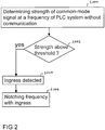
- Fig. 2 a flowchart of a further embodiment is depicted.
- the frequency with the ingress is notched during transmission of power line communication signals in the power line communication system (S106).
- the frequency is notched, e.g. by not using a frequency carrier which might influence the frequency of the ingress.
- a frequency carrier which might influence the frequency of the ingress.
- step S100 the strength of a common mode signal at a frequency of a power line communication system is determined when no communication in the power line communication system at this frequency takes place.
- step S300 the background noise is determined.
- the background noise might be determined by measuring the noise level in frequency bands adjacent to the frequency band used for radio broadcasting, like it is explained more in detail e.g. in ETSI TS 102 578.
- the strength is a predetermined value above the background noise (S302) then the corresponding frequency band is notched during transmission of power line communication signals (S304). Notching only frequency bands for which the strength of the common mode signal lies the predetermined value above the background noise further enhances the number of possible frequency bands. It is not necessary to notch frequency bands where the background noise is strong, since in this case it is not possible to receive the short wave radio broadcast signals in sufficient quality even without having a parallel power line communication system working.
- the predetermined value might be e.g. 14 dB.
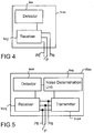
- the power line communication modem 400 comprises a receiver 402 which is configured to determine a strength of the common mode signal and a frequency of the power line communication system during a time period where no communication in the power line communication system at this frequency takes place and the detector 404 which is configured to detect the ingress if the strength of the common mode signal is above a predetermined threshold.
- the receiver 402 is connected to three lines of the power line network, a protective earth line PE, a phase line P and a neutral line N.
- a further embodiment of a power line communication modem 500 is depicted.
- the power line communication modem 500 further comprises a noise determination unit 406 which is configured to determine the background noise at the frequency.
- the power line communication modem 500 comprises a transmitter 408 which is also connected to the protective earth line PE, the phase line P and the neutral line N.
- the transmitter 408 is configured to notch a frequency or a plurality of frequencies or frequency bands during transmission of power line communication signals for which the strength of the common mode signal lies a predetermined value above the background noise.
- the receiver 402 has the ability to receive differential mode (DM) signals between phase P and neutral N, phase P and protection earth PE, neutral N and protective earth PE and common mode CM.
- Common mode signals carry the information of the ingress of radio broadcast signals louder than differential mode signals.
- the power line communication modem 400, 500 can access the common mode signals and detect the ingress with a less sensitive analog front end (AFE) or with a better certainty.
- AFE analog front end
- Multiple input-multiple output (MIMO) power line communication modems may have the ability to measure common mode signals. This ability can be reused to identify the existence of short wave radio broadcasts.
- MIMO Multiple input-multiple output
Landscapes
- Engineering & Computer Science (AREA)
- Computer Networks & Wireless Communication (AREA)
- Signal Processing (AREA)
- Power Engineering (AREA)
- Cable Transmission Systems, Equalization Of Radio And Reduction Of Echo (AREA)
Description
- An embodiment of the invention relates to a method for detecting an ingress of a short wave radio signal in a power line communication system. A further embodiment of the invention relates to a power line communication modem.
- Power line communication (PLC), also called mains communication, power line transmission or power line telecommunication (PLT), broadband power line (BPL), power band or power line networking (PLN) is a term describing several different systems for using power distribution wires for simultaneous distribution of data. A carrier can communicate voice and data by superimposing an analog signal of a standard 50 or 60 Hz alternating current (AC). For indoor applications, PLC equipment can use household electrical power wiring as a transmission medium. This is a technique used e.g. for home networking or in home automation for remote control of lighting and appliances without installation of additional wiring.
- In standard PLC systems the signals are transmitted and received in a differential mode (DM). Differential mode signaling is a method of transmitting information over pairs of wires. At DM signaling one wire carries a signal and the other wire carries the inverse of the signal, so that the sum of the voltages to ground on the two wires is always assumed to be zero. PLC modems therefore inject a DM signal between a neutral line and the phase line of an outlet of the power line network of the household for communication purposes. Another PLC modem can receive such DM signals at another outlet and use the DM signal for controlling an appliance associated with the receiving PLC modem.
- However, at in-house power line grids, there are asymmetric elements between the phase line and the neutral line, like e.g. an open light switch, the current bar and the fuse cabinet, branches, etc. At these asymmetric elements, the DM signals injected by PLC modems are converted to common mode (CM) signals. Multiple input-multiple output PLC modems can use different channels, in particular also common mode signals, in order to enhance the coverage of PLC systems.
- Fixed radio broadcasting or other external transmissions might have interferences with power line communication. PLC modems might have fixed notch filters for amateur radio bands. Concepts of dynamic or smart notching, e.g. like specified in ETSI TS 102 578, enables PLC modems to depict an ingress of fixed radio broadcast stations. The frequency where radio stations have been detected should be omitted by power line communication. In order to realize such an omission in a PLC transmitter, adaptive notch filters for suppressing a transmission signal in a predetermined frequency band might be used. There is a need of further improvements in detecting an ingress of short wave radio signals.
-
WO 2006/068327 discloses a method for detecting a balance status of a transmission line in a power line communication System by evaluating a status of a pair of conductors at the time of transmitting a signal by detecting a received signal. The received signal is caused by a pilot signal transmitted to the power line used for power line communication by a PLC modem device being part of the power line communication system. -
EP 1 499 033 describes a method for detecting frequency bands which are occupied by broadcast services. The method comprises screening the entire frequency range designated for power line communication during gaps in the time framing or the frequency band of the power line communication. - Tsuzuki et al., "Characteristics of Power-Line Channels in Cargo Ships", 2007 IEEE International Symposium on Power Line Communications and Its Applications, Pisa, Italy, 26-28 March 2007, describes the characteristics of power-line channels in cargo ships.
-
US 6,052,420 describes adaptive multiple sub-band common-mode RFI suppression in order to suppress common mode noise at the receiver side.. - It is an object of the invention to provide a method for detecting an ingress of a short wave radio signal and a power line communication modern with improved capabilities to detect the ingress.
- The claimed subject matter is defined in the appended independent claims. Further refinements are provided in the dependent claims.
- Further details of the invention will become apparent from a consideration of the drawings and ensuing description.
- The accompanying drawings are included to provide a further understanding of embodiments and are incorporated in and constitute a part of this specification. The drawings illustrate embodiments and together with the description serve to explain principles of embodiments. Other embodiments and many of the intended advantages of the embodiments will be readily appreciated, as they become better understood by reference to the following detailed description. The elements of the drawings are not necessarily to scale relative to each other. Like reference numerals designate corresponding similar parts.
- Fig. 1
- shows a schematic flowchart of an embodiment of the invention.
- Fig. 2
- shows a schematic flowchart of a further embodiment of the Invention,
- Fig. 3
- shows a schematic flowchart of a further embodiment of the invention,
- Fig. 4
- shows an embodiment of a power line communication modem and
- Fig. 5
- shows a further embodiment of a power line communication modem.
- In the following, embodiments of the invention are described. It is important to note that all described embodiments in the following may be combined in any way, i.e. there is no limitation that certain described embodiments may not be combined with others. Further, it should be noted that same reference signs throughout the Figures denote same or similar elements.
- It is to be understood that other embodiments may be utilized and structural or logical changes may be made without departing from the scope of the invention. The following detailed description, therefore, is not to be taken in a limiting sense, and the scope of the present invention is defined by the appended claims.
- It is to be understood that the features of the various embodiment described herein may be combined with each other, unless specifically noted otherwise.
- In
Fig. 1 a schematic flowchart of a method for detecting an ingress of the short wave radio signal in a power line communication is depicted. - In step S100 a strength of a common mode signal at a frequency of a power line communication system is determined during a time period when no communication in the power line communication system at this frequency takes place. Since no communication in the power line communication system takes place a common mode signal at this frequency indicates that an external source or some noise is present at this frequency. The term "frequency" might be understood in the context of this application also as "frequency band", which is used for communicating within the power line communication system.
- The strength of the common mode signal might be an amplitude of the signal or a power of the signal at the frequency.
- In step S102 it is determined whether the strength of the common mode signal is above a predetermined threshold. If the strength is above the predetermined threshold then an ingress is detected (S104), otherwise no ingress is determined.
- Common mode signals (CM) carry the ingress information of short wave radio broadcast signals with a higher volume than differential mode signals (DM). Thus, detection can be performed with a higher certainty using common mode signals than using different mode (DM) signal. CM signals might show a higher level than DM signals since DM mode signals are converted by the asymmetry of the power line network. There will be less false detections in identifying the ingress of available broadcast services. Unintended noise sources to the power line can be separated from radio broadcast ingress by comparing differential mode and common mode signals. Usually appliances feed noise in differential mode to power lines.
- Different predetermined thresholds might be used for different frequencies or frequency bands. Thus, when determining respective strengths of common mode signals at respective different frequencies during the time period when no communication in the power line communication system takes place at the respective frequencies, comparing the respective strength with respective thresholds and detecting the ingress with at least one of the respective strengths is above the respective threshold it is possible to identify different frequencies for which ingresses are present.
- In
Fig. 2 a flowchart of a further embodiment is depicted. After an ingress is detected in S104 the frequency with the ingress is notched during transmission of power line communication signals in the power line communication system (S106). The frequency is notched, e.g. by not using a frequency carrier which might influence the frequency of the ingress. Thus, there is no disturbing interference with external short wave radio signals when using the power line communication system. Therefore, a coexistence of power line communication systems with short wave radio signals or broadcast radio signals is possible. If ingresses at a plurality of different frequencies or frequency bands are detected, the corresponding plurality of different frequencies might be notched during communication over the power line communication network. - In
Fig. 3 a further flowchart is depicted. In step S100 the strength of a common mode signal at a frequency of a power line communication system is determined when no communication in the power line communication system at this frequency takes place. - In step S300 the background noise is determined. The background noise might be determined by measuring the noise level in frequency bands adjacent to the frequency band used for radio broadcasting, like it is explained more in detail e.g. in ETSI TS 102 578.
- If the strength is a predetermined value above the background noise (S302) then the corresponding frequency band is notched during transmission of power line communication signals (S304). Notching only frequency bands for which the strength of the common mode signal lies the predetermined value above the background noise further enhances the number of possible frequency bands. It is not necessary to notch frequency bands where the background noise is strong, since in this case it is not possible to receive the short wave radio broadcast signals in sufficient quality even without having a parallel power line communication system working. The predetermined value might be e.g. 14 dB.
- In
Fig. 4 a powerline communication modem 400 is depicted. The powerline communication modem 400 comprises areceiver 402 which is configured to determine a strength of the common mode signal and a frequency of the power line communication system during a time period where no communication in the power line communication system at this frequency takes place and thedetector 404 which is configured to detect the ingress if the strength of the common mode signal is above a predetermined threshold. - The
receiver 402 is connected to three lines of the power line network, a protective earth line PE, a phase line P and a neutral line N. - In
Fig. 5 a further embodiment of a power line communication modem 500 is depicted. Besides thereceiver 402 and thedetector 404 the power line communication modem 500 further comprises anoise determination unit 406 which is configured to determine the background noise at the frequency. Further, the power line communication modem 500 comprises atransmitter 408 which is also connected to the protective earth line PE, the phase line P and the neutral line N. Thetransmitter 408 is configured to notch a frequency or a plurality of frequencies or frequency bands during transmission of power line communication signals for which the strength of the common mode signal lies a predetermined value above the background noise. - The
receiver 402 has the ability to receive differential mode (DM) signals between phase P and neutral N, phase P and protection earth PE, neutral N and protective earth PE and common mode CM. Common mode signals carry the information of the ingress of radio broadcast signals louder than differential mode signals. Thus the powerline communication modem 400, 500 can access the common mode signals and detect the ingress with a less sensitive analog front end (AFE) or with a better certainty. - Multiple input-multiple output (MIMO) power line communication modems may have the ability to measure common mode signals. This ability can be reused to identify the existence of short wave radio broadcasts.
- When comparing the strength of at least one differential mode signal between phase line and neutral line, phase line and protective earth line, and neutral line and protective earth line at the frequency of the power line communication system during the time period when no communication in the power line communication system at this frequency takes place, and the strengths of common mode signals an unintended noise injected by any device connected to the mains can be identified as well. This reduces the risk of false detection at dynamic adaptive notching. Usually any unintended noise injected to the mains has a stronger differential mode signal than the common mode signal.
- With the method and power line communication modem better dynamic (or smart or adaptive) notching is achieved.
- Although specific embodiments have been illustrated and described herein, it will be appreciated by those of ordinary skill in the art that a variety of ultra net and/or equivalent implementations may be substituted for the specific embodiments shown and described without departing from the scope of the described embodiments. This application is intended to cover any adaptations or variations of the specific embodiments discussed herein. Therefore, it is intended that this invention be limited only by the claims and the equivalents thereof.
Claims (9)
- Method for detecting an ingress of a short-wave radio signal in a power line communication system characterized by:determining a strength of a common-mode signal indicative of an external source or noise at a frequency of the power line communication system during a time period when no communication in the power line communication system at this frequency takes place; anddetecting the ingress of the short-wave radio signal if the strength of the common-mode signal is above a predetermined threshold;determining a strength of at least one differential mode signal between phase line and neutral line, phase line and protective earth line, and neutral line and protective earth line at the frequency of the power line communication system during the time period when no communication in the power line communication system at this frequency takes place, wherein the detecting of the ingress is based on the strength of the at least one differential mode signal;wherein the detecting of the ingress is further based on a comparison of the differential mode and the common mode signals.
- Method according to claim 1 further comprising:determining respective strengths of common-mode signals at respective different frequencies during the time period during time periods when no communication in the power line communication system at the respective frequencies takes place;comparing the respective strengths with respective thresholds; anddetecting the ingress of the short-wave radio signal if at least one of the respective strengths is above the respective threshold.
- Method according to any of claims 1 to 2, further comprising:
notching a frequency during transmission of power line communication signals, for which an ingress has been detected. - Method according to claims 1 to 2, further comprising:determining a background noise; andnotching a frequency during transmission of power line communication signals, for which the strength of the common-mode signal is a predetermined value above the background noise.
- Power line communication modem (400, 500) for detecting an ingress of a short-wave radio signal in a power line communication system characterized by:a receiver (402) configured to determine a strength of a common-mode signal indicative of an external source or noise at a frequency of the power line communication system during a time period when no communication in the power line communication system at this frequency takes place; anda detector (404) configured to detect the ingress of the short-wave radio signal if the strength of the common-mode signal is above a predetermined threshold;wherein the receiver (402) is further configured to determine a strength of at least one differential mode signals between phase line and neutral line, phase line and protective earth line, and neutral line and protective earth line at the frequency of the power line communication system during the time period when no communication in the power line communication system at this frequency takes place, and the detector (404) is further configured to detect the ingress based on the strength of the at least one differential mode signal;wherein the detecting of the ingress is further based on a comparison of the differential mode and the common mode signals.
- Power line communication modem according to claim 5, wherein the receiver (402) is further configured to determine respective strengths of common-mode signals at respective different frequencies during the time period during time periods when no communication in the power line communication system at the respective frequencies takes place; and wherein the detector (404) is further configured to compare the respective strengths with respective thresholds and to detect the ingress of the short-wave radio signal if at least one of the respective strengths is above the respective threshold.
- Power line communication modem according to claims 5 or 6, further comprising:
a transmitter (408) configured to notch a frequency during transmission of power line communication signals, for which an ingress has been detected. - Power line communication modem according to claims 5 or 6, further comprising:a noise determination unit (406) configured to determine a background noise; anda transmitter (408) configured to notch a frequency during transmission of power line communication signals, for which the strength of the common-mode signal is a predetermined value above the background noise.
- Power line communication modem according to claims 7 to 8, wherein the power line communication modem is configured to receive and to transmit power line communication signals in a multiple input multiple output scheme.
Priority Applications (7)
| Application Number | Priority Date | Filing Date | Title |
|---|---|---|---|
| EP08014312.6A EP2154789B1 (en) | 2008-08-11 | 2008-08-11 | Method for detecting an ingress of a short-wave radio signal in a power line communication system and power line communication modem |
| CN200980131287.9A CN102119491B (en) | 2008-08-11 | 2009-05-08 | Method for detecting an ingress of a short-wave radio signal in a power line communication system and power line communication modem |
| BRPI0917116A BRPI0917116A2 (en) | 2008-08-11 | 2009-05-08 | method for detecting a shortwave radio signal entering a power line communication system, and, power line communication modem. |
| PCT/EP2009/003303 WO2010017854A1 (en) | 2008-08-11 | 2009-05-08 | Method for detecting an ingress of a short-wave radio signal in a power line communication system and power line communication modem |
| US13/058,018 US8934860B2 (en) | 2008-08-11 | 2009-05-08 | Method for detecting an ingress of a short-wave radio signal in a power line communication system and power line communication modem |
| RU2011109037/07A RU2499355C2 (en) | 2008-08-11 | 2009-05-08 | Method of detecting intrusion of short-wave radio signal into power line data transmission system and power line data transmission modem |
| KR1020117003159A KR101556431B1 (en) | 2008-08-11 | 2009-05-08 | Method for detecting an ingress of a short-wave radio signal in a power line communication system and power line communication modem |
Applications Claiming Priority (1)
| Application Number | Priority Date | Filing Date | Title |
|---|---|---|---|
| EP08014312.6A EP2154789B1 (en) | 2008-08-11 | 2008-08-11 | Method for detecting an ingress of a short-wave radio signal in a power line communication system and power line communication modem |
Publications (2)
| Publication Number | Publication Date |
|---|---|
| EP2154789A1 EP2154789A1 (en) | 2010-02-17 |
| EP2154789B1 true EP2154789B1 (en) | 2019-10-02 |
Family
ID=40256841
Family Applications (1)
| Application Number | Title | Priority Date | Filing Date |
|---|---|---|---|
| EP08014312.6A Active EP2154789B1 (en) | 2008-08-11 | 2008-08-11 | Method for detecting an ingress of a short-wave radio signal in a power line communication system and power line communication modem |
Country Status (7)
| Country | Link |
|---|---|
| US (1) | US8934860B2 (en) |
| EP (1) | EP2154789B1 (en) |
| KR (1) | KR101556431B1 (en) |
| CN (1) | CN102119491B (en) |
| BR (1) | BRPI0917116A2 (en) |
| RU (1) | RU2499355C2 (en) |
| WO (1) | WO2010017854A1 (en) |
Families Citing this family (13)
| Publication number | Priority date | Publication date | Assignee | Title |
|---|---|---|---|---|
| KR20100017537A (en) | 2007-05-02 | 2010-02-16 | 코퍼게이트 커뮤니케이션 리미티드 | Multiple input, multiple output(mimo) communication system over in-premises wires |
| EP2494702B1 (en) | 2009-10-26 | 2017-09-20 | Sony Corporation | Device for use in a power line communication system, power line communication systems and power line communication method |
| DE102010051710B4 (en) * | 2010-07-21 | 2013-03-14 | Power Plus Communications Ag | Method for assessing the usability of a subcarrier of a broadband powerline signal |
| US8520696B1 (en) | 2010-07-30 | 2013-08-27 | Qualcomm Incorporated | Terminal selection diversity for powerline communications |
| US9350423B2 (en) * | 2011-06-30 | 2016-05-24 | The Boeing Company | Methods and system for increasing data transmission rates across a three-phase power system |
| EP2744117B1 (en) * | 2012-12-13 | 2016-08-17 | Deutsche Telekom AG | Method for reducing interference in a communication network |
| US9130658B2 (en) | 2013-05-06 | 2015-09-08 | Qualcomm Incorporated | Selection diversity in a powerline communication system |
| US20150111583A1 (en) * | 2013-10-21 | 2015-04-23 | Qualcomm Incorporated | Communicating detection of controlled radio frequencies |
| CN104202068A (en) * | 2014-09-04 | 2014-12-10 | 国家电网公司 | Medium-short-wave radio broadcast signal detection method |
| CN104683004A (en) * | 2014-12-10 | 2015-06-03 | 中国人民解放军63888部队 | Short-wave communication adaptive frequency automatic acquisition and input method and system thereof |
| US10142131B2 (en) | 2017-02-14 | 2018-11-27 | Hysky Technologies, Inc. | Intelligent shortwave frequency management systems and associated methods |
| US11323435B2 (en) | 2019-05-08 | 2022-05-03 | The Boeing Company | Method and apparatus for advanced security systems over a power line connection |
| CN112165342B (en) * | 2020-11-09 | 2021-09-21 | 华北电力大学 | Noise detection method and system by using mode feature vector |
Citations (1)
| Publication number | Priority date | Publication date | Assignee | Title |
|---|---|---|---|---|
| US6052420A (en) * | 1997-05-15 | 2000-04-18 | Northern Telecom Limited | Adaptive multiple sub-band common-mode RFI suppression |
Family Cites Families (11)
| Publication number | Priority date | Publication date | Assignee | Title |
|---|---|---|---|---|
| DE2364043C2 (en) * | 1973-01-19 | 1984-01-05 | Sharp K.K., Osaka | Home transmission system |
| EP1096695B1 (en) * | 1999-10-28 | 2012-03-21 | STMicroelectronics S.r.l. | Multichannel transceiver of digital signals over power lines |
| RU2239270C1 (en) * | 2003-03-31 | 2004-10-27 | Общество с ограниченной ответственностью "Алгоритм" | Device for suppressing radiation induced by transmitting data in power lines |
| EP1499033B1 (en) | 2003-07-16 | 2007-03-28 | Sony Deutschland GmbH | Detection of broadcast signals for defining useable frequency bands for powerline communication |
| JP4561962B2 (en) * | 2004-01-30 | 2010-10-13 | Tdk株式会社 | Signal detection device |
| JP5052742B2 (en) * | 2004-07-22 | 2012-10-17 | パナソニック株式会社 | Transmitting apparatus and communication system using the same |
| EP1832007A1 (en) | 2004-12-24 | 2007-09-12 | Matsushita Electric Industrial Co., Ltd. | Line status detection apparatus, communication apparatus, and line status detection method |
| JP2006245802A (en) * | 2005-03-01 | 2006-09-14 | Mitsubishi Electric Corp | Power line carrier communication system and communication apparatus thereof, and buildup method of power line carrier communication system |
| US7873322B2 (en) | 2005-06-14 | 2011-01-18 | Acterna Llc | Ingress susceptibility on return path |
| EP2800285B1 (en) * | 2006-08-24 | 2019-10-02 | Sony Deutschland Gmbh | Method for transmitting a signal on a power line network, transmitting unit, receiving unit and system |
| EP3065303B1 (en) * | 2007-08-22 | 2019-01-02 | Sony Corporation | Method for transmitting a signal via a power line network, transmitter, receiver, power line communication modem and power line communication system |
-
2008
- 2008-08-11 EP EP08014312.6A patent/EP2154789B1/en active Active
-
2009
- 2009-05-08 RU RU2011109037/07A patent/RU2499355C2/en active
- 2009-05-08 US US13/058,018 patent/US8934860B2/en active Active
- 2009-05-08 KR KR1020117003159A patent/KR101556431B1/en active IP Right Grant
- 2009-05-08 BR BRPI0917116A patent/BRPI0917116A2/en not_active IP Right Cessation
- 2009-05-08 CN CN200980131287.9A patent/CN102119491B/en not_active Expired - Fee Related
- 2009-05-08 WO PCT/EP2009/003303 patent/WO2010017854A1/en active Application Filing
Patent Citations (1)
| Publication number | Priority date | Publication date | Assignee | Title |
|---|---|---|---|---|
| US6052420A (en) * | 1997-05-15 | 2000-04-18 | Northern Telecom Limited | Adaptive multiple sub-band common-mode RFI suppression |
Non-Patent Citations (2)
| Title |
|---|
| "PowerLine Telecommunications (PLT); Coexistence between PLT Modems and fixed SW Radio broadcasting services", ETSI DRAFT; PLT41_TD_26_TS_102578V010102.DOC, EUROPEAN TELECOMMUNICATIONS STANDARDS INSTITUTE (ETSI), 650, ROUTE DES LUCIOLES ; F-06921 SOPHIA-ANTIPOLIS ; FRANCE, no. V1.1.2, 18 May 2007 (2007-05-18), pages 1 - 14, XP014051075 * |
| TSUZUKI S ET AL: "Characteristics of Power-Line Channels in Cargo Ships", 2007 IEEE INTERNATIONAL SYMPOSIUM ON POWER LINE COMMUNICATIONS AND ITS APPLICATIONS : [2007 IEEE ISPLC] ; PISA, ITALY, 26 - 28 MARCH 2007, IEEE SERVICE CENTER, PISCATAWAY, NJ, 1 March 2007 (2007-03-01), pages 324 - 329, XP031176355, ISBN: 978-1-4244-1089-7, DOI: 10.1109/ISPLC.2007.371145 * |
Also Published As
| Publication number | Publication date |
|---|---|
| US20110142110A1 (en) | 2011-06-16 |
| CN102119491A (en) | 2011-07-06 |
| RU2499355C2 (en) | 2013-11-20 |
| BRPI0917116A2 (en) | 2015-11-10 |
| EP2154789A1 (en) | 2010-02-17 |
| KR101556431B1 (en) | 2015-10-01 |
| CN102119491B (en) | 2014-09-03 |
| US8934860B2 (en) | 2015-01-13 |
| WO2010017854A1 (en) | 2010-02-18 |
| RU2011109037A (en) | 2012-09-20 |
| KR20110044755A (en) | 2011-04-29 |
Similar Documents
| Publication | Publication Date | Title |
|---|---|---|
| EP2154789B1 (en) | Method for detecting an ingress of a short-wave radio signal in a power line communication system and power line communication modem | |
| EP1892843B1 (en) | Method for transmitting a signal on a power line network, transmitting unit, receiving unit and system | |
| EP2580871B1 (en) | Method for operating a plc system, plc modem device and plc system | |
| CN101772901B (en) | Method for transmitting a signal over a power line channel and power line communication modem | |
| US8879644B2 (en) | Power line communications method and apparatus | |
| US20160127056A1 (en) | Power line communication operating frequency band selection apparatus, systems and methods | |
| Schwager | Powerline communications: Significant technologies to become ready for integration | |
| US9143198B2 (en) | Power line communication method and apparatus | |
| JP2010534990A5 (en) | ||
| US9479221B2 (en) | Power line communication method and apparatus | |
| JP2008092238A (en) | Power-line communication device and power-line communication system | |
| WO2012146326A1 (en) | Method for operating a power line communication system, power line communication device, power line communication system | |
| Schwager et al. | Cognitive frequency exclusion in EN 50561-1: 2012 |
Legal Events
| Date | Code | Title | Description |
|---|---|---|---|
| PUAI | Public reference made under article 153(3) epc to a published international application that has entered the european phase |
Free format text: ORIGINAL CODE: 0009012 |
|
| AK | Designated contracting states |
Kind code of ref document: A1 Designated state(s): AT BE BG CH CY CZ DE DK EE ES FI FR GB GR HR HU IE IS IT LI LT LU LV MC MT NL NO PL PT RO SE SI SK TR |
|
| AX | Request for extension of the european patent |
Extension state: AL BA MK RS |
|
| 17P | Request for examination filed |
Effective date: 20100726 |
|
| 17Q | First examination report despatched |
Effective date: 20100901 |
|
| AKX | Designation fees paid |
Designated state(s): AT BE BG CH CY CZ DE DK EE ES FI FR GB GR HR HU IE IS IT LI LT LU LV MC MT NL NO PL PT RO SE SI SK TR |
|
| STAA | Information on the status of an ep patent application or granted ep patent |
Free format text: STATUS: EXAMINATION IS IN PROGRESS |
|
| GRAP | Despatch of communication of intention to grant a patent |
Free format text: ORIGINAL CODE: EPIDOSNIGR1 |
|
| STAA | Information on the status of an ep patent application or granted ep patent |
Free format text: STATUS: GRANT OF PATENT IS INTENDED |
|
| INTG | Intention to grant announced |
Effective date: 20190409 |
|
| GRAS | Grant fee paid |
Free format text: ORIGINAL CODE: EPIDOSNIGR3 |
|
| GRAA | (expected) grant |
Free format text: ORIGINAL CODE: 0009210 |
|
| STAA | Information on the status of an ep patent application or granted ep patent |
Free format text: STATUS: THE PATENT HAS BEEN GRANTED |
|
| AK | Designated contracting states |
Kind code of ref document: B1 Designated state(s): AT BE BG CH CY CZ DE DK EE ES FI FR GB GR HR HU IE IS IT LI LT LU LV MC MT NL NO PL PT RO SE SI SK TR |
|
| REG | Reference to a national code |
Ref country code: GB Ref legal event code: FG4D |
|
| REG | Reference to a national code |
Ref country code: CH Ref legal event code: EP Ref country code: AT Ref legal event code: REF Ref document number: 1187349 Country of ref document: AT Kind code of ref document: T Effective date: 20191015 |
|
| REG | Reference to a national code |
Ref country code: DE Ref legal event code: R096 Ref document number: 602008061315 Country of ref document: DE |
|
| REG | Reference to a national code |
Ref country code: IE Ref legal event code: FG4D |
|
| REG | Reference to a national code |
Ref country code: NL Ref legal event code: MP Effective date: 20191002 |
|
| REG | Reference to a national code |
Ref country code: LT Ref legal event code: MG4D |
|
| REG | Reference to a national code |
Ref country code: AT Ref legal event code: MK05 Ref document number: 1187349 Country of ref document: AT Kind code of ref document: T Effective date: 20191002 |
|
| PG25 | Lapsed in a contracting state [announced via postgrant information from national office to epo] |
Ref country code: ES Free format text: LAPSE BECAUSE OF FAILURE TO SUBMIT A TRANSLATION OF THE DESCRIPTION OR TO PAY THE FEE WITHIN THE PRESCRIBED TIME-LIMIT Effective date: 20191002 Ref country code: LV Free format text: LAPSE BECAUSE OF FAILURE TO SUBMIT A TRANSLATION OF THE DESCRIPTION OR TO PAY THE FEE WITHIN THE PRESCRIBED TIME-LIMIT Effective date: 20191002 Ref country code: SE Free format text: LAPSE BECAUSE OF FAILURE TO SUBMIT A TRANSLATION OF THE DESCRIPTION OR TO PAY THE FEE WITHIN THE PRESCRIBED TIME-LIMIT Effective date: 20191002 Ref country code: PL Free format text: LAPSE BECAUSE OF FAILURE TO SUBMIT A TRANSLATION OF THE DESCRIPTION OR TO PAY THE FEE WITHIN THE PRESCRIBED TIME-LIMIT Effective date: 20191002 Ref country code: GR Free format text: LAPSE BECAUSE OF FAILURE TO SUBMIT A TRANSLATION OF THE DESCRIPTION OR TO PAY THE FEE WITHIN THE PRESCRIBED TIME-LIMIT Effective date: 20200103 Ref country code: NO Free format text: LAPSE BECAUSE OF FAILURE TO SUBMIT A TRANSLATION OF THE DESCRIPTION OR TO PAY THE FEE WITHIN THE PRESCRIBED TIME-LIMIT Effective date: 20200102 Ref country code: LT Free format text: LAPSE BECAUSE OF FAILURE TO SUBMIT A TRANSLATION OF THE DESCRIPTION OR TO PAY THE FEE WITHIN THE PRESCRIBED TIME-LIMIT Effective date: 20191002 Ref country code: PT Free format text: LAPSE BECAUSE OF FAILURE TO SUBMIT A TRANSLATION OF THE DESCRIPTION OR TO PAY THE FEE WITHIN THE PRESCRIBED TIME-LIMIT Effective date: 20200203 Ref country code: FI Free format text: LAPSE BECAUSE OF FAILURE TO SUBMIT A TRANSLATION OF THE DESCRIPTION OR TO PAY THE FEE WITHIN THE PRESCRIBED TIME-LIMIT Effective date: 20191002 Ref country code: BG Free format text: LAPSE BECAUSE OF FAILURE TO SUBMIT A TRANSLATION OF THE DESCRIPTION OR TO PAY THE FEE WITHIN THE PRESCRIBED TIME-LIMIT Effective date: 20200102 Ref country code: NL Free format text: LAPSE BECAUSE OF FAILURE TO SUBMIT A TRANSLATION OF THE DESCRIPTION OR TO PAY THE FEE WITHIN THE PRESCRIBED TIME-LIMIT Effective date: 20191002 Ref country code: AT Free format text: LAPSE BECAUSE OF FAILURE TO SUBMIT A TRANSLATION OF THE DESCRIPTION OR TO PAY THE FEE WITHIN THE PRESCRIBED TIME-LIMIT Effective date: 20191002 |
|
| PG25 | Lapsed in a contracting state [announced via postgrant information from national office to epo] |
Ref country code: CZ Free format text: LAPSE BECAUSE OF FAILURE TO SUBMIT A TRANSLATION OF THE DESCRIPTION OR TO PAY THE FEE WITHIN THE PRESCRIBED TIME-LIMIT Effective date: 20191002 Ref country code: IS Free format text: LAPSE BECAUSE OF FAILURE TO SUBMIT A TRANSLATION OF THE DESCRIPTION OR TO PAY THE FEE WITHIN THE PRESCRIBED TIME-LIMIT Effective date: 20200224 Ref country code: HR Free format text: LAPSE BECAUSE OF FAILURE TO SUBMIT A TRANSLATION OF THE DESCRIPTION OR TO PAY THE FEE WITHIN THE PRESCRIBED TIME-LIMIT Effective date: 20191002 |
|
| REG | Reference to a national code |
Ref country code: DE Ref legal event code: R097 Ref document number: 602008061315 Country of ref document: DE |
|
| PG2D | Information on lapse in contracting state deleted |
Ref country code: IS |
|
| PG25 | Lapsed in a contracting state [announced via postgrant information from national office to epo] |
Ref country code: RO Free format text: LAPSE BECAUSE OF FAILURE TO SUBMIT A TRANSLATION OF THE DESCRIPTION OR TO PAY THE FEE WITHIN THE PRESCRIBED TIME-LIMIT Effective date: 20191002 Ref country code: DK Free format text: LAPSE BECAUSE OF FAILURE TO SUBMIT A TRANSLATION OF THE DESCRIPTION OR TO PAY THE FEE WITHIN THE PRESCRIBED TIME-LIMIT Effective date: 20191002 Ref country code: EE Free format text: LAPSE BECAUSE OF FAILURE TO SUBMIT A TRANSLATION OF THE DESCRIPTION OR TO PAY THE FEE WITHIN THE PRESCRIBED TIME-LIMIT Effective date: 20191002 Ref country code: IS Free format text: LAPSE BECAUSE OF FAILURE TO SUBMIT A TRANSLATION OF THE DESCRIPTION OR TO PAY THE FEE WITHIN THE PRESCRIBED TIME-LIMIT Effective date: 20200202 |
|
| PLBE | No opposition filed within time limit |
Free format text: ORIGINAL CODE: 0009261 |
|
| STAA | Information on the status of an ep patent application or granted ep patent |
Free format text: STATUS: NO OPPOSITION FILED WITHIN TIME LIMIT |
|
| PG25 | Lapsed in a contracting state [announced via postgrant information from national office to epo] |
Ref country code: SK Free format text: LAPSE BECAUSE OF FAILURE TO SUBMIT A TRANSLATION OF THE DESCRIPTION OR TO PAY THE FEE WITHIN THE PRESCRIBED TIME-LIMIT Effective date: 20191002 Ref country code: IT Free format text: LAPSE BECAUSE OF FAILURE TO SUBMIT A TRANSLATION OF THE DESCRIPTION OR TO PAY THE FEE WITHIN THE PRESCRIBED TIME-LIMIT Effective date: 20191002 |
|
| 26N | No opposition filed |
Effective date: 20200703 |
|
| PG25 | Lapsed in a contracting state [announced via postgrant information from national office to epo] |
Ref country code: SI Free format text: LAPSE BECAUSE OF FAILURE TO SUBMIT A TRANSLATION OF THE DESCRIPTION OR TO PAY THE FEE WITHIN THE PRESCRIBED TIME-LIMIT Effective date: 20191002 |
|
| PG25 | Lapsed in a contracting state [announced via postgrant information from national office to epo] |
Ref country code: MC Free format text: LAPSE BECAUSE OF FAILURE TO SUBMIT A TRANSLATION OF THE DESCRIPTION OR TO PAY THE FEE WITHIN THE PRESCRIBED TIME-LIMIT Effective date: 20191002 |
|
| REG | Reference to a national code |
Ref country code: CH Ref legal event code: PL |
|
| GBPC | Gb: european patent ceased through non-payment of renewal fee |
Effective date: 20200811 |
|
| PG25 | Lapsed in a contracting state [announced via postgrant information from national office to epo] |
Ref country code: LI Free format text: LAPSE BECAUSE OF NON-PAYMENT OF DUE FEES Effective date: 20200831 Ref country code: CH Free format text: LAPSE BECAUSE OF NON-PAYMENT OF DUE FEES Effective date: 20200831 Ref country code: LU Free format text: LAPSE BECAUSE OF NON-PAYMENT OF DUE FEES Effective date: 20200811 |
|
| REG | Reference to a national code |
Ref country code: BE Ref legal event code: MM Effective date: 20200831 |
|
| PG25 | Lapsed in a contracting state [announced via postgrant information from national office to epo] |
Ref country code: FR Free format text: LAPSE BECAUSE OF NON-PAYMENT OF DUE FEES Effective date: 20200831 |
|
| PG25 | Lapsed in a contracting state [announced via postgrant information from national office to epo] |
Ref country code: BE Free format text: LAPSE BECAUSE OF NON-PAYMENT OF DUE FEES Effective date: 20200831 Ref country code: IE Free format text: LAPSE BECAUSE OF NON-PAYMENT OF DUE FEES Effective date: 20200811 Ref country code: GB Free format text: LAPSE BECAUSE OF NON-PAYMENT OF DUE FEES Effective date: 20200811 |
|
| PG25 | Lapsed in a contracting state [announced via postgrant information from national office to epo] |
Ref country code: TR Free format text: LAPSE BECAUSE OF FAILURE TO SUBMIT A TRANSLATION OF THE DESCRIPTION OR TO PAY THE FEE WITHIN THE PRESCRIBED TIME-LIMIT Effective date: 20191002 Ref country code: MT Free format text: LAPSE BECAUSE OF FAILURE TO SUBMIT A TRANSLATION OF THE DESCRIPTION OR TO PAY THE FEE WITHIN THE PRESCRIBED TIME-LIMIT Effective date: 20191002 Ref country code: CY Free format text: LAPSE BECAUSE OF FAILURE TO SUBMIT A TRANSLATION OF THE DESCRIPTION OR TO PAY THE FEE WITHIN THE PRESCRIBED TIME-LIMIT Effective date: 20191002 |
|
| PGFP | Annual fee paid to national office [announced via postgrant information from national office to epo] |
Ref country code: DE Payment date: 20220616 Year of fee payment: 15 |
|
| P01 | Opt-out of the competence of the unified patent court (upc) registered |
Effective date: 20230527 |
|
| REG | Reference to a national code |
Ref country code: DE Ref legal event code: R119 Ref document number: 602008061315 Country of ref document: DE |