EP2149667A2 - Window covering having at least one deformable connector - Google Patents
Window covering having at least one deformable connector Download PDFInfo
- Publication number
- EP2149667A2 EP2149667A2 EP08165163A EP08165163A EP2149667A2 EP 2149667 A2 EP2149667 A2 EP 2149667A2 EP 08165163 A EP08165163 A EP 08165163A EP 08165163 A EP08165163 A EP 08165163A EP 2149667 A2 EP2149667 A2 EP 2149667A2
- Authority
- EP
- European Patent Office
- Prior art keywords
- connector
- window covering
- pulley
- cord
- rail
- Prior art date
- Legal status (The legal status is an assumption and is not a legal conclusion. Google has not performed a legal analysis and makes no representation as to the accuracy of the status listed.)
- Granted
Links
Images


Classifications
-
- E—FIXED CONSTRUCTIONS
- E06—DOORS, WINDOWS, SHUTTERS, OR ROLLER BLINDS IN GENERAL; LADDERS
- E06B—FIXED OR MOVABLE CLOSURES FOR OPENINGS IN BUILDINGS, VEHICLES, FENCES OR LIKE ENCLOSURES IN GENERAL, e.g. DOORS, WINDOWS, BLINDS, GATES
- E06B9/00—Screening or protective devices for wall or similar openings, with or without operating or securing mechanisms; Closures of similar construction
- E06B9/24—Screens or other constructions affording protection against light, especially against sunshine; Similar screens for privacy or appearance; Slat blinds
- E06B9/26—Lamellar or like blinds, e.g. venetian blinds
- E06B9/28—Lamellar or like blinds, e.g. venetian blinds with horizontal lamellae, e.g. non-liftable
- E06B9/30—Lamellar or like blinds, e.g. venetian blinds with horizontal lamellae, e.g. non-liftable liftable
- E06B9/32—Operating, guiding, or securing devices therefor
- E06B9/322—Details of operating devices, e.g. pulleys, brakes, spring drums, drives
-
- E—FIXED CONSTRUCTIONS
- E06—DOORS, WINDOWS, SHUTTERS, OR ROLLER BLINDS IN GENERAL; LADDERS
- E06B—FIXED OR MOVABLE CLOSURES FOR OPENINGS IN BUILDINGS, VEHICLES, FENCES OR LIKE ENCLOSURES IN GENERAL, e.g. DOORS, WINDOWS, BLINDS, GATES
- E06B9/00—Screening or protective devices for wall or similar openings, with or without operating or securing mechanisms; Closures of similar construction
- E06B9/24—Screens or other constructions affording protection against light, especially against sunshine; Similar screens for privacy or appearance; Slat blinds
- E06B9/26—Lamellar or like blinds, e.g. venetian blinds
- E06B9/262—Lamellar or like blinds, e.g. venetian blinds with flexibly-interconnected horizontal or vertical strips; Concertina blinds, i.e. upwardly folding flexible screens
Definitions
- the invention relates to window coverings.
- Window coverings such as venetian blinds, roman shades, cellular shades or pleated shades, often have a headrail, a bottom rail and window covering material between the headrail and the bottom rail.
- U.S. Patent Nos. 13,251 , 2,687,769 , 5,193,601 , 5,482,750 , 6,234,236 , 6,325,131 , 6,644,3 72 , and 7,159,634 and U.S. Patent Application Publication Nos. 2007/0163727 , 2004/0129390 disclose examples of such window coverings.
- Window coverings are typically mounted adjacent a window and are used to cover the window and provide a desired aesthetic effect to the interior and exterior of a home, office or other building.
- the window covering material is often moveable from a retracted position adjacent the headrail to various extended positions that lower the bottom rail and permit the window covering material to cover a window.
- U.S. Patent No. 6,991,020 to Cheng et al discloses a window covering that utilizes a cord lock and an operator cord that extends through the cord lock and is attached to lift cords.
- the operator cord extends out of the cord lock and may be manipulated by a user to adjust the position of the window covering.
- U.S. Patent No. 6,837,294 to Cheng et al provides a similar disclosure to U.S. Patent No. 6,991,020 and also discloses a cordless shade that utilizes a spring motor that includes two spring motor cord spools attached to respective spring motor cord spools.
- a spring motor cord is entrained about the spring motor cord spools and is attached to lift cords.
- a user adjusts the position of the window covering material by providing a downward force to the bottom rail of the window covering to extend the window covering material or an upward force to the bottom rail to permit the spring motor to retract the lift cords and the window covering material.
- the need for the attachment of the cords in the lift systems disclosed by Cheng et al. to not pass over a pulley limits the extent to which the window covering material may be extended below the headrail to, at most, the length of the headrail. If the full length of the headrail is filled with cords, spools and spring motor to provide a maximum length of the window covering, the window covering cannot be used in stock window covering programs or cut down programs. In these programs, window coverings are made in a limited number of stock sizes, which may then be cut down by a retailer to fit a specific window opening dimension provided by a customer.
- Cut down programs typically offer blinds or shades for lower prices relative to custom made window coverings because a retailer is able to take advantage of economies of scale involved in the production of the limited number of available stock sized window coverings.
- Window coverings that can only provide a length of extended window covering material that is relatively equivalent to the length of a headrail typically cannot provide the window covering material length necessary for use in one or more stock blinds of window covering cut down programs.
- U.S. Patent Application No. 2004/0129390 discloses a window covering that includes lift cords connected to a spring motor by various interlocking gears or other transmission systems, Such interlocking gears or transmission systems can be expensive to manufacture. Moreover, such lift systems often require precise fabrication due to the need for the various interlocking components to reliably interact with each other. Often, only very large window coverings, which are typically much heavier and costlier than other window coverings, may economically include such systems and still be produced efficiently enough to meet the price expectations of a customer.
- a window covering is needed that includes a connection between one or more lift cords and one or more operator cords or spring motor cords that reduces, if not completely eliminates, cord entanglement problems or "hang up” problems so that the connection of the cords may reliably pass over, or pass along, one or more pulleys in a window covering lift system.
- a connection does not require interlocking gears or other expensive or complicated mechanisms to provide a cost effective solution to such cord entanglement or "hang up” problems.
- a window covering that includes a first rail, window covering material adjacent the first rail, one or more lift cords, multiple pulleys positioned adjacent the first rail, at least one spring motor adjacent the first rail, one or more spring motor cords extending from the one or more spring motors and a deformable connector attached to the one or more spring motor cords and the one or more lift cords.
- the window covering material is moveable from a retracted position to an extended position.
- the one or more spring motor cords are configured to extend away from the one or more spring motors and travel along a path defined by at least one of the pulleys when the window covering material is raised or lowered.
- the deformable connector is sized and configured to permit the one or more spring motor cords, connector and a portion of the one or more lift cords to pass over at least one of the pulleys during movement along the path.
- the connector is configured to assume a curved shape as the connector passes over at least one of the plurality of pulleys.
- my window covering may replace the spring motor and spring motor cord with a cord lock and one or more operator cords.
- the one or more operator cords include a first portion that passes through the cord lock and is attached to the connector. A user may raise or lower the blind by manipulating the operator cord. The first portion of the one or more operator cords move along the same path as the one or more spring motor cords would travel when the window covering is raised or lowered.
- the deformable connector may be a ring having a generally oval shaped body or a generally circular body. Of course, the deformable connector may also have other shapes. Preferably, the deformable connector is composed of rubber or plastic.
- the connector may be configured to deform to a first length when the connector is not passing along the surface of any of the pulleys and is configured to deform to a second length that is greater than the first length when the connector passes along the surface of any of the pulleys.
- the plurality of pulleys may include three pulleys that are aligned with each other adjacent one end of the first rail and three other pulleys that are aligned with each other adjacent the opposite end of the first rail.
- a pulley mount is positioned adjacent each end of the first rail and is configured to mount the three pulleys adjacent each end of the first rail.
- other pulley alignments or arrangements may also be used in embodiments of my window covering.
- a first present preferred embodiment of my window covering 1 includes a headrail 3, a bottom rail 5, window covering material 7 positioned between the headrail 3 and bottom rail 5.
- a lift cord 9 has a first end attached to the bottom rail adjacent one end of the bottom rail 5 and a second end attached to the bottom rail adjacent the opposite end of the bottom rail 5. The lift cord 9 extends through the window covering material and into the headrail 3.
- the headrail 3 houses a lift system.
- the lift system includes a spring motor 15 that is operatively connected to the lift cord 9.
- the spring motor 15 includes a first spool 19 and a second spool 21.
- a spring 17 is connected to both spools 19 and 21 and is configured to rotate the spools 19 and 21.
- the spring motor 15 also includes a spring motor cord 11 that is attached to a spool (not shown) such that the spools 19 and 21 rotate when the spring motor cord 11 is extended or retracted from this spool. During retraction of the spring motor cord 11, the spring motor cord 11 may be wound about the spool. During extension of the spring motor cord 11, the spring motor cord 11 may be unwound from the spool.
- the spring motor 15 may be any type of spring motor or interconnected spring motors known to those skilled in the art.
- spring motors of the type disclosed in U.S. Patent No. 6,234,236 or other spring motors may be used in embodiments of my window covering.
- the spring motor cord 11 is attached to a first end of a deformable connector 13.
- the deformable connector 13 is also attached to a middle portion of the lift cord 9.
- the spring motor cord 11 and lift cord 9 are looped about opposite ends of the connector 13 to attach those cords to the connector 13.
- the lift cord 9 and spring motor cord 11 exert forces that act on opposite ends of the connector 13, which deforms the connector so it is stretched to a length L and a width W.
- the width W is sufficiently narrow to permit the connector to pass over a pulley.
- the lift system of the window covering 1 may include a plurality of pulleys adjacent the headrail 3.
- the pulleys may include a first pulley 23, a second pulley 27 and a third pulley 31 that are all aligned with each other adjacent one end of the headrail.
- a fourth pulley 25, fifth pulley 29 and sixth pulley 33 may be positioned opposite the first three pulleys 23, 27 and 31 adjacent the opposite end of the headrail 3.
- Rollers 35 and 37 may be positioned between the pulleys. Each roller 35 and 37 is adjacent a respective hole 36 and 38. A portion of the lift cord 9 passes over the rollers, through the holes 36 and 38 and into the window covering material 7.
- the deformable connector 13 is configured such that the deformed connector 13 can pass along pulleys positioned in the headrail 3 of the window covering. For example, a portion of the spring motor cord 11, the deformable connector 13 and a portion of the lift cord 9 may travel from the initial position, which corresponds to the window covering material 7 being in a fully retracted position, to a second position shown in Figure 4 , which corresponds with the window covering material 7 being in an extended position.
- the connector 13, portion of the lift cord 9 and portion of the spring motor cord 11 pass above pulley 23 toward pulley 25.
- the cord portions and connector 13 then travel along pulley 25 such that the connector 13 and cord portions reverse direction and move toward pulley 23.
- the connector 13 and cord portions then move along pulley 23 and reverse direction a second time such that the cord portions and connector 13 move toward pulley 29 until stopping at the second position shown in Figure 4 .
- the window covering material 7 may also be extended from either the fully retracted position or the extended position to another extended position or a fully extended position as may be appreciated from Figure 5 .
- the connector 13 and portions of spring motor cord 11 and lift cord 9 can move from the second position toward pulley 29, along pulley 29 such that the direction of movement is reversed so that the connector 13 and cord portions move toward pulley 27, along pulley 27 such that the connector 13 and cord portions reverse direction again and move toward pulley 33 before stopping at the position shown in Figure 5 between pulleys 33 and 27.
- the connector 13 is configured to move along the cord path and pass along the pulleys during retraction of the window covering material as well.
- the connector 13 may deform to a first deformed configuration when attached to the spring motor cord 11 and lift cord 9 and deform a greater extent when passing over, or passing along, a pulley due to the additional force that may be exerted on the connector 13 from such movement.
- the connector 13 may pass over the surface 43 of a pulley 41, which defines the circumference of the pulley 41. Passing over surface 43 may further deform the connector 13 into a more elongated configuration having a length 1, which is longer than length L, and/or a more narrow width w that is narrower than width W.
- the connector 13 may deform as it passes over the pulley 41 such that it has a curved shape or deforms into a curved shape as the connector passes along the surface 43 of the pulley 41.
- the connector 13 may have a first deformed state that provides a width W that is about as wide as the width of the pulley surface 43, but is configured to deform to a second width when passing along the pulley 41. Such deformation may make it easier for the connector to pass along the pulley 41 and help ensure that the connector properly aligns with each pulley when traveling along the cord path defined by the pulleys in the lift system. Once the connector 13 has passed along the pulley 41 and no longer engages the surface 43 of the pulley 41, it may become less deformed such that the dimensions of the connector 13 return to the initially deformed length L and width W.
- Embodiments of my window covering may also include cord operated shades or blinds that include at least one cord lock.
- one embodiment of my window covering 51 may include a headrail 53, a bottom rail 55, window covering material 57 positioned between the headrail 53 and bottom rail 55 and lift cords 59 that pass through the window covering material 57 to the headrail 53.
- the bottom rail 55 may be attached to the window covering material 57 and/or the lift cords 59.
- a cord lock 61 is positioned adjacent one end of the headrail 53 and has an operator cord 63 that extends from outside the headrail through the cord lock 61 and into the headrail 53.
- a number of pulleys may be aligned within the headrail.
- a first pulley, 71, second pulley 74 and third pulley 78 may be aligned with each other adjacent a first end of the headrail 53 near the cord lock 61.
- a fourth pulley 73 and fifth pulley 77 may be positioned opposite the first, second and third pulleys 71, 74 and 78 adjacent the other end of the headrail 53.
- the lift cords 59 pass through holes in the headrail along rollers and around the pulleys to a deformable connector 13.
- the lift cords 59 are attached to one side of the deformable connector 13.
- a portion 65 of the operator cord 63 extends through the cord lock 61 and to the deformable connector 13.
- the portion 65 of the operator cord 63 is attached to the deformable connector 13 at a side that is opposite the side at which the lift cords 59 are attached to the connector 13.
- the lift cords 59 and operator cord portion 65 may be tied to the connector 13 or otherwise fastened to the connector 13.
- the connector 13 is sized and configured such the connector 13 deforms sufficiently for it to pass along at least one of the pulleys when the window covering material 57 is being retracted or extended.
- the connector 13 deforms similarly to the deformation of the connector 13 in the first present preferred embodiment 1, discussed above, and may have a cord path that is defined by the pulleys 71, 73, 74, 77 and 78.
- the connector 13 may pass along pulleys 71 and 73 when the window covering material 57 is being extended to one of many different extended positions, as illustrated in Figure 10 , or pass along pulleys 71, 73, 74 and 77 when the window covering material 57 is extended to a fully extended position, as illustrated in Figure 11 .
- one or more posts 72 which are shown in dotted line in Figure 9 , or other structures may also be positioned adjacent the headrail to help define a cord path or a portion of the cord path.
- the connector 13 may have an initial size and configuration that is different than its configuration when attached to the spring motor cord 11 or operator cord portion 65 and one or more lift cords.
- This initial size of the connector may be its undeformed size and configuration, which can include a width dimension that is substantially larger than the width of any pulley.
- the forces applied to the connector 13 by the one or more lift cords and operator cord portion or spring motor cord preferably provides sufficient force to deform the connector 13 so it at least has a width W.
- the width W will be sufficient for the connector 13 to be sized for passing along at least one pulley in the window covering lift system when the window covering is extended from a fully retracted position to a fully extended position.
- the width W is sufficient for the connector 13 to pass along multiple pulleys during extension and retraction of the window covering material.
- the use of the deformable connector 13 substantially reduces, if not eliminates, the binding problems that can occur in other window covering lift systems that may include a direct attachment, such as a knot, to attach one or more lift cords to a spring motor cord.
- a direct attachment such as a knot
- the use of such a connector permits lift systems to be configured so they do not require the collection of lift cords or other cords about any spools or shafts located in or adjacent a headrail or bottom rail, such as the lift systems disclosed in U.S. Patent Nos. 2,687,769 or 6,325,131 , which can also help avoid any binding or "hang up" problems.
- the connector may have various initial shapes or sizes.
- the connector could be a generally circular ring, such as the connector 13 shown in Figure 12 or be a generally oval shaped ring, such as ring 113 shown in Figure 13 .
- the connector may be composed of numerous different deformable materials.
- the connector is composed of rubber, other elastomers or a deformable plastic and is formed as a unitary structure.
- embodiments of my window covering can include pleated shades, cellular shades, venetian blinds, roman shades, top down bottom up shades and other shades or blinds.
- embodiments of my window covering can include more than one or two lift cords that extend from the window covering material to the headrail rail.
- embodiments of my window covering may have the lift system located within the bottom rail.
Abstract
Description
- The invention relates to window coverings.
- Window coverings, such as venetian blinds, roman shades, cellular shades or pleated shades, often have a headrail, a bottom rail and window covering material between the headrail and the bottom rail.
U.S. Patent Nos. 13,251 ,2,687,769 ,5,193,601 ,5,482,750 ,6,234,236 ,6,325,131 ,6,644,3 72 , and7,159,634 andU.S. Patent Application Publication Nos. 2007/0163727 ,2004/0129390 disclose examples of such window coverings. Window coverings are typically mounted adjacent a window and are used to cover the window and provide a desired aesthetic effect to the interior and exterior of a home, office or other building. The window covering material is often moveable from a retracted position adjacent the headrail to various extended positions that lower the bottom rail and permit the window covering material to cover a window. - Various different lift systems can be used to permit a user to adjust the position of the window covering material. For example,
U.S. Patent No. 6,991,020 to Cheng et al . discloses a window covering that utilizes a cord lock and an operator cord that extends through the cord lock and is attached to lift cords. The operator cord extends out of the cord lock and may be manipulated by a user to adjust the position of the window covering. -
U.S. Patent No. 6,837,294 to Cheng et al . provides a similar disclosure toU.S. Patent No. 6,991,020 and also discloses a cordless shade that utilizes a spring motor that includes two spring motor cord spools attached to respective spring motor cord spools. A spring motor cord is entrained about the spring motor cord spools and is attached to lift cords. A user adjusts the position of the window covering material by providing a downward force to the bottom rail of the window covering to extend the window covering material or an upward force to the bottom rail to permit the spring motor to retract the lift cords and the window covering material. - In both
U.S. Patent Nos. 6,991,020 and6,837,294, Cheng et al . teach that the attachment of the spring motor cord or operator cord to the lift cords should not pass over any pulley to avoid entanglement of the cords that may cause "hang up" problems that may make moving the window covering material problematic for a user. (See e.g.U.S. Patent No. 6,991,020 , Col. 3, lines 46-55). Such binding may result in a user having to exert a substantial force to extend the window covering material. Sometimes, such forces can cause the attachment between the cords to break or cause other damage to the window covering. These "hang up" problems can also result in a non-level window covering due to the entanglement of the cords, which often produces an undesirable aesthetic effect. - Further, the need for the attachment of the cords in the lift systems disclosed by Cheng et al. to not pass over a pulley limits the extent to which the window covering material may be extended below the headrail to, at most, the length of the headrail. If the full length of the headrail is filled with cords, spools and spring motor to provide a maximum length of the window covering, the window covering cannot be used in stock window covering programs or cut down programs. In these programs, window coverings are made in a limited number of stock sizes, which may then be cut down by a retailer to fit a specific window opening dimension provided by a customer.
- Cut down programs typically offer blinds or shades for lower prices relative to custom made window coverings because a retailer is able to take advantage of economies of scale involved in the production of the limited number of available stock sized window coverings. Window coverings that can only provide a length of extended window covering material that is relatively equivalent to the length of a headrail typically cannot provide the window covering material length necessary for use in one or more stock blinds of window covering cut down programs.
-
U.S. Patent Application No. 2004/0129390 discloses a window covering that includes lift cords connected to a spring motor by various interlocking gears or other transmission systems, Such interlocking gears or transmission systems can be expensive to manufacture. Moreover, such lift systems often require precise fabrication due to the need for the various interlocking components to reliably interact with each other. Often, only very large window coverings, which are typically much heavier and costlier than other window coverings, may economically include such systems and still be produced efficiently enough to meet the price expectations of a customer. - A window covering is needed that includes a connection between one or more lift cords and one or more operator cords or spring motor cords that reduces, if not completely eliminates, cord entanglement problems or "hang up" problems so that the connection of the cords may reliably pass over, or pass along, one or more pulleys in a window covering lift system. Preferably, such a connection does not require interlocking gears or other expensive or complicated mechanisms to provide a cost effective solution to such cord entanglement or "hang up" problems.
- 1 provide a window covering that includes a first rail, window covering material adjacent the first rail, one or more lift cords, multiple pulleys positioned adjacent the first rail, at least one spring motor adjacent the first rail, one or more spring motor cords extending from the one or more spring motors and a deformable connector attached to the one or more spring motor cords and the one or more lift cords. The window covering material is moveable from a retracted position to an extended position. The one or more spring motor cords are configured to extend away from the one or more spring motors and travel along a path defined by at least one of the pulleys when the window covering material is raised or lowered. The deformable connector is sized and configured to permit the one or more spring motor cords, connector and a portion of the one or more lift cords to pass over at least one of the pulleys during movement along the path. The connector is configured to assume a curved shape as the connector passes over at least one of the plurality of pulleys.
- Other embodiments of my window covering may replace the spring motor and spring motor cord with a cord lock and one or more operator cords. The one or more operator cords include a first portion that passes through the cord lock and is attached to the connector. A user may raise or lower the blind by manipulating the operator cord. The first portion of the one or more operator cords move along the same path as the one or more spring motor cords would travel when the window covering is raised or lowered.
- The deformable connector may be a ring having a generally oval shaped body or a generally circular body. Of course, the deformable connector may also have other shapes. Preferably, the deformable connector is composed of rubber or plastic.
- In some embodiments of my window covering, the connector may be configured to deform to a first length when the connector is not passing along the surface of any of the pulleys and is configured to deform to a second length that is greater than the first length when the connector passes along the surface of any of the pulleys.
- The plurality of pulleys may include three pulleys that are aligned with each other adjacent one end of the first rail and three other pulleys that are aligned with each other adjacent the opposite end of the first rail. Preferably, a pulley mount is positioned adjacent each end of the first rail and is configured to mount the three pulleys adjacent each end of the first rail. Of course, other pulley alignments or arrangements may also be used in embodiments of my window covering.
- Other details, objects, and advantages of the invention will become apparent as the following description of certain present preferred embodiments thereof and certain present preferred methods of practicing the same proceeds.
- Present preferred embodiments of the invention are shown in the accompanying drawings and certain present preferred methods of practicing the same are also illustrated therein, in which:
-
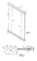
Figure 1 is a perspective view of a first present preferred embodiment of my window covering illustrating the window covering material in an extended position. -
Figure 2 is a fragmentary view of the first present preferred embodiment illustrating the spring motor cord and lift cord attached to the connector. -
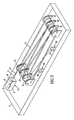
Figure 3 is a top perspective view of the first present preferred embodiment illustrating the pulleys, spring motor, first present preferred deformable connector and cord path wherein a portion of the cord path is shown in chain line. -
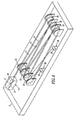
Figure 4 is a perspective view similar toFigure 3 illustrating the connector and spring motor cord of the first present preferred embodiment in an initial position that corresponds with the window covering material being in an extended position. -
Figure 5 is a perspective view similar toFigures 3 and4 illustrating the connector and spring motor cord of the first present preferred embodiment in a position that corresponds with the window covering material being in a second extended position. -
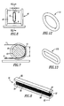
Figure 6 is a rear elevated perspective view of a first present preferred connector passing over the first present preferred pulley. -
Figure 7 is a cross sectional view taken along line VII-VII inFigure 6 of the first present preferred connector passing over the first present preferred pulley. -
Figure 8 is a perspective view of a second present preferred embodiment of my window covering illustrating the window covering material in a fully retracted position. -
Figure 9 is a top perspective view of the first present preferred embodiment illustrating the pulleys, spring motor, first present preferred deformable connector and cord path wherein a portion of the cord path is shown in chain line. -
Figure 10 is a perspective view similar toFigure 9 illustrating the connector and spring motor cord of the first present preferred embodiment in an initial position that corresponds with the window covering material being in an extended position. -
Figure 11 is a perspective view similar toFigures 9 and10 illustrating the connector and spring motor cord of the first present preferred embodiment in a position that corresponds with the window covering material being in a second extended position. -
Figure 12 is a perspective view of the first present preferred deformable connector. -
Figure 13 is a perspective view of a second present preferred deformable connector. - Referring to
Figure 1 , a first present preferred embodiment of my window covering 1 includes a headrail 3, abottom rail 5,window covering material 7 positioned between the headrail 3 andbottom rail 5. Alift cord 9 has a first end attached to the bottom rail adjacent one end of thebottom rail 5 and a second end attached to the bottom rail adjacent the opposite end of thebottom rail 5. Thelift cord 9 extends through the window covering material and into the headrail 3. - The headrail 3 houses a lift system. The lift system includes a
spring motor 15 that is operatively connected to thelift cord 9. Thespring motor 15 includes afirst spool 19 and asecond spool 21. Aspring 17 is connected to bothspools spools spring motor 15 also includes aspring motor cord 11 that is attached to a spool (not shown) such that thespools spring motor cord 11 is extended or retracted from this spool. During retraction of thespring motor cord 11, thespring motor cord 11 may be wound about the spool. During extension of thespring motor cord 11, thespring motor cord 11 may be unwound from the spool. - It should be appreciated that the
spring motor 15 may be any type of spring motor or interconnected spring motors known to those skilled in the art. For example, spring motors of the type disclosed inU.S. Patent No. 6,234,236 or other spring motors may be used in embodiments of my window covering. - As may be best appreciated from
Figure 2 , thespring motor cord 11 is attached to a first end of adeformable connector 13. Thedeformable connector 13 is also attached to a middle portion of thelift cord 9. Preferably, thespring motor cord 11 andlift cord 9 are looped about opposite ends of theconnector 13 to attach those cords to theconnector 13. Thelift cord 9 andspring motor cord 11 exert forces that act on opposite ends of theconnector 13, which deforms the connector so it is stretched to a length L and a width W. The width W is sufficiently narrow to permit the connector to pass over a pulley. - As shown in
Figures 3-5 , the lift system of the window covering 1 may include a plurality of pulleys adjacent the headrail 3. The pulleys may include afirst pulley 23, asecond pulley 27 and athird pulley 31 that are all aligned with each other adjacent one end of the headrail. Afourth pulley 25,fifth pulley 29 andsixth pulley 33 may be positioned opposite the first threepulleys Rollers roller respective hole lift cord 9 passes over the rollers, through theholes window covering material 7. - The
deformable connector 13 is configured such that thedeformed connector 13 can pass along pulleys positioned in the headrail 3 of the window covering. For example, a portion of thespring motor cord 11, thedeformable connector 13 and a portion of thelift cord 9 may travel from the initial position, which corresponds to thewindow covering material 7 being in a fully retracted position, to a second position shown inFigure 4 , which corresponds with thewindow covering material 7 being in an extended position. - In moving from the initial position to the second position, the
connector 13, portion of thelift cord 9 and portion of thespring motor cord 11 pass abovepulley 23 towardpulley 25. The cord portions andconnector 13 then travel alongpulley 25 such that theconnector 13 and cord portions reverse direction and move towardpulley 23. Theconnector 13 and cord portions then move alongpulley 23 and reverse direction a second time such that the cord portions andconnector 13 move towardpulley 29 until stopping at the second position shown inFigure 4 . - The
window covering material 7 may also be extended from either the fully retracted position or the extended position to another extended position or a fully extended position as may be appreciated fromFigure 5 . When thewindow covering material 7 is further extended, from the extended position shown inFigure 4 , theconnector 13 and portions ofspring motor cord 11 andlift cord 9 can move from the second position towardpulley 29, alongpulley 29 such that the direction of movement is reversed so that theconnector 13 and cord portions move towardpulley 27, alongpulley 27 such that theconnector 13 and cord portions reverse direction again and move towardpulley 33 before stopping at the position shown inFigure 5 betweenpulleys connector 13 is configured to move along the cord path and pass along the pulleys during retraction of the window covering material as well. - Because the
connector 13 is deformable, theconnector 13 may deform to a first deformed configuration when attached to thespring motor cord 11 andlift cord 9 and deform a greater extent when passing over, or passing along, a pulley due to the additional force that may be exerted on theconnector 13 from such movement. As may be appreciated fromFigures 6 and 7 , theconnector 13 may pass over thesurface 43 of apulley 41, which defines the circumference of thepulley 41. Passing oversurface 43 may further deform theconnector 13 into a more elongated configuration having alength 1, which is longer than length L, and/or a more narrow width w that is narrower than width W. As may be appreciated fromFigures 6 and 7 , theconnector 13 may deform as it passes over thepulley 41 such that it has a curved shape or deforms into a curved shape as the connector passes along thesurface 43 of thepulley 41. - In some embodiments of my window covering, the
connector 13 may have a first deformed state that provides a width W that is about as wide as the width of thepulley surface 43, but is configured to deform to a second width when passing along thepulley 41. Such deformation may make it easier for the connector to pass along thepulley 41 and help ensure that the connector properly aligns with each pulley when traveling along the cord path defined by the pulleys in the lift system. Once theconnector 13 has passed along thepulley 41 and no longer engages thesurface 43 of thepulley 41, it may become less deformed such that the dimensions of theconnector 13 return to the initially deformed length L and width W. - Embodiments of my window covering may also include cord operated shades or blinds that include at least one cord lock. For instance, one embodiment of my window covering 51 may include a
headrail 53, abottom rail 55,window covering material 57 positioned between theheadrail 53 andbottom rail 55 andlift cords 59 that pass through thewindow covering material 57 to theheadrail 53. Thebottom rail 55 may be attached to thewindow covering material 57 and/or thelift cords 59. Acord lock 61 is positioned adjacent one end of theheadrail 53 and has anoperator cord 63 that extends from outside the headrail through thecord lock 61 and into theheadrail 53. - A number of pulleys may be aligned within the headrail. A first pulley, 71,
second pulley 74 andthird pulley 78 may be aligned with each other adjacent a first end of theheadrail 53 near thecord lock 61. Afourth pulley 73 andfifth pulley 77 may be positioned opposite the first, second andthird pulleys headrail 53. Thelift cords 59 pass through holes in the headrail along rollers and around the pulleys to adeformable connector 13. Thelift cords 59 are attached to one side of thedeformable connector 13. Aportion 65 of theoperator cord 63 extends through thecord lock 61 and to thedeformable connector 13. Theportion 65 of theoperator cord 63 is attached to thedeformable connector 13 at a side that is opposite the side at which thelift cords 59 are attached to theconnector 13. Thelift cords 59 andoperator cord portion 65 may be tied to theconnector 13 or otherwise fastened to theconnector 13. - As may be appreciated from
Figures 9-11 , theconnector 13 is sized and configured such theconnector 13 deforms sufficiently for it to pass along at least one of the pulleys when thewindow covering material 57 is being retracted or extended. Theconnector 13 deforms similarly to the deformation of theconnector 13 in the first presentpreferred embodiment 1, discussed above, and may have a cord path that is defined by thepulleys connector 13 may pass along pulleys 71 and 73 when thewindow covering material 57 is being extended to one of many different extended positions, as illustrated inFigure 10 , or pass along pulleys 71, 73, 74 and 77 when thewindow covering material 57 is extended to a fully extended position, as illustrated inFigure 11 . It should be understood that one ormore posts 72, which are shown in dotted line inFigure 9 , or other structures may also be positioned adjacent the headrail to help define a cord path or a portion of the cord path. - The
connector 13 may have an initial size and configuration that is different than its configuration when attached to thespring motor cord 11 oroperator cord portion 65 and one or more lift cords. This initial size of the connector may be its undeformed size and configuration, which can include a width dimension that is substantially larger than the width of any pulley. The forces applied to theconnector 13 by the one or more lift cords and operator cord portion or spring motor cord preferably provides sufficient force to deform theconnector 13 so it at least has a width W. In some embodiments, the width W will be sufficient for theconnector 13 to be sized for passing along at least one pulley in the window covering lift system when the window covering is extended from a fully retracted position to a fully extended position. In other embodiments, the width W is sufficient for theconnector 13 to pass along multiple pulleys during extension and retraction of the window covering material. - The use of the
deformable connector 13 substantially reduces, if not eliminates, the binding problems that can occur in other window covering lift systems that may include a direct attachment, such as a knot, to attach one or more lift cords to a spring motor cord. Moreover, the use of such a connector permits lift systems to be configured so they do not require the collection of lift cords or other cords about any spools or shafts located in or adjacent a headrail or bottom rail, such as the lift systems disclosed inU.S. Patent Nos. 2,687,769 or6,325,131 , which can also help avoid any binding or "hang up" problems. - It should be understood that the connector may have various initial shapes or sizes. For example, the connector could be a generally circular ring, such as the
connector 13 shown inFigure 12 or be a generally oval shaped ring, such asring 113 shown inFigure 13 . The connector may be composed of numerous different deformable materials. Preferably, the connector is composed of rubber, other elastomers or a deformable plastic and is formed as a unitary structure. - Of course, other variations of the present preferred embodiments discussed above may be made. For example, embodiments of my window covering can include pleated shades, cellular shades, venetian blinds, roman shades, top down bottom up shades and other shades or blinds. As another example, embodiments of my window covering can include more than one or two lift cords that extend from the window covering material to the headrail rail. As yet another example, embodiments of my window covering may have the lift system located within the bottom rail.
- While certain present preferred embodiments of my window covering and certain embodiments of methods of practicing the same have been shown and described, it is to be distinctly understood that the invention is not limited thereto but may be otherwise variously embodied and practiced within the scope of the following claims.
Claims (20)
- A window covering comprising:a first rail, the first rail having a first end and a second end opposite the first end;window covering material adjacent the first rail, the window covering material moveable from a retracted position to an extended position;at least one lift cord extending through the window covering material to the headrail;a second rail attached to at least one of the at least one lift cord and the window covering material;a plurality of pulleys positioned adjacent the first rail;at least one spring motor adjacent the first rail,at least one spring motor cord extending from the at least one spring motor, the at least one spring motor cord configured to extend away from the at least one spring motor along a path defined by at least one of the plurality of pulleys when the window covering material is extended away from the first rail to the extended position and configured to be retracted toward the at least one spring motor along the path when the window covering material is retracted from the extended position to the retracted position; anda deformable connector attached to the at least one spring motor cord and to the at least one lift cord, the at least one connector sized and configured to deform such that the connector has a size and shape sufficient for the at least one spring motor cord, connector and a portion of the at least one lift cord to pass over at least one of the plurality of pulleys during movement along the path; and the connector assuming a curved shape as the connector passes over the at least one of the plurality of pulleys.
- The window covering of claim 1 wherein the deformable connector is comprised of one of a ring having a generally oval shaped body and ring having a generally circular body.
- The window covering of claim 1 wherein each pulley has a surface around which the connector passes along when traveling along the path, the deformable connector configured to deform to a first length when the connector is not passing along the surface of any of the pulleys and configured to deform to a second length when the connector passes along the surface of any of the pulleys, the first length being less than the second length.
- The window covering of claim 1 wherein the first rail is a headrail and the second rail is a bottom rail.
- The window covering of claim 1 wherein the at least one lift cord is looped about the connector to attach the at least one lift cord to the connector.
- The window covering of claim 1 wherein the at least one spring motor cord is looped about the connector to attach the at least one spring motor cord to the connector.
- The window covering of claim 1 wherein the plurality of pulleys is comprised of a first pulley, a second pulley and a third pulley aligned with each other adjacent the first end of the first rail and a fourth pulley, fifth pulley and sixth pulley aligned with each other adjacent the second end of the first rail.
- The window covering of claim 7 wherein the path is defined by movement of the at least one spring motor cord and the deformable connector to move from adjacent the at least one spring motor to the first pulley, from the first pulley to the fourth pulley, from the fourth pulley to the second pulley and from the second pulley to the fifth pulley or the sixth pulley when the window covering material is extended from the retracted position to the extended position.
- The window covering of claim 1 wherein the plurality of pulleys comprises three pulleys connected to a first pulley mount adjacent the first end of the first rail and three pulleys connected to a second pulley mount adjacent the second end of the first rail.
- The window covering of claim 1 wherein the at least one spring motor cord, connector and a portion of the at least one lift cord pass along at least one of the plurality of pulleys during movement along the path such that movement of the at least one spring motor cord and connector is reversed from movement toward the first end of the first rail to movement toward the second end of the first rail while moving along the path when the window covering material is retracted from the extended position to the retracted position or extended from the retracted potion to the extended position.
- A window covering comprising:a first rail, the first rail having a first end and a second end opposite the first end;window covering material adjacent the first rail, the window covering material moveable from a retracted position to an extended position;at least one lift cord extending through the window covering material to the headrail;a second rail attached to at least one of the at least one lift cord and the window covering material;a plurality of pulleys positioned adjacent the first rail;a cord lock adjacent the first rail,at least one operator cord passing through the cord lock;a deformable connector attached to a portion of the at least one lift cord and a portion of the operator cord; the operator cord and at least one lift cord each of a length such that the connector passes along at least one of the pulleys when the window covering material is moved to the extended position, the at least one deformable connector sized and configured to deform such that the connector has a size and shape sufficient for the portion of the at least one operator cord, connector and portion of the at least one lift cord to pass over at least one of the plurality of pulleys when the window covering material is moved to the extended position, the connector assuming a curved shape as the connector passes over the at least one of the pluarlity of pulleys.
- The window covering of claim 11 wherein the connector is comprised of one of a ring having a generally oval shaped body and a ring having a generally circular body.
- The window covering of claim 11 wherein each pulley has a surface around which the connector passes along when traveling along the path, the deformable connector configured to deform to a first length when the connector is not passing along the surface of any of the pulleys and configured to deform to a second length when the connector passes along the surface of any of the pulleys, the second length being greater than the first length.
- The window covering of claim 11 wherein the first rail is a headrail and the second rail is a bottom rail.
- The window covering of claim 11 wherein the at least one lift cord is looped about the connector to attach the at least one lift cord to the connector.
- The window covering of claim 11 wherein the first portion of the at least one operator cord is looped about the connector to attach the first portion of the at least one operator cord to the connector.
- The window covering of claim 11 wherein the plurality of pulleys is comprised of a first pulley, a second pulley and a third pulley aligned with each other adjacent the first end of the first rail and a fourth pulley, fifth pulley and sixth pulley aligned with each other adjacent the second end of the first rail.
- The window covering of claim 17 wherein the path is defined by movement of the first portion of the at least one operator cord and the connector to move from adjacent the cord lock to the first pulley, from the first pulley to the fourth pulley, from the fourth pulley to the second pulley and from the second pulley to the fifth pulley or the sixth pulley when the window covering material is extended from the retracted position to the extended position.
- The window covering of claim 11 wherein the plurality of pulleys comprises three pulleys connected to a first pulley mount adjacent the first end of the first rail and three pulleys connected to a second pulley mount adjacent the second end of the first rail.
- The window covering of claim 11 wherein the first portion of the at least one operator cord, connector and a portion of the at least one lift cord pass along at least one of the plurality of pulleys during movement along the path such that movement of the first portion of the at least one operator cord and connector is reversed from movement toward the first end of the first rail to movement toward the second end of the first rail while moving along the path when the window covering material is retracted from the extended position to the retracted position or extended from the retracted potion to the extended position.
Applications Claiming Priority (1)
| Application Number | Priority Date | Filing Date | Title |
|---|---|---|---|
| US12/184,287 US9140060B2 (en) | 2008-08-01 | 2008-08-01 | Window covering having at least one deformable connector |
Publications (3)
| Publication Number | Publication Date |
|---|---|
| EP2149667A2 true EP2149667A2 (en) | 2010-02-03 |
| EP2149667A3 EP2149667A3 (en) | 2012-12-19 |
| EP2149667B1 EP2149667B1 (en) | 2014-01-08 |
Family
ID=41361299
Family Applications (1)
| Application Number | Title | Priority Date | Filing Date |
|---|---|---|---|
| EP08165163.0A Not-in-force EP2149667B1 (en) | 2008-08-01 | 2008-09-25 | Window covering having at least one deformable connector |
Country Status (3)
| Country | Link |
|---|---|
| US (1) | US9140060B2 (en) |
| EP (1) | EP2149667B1 (en) |
| CA (1) | CA2639632C (en) |
Cited By (5)
| Publication number | Priority date | Publication date | Assignee | Title |
|---|---|---|---|---|
| US9192267B2 (en) | 2012-10-11 | 2015-11-24 | Roman Tsibulevskiy | Shower curtain technologies |
| US9949597B2 (en) | 2012-10-11 | 2018-04-24 | Roman Tsibulevskiy | Partition technologies |
| US9955825B2 (en) | 2012-10-11 | 2018-05-01 | Roman Tsibulevskiy | Partition technologies |
| US10292538B2 (en) | 2012-10-11 | 2019-05-21 | Roman Tsibulevskiy | Partition technologies |
| US11083344B2 (en) | 2012-10-11 | 2021-08-10 | Roman Tsibulevskiy | Partition technologies |
Families Citing this family (3)
| Publication number | Priority date | Publication date | Assignee | Title |
|---|---|---|---|---|
| US9510711B2 (en) | 2012-10-11 | 2016-12-06 | Roman Tsibulevskiy | Partition technologies |
| US9103157B2 (en) * | 2013-04-13 | 2015-08-11 | Qmotion Incorporated | Spring counterbalance apparatus and method |
| TWM499563U (en) * | 2014-08-27 | 2015-04-21 | Crucibleware Company Ltd | Light homogenizing structure and light homogenizing module |
Citations (12)
| Publication number | Priority date | Publication date | Assignee | Title |
|---|---|---|---|---|
| US2687769A (en) | 1952-05-09 | 1954-08-31 | Seymour P Gershuny | Venetian blind |
| US4819381A (en) | 1986-02-14 | 1989-04-11 | Nissan Motor Co., Ltd. | Weatherstrip for vehicle closures |
| US5193601A (en) | 1988-12-22 | 1993-03-16 | Comfortex Corporation | Multi-cellular collapsible shade |
| US5482750A (en) | 1991-01-02 | 1996-01-09 | Hunter Douglas Inc. | Multiple cell honeycomb insulating panel and method of hanging |
| US6234236B1 (en) | 1994-04-06 | 2001-05-22 | Newell Operating Company | Cordless balanced window covering |
| US6325131B1 (en) | 1999-04-16 | 2001-12-04 | Hunter Douglas Industries B.V. | Cord spool |
| US6644372B2 (en) | 2001-03-22 | 2003-11-11 | Ren Judkins | Cordless blind |
| US20040129390A1 (en) | 1997-11-04 | 2004-07-08 | Toti Andrew J | Spring drive system and window cover |
| US6837294B2 (en) | 2003-02-10 | 2005-01-04 | Zipshade Industrial (B.V.I.) Corp. | Pull down, push up, shade assembly |
| US6991020B1 (en) | 2003-02-10 | 2006-01-31 | Zipshade Industrial (B.V.I.) Corp. | Pull down, push up, shade assembly |
| US7159634B1 (en) | 1995-03-29 | 2007-01-09 | Ren Judkins | Pleated and cellular materials |
| US20070163727A1 (en) | 2003-02-10 | 2007-07-19 | Zipshade Industrial (B.V.I.) Corp. | Window Blinds with Gears |
Family Cites Families (6)
| Publication number | Priority date | Publication date | Assignee | Title |
|---|---|---|---|---|
| US13251A (en) | 1855-07-17 | Window-blind | ||
| GB1070526A (en) * | 1963-06-07 | 1967-06-01 | Nat Distillers Chem Corp | Tilt mechanism for a venetian blind assembly |
| US3403427A (en) * | 1965-03-15 | 1968-10-01 | Asseo Albert | Resilient fastening device |
| US6691020B2 (en) * | 2001-06-19 | 2004-02-10 | Ford Global Technologies, Llc | Method and system for optimizing purge of exhaust gas constituent stored in an emission control device |
| US8245756B2 (en) * | 2003-02-10 | 2012-08-21 | Li-Ming Cheng | Pull down, push up, shade apparatus |
| FR2899268B3 (en) * | 2006-03-28 | 2008-06-20 | Henry Lin | STORE WINDING SYSTEM |
-
2008
- 2008-08-01 US US12/184,287 patent/US9140060B2/en not_active Expired - Fee Related
- 2008-09-18 CA CA2639632A patent/CA2639632C/en not_active Expired - Fee Related
- 2008-09-25 EP EP08165163.0A patent/EP2149667B1/en not_active Not-in-force
Patent Citations (12)
| Publication number | Priority date | Publication date | Assignee | Title |
|---|---|---|---|---|
| US2687769A (en) | 1952-05-09 | 1954-08-31 | Seymour P Gershuny | Venetian blind |
| US4819381A (en) | 1986-02-14 | 1989-04-11 | Nissan Motor Co., Ltd. | Weatherstrip for vehicle closures |
| US5193601A (en) | 1988-12-22 | 1993-03-16 | Comfortex Corporation | Multi-cellular collapsible shade |
| US5482750A (en) | 1991-01-02 | 1996-01-09 | Hunter Douglas Inc. | Multiple cell honeycomb insulating panel and method of hanging |
| US6234236B1 (en) | 1994-04-06 | 2001-05-22 | Newell Operating Company | Cordless balanced window covering |
| US7159634B1 (en) | 1995-03-29 | 2007-01-09 | Ren Judkins | Pleated and cellular materials |
| US20040129390A1 (en) | 1997-11-04 | 2004-07-08 | Toti Andrew J | Spring drive system and window cover |
| US6325131B1 (en) | 1999-04-16 | 2001-12-04 | Hunter Douglas Industries B.V. | Cord spool |
| US6644372B2 (en) | 2001-03-22 | 2003-11-11 | Ren Judkins | Cordless blind |
| US6837294B2 (en) | 2003-02-10 | 2005-01-04 | Zipshade Industrial (B.V.I.) Corp. | Pull down, push up, shade assembly |
| US6991020B1 (en) | 2003-02-10 | 2006-01-31 | Zipshade Industrial (B.V.I.) Corp. | Pull down, push up, shade assembly |
| US20070163727A1 (en) | 2003-02-10 | 2007-07-19 | Zipshade Industrial (B.V.I.) Corp. | Window Blinds with Gears |
Cited By (7)
| Publication number | Priority date | Publication date | Assignee | Title |
|---|---|---|---|---|
| US9192267B2 (en) | 2012-10-11 | 2015-11-24 | Roman Tsibulevskiy | Shower curtain technologies |
| US9949597B2 (en) | 2012-10-11 | 2018-04-24 | Roman Tsibulevskiy | Partition technologies |
| US9955825B2 (en) | 2012-10-11 | 2018-05-01 | Roman Tsibulevskiy | Partition technologies |
| US10292538B2 (en) | 2012-10-11 | 2019-05-21 | Roman Tsibulevskiy | Partition technologies |
| US11083344B2 (en) | 2012-10-11 | 2021-08-10 | Roman Tsibulevskiy | Partition technologies |
| US11529025B2 (en) | 2012-10-11 | 2022-12-20 | Roman Tsibulevskiy | Technologies for computing |
| US11882967B2 (en) | 2012-10-11 | 2024-01-30 | Roman Tsibulevskiy | Technologies for computing |
Also Published As
| Publication number | Publication date |
|---|---|
| US9140060B2 (en) | 2015-09-22 |
| CA2639632A1 (en) | 2010-02-01 |
| EP2149667B1 (en) | 2014-01-08 |
| CA2639632C (en) | 2015-11-24 |
| US20100024994A1 (en) | 2010-02-04 |
| EP2149667A3 (en) | 2012-12-19 |
Similar Documents
| Publication | Publication Date | Title |
|---|---|---|
| EP2131008B1 (en) | Window Covering | |
| EP2149667B1 (en) | Window covering having at least one deformable connector | |
| TW380044B (en) | Cordless cellular and pleated shade | |
| US20130248125A1 (en) | Window Covering Having a Lift System Utilizing Conical Spools | |
| EP2469008B1 (en) | Window covering | |
| US8708023B2 (en) | Cordless blind assembly | |
| US20100126673A1 (en) | Window Covering Having at Least One Cord Release Device | |
| EP2472049A2 (en) | Window covering with cord shrouds | |
| CA2682579C (en) | A window covering | |
| CA2953344C (en) | Devices and systems for accumulating lift cords used to lift architectural opening coverings | |
| US9759009B2 (en) | Window covering | |
| US20120305199A1 (en) | Window Covering and Method of Making the Same | |
| US9366079B1 (en) | Cord safety device for window coverings | |
| EP2675980B1 (en) | Stiffened pull cord for architectural coverings | |
| CN211448457U (en) | Rope threading component for curtain and curtain using same | |
| EP2221443B1 (en) | A window covering | |
| EP2565362A1 (en) | Loop cord tension device for window coverings | |
| DE10126812C2 (en) | Roman blind with winding elements attached to a shaft | |
| CN211692231U (en) | A wire rope handling component and (window) curtain for (window) curtain | |
| EP1840319A2 (en) | Coiling device of a roller blind | |
| DE10126813C2 (en) | Roman blind with a single pull cord | |
| US9810018B1 (en) | Cord safety device for window coverings | |
| EP2514910B1 (en) | Window covering | |
| CA2874872A1 (en) | Cord safety device for window coverings | |
| ITBO990459A1 (en) | VENETIAN CURTAIN FRAME WITH BUILT-IN GUIDES. |
Legal Events
| Date | Code | Title | Description |
|---|---|---|---|
| PUAI | Public reference made under article 153(3) epc to a published international application that has entered the european phase |
Free format text: ORIGINAL CODE: 0009012 |
|
| AK | Designated contracting states |
Kind code of ref document: A2 Designated state(s): AT BE BG CH CY CZ DE DK EE ES FI FR GB GR HR HU IE IS IT LI LT LU LV MC MT NL NO PL PT RO SE SI SK TR |
|
| AX | Request for extension of the european patent |
Extension state: AL BA MK RS |
|
| RAP1 | Party data changed (applicant data changed or rights of an application transferred) |
Owner name: WHOLE SPACE INDUSTRIES LTD |
|
| PUAL | Search report despatched |
Free format text: ORIGINAL CODE: 0009013 |
|
| AK | Designated contracting states |
Kind code of ref document: A3 Designated state(s): AT BE BG CH CY CZ DE DK EE ES FI FR GB GR HR HU IE IS IT LI LT LU LV MC MT NL NO PL PT RO SE SI SK TR |
|
| AX | Request for extension of the european patent |
Extension state: AL BA MK RS |
|
| RIC1 | Information provided on ipc code assigned before grant |
Ipc: E06B 9/262 20060101ALN20121113BHEP Ipc: E06B 9/322 20060101AFI20121113BHEP |
|
| 17P | Request for examination filed |
Effective date: 20130614 |
|
| RBV | Designated contracting states (corrected) |
Designated state(s): AT BE BG CH CY CZ DE DK EE ES FI FR GB GR HR HU IE IS IT LI LT LU LV MC MT NL NO PL PT RO SE SI SK TR |
|
| GRAP | Despatch of communication of intention to grant a patent |
Free format text: ORIGINAL CODE: EPIDOSNIGR1 |
|
| RIC1 | Information provided on ipc code assigned before grant |
Ipc: E06B 9/262 20060101ALN20130710BHEP Ipc: E06B 9/322 20060101AFI20130710BHEP |
|
| AKX | Designation fees paid |
Designated state(s): AT BE BG CH CY CZ DE DK EE ES FI FR GB GR HR HU IE IS IT LI LT LU LV MC MT NL NO PL PT RO SE SI SK TR |
|
| INTG | Intention to grant announced |
Effective date: 20130805 |
|
| GRAS | Grant fee paid |
Free format text: ORIGINAL CODE: EPIDOSNIGR3 |
|
| GRAA | (expected) grant |
Free format text: ORIGINAL CODE: 0009210 |
|
| AK | Designated contracting states |
Kind code of ref document: B1 Designated state(s): AT BE BG CH CY CZ DE DK EE ES FI FR GB GR HR HU IE IS IT LI LT LU LV MC MT NL NO PL PT RO SE SI SK TR |
|
| REG | Reference to a national code |
Ref country code: GB Ref legal event code: FG4D |
|
| REG | Reference to a national code |
Ref country code: CH Ref legal event code: EP |
|
| REG | Reference to a national code |
Ref country code: IE Ref legal event code: FG4D |
|
| REG | Reference to a national code |
Ref country code: AT Ref legal event code: REF Ref document number: 648887 Country of ref document: AT Kind code of ref document: T Effective date: 20140215 |
|
| REG | Reference to a national code |
Ref country code: DE Ref legal event code: R096 Ref document number: 602008029727 Country of ref document: DE Effective date: 20140220 |
|
| REG | Reference to a national code |
Ref country code: NL Ref legal event code: T3 |
|
| REG | Reference to a national code |
Ref country code: AT Ref legal event code: MK05 Ref document number: 648887 Country of ref document: AT Kind code of ref document: T Effective date: 20140108 |
|
| REG | Reference to a national code |
Ref country code: LT Ref legal event code: MG4D |
|
| PG25 | Lapsed in a contracting state [announced via postgrant information from national office to epo] |
Ref country code: LT Free format text: LAPSE BECAUSE OF FAILURE TO SUBMIT A TRANSLATION OF THE DESCRIPTION OR TO PAY THE FEE WITHIN THE PRESCRIBED TIME-LIMIT Effective date: 20140108 Ref country code: IS Free format text: LAPSE BECAUSE OF FAILURE TO SUBMIT A TRANSLATION OF THE DESCRIPTION OR TO PAY THE FEE WITHIN THE PRESCRIBED TIME-LIMIT Effective date: 20140508 Ref country code: NO Free format text: LAPSE BECAUSE OF FAILURE TO SUBMIT A TRANSLATION OF THE DESCRIPTION OR TO PAY THE FEE WITHIN THE PRESCRIBED TIME-LIMIT Effective date: 20140408 |
|
| PG25 | Lapsed in a contracting state [announced via postgrant information from national office to epo] |
Ref country code: CY Free format text: LAPSE BECAUSE OF FAILURE TO SUBMIT A TRANSLATION OF THE DESCRIPTION OR TO PAY THE FEE WITHIN THE PRESCRIBED TIME-LIMIT Effective date: 20140108 Ref country code: ES Free format text: LAPSE BECAUSE OF FAILURE TO SUBMIT A TRANSLATION OF THE DESCRIPTION OR TO PAY THE FEE WITHIN THE PRESCRIBED TIME-LIMIT Effective date: 20140108 Ref country code: PT Free format text: LAPSE BECAUSE OF FAILURE TO SUBMIT A TRANSLATION OF THE DESCRIPTION OR TO PAY THE FEE WITHIN THE PRESCRIBED TIME-LIMIT Effective date: 20140508 Ref country code: SE Free format text: LAPSE BECAUSE OF FAILURE TO SUBMIT A TRANSLATION OF THE DESCRIPTION OR TO PAY THE FEE WITHIN THE PRESCRIBED TIME-LIMIT Effective date: 20140108 Ref country code: AT Free format text: LAPSE BECAUSE OF FAILURE TO SUBMIT A TRANSLATION OF THE DESCRIPTION OR TO PAY THE FEE WITHIN THE PRESCRIBED TIME-LIMIT Effective date: 20140108 Ref country code: FI Free format text: LAPSE BECAUSE OF FAILURE TO SUBMIT A TRANSLATION OF THE DESCRIPTION OR TO PAY THE FEE WITHIN THE PRESCRIBED TIME-LIMIT Effective date: 20140108 |
|
| PG25 | Lapsed in a contracting state [announced via postgrant information from national office to epo] |
Ref country code: BE Free format text: LAPSE BECAUSE OF FAILURE TO SUBMIT A TRANSLATION OF THE DESCRIPTION OR TO PAY THE FEE WITHIN THE PRESCRIBED TIME-LIMIT Effective date: 20140108 Ref country code: HR Free format text: LAPSE BECAUSE OF FAILURE TO SUBMIT A TRANSLATION OF THE DESCRIPTION OR TO PAY THE FEE WITHIN THE PRESCRIBED TIME-LIMIT Effective date: 20140108 Ref country code: LV Free format text: LAPSE BECAUSE OF FAILURE TO SUBMIT A TRANSLATION OF THE DESCRIPTION OR TO PAY THE FEE WITHIN THE PRESCRIBED TIME-LIMIT Effective date: 20140108 |
|
| REG | Reference to a national code |
Ref country code: DE Ref legal event code: R097 Ref document number: 602008029727 Country of ref document: DE |
|
| PG25 | Lapsed in a contracting state [announced via postgrant information from national office to epo] |
Ref country code: RO Free format text: LAPSE BECAUSE OF FAILURE TO SUBMIT A TRANSLATION OF THE DESCRIPTION OR TO PAY THE FEE WITHIN THE PRESCRIBED TIME-LIMIT Effective date: 20140108 Ref country code: EE Free format text: LAPSE BECAUSE OF FAILURE TO SUBMIT A TRANSLATION OF THE DESCRIPTION OR TO PAY THE FEE WITHIN THE PRESCRIBED TIME-LIMIT Effective date: 20140108 Ref country code: DK Free format text: LAPSE BECAUSE OF FAILURE TO SUBMIT A TRANSLATION OF THE DESCRIPTION OR TO PAY THE FEE WITHIN THE PRESCRIBED TIME-LIMIT Effective date: 20140108 Ref country code: CZ Free format text: LAPSE BECAUSE OF FAILURE TO SUBMIT A TRANSLATION OF THE DESCRIPTION OR TO PAY THE FEE WITHIN THE PRESCRIBED TIME-LIMIT Effective date: 20140108 |
|
| PLBE | No opposition filed within time limit |
Free format text: ORIGINAL CODE: 0009261 |
|
| STAA | Information on the status of an ep patent application or granted ep patent |
Free format text: STATUS: NO OPPOSITION FILED WITHIN TIME LIMIT |
|
| PG25 | Lapsed in a contracting state [announced via postgrant information from national office to epo] |
Ref country code: PL Free format text: LAPSE BECAUSE OF FAILURE TO SUBMIT A TRANSLATION OF THE DESCRIPTION OR TO PAY THE FEE WITHIN THE PRESCRIBED TIME-LIMIT Effective date: 20140108 Ref country code: SK Free format text: LAPSE BECAUSE OF FAILURE TO SUBMIT A TRANSLATION OF THE DESCRIPTION OR TO PAY THE FEE WITHIN THE PRESCRIBED TIME-LIMIT Effective date: 20140108 |
|
| 26N | No opposition filed |
Effective date: 20141009 |
|
| REG | Reference to a national code |
Ref country code: DE Ref legal event code: R097 Ref document number: 602008029727 Country of ref document: DE Effective date: 20141009 |
|
| PG25 | Lapsed in a contracting state [announced via postgrant information from national office to epo] |
Ref country code: LU Free format text: LAPSE BECAUSE OF FAILURE TO SUBMIT A TRANSLATION OF THE DESCRIPTION OR TO PAY THE FEE WITHIN THE PRESCRIBED TIME-LIMIT Effective date: 20140925 Ref country code: MC Free format text: LAPSE BECAUSE OF FAILURE TO SUBMIT A TRANSLATION OF THE DESCRIPTION OR TO PAY THE FEE WITHIN THE PRESCRIBED TIME-LIMIT Effective date: 20140108 |
|
| REG | Reference to a national code |
Ref country code: CH Ref legal event code: PL |
|
| PG25 | Lapsed in a contracting state [announced via postgrant information from national office to epo] |
Ref country code: SI Free format text: LAPSE BECAUSE OF FAILURE TO SUBMIT A TRANSLATION OF THE DESCRIPTION OR TO PAY THE FEE WITHIN THE PRESCRIBED TIME-LIMIT Effective date: 20140108 |
|
| REG | Reference to a national code |
Ref country code: IE Ref legal event code: MM4A |
|
| PG25 | Lapsed in a contracting state [announced via postgrant information from national office to epo] |
Ref country code: LI Free format text: LAPSE BECAUSE OF NON-PAYMENT OF DUE FEES Effective date: 20140930 Ref country code: CH Free format text: LAPSE BECAUSE OF NON-PAYMENT OF DUE FEES Effective date: 20140930 |
|
| PG25 | Lapsed in a contracting state [announced via postgrant information from national office to epo] |
Ref country code: IE Free format text: LAPSE BECAUSE OF NON-PAYMENT OF DUE FEES Effective date: 20140925 |
|
| REG | Reference to a national code |
Ref country code: FR Ref legal event code: PLFP Year of fee payment: 8 |
|
| PG25 | Lapsed in a contracting state [announced via postgrant information from national office to epo] |
Ref country code: BG Free format text: LAPSE BECAUSE OF FAILURE TO SUBMIT A TRANSLATION OF THE DESCRIPTION OR TO PAY THE FEE WITHIN THE PRESCRIBED TIME-LIMIT Effective date: 20140108 |
|
| PG25 | Lapsed in a contracting state [announced via postgrant information from national office to epo] |
Ref country code: GR Free format text: LAPSE BECAUSE OF FAILURE TO SUBMIT A TRANSLATION OF THE DESCRIPTION OR TO PAY THE FEE WITHIN THE PRESCRIBED TIME-LIMIT Effective date: 20140409 Ref country code: MT Free format text: LAPSE BECAUSE OF FAILURE TO SUBMIT A TRANSLATION OF THE DESCRIPTION OR TO PAY THE FEE WITHIN THE PRESCRIBED TIME-LIMIT Effective date: 20140108 |
|
| PG25 | Lapsed in a contracting state [announced via postgrant information from national office to epo] |
Ref country code: HU Free format text: LAPSE BECAUSE OF FAILURE TO SUBMIT A TRANSLATION OF THE DESCRIPTION OR TO PAY THE FEE WITHIN THE PRESCRIBED TIME-LIMIT; INVALID AB INITIO Effective date: 20080925 Ref country code: TR Free format text: LAPSE BECAUSE OF FAILURE TO SUBMIT A TRANSLATION OF THE DESCRIPTION OR TO PAY THE FEE WITHIN THE PRESCRIBED TIME-LIMIT Effective date: 20140108 |
|
| REG | Reference to a national code |
Ref country code: FR Ref legal event code: PLFP Year of fee payment: 9 |
|
| PGFP | Annual fee paid to national office [announced via postgrant information from national office to epo] |
Ref country code: IT Payment date: 20161025 Year of fee payment: 9 |
|
| REG | Reference to a national code |
Ref country code: FR Ref legal event code: PLFP Year of fee payment: 10 |
|
| PG25 | Lapsed in a contracting state [announced via postgrant information from national office to epo] |
Ref country code: IT Free format text: LAPSE BECAUSE OF NON-PAYMENT OF DUE FEES Effective date: 20170925 |
|
| REG | Reference to a national code |
Ref country code: FR Ref legal event code: PLFP Year of fee payment: 11 |
|
| PGFP | Annual fee paid to national office [announced via postgrant information from national office to epo] |
Ref country code: NL Payment date: 20180926 Year of fee payment: 11 |
|
| REG | Reference to a national code |
Ref country code: NL Ref legal event code: MM Effective date: 20191001 |
|
| PG25 | Lapsed in a contracting state [announced via postgrant information from national office to epo] |
Ref country code: NL Free format text: LAPSE BECAUSE OF NON-PAYMENT OF DUE FEES Effective date: 20191001 |
|
| PGFP | Annual fee paid to national office [announced via postgrant information from national office to epo] |
Ref country code: GB Payment date: 20200928 Year of fee payment: 13 Ref country code: DE Payment date: 20200929 Year of fee payment: 13 Ref country code: FR Payment date: 20200925 Year of fee payment: 13 |
|
| REG | Reference to a national code |
Ref country code: DE Ref legal event code: R119 Ref document number: 602008029727 Country of ref document: DE |
|
| GBPC | Gb: european patent ceased through non-payment of renewal fee |
Effective date: 20210925 |
|
| PG25 | Lapsed in a contracting state [announced via postgrant information from national office to epo] |
Ref country code: GB Free format text: LAPSE BECAUSE OF NON-PAYMENT OF DUE FEES Effective date: 20210925 Ref country code: FR Free format text: LAPSE BECAUSE OF NON-PAYMENT OF DUE FEES Effective date: 20210930 Ref country code: DE Free format text: LAPSE BECAUSE OF NON-PAYMENT OF DUE FEES Effective date: 20220401 |