EP2144728B1 - Method for incorporating a structure into a surface of a transparent workpiece - Google Patents
Method for incorporating a structure into a surface of a transparent workpiece Download PDFInfo
- Publication number
- EP2144728B1 EP2144728B1 EP08735149.0A EP08735149A EP2144728B1 EP 2144728 B1 EP2144728 B1 EP 2144728B1 EP 08735149 A EP08735149 A EP 08735149A EP 2144728 B1 EP2144728 B1 EP 2144728B1
- Authority
- EP
- European Patent Office
- Prior art keywords
- laser beam
- workpiece
- laser
- focus
- target
- Prior art date
- Legal status (The legal status is an assumption and is not a legal conclusion. Google has not performed a legal analysis and makes no representation as to the accuracy of the status listed.)
- Not-in-force
Links
- 238000000034 method Methods 0.000 title claims description 50
- 239000013077 target material Substances 0.000 claims description 27
- 239000011521 glass Substances 0.000 claims description 19
- 239000000463 material Substances 0.000 claims description 19
- 239000002245 particle Substances 0.000 claims description 15
- 229910052751 metal Inorganic materials 0.000 claims description 10
- 239000002184 metal Substances 0.000 claims description 10
- 230000008569 process Effects 0.000 claims description 8
- 229910000831 Steel Inorganic materials 0.000 claims description 7
- 239000010959 steel Substances 0.000 claims description 7
- 230000008018 melting Effects 0.000 claims description 3
- 238000002844 melting Methods 0.000 claims description 3
- 239000000758 substrate Substances 0.000 description 16
- 239000012780 transparent material Substances 0.000 description 13
- 239000011888 foil Substances 0.000 description 8
- 238000010330 laser marking Methods 0.000 description 7
- 238000002474 experimental method Methods 0.000 description 6
- 230000035515 penetration Effects 0.000 description 6
- 238000009792 diffusion process Methods 0.000 description 5
- 229910052782 aluminium Inorganic materials 0.000 description 4
- XAGFODPZIPBFFR-UHFFFAOYSA-N aluminium Chemical compound [Al] XAGFODPZIPBFFR-UHFFFAOYSA-N 0.000 description 4
- 238000012360 testing method Methods 0.000 description 4
- 238000000227 grinding Methods 0.000 description 3
- 230000003287 optical effect Effects 0.000 description 3
- RYGMFSIKBFXOCR-UHFFFAOYSA-N Copper Chemical compound [Cu] RYGMFSIKBFXOCR-UHFFFAOYSA-N 0.000 description 2
- 229920005372 Plexiglas® Polymers 0.000 description 2
- RTAQQCXQSZGOHL-UHFFFAOYSA-N Titanium Chemical compound [Ti] RTAQQCXQSZGOHL-UHFFFAOYSA-N 0.000 description 2
- 239000011230 binding agent Substances 0.000 description 2
- 230000005540 biological transmission Effects 0.000 description 2
- 239000011248 coating agent Substances 0.000 description 2
- 238000000576 coating method Methods 0.000 description 2
- 239000004020 conductor Substances 0.000 description 2
- 229910052802 copper Inorganic materials 0.000 description 2
- 239000010949 copper Substances 0.000 description 2
- 230000001419 dependent effect Effects 0.000 description 2
- 238000004519 manufacturing process Methods 0.000 description 2
- 239000002923 metal particle Substances 0.000 description 2
- 150000002739 metals Chemical class 0.000 description 2
- 238000012986 modification Methods 0.000 description 2
- 230000004048 modification Effects 0.000 description 2
- 238000000059 patterning Methods 0.000 description 2
- 239000000049 pigment Substances 0.000 description 2
- 239000004926 polymethyl methacrylate Substances 0.000 description 2
- 239000010936 titanium Substances 0.000 description 2
- 229910052719 titanium Inorganic materials 0.000 description 2
- 229910000838 Al alloy Inorganic materials 0.000 description 1
- 229910052769 Ytterbium Inorganic materials 0.000 description 1
- 239000003082 abrasive agent Substances 0.000 description 1
- 239000002253 acid Substances 0.000 description 1
- 150000007513 acids Chemical class 0.000 description 1
- 239000002313 adhesive film Substances 0.000 description 1
- JNDMLEXHDPKVFC-UHFFFAOYSA-N aluminum;oxygen(2-);yttrium(3+) Chemical compound [O-2].[O-2].[O-2].[Al+3].[Y+3] JNDMLEXHDPKVFC-UHFFFAOYSA-N 0.000 description 1
- 239000000919 ceramic Substances 0.000 description 1
- 230000008859 change Effects 0.000 description 1
- 238000004140 cleaning Methods 0.000 description 1
- 238000004891 communication Methods 0.000 description 1
- 238000013461 design Methods 0.000 description 1
- 230000008020 evaporation Effects 0.000 description 1
- 238000001704 evaporation Methods 0.000 description 1
- 239000000835 fiber Substances 0.000 description 1
- 238000010438 heat treatment Methods 0.000 description 1
- 238000010348 incorporation Methods 0.000 description 1
- 238000003780 insertion Methods 0.000 description 1
- 230000037431 insertion Effects 0.000 description 1
- 238000001459 lithography Methods 0.000 description 1
- 238000001000 micrograph Methods 0.000 description 1
- 239000002244 precipitate Substances 0.000 description 1
- 238000007788 roughening Methods 0.000 description 1
- 238000007790 scraping Methods 0.000 description 1
- 239000004065 semiconductor Substances 0.000 description 1
- 229910052710 silicon Inorganic materials 0.000 description 1
- 239000010703 silicon Substances 0.000 description 1
- 238000005245 sintering Methods 0.000 description 1
- 239000007787 solid Substances 0.000 description 1
- 229910001220 stainless steel Inorganic materials 0.000 description 1
- 229910019655 synthetic inorganic crystalline material Inorganic materials 0.000 description 1
- 238000007740 vapor deposition Methods 0.000 description 1
- 230000000007 visual effect Effects 0.000 description 1
- 235000012431 wafers Nutrition 0.000 description 1
- NAWDYIZEMPQZHO-UHFFFAOYSA-N ytterbium Chemical compound [Yb] NAWDYIZEMPQZHO-UHFFFAOYSA-N 0.000 description 1
- 229910019901 yttrium aluminum garnet Inorganic materials 0.000 description 1
Images
Classifications
-
- C—CHEMISTRY; METALLURGY
- C03—GLASS; MINERAL OR SLAG WOOL
- C03C—CHEMICAL COMPOSITION OF GLASSES, GLAZES OR VITREOUS ENAMELS; SURFACE TREATMENT OF GLASS; SURFACE TREATMENT OF FIBRES OR FILAMENTS MADE FROM GLASS, MINERALS OR SLAGS; JOINING GLASS TO GLASS OR OTHER MATERIALS
- C03C23/00—Other surface treatment of glass not in the form of fibres or filaments
- C03C23/0005—Other surface treatment of glass not in the form of fibres or filaments by irradiation
- C03C23/0025—Other surface treatment of glass not in the form of fibres or filaments by irradiation by a laser beam
-
- B—PERFORMING OPERATIONS; TRANSPORTING
- B41—PRINTING; LINING MACHINES; TYPEWRITERS; STAMPS
- B41J—TYPEWRITERS; SELECTIVE PRINTING MECHANISMS, i.e. MECHANISMS PRINTING OTHERWISE THAN FROM A FORME; CORRECTION OF TYPOGRAPHICAL ERRORS
- B41J2/00—Typewriters or selective printing mechanisms characterised by the printing or marking process for which they are designed
- B41J2/435—Typewriters or selective printing mechanisms characterised by the printing or marking process for which they are designed characterised by selective application of radiation to a printing material or impression-transfer material
- B41J2/44—Typewriters or selective printing mechanisms characterised by the printing or marking process for which they are designed characterised by selective application of radiation to a printing material or impression-transfer material using single radiation source per colour, e.g. lighting beams or shutter arrangements
- B41J2/442—Typewriters or selective printing mechanisms characterised by the printing or marking process for which they are designed characterised by selective application of radiation to a printing material or impression-transfer material using single radiation source per colour, e.g. lighting beams or shutter arrangements using lasers
-
- B—PERFORMING OPERATIONS; TRANSPORTING
- B41—PRINTING; LINING MACHINES; TYPEWRITERS; STAMPS
- B41J—TYPEWRITERS; SELECTIVE PRINTING MECHANISMS, i.e. MECHANISMS PRINTING OTHERWISE THAN FROM A FORME; CORRECTION OF TYPOGRAPHICAL ERRORS
- B41J2/00—Typewriters or selective printing mechanisms characterised by the printing or marking process for which they are designed
- B41J2/435—Typewriters or selective printing mechanisms characterised by the printing or marking process for which they are designed characterised by selective application of radiation to a printing material or impression-transfer material
- B41J2/47—Typewriters or selective printing mechanisms characterised by the printing or marking process for which they are designed characterised by selective application of radiation to a printing material or impression-transfer material using the combination of scanning and modulation of light
- B41J2/471—Typewriters or selective printing mechanisms characterised by the printing or marking process for which they are designed characterised by selective application of radiation to a printing material or impression-transfer material using the combination of scanning and modulation of light using dot sequential main scanning by means of a light deflector, e.g. a rotating polygonal mirror
-
- B—PERFORMING OPERATIONS; TRANSPORTING
- B41—PRINTING; LINING MACHINES; TYPEWRITERS; STAMPS
- B41M—PRINTING, DUPLICATING, MARKING, OR COPYING PROCESSES; COLOUR PRINTING
- B41M5/00—Duplicating or marking methods; Sheet materials for use therein
- B41M5/26—Thermography ; Marking by high energetic means, e.g. laser otherwise than by burning, and characterised by the material used
- B41M5/262—Thermography ; Marking by high energetic means, e.g. laser otherwise than by burning, and characterised by the material used recording or marking of inorganic surfaces or materials, e.g. glass, metal, or ceramics
Definitions
- the invention relates to a method for introducing a structure into a surface of a workpiece which is transparent in a certain wavelength range, in which the surface to be structured is brought into contact with a target surface containing a target material and by means of a laser beam whose wavelength lies in the specific wavelength range the workpiece is introduced at least at a position such energy in the boundary region of the surface to be structured of the workpiece and the target surface that deposits at the relevant position target material in the surface to be structured.
- the invention relates to a corresponding device for carrying out this method.
- the relevant workpiece can be marked, for example.
- commercially available laser marking or laser marking systems are now available, with which it is possible to mark different structures, such as a label, a machine-readable encoding such.
- the most diverse materials in particular transparent materials such as glass or Plexiglas, can be marked with such systems, provided that suitable lasers are used.
- a laser beam is used to mark transparent materials, the light of which is absorbed as well as possible by the transparent material.
- glass has a transmission range for light wavelengths between about 180 nm and about 2,500 nm.
- an engraving can be designed, for example, with an opaque material.
- an engraving requires an additional operation.
- Other possible marking methods are conventional printing methods by which a lettering or other graphic element is applied to the surface. A disadvantage of these printing methods is that the marking is relatively easily destructible.
- US 5,987,920 shows a method in which a pulsed laser beam is directed through a transparent substrate on an adjoining assistant material, wherein the assistant material blasted particles caused a visible as a mark roughening the substrate surface and caused.
- WO 95/25639 described a similar method in which a mark is produced on a transparent workpiece by locally with a laser through the workpiece energy is introduced into a target, so that the target material evaporates and deposits locally on the surface to be marked of the transparent workpiece.
- the target is not directly adjacent to the surface to be marked, but is positioned, for example, at a distance of 0.1 mm from the surface to be marked in order to achieve the best results with this vapor deposition method.
- a surface of a transparent material to be inscribed is positioned at a short distance from a substrate material consisting of ceramic substrate particles and a binder. Due to the transparent material, the substrate material is irradiated locally with a laser. The laser is focused on the surface to be labeled. The laser energy introduced in the substrate material causes evaporation of the binder. This freed substrate particles can get to the surface to be labeled in the focus of the laser beam and are sintered there due to the high energy density.
- the substrate used is exclusively a metal or a semimetal such as silicon. This is positioned either in direct contact with the surface to be labeled or preferably at a short distance to it.
- the laser beam which in turn is directed onto the substrate through the transparent material, is set in such a way that particles of the substrate evaporate and condense on the surface to be labeled, with no diffusion of particles of the substrate material into the transparent material.
- a pulsed laser beam with a maximum pulse repetition rate of 1 kHz, an average power of 8.4 W or 12 W, a focus diameter of 42 ⁇ m and a deflection speed of 50 mm / s is used.
- the laser beam is preferably focused on the surface of the transparent material to be labeled.
- the transparent material in the surface to be labeled is additionally locally removed and / or fused.
- a laser beam with a pulse repetition rate of 0.4 kHz maximum an average power of 12 W, a focus diameter of 42 microns and a deflection speed of only 20 mm / s worked.
- WO 03/022506 A1 discloses a method of forming masks to be used later in a lithography process for producing semiconductor wafers.
- a mask carrier is provided with a coating in which a specific structure is inscribed with a laser. Either the exposed or unexposed areas of the coating are then later removed.
- a pulsed laser beam with a pulse repetition rate between 20 kHz and 100 kHz is used in a method of the type mentioned in the introduction. This is focused so that the focus is on or below the target surface, wherein the laser beam in focus has a power density of more than 2000 W / mm 2 .
- the power density is the average laser power in relation to the focus area.
- a suitable device for introducing a structure into a workpiece surface according to the method of the invention requires, in addition to a target surface containing a target material, which can be applied, for example, to the surface to be structured of the workpiece or on which the workpiece is placed, a suitable laser beam generating device for generating a laser beam, whose wavelength is in the wavelength range in which the workpiece is transparent.
- the laser beam generating device must be designed and arranged such that energy can be introduced into the boundary region of the surface of the workpiece to be structured and the target surface by means of the laser beam at least at one position such that target material in the respective position can be introduced at the relevant position deposited to be structured surface.
- the laser beam generating device is designed so that it generates a pulsed laser beam with a pulse repetition rate between 20 kHz and 100 kHz and a focusing device, for. B. a suitable lens, and a control device which focuses the laser beam in the structuring process on or just below the target surface, wherein the laser beam in focus has a power density of more than 2000 W / mm 2 (average laser power in relation to the focus area).
- control device of the device or the laser beam generating device can be designed to provide not only for the desired adjustment of the focusing parameters, such as position and diameter of the focus, but also for the setting of others Laser parameters such as pulse repetition rate or power.
- This control device may consist of a central control unit or of a plurality of control units, which are suitably connected to each other for communication.
- the method can be used to introduce a structure in surfaces of a variety of transparent materials such as various glasses, Plexiglas, etc. It is particularly preferred for the introduction of structures in surfaces of glass workpieces, since this is very difficult with other means and the structures created by means of the method according to the invention are particularly durable in glass materials.
- the target material may particularly preferably also in the form of a film, for. Example, as a metal foil or metal-containing or pigment-containing film applied before the patterning process on the workpiece surface and then removed again. Most preferably, it may be a self-adhesive film.
- any conductive structures can also be applied to a glass surface or a surface of another transparent material using this method.
- a preferred use of the invention is the marking of workpieces having structures in the form of characters, logos, etc. explained at the outset.
- the structures introduced in the manner according to the invention can also serve completely different purposes.
- artistic ornamentation, planar structures, photographic images, etc. can be introduced into the surface for purely optical reasons or design reasons.
- a preferred further application example is the application of technical trace structures such.
- antenna structures or heating conductors which is particularly interesting for vehicle windows.
- the wavelength of the laser beam - d. H. the wavelength of the light of this laser beam - should preferably be in a range of about 180 nm to about 2,500 nm, more preferably in a range of about 300 nm to about 1,800 nm.
- a laser with such a wavelength is for example a so-called.
- FAYb laser Fiber Amplified Ytterbium Laser
- Nd-YAG lasers neodymium-doped yttrium-aluminum-garnet laser with wavelengths of 1,064 nm or 532 nm.
- the laser beam generating device preferably has a beam guiding device in order to move the laser focus along a structuring track predetermined according to a structuring image. That is, the laser is selectively along this Struktur istsspur, for example along a font, with a predetermined Feed rate stepwise or continuously, so as to produce the desired structuring image.
- the feed takes place at a feed rate of more than 70 mm / s, more preferably of more than 100 mm / s, depending on the specific application, if necessary, even considerably higher.
- Such a beam guiding device can be constructed in any desired way.
- the laser can be guided over an optical waveguide and this optical waveguide is suitably adjusted by suitable adjusting devices.
- the beam guiding device can also be constructed in the usual way with deflection units, for example with two deflecting mirrors, prisms or the like.
- the focusing must be designed accordingly. For this it offers z.
- Suitable 3D lenses can be used, for. B. when the surface to be structured is curved.
- Suitable deflection units with integrated focusing lenses are commercially available, for example, for use in conventional laser marking or laser marking devices. These can also be used for the device according to the invention. Likewise, the controls provided for these devices can also be used.
- a suitable laser which has a wavelength in which the material to be structured is transmissive, and that the control is set in such a way, if appropriate also programmed for automatic control, that the focus not in the workpiece to be structured itself, but z. B. is located on or just below the target surface.
- the structuring process is deliberately designed so that particles of the target material diffuse as well as possible into the surface to be structured of the transparent workpiece.
- the structuring is carried out so that particles of the target material at least at one point with the greatest penetration depth - z. B. at a point mark in the center of the dot marking or a line marking along a center line of the line marking - penetrate at least about 15 microns, preferably at least about 30 microns deep in the surface to be structured.
- a penetration depth of the target particles into the workpiece surface of up to 30 ⁇ m and more can be achieved without difficulty.
- the laser beam is preferably controlled so that the temperature in the surface to be structured is also below the melting temperature of the workpiece material during patterning, and indeed also in the immediate boundary region to the target surface in which the laser beam focus is currently located. Ie.
- the workpiece surface should not be melted locally.
- the melting point of glass is between approx. 1,000 ° C and approx. 1,600 ° C.
- the temperature should not be too low in the currently to be marked workpiece surface, as a higher temperature favors the diffusion.
- the optimum conditions are set by adjusting various parameters, which determine the energy introduced by the laser beam into the target and the time at which this energy is introduced.
- the laser beam in focus has the highest possible power density. Therefore, the laser beam is preferably adjusted so that it has a power density of more than about 3 kW / mm 2 in the focus, more preferably more than about 10 kW / mm 2 , most preferably even more than about 100 kW / mm 2 .
- the focus diameter must be sufficiently low.
- a focus diameter is set which is smaller than 60 .mu.m, more preferably smaller than 40 .mu.m. In tests, for example, excellent markings with a focus diameter of only about 30 ⁇ m were achieved.
- the average power of the laser must be sufficiently high. Preferably, this should be higher than 10W.
- a laser is used, the average power between 10 W and 50 W is adjustable. With a focus diameter of approx. 60 ⁇ m, a power of 12 W is sufficient to achieve a power density of more than 4 kW / mm 2 in the focus.
- the feed rate already defined above and the pulse repetition rate of the laser beam also play a role in the temperature behavior in the target, and thus also in the adjacent workpiece surface.
- the invention operates with a relatively high pulse repetition rate between 20 kHz and 100 kHz. This corresponds to a pulse repetition time between 10 ⁇ s and 50 ⁇ s.
- the laser pulses themselves must also be relatively short.
- the pulse duration of the laser pulses is preferably shorter than 100 ns, particularly preferably shorter than 20 ns. Since the shortest possible pulse duration is advantageous, a pulse duration in the ps range or below would be particularly preferred.
- the short pulse durations result in a correspondingly high laser pulse peak power (also called “laser peak power").
- laser pulse peak power also called “laser peak power”
- the method according to the invention is preferably carried out with laser pulse peak power greater than 10 kW, more preferably greater than 25 kW. It is therefore ensured that as much energy as possible is introduced into the target material in the shortest possible time so as to equip the particles of the target material with sufficient energy and also to keep the temperature in the workpiece to be marked locally in the desired temperature limits and so on To achieve the best possible diffusion of target particles into the workpiece surface.
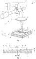
- FIG. 1 illustrated embodiment of a device according to the invention is essentially a conventional laser marking device, which - as will be explained below - has been modified accordingly for use with the inventive method.
- a target 2 for example a steel plate 2 or a steel foil, on which the workpiece W to be marked is placed with the surface O to be marked.
- a laser beam generating device 4 is used with a laser beam source 5, which generates a laser beam L having a wavelength in which the workpiece W to be marked is transmissive.
- the laser beam generating device 4 has, in addition to the laser beam source 5, a beam guiding device 12 in the form of a deflection unit 12 with two deflection mirrors 6, 8 driven by drive motors 7, 9, which are tilted vertically in two for tilting the laser beam L. Take care of directions. Coupled to this beam guiding device 12 or deflecting unit 12 is a focusing device 11, for example a plan field lens or F-theta objective 11 with an F-theta lens. In FIG. 1 the focusing device 11 is shown schematically only by the F-theta lens. The deflection unit 12 may be formed together with this F-theta lens 11 as a unit.
- the F-theta objective 11 deflect the laser beam L, which is deflected at a certain angle by the deflecting mirrors 6, 8, into a plane-parallel plane, which is located in the FIG. 1 shown coordinate system in the x- and y-direction extending plane, which here is preferably located exactly on the target surface 3 to focus.
- a plane-parallel plane which is located in the FIG. 1 shown coordinate system in the x- and y-direction extending plane, which here is preferably located exactly on the target surface 3 to focus.
- another point is hit in this xy plane.
- the focus F of the laser beam L can be moved in any desired manner along a specific marking track given by the marking image B, here for example the word "Panasonic".
- the complete deflection unit 12 with the F-theta objective 11 can also be a commercially available unit, as used in previous laser marking systems.
- the laser beam source 5 and the deflection unit 12 are actuated by the F-theta objective 11 via a control unit 10.
- a commercially available control unit 10 can be used, which must be programmed accordingly, so that the focus F, which is set automatically by the control unit 10 can be set as intended on the target surface 3 or just below the target surface 3.
- the penetration depth t of the metal particles into a glass substrate can be more than 30 ⁇ m at a marking.
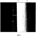
- FIG. 3 shows a micrograph (500x magnification), from which the diffusion channels and the penetration depth can be seen. At one point, the penetration depth t was measured. It is about 48 microns here.
- a FAYb laser with an average power of 12 watts was used. This is a pulsed laser with a laser peak power of up to 20 kW with a 20 ns pulse.
- the pulse repetition time can be set in this system from 10 ⁇ s to 50 ⁇ s.
- the objective was positioned 190 mm from the target surface 3 and the focus F was set directly on the target surface 3. The beam diameter d is then in the focus F about 60 microns (see FIG. 2 ). With this setting in focus, the laser has a power density of approx. 4,000 W / mm 2 .
- metal foils such as aluminum foil
- target materials For example, easy-to-read marks were achieved when using aluminum foil with a laser power of 5 watts, a feed rate of 1,000 mm / s and a pulse repetition time of 50 ⁇ s.
- the use of metal foil is advantageous under certain production conditions, if a specific positioning of the workpiece to be marked on a target surface is too complex and can be applied relatively easily to the workpiece during the production cycle, a metal foil.
Landscapes
- Chemical & Material Sciences (AREA)
- Optics & Photonics (AREA)
- Physics & Mathematics (AREA)
- Engineering & Computer Science (AREA)
- Life Sciences & Earth Sciences (AREA)
- Toxicology (AREA)
- Health & Medical Sciences (AREA)
- Chemical Kinetics & Catalysis (AREA)
- General Chemical & Material Sciences (AREA)
- Geochemistry & Mineralogy (AREA)
- Materials Engineering (AREA)
- Organic Chemistry (AREA)
- Laser Beam Processing (AREA)
- Thermal Transfer Or Thermal Recording In General (AREA)
- Surface Treatment Of Glass (AREA)
Description
Die Erfindung betrifft ein Verfahren zum Einbringen einer Struktur in eine Oberfläche eines in einem bestimmten Wellenlängenbereich transparenten Werkstücks, bei dem die zu strukturierende Oberfläche mit einer ein Targetmaterial enthaltenden Targetoberfläche in Kontakt gebracht wird und mittels eines Laserstrahls, dessen Wellenlänge in dem bestimmten Wellenlängenbereich liegt, durch das Werkstück hindurch zumindest an einer Position derart Energie in den Grenzbereich der zu strukturierenden Oberfläche des Werkstücks und der Targetoberfläche eingebracht wird, dass sich an der betreffenden Position Targetmaterial in der zu strukturierenden Oberfläche ablagert. Darüber hinaus betrifft die Erfindung eine entsprechende Vorrichtung zur Durchführung dieses Verfahrens.The invention relates to a method for introducing a structure into a surface of a workpiece which is transparent in a certain wavelength range, in which the surface to be structured is brought into contact with a target surface containing a target material and by means of a laser beam whose wavelength lies in the specific wavelength range the workpiece is introduced at least at a position such energy in the boundary region of the surface to be structured of the workpiece and the target surface that deposits at the relevant position target material in the surface to be structured. Moreover, the invention relates to a corresponding device for carrying out this method.
Durch Einbringen einer geeigneten Struktur in eine Werkstückoberfläche kann das betreffende Werkstück beispielsweise markiert werden. Hierfür stehen inzwischen handelsübliche Laserbeschriftungs- bzw. Laserkennzeichnungssysteme zur Verfügung, mit denen es möglich ist, als Markierung verschiedene Strukturen, beispielsweise eine Beschriftung, eine maschinenlesbare Kodierung wie z. B. einen Barcode oder ein anderes beliebiges graphisches Element in die Oberfläche des betreffenden Werkstücks einzubringen. Dabei können mit solchen Systemen die verschiedensten Materialien, insbesondere auch transparente Materialien wie Glas oder Plexiglas, markiert werden, sofern geeignete Laser verwendet werden. Normalerweise wird dabei zur Markierung von transparenten Materialien ein Laserstrahl verwendet, dessen Licht möglichst gut von dem transparenten Material absorbiert wird. Beispielsweise hat Glas einen Transmissionsbereich für Lichtwellenlängen zwischen ca. 180 nm und ca. 2.500 nm. Daher werden derzeit zur Glasmarkierung u. a. CO2-Laser mit einer Wellenlänge von 10.600 nm, 9.600 nm oder 9.300 nm verwendet. Die Funktionsweise ist dabei so, dass der Laser an der zu markierenden Stelle in oder auf der Oberfläche des betreffenden Werkstücks fokussiert wird und dadurch an dieser Stelle möglichst viel Energie in das Werkstück eingebracht wird. Dies führt dazu, dass lokal begrenzt an der betreffenden Stelle im Werkstückmaterial sogenannte "Mikrocracks" entstehen, die dann im transparenten Material sichtbar sind. Alternativ kann auch in der Oberfläche eine Gravur eingefügt werden. Dabei wird lokal Material aus der Oberfläche des zu markierenden Werkstücks entfernt.By introducing a suitable structure into a workpiece surface, the relevant workpiece can be marked, for example. For this purpose, commercially available laser marking or laser marking systems are now available, with which it is possible to mark different structures, such as a label, a machine-readable encoding such. B. to introduce a bar code or any other graphical element in the surface of the relevant workpiece. In this case, the most diverse materials, in particular transparent materials such as glass or Plexiglas, can be marked with such systems, provided that suitable lasers are used. Normally, a laser beam is used to mark transparent materials, the light of which is absorbed as well as possible by the transparent material. For example, glass has a transmission range for light wavelengths between about 180 nm and about 2,500 nm. Therefore, currently used for glass marking CO 2 laser having a wavelength of 10,600 nm, 9,600 nm or 9,300 nm. The functioning is in such a way that the laser is focused at the point to be marked in or on the surface of the relevant workpiece and thereby at this point as much energy is introduced into the workpiece. As a result, so-called "microcracks" are formed locally at the relevant point in the workpiece material, which are then visible in the transparent material. Alternatively, an engraving can also be inserted in the surface. In this case, locally material is removed from the surface of the workpiece to be marked.
In der
In der
Um die Sichtbarkeit zu erhöhen, kann eine Gravur beispielsweise mit einem undurchsichtigen Material ausgelegt werden. Die Einbringung dieses Materials in eine Gravur erfordert aber einen zusätzlichen Arbeitsgang. Weitere mögliche Markierungsverfahren sind herkömmliche Druckverfahren, mit denen ein Schriftzug oder ein sonstiges graphisches Element auf die Oberfläche aufgebracht wird. Ein Nachteil dieser Druckverfahren besteht darin, dass die Markierung relativ leicht zerstörbar ist.To increase the visibility, an engraving can be designed, for example, with an opaque material. However, the incorporation of this material in an engraving requires an additional operation. Other possible marking methods are conventional printing methods by which a lettering or other graphic element is applied to the surface. A disadvantage of these printing methods is that the marking is relatively easily destructible.
In der
Außerdem wird in der
In der
Da ein Ansintern von Substratteilchen bei späteren Nachbehandlungen des transparenten Materials nachteilig sein könnte, wird in der
Daneben gibt es noch eine Reihe anderer Verfahren, um Objekte mit Hilfe eines Lasers zu strukturieren. So wird in der
Es ist eine Aufgabe der vorliegenden Erfindung, ein alternatives Verfahren und eine entsprechende Vorrichtung zum Einbringen einer besonders stabilen Struktur in die Oberfläche eines transparenten Werkstücks anzugeben.It is an object of the present invention to provide an alternative method and apparatus for introducing a particularly stable structure into the surface of a transparent workpiece.
Diese Aufgabe wird durch ein Verfahren gemäß Patentanspruch 1 sowie durch eine Vorrichtung gemäß Patentanspruch 14 gelöst.This object is achieved by a method according to
Erfindungsgemäß wird also bei einem Verfahren der eingangs genannten Art ein gepulster Laserstrahl mit einer Pulswiederholrate zwischen 20 kHz und 100 kHz verwendet. Dieser wird so fokussiert, dass sich der Fokus auf oder unter der Targetoberfläche befindet, wobei der Laserstrahl im Fokus eine Leistungsdichte von mehr als 2000 W/mm2 aufweist. Die Leistungsdichte ist dabei die mittlere Laserleistung im Verhältnis zur Fokusfläche.Thus, according to the invention, a pulsed laser beam with a pulse repetition rate between 20 kHz and 100 kHz is used in a method of the type mentioned in the introduction. This is focused so that the focus is on or below the target surface, wherein the laser beam in focus has a power density of more than 2000 W / mm 2 . The power density is the average laser power in relation to the focus area.
Durch die Fokussierung auf die Targetoberfläche oder im Target, beispielsweise knapp unter der Targetoberfläche, wird ein größerer Teil der Energie in das Target eingebracht. Weiterhin wird mit einer erheblich höheren Pulswiederholrate als bei dem genannten Stand der Technik gearbeitet, wobei gleichzeitig eine hohe Leistungsdichte erzeugt wird. Die Pulse sind dabei wegen der hohen Pulswiederholrate entsprechend relativ kurz. Durch die kurzen, aber intensiven Laserpulse gelangen somit die Targetpartikel im Mittel mit einer relativ hohen Energie auf die Oberfläche des transparenten Werkstücks und können somit in diese eindringen. Abweichend von dem oben genannten Stand der Technik wird also hier ganz gezielt versucht, neben dem Aufbringen von Targetmaterial auf die Werkstückoberfläche auch eine möglichst gute Diffusion von Targetmaterial in die Werkstückoberfläche zu erreichen, und das Verfahren gerade nicht so eingestellt, dass sich Targetmaterial möglichst ausschließlich auf der Oberfläche des zu strukturierenden Materials abschlägt.By focusing on the target surface or in the target, for example just below the target surface, a larger part of the energy is introduced into the target. Furthermore, a considerably higher pulse repetition rate than in the mentioned prior art is used, at the same time generating a high power density. The pulses are relatively short because of the high pulse repetition rate. Due to the short but intense laser pulses thus reach the target particles on average with a relatively high energy to the surface of the transparent workpiece and thus can penetrate into this. Notwithstanding the above-mentioned prior art, so here is specifically targeted to achieve not only the application of target material on the workpiece surface and the best possible diffusion of target material in the workpiece surface, and the process just not adjusted so that target material as exclusively as possible the surface of the material to be structured abschlägt.
Bei verschiedenen Experimenten hat sich herausgestellt, dass es mit diesem Verfahren besonders gut möglich ist, Targetmaterial auf und in die Oberfläche des transparenten Werkstücks so einzubringen, dass sich dadurch eine dauerhafte Struktur erzeugen lässt, welche gut sichtbar ist und nur äußerst schwer (z. B. durch ein Abschleifen oder Ausschleifen der Oberfläche) entfernt werden kann.Various experiments have shown that this method makes it particularly well possible to introduce target material onto and into the surface of the transparent workpiece in such a way that a durable structure can be produced which is highly visible and extremely difficult (eg ., By grinding or grinding the surface) can be removed.
Eine geeignete Vorrichtung zum Einbringen einer Struktur in eine Werkstückoberfläche nach dem erfindungsgemäßen Verfahren benötigt neben einer ein Targetmaterial enthaltenden Targetoberfläche, welche beispielsweise an die zu strukturierende Oberfläche des Werkstücks angelegt werden kann oder auf welche das Werkstück aufgelegt wird, eine geeignete Laserstrahlerzeugungseinrichtung zum Erzeugen eines Laserstrahls, dessen Wellenlänge in dem Wellenlängenbereich liegt, in dem das Werkstück transparent ist. Die Laserstrahlerzeugungseinrichtung muss so ausgebildet und angeordnet sein, dass durch ein die Targetoberfläche kontaktierendes Werkstück hindurch mittels des Laserstrahls zumindest an einer Position derart Energie in den Grenzbereich der zu strukturierenden Oberfläche des Werkstücks und der Targetoberfläche einbringbar ist, dass sich an der betreffenden Position Targetmaterial in der zu strukturierenden Oberfläche ablagert. Dabei ist die Laserstrahlerzeugungseinrichtung erfindungsgemäß so ausgebildet, dass sie einen gepulsten Laserstrahl mit einer Pulswiederholrate zwischen 20 kHz und 100 kHz erzeugt und eine Fokussiereinrichtung, z. B. ein geeignetes Objektiv, und eine Steuereinrichtung aufweist, welche den Laserstrahl beim Strukturierungsprozess auf oder knapp unter der Targetoberfläche fokussiert, wobei der Laserstrahl im Fokus eine Leistungsdichte von mehr als 2000 W/mm2 (mittlere Laserleistung im Verhältnis zur Fokusfläche) aufweist.A suitable device for introducing a structure into a workpiece surface according to the method of the invention requires, in addition to a target surface containing a target material, which can be applied, for example, to the surface to be structured of the workpiece or on which the workpiece is placed, a suitable laser beam generating device for generating a laser beam, whose wavelength is in the wavelength range in which the workpiece is transparent. The laser beam generating device must be designed and arranged such that energy can be introduced into the boundary region of the surface of the workpiece to be structured and the target surface by means of the laser beam at least at one position such that target material in the respective position can be introduced at the relevant position deposited to be structured surface. In this case, the laser beam generating device according to the invention is designed so that it generates a pulsed laser beam with a pulse repetition rate between 20 kHz and 100 kHz and a focusing device, for. B. a suitable lens, and a control device which focuses the laser beam in the structuring process on or just below the target surface, wherein the laser beam in focus has a power density of more than 2000 W / mm 2 (average laser power in relation to the focus area).
Hierbei kann die Steuereinrichtung der Vorrichtung bzw. der Laserstrahlerzeugungseinrichtung dazu ausgelegt sein, nicht nur für die gewünschte Einstellung der Fokussierungsparameter, wie Position und Durchmesser des Fokus, zu sorgen, sondern auch für die Einstellung weiterer Laserparameter wie Pulswiederholrate oder Leistung. Diese Steuereinrichtung kann aus einer zentralen Steuereinheit bestehen oder aus mehreren Steuereinheiten, die in geeigneter Weise zur Kommunikation miteinander verbunden sind.In this case, the control device of the device or the laser beam generating device can be designed to provide not only for the desired adjustment of the focusing parameters, such as position and diameter of the focus, but also for the setting of others Laser parameters such as pulse repetition rate or power. This control device may consist of a central control unit or of a plurality of control units, which are suitably connected to each other for communication.
Weitere besonders vorteilhafte Ausgestaltungen und Weiterbildungen der Erfindung ergeben sich aus den abhängigen Ansprüchen sowie der nachfolgenden Beschreibung. Dabei kann die erfindungsgemäße Vorrichtung auch entsprechend den abhängigen Verfahrensansprüchen weitergebildet sein und umgekehrt.Further particularly advantageous embodiments and modifications of the invention will become apparent from the dependent claims and the following description. In this case, the device according to the invention can also be developed according to the dependent method claims and vice versa.
Das Verfahren kann zur Einbringung einer Struktur in Oberflächen verschiedenster transparenter Materialien wie verschiedene Gläser, Plexiglas etc. eingesetzt werden. Besonders bevorzugt eignet es sich zur Einbringung von Strukturen in Oberflächen von Glaswerkstücken, da dies mit anderen Mitteln nur sehr schwer möglich ist und die mit Hilfe des erfindungsgemäßen Verfahrens geschaffenen Strukturen in Glasmaterialien besonders haltbar sind.The method can be used to introduce a structure in surfaces of a variety of transparent materials such as various glasses, Plexiglas, etc. It is particularly preferred for the introduction of structures in surfaces of glass workpieces, since this is very difficult with other means and the structures created by means of the method according to the invention are particularly durable in glass materials.
Auch als Targetmaterialien können verschiedenste Materialien eingesetzt werden. In Experimenten hat sich herausgestellt, dass sich Metalle wie Kupfer, Aluminium, insbesondere Titanal (eine spezielle Aluminiumlegierung), Titan etc. sehr gut eignen. Ganz besonders gut eignen sich Stähle, bevorzugt rostfreie Stähle wie z. B. V2A, bei denen auch mit einer geringeren Laserleistung eine sehr gute optische Erkennbarkeit der Struktur erreicht werden kann.Also as target materials various materials can be used. In experiments, it has been found that metals such as copper, aluminum, in particular titanium (a special aluminum alloy), titanium, etc. are very well suited. Steels are particularly well suited, preferably stainless steels such. B. V2A, where even with a lower laser power a very good visual recognition of the structure can be achieved.
Das Targetmaterial kann besonders bevorzugt auch in Form einer Folie, z. B. als Metallfolie oder metallhaltige bzw. pigmenthaltige Folie, vor dem Strukturierungsprozess auf die Werkstückoberfläche aufgebracht und anschließend wieder entfernt werden. Ganz besonders bevorzugt kann es sich um eine selbsthaftende Folie handeln.The target material may particularly preferably also in the form of a film, for. Example, as a metal foil or metal-containing or pigment-containing film applied before the patterning process on the workpiece surface and then removed again. Most preferably, it may be a self-adhesive film.
Sofern es sich bei dem Targetmaterial um ein leitfähiges Material handelt, können mit diesem Verfahren auch beliebige leitfähige Strukturen auf eine Glasoberfläche bzw. eine Oberfläche eines sonstigen transparenten Materials aufgebracht werden.If the target material is a conductive material, any conductive structures can also be applied to a glass surface or a surface of another transparent material using this method.
Ein bevorzugter Einsatz der Erfindung ist die eingangs erläuterte Markierung von Werkstücken mit Strukturen in Form von Schriftzeichen, Logos usw. Alternativ oder zusätzlich können die auf die erfindungsgemäße Weise eingebrachten Strukturen aber auch völlig anderen Zwecken dienen. Beispielsweise können aus rein optischen Gründen bzw. Designgründen künstlerische Verzierungen, flächige Strukturen, fotografische Abbildungen etc. in die Oberfläche eingebracht werden.A preferred use of the invention is the marking of workpieces having structures in the form of characters, logos, etc. explained at the outset. Alternatively or additionally, however, the structures introduced in the manner according to the invention can also serve completely different purposes. For example, artistic ornamentation, planar structures, photographic images, etc., can be introduced into the surface for purely optical reasons or design reasons.
Ein bevorzugtes weiteres Anwendungsbeispiel ist die Aufbringung von technischen Leiterbahnstrukturen, wie z. B. Antennenstrukturen oder Heizleitern, was insbesondere für Kraftfahrzeugscheiben interessant ist.A preferred further application example is the application of technical trace structures such. As antenna structures or heating conductors, which is particularly interesting for vehicle windows.
Die Wellenlänge des Laserstrahls - d. h. die Wellenlänge des Lichts dieses Laserstrahls - sollte vorzugsweise in einem Bereich von ca. 180 nm bis ca. 2.500 nm, besonders bevorzugt in einem Bereich von ca. 300 nm bis ca. 1.800 nm liegen. Insbesondere bei der Markierung von Glaswerkstücken hat sich der Einsatz eines Lasers mit einer Wellenlänge von ca. 1.060 nm bewährt. Ein Laser mit einer solchen Wellenlänge ist beispielsweise ein sog. FAYb-Laser (Fiber Amplified Ytterbium Laser). Gut einsetzbar sind auch Nd-YAG-Laser (Neodym dotierter Yttrium-Aluminium-Granat-Laser) mit Wellenlängen von 1.064 nm oder 532 nm.The wavelength of the laser beam - d. H. the wavelength of the light of this laser beam - should preferably be in a range of about 180 nm to about 2,500 nm, more preferably in a range of about 300 nm to about 1,800 nm. In particular, when marking glass workpieces, the use of a laser with a wavelength of about 1,060 nm has been proven. A laser with such a wavelength is for example a so-called. FAYb laser (Fiber Amplified Ytterbium Laser). Also suitable are Nd-YAG lasers (neodymium-doped yttrium-aluminum-garnet laser) with wavelengths of 1,064 nm or 532 nm.
Weiterhin weist die Laserstrahlerzeugungseinrichtung bevorzugt eine Strahlführungseinrichtung auf, um den Laserfokus entlang einer gemäß einem Strukturierungsbild vorgegebenen Strukturierungsspur zu bewegen. Das heißt, der Laser wird punktuell entlang dieser Strukturierungsspur, beispielsweise entlang eines Schriftzugs, mit einer vorgegebenen Vorschubgeschwindigkeit schrittweise oder kontinuierlich verfahren, um so das gewünschte Strukturierungsbild zu erzeugen.Furthermore, the laser beam generating device preferably has a beam guiding device in order to move the laser focus along a structuring track predetermined according to a structuring image. That is, the laser is selectively along this Strukturierungsspur, for example along a font, with a predetermined Feed rate stepwise or continuously, so as to produce the desired structuring image.
Vorzugsweise erfolgt der Vorschub mit einer Vorschubgeschwindigkeit von mehr als 70 mm/s, besonders bevorzugt von mehr als 100 mm/s, je nach konkreter Anwendung gegebenenfalls sogar noch erheblich höher.Preferably, the feed takes place at a feed rate of more than 70 mm / s, more preferably of more than 100 mm / s, depending on the specific application, if necessary, even considerably higher.
Eine solche Strahlführungseinrichtung kann auf beliebige Weise aufgebaut sein. Beispielsweise kann der Laser über einen Lichtleiter geführt werden und dieser Lichtleiter wird durch geeignete Stelleinrichtungen passend justiert. Die Strahlführungseinrichtung kann aber ebenso in üblicher Weise mit Ablenkeinheiten aufgebaut sein, beispielsweise mit zwei Umlenkspiegeln, Prismen oder dergleichen. Um mit einem solchen System dafür zu sorgen, dass der Fokus des Laserstrahls jeweils in einer Ebene direkt auf oder unter der Targetoberfläche bleibt, muss die Fokussiereinrichtung entsprechend ausgestaltet sein. Hierzu bietet es sich z. B. an, ein Planfeld-Objektiv mit einer F-Theta-Linse oder Ähnliches einzusetzen. Ein solches F-Theta-Objektiv fokussiert den Laserstrahl auf eine plane Bildfeldebene. Dabei besteht eine exakte Proportionalität zwischen dem Einfallswinkel des Strahls und der Position des fokussierten Bildpunkts im Bildfeld, d. h. in der Ebene, in der die Strukturierung erfolgen soll. Ebenso können auch geeignete 3D-Objektive eingesetzt werden, z. B. wenn die zu strukturierende Oberfläche gekrümmt ist. Geeignete Ablenkeinheiten mit integrierten Fokussierobjektiven sind beispielsweise für die Verwendung in üblichen Laserbeschriftungs- bzw. Laserkennzeichnungsvorrichtungen im Handel erwerbbar. Diese können auch für die erfindungsgemäße Vorrichtung verwendet werden. Ebenso können auch die für diese Einrichtungen vorgesehenen Steuerungen verwendet werden. Erforderlich ist jedoch, dass ein geeigneter Laser verwendet wird, welcher eine Wellenlänge aufweist, in der das zu strukturierende Material transmissiv ist, und dass die Steuerung derart eingestellt, ggf. auch für eine automatische Steuerung entsprechend programmiert ist, dass der Fokus sich nicht in dem zu strukturierenden Werkstück selbst, sondern z. B. auf oder knapp unter der Targetoberfläche befindet.Such a beam guiding device can be constructed in any desired way. For example, the laser can be guided over an optical waveguide and this optical waveguide is suitably adjusted by suitable adjusting devices. However, the beam guiding device can also be constructed in the usual way with deflection units, for example with two deflecting mirrors, prisms or the like. In order to ensure with such a system that the focus of the laser beam in each case remains in a plane directly on or below the target surface, the focusing must be designed accordingly. For this it offers z. Example, to use a plano lens with an F-theta lens or the like. Such an F-theta lens focuses the laser beam on a flat image field plane. There is an exact proportionality between the angle of incidence of the beam and the position of the focused pixel in the image field, ie in the plane in which the structuring is to take place. Likewise, suitable 3D lenses can be used, for. B. when the surface to be structured is curved. Suitable deflection units with integrated focusing lenses are commercially available, for example, for use in conventional laser marking or laser marking devices. These can also be used for the device according to the invention. Likewise, the controls provided for these devices can also be used. It is necessary, however, that a suitable laser is used, which has a wavelength in which the material to be structured is transmissive, and that the control is set in such a way, if appropriate also programmed for automatic control, that the focus not in the workpiece to be structured itself, but z. B. is located on or just below the target surface.
Wie bereits eingangs erläutert, wird erfindungsgemäß der Strukturierungsprozess bewusst so ausgelegt, dass Partikel des Targetmaterials möglichst gut in die zu strukturierende Oberfläche des transparenten Werkstücks hinein diffundieren. Bevorzugt erfolgt daher die Strukturierung so, dass Partikel des Targetmaterials zumindest an einer Stelle mit der größten Eindringtiefe - z. B. bei einer Punktmarkierung im Mittelpunkt der Punktmarkierung oder einer Linienmarkierung entlang einer Mittellinie der Linienmarkierung - mindestens ca. 15 µm, vorzugsweise mindestens ca. 30 µm tief in die zu strukturierende Oberfläche eindringen. In den bisher durchgeführten Testmarkierungen hat sich gezeigt, dass mit dem erfindungsgemäßen Verfahren ohne weiteres eine Eindringtiefe der Targetpartikel in die Werkstückoberfläche von bis zu 30 µm und mehr erreichbar ist.As already explained at the outset, according to the invention, the structuring process is deliberately designed so that particles of the target material diffuse as well as possible into the surface to be structured of the transparent workpiece. Preferably, therefore, the structuring is carried out so that particles of the target material at least at one point with the greatest penetration depth - z. B. at a point mark in the center of the dot marking or a line marking along a center line of the line marking - penetrate at least about 15 microns, preferably at least about 30 microns deep in the surface to be structured. In the test markings carried out so far, it has been found that with the method according to the invention, a penetration depth of the target particles into the workpiece surface of up to 30 μm and more can be achieved without difficulty.
Vorzugsweise sollte dazu möglichst kurzzeitig eine hohe Energie im Target eingebracht werden. Dabei wird der Laserstrahl bevorzugt so gesteuert, dass die Temperatur in der zu strukturierenden Oberfläche auch während der Strukturierung unterhalb der Schmelztemperatur des Werkstückmaterials liegt, und zwar auch im unmittelbaren Grenzbereich zur Targetoberfläche, in der sich gerade der Laserstrahlfokus befindet. D. h. die Werkstückoberfläche soll nicht lokal angeschmolzen werden. Bei Glas liegt die Schmelztemperatur je nach Glastyp zwischen ca. 1.000 °C und ca. 1.600°C.Preferably, as long as possible a high energy should be introduced in the target. In this case, the laser beam is preferably controlled so that the temperature in the surface to be structured is also below the melting temperature of the workpiece material during patterning, and indeed also in the immediate boundary region to the target surface in which the laser beam focus is currently located. Ie. The workpiece surface should not be melted locally. Depending on the glass type, the melting point of glass is between approx. 1,000 ° C and approx. 1,600 ° C.
Andererseits sollte die Temperatur in der gerade zu markierenden Werkstückoberfläche auch nicht zu gering sein, da eine höhere Temperatur die Diffusion begünstigt. Besonders bevorzugt ist eine Temperatur oberhalb von ca. 600°C.On the other hand, the temperature should not be too low in the currently to be marked workpiece surface, as a higher temperature favors the diffusion. Particularly preferred is a temperature above about 600 ° C.
Die Einstellung der optimalen Bedingungen erfolgt durch die Justage verschiedener Parameter, die zum einen die vom Laserstrahl in das Target eingebrachte Energie und zum anderen die Zeit determinieren, in der diese Energie eingebracht wird.The optimum conditions are set by adjusting various parameters, which determine the energy introduced by the laser beam into the target and the time at which this energy is introduced.
Es hat sich als vorteilhaft herausgestellt, wenn der Laserstrahl im Fokus eine möglichst hohe Leistungsdichte aufweist. Daher wird der Laserstrahl vorzugsweise so eingestellt, dass er im Fokus eine Leistungsdichte von mehr als ca. 3 kW/mm2 aufweist, besonders bevorzugt mehr als ca. 10 kW/mm2, ganz besonders bevorzugt sogar mehr als ca. 100 kW/mm2.It has proven to be advantageous if the laser beam in focus has the highest possible power density. Therefore, the laser beam is preferably adjusted so that it has a power density of more than about 3 kW / mm 2 in the focus, more preferably more than about 10 kW / mm 2 , most preferably even more than about 100 kW / mm 2 .
Hierzu muss zum einen der Fokusdurchmesser ausreichend gering sein. Vorzugsweise wird ein Fokusdurchmesser eingestellt, der kleiner als 60 µm, besonders bevorzugt kleiner als 40 µm, ist. In Tests wurden beispielsweise hervorragende Markierungen mit einem Fokusdurchmesser von nur ca. 30 µm erzielt.For this purpose, on the one hand, the focus diameter must be sufficiently low. Preferably, a focus diameter is set which is smaller than 60 .mu.m, more preferably smaller than 40 .mu.m. In tests, for example, excellent markings with a focus diameter of only about 30 μm were achieved.
Zum anderen muss die mittlere Leistung des Lasers ausreichend hoch sein. Vorzugsweise sollte diese höher als 10 W sein. Bevorzugt wird ein Laser eingesetzt, dessen mittlere Leistung zwischen 10 W und 50 W einstellbar ist. Bei einem Fokusdurchmesser von ca. 60 µm reicht eine Leistung von 12 W aus, um im Fokus eine Leistungsdichte von mehr als 4 kW/mm2 zu erreichen.On the other hand, the average power of the laser must be sufficiently high. Preferably, this should be higher than 10W. Preferably, a laser is used, the average power between 10 W and 50 W is adjustable. With a focus diameter of approx. 60 μm, a power of 12 W is sufficient to achieve a power density of more than 4 kW / mm 2 in the focus.
Neben der eingebrachten Leistung spielen aber für das Temperaturverhalten im Target - und somit auch in der angrenzenden Werkstückoberfläche - auch die bereits oben definierte Vorschubgeschwindigkeit sowie die Pulswiederholrate des Laserstrahls eine Rolle. Wie gesagt, wird erfindungsgemäß mit einer relativ hohen Pulswiederholrate zwischen 20 kHz und 100 kHz gearbeitet. Dies entspricht einer Pulswiederholzeit zwischen 10 µs und 50 µs.In addition to the power introduced, however, the feed rate already defined above and the pulse repetition rate of the laser beam also play a role in the temperature behavior in the target, and thus also in the adjacent workpiece surface. As mentioned, the invention operates with a relatively high pulse repetition rate between 20 kHz and 100 kHz. This corresponds to a pulse repetition time between 10 μs and 50 μs.
Entsprechend dieser kurzen Pulswiederholzeit müssen auch die Laserpulse selbst relativ kurz sein. Die Pulsdauer der Laserpulse ist vorzugsweise kürzer als 100 ns, besonders bevorzugt kürzer als 20 ns. Da eine möglichst kurze Pulsdauer vorteilhaft ist, wäre eine Pulsdauer im ps-Bereich oder darunter ganz besonders bevorzugt.In accordance with this short pulse repetition time, the laser pulses themselves must also be relatively short. The pulse duration of the laser pulses is preferably shorter than 100 ns, particularly preferably shorter than 20 ns. Since the shortest possible pulse duration is advantageous, a pulse duration in the ps range or below would be particularly preferred.
Die kurzen Pulsdauern führen bei einer gegebenen mittleren Leistung zu einer entsprechend hohen Laserpulsspitzenleistung (auch "Laser Peak Power" genannt). Bei dem erfindungsgemäßen Verfahren wird vorzugsweise mit Laserpulsspitzenleistung größer als 10 kW, besonders bevorzugt größer als 25 kW, gearbeitet. Es wird folglich dafür gesorgt, dass möglichst viel Energie in möglichst kurzer Zeit in das Targetmaterial eingebracht wird, um so einerseits die Partikel des Targetmaterials mit ausreichender Energie auszustatten und andererseits die Temperatur im zu markierenden Werkstück auch lokal in den gewünschten Temperaturgrenzen zu halten und so eine möglichst gute Diffusion von Targetpartikeln in die Werkstückoberfläche zu erreichen.For a given average power, the short pulse durations result in a correspondingly high laser pulse peak power (also called "laser peak power"). In the method according to the invention is preferably carried out with laser pulse peak power greater than 10 kW, more preferably greater than 25 kW. It is therefore ensured that as much energy as possible is introduced into the target material in the shortest possible time so as to equip the particles of the target material with sufficient energy and also to keep the temperature in the workpiece to be marked locally in the desired temperature limits and so on To achieve the best possible diffusion of target particles into the workpiece surface.
Die Erfindung wird im Folgenden unter Hinweis auf die beigefügten Figuren anhand eines Ausführungsbeispiels noch einmal näher erläutert. Hieraus ergeben sich noch weitere Einzelheiten und Vorteile der Erfindung. Es zeigen:
Figur 1- eine schematische Darstellung eines Ausführungsbeispiels einer erfindungsgemäßen Vorrichtung bei der Markierung eines Glaswerkstücks,
Figur 2- einen Schnitt durch das Glaswerkstück mit dem darunter befindlichen Target beim Einbringen der Markierung,
Figur 3- einen Schliff durch ein mit dem erfindungemäßen Verfahren markiertes Glaswerkstück im Bereich der Markierung, zur Bestimmung der Eindringtiefe der Targetpartikel.
- FIG. 1
- a schematic representation of an embodiment of a device according to the invention in the marking of a glass workpiece,
- FIG. 2
- a section through the glass workpiece with the underlying target during insertion of the mark,
- FIG. 3
- a grinding through a marked with the erfindungemäßen method glass workpiece in the region of the marking, for determining the penetration depth of the target particles.
Im Folgenden wird - ohne die Erfindung auf diesen Einsatz zu beschränken - davon ausgegangen, dass das Einbringen der Struktur in die Oberfläche zur Markierung des Werkstücks dient. Wie erwähnt können mit dem erfindungsgemäßen Verfahren genauso auch Strukturen für andere Zwecke wie z. B. technische Leiterbahnstrukturen oder graphische Flächen in die Oberfläche eingebracht werden.In the following, it is assumed, without limiting the invention to this use, that the introduction of the structure into the surface serves to mark the workpiece. As mentioned, structures for other purposes such as. B. technical trace structures or graphic surfaces are introduced into the surface.
Bei dem in
Ein wesentlicher Punkt ist hierbei, dass sich unterhalb des zu markierenden Werkstücks W ein Target 2, beispielsweise eine Stahlplatte 2 oder eine Stahlfolie, befindet, auf welche das zu markierende Werkstück W mit der zu markierenden Oberfläche O aufgelegt wird. Die Oberfläche der Stahlplatte 2 oder Stahlfolie, auf der die zu markierende Oberfläche O des Werkstücks möglichst großflächig innerhalb des Bereichs aufliegt, in dem die Markierung M anzubringen ist, bildet die Targetoberfläche 3.An essential point here is that below the workpiece W to be marked is a
Weiterhin wird eine Laserstrahlerzeugungseinrichtung 4 mit einer Laserstrahlquelle 5 verwendet, welche einen Laserstrahl L mit einer Wellenlänge erzeugt, in dem das zu markierende Werkstück W transmissiv ist. Der Transmissionsbereich von Glas liegt zwischen 180 nm und 2.500 nm. Daher wird vorzugsweise hier ein FAYb-Laser mit einer Wellenlänge von λ = 1.060 nm eingesetzt.Furthermore, a laser
Die Laserstrahlerzeugungseinrichtung 4 weist neben der Laserstrahlquelle 5 eine Strahlführungseinrichtung 12 in Form einer Ablenkeinheit 12 mit zwei über Ansteuermotoren 7, 9 angetriebenen Ablenkspiegeln 6, 8 auf, welche für eine Verkippung des Laserstrahls L in zwei senkrechte Richtungen sorgen. Angekoppelt an diese Strahlführungseinrichtung 12 bzw. Ablenkeinheit 12 ist eine Fokussierungseinrichtung 11, beispielsweise ein Planfeld-Objektiv bzw. F-Theta-Objektiv 11 mit einer F-Theta-Linse. In
Die komplette Ablenkeinheit 12 mit dem F-Theta-Objektiv 11 kann auch eine handelsübliche Einheit sein, wie sie bei bisherigen Laserbeschriftungssystemen eingesetzt wird. Angesteuert werden die Laserstrahlquelle 5 und die Ablenkeinheit 12 mit dem F-Theta-Objektiv 11 über eine Steuereinheit 10. Auch hierbei kann eine handelsübliche Steuereinheit 10 verwendet werden, welche entsprechend programmiert werden muss, damit der Fokus F, welcher von der Steuereinheit 10 automatisch eingestellt werden kann, wie vorgesehen auf die Targetoberfläche 3 oder knapp unterhalb der Targetoberfläche 3 eingestellt wird.The
Es wird so lokal in dem Bereich, in dem sich der Laserstrahl L aktuell befindet, bzw. auch um diesen Bereich herum, Energie in den Grenzbereich G der zu strukturierenden Oberfläche O des Werkstücks W und der Targetoberfläche 3, d. h. sowohl in das Target als auch in die Werkstückoberfläche O, eingebracht, wobei der größte Teil der Energie zunächst im Fokus F auf der Targetoberfläche 3 eingebracht wird. Dadurch wird das Metall so stark erhitzt, dass Metallpartikel sich auf der Glasoberfläche O niederschlagen und auch in diese eindringen. Dies ist schematisch in
Versuche haben gezeigt, dass an einer Markierung die Eindringtiefe t der Metallpartikel in ein Glassubstrat mehr als 30 µm betragen kann.
Für diese Versuche wurde ein FAYb-Laser mit einer durchschnittlichen Leistung von 12 Watt verwendet. Hierbei handelt es sich um einen gepulsten Laser mit einer Laserspitzenleistung von bis zu 20 kW bei einem 20 ns langen Puls. Die Pulswiederholzeit kann bei diesem System von 10 µs bis 50 µs eingestellt werden. Der Laser ist ein sogenannter "Single Mode Laser" (Mode TEM00) und hat einen Güteparameter M2 = 1,4. Bei den Tests wurde das Objektiv 190 mm von der Targetoberfläche 3 positioniert und der Fokus F direkt auf die Targetoberfläche 3 eingestellt. Der Strahldurchmesser d beträgt im Fokus F dann ca. 60 µm (siehe
Insbesondere mit verschiedenen Metallen wurden Versuche durchgeführt, die zu besonders gut lesbaren Markierungen geführt haben. So wurden zum einen Versuche mit Kupfer und mit Titanal als Targetmaterial durchgeführt, wobei die Laserleistung jeweils 10 Watt, die Vorschubgeschwindigkeit jeweils 70 mm/s und die Pulswiederholzeit jeweils 50 µs betrug. Die Markierung M war bei diesen Bedingungen bei beiden Targetmaterialien gut lesbar. Bei einem weiteren Versuch wurde als Targetmaterial Aluminium verwendet. Bei einer Laserleistung von 10 Watt und einer Vorschubgeschwindigkeit von 80 mm/s sowie einer Pulswiederholzeit von 50 µs wurde auch hier eine recht gut lesbare Markierung erzeugt.In particular, with different metals experiments have been carried out, which have led to particularly legible markers. For example, tests were carried out with copper and Titanal as the target material, with the laser power in each
Dabei hat sich herausgestellt, dass grundsätzlich auch Metallfolien, beispielsweise Alufolie, als Targetmaterialien geeignet sind. So wurden gut lesbare Markierungen bei einer Verwendung von Alufolie mit einer Laserleistung von 5 Watt, einer Vorschubgeschwindigkeit von 1.000 mm/s und einer Pulswiederholzeit von 50 µs erzielt. Die Verwendung von Metallfolie ist unter bestimmten Produktionsbedingungen vorteilhaft, wenn eine spezielle Positionierung des zu markierenden Werkstücks auf einer Targetoberfläche zu aufwändig ist und sich innerhalb des Produktionsgangs eine Metallfolie relativ einfach auf das Werkstück aufbringen lässt.It has been found that in principle also metal foils, such as aluminum foil, are suitable as target materials. For example, easy-to-read marks were achieved when using aluminum foil with a laser power of 5 watts, a feed rate of 1,000 mm / s and a pulse repetition time of 50 μs. The use of metal foil is advantageous under certain production conditions, if a specific positioning of the workpiece to be marked on a target surface is too complex and can be applied relatively easily to the workpiece during the production cycle, a metal foil.
Die besten Ergebnisse wurden mit Stahl erreicht. Dabei wurden mit einer Leistung von nur 8 Watt und einer Vorschubgeschwindigkeit von 150 mm/s bei einer Pulswiederholzeit von 50 µs besonders gut lesbare Markierungen erzeugt.The best results were achieved with steel. With a power of only 8 watts and a feed rate of 150 mm / s with a pulse repetition time of 50 μs, particularly legible markings were generated.
Die so markierten Werkstücke wurden dann hinsichtlich einer Zerstörbarkeit der Markierungen getestet. Dabei hat sich herausgestellt, dass sich die Markierungen weder durch Reinigungs- bzw. Scheuermittel noch durch Abkratzen mit einer Klinge oder Ähnlichem erheblich beschädigen ließen.The thus marked workpieces were then tested for destructibility of the markings. It has been found that the markings could be damaged neither by cleaning or abrasives nor by scraping with a blade or the like.
Mit dem erfindungsgemäßen Verfahren lassen sich also auf einfache Weise sehr gut haltbare Strukturen für beliebige Funktionen insbesondere in Glasoberflächen erzeugen, wobei vorteilhafterweise relativ einfach modifizierte herkömmliche Laserbeschriftungssysteme nutzbar sind.With the method according to the invention, it is thus possible in a simple manner to produce very durable structures for any desired functions, in particular in glass surfaces, advantageously allowing relatively simple modification of conventional laser marking systems.
Es wird abschließend noch einmal darauf hingewiesen, dass es sich bei den in den Figuren dargestellten Vorrichtungen sowie den im Zusammenhang damit erläuterten konkreten Verfahren lediglich um Ausführungsbeispiele handelt, welche vom Fachmann in vielfacher Hinsicht variiert werden können, ohne den Rahmen der Erfindung zu verlassen. Es wird außerdem der Vollständigkeit halber darauf hingewiesen, dass die Verwendung der unbestimmten Artikel "ein" bzw. "eine" nicht ausschließt, dass die betreffenden Merkmale auch mehrfach vorhanden sein können.It is finally pointed out once again that the devices illustrated in the figures and the concrete method explained in connection therewith are merely exemplary embodiments which can be varied by the person skilled in the art in many respects without departing from the scope of the invention. It is also noted for the sake of completeness that the use of the indefinite article "a" or "an" does not preclude that the characteristics in question may also be present more than once.
Claims (14)
- A method for incorporating a structure (M) into a surface (O) of a workpiece (W) which is transparent at a specific wavelength range, in which the surface (O) to be structured is brought in contact with a target surface (3) containing a target material and by means of a laser beam (2), the wavelength of which lies in the specific wavelength range, energy is introduced through the workpiece (W) at least at one position into the boundary region (G) of the surface (O), to be structured, of the workpiece (W) and of the target surface (3) such that at the relevant position target material is deposited in the surface (O) to be structured,
characterized in that
a pulsed laser beam (L) with a pulse repetition rate between 20 kHz and 100 kHz is used, which is focussed so that the focus is situated on or under the target surface, wherein the laser beam in the focus has a power density (mean laser power in relation to the focus area) of more than 2000 W/mm2. - The method according to Claim 1, characterized in that the workpiece (W) is made of glass.
- The method according to Claim 1 or 2, characterized in that the target material is a metal.
- The method according to Claim 3, characterized in that the target material is a steel.
- The method according to one of the preceding claims, characterized in that the structure (M) is designed for marking the workpiece (W).
- The method according to one of the preceding claims, characterized in that the focus (F) of the laser beam (L) is moved along a structuring track, specified according to a structuring image (B), at an advancing rate of more than 70 mm/s, particularly preferably of more than 100 mm/s.
- The method according to one of the preceding claims, characterized in that the structuring is carried out such that particles of the target material penetrate the surface to be structured at least at one point to a depth of at least about 15 µm, preferably at least about 30 µm.
- The method according to one of the preceding claims, characterized in that the laser beam is controlled such that the temperature in the surface to be structured during the structuring lies below the melting temperature of the workpiece material.
- The method according to one of the preceding claims, characterized in that the laser beam in the focus has a power density of more than about 3 kW/mm2, preferably more than about 10 kW/mm2, particularly preferably more than about 100 kW/mm2.
- The method according to one of the preceding claims, characterized in that the focus diameter is less than 60 µm, preferably less than 40 µm.
- The method according to one of the preceding claims, characterized in that the pulse duration of the laser pulses is less than 100 ns, preferably less than 20 ns.
- The method according to one of the preceding claims, characterized in that the laser pulse peak power is more than 10 kW, preferably more than 25 kW.
- An apparatus (1) for incorporating a structure (M) into a surfce (O) of a workpiece (W) which is transparent in a specific wavelength range, comprising- a target surface (3), containing a target material, for contacting the surface (O), to be structured, of the workpiece (W),- a laser beam generation device (4) for generating a laser beam (L), the wavelength of which lies in the specific wavelength range, wherein the laser beam generation device (4) is designed and arranged such that energy can be introduced into the boundary region (G) of the surface (O), to be structured, of the workpiece (W) and of the target surface (3), at least at one position, by means of the laser beam (L) through a workpiece (W) contacting the target surface (3), such that at the relevant position target material is deposited in the surface (O) to be structured,characterized in that the laser beam generation device (4) is designed such that it generates a pulsed laser beam (L) with a pulse repetition rate between 20 kHz and 100 kHz, and has a focussing device (11) and a control device (10) which focusses the laser beam (L) during the structuring process onto or just under the target surface (3), wherein the laser beam in the focus has a power density (mean laser power in relation to the focus area) of more than 2000 W/mm2.
- The device according to Claim 13, characterized in that the laser beam generation device (4) has a beam guidance device (12) in order to move the laser focus (F) along a structuring track defined according to a structuring image (B).
Applications Claiming Priority (2)
| Application Number | Priority Date | Filing Date | Title |
|---|---|---|---|
| DE102007018402A DE102007018402A1 (en) | 2007-04-17 | 2007-04-17 | Method for introducing a structure into a surface of a transparent workpiece |
| PCT/EP2008/002840 WO2008125273A1 (en) | 2007-04-17 | 2008-04-10 | Method for incorporating a structure into a surface of a transparent workpiece |
Publications (2)
| Publication Number | Publication Date |
|---|---|
| EP2144728A1 EP2144728A1 (en) | 2010-01-20 |
| EP2144728B1 true EP2144728B1 (en) | 2017-01-04 |
Family
ID=39535712
Family Applications (1)
| Application Number | Title | Priority Date | Filing Date |
|---|---|---|---|
| EP08735149.0A Not-in-force EP2144728B1 (en) | 2007-04-17 | 2008-04-10 | Method for incorporating a structure into a surface of a transparent workpiece |
Country Status (6)
| Country | Link |
|---|---|
| US (1) | US8399798B2 (en) |
| EP (1) | EP2144728B1 (en) |
| JP (1) | JP5465170B2 (en) |
| CN (1) | CN101678502B (en) |
| DE (1) | DE102007018402A1 (en) |
| WO (1) | WO2008125273A1 (en) |
Cited By (1)
| Publication number | Priority date | Publication date | Assignee | Title |
|---|---|---|---|---|
| CN111230320A (en) * | 2020-03-16 | 2020-06-05 | 深圳泰德激光科技有限公司 | Laser marking method for surface of anodic aluminum oxide |
Families Citing this family (22)
| Publication number | Priority date | Publication date | Assignee | Title |
|---|---|---|---|---|
| DE102007018402A1 (en) * | 2007-04-17 | 2008-10-23 | Panasonic Electric Works Europe Ag | Method for introducing a structure into a surface of a transparent workpiece |
| DE102007028042B3 (en) * | 2007-06-14 | 2008-08-07 | Universität Zu Lübeck | Using laser to make bubbles or cavities in transparent materials by focused, non-linear pulse absorption, operates at specified wavelength and pulse duration with controlled, uniform intensity |
| DE102008058535A1 (en) * | 2008-11-21 | 2010-05-27 | Tesa Se | Process for material processing with high-energy radiation |
| JP6046329B2 (en) * | 2010-01-08 | 2016-12-14 | 早川ゴム株式会社 | Joining method using laser light |
| EP2563600B2 (en) * | 2010-04-30 | 2018-07-25 | Becton Dickinson France | Method for marking a transparent container |
| RU2614502C2 (en) * | 2011-09-23 | 2017-03-28 | Бёльи-Гравюр Са | Method and device for contoured surface formation on steel embossing shaft |
| KR20140079844A (en) * | 2011-11-17 | 2014-06-27 | 쌩-고벵 글래스 프랑스 | Laser-marked polymer workpiece |
| CN103253197B (en) * | 2012-10-08 | 2016-08-31 | 上海博迩森汽车配件有限公司 | Rear-view mirror slice processing method |
| DE102012219249A1 (en) * | 2012-10-22 | 2014-02-13 | Bundesdruckerei Gmbh | Device for laser personalization of security elements |
| JPWO2014080822A1 (en) | 2012-11-20 | 2017-01-05 | 国立大学法人九州大学 | Laser processing apparatus and laser processing method |
| EP3047932B1 (en) * | 2015-01-21 | 2018-12-26 | Agie Charmilles New Technologies SA | Method of laser ablation for engraving of a surface with patch optimization, with corresponding software and machine tool |
| CA2931245C (en) | 2015-05-26 | 2023-07-25 | National Research Council Of Canada | Metallic surface with karstified relief, forming same, and high surface area metallic electrochemical interface |
| GB201603991D0 (en) * | 2016-03-08 | 2016-04-20 | Univ Dundee | Processing method and apparatus |
| DE102016203363A1 (en) * | 2016-03-02 | 2017-09-07 | Bayerische Motoren Werke Aktiengesellschaft | Method for integrally joining an aluminum cast component with a joining partner and component |
| CN105710538A (en) * | 2016-04-22 | 2016-06-29 | 中国电子科技集团公司第十三研究所 | Manufacturing method for glass wafer laser mark |
| GB201609086D0 (en) * | 2016-05-20 | 2016-07-06 | Spi Lasers Uk Ltd | Method for creating a mark with a desired colour on an article |
| DE102016122113A1 (en) * | 2016-11-17 | 2018-05-17 | Karlsruher Institut für Technologie | Device for identifying objects and living beings in water, as well as methods for producing and using the device and their use |
| CN106335289A (en) * | 2016-11-18 | 2017-01-18 | 深圳英诺激光科技有限公司 | Equipment and method for carrying out white or color marking on transparent material |
| US10710200B2 (en) * | 2017-05-23 | 2020-07-14 | Sakai Display Products Corporation | Method for producing device support base and laser cleaning apparatus |
| WO2018233842A1 (en) * | 2017-06-23 | 2018-12-27 | Hp Indigo B.V. | Method, apparatus and system for material displacement by a pulsed laser beam |
| CN114502316B (en) * | 2021-02-26 | 2022-12-27 | 国立大学法人名古屋工业大学 | Laser processing device, thickness detection method and thickness detection device |
| CN114083156A (en) * | 2021-12-31 | 2022-02-25 | 杭州银湖激光科技有限公司 | Laser processing method of transparent material |
Citations (5)
| Publication number | Priority date | Publication date | Assignee | Title |
|---|---|---|---|---|
| DE19517625A1 (en) * | 1995-05-13 | 1996-11-14 | Budenheim Rud A Oetker Chemie | Laser printing esp. on glass or plastic substrate |
| DE19637255C1 (en) * | 1996-09-13 | 1997-12-11 | Jenoptik Jena Gmbh | Indirect laser marking of transparent material e.g. glass |
| US5987920A (en) * | 1996-09-19 | 1999-11-23 | U.S. Philips Corporation | Method of producing a patterned surfacial marking on a transparent body |
| DE102006029941A1 (en) * | 2006-06-29 | 2008-01-03 | Calyxo Gmbh | Procedure for indirect inscription of glass by passing focused laser beam of appropriate wave length through the glass on absorbing substrate such as metal/semi-metal and bringing the substrate to the upper surface of the glass |
| DE102007018402A1 (en) * | 2007-04-17 | 2008-10-23 | Panasonic Electric Works Europe Ag | Method for introducing a structure into a surface of a transparent workpiece |
Family Cites Families (11)
| Publication number | Priority date | Publication date | Assignee | Title |
|---|---|---|---|---|
| FI103396B1 (en) * | 1994-03-24 | 1999-06-30 | Laserplus Oy | Method and apparatus for making marks on a glass surface |
| JP3616679B2 (en) | 1995-09-07 | 2005-02-02 | カルソニックカンセイ株式会社 | End closure pipe and heat exchanger header |
| US5761111A (en) | 1996-03-15 | 1998-06-02 | President And Fellows Of Harvard College | Method and apparatus providing 2-D/3-D optical information storage and retrieval in transparent materials |
| DE69704698T2 (en) * | 1996-12-27 | 2002-01-31 | Omron Tateisi Electronics Co | Method of labeling an object that uses a laser beam |
| US6281471B1 (en) * | 1999-12-28 | 2001-08-28 | Gsi Lumonics, Inc. | Energy-efficient, laser-based method and system for processing target material |
| US6929886B2 (en) | 2001-01-02 | 2005-08-16 | U-C-Laser Ltd. | Method and apparatus for the manufacturing of reticles |
| JP4246645B2 (en) | 2003-01-28 | 2009-04-02 | 有限会社岩倉溶接工業所 | Laser color marking method |
| US20060213886A1 (en) * | 2003-03-13 | 2006-09-28 | Sanders Renatus H M | Marking method and market object |
| JP2004351746A (en) * | 2003-05-29 | 2004-12-16 | Central Glass Co Ltd | Method for drawing picture on glass by laser scan |
| CN1603888A (en) | 2004-11-05 | 2005-04-06 | 中国科学院上海光学精密机械研究所 | Method for transmission of periodic microstructure by femtosecond laser coherence technique |
| US7626138B2 (en) | 2005-09-08 | 2009-12-01 | Imra America, Inc. | Transparent material processing with an ultrashort pulse laser |
-
2007
- 2007-04-17 DE DE102007018402A patent/DE102007018402A1/en not_active Withdrawn
-
2008
- 2008-04-10 WO PCT/EP2008/002840 patent/WO2008125273A1/en active Application Filing
- 2008-04-10 CN CN2008800171775A patent/CN101678502B/en not_active Expired - Fee Related
- 2008-04-10 JP JP2010503386A patent/JP5465170B2/en active Active
- 2008-04-10 EP EP08735149.0A patent/EP2144728B1/en not_active Not-in-force
- 2008-04-10 US US12/596,521 patent/US8399798B2/en not_active Expired - Fee Related
Patent Citations (5)
| Publication number | Priority date | Publication date | Assignee | Title |
|---|---|---|---|---|
| DE19517625A1 (en) * | 1995-05-13 | 1996-11-14 | Budenheim Rud A Oetker Chemie | Laser printing esp. on glass or plastic substrate |
| DE19637255C1 (en) * | 1996-09-13 | 1997-12-11 | Jenoptik Jena Gmbh | Indirect laser marking of transparent material e.g. glass |
| US5987920A (en) * | 1996-09-19 | 1999-11-23 | U.S. Philips Corporation | Method of producing a patterned surfacial marking on a transparent body |
| DE102006029941A1 (en) * | 2006-06-29 | 2008-01-03 | Calyxo Gmbh | Procedure for indirect inscription of glass by passing focused laser beam of appropriate wave length through the glass on absorbing substrate such as metal/semi-metal and bringing the substrate to the upper surface of the glass |
| DE102007018402A1 (en) * | 2007-04-17 | 2008-10-23 | Panasonic Electric Works Europe Ag | Method for introducing a structure into a surface of a transparent workpiece |
Cited By (2)
| Publication number | Priority date | Publication date | Assignee | Title |
|---|---|---|---|---|
| CN111230320A (en) * | 2020-03-16 | 2020-06-05 | 深圳泰德激光科技有限公司 | Laser marking method for surface of anodic aluminum oxide |
| CN111230320B (en) * | 2020-03-16 | 2022-05-17 | 深圳泰德激光技术股份有限公司 | Laser marking method for surface of anodic aluminum oxide |
Also Published As
| Publication number | Publication date |
|---|---|
| CN101678502B (en) | 2013-07-10 |
| US8399798B2 (en) | 2013-03-19 |
| EP2144728A1 (en) | 2010-01-20 |
| DE102007018402A1 (en) | 2008-10-23 |
| CN101678502A (en) | 2010-03-24 |
| JP5465170B2 (en) | 2014-04-09 |
| US20100108651A1 (en) | 2010-05-06 |
| WO2008125273A1 (en) | 2008-10-23 |
| JP2010524692A (en) | 2010-07-22 |
Similar Documents
| Publication | Publication Date | Title |
|---|---|---|
| EP2144728B1 (en) | Method for incorporating a structure into a surface of a transparent workpiece | |
| EP2184127B1 (en) | Laser marking method, use of a laser marking device and lens element | |
| EP1262315B1 (en) | Method and apparatus for making a printing plate | |
| EP1871566B1 (en) | Method for finely polishing/structuring thermosensitive dielectric materials by a laser beam | |
| EP0176872B1 (en) | Appliance for the contactless changing of the surfaces of objects | |
| DE2719275A1 (en) | PROCESS AND DEVICE FOR THE MATERIAL-REMOVING PROCESSING OF SEPARATE AREAS ARRANGED IN A PRESET PATTERN ON A CONTINUOUSLY MOVING OBJECT | |
| DE3731398A1 (en) | METHOD FOR GENERATING A MARKING AND / OR MARKING ON AN EYEWEAR LENS | |
| WO2007012215A1 (en) | Method and device for the defined structuring of a surface with a laser unit | |
| DE3324551A1 (en) | METHOD FOR LABELING SEMICONDUCTOR SURFACES BY LASER RADIATION | |
| DE1960959B2 (en) | Process for the production of a printing form | |
| DE1959853A1 (en) | Method for engraving a sign, symbol, decorative pattern or the like. in the surface of an object and a device for carrying out such a process | |
| EP1262316A1 (en) | Method and apparatus for making a printing plate | |
| EP1051365B1 (en) | Method for making a marking in a glass body | |
| DE102012011343A1 (en) | Apparatus and method for interference structuring of samples and samples structured in this way | |
| DE202012012732U1 (en) | Steel embossing roller with a structured surface and device for producing the structured surface | |
| EP0743128B1 (en) | Process and device for marking products of transparent (solid) material with a laser | |
| DE19736110C2 (en) | Method and device for burr and melt-free micromachining of workpieces | |
| EP3015279B1 (en) | Method for producing a security element having a lenticular image | |
| DE10234002B4 (en) | Method for marking glass | |
| DE102013002222B4 (en) | Method of modifying the surface of a metal | |
| EP1379477A1 (en) | Method for the production of colored structures of a glass | |
| WO2002030610A1 (en) | Method for characterizing and especially for labeling the surfaces of optical elements by means of uv light | |
| DE3402871C2 (en) | Method for marking transparent components with a neodymium-YAG laser | |
| DE102005055174B3 (en) | Removing material by laser beam involves using a fluid containing metal or metal alloy to contact side of transparent material which is opposite incoming laser beam | |
| EP3900944A1 (en) | Method for marking by means of laser pulses |
Legal Events
| Date | Code | Title | Description |
|---|---|---|---|
| PUAI | Public reference made under article 153(3) epc to a published international application that has entered the european phase |
Free format text: ORIGINAL CODE: 0009012 |
|
| 17P | Request for examination filed |
Effective date: 20091009 |
|
| AK | Designated contracting states |
Kind code of ref document: A1 Designated state(s): AT BE BG CH CY CZ DE DK EE ES FI FR GB GR HR HU IE IS IT LI LT LU LV MC MT NL NO PL PT RO SE SI SK TR |
|
| AX | Request for extension of the european patent |
Extension state: AL BA MK RS |
|
| DAX | Request for extension of the european patent (deleted) | ||
| 17Q | First examination report despatched |
Effective date: 20120529 |
|
| RAP1 | Party data changed (applicant data changed or rights of an application transferred) |
Owner name: PANASONIC ELECTRIC WORKS EUROPE AG |
|
| REG | Reference to a national code |
Ref country code: DE Ref legal event code: R079 Ref document number: 502008014932 Country of ref document: DE Free format text: PREVIOUS MAIN CLASS: B23K0026000000 Ipc: C03C0021000000 |
|
| RIC1 | Information provided on ipc code assigned before grant |
Ipc: C03C 21/00 20060101AFI20160715BHEP |
|
| GRAP | Despatch of communication of intention to grant a patent |
Free format text: ORIGINAL CODE: EPIDOSNIGR1 |
|
| INTG | Intention to grant announced |
Effective date: 20160908 |
|
| GRAS | Grant fee paid |
Free format text: ORIGINAL CODE: EPIDOSNIGR3 |
|
| GRAA | (expected) grant |
Free format text: ORIGINAL CODE: 0009210 |
|
| AK | Designated contracting states |
Kind code of ref document: B1 Designated state(s): AT BE BG CH CY CZ DE DK EE ES FI FR GB GR HR HU IE IS IT LI LT LU LV MC MT NL NO PL PT RO SE SI SK TR |
|
| REG | Reference to a national code |
Ref country code: GB Ref legal event code: FG4D Free format text: NOT ENGLISH |
|
| REG | Reference to a national code |
Ref country code: CH Ref legal event code: EP |
|
| REG | Reference to a national code |
Ref country code: AT Ref legal event code: REF Ref document number: 859066 Country of ref document: AT Kind code of ref document: T Effective date: 20170115 |
|
| REG | Reference to a national code |
Ref country code: IE Ref legal event code: FG4D Free format text: LANGUAGE OF EP DOCUMENT: GERMAN |
|
| REG | Reference to a national code |
Ref country code: DE Ref legal event code: R096 Ref document number: 502008014932 Country of ref document: DE |
|
| REG | Reference to a national code |
Ref country code: FR Ref legal event code: PLFP Year of fee payment: 10 |
|
| REG | Reference to a national code |
Ref country code: LT Ref legal event code: MG4D Ref country code: NL Ref legal event code: MP Effective date: 20170104 |
|
| PG25 | Lapsed in a contracting state [announced via postgrant information from national office to epo] |
Ref country code: NL Free format text: LAPSE BECAUSE OF FAILURE TO SUBMIT A TRANSLATION OF THE DESCRIPTION OR TO PAY THE FEE WITHIN THE PRESCRIBED TIME-LIMIT Effective date: 20170104 |
|
| PG25 | Lapsed in a contracting state [announced via postgrant information from national office to epo] |
Ref country code: NO Free format text: LAPSE BECAUSE OF FAILURE TO SUBMIT A TRANSLATION OF THE DESCRIPTION OR TO PAY THE FEE WITHIN THE PRESCRIBED TIME-LIMIT Effective date: 20170404 Ref country code: IS Free format text: LAPSE BECAUSE OF FAILURE TO SUBMIT A TRANSLATION OF THE DESCRIPTION OR TO PAY THE FEE WITHIN THE PRESCRIBED TIME-LIMIT Effective date: 20170504 Ref country code: GR Free format text: LAPSE BECAUSE OF FAILURE TO SUBMIT A TRANSLATION OF THE DESCRIPTION OR TO PAY THE FEE WITHIN THE PRESCRIBED TIME-LIMIT Effective date: 20170405 Ref country code: LT Free format text: LAPSE BECAUSE OF FAILURE TO SUBMIT A TRANSLATION OF THE DESCRIPTION OR TO PAY THE FEE WITHIN THE PRESCRIBED TIME-LIMIT Effective date: 20170104 Ref country code: FI Free format text: LAPSE BECAUSE OF FAILURE TO SUBMIT A TRANSLATION OF THE DESCRIPTION OR TO PAY THE FEE WITHIN THE PRESCRIBED TIME-LIMIT Effective date: 20170104 Ref country code: HR Free format text: LAPSE BECAUSE OF FAILURE TO SUBMIT A TRANSLATION OF THE DESCRIPTION OR TO PAY THE FEE WITHIN THE PRESCRIBED TIME-LIMIT Effective date: 20170104 |
|
| PG25 | Lapsed in a contracting state [announced via postgrant information from national office to epo] |
Ref country code: PT Free format text: LAPSE BECAUSE OF FAILURE TO SUBMIT A TRANSLATION OF THE DESCRIPTION OR TO PAY THE FEE WITHIN THE PRESCRIBED TIME-LIMIT Effective date: 20170504 Ref country code: SE Free format text: LAPSE BECAUSE OF FAILURE TO SUBMIT A TRANSLATION OF THE DESCRIPTION OR TO PAY THE FEE WITHIN THE PRESCRIBED TIME-LIMIT Effective date: 20170104 Ref country code: BG Free format text: LAPSE BECAUSE OF FAILURE TO SUBMIT A TRANSLATION OF THE DESCRIPTION OR TO PAY THE FEE WITHIN THE PRESCRIBED TIME-LIMIT Effective date: 20170404 Ref country code: LV Free format text: LAPSE BECAUSE OF FAILURE TO SUBMIT A TRANSLATION OF THE DESCRIPTION OR TO PAY THE FEE WITHIN THE PRESCRIBED TIME-LIMIT Effective date: 20170104 Ref country code: ES Free format text: LAPSE BECAUSE OF FAILURE TO SUBMIT A TRANSLATION OF THE DESCRIPTION OR TO PAY THE FEE WITHIN THE PRESCRIBED TIME-LIMIT Effective date: 20170104 Ref country code: PL Free format text: LAPSE BECAUSE OF FAILURE TO SUBMIT A TRANSLATION OF THE DESCRIPTION OR TO PAY THE FEE WITHIN THE PRESCRIBED TIME-LIMIT Effective date: 20170104 |
|
| REG | Reference to a national code |
Ref country code: DE Ref legal event code: R097 Ref document number: 502008014932 Country of ref document: DE |
|
| PG25 | Lapsed in a contracting state [announced via postgrant information from national office to epo] |
Ref country code: IT Free format text: LAPSE BECAUSE OF FAILURE TO SUBMIT A TRANSLATION OF THE DESCRIPTION OR TO PAY THE FEE WITHIN THE PRESCRIBED TIME-LIMIT Effective date: 20170104 Ref country code: EE Free format text: LAPSE BECAUSE OF FAILURE TO SUBMIT A TRANSLATION OF THE DESCRIPTION OR TO PAY THE FEE WITHIN THE PRESCRIBED TIME-LIMIT Effective date: 20170104 Ref country code: CZ Free format text: LAPSE BECAUSE OF FAILURE TO SUBMIT A TRANSLATION OF THE DESCRIPTION OR TO PAY THE FEE WITHIN THE PRESCRIBED TIME-LIMIT Effective date: 20170104 Ref country code: SK Free format text: LAPSE BECAUSE OF FAILURE TO SUBMIT A TRANSLATION OF THE DESCRIPTION OR TO PAY THE FEE WITHIN THE PRESCRIBED TIME-LIMIT Effective date: 20170104 Ref country code: RO Free format text: LAPSE BECAUSE OF FAILURE TO SUBMIT A TRANSLATION OF THE DESCRIPTION OR TO PAY THE FEE WITHIN THE PRESCRIBED TIME-LIMIT Effective date: 20170104 |
|
| PLBE | No opposition filed within time limit |
Free format text: ORIGINAL CODE: 0009261 |
|
| STAA | Information on the status of an ep patent application or granted ep patent |
Free format text: STATUS: NO OPPOSITION FILED WITHIN TIME LIMIT |
|
| PG25 | Lapsed in a contracting state [announced via postgrant information from national office to epo] |
Ref country code: DK Free format text: LAPSE BECAUSE OF FAILURE TO SUBMIT A TRANSLATION OF THE DESCRIPTION OR TO PAY THE FEE WITHIN THE PRESCRIBED TIME-LIMIT Effective date: 20170104 |
|
| REG | Reference to a national code |
Ref country code: CH Ref legal event code: PL |
|
| 26N | No opposition filed |
Effective date: 20171005 |
|
| REG | Reference to a national code |
Ref country code: IE Ref legal event code: MM4A |
|
| PG25 | Lapsed in a contracting state [announced via postgrant information from national office to epo] |
Ref country code: MC Free format text: LAPSE BECAUSE OF FAILURE TO SUBMIT A TRANSLATION OF THE DESCRIPTION OR TO PAY THE FEE WITHIN THE PRESCRIBED TIME-LIMIT Effective date: 20170104 |
|
| PG25 | Lapsed in a contracting state [announced via postgrant information from national office to epo] |
Ref country code: SI Free format text: LAPSE BECAUSE OF FAILURE TO SUBMIT A TRANSLATION OF THE DESCRIPTION OR TO PAY THE FEE WITHIN THE PRESCRIBED TIME-LIMIT Effective date: 20170104 Ref country code: LI Free format text: LAPSE BECAUSE OF NON-PAYMENT OF DUE FEES Effective date: 20170430 Ref country code: CH Free format text: LAPSE BECAUSE OF NON-PAYMENT OF DUE FEES Effective date: 20170430 Ref country code: LU Free format text: LAPSE BECAUSE OF NON-PAYMENT OF DUE FEES Effective date: 20170410 |
|
| REG | Reference to a national code |
Ref country code: BE Ref legal event code: MM Effective date: 20170430 |
|
| REG | Reference to a national code |
Ref country code: FR Ref legal event code: PLFP Year of fee payment: 11 |
|
| PG25 | Lapsed in a contracting state [announced via postgrant information from national office to epo] |
Ref country code: IE Free format text: LAPSE BECAUSE OF NON-PAYMENT OF DUE FEES Effective date: 20170410 |
|
| PG25 | Lapsed in a contracting state [announced via postgrant information from national office to epo] |
Ref country code: BE Free format text: LAPSE BECAUSE OF NON-PAYMENT OF DUE FEES Effective date: 20170430 |
|
| REG | Reference to a national code |
Ref country code: AT Ref legal event code: MM01 Ref document number: 859066 Country of ref document: AT Kind code of ref document: T Effective date: 20170410 |
|
| PG25 | Lapsed in a contracting state [announced via postgrant information from national office to epo] |
Ref country code: AT Free format text: LAPSE BECAUSE OF NON-PAYMENT OF DUE FEES Effective date: 20170410 |
|
| PG25 | Lapsed in a contracting state [announced via postgrant information from national office to epo] |
Ref country code: MT Free format text: LAPSE BECAUSE OF FAILURE TO SUBMIT A TRANSLATION OF THE DESCRIPTION OR TO PAY THE FEE WITHIN THE PRESCRIBED TIME-LIMIT Effective date: 20170104 |
|
| PG25 | Lapsed in a contracting state [announced via postgrant information from national office to epo] |
Ref country code: HU Free format text: LAPSE BECAUSE OF FAILURE TO SUBMIT A TRANSLATION OF THE DESCRIPTION OR TO PAY THE FEE WITHIN THE PRESCRIBED TIME-LIMIT; INVALID AB INITIO Effective date: 20080410 |
|
| PG25 | Lapsed in a contracting state [announced via postgrant information from national office to epo] |
Ref country code: CY Free format text: LAPSE BECAUSE OF NON-PAYMENT OF DUE FEES Effective date: 20170104 |
|
| PG25 | Lapsed in a contracting state [announced via postgrant information from national office to epo] |
Ref country code: TR Free format text: LAPSE BECAUSE OF FAILURE TO SUBMIT A TRANSLATION OF THE DESCRIPTION OR TO PAY THE FEE WITHIN THE PRESCRIBED TIME-LIMIT Effective date: 20170104 |
|
| PGFP | Annual fee paid to national office [announced via postgrant information from national office to epo] |
Ref country code: GB Payment date: 20220425 Year of fee payment: 15 Ref country code: FR Payment date: 20220420 Year of fee payment: 15 Ref country code: DE Payment date: 20220419 Year of fee payment: 15 |
|
| REG | Reference to a national code |
Ref country code: DE Ref legal event code: R119 Ref document number: 502008014932 Country of ref document: DE |
|
| GBPC | Gb: european patent ceased through non-payment of renewal fee |
Effective date: 20230410 |
|
| PG25 | Lapsed in a contracting state [announced via postgrant information from national office to epo] |
Ref country code: GB Free format text: LAPSE BECAUSE OF NON-PAYMENT OF DUE FEES Effective date: 20230410 |
|
| PG25 | Lapsed in a contracting state [announced via postgrant information from national office to epo] |
Ref country code: GB Free format text: LAPSE BECAUSE OF NON-PAYMENT OF DUE FEES Effective date: 20230410 Ref country code: FR Free format text: LAPSE BECAUSE OF NON-PAYMENT OF DUE FEES Effective date: 20230430 Ref country code: DE Free format text: LAPSE BECAUSE OF NON-PAYMENT OF DUE FEES Effective date: 20231103 |