EP2143775A1 - Blue light emmiting polythriphenylene dendrimers, methods of preparation and uses thereof - Google Patents
Blue light emmiting polythriphenylene dendrimers, methods of preparation and uses thereof Download PDFInfo
- Publication number
- EP2143775A1 EP2143775A1 EP08008782A EP08008782A EP2143775A1 EP 2143775 A1 EP2143775 A1 EP 2143775A1 EP 08008782 A EP08008782 A EP 08008782A EP 08008782 A EP08008782 A EP 08008782A EP 2143775 A1 EP2143775 A1 EP 2143775A1
- Authority
- EP
- European Patent Office
- Prior art keywords
- polytriphenylene
- dendrimer
- formula
- ethynyl
- diphenylcyclopentaphenanthrenone
- Prior art date
- Legal status (The legal status is an assumption and is not a legal conclusion. Google has not performed a legal analysis and makes no representation as to the accuracy of the status listed.)
- Withdrawn
Links
- 0 Cc1c(*)c(*)c(C(C(C(c2c(*)c(*)c(*)c(*)c2I)=C23)=O)=C2c2c(*)c(*)c(*)c4c2-c2c3c(*)c(*)c(*)c2*4)c(*)c1C Chemical compound Cc1c(*)c(*)c(C(C(C(c2c(*)c(*)c(*)c(*)c2I)=C23)=O)=C2c2c(*)c(*)c(*)c4c2-c2c3c(*)c(*)c(*)c2*4)c(*)c1C 0.000 description 2
Images


Classifications
-
- C—CHEMISTRY; METALLURGY
- C09—DYES; PAINTS; POLISHES; NATURAL RESINS; ADHESIVES; COMPOSITIONS NOT OTHERWISE PROVIDED FOR; APPLICATIONS OF MATERIALS NOT OTHERWISE PROVIDED FOR
- C09K—MATERIALS FOR MISCELLANEOUS APPLICATIONS, NOT PROVIDED FOR ELSEWHERE
- C09K11/00—Luminescent, e.g. electroluminescent, chemiluminescent materials
- C09K11/06—Luminescent, e.g. electroluminescent, chemiluminescent materials containing organic luminescent materials
-
- C—CHEMISTRY; METALLURGY
- C07—ORGANIC CHEMISTRY
- C07C—ACYCLIC OR CARBOCYCLIC COMPOUNDS
- C07C45/00—Preparation of compounds having >C = O groups bound only to carbon or hydrogen atoms; Preparation of chelates of such compounds
- C07C45/61—Preparation of compounds having >C = O groups bound only to carbon or hydrogen atoms; Preparation of chelates of such compounds by reactions not involving the formation of >C = O groups
- C07C45/65—Preparation of compounds having >C = O groups bound only to carbon or hydrogen atoms; Preparation of chelates of such compounds by reactions not involving the formation of >C = O groups by splitting-off hydrogen atoms or functional groups; by hydrogenolysis of functional groups
-
- C—CHEMISTRY; METALLURGY
- C08—ORGANIC MACROMOLECULAR COMPOUNDS; THEIR PREPARATION OR CHEMICAL WORKING-UP; COMPOSITIONS BASED THEREON
- C08G—MACROMOLECULAR COMPOUNDS OBTAINED OTHERWISE THAN BY REACTIONS ONLY INVOLVING UNSATURATED CARBON-TO-CARBON BONDS
- C08G61/00—Macromolecular compounds obtained by reactions forming a carbon-to-carbon link in the main chain of the macromolecule
- C08G61/02—Macromolecular compounds containing only carbon atoms in the main chain of the macromolecule, e.g. polyxylylenes
- C08G61/10—Macromolecular compounds containing only carbon atoms in the main chain of the macromolecule, e.g. polyxylylenes only aromatic carbon atoms, e.g. polyphenylenes
-
- H—ELECTRICITY
- H05—ELECTRIC TECHNIQUES NOT OTHERWISE PROVIDED FOR
- H05B—ELECTRIC HEATING; ELECTRIC LIGHT SOURCES NOT OTHERWISE PROVIDED FOR; CIRCUIT ARRANGEMENTS FOR ELECTRIC LIGHT SOURCES, IN GENERAL
- H05B33/00—Electroluminescent light sources
- H05B33/12—Light sources with substantially two-dimensional radiating surfaces
- H05B33/14—Light sources with substantially two-dimensional radiating surfaces characterised by the chemical or physical composition or the arrangement of the electroluminescent material, or by the simultaneous addition of the electroluminescent material in or onto the light source
-
- H—ELECTRICITY
- H10—SEMICONDUCTOR DEVICES; ELECTRIC SOLID-STATE DEVICES NOT OTHERWISE PROVIDED FOR
- H10K—ORGANIC ELECTRIC SOLID-STATE DEVICES
- H10K85/00—Organic materials used in the body or electrodes of devices covered by this subclass
- H10K85/60—Organic compounds having low molecular weight
- H10K85/615—Polycyclic condensed aromatic hydrocarbons, e.g. anthracene
- H10K85/622—Polycyclic condensed aromatic hydrocarbons, e.g. anthracene containing four rings, e.g. pyrene
-
- H—ELECTRICITY
- H10—SEMICONDUCTOR DEVICES; ELECTRIC SOLID-STATE DEVICES NOT OTHERWISE PROVIDED FOR
- H10K—ORGANIC ELECTRIC SOLID-STATE DEVICES
- H10K85/00—Organic materials used in the body or electrodes of devices covered by this subclass
- H10K85/60—Organic compounds having low molecular weight
- H10K85/615—Polycyclic condensed aromatic hydrocarbons, e.g. anthracene
- H10K85/626—Polycyclic condensed aromatic hydrocarbons, e.g. anthracene containing more than one polycyclic condensed aromatic rings, e.g. bis-anthracene
-
- H—ELECTRICITY
- H10—SEMICONDUCTOR DEVICES; ELECTRIC SOLID-STATE DEVICES NOT OTHERWISE PROVIDED FOR
- H10K—ORGANIC ELECTRIC SOLID-STATE DEVICES
- H10K85/00—Organic materials used in the body or electrodes of devices covered by this subclass
- H10K85/791—Starburst compounds
-
- C—CHEMISTRY; METALLURGY
- C08—ORGANIC MACROMOLECULAR COMPOUNDS; THEIR PREPARATION OR CHEMICAL WORKING-UP; COMPOSITIONS BASED THEREON
- C08G—MACROMOLECULAR COMPOUNDS OBTAINED OTHERWISE THAN BY REACTIONS ONLY INVOLVING UNSATURATED CARBON-TO-CARBON BONDS
- C08G2261/00—Macromolecular compounds obtained by reactions forming a carbon-to-carbon link in the main chain of the macromolecule
- C08G2261/30—Monomer units or repeat units incorporating structural elements in the main chain
- C08G2261/31—Monomer units or repeat units incorporating structural elements in the main chain incorporating aromatic structural elements in the main chain
- C08G2261/312—Non-condensed aromatic systems, e.g. benzene
-
- C—CHEMISTRY; METALLURGY
- C08—ORGANIC MACROMOLECULAR COMPOUNDS; THEIR PREPARATION OR CHEMICAL WORKING-UP; COMPOSITIONS BASED THEREON
- C08G—MACROMOLECULAR COMPOUNDS OBTAINED OTHERWISE THAN BY REACTIONS ONLY INVOLVING UNSATURATED CARBON-TO-CARBON BONDS
- C08G2261/00—Macromolecular compounds obtained by reactions forming a carbon-to-carbon link in the main chain of the macromolecule
- C08G2261/50—Physical properties
- C08G2261/52—Luminescence
- C08G2261/522—Luminescence fluorescent
- C08G2261/5222—Luminescence fluorescent electrofluorescent
-
- C—CHEMISTRY; METALLURGY
- C09—DYES; PAINTS; POLISHES; NATURAL RESINS; ADHESIVES; COMPOSITIONS NOT OTHERWISE PROVIDED FOR; APPLICATIONS OF MATERIALS NOT OTHERWISE PROVIDED FOR
- C09K—MATERIALS FOR MISCELLANEOUS APPLICATIONS, NOT PROVIDED FOR ELSEWHERE
- C09K2211/00—Chemical nature of organic luminescent or tenebrescent compounds
- C09K2211/14—Macromolecular compounds
- C09K2211/1408—Carbocyclic compounds
- C09K2211/1416—Condensed systems
-
- C—CHEMISTRY; METALLURGY
- C09—DYES; PAINTS; POLISHES; NATURAL RESINS; ADHESIVES; COMPOSITIONS NOT OTHERWISE PROVIDED FOR; APPLICATIONS OF MATERIALS NOT OTHERWISE PROVIDED FOR
- C09K—MATERIALS FOR MISCELLANEOUS APPLICATIONS, NOT PROVIDED FOR ELSEWHERE
- C09K2211/00—Chemical nature of organic luminescent or tenebrescent compounds
- C09K2211/14—Macromolecular compounds
- C09K2211/1408—Carbocyclic compounds
- C09K2211/1425—Non-condensed systems
-
- C—CHEMISTRY; METALLURGY
- C09—DYES; PAINTS; POLISHES; NATURAL RESINS; ADHESIVES; COMPOSITIONS NOT OTHERWISE PROVIDED FOR; APPLICATIONS OF MATERIALS NOT OTHERWISE PROVIDED FOR
- C09K—MATERIALS FOR MISCELLANEOUS APPLICATIONS, NOT PROVIDED FOR ELSEWHERE
- C09K2211/00—Chemical nature of organic luminescent or tenebrescent compounds
- C09K2211/14—Macromolecular compounds
- C09K2211/1408—Carbocyclic compounds
- C09K2211/1433—Carbocyclic compounds bridged by heteroatoms, e.g. N, P, Si or B
-
- C—CHEMISTRY; METALLURGY
- C09—DYES; PAINTS; POLISHES; NATURAL RESINS; ADHESIVES; COMPOSITIONS NOT OTHERWISE PROVIDED FOR; APPLICATIONS OF MATERIALS NOT OTHERWISE PROVIDED FOR
- C09K—MATERIALS FOR MISCELLANEOUS APPLICATIONS, NOT PROVIDED FOR ELSEWHERE
- C09K2211/00—Chemical nature of organic luminescent or tenebrescent compounds
- C09K2211/14—Macromolecular compounds
- C09K2211/1441—Heterocyclic
- C09K2211/1466—Heterocyclic containing nitrogen as the only heteroatom
-
- Y—GENERAL TAGGING OF NEW TECHNOLOGICAL DEVELOPMENTS; GENERAL TAGGING OF CROSS-SECTIONAL TECHNOLOGIES SPANNING OVER SEVERAL SECTIONS OF THE IPC; TECHNICAL SUBJECTS COVERED BY FORMER USPC CROSS-REFERENCE ART COLLECTIONS [XRACs] AND DIGESTS
- Y02—TECHNOLOGIES OR APPLICATIONS FOR MITIGATION OR ADAPTATION AGAINST CLIMATE CHANGE
- Y02E—REDUCTION OF GREENHOUSE GAS [GHG] EMISSIONS, RELATED TO ENERGY GENERATION, TRANSMISSION OR DISTRIBUTION
- Y02E10/00—Energy generation through renewable energy sources
- Y02E10/50—Photovoltaic [PV] energy
- Y02E10/549—Organic PV cells
Definitions
- Blue emission can also be obtained by using low molecular weight chromophores based upon polycyclic aromatic hydrocarbons (PAH's) such as anthracene, phenanthrene or pyrene.
- PAH's polycyclic aromatic hydrocarbons
- a major obstacle for their use in light emitting diodes is the formation of crystallites in the solid and thus the occurrence of light scattering.
- Amorphous films of such materials can be obtained by the introduction of bulky alkyl or aryl substituents which inhibit tight intermolecular packing of the chromophores.
- PAH's can also be incorporated into conjugated polymers whereby the critical issue is, again, the degree of their conjugative interaction along the chain. Similar to the conjugated polymers the attachment of bulky substituents improves solubility and ensures the amorphous character of films, but also "dilutes" the optical function of the material.
- triphenylene derivatives which are have been extensively studied for a few decades with regard to their discotic liquid crystallinity and their potential function as electronic materials in light emitting diodes ( Freudenmann et al., J. Mat. Chem. 2001, 11, 1618 ; WO 2006/130598 ), field-effect transistors, and photovoltaic cells.
- the high tendency towards self-association of triphenylenes often leads to a dramatic decrease in fluorescence intensity as consequence.
- Triphenylene units have also been used as the core unit in dendrimer structures ( WO 2008/012250 ).
- Monodisperse dendrimers represent a fast-growing field of research in macromolecular organic chemistry.
- the design and synthesis of ⁇ -conjugated dendrimers have been explored extensively due to their unique molecular structures.
- rigid dendritic architectures furnish dendrimers with new morphological, electrical and photophysical properties (Bauer et al., Top. Curr. Chem. 2005, 245, 253).
- the dendrimers in the art comprise a broad range of possible structures for different applications but lack blue light emitting chromophores.
- the present inventors have addressing this need by synthesizing a new class of polytriphenylene dendrimers which are based prevalently or, preferably, exclusively on interlinked triphenylene units and have been found to exhibit excellent thermal stability, favourable pure-blue emission spectra and high photoluminescence quantum yields (PLQY).
- PLQY photoluminescence quantum yields
- the above main object of the invention has been achieved by providing the polytriphenylene dendrimers of claims 1-6 and the method of preparing the same according to claims 7-12.
- Related objects have been achieved by providing a novel method for peparing the diphenylcyclopentaphenanthrenone starting compound according to claim 13, the emissive layer according to claim 14, the uses according to claim 15 and the opto-electronic devices according to claim 16.
- the triphenylene units are twisted against each other leading to an inherent stiffness of the macromolecules.
- Such polyphenylene dendrimers with highly stiff and shape-persistent dendritic backbones also suppress inter-chromophore interactions.
- the synthetic approach for preparing the present polyphenylene dendrimers as used therein allows the accurate control over the number of chromophores within one molecule.
- the synthesis does not require any catalyst and can be effected in quantitative or nearly quantitative yield.
- novel polytriphenylene dendrimers as defined in claim 1 comprise a core unit with linked diphenyltriphenylene repeating units of the following formula (1) wherein each R' independently is H or a substituent which does not participate in a Diels-Alder reaction, each R independently is H, a substituent which does not participate in a Diels-Alder reaction, an ethynyl group or protected ethynyl group, or a diphenyltriphenylene unit of said formula (1).
- the above substituents R or R' which do not participate in a Diels-Alder reaction may be selected from the group consisting of aryl, substituted aryl, heteroaryl, substituted heteroaryl, alkyl, alkylaryl, amino, halo, OH, carboxy, alkoxy, ester. More preferably, the substituents R or R' which do not participate in a Diels-Alder reaction are selected from the group consisting of phenyl, substituted phenyl, alkyl, such as alkyl with 1-10 carbon atoms, more preferably 1-6 carbon atoms, amino, halo, OH, carboxy, alkoxy, ester groups.
- the polytriphenylene dendrimer comprises one of the following structures: wherein each substituent R of the core unit independently is a polytriphenylene dendron consisting of one or more diphenyltriphenylene units of formula (1) as defined above and each R', if present, independently is H or a substituent which does not participate in a Diels-Alder reaction.
- the polytriphenylene dendrimer comprises a compound of the following formulae (G01) or (G02) wherein all substituents R are the same and selected from H, a substituent which does not participate in a Diels-Alder reaction as defined above, an ethynyl group or protected ethynyl group or a diphenyltriphenylene unit of the formula (1) as defined above.
- polytriphenylene dendrimer is represented by one of the following formulae or
- the polytriphenylene dendrimers acccording to the present invention will be capable of blue light electroluminescence emission.
- the maximum im the emission spectra of the polytriphenylene dendrimers will be in a range from 380-470 nm, preferably from 400-440 nm.
- the photoluminescense quantum yields (PLQY) may be in a range from 3 to 80 %, more specifically from 5 to 50 %.
- the key strategy in the synthesis of the present polytriphenylene dendrimers with separate triphenylene chromophores is the use of a diphenylcyclopentaphenanthrenone derivative which represents an AB 2 -type branching compound combining a diene function and two dienophil ethynyl functions in one and the same molecule.
- the reaction of such a diphenylcyclopentaphenanthrenone with a compound having at least one reactive alkinyl group in a Diels-Alder [4+2) cycloaddition results in a diphenyltriphenylene structure representing the basic repeating unit in the present dendrimer synthesis.
- the ethynyl functions when protected, e.g. substituted with triisopropylsilyl (TiPS) groups, cannot enter Diels-Alder cycloaddition so that the diphenylcyclopentaphenanthrenone can be added to any kind of multi-ethynyl core to double the amount of ethynyl functions by a sequence of Diels-Alder cycloaddition. After removal of the TiPS-protecting groups, the divergent growth of the dendrimer can be repeated upon of addition of, again, the AB 2 -system.
- TiPS triisopropylsilyl
- a novel and especially advantageous method for synthesizing the diphenylcyclopentaphenanthrenone of formula (2) wherein each R' independently is H or a substituent which does not participate in a Diels-Alder reaction, and each R independently is H, a substituent which does not participate in a Diels-Alder reaction, or a protected ethynyl group, comprises the following steps:
- the present method for synthesisizing a polytriphenylene dendrimer of the present invention generally comprises: reacting a compound comprising at least 2, 3 or 4 reactive ethynylphenyl groups and a 1,3-diphenylcyclopentaphenanthrenone of the formula (2) wherein each R' independently is H or a substituent which does not participate in a Diels-Alder reaction, and each R independently is H, a substituent which does not participate in a Diels-Alder reaction, or a protected ethynyl group, in a Diels-Alder cycloaddition to form a polytriphenylene dendrimer.
- both R in formula (2) are the same and the resulting polytriphenylene dendrimer has one of the exemplary structures shown above on page 6.
- both R in formula (2) are a protected ethynyl group and the Diels-Alder cycloaddition results in a first generation polytriphenylene dendrimer comprising protected ethynyl groups R, and the method further comprises
- the substituents R of the diphenylcyclopentaphenanthrenone of formula (2) used in step b) and/or step c) are the same.
- the method comprises: reacting tetrakis(4-ethynylphenyl)methane and a 1,3-diphenylcyclopentaphenanthrenone of the formula (201) wherein all substituents R are the same and selected from H, an ethynyl group or protected ethynyl group, in a Diels-Alder cycloaddition to form a polytriphenylene dendrimer of the following formula (G01) wherein all substituents R are the same and selected from H, an ethynyl group or protected ethynyl group.
- said method further comprises
- the phencyclone 7 of Scheme 3 was reacted with tetrakis(4-ethynylphenyl)methane in o-xylene at 170 °C in microwave reactor for 2-4 hours. After the removal of the excess of 7 by repetitive precipitation in methanol, the first-generation dendrimer G1 was recrystallized from a mixture of tetrachloroethane and hexane.
- the synthesis of the higher generation polytriphenylene dendrimers (Scheme 3) was carried out similarly following the corresponding synthetic protocol.
- the present invention provides a novel series of efficient pure blue emitting dendrimers.
- the synthesis from AB 2 type building blocks to polytriphenylene dendrimers is non-catalyst and in quantitive yield.
- the twisted triphenylene units not only function as chromophores, but also effectively prevent the inter- or intramolecular fluorescence quenching, as proved by increased PLQY with increasing generation.
- These dendrimers exhibit stable and pure-blue emission in both PL and EL spectra and they could provide an avenue for dendritic emitters with the optimized EL efficiency/color purity trade-offs needed for pure blue light, which is still a great challenge in the field of blue-emitting materials.
- the present polytriphenylene dendrimers have applications in all technical fields where blue light emitters with the above favorable charactistics are needed.
- Such fields include generally opto-electronic devices and in particular organic LED devices, organic photodetectors, organic phototransistors, FET and solar cells.
- the present invention provides also opto-electronic devices, and in particular LED devices, organic photodetectors, organic phototransistors, FET and photovoltaic cells, comprising the present polytriphenylene dendrimers.
- opto-electronic devices and in particular LED devices, organic photodetectors, organic phototransistors, FET and photovoltaic cells, comprising the present polytriphenylene dendrimers.
- an emissive layer comprising the present polytriphenylene dendrimers is provided.
- the dendrimers according to the present invention are used as electroluminescent material.
- the dendrimers may be present in the device, in particular the emissive layer, as the sole ligt emitting polymer or as a component in a blend further comprising hole and/or electron transporting polymers.
- the device comprises distinct layers of a dendrimer of the present invention, a hole transporting polymer and/or an electron transporting polymer. These layers will be located on a substrate between a charge injecting layer for injecting positive charged carriers, such as an anode electrode layer, and a charge injecting layer for injecting negative charge carriers, such as a cathode electrode layer. Additionally, charge transport layers may be provided between the emissive layer and one or both of the charge injecting layers.
- the opto-electronic device comprises an assembly of at least
- FIG. 5 An example of such an assembly is depicted in Fig. 5 .
- At least one hole blocking/ electron transporting layer is provided between c) and d).
- the anode may be of any material used in the art for this purpose. Suitable examples are metals, such as gold, silver, indium, iron, zinc, tin, metallic alloys such as magnesium/copper, aluminium/indium etc., semiconductors such as Si, Ge, etc., metallic oxides such as indium-tin-oxide or electroconducting polymers such as polyaniline etc. (for further examples see, e.g. WO 2008/012250 ) .
- the anode material is a mixed oxide of tin and indium (ITO) which is deposited on a transparent substrate such as glass, quartz or plastics, such as PET, so that the light emitted by the organic film comprising the emissive layer my be observed.
- the organic film may be the composite of several individual layers as outlined above, each designed for a distinct function. Since holes are injected from the anode, the layer next to the anode needs to have the functionality of transporting holes. Similarly, the layer next to the cathode needs to have the function of transporting electrons.
- the emissive layer comprising the present dendrimers can perform the combinded functions of electron transport and light emission. Still, an additional electron transporting layer may be present.
- the hole transporting layer may comprise any polymer known in the art for this purpose (e.g. as disclosed in WO 2008/012250 ).
- the hole transporting layer comprises poly(3,4-ethylenedioxy thiophene) (PEDOT) and poly(styrene sulfonic acid) (PSS).
- the optional electron transporting layer may comprise any low molecular weight materials or polymers known in the art for this purpose (e.g. as disclosed in WO 2008/012250 ). Suitable compounds may be, e.g., 1,3,4-oxadiazoles or 1,3, 4-oxadiazole-containing polymers. In a specific embodiment of the invention, a layer of 4,4',4''-tris(N-3-methylphenyl-N-phenyl-amino)triphenylamine TPBi) is used.
- the cathode material be of any material used in the art for this purpose (e.g. as disclosed in WO 2008/012250 ). Some non-limiting examples are silver, aluminium, alkali metals, earth alkali metals, and alloys thereof, and electroconducting polymers such as polyprrrole, polythiophene etc. In a specific embodiment, the cathode is made of a Ca/Al alloy or CsF/Al.
- the different layers may be deposited by any suitable method known in the art.
- the PEDOT/PSS films and emissive dendrimer films may be spin-cast on the substrate and layers of metals or metallic alloys may be deposited by vapor deposition.
- Other suitable methods are e.g. disclosed in WO 2008/012250 .
- the synthesis started with the commercially available phenanthrene-9,10-dione which was brominated to give 3,6-dibromophenanthrene-9,10-dione 2 in bromine. Due to the instability of the dione group during Hagihara-Sonogashira coupling, it was necessary to protect the dione group of compound 2 with dimethyl sulfate in order to provide 3,6-dibromo-9,10-dimethoxyphenanthrene 3 which subsquently was treated with ethynyltriisopropylsilane under Hagihara-Sonogashira conditions to afford 9,10-dimethoxy-3,6-bis((triisopropylsilyl)-ethynyl)phenanthrene 4.
- the dimethoxy group was cleaved via an efficient oxidation by using cerium ammonium nitrate (CAN) to yield 3,6-bis((triisopropylsilyl)ethynyl)phenanthrene-9,10-dione 5.
- CAN cerium ammonium nitrate
- 1,3-diphenyl-6,9-bis((triisopropylsilyl)ethynyl)-cyclopenta-phenanthrenone (6) Compound 5 (1.36 g, 2.4 mmol) and 1,3-diphenyl-2-propanone (0.75 g, 3.6 mmol) were dissolved in anhydrate MeOH (50 mL) under argon atmosphere, 0.14 g KOH methanolic solution was added dropwise, and the mixture was heated up to 80 °C for 5 min. The brown color mixture was fast frozen to 0 °C and 1.9 mL HCl (1.25 M in MeOH) was added with stirring to neutralize the pH to 5.
- Tetrakis(4-ethynylphenyl)methane (0.060g, 0.144 mmol) and 7 (0.440 g, 1.152 mmol,) were put under Argon, dissolved in o-xylene (2 mL) in a microwave tube and stirred at 170 °C for 4 h. After cooling to RT, the reaction mixture was precipitated in MeOH, then washed with DCM till the green color disappeared, affording a white powder. Yield: 0.255 g, 0.140 mmol, 97%.
- Dendrimer 11 (0.053 g, 0.010 mmol) and compound 7 (0.250 g, 0.654 mmol, ) were dissolved in o -xylene (3 mL) in a microwave tube under Argon and stirred at 170 °C for 8 h. After cooling to RT, the reaction mixture was precipitated in MeOH, then further purified by a GPC column using DCM as the eluent, affording a light yellow powder. Yield: 0.098 g, 0.019 mmol, 90%.
- model compound 1,2,4-triphenyltriphenylene TTP was prepared analogous to the first reaction in Scheme 1 from tetraphenylcyclopentadienon (compound 12) and an ethynyl-functionalized phenyl ring.
- Another polyphenylene derivative, dendrimer G2' with a pentaphenyl shell at its periphery was also prepared according to Scheme 4 via analogous Diels-Alder reactions using tetraphenylcyclopentadienon instead of compound (2) in the second step of the preparation.
- Dendrimer G2' is an end capped version of the first generation dendrimer G1 , which, however, due to the TTP end caps resembles almost a second generation dendrimer, only lacking the connection at the outmost phenyl rings. Therefore it consists of longer segments than the uncapped first generation species, but is supposed to be more twisted than the second generation dendrimer. Thus the end capped dendrimer G2 ' can be understood as a " link " between first and second generation.
- OLED devices were built in a sandwich geometry (glass/ITO/PEDOT:PSS/dendrimer/TPBi/CsF/Al).
- the ITO covered glass substrates for the OLEDs were thoroughly cleaned in a variety of organic solvents and exposed to an oxygen plasma dry cleaning step.
- PEDOT: PSS (Baytron P from Bayer Inc.) layers were spin-coated under ambient conditions and dried according to specifications by Bayer Inc. in argon atmosphere and vacuum.
- the emissive dendrimer films were spin-cast from a 10 g/l toluene (or chlorobenzene) solution and dried at 80 °C for 2 hours in high vacuum conditions.
- a 10 nm layer of 4,4',4''-Tris(N-3-methylphenyl-N-phenyl-amino)triphenylamine (TPBi; LT-E302 from Rubipy Scientific Inc.) as hole blocking/electron transport layer was evaporated onto the emissive film at a pressure of 4 x 10 -6 mbar.
- a thin layer (1 nm) of CsF and aluminum electrodes (100 nm) were evaporated on top of the device via physical vapor deposition at a base pressure of below 2 x 10 -6 mbar.
- Dendrimers G2, G3, and G2' are readily soluble in chloroform, toluene and tetrahydrofuran (THF), which facilitates the final characterization and confirmation of their structures and purity by NMR spectroscopy and MALDI-TOF spectrometry.
- MALDI-TOF mass spectra exhibits single intense signals corresponding to the calculated masses of the target dendrimers G1 , G2, and G3, as shown in Fig. 1 .
- UV-vis absorption and photoluminescence properties of all dendrimers were investigated in chloroform solutions (10 -3 g/l) and solid states.
- PL excitation spectra were measured using a Shimadzu RF-5301 PC spectrofluorometer.
- Optical absorption measurements were carried out using a Perkin-Elmer Lambda 9 spectrophotometer.
- Photoluminescence quantum yield (PLQY) was measured from 10 -3 g/l chloroform solutions by a relative method using quinine sulfate in sulfuric acid solution as a standard. The acquired data are summarized in Table 1.
- the spectra of the 1,2,4-triphenyltriphenylene ( TTP ) molecule and the first generation dendrimer ( G1 ) are almost alike in shape and emission and absorption maxima, which is attributed to the fact that the absorbing and light emitting chromophore units are identical in both cases ( TTPs ).
- Dendrimers G2 and G3, on the other hand, are increasingly red-shifted in emission and absorption as a consequence of the increasing number of neighboring TTP units on each branch of the molecule. This does lead to an increased ⁇ -orbital overlap of TTP units of different generations and therefore increases the effective conjugation in the entire molecule.
- G2 ' which is an end capped version of the first generation dendrimer has its absorption and emission spectra situated well between that of G1 and G2.
- a closer look at the chemical structures reveals that G2' resemble almost a second generation dendrimer, only lacking the connection at the outmost phenyl rings.
- Photoluminescence quantum yield measurements reveal an increasing yield scaling with the size of molecules (Tab. 1). This indicates that central chromophores in the larger molecules are more effectively shielded against quenchers than the monomer or in a lower dendrimer generation, where more units are accessible to dynamic quenching.
- Figure 3b shows absorption and PL emission spectra of thin films spun from 1 g/L toluene solution leading to films with a thickness of typically 15 nm.
- TTP and G1 appear very similar with only a bathochromic shift of 1 to 6 nm compared to solution spectra.
- Dendrimers G2 and G3 display a more pronounced shift of 17 to 18 nm as compared to solution spectra.
- dendrimer G3 also exhibits a stronger pronounced long wavelength tail than the other investigated samples of the 1 st and 2 nd generation.
- Table 1 shows a direct comparison of absorption and PL peak positions in solution and thin film.
- the peakmaxima display an increasing red shift with larger size of the molecules, both in solution and thin film.
- This bathochromic shift scales with the size of the molecules, which is most likely caused by an increased ability of larger molecules to flatten out in thin films, thus increasing the effective conjugation.
- G2 displays a larger red shift compared to G2'.
- the end caps of dentrimer G1 seem to stay more twisted in films than the additional triphenylene units on dendrimer G2.
- the huge stokes shift of more than 100 nm for all samples which is indicative for a rather large difference in the ground- and excited state configuration.
- the large stokes shift in all samples is caused by the fact that absorption happens mainly from S 0 ⁇ S 4 and emission from S 1 ⁇ S 0 .
- OLEDs from G2 show a favorable blue electroluminescence spectrum with a maximum at 430 nm and a shape similar to photoluminescence.
- Luminance values of 300 cd/m 2 are found at a bias voltage of 8 V and color coordinates of the emission are in a readily visible blue region with CIE 1931 value of (0.19, 0.18).
- the device displayed an onset of electroluminescence at approximately 6 V and maximum efficiencies of 0.4 cd/A.
- Figure S2 displays the characteristics of a G2' device.
- the normalized EL spectrum resembles the thin film PL spectrum very well and is located in a deeper blue region than TP-G2 with a maximum at 415 nm.
- EL spectra (intensity per wavelength interval) were recorded using an ORIEL Multispec spectrometer with an attached ANDOR DB401-UV CCD camera.
- the current / luminance / voltage (ILV) characteristics were recorded in a customized setup using a Keithley 236 source measure unit for recording the current / voltage characteristics while recording the luminance using a calibrated photodiode attached to an integrating Ulbrich sphere. Table 1.
Landscapes
- Chemical & Material Sciences (AREA)
- Organic Chemistry (AREA)
- Engineering & Computer Science (AREA)
- Materials Engineering (AREA)
- Physics & Mathematics (AREA)
- Spectroscopy & Molecular Physics (AREA)
- Chemical Kinetics & Catalysis (AREA)
- Health & Medical Sciences (AREA)
- Medicinal Chemistry (AREA)
- Polymers & Plastics (AREA)
- Electroluminescent Light Sources (AREA)
Abstract


Description
- In the field of organic light emitting polymers it is widely recognized that the band gap and thus the absorption and emission wavelengths of conjugated polymers of a general formula largely depend upon the nature of the repeat units and of the coupling units.
- The most common examples involve benzene as building blocks which are coupled directly via ethylene or ethynylene moieties. The occurrence of extended Π-conjugation can be compromised by strong torsion about formal single bonds due to sterical hindrance under the influence of bulky alkyl substituents. A good case can be made by considering poly(para-phenylene)s due to their wide band gaps which are important blue light emitters. Here, solubility and solution processability are brought about by alkyl substituents, which, however, inhibit extended Π-conjugation. This is why stepladder polymers, such as polyfluorenes and ladder polymers, such as poly(ladder-type tetraphenylene)s have played an important role in the search for blue light emitters.
- Blue emission can also be obtained by using low molecular weight chromophores based upon polycyclic aromatic hydrocarbons (PAH's) such as anthracene, phenanthrene or pyrene. A major obstacle for their use in light emitting diodes is the formation of crystallites in the solid and thus the occurrence of light scattering. Amorphous films of such materials can be obtained by the introduction of bulky alkyl or aryl substituents which inhibit tight intermolecular packing of the chromophores.
- PAH's can also be incorporated into conjugated polymers whereby the critical issue is, again, the degree of their conjugative interaction along the chain. Similar to the conjugated polymers the attachment of bulky substituents improves solubility and ensures the amorphous character of films, but also "dilutes" the optical function of the material.
- Among the known PHA chromophores with blue light emitting capacity are triphenylene derivatives which are have been extensively studied for a few decades with regard to their discotic liquid crystallinity and their potential function as electronic materials in light emitting diodes (Freudenmann et al., J. Mat. Chem. 2001, 11, 1618;
WO 2006/130598 ), field-effect transistors, and photovoltaic cells. However, the high tendency towards self-association of triphenylenes often leads to a dramatic decrease in fluorescence intensity as consequence. - Triphenylene units have also been used as the core unit in dendrimer structures (
WO 2008/012250 ). Monodisperse dendrimers represent a fast-growing field of research in macromolecular organic chemistry. In the past decades, the design and synthesis of π-conjugated dendrimers have been explored extensively due to their unique molecular structures. In comparison with linear π-conjugated oligomers and polymers, rigid dendritic architectures furnish dendrimers with new morphological, electrical and photophysical properties (Bauer et al., Top. Curr. Chem. 2005, 245, 253). The dendrimers in the art comprise a broad range of possible structures for different applications but lack blue light emitting chromophores. - In view of the drawbacks of the blue light emitters of the prior art there is clearly a need for novel blue light emitting polymers with amorphous character and improved emission properties and the main object of the present invention is to provide such polymers.
- The present inventors have adressed this need by synthesizing a new class of polytriphenylene dendrimers which are based prevalently or, preferably, exclusively on interlinked triphenylene units and have been found to exhibit excellent thermal stability, favourable pure-blue emission spectra and high photoluminescence quantum yields (PLQY).
- According to the best knowledge of the present inventors, such polytriphenylene dendrimers have never been realized before, probably due to the synthetic challenge associated with the preparation of functionalized triphenylene derivatives suitable for the employment as branching reagents in dendrimer and hyperbranched polymer synthesis.
- Thus, the above main object of the invention has been achieved by providing the polytriphenylene dendrimers of claims 1-6 and the method of preparing the same according to claims 7-12. Related objects have been achieved by providing a novel method for peparing the diphenylcyclopentaphenanthrenone starting compound according to claim 13, the emissive layer according to claim 14, the uses according to claim 15 and the opto-electronic devices according to claim 16.
- In the present dendrimers the triphenylene units are twisted against each other leading to an inherent stiffness of the macromolecules. By importing the triphenylene units into a stiff dendritic matrix any disadvantageous aggregation of triphenylene units can be avoided. Such polyphenylene dendrimers with highly stiff and shape-persistent dendritic backbones also suppress inter-chromophore interactions.
- Summarizing, the novel polytriphenylene dendrimers of the present invention exhibit a number of favourable characteristics:
- (i) blue light emission is brought about by the presence of electronically decoupled PAH units;
- (ii) which are incorporated into a rigid polyphenylene dendrimer and thus adopt sterically defined positions; disallowing intra-dendrimer chromophore-chromophore interactions;
- (iii) amorphous films are obtained due to the lack of intermolecular interactions, and
- (iv) the amount of "useless" substituents and coupling units can be kept at a minimum.
- Furthermore, the synthetic approach for preparing the present polyphenylene dendrimers as used therein allows the accurate control over the number of chromophores within one molecule. The synthesis does not require any catalyst and can be effected in quantitative or nearly quantitative yield.
- The novel polytriphenylene dendrimers as defined in
claim 1 comprise a core unit with linked diphenyltriphenylene repeating units of the following formula (1)
- The above substituents R or R' which do not participate in a Diels-Alder reaction may be selected from the group consisting of aryl, substituted aryl, heteroaryl, substituted heteroaryl, alkyl, alkylaryl, amino, halo, OH, carboxy, alkoxy, ester. More preferably, the substituents R or R' which do not participate in a Diels-Alder reaction are selected from the group consisting of phenyl, substituted phenyl, alkyl, such as alkyl with 1-10 carbon atoms, more preferably 1-6 carbon atoms, amino, halo, OH, carboxy, alkoxy, ester groups.
- In a preferred specific embodiment of the present invention, the polytriphenylene dendrimer comprises one of the following structures:


- In a more specific embodiment of the present invention, the polytriphenylene dendrimer comprises a compound of the following formulae (G01) or (G02)

- Still more specifically, the polytriphenylene dendrimer is represented by one of the following formulae


- Advantageously, the polytriphenylene dendrimers acccording to the present invention will be capable of blue light electroluminescence emission. Typically, the maximum im the emission spectra of the polytriphenylene dendrimers will be in a range from 380-470 nm, preferably from 400-440 nm. The photoluminescense quantum yields (PLQY) may be in a range from 3 to 80 %, more specifically from 5 to 50 %.
- The key strategy in the synthesis of the present polytriphenylene dendrimers with separate triphenylene chromophores is the use of a diphenylcyclopentaphenanthrenone derivative which represents an AB2-type branching compound combining a diene function and two dienophil ethynyl functions in one and the same molecule. The reaction of such a diphenylcyclopentaphenanthrenone with a compound having at least one reactive alkinyl group in a Diels-Alder [4+2) cycloaddition results in a diphenyltriphenylene structure representing the basic repeating unit in the present dendrimer synthesis.
- The ethynyl functions, when protected, e.g. substituted with triisopropylsilyl (TiPS) groups, cannot enter Diels-Alder cycloaddition so that the diphenylcyclopentaphenanthrenone can be added to any kind of multi-ethynyl core to double the amount of ethynyl functions by a sequence of Diels-Alder cycloaddition. After removal of the TiPS-protecting groups, the divergent growth of the dendrimer can be repeated upon of addition of, again, the AB2-system.

- A novel and especially advantageous method for synthesizing the diphenylcyclopentaphenanthrenone of formula (2)

- a) brominating an unsubstituted or substituted phenanthrene-9,10-dione to give the corresponding 3,6-dibromophenanthrene-9,10-dione;
- b) protecting the dione group with a protecting agent, e.g. dimethylsulfate, to give a protected derivative, e.g. 3,6-dibromo-9,10-dimethoxyphenanthrene;
- c) reacting the product of step b), e.g. 3,6-dibromo-9,10-dimethoxyphenanthrene, with a compound comprising a protected ethynyl group, e.g. ethynyltriisopropylsilane or ethynyltrimethylsilane, to give the corresponding ethynyl-functionalized product, e.g. 9,10-dimethoxy-3,6-bis(triisopropylsilyl)ethynyl)phenanthrene or 9,10-dimethoxy-3,6-bis(trimethyl)ethynyl)phenanthrene;
- d) removing the methoxy groups (or other protecting groups of step b)) by reacting with an oxidating agent to give a 3,6-bis(triisopropylsilyl)ethynyl)phenanthrene-9,10-dione or an analogous compound with another ethynyl-protecting group;
- e) reacting the product of step d) with 1,3-diphenylacetone under Knoevenagel condensation to give the diphenylcyclopentaphenanthrenone of the above formula (2) wherein each R is a protected ethynyl group, e.g. a triisopropylsilylethynyl group, and
- f) optionally removing the protective groups, e.g. triisopropylsilyl groups, to give the diphenylcyclopentaphenanthrenone of the above formula (2) wherein each R is an ethynyl group.
- The present method for synthesisizing a polytriphenylene dendrimer of the present invention generally comprises:
reacting a compound comprising at least 2, 3 or 4 reactive ethynylphenyl groups and a 1,3-diphenylcyclopentaphenanthrenone of the formula (2)
each R independently is H, a substituent which does not participate in a Diels-Alder reaction, or a protected ethynyl group, in a Diels-Alder cycloaddition to form a polytriphenylene dendrimer. - More specifically, in this method both R in formula (2) are the same and the resulting polytriphenylene dendrimer has one of the exemplary structures shown above on
page 6. - For preparing polytriphenylene dendrimers of a higher order, in the above reaction both R in formula (2) are a protected ethynyl group and the Diels-Alder cycloaddition results in a first generation polytriphenylene dendrimer comprising protected ethynyl groups R, and the method further comprises
- a) deprotecting the ethynyl groups and
- b) reacting the deprotected ethynyl groups with the 1,3-diphenylcyclopentaphenanthrenone of the formula (2) as defined above or with a tetraphenylcyclopentadienon in a Diels-Alder cycloaddition to form a second generation polytriphenylene dendrimer and,
- c) if the second generation polytriphenylene dendrimer comprises protected ethynyl groups R due to the presence of such groups in the diphenylcyclopentaphenanthrenone of the above formula (2) (or in the tetraphenylcyclopentadienon) used in step b), optionally repeating steps a) and b) once or several times to form polytriphenylene dendrimers of a third or higher generation.
- Preferably, in said method the substituents R of the diphenylcyclopentaphenanthrenone of formula (2) used in step b) and/or step c) are the same.
- In a more specific embodiment of the present invention, the method comprises:
reacting tetrakis(4-ethynylphenyl)methane and a 1,3-diphenylcyclopentaphenanthrenone of the formula (201)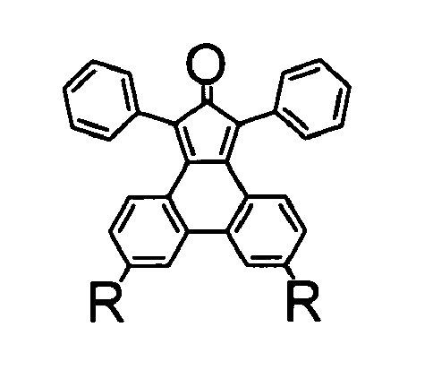
in a Diels-Alder cycloaddition to form a polytriphenylene dendrimer of the following formula (G01)
- For preparing polytriphenylene dendrimers of a higher order, said method further comprises
- a) reacting the polytriphenylene dendrimer of formula (G01)

with a deprotecting agent to form a polytriphenylene dendrimer of formula (G01)
- b) further reacting the dendrimer obtained in step a) with a tetraphenylcyclopentadienon or, preferably, with a 1,3-diphenylcyclopentaphenanthrenone of the formula (201)

- c) if the second generation polytriphenylene dendrimer comprises protected ethynyl groups R due to the presence of such groups in the diphenylcyclopentaphenanthrenone of the above formula (201) (or in the tetraphenylcyclopentadienon), optionally repeating steps a) and b) once or several times to form polytriphenylene dendrimers of a third or higher generation.
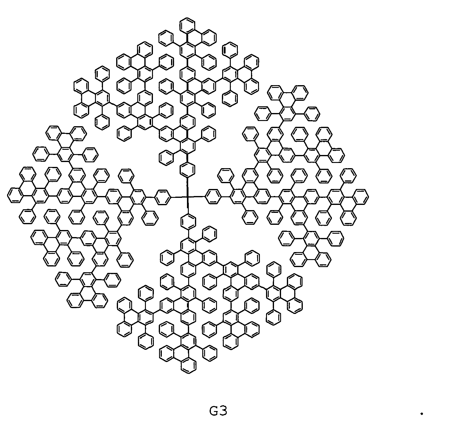
- Specifically, for the synthesis of the first-generation dendrimer G1 (Scheme 3) with four chromophores, the
phencyclone 7 ofScheme 3 was reacted with tetrakis(4-ethynylphenyl)methane in o-xylene at 170 °C in microwave reactor for 2-4 hours. After the removal of the excess of 7 by repetitive precipitation in methanol, the first-generation dendrimer G1 was recrystallized from a mixture of tetrachloroethane and hexane. The synthesis of the higher generation polytriphenylene dendrimers (Scheme 3) was carried out similarly following the corresponding synthetic protocol. Accordingly by the use of the AB2 branching agent 6 in iterative Diels-Alder/deprotection sequences dendrimers G2 with twelve triphenylene and G3 with twenty-eight triphenylene units could be synthesized in good yields. - Summarizing, the present invention provides a novel series of efficient pure blue emitting dendrimers. The synthesis from AB2 type building blocks to polytriphenylene dendrimers is non-catalyst and in quantitive yield. Most importantly, the twisted triphenylene units not only function as chromophores, but also effectively prevent the inter- or intramolecular fluorescence quenching, as proved by increased PLQY with increasing generation. These dendrimers exhibit stable and pure-blue emission in both PL and EL spectra and they could provide an avenue for dendritic emitters with the optimized EL efficiency/color purity trade-offs needed for pure blue light, which is still a great challenge in the field of blue-emitting materials.
- The present polytriphenylene dendrimers have applications in all technical fields where blue light emitters with the above favorable charactistics are needed. Such fields include generally opto-electronic devices and in particular organic LED devices, organic photodetectors, organic phototransistors, FET and solar cells.
- In a related aspect, therefore, the present invention provides also opto-electronic devices, and in particular LED devices, organic photodetectors, organic phototransistors, FET and photovoltaic cells, comprising the present polytriphenylene dendrimers. In a further related aspect of the present invention, an emissive layer comprising the present polytriphenylene dendrimers is provided.
- In opto-electronic devices as exemplified above, the dendrimers according to the present invention are used as electroluminescent material. The dendrimers may be present in the device, in particular the emissive layer, as the sole ligt emitting polymer or as a component in a blend further comprising hole and/or electron transporting polymers.
- In a preferred embodiment, the device comprises distinct layers of a dendrimer of the present invention, a hole transporting polymer and/or an electron transporting polymer. These layers will be located on a substrate between a charge injecting layer for injecting positive charged carriers, such as an anode electrode layer, and a charge injecting layer for injecting negative charge carriers, such as a cathode electrode layer. Additionally, charge transport layers may be provided between the emissive layer and one or both of the charge injecting layers.
- In one preferred embodiment, the opto-electronic device comprises an assembly of at least
- a) Hole injecting electrode (anode)
- b) Hole transporting layer
- c) Light emitting dendrimer of the invention
- d) Electron injecting electrode (cathode) on a transparent substrate.
- An example of such an assembly is depicted in
Fig. 5 . - In another preferred embodiment, additionally at least one hole blocking/ electron transporting layer is provided between c) and d).
- The anode may be of any material used in the art for this purpose. Suitable examples are metals, such as gold, silver, indium, iron, zinc, tin, metallic alloys such as magnesium/copper, aluminium/indium etc., semiconductors such as Si, Ge, etc., metallic oxides such as indium-tin-oxide or electroconducting polymers such as polyaniline etc. (for further examples see, e.g.
WO 2008/012250 ) . In a typical embodiment, the anode material is a mixed oxide of tin and indium (ITO) which is deposited on a transparent substrate such as glass, quartz or plastics, such as PET, so that the light emitted by the organic film comprising the emissive layer my be observed. The organic film may be the composite of several individual layers as outlined above, each designed for a distinct function. Since holes are injected from the anode, the layer next to the anode needs to have the functionality of transporting holes. Similarly, the layer next to the cathode needs to have the function of transporting electrons. The emissive layer comprising the present dendrimers can perform the combinded functions of electron transport and light emission. Still, an additional electron transporting layer may be present. - The hole transporting layer may comprise any polymer known in the art for this purpose (e.g. as disclosed in
WO 2008/012250 ). In a specific embodiment of the invention, the hole transporting layer comprises poly(3,4-ethylenedioxy thiophene) (PEDOT) and poly(styrene sulfonic acid) (PSS). - The optional electron transporting layer may comprise any low molecular weight materials or polymers known in the art for this purpose (e.g. as disclosed in
WO 2008/012250 ). Suitable compounds may be, e.g., 1,3,4-oxadiazoles or 1,3, 4-oxadiazole-containing polymers. In a specific embodiment of the invention, a layer of 4,4',4''-tris(N-3-methylphenyl-N-phenyl-amino)triphenylamine TPBi) is used. - The cathode material be of any material used in the art for this purpose (e.g. as disclosed in
WO 2008/012250 ). Some non-limiting examples are silver, aluminium, alkali metals, earth alkali metals, and alloys thereof, and electroconducting polymers such as polyprrrole, polythiophene etc. In a specific embodiment, the cathode is made of a Ca/Al alloy or CsF/Al. - The different layers may be deposited by any suitable method known in the art. For example, the PEDOT/PSS films and emissive dendrimer films may be spin-cast on the substrate and layers of metals or metallic alloys may be deposited by vapor deposition. Other suitable methods are e.g. disclosed in
WO 2008/012250 . - The invention is further illustrated by the following non-limiting Examples and Figures.
-
-
Fig. 1 . MALDI-Mass spectra for dendrimers G1, G2 and G3. -
Fig. 2 . Crystallographic structure of dendrimer G1. -
Fig. 3 . UV-vis absorption and PL spectra (λex = 300 nm) of dendrimers in chloroform solutions (a) and in solid states (b). -
Fig. 4 . I-V-L characteristics of an light emitting ITO/PEDOT:PSS/G2/TPBi(10nm)/CsF/Al device. Inset: normalized electroluminescence spectrum at 8V bias. -
Fig. 5 . Assembly of an exemplary OLED device:- 1) transparent substrate (e.g. glass)
- 2) Hole injecting electrode (e.g. ITO)
- 3) Hole transporting layer (e.g. PEDOT/PSS)
- 4) Light emitting dendrimer of the invention (e.g G2, G3)
- 5) Electron injecting electrode (e.g. Ca/Al or CsF/Al)
- The synthesis of the
intermediate compounds diphenylcyclopentaphenanthrenone 6 is shown inscheme 2 below.
- The synthesis started with the commercially available phenanthrene-9,10-dione which was brominated to give 3,6-dibromophenanthrene-9,10-
dione 2 in bromine. Due to the instability of the dione group during Hagihara-Sonogashira coupling, it was necessary to protect the dione group ofcompound 2 with dimethyl sulfate in order to provide 3,6-dibromo-9,10-dimethoxyphenanthrene 3 which subsquently was treated with ethynyltriisopropylsilane under Hagihara-Sonogashira conditions to afford 9,10-dimethoxy-3,6-bis((triisopropylsilyl)-ethynyl)phenanthrene 4. The dimethoxy group was cleaved via an efficient oxidation by using cerium ammonium nitrate (CAN) to yield 3,6-bis((triisopropylsilyl)ethynyl)phenanthrene-9,10-dione 5.
The final step under Knoevenagel condensation of 5 with 1,3-diphenylacetone gave the keyintermediate building block 6. - 3,6-dibromo-9,10-dimethoxyphenanthrene (3):
Compound 3 was prepared using a published procedure for related compounds. Compound 2 (4.25 g, 11.6 mmol), Bu4NBr (1.48 g, 4.6 mmol), Na2S2O4 (8.20 g, 47.0 mmol), THF (100 mL) and H2O (100 mL) were combined in a 500 mL round bottom flask and shaken for 5 min, after which dimethyl sulfate (7.5 mL, 79.5 mmol) was added, followed by aqueous sodium hydroxide (20 mL, 14.0 M). The mixture was stirred for 3 min, during which, 50 g of ice was added, then the mixture was additionally stirred for 15 minutes. The aqueous layer was separated and extracted with ethyl acetate (EtOAc) (3 × 750 mL) . The combined organic layers were washed with water (3 x 100 mL), NH4OH solution (2 × 500 mL) and brine (1 × 500 mL). The organic layer was dried with MgSO4, filtered and the solvents were removed under vacuum, resulting in a fluffy yellow solid. Washing the product with methanol (MeOH) gave a white solid. Additional impurities were removed by flashing the product through silica with a 1:1 mixture of hexanes and dichloromethane (DCM). Yield: 4.27 g, 10.8 mmol, 92%.
1H NMR (250 MHz, CD2Cl2) δ 8.69 (d, 2H, J = 1.8 Hz, aromatic CH), 8.10 (d, 2H, J = 8.8 Hz, aromatic CH), 7.72 (dd, 2H, J1 = 8.8 Hz, J2 = 1.8 Hz, aromatic CH), 4.06 (s, 6H, OCH 3); 13C NMR (62.5 MHz, CD2Cl2) δ 144.2, 130.9, 129.2, 128.8, 125.8, 124.5, 120.7, 61.3; FD-MS: m/z = 398.1 ([M]+). - 9,10-dimethoxy-3,6-bis((triisopropylsilyl)ethynyl)phenanthrene (4): Compound 3 (3.4 g, 8.6 mmol), Pd(PPh3)2Cl2 (0.68 g, 0.96 mmol), CuI (0.38 g, 2.0 mmol) and PPh3 (0.52 g, 2.0 mmol) were dissolved in 100 mL of toluene/triethylamine solution and degassed by three freeze/pump/thaw cycles. The solution was heated to reflux under argon, 5 mL (33.8 mmol) triisopropylsilylacetylene was added by syringe quickly to obtain a brown solution. The solution was kept stirring at 80 °C for 16 h. The solution was filtered and the solvent was removed by vacuum. After redissolution in DCM, the solution was washed with NH4Cl, 1M HCl, and NaHCO3. The organic phase was evaporated and purified by column chromatography (silica gel, PE: DCM = 4:1). Yield: 4.32 g, 7.22 mmol, 84%.
1H NMR (250 MHz, CD2Cl2) δ 8.73 (s, 2H, aromatic CH), 8.14 (s, 2H, J = 8.5 Hz, aromatic CH), 7.68 (d, 2H, J1 = 8.4 Hz, aromatic CH), 4.07 (s, 6H, OCH 3), 1.19 (s, 42H, TiPS CH2 and CH 3); 13C NMR (62.5 MHz, CD2Cl2) δ 144.9, 130.7, 129.5, 128.0, 126.8, 122.6, 121.4, 107.8, 92.0, 61.3, 18.9, 11.8; MALDI-TOF: m/z = 598.5 ([M]+). - 3,6-bis((triisopropylsilyl)ethynyl)phenanthrene-9,10-dione (5): Compound 4 (2.80 g, 4.6 mmol) was dissolved in acetonitrile (20 mL) and DCM (20 mL) under argon protection, then the mixture was added with stirring ammonium cerium (IV) nitrate (6.20 g, 11. 4 mmol) in water (60 mL) over 15 min. The reaction was diluted with 100 mL H2O and extracted with 3 × 100 mL DCM, and the organic phase was concentrated and purified by column chromatography (silica gel, PE: DCM = 1:1), affording an orange powder. Yield: 2.24 g, 3. 94 mmol, 84%.
1H NMR (250 MHz, CD2Cl2) δ 8.12 (d, 2H, J1 = 1.9 Hz, aromatic CH), 8.10(s, 2H, aromatic CH), 7.56 (d, 2H, J1 = 8.1 Hz, aromatic CH), 1.18 (s, 36H, silyl CH3), 1.17 (s, 6H, CH 2); 13C NMR (62.5 MHz, CD2Cl2) δ 197.9, 144.9, 130.7, 129.5, 128.0, 126.8, 122.6, 121.4, 107.8, 92.0, 18.9, 11.8; FD-MS: m/z = 568.8 ([M]+). - 1,3-diphenyl-6,9-bis((triisopropylsilyl)ethynyl)-cyclopenta-phenanthrenone (6): Compound 5 (1.36 g, 2.4 mmol) and 1,3-diphenyl-2-propanone (0.75 g, 3.6 mmol) were dissolved in anhydrate MeOH (50 mL) under argon atmosphere, 0.14 g KOH methanolic solution was added dropwise, and the mixture was heated up to 80 °C for 5 min. The brown color mixture was fast frozen to 0 °C and 1.9 mL HCl (1.25 M in MeOH) was added with stirring to neutralize the pH to 5. The green precipitated was filtered, washed with cold MeOH and purified by colunm chromatography (silica gel, PE:DCM = 2:1), affording a dark green powder. Yield: 1.08 g, 1.45 mmol, 61%. 1H NMR (250 MHz, CD2Cl2) δ 7.92 (s, 2H, aromatic CH), 7.48 (s, 2H, aromatic CH), 7.43 (dd, 4H, J1 = 9.7 Hz, J2 = 2.2 Hz, aromatic CH), 7.40 (s, 2H, aromatic CH), 7.34 (dd, 4H, J1 = 9.4 Hz, J2 = 1.6 Hz, aromatic CH), 7.03 (dd, 2H, J1 = 9.6 Hz, J2 = 1. 3 Hz, aromatic CH), 1.14 (s, 42H, silyl CH3 and CH 2); 13C NMR (62.5 MHz, CD2Cl2) δ 197.8, 147.4, 137.8, 136.2, 134.4, 133.0, 132.6, 132.1, 130.2, 129.0, 128.7, 128.6, 128.2, 127.1, 126.7, 124.2, 123.8, 106.8, 94.9, 93.9, 18.8, 11.7; FD-MS: m/z = 743.7 ([M]+).
- The synthesis of the 1st generation dendrimers G1, 8 and 9 is shown in
Scheme 3.
- Tetrakis(4-ethynylphenyl)methane (0.060g, 0.144 mmol) and 7 (0.440 g, 1.152 mmol,) were put under Argon, dissolved in o-xylene (2 mL) in a microwave tube and stirred at 170 °C for 4 h. After cooling to RT, the reaction mixture was precipitated in MeOH, then washed with DCM till the green color disappeared, affording a white powder. Yield: 0.255 g, 0.140 mmol, 97%.
1H NMR (700 MHz, C2D2Cl4) δ 8.35 (t, 8H, , J = 7.1 Hz, aromatic H1), 7.69 (s, 4H, aromatic H2), 7.64 (d, 4H, J = 8.5 Hz, aromatic H3), 7.50 (t, 12H, , J = 8.8 Hz, aromatic H4), 7.40 - 7.32 (n.r., 20H), 7.12 (d, 4H, J = 7.3 Hz, aromatic H5), 7.08 (t, 4H, J = 14.8 Hz, aromatic H6), 7.04 (d, 12H, J = 7.4 Hz, aromatic H7), 6.96 (t, 4H, J = 7.7 Hz, aromatic H8), 6.89 (d, 8H, J = 8.2 Hz, aromatic H9), 6.81 (d, 8H, J = 8.2 Hz, aromatic H10); 13C NMR (125 MHz, C2D2Cl4) δ 145.0, 144.8, 144.7, 142.5, 142.4, 142.4, 140.6, 140.3, 140.1, 140.0, 139.9, 138.6, 137.4, 137.0, 132.8, 132.5, 132.4, 132.2, 132.0, 131.92, 131.7, 131.5, 131.1, 131.1, 130.8, 130.5, 130.4, 130.2, 130.0, 129.5, 129.4, 129.3, 129.2, 129.1, 128.8, 128.7, 128.7, 127.7, 127.6, 127.5, 127.4, 127.3, 127.0, 126.9, 126.7, 125.9, 125.5, 124.8, 123.5; MALDI-TOF (Ag+): m/z = 1941.1 ([M+Ag]+). - Tetrakis (4-ethynylphenyl) methane (0.042 g, 0.100 mmol) and 6 (0.350 g, 0.472 mmol,) were put under Argon, dissolved in o-xylene (2 mL) in a microwave tube and stirred at 170 °C for 4 h. After cooling to RT, the reaction mixture was evaporated in vacuo. The residue was further purified by column chromatography (silica gel, PE:DCM = 6:1), affording light yellow powder. Yield: 0.266 g, 0.081 mmol, 81%.
- 1H NMR (500 MHz, CD2Cl2) δ 8.55 (d, 8H, , J = 2.3 Hz, aromatic H1), 7.78 (s, 4H, aromatic H2), 7.64 (d, 4H, J = 8.7 Hz, aromatic H3), 7.52 (t, 12H, , J = 8.4 Hz, aromatic H4), 7.43 (dd, 12H, J1 = 3.2 Hz, J2 = 10.6 Hz, aromatic H5), 7.21 - 7.15 (n.r., 16H), 7.08 (d, 12H, J = 6.9 Hz, aromatic H6), 6.98 (d, 8H, J = 8.5 Hz, aromatic H7), 6.87 (d, 8H, J = 8.5 Hz, aromatic H8), 1.14 (s, 168H; TiPS); 13C NMR (125 MHz, CD2Cl2) δ 149.0, 148.7, 146.9, 146.4, 145.1, 145.0, 144.4, 144.3, 144.1, 143.4, 143.0, 141.8, 141.7, 137.7, 136.8, 136.7, 136.5, 136.3, 135.9, 135.7, 135.6, 135.3, 135.1, 134.7, 134.6, 134.4, 134.0, 133.9, 133.8, 133.8, 133.6, 133.5, 133.4, 133.2, 133.2, 132.3, 132.1, 132.0, 131.9, 131.5, 129.2, 126.4, 126.2, 111.9, 111.8, 96.6, 96.5, 23.3, 16.2; MALDI-TOF (Ag+): m/z = 3384.1 ([M+Ag]+).
- To a solution of 8 (0.063 g, 0.019 mmol) in THF (3 mL) was added dropwise a solution of TBAF (0.065 g, 0.250 mmol) in THF (2 mL). The reaction was stirred at RT for 1 h and precipitate in MeOH. The product was dissolved again in THF and repeatedly precipitated in MeOH three times, affording light yellow powder. Yield: 0.034 g, 0.016 mmol, 90%.
1H NMR (250 MHz, C2D2Cl4) δ 8.57 (s, 8H, aromatic H1), 7.80 (s, 4H, aromatic H2), 7.64 (d, 4H, J = 8.7 Hz, aromatic H3), 7.57 - 7.44 (n.r., 24H), 7.26-7.09 (n.r., 28H), 6.96 (d, 8H, J = 8.3 Hz, aromatic H9), 6.87 (d, 8H, J = 8.3 Hz, aromatic H10), 3.22 (d, 8H, J = 8.8 Hz, C≡CH); 13C NMR (75 MHz, C2D2Cl4) δ 144.3, 143.4, 141.3, 140.8, 138.7, 138.2, 137.0, 132.4, 131.7, 131.3, 131.1, 130.5, 130.4, 130.1, 129.9, 129.5, 129.4, 129.2, 128.9, 128.7, 128.5, 128.4, 128.3, 127.5, 127.1, 127.0, 126.8, 119.9, 119.6, 83.7, 83.6, 29.6; MALDI-TOF: m/z = 2028.4 ([M]+). - The synthesis of the 2nd generation dendrimers G2, 10 and 11 is shown in
Scheme 3 above. - Dendrimer 9 (0.040 g, 0.020 mmol) and compound 7 (0.122 g, 0.320 mmol, ) were dissolved in o-xylene (2 mL) in a microwave tube under Argon and stirred at 170 °C for 8 h. After cooling to RT, the reaction mixture was precipitated in MeOH, then further purified by a column chromatography (PE:DCM = 1:1), affording a light yellow powder. Yield: 0.090 g, 0.019 mmol, 94%.
1H NMR (700 MHz, CD2Cl2) δ 8.40 (d, 16H, , J = 7.8 Hz, aromatic H1), 8.06 (s, 8H, aromatic H2), 7.73 (s, 4H, aromatic H3), 7.67 (ss, 16H, aromatic H4), 7.52 - 7.31 (n.r., 84H), 7.16 (d, 16H, J = 7.2 Hz, aromatic H5), 7.10 - 6.94 (n.r., 76H), 6.87 (d, 8H, J = 8.2 Hz, aromatic H6), 6.61 (d, 4H, J = 8.5 Hz, aromatic H7), 6.55 (d, 4H, J= 8.7 Hz, aromatic H8); 13C NMR (125 MHz, CD2Cl2) δ 145.0, 144.8, 144.7, 142.5, 142.4, 142.4, 140.6, 140.3, 140.1, 140.0, 139.9, 138.6, 137.4, 137.0, 132.8, 132.5, 132.4, 132.2, 132.0, 131.9, 131.7, 131.5, 131.2, 131.1, 130.8, 130.5, 130.4, 130.2, 130.0, 129.5, 129.4, 129.3, 129.2, 129.1, 128.8, 128.7, 128.7, 127.7, 127.6, 127.5, 127.4, 127.3, 127.0, 126.9, 126.7, 125.9, 125.5, 124.8, 123.5; MALDI-TOF (Ag+): m/z = 4966.8 ([M+Ag]+). - Dendrimer 9 (0.034 g, 0.017 mmol) and compound 6 (0.280 g, 0.377 mmol, ) were dissolved in o-xylene (2 mL) in a microwave tube under Argon and stirred at 170 °C for 8 h. After cooling to RT, the reaction mixture was precipitated in MeOH, then further purified by a column chromatography (PE:DCM = 3:1), affording a light yellow powder. Yield: 0.113 g, 0.015 mmol, 88%.
1H NMR (700 MHz, CD2Cl2) δ 8.51 (s, 16H, aromatic H1), 8.05 (s, 8H, aromatic H2), 7.71 (t, 16H, J = 8.1 Hz, aromatic H3), 7.59 (dd, 12H, J1 = 4.1 Hz, J2 = 8.6 Hz, aromatic H4), 7.52 - 7.31 (n.r., 72H), 7.16 - 6.98 (n.r., 80H), 6.86 (d, 8H, J = 8.2 Hz, aromatic H5), 6.60 (d, 4H, J = 8.7 Hz, aromatic H6), 6.54 (d, 4H, J = 8.7 Hz, aromatic H7), 1.15 (s, 336H; TiPS); 13C NMR (62.5 MHz, CD2Cl2) δ 149.0, 148.7, 146.8, 146.4, 145.1, 145.0, 144.8, 144.7, 142.5, 142.4, 142.4, 140.6, 140.3, 140.1, 140.0, 139.9, 138.6, 137.4, 137.0, 132.8, 132.5, 132.4, 132.2, 132.0, 131.9, 131.7, 131.5, 131.2, 131.1, 130.8, 130.5, 130.4, 130.2, 130.0, 129.5, 129.4, 129.3, 129.2, 129.1, 128.8, 128.7, 128.7, 127.7, 127.6, 127.5, 127.4, 127.3, 127.0, 126.9, 126.7, 125.9, 125.5, 124.8, 123.5, 111.9, 111.8, 96.6, 96.5, 23.2, 16.4; MALDI-TOF (Ag+): m/z = 7850.3 ([M+Ag]+). - To a solution of 10 (0.110 g, 0.014 mmol) in THF (3 mL) was added dropwise a solution of TBAF (0.150 g, 0.575 mmol) in THF (2 mL). The reaction was stirred at RT overnight and poured into 50 mL DCM and 50 mL H2O. The organic phase was concentrated and purified by a column chromatography (PE:DCM=2:3), affording a light yellow powder. Yield: 0.070 g, 0.013 mmol, 94%.
1H NMR (250 MHz, CD2Cl2) δ 8.53 (s, 16H, aromatic H1), 8.06 (s, 8H, aromatic H2), 7.70 (d, 12H, J = 4.1 Hz, aromatic H3), 7.59 (d, 8H, J = 8. 6 Hz, aromatic H4), 7.52 - 7.29 (n.r., 76H), 7.16 - 6.96 (n.r., 84H), 6.84 (d, 8H, J = 8.0 Hz, aromatic H5), 6.55 (dd, 8H, J1 = 8.8 Hz, J2 = 16. 8 Hz, aromatic H6), 3.22 (d, 16H, J = 4.7 Hz, C=CH) ; 13C NMR (62.5MHz, CD2Cl2) δ 148.2, 146.8, 146.3, 145.0, 144. 3, 143.4, 143.0, 141.3, 140.9, 138.7, 137.8, 137.0, 136.7, 136.5, 135.9, 135.7, 135.6, 135.3, 135.1, 134.7, 134.6, 134.4, 134.0, 133.9, 133.8, 132.7, 132.6, 131.5, 131.4, 131.2, 130.2, 130.0.3, 132.1, 132.0, 131.9, 131.5, 129.9, 129.5, 129.4, 129.2, 128.9, 128.7, 128.5, 128.4, 128.3, 127.5, 127.1, 127.0, 126.8, 119.9, 119.6, 84.1, 83.8, 31.8; MALDI-TOF: m/z = 5042.5 ([M]+). - The synthesis of the exemplary 3rd generation dendrimer G3 is shown in
Scheme 3 above. - Dendrimer 11 (0.053 g, 0.010 mmol) and compound 7 (0.250 g, 0.654 mmol, ) were dissolved in o-xylene (3 mL) in a microwave tube under Argon and stirred at 170 °C for 8 h. After cooling to RT, the reaction mixture was precipitated in MeOH, then further purified by a GPC column using DCM as the eluent, affording a light yellow powder. Yield: 0.098 g, 0.019 mmol, 90%.
1H NMR (700 MHz, CD2Cl2) δ 8.41 - 8.34 (n.r., 32H), 8.02 (ss, 24H, aromatic H1), 7.74 (s, 4H, aromatic H2), 7.69 - 7.65 (n.r., 36H), 7.52 - 6.88 (n.r., 404H), 6.67 - 6.58 (n.r., 16H), 6.49 (dd, 8H, J1 = 8.7 Hz, J2 = 17.0 Hz, aromatic H3); 13C NMR (75 MHz, CD2Cl2) δ 144.7, 144.6, 142.4, 142.3, 142.1, 140.5, 140.2, 140.0, 139.9, 138.5, 137.0, 136.9, 132.9, 132.8, 132.3, 132.1, 131.9, 131.8, 131.6, 131.5, 131.4, 131.2, 131.1, 131.04, 130.8, 130.8, 130.7, 130.6, 130.6, 130.5, 130.4, 130.3, 130.1, 129.9, 129.6, 129.4, 129.2, 129.1, 129.0, 128.9, 128.7, 128.6, 128.5, 128.3, 128.3, 128.2, 128.1, 128.0, 127.9, 127.9, 127.9, 127.8, 127.5, 127.4, 127.4, 127.3, 127.2, 127.1, 126.9, 126.9, 126.8, 126.7, 126.7, 126.6, 126.5, 126.5, 125.8, 125.6, 125.5, 124.7, 124.6, 123.6, 123.5; MALDI-TOF (Ag+): m/z = 11009.8 ([M+Ag]+). -

- To investigate the influence of the peripheral shielding upon the optical properties of the dendrimers,
model compound Scheme 1 from tetraphenylcyclopentadienon (compound 12) and an ethynyl-functionalized phenyl ring. Another polyphenylene derivative, dendrimer G2' with a pentaphenyl shell at its periphery was also prepared according toScheme 4 via analogous Diels-Alder reactions using tetraphenylcyclopentadienon instead of compound (2) in the second step of the preparation. - Dendrimer G2' is an end capped version of the first generation dendrimer G1, which, however, due to the TTP end caps resembles almost a second generation dendrimer, only lacking the connection at the outmost phenyl rings. Therefore it consists of longer segments than the uncapped first generation species, but is supposed to be more twisted than the second generation dendrimer. Thus the end capped dendrimer G2' can be understood as a "link" between first and second generation.
- OLED devices were built in a sandwich geometry (glass/ITO/PEDOT:PSS/dendrimer/TPBi/CsF/Al). The ITO covered glass substrates for the OLEDs were thoroughly cleaned in a variety of organic solvents and exposed to an oxygen plasma dry cleaning step. PEDOT: PSS (Baytron P from Bayer Inc.) layers were spin-coated under ambient conditions and dried according to specifications by Bayer Inc. in argon atmosphere and vacuum. The emissive dendrimer films were spin-cast from a 10 g/l toluene (or chlorobenzene) solution and dried at 80 °C for 2 hours in high vacuum conditions. Afterwards, a 10 nm layer of 4,4',4''-Tris(N-3-methylphenyl-N-phenyl-amino)triphenylamine (TPBi; LT-E302 from Rubipy Scientific Inc.) as hole blocking/electron transport layer was evaporated onto the emissive film at a pressure of 4 x 10⁻⁶ mbar. Finally, a thin layer (1 nm) of CsF and aluminum electrodes (100 nm) were evaporated on top of the device via physical vapor deposition at a base pressure of below 2 x 10⁻⁶ mbar.
- Dendrimers G2, G3, and G2' are readily soluble in chloroform, toluene and tetrahydrofuran (THF), which facilitates the final characterization and confirmation of their structures and purity by NMR spectroscopy and MALDI-TOF spectrometry. MALDI-TOF mass spectra exhibits single intense signals corresponding to the calculated masses of the target dendrimers G1, G2, and G3, as shown in
Fig. 1 . - Single crystals of G1, suitable for X-ray structure analysis, were grown from the tetrachloroethane and hexane mixtures at room temperature by slow evaporation. The crystal structure is well resolved; it possesses high symmetry and respects little conformational flexibility (
Fig. 2 ). The molecules arrange in an orthorhombic lattice. Each dendrimer has four twisted triphenylene units. The intermolecular distance between two dendrimers is about 3.209 Å. In contrast to most other triphenylene derivatives the inter-dendrimer chromophore-chromophore quenching is thus much reduced. - The UV-vis absorption and photoluminescence properties of all dendrimers were investigated in chloroform solutions (10-3 g/l) and solid states. PL excitation spectra were measured using a Shimadzu RF-5301 PC spectrofluorometer. Optical absorption measurements were carried out using a Perkin-Elmer Lambda 9 spectrophotometer. Photoluminescence quantum yield (PLQY) was measured from 10-3 g/l chloroform solutions by a relative method using quinine sulfate in sulfuric acid solution as a standard. The acquired data are summarized in Table 1.
- As shown in
Figure 3a , the spectra of the 1,2,4-triphenyltriphenylene (TTP) molecule and the first generation dendrimer (G1) are almost alike in shape and emission and absorption maxima, which is attributed to the fact that the absorbing and light emitting chromophore units are identical in both cases (TTPs). Dendrimers G2 and G3, on the other hand, are increasingly red-shifted in emission and absorption as a consequence of the increasing number of neighboring TTP units on each branch of the molecule. This does lead to an increased Π-orbital overlap of TTP units of different generations and therefore increases the effective conjugation in the entire molecule. G2', which is an end capped version of the first generation dendrimer has its absorption and emission spectra situated well between that of G1 and G2. In fact, a closer look at the chemical structures reveals that G2' resemble almost a second generation dendrimer, only lacking the connection at the outmost phenyl rings. For the investigation of possible aggregations PL measurements of different toluene dilutions of all five materials were performed. Over 3 orders of magnitude (10-4, 10-3, and 10-2 g/l) no concentration dependent effects are observable in any spectra, what is an argument against the formation of excimers or emission artifacts from aggregations. Apparently, the chromophores of different dendrimers are not interacting. Photoluminescence quantum yield measurements (PLQY) in solution reveal an increasing yield scaling with the size of molecules (Tab. 1). This indicates that central chromophores in the larger molecules are more effectively shielded against quenchers than the monomer or in a lower dendrimer generation, where more units are accessible to dynamic quenching. -
Figure 3b shows absorption and PL emission spectra of thin films spun from 1 g/L toluene solution leading to films with a thickness of typically 15 nm. Like in solutions, TTP and G1 appear very similar with only a bathochromic shift of 1 to 6 nm compared to solution spectra. Dendrimers G2 and G3, however, display a more pronounced shift of 17 to 18 nm as compared to solution spectra. In addition, dendrimer G3 also exhibits a stronger pronounced long wavelength tail than the other investigated samples of the 1st and 2nd generation. This leads to the conclusion that solid state packing can lead to increased coupling of individual TTP units from different generations, due to reduced inter TTP units twisting leading to an increased effective conjugation and a more pronounced spectral relaxation behavior in the solid state. Like observed before, the PL spectrum of the G2' is located right between G1 and G2 with a peak shift of approximately 10 nm. - Table 1 shows a direct comparison of absorption and PL peak positions in solution and thin film. As mentioned in PL, the peakmaxima display an increasing red shift with larger size of the molecules, both in solution and thin film. This bathochromic shift scales with the size of the molecules, which is most likely caused by an increased ability of larger molecules to flatten out in thin films, thus increasing the effective conjugation. It is worth mentioning that G2 displays a larger red shift compared to G2'. This means that the end caps of dentrimer G1 seem to stay more twisted in films than the additional triphenylene units on dendrimer G2. Also remarkable is the huge stokes shift of more than 100 nm for all samples, which is indicative for a rather large difference in the ground- and excited state configuration. The large stokes shift in all samples is caused by the fact that absorption happens mainly from S0 → S4 and emission from S1 → S0.
- Amongst the investigated dendrimers G2 and G2' exhibit the best thermal stability as well as good and acceptable, respectively, PLQYs and therefore these two materials were in details tested for their electroluminescent (EL) properties in different device geometries despite the fact that all different generations of dendrimers in principle exhibit EL emission. Since first tests showed certain instabilities at the cathode interface, an additional electron transport/hole blocking layer was applied and the organic light-emitting diodes (OLEDs) and the following geometry was used: ITO/PEDOT:PSS/Dendrimer/TPBi/CsF/Al.
- As depicted in
Figure 4 , OLEDs from G2 show a favorable blue electroluminescence spectrum with a maximum at 430 nm and a shape similar to photoluminescence. Luminance values of 300 cd/m2 are found at a bias voltage of 8 V and color coordinates of the emission are in a readily visible blue region with CIE 1931 value of (0.19, 0.18). The device displayed an onset of electroluminescence at approximately 6 V and maximum efficiencies of 0.4 cd/A. Figure S2 displays the characteristics of a G2' device. The normalized EL spectrum resembles the thin film PL spectrum very well and is located in a deeper blue region than TP-G2 with a maximum at 415 nm. At 10 V driving voltage, a maximum luminance of 400 cd/m2 can be found with an efficiency of 0.1 cd/A. Compared to G2 this lower efficiency is due to the fact that a remarkable part of the EL spectrum is in the UV region and does not contribute to the luminance value. The corresponding CIE1931 coordinate of G2' is (0.17, 0.10). Like for G2, applying higher voltages above 10 V does not lead to higher luminance, but starts degradation of the material. In terms of stability, however, these devices are not yet optimized. Although the hole blocking/electron transport layer already led to increased stability, an additional electron transporter could be incorporated into the active layer in order to get a more balanced carrier injection and thus lower onsets, higher efficiencies and an improved overall performance. - EL spectra (intensity per wavelength interval) were recorded using an ORIEL Multispec spectrometer with an attached ANDOR DB401-UV CCD camera. The current / luminance / voltage (ILV) characteristics were recorded in a customized setup using a Keithley 236 source measure unit for recording the current / voltage characteristics while recording the luminance using a calibrated photodiode attached to an integrating Ulbrich sphere.
Table 1. Optical Data for Dendrimers and Model Compounds Sample # 

Quantum yield [%]a Solution Thin film Solution Thin film TTP 289 298 401 402 3.8 G1 283 293 400 406 6.6 G2 304 312 414 431 27.0 G3 299 313 424 442 35.2 G2' 312 317 408 418 14.8 a relative to quinine sulfate dihydrate - PLQY measurements in solution reveal an increasing yield scaling with the size of molecules. This indicates that central chromophores in the larger molecules are more effectively shielded against quenchers than the monomer or small dendrimers, where more units are accessible to dynamic quenching.
Claims (16)
- A polytriphenylene dendrimer comprising a core unit with linked diphenyltriphenylene repeating units of the following formula (1)

- The polytriphenylene dendrimer according to claim 1, wherein each R' independently is H or a substitent selected from the group consisting of aryl, substituted aryl, heteroaryl, substituted heteroaryl, alkyl, alkylaryl, amino, halo, OH, carboxy, alkoxy, ester, and each R independently is H, a substituent selected from the group consisting of aryl, substituted aryl, heteroaryl, substituted heteroaryl, alkyl, alkylaryl, amino, halo, OH, carboxy, alkoxy, ester, an ethynyl group or protected ethynyl group, or a diphenyltriphenylene unit of said formula (1).
- The polytriphenylene dendrimer according to claim 1 or 2, comprising one of the following structures


- The polytriphenylene dendrimer according to claim 3, comprising a compound of the following formulae (G01) or (G02)

- The polytriphenylene dendrimer according to claim 4 having the formula

- A polytriphenylene dendrimer acccording to any one of claims 1-5, capable of blue light electroluminescence emission.
- A method for synthesisizing a polytriphenylene dendrimer comprising:reacting a compound comprising at least 2, 3 or 4reactive ethynylphenyl groups and a 1,3-diphenylcyclopentaphenanthrenone of the formula (2)wherein each R' independently is H or a substituent which does not participate in a Diels-Alder reaction, and
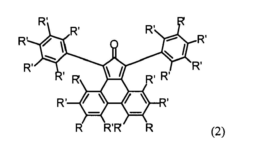
each R independently is H, a substituent which does not participate in a Diels-Alder reaction, or a protected ethynyl group,
in a Diels-Alder cycloaddition to form a polytriphenylene dendrimer. - The method according to claim 7, wherein both R in formula (2) are the same and the resulting polytriphenylene dendrimer has one of the structures of claim 3.
- The method according to claim 7 or 8, wherein both R in formula (2) are a protected ethynyl group and the Diels-Alder cycloaddition results in a first generation polytriphenylene dendrimer comprising protected ethynyl groups R, and which method further comprisesa) deprotecting the ethynyl groups andb) reacting the deprotected ethynyl groups with the 1,3-diphenylcyclopentaphenanthrenone of the formula (2) as defined in claim 7 or 8 in a Diels-Alder cycloaddition to form a second generation polytriphenylene dendrimer and,c) if the second generation polytriphenylene dendrimer comprises protected ethynyl groups R due to the presence of such groups in the diphenylcyclopentaphenanthrenone of the above formula (2) used in step b), optionally repeating steps a) and b) once or several times to form polytriphenylene dendrimers of a third or higher generation.
- The method according to claim 9, wherein the substituents R of the diphenylcyclopentaphenanthrenone of formula (2) used in step b) and/or step c) are the same.
- The method according to any one of claims 8-10 comprising:reacting tetrakis(4-ethynylphenyl)methane and a 1,3-diphenylcyclopentaphenanthrenone of the formula (201)wherein all substituents R are the same and selected from H, an ethynyl group or protected ethynyl group,
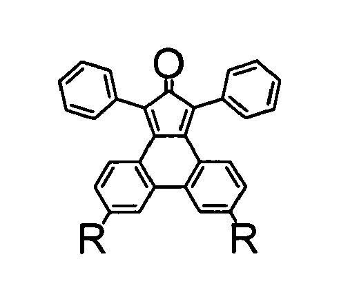
in a Diels-Alder cycladdition to form a polytriphenylene dendrimer of the following formula (G01)
- The method according to claim 11, further comprisinga) reacting the polytriphenylene dendrimer of formula (G01)

with a deprotecting agent to form a polytriphenylene dendrimer of formula (G01) b) further reacting the dendrimer obtained in step a) with a 1,3-diphenylcyclopentaphenanthrenone of the formula (201)
to form a second generation polytriphenylene dendrimer, andc) if the second generation polytriphenylene dendrimer comprises protected ethynyl groups R due to the presence of such groups in the diphenylcyclopentaphenanthrenone of the above formula (201), optionally repeating steps a) and b) once or several times to form polytriphenylene dendrimers of a third or higher generation. - A method for synthesizing the diphenylcyclopentaphenanthrenone of formula (2) as defined in claim 7
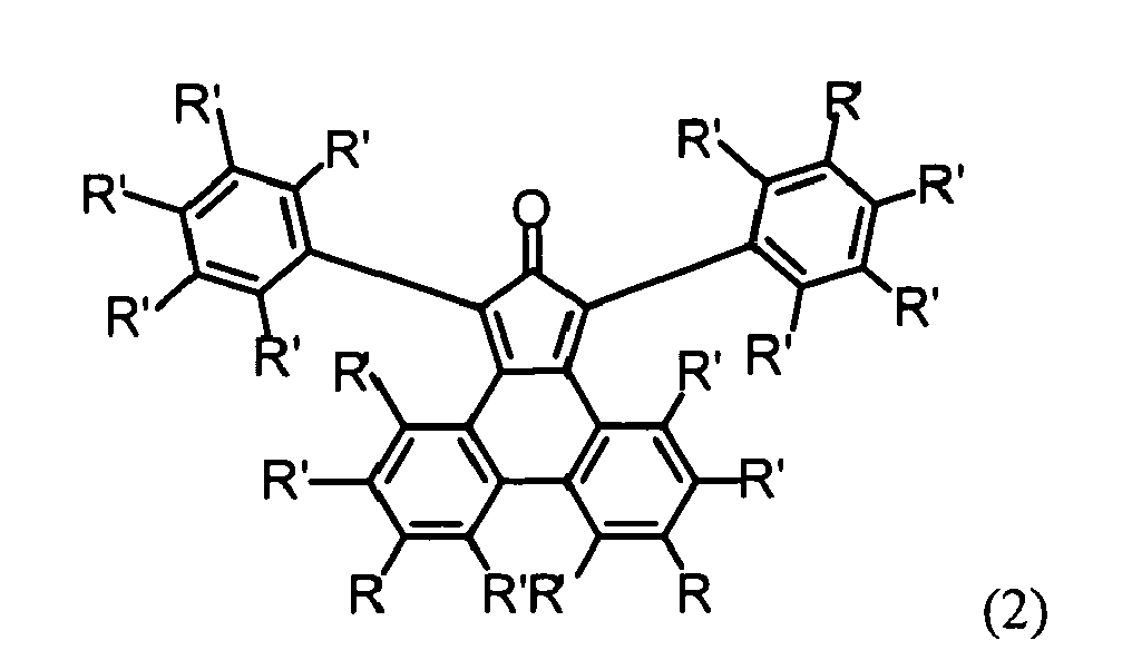 a) brominating an unsubstituted or substituted phenanthrene-9,10-dione to give the corresponding 3,6-dibromophenanthrene-9,10-dione;b) protecting the dione group with a protecting agent, e.g. dimethylsulfate, to give a protected derivative, e.g. 3,6-dibromo-9,10-dimethoxyphenanthrene;c) reacting the product of step b), e.g. 3,6-dibromo-9,10-dimethoxyphenanthrene, with a compound providing a protected ethynyl group, e.g. ethynyltriisopropylsilane or ethynyltrimethylsilane, to give the corresponding ethynyl-functionalized product, e.g. 9,10-dimethoxy-3,6-bis-(triisopropylsilyl)ethynyl)phenanthrene or 9,10-dimethoxy-3,6-bis(trimethylsilyl)ethynyl)phenanthrene;d) removing the methoxy groups or other protecting groups of step b) by reacting with an oxidating agent to give a 3,6-bis(triisopropylsilyl)ethynyl)phenanthrene-9,10-dione or an analogon with another ethynyl-protecting group;e) reacting the product of step d) with 1,3-diphenylacetone under Knoevenagel condensation to give the diphenylcyclopentaphenanthrenone of the above formula (2) wherein each R is a protected ethynyl group, e.g. a triisopropylsilylethynyl or trimethylsilylethynyl group, andf) optionally removing the protecting groups, e.g. triisopropylsilyl groups, to give the diphenylcyclopentaphenanthrenone of the above formula (2) wherein each R is an ethynyl group.
 - An emissive layer comprising the polytriphenylene dendrimer according to any one of claims 1-6.
- Use of the polytriphenylene dendrimer according to any one of claims 1-6 or of the emissive layer of claim 14 in opto-electronic devices such as organic LED devices, organic photodetectors, organic phototransistors, FET and photovoltaic cells.
- An opto-electronic device, in particular an organic LED device, an organic photodetector, organic phototransistor, FET or a photovoltaic cell, comprising a polytriphenylene dendrimer according to any one of claims 1-6 or an emissive layer according to claim 14.
Priority Applications (1)
| Application Number | Priority Date | Filing Date | Title |
|---|---|---|---|
| EP08008782A EP2143775A1 (en) | 2008-05-09 | 2008-05-09 | Blue light emmiting polythriphenylene dendrimers, methods of preparation and uses thereof |
Applications Claiming Priority (1)
| Application Number | Priority Date | Filing Date | Title |
|---|---|---|---|
| EP08008782A EP2143775A1 (en) | 2008-05-09 | 2008-05-09 | Blue light emmiting polythriphenylene dendrimers, methods of preparation and uses thereof |
Publications (1)
| Publication Number | Publication Date |
|---|---|
| EP2143775A1 true EP2143775A1 (en) | 2010-01-13 |
Family
ID=39791696
Family Applications (1)
| Application Number | Title | Priority Date | Filing Date |
|---|---|---|---|
| EP08008782A Withdrawn EP2143775A1 (en) | 2008-05-09 | 2008-05-09 | Blue light emmiting polythriphenylene dendrimers, methods of preparation and uses thereof |
Country Status (1)
| Country | Link |
|---|---|
| EP (1) | EP2143775A1 (en) |
Cited By (3)
| Publication number | Priority date | Publication date | Assignee | Title |
|---|---|---|---|---|
| US20140231754A1 (en) * | 2013-02-20 | 2014-08-21 | Feng-wen Yen | Ditriphenylene derivative and organic electroluminescent device using the same |
| CN113603716A (en) * | 2021-07-20 | 2021-11-05 | 山东硅科新材料有限公司 | Polycyclic aromatic hydrocarbon silane coupling agent with strong fluorescence characteristic and green efficient preparation and application thereof |
| CN113817140A (en) * | 2021-09-26 | 2021-12-21 | 中电科技集团重庆声光电有限公司 | Dendritic polymer and preparation method thereof |
Citations (3)
| Publication number | Priority date | Publication date | Assignee | Title |
|---|---|---|---|---|
| US20050048318A1 (en) * | 2001-02-22 | 2005-03-03 | Canon Kabushiki Kaisha | Organic luminescence device with a fused polynuclear compound |
| WO2006130598A2 (en) | 2005-05-31 | 2006-12-07 | Universal Display Corporation | Triphenylene hosts in phosphorescent light emitting diodes |
| WO2008012250A1 (en) | 2006-07-28 | 2008-01-31 | Ciba Holding Inc. | Novel polymers |
-
2008
- 2008-05-09 EP EP08008782A patent/EP2143775A1/en not_active Withdrawn
Patent Citations (3)
| Publication number | Priority date | Publication date | Assignee | Title |
|---|---|---|---|---|
| US20050048318A1 (en) * | 2001-02-22 | 2005-03-03 | Canon Kabushiki Kaisha | Organic luminescence device with a fused polynuclear compound |
| WO2006130598A2 (en) | 2005-05-31 | 2006-12-07 | Universal Display Corporation | Triphenylene hosts in phosphorescent light emitting diodes |
| WO2008012250A1 (en) | 2006-07-28 | 2008-01-31 | Ciba Holding Inc. | Novel polymers |
Non-Patent Citations (6)
| Title |
|---|
| BAUER ET AL., TOP. CURR. CHEM., vol. 245, 2005, pages 253 |
| FREUDENMANN ET AL., J. MAT. CHEM., vol. 11, 2001, pages 1618 |
| HORNIG F S, KORTH H-G, RAUEN U, DE GROOT H, SUSTMAN R: "synthesis and properties of pH-insensitive fluorescent nitric oxide cheletropic trap (FNOCT)", HELVETICA CHIMICA ACTA, vol. 89, 2006, pages 2281 - 2296, XP002558081 * |
| L'ESPERANCE R P, VAN VEGEN D, DAYAL R, PASCAL R A JR: "A study of Substituent Effects on Hydrogen-to-Arene Nonbonded Interactions", JOURNAL OF ORGANIC CHEMISTRY, vol. 56, 1991, pages 688 - 694, XP002499535 * |
| ROLAND E BAUER ET AL: "Functionalised Polyphenylene Dendrimers and Their Applications", TOPICS IN CURRENT CHEMISTRY, SPRINGER, BERLIN, DE, vol. 245, 1 January 2005 (2005-01-01), pages 253 - 286, XP008097400, ISSN: 0340-1022 * |
| VON WALTER R ET AL: "Über die Synthese von Mono-, Bis- und Tris-äthinyl-Aromaten und ihre Reaktionen mit Cyclopentadienonen", JUSTUS LIEBIGS ANNALEN DER CHEMIE, VERLAG CHEMIE GMBH, WEINHEIM,; DE, vol. 739, 1 January 1970 (1970-01-01), pages 159 - 165, XP008097448, ISSN: 0075-4617 * |
Cited By (5)
| Publication number | Priority date | Publication date | Assignee | Title |
|---|---|---|---|---|
| US20140231754A1 (en) * | 2013-02-20 | 2014-08-21 | Feng-wen Yen | Ditriphenylene derivative and organic electroluminescent device using the same |
| US9166177B2 (en) | 2013-02-20 | 2015-10-20 | Feng-wen Yen | Ditriphenylene derivative and organic electroluminescent device using the same |
| CN113603716A (en) * | 2021-07-20 | 2021-11-05 | 山东硅科新材料有限公司 | Polycyclic aromatic hydrocarbon silane coupling agent with strong fluorescence characteristic and green efficient preparation and application thereof |
| CN113603716B (en) * | 2021-07-20 | 2024-03-19 | 山东硅科新材料有限公司 | Polycyclic aromatic hydrocarbon silane coupling agent with strong fluorescence characteristic and green efficient preparation and application thereof |
| CN113817140A (en) * | 2021-09-26 | 2021-12-21 | 中电科技集团重庆声光电有限公司 | Dendritic polymer and preparation method thereof |
Similar Documents
| Publication | Publication Date | Title |
|---|---|---|
| EP1080162B1 (en) | Emissive polymers and devices incorporating these polymers | |
| Zhou et al. | Binaphthyl‐containing green‐and red‐emitting molecules for solution‐processable organic light‐emitting diodes | |
| Bonardi et al. | Fine‐tuning of yellow or red photo‐and electroluminescence of functional difluoro‐boradiazaindacene films | |
| US6824890B2 (en) | Soluble tetrahedral compounds for use in electroluminescent devices | |
| Yang et al. | High-T g carbazole derivatives as a new class of aggregation-induced emission enhancement materials | |
| Wang et al. | The synthesis and photoluminescence characteristics of novel blue light-emitting naphthalimide derivatives | |
| Anderson et al. | Benzofuran trimers for organic electroluminescence | |
| EP2121573A1 (en) | Arylamine compounds and electronic devices | |
| Yu et al. | Synthesis, characterization and high-efficiency blue electroluminescence based on coumarin derivatives of 7-diethylamino-coumarin-3-carboxamide | |
| Wettach et al. | Deep blue organic light-emitting diodes based on triphenylenes | |
| CN110386930B (en) | Aggregation-induced emission compound, preparation method and application thereof | |
| Zhang et al. | Synthesis, characterization, and electroluminescent properties of star shaped donor–acceptor dendrimers with carbazole dendrons as peripheral branches and heterotriangulene as central core | |
| Coya et al. | Synthesis and tunable emission of novel polyfluorene co-polymers with 1, 8-naphthalimide pendant groups and application in a single layer–single component white emitting device | |
| Wang et al. | Twisted penta‐Carbazole/Benzophenone Hybrid Compound as Multifunctional Organic Host, Dopant or Non‐doped Emitter for Highly Efficient Solution‐Processed Delayed Fluorescence OLEDs | |
| EP1281744B1 (en) | Emissive polymers and devices incorporating these polymers | |
| Sun et al. | Multi-substituted dibenzo [a, c] phenazine derivatives as solution-processable thermally activated delayed fluorescence materials for orange–red organic light-emitting diodes | |
| Huang et al. | Construction of deep-blue AIE luminogens with TPE and oxadiazole units | |
| EP2143775A1 (en) | Blue light emmiting polythriphenylene dendrimers, methods of preparation and uses thereof | |
| Shi et al. | Two novel phenylethene-carbazole derivatives containing dimesitylboron groups: Aggregation-induced emission and electroluminescence properties | |
| Liu et al. | Carbazole-based multiple resonance dendrimers with narrowband blue emission for solution-processed OLEDs | |
| Wang et al. | A novel heteroterfluorene for efficient blue and white OLEDs | |
| Ren et al. | Synthesis and properties of novel spirobifluorene-cored dendrimers | |
| KR20130046632A (en) | Electriluminescent polymer containing benzothiadiazole derivatives and organoelectriluminescent device emloying the same | |
| Bai et al. | Synthesis, Photophysical Properties and Near Infrared Electroluminescence of 1 (4), 8 (11), 15 (18), 22 (25)‐Tetra‐(methoxy‐phenoxy) phthalocyanine | |
| Jin et al. | Synthesis and properties of various PPV derivatives with phenyl substituents |
Legal Events
| Date | Code | Title | Description |
|---|---|---|---|
| PUAI | Public reference made under article 153(3) epc to a published international application that has entered the european phase |
Free format text: ORIGINAL CODE: 0009012 |
|
| PUAI | Public reference made under article 153(3) epc to a published international application that has entered the european phase |
Free format text: ORIGINAL CODE: 0009012 |
|
| 17P | Request for examination filed |
Effective date: 20090807 |
|
| AK | Designated contracting states |
Kind code of ref document: A1 Designated state(s): AT BE BG CH CY CZ DE DK EE ES FI FR GB GR HR HU IE IS IT LI LT LU LV MC MT NL NO PL PT RO SE SI SK TR |
|
| AX | Request for extension of the european patent |
Extension state: AL BA MK RS |
|
| R17C | First examination report despatched (corrected) |
Effective date: 20091228 |
|
| AKX | Designation fees paid |
Designated state(s): AT BE BG CH CY CZ DE DK EE ES FI FR GB GR HR HU IE IS IT LI LT LU LV MC MT NL NO PL PT RO SE SI SK TR |
|
| STAA | Information on the status of an ep patent application or granted ep patent |
Free format text: STATUS: THE APPLICATION IS DEEMED TO BE WITHDRAWN |
|
| 18D | Application deemed to be withdrawn |
Effective date: 20141202 |