EP2143185B1 - Method and device for capturing a fault in an electrical supply grid - Google Patents
Method and device for capturing a fault in an electrical supply grid Download PDFInfo
- Publication number
- EP2143185B1 EP2143185B1 EP07722371.7A EP07722371A EP2143185B1 EP 2143185 B1 EP2143185 B1 EP 2143185B1 EP 07722371 A EP07722371 A EP 07722371A EP 2143185 B1 EP2143185 B1 EP 2143185B1
- Authority
- EP
- European Patent Office
- Prior art keywords
- fault
- component
- virtual
- error
- components
- Prior art date
- Legal status (The legal status is an assumption and is not a legal conclusion. Google has not performed a legal analysis and makes no representation as to the accuracy of the status listed.)
- Active
Links
Images


Classifications
-
- H—ELECTRICITY
- H02—GENERATION; CONVERSION OR DISTRIBUTION OF ELECTRIC POWER
- H02H—EMERGENCY PROTECTIVE CIRCUIT ARRANGEMENTS
- H02H7/00—Emergency protective circuit arrangements specially adapted for specific types of electric machines or apparatus or for sectionalised protection of cable or line systems, and effecting automatic switching in the event of an undesired change from normal working conditions
- H02H7/26—Sectionalised protection of cable or line systems, e.g. for disconnecting a section on which a short-circuit, earth fault, or arc discharge has occured
- H02H7/28—Sectionalised protection of cable or line systems, e.g. for disconnecting a section on which a short-circuit, earth fault, or arc discharge has occured for meshed systems
-
- G—PHYSICS
- G01—MEASURING; TESTING
- G01R—MEASURING ELECTRIC VARIABLES; MEASURING MAGNETIC VARIABLES
- G01R31/00—Arrangements for testing electric properties; Arrangements for locating electric faults; Arrangements for electrical testing characterised by what is being tested not provided for elsewhere
- G01R31/50—Testing of electric apparatus, lines, cables or components for short-circuits, continuity, leakage current or incorrect line connections
- G01R31/52—Testing for short-circuits, leakage current or ground faults
-
- G—PHYSICS
- G01—MEASURING; TESTING
- G01R—MEASURING ELECTRIC VARIABLES; MEASURING MAGNETIC VARIABLES
- G01R31/00—Arrangements for testing electric properties; Arrangements for locating electric faults; Arrangements for electrical testing characterised by what is being tested not provided for elsewhere
- G01R31/08—Locating faults in cables, transmission lines, or networks
- G01R31/081—Locating faults in cables, transmission lines, or networks according to type of conductors
- G01R31/086—Locating faults in cables, transmission lines, or networks according to type of conductors in power transmission or distribution networks, i.e. with interconnected conductors
Definitions
- the invention relates to a method for detecting an error, in particular a ground fault, in an electrical supply network.
- a disadvantage of all known methods is that a simple and rapid location of a fault in an electrical supply network, the network configuration and the type of potential error must be present as input. This leads, for example, to the fact that other location methods are used in parallel or successively for the error monitoring of failure and non-failure-relevant errors, which is time-consuming and costly.
- EP-A-0 045 113 known in which so-called.
- Directional elements are used to determine an error position, which are obtained from a simulation.
- the prerequisite for this is the existence of a DC network model for the simulation.
- the object of the present invention is therefore to provide a method which does not have any selection with regard to Error indicators needed and especially in meshed supply networks is used.
- a component of the electrical supply network is connected to at least one supply line, wherein the component is combined with a part of the supply and discharge lines of the supply line to the component to a virtual component.
- the real components of the electrical supply network are considered, but artificially formed component of the supply network is formed and evaluated with regard to a possible error.
- each of the supply line connected to the component is assigned an error indicator within the virtual component and the direction of a possible error, in particular a ground fault, is determined.
- Each error indicator is then assigned a correlation coefficient depending on the direction of the error.
- the direction of the error is in the virtual component, advantageously the number +1; in case the direction of the error from the virtual component shows the number -1. If the error is undetectable, the number 0.5 will be assigned.
- the error indicators associated with the correlation coefficient are then combined to form an index of the virtual components.
- the highest index and thus the virtual component with the highest probability of error can be determined.
- the indices of the virtual components are calculated with respect to a respective functional group of components.
- the formation of the virtual components for the electrical supply network may be based on different considerations. For example, it is not necessary to use all the components of the supply network for the formation of the virtual components. For example, only all circuit breakers in the electrical supply network can be defined as components and thus corresponding virtual components can be formed. Other components are then considered as part of the supply line and not taken into account in the error calculation.
- the error indicators are weighted with regard to their display accuracy within the electrical supply network and correspond to an alphanumeric value.
- the error indicators of a virtual component are added and normalized with respect to the number of error indicators and thus result in a corresponding index of the virtual component.
- all mathematical methods for averaging are included.
- the virtual component with the highest index is automatically selected and / or visualized to a viewer. This ensures that the virtual component identified as having errors is made available to a viewer or a system for a more accurate check.
- the direction of a possible error within the considered section of the electrical supply network is determined at periodic intervals.
- the object is likewise achieved by a device for carrying out the method according to the invention.
- a computer program product solves the problem wherein the computer program product is stored in a computer readable medium and includes computer readable means for causing a computer to perform the inventive method when the program is run in the computer.
- FIG. 1a shows a virtual component 4a, in which a component 2a is connected to a direct entry and exit within the electrical supply network 1.
- the line supply and output of the component 2a is assigned an error indicator 3a, 3b within the virtual component 4a.
- a correlation coefficient 5a, 5b is assigned to each error indicator 3a, 3b, wherein the respective correlation coefficient 5a, 5b represents a probability of occurrence for a corresponding error indicator 3a, 3b within the virtual component 4a.
- the correlation coefficient 5a, 5b can either be assigned manually by an operator or automatically by a system based on the network structure of the electrical supply network 1 due to a possible error 7 (not shown)
- a further virtual component 4b adjoining a first virtual component 4a likewise again has an error indicator 3c on the connecting line 1 of the electrical supply network in the direction of the first virtual component 4a.
- a second virtual component 4b arranged below the first virtual component 4a would have an error indicator 3c directly to the error indicator 3b.
- each connection line between two components 2a, 2b is assigned two independent error indicators 3b, 3c. This has the advantage that a form of normalization of the error indicators 3a, 3b is made.
- FIG. 1b a differently composed virtual component 4a is shown.
- the supply line 1 of the electrical supply network serves as a connection.
- a possible error 7 on this section of the supply line 1 is determined by two error indicators 3b, 3c, which are respectively assigned to the components 2a, 2b.
- Each connection line is assigned an error indicator 3b, 3c, so that in the case of a connection of three components 2a to 2c via a Kotentician within the electrical supply network, the corresponding virtual component 4a has three error indicators 3a to 3c.
- the error indicators 3b, 3c with the corresponding correlation coefficients 5b, 5c as a whole are normalized for the virtual component 4a as an index 6a.
- a number -1 is given, in the case that the direction of the error 7 in the component 2a shows a number +1 as the correlation coefficient 5b.
- the virtual component 4a, in which the error occurs 7, thus contains only correlation coefficients 5b, 5c with the number +1, so that here is the highest error index 6a and thus the highest probability of the occurrence of an error 7 in this section of the electrical supply network ,
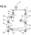
- the figure 2A shows a section of an exemplary supply network that is connected via two power switches 2a, 2i with a non-monitored main voltage line via a transformer 8.
- a transformer 8 In the present case, it is assumed that the circuit breakers 2a, 2i and the transformer 8 are not to be monitored with regard to possible errors 6.
- the electrical supply network to be monitored is subdivided into five virtual components 4a to 4e, which contain at least one component 2a to 2i and in which each supply or discharge of the supply line 1 is assigned an error indicator 3a to 31 (not shown).
- FIG. 2a is represented as +1 or -1 as a function of the direction of the error of the correlation coefficients 5a to 5i.
- the virtual component 4c has a node of the supply line 1 and thus three components 2c, 2d, 2e. Therefore, this virtual component 4c has three error indicators 3c, 2d, 3e associated with corresponding correlation coefficients 5c, 5d, 5e.
- the FIG. 3 shows a tabular representation of the relevant error indicators 5a to 5i of the virtual components 4a to 4e (in the table as art. Comp.1 to art. Comp.5).
- the individual components 2a to 2i are shown as Fl-green_1 to Fl_red_5.
- the error indicator 3c, 3d, 3e is multiplied by the value 100 multiplied by the correlation coefficients 5c, 5d, 5e in the form of +1 to a sum normalized by the Number of considered error indicators 5a to 5i in the present example has the highest error index 6c.
Landscapes
- Physics & Mathematics (AREA)
- General Physics & Mathematics (AREA)
- Supply And Distribution Of Alternating Current (AREA)
- Test And Diagnosis Of Digital Computers (AREA)
Description
Die Erfindung betrifft ein Verfahren zur Erfassung eines Fehlers, insbesondere eines Erdschlusses, in einem elektrischen Versorgungsnetz.The invention relates to a method for detecting an error, in particular a ground fault, in an electrical supply network.
Bisherige Verfahren zur Erfassung eines Fehlers innerhalb eines Energieversorgungsnetzes unterscheiden zwischen ausfallrelevanten Fehlern (Outage Faults) und zwischen nicht- ausfallrelevanten Fehlern (Non-Outage Faults). Für beide Arten von Fehlererkennungen ist ein unterschiedlicher Algorithmus notwendig.Previous methods for detecting an error within a power supply network differentiate between failure-relevant errors (outage faults) and between non-failure-related errors (non-outage faults). Both types of error detection require a different algorithm.
Des Weiteren ist bekannt, die Richtung eines möglichen Fehlers, insbesondere in Form eines Erdschlusses, zu ermittelt. So beschreibt exemplarisch die
Nachteilig bei allen bekannten Verfahren ist, dass eine einfache und schnelle Ortung eines Fehlers in einem elektrischen Versorgungsnetz die Netzkonfiguration und die Art des möglichen Fehlers als Eingangsgröße vorliegen muss. Dies führt beispielsweise dazu, dass für die Fehlerüberwachung von ausfall- und nichtausfallrelevanten Fehlern andere Ortungsverfahren parallel bzw. nacheinander verwendet werden, was zeit- und kostenaufwändig ist.A disadvantage of all known methods is that a simple and rapid location of a fault in an electrical supply network, the network configuration and the type of potential error must be present as input. This leads, for example, to the fact that other location methods are used in parallel or successively for the error monitoring of failure and non-failure-relevant errors, which is time-consuming and costly.
Aus der Druckschrift
Ferner ist die Druckschrift
Aufgabe der vorliegenden Erfindung ist es daher, ein Verfahren bereitzustellen, das keine Selektion hinsichtlich der Fehlerindikatoren benötigt und insbesondere in vermaschten Versorgungsnetzen zur Anwendung kommt.Furthermore, the document is
The object of the present invention is therefore to provide a method which does not have any selection with regard to Error indicators needed and especially in meshed supply networks is used.
Gelöst wird die Aufgabe durch den Gegenstand des Patentanspruchs 1. Danach ist vorgesehen, dass eine Komponente des elektrischen Versorgungsnetzes mit mindestens einer Versorgungsleitung verbunden ist, wobei die Komponente mit einem Teil der Zu- und Ableitungen der Versorgungsleitung zur Komponente zu einer virtuellen Komponente zusammengefasst wird. Im Rahmen des erfindungsgemäßen Verfahrens werden daher nicht die realen Komponenten des elektrischen Versorgungsnetzes betrachtet, sondern künstlich gebildete Komponente des Versorgungsnetzes gebildet und hinsichtlich eines möglichen Fehlers ausgewertet. Dazu wird jeder der mit der Komponente verbundenen Versorgungsleitung innerhalb der virtuellen Komponente ein Fehlerindikator zugeordnet und die Richtung eines möglichen Fehlers, insbesondere eines Erdschlusses, ermittelt.The object is achieved by the subject matter of
Jedem Fehlerindikator wird anschließend in Abhängigkeit von der Richtung des Fehlers ein Korrelationskoeffizient zugewiesen. Für den Fall, dass die Richtung des Fehlers in die virtuelle Komponente verläuft wird vorteilhafterweise die Zahl +1; für den Fall das die Richtung des Fehlers aus der virtuellen Komponente zeigt die Zahl -1 vergeben. Bei einer nicht feststellbaren Richtung des Fehlers wird die Zahl 0.5 vergeben.Each error indicator is then assigned a correlation coefficient depending on the direction of the error. In the event that the direction of the error is in the virtual component, advantageously the number +1; in case the direction of the error from the virtual component shows the number -1. If the error is undetectable, the number 0.5 will be assigned.
Die mit dem Korrelationskoeffizienten zugeordneten Fehlerindikatoren werden dann zu einem Index der virtuellen Komponenten zusammengefasst. Durch den Vergleich von zumindest zwei Indizes von virtuellen Komponenten kann der höchste Index und damit die virtuelle Komponente mit der höchsten Fehlerwahrscheinlichkeit ermittelt werden.The error indicators associated with the correlation coefficient are then combined to form an index of the virtual components. By comparing at least two indices of virtual components, the highest index and thus the virtual component with the highest probability of error can be determined.
Gemäß einer vorteilhaften Ausführung des Verfahrens ist vorgesehen, dass die Indizes der virtuellen Komponenten bezüglich jeweils einer funktionellen Gruppe von Komponenten berechnet werden. Die Bildung der virtuellen Komponenten für das elektrische Versorgungsnetz kann auf der Grundlage von unterschiedlichen Überlegungen erfolgen. So sind beispielsweise nicht notwendigerweise alle Komponenten des Versorgungsnetzes für die Bildung der virtuellen Komponenten zu nutzen. So können beispielsweise lediglich alle Leistungsschalter im elektrischen Versorgungsnetz als Komponenten definiert und damit entsprechende virtuelle Komponenten gebildet werden. Andere Komponenten werden dann als Teil der Versorgungsleitung aufgefasst und in der Fehlerberechnung nicht berücksichtigt.According to an advantageous embodiment of the method, it is provided that the indices of the virtual components are calculated with respect to a respective functional group of components. The formation of the virtual components for the electrical supply network may be based on different considerations. For example, it is not necessary to use all the components of the supply network for the formation of the virtual components. For example, only all circuit breakers in the electrical supply network can be defined as components and thus corresponding virtual components can be formed. Other components are then considered as part of the supply line and not taken into account in the error calculation.
Auch eine Unterscheidung zwischen ausfallrelevanten und nicht- ausfallrelevanten Komponenten mit entsprechend definierten virtuellen Komponenten des elektrischen Versorgungsnetzes ermöglicht eine Fehlerortung für die so nur ausgewählten Komponenten. Damit können selektiv die zu betrachtenden Komponenten des elektrischen Versorgungsnetzes für die Fehlerortung in Form der virtuellen Komponenten ausgewählt werden.Even a distinction between failure-relevant and non-failure-relevant components with correspondingly defined virtual components of the electrical supply network allows fault location for the so only selected components. In this way, the components of the electrical supply network to be considered for fault location can be selectively selected in the form of the virtual components.
Vorteilhafterweise sind die Fehlerindikatoren hinsichtlich ihrer Anzeigegenauigkeit innerhalb des elektrischen Versorgungsnetzes gewichtet und entsprechen einem alphanumerischen Wert.Advantageously, the error indicators are weighted with regard to their display accuracy within the electrical supply network and correspond to an alphanumeric value.
In einer vorteilhaften Ausgestaltung des Verfahrens werden die Fehlerindikatoren einer virtuellen Komponente addiert und bezüglich der Anzahl der Fehlerindikatoren normiert und ergeben somit einen entsprechenden Index der virtuellen Komponente. Neben der als Beispiel angeführten arithmetischen Mittelwertbildung sind im Sinne der vorliegenden Erfindung alle mathematischen Verfahren zur Mittelwertbildung umfasst.In an advantageous embodiment of the method, the error indicators of a virtual component are added and normalized with respect to the number of error indicators and thus result in a corresponding index of the virtual component. In addition to the arithmetic averaging given as an example For the purposes of the present invention, all mathematical methods for averaging are included.
Es wird als Vorteil angesehen, dass die virtuelle Komponente mit dem höchsten Index automatisch ausgewählt und/oder einem Betrachter visualisiert wird. Hierdurch ist sichergestellt, dass die als fehlerbehaftet identifizierte, virtuelle Komponente einem Betrachter bzw. einem System zur genaueren Überprüfung bereitgestellt wird.It is considered an advantage that the virtual component with the highest index is automatically selected and / or visualized to a viewer. This ensures that the virtual component identified as having errors is made available to a viewer or a system for a more accurate check.
Vorteilhafterweise wird in periodischen Abständen die Richtung eines möglichen Fehlers innerhalb des betrachteten Abschnitts des elektrischen Versorgungsnetzes ermittelt.Advantageously, the direction of a possible error within the considered section of the electrical supply network is determined at periodic intervals.
Die Aufgabe wird ebenfalls durch eine Vorrichtung zur Durchführung des erfindungsgemäßen Verfahrens gelöst.The object is likewise achieved by a device for carrying out the method according to the invention.
Des Weiteren löst ein Computerprogrammprodukt die Aufgabe, wobei das Computerprogrammprodukt in einem computerlesbaren Medium gespeichert ist und computerlesbare Mittel umfasst, mittels derer ein Computer veranlasst wird, das erfindungsgemäße Verfahren durchzuführen, wenn das Programm in dem Computer abläuft.Furthermore, a computer program product solves the problem wherein the computer program product is stored in a computer readable medium and includes computer readable means for causing a computer to perform the inventive method when the program is run in the computer.
Weitere vorteilhafte Ausgestaltungen finden sich in den Unteransprüchen. Der Gegenstand der Erfindung wird anhand der nachfolgenden Zeichnungen erläutert. Es zeigt:
- Fig. 1a
- eine schematische Darstellung einer virtuellen Komponente mit einer Komponente entsprechend dem erfindungsgemäßen Verfahren;
- Fig. 1b
- eine schematische Darstellung einer virtuellen Komponente für die Verbindung zweier Komponenten entsprechend dem erfindungsgemäßen Verfahren;
- Fig. 2a
- schematische Darstellung eines elektrischen Versorgungsnetzes mit dargestellten virtuellen Komponenten;
- Fig. 2b
- Einzeldarstellung der virtuellen Komponenten mit den zugeordneten Korrelationskoeffizienten;
- Fig. 3
- tabellarische Darstellung der gewichteten Korrelationskoeffizienten der virtuellen Komponenten bezogen auf die realen Komponenten und dem sich daraus ergebenen Indizes.
- Fig. 1a
- a schematic representation of a virtual component with a component according to the inventive method;
- Fig. 1b
- a schematic representation of a virtual component for the connection of two components according to the inventive method;
- Fig. 2a
- schematic representation of an electrical supply network with illustrated virtual components;
- Fig. 2b
- Single representation of the virtual components with the associated correlation coefficients;
- Fig. 3
- tabular representation of the weighted correlation coefficients of the virtual components in relation to the real components and the resulting indices.
Die Figur
Im Vergleich zu herkömmlichen Fehlersuchalgorithmen werden gemäß dem Gegenstand der vorliegenden Erfindung aufgrund des Konzeptes einer virtuellen Komponente 4a, 4b jeder Verbindungsleitung zwischen zwei Komponenten 2a,2b zwei unabhängige Fehlerindikatoren 3b,3c zugeordnet. Dies hat den Vorteil, dass eine Form der Normierung der Fehlerindikatoren 3a,3b vorgenommen wird.Compared to conventional debugging algorithms, according to the subject matter of the present invention, due to the concept of a
In der Figur
Aufgrund der Ermittlung der Richtung des Fehlers 7 (nicht dargestellt), insbesondere eines Erdschlusses, können aufgrund der damit verbundenen Korrelationskoeffizienten 5b,5c (nicht dargestellt) bezüglich des Fehler 7 korreliert und hieraus die Fehlerindikatoren 3b,3c mit den entsprechenden Korrelationskoeffzienten 5b,5c insgesamt für die virtuelle Komponente 4a als Index 6a normiert werden. Für den Fall, dass die Richtung des Fehlers 7 von der Komponente 2a wegzeigt wird ein Zahl -1, für den Fall das die Richtung des Fehlers 7 in die Komponente 2a zeigt eine Zahl +1 als Korrelationskoeffizient 5b vergeben. Die virtuelle Komponente 4a, in der der Fehler 7 auftritt, enthält damit nur Korrelationskoeffizienten 5b,5c mit der Zahl +1, so dass hier der höchste Fehlerindex 6a vorliegt und damit die höchste Wahrscheinlichkeit für das Auftreten eines Fehlers 7 in diesem Abschnitt des elektrischen Versorgungsnetzes.Due to the determination of the direction of the error 7 (not shown), in particular a ground fault, correlated due to the associated correlation coefficients 5b, 5c (not shown) with respect to the error 7 and From this, the
Die Figur
Das zu überwachende elektrische Versorgungsnetz ist im vorliegenden Beispiel in fünf virtuelle Komponenten 4a bis 4e unterteilt, die zumindest eine Komponente 2a bis 2i enthalten und in der jeder Zu- oder Ableitung der Versorgungsleitung 1jeweils ein Fehlerindikator 3a bis 31 (nicht dargestellt) zugeordnet ist. In der Darstellung
Die virtuelle Komponente 4c weist einen Knotenpunkt der Versorgungsleitung 1 und damit drei Komponenten 2c,2d,2e auf. Daher sind dieser virtuellen Komponente 4c drei Fehlerindikatoren 3c,2d,3e mit entsprechenden Korrelationskoeffizienten 5c,5d,5e zugeordnet. Da in dieser virtuellen Komponente 4c der Fehler 7 im vorliegenden Beispiel auftritt, sind die entsprechenden Korrelationskoeffizienten 5c,5d,5e aufgrund der Richtung des Fehlers 7 alle +1. In allen anderen virtuellen Komponenten 4a,4b,4d,4e sind nicht alle Korrelationskoeffizienten 5a, 5b, 5f bis 5i durchgängig +1. Dies wird auch aus der Darstellung der einzelnen virtuellen Komponenten 4a bis 4e gemäß der
The virtual component 4c has a node of the
Die
Claims (9)
- Method for detection of a fault in an electrical power supply system (1), wherein• one component (2a) of the electrical supply system is connected to at least one supply line (1), with the component (2a) being combined with some of the input lines and output lines of the supply line (1) to the component (2a) to form a virtual component (4a),• a fault indicator (3a) is associated with each supply line (1), which is connected to the component (2a) within the virtual component (4a),• a direction of a possible fault (7), in particular of a ground short is determined,characterized by the steps that• each fault indicator (3a) is assigned a correlation coefficient (5a) as a function of the direction of the fault (6),• the fault indicators (3a, 3b) of a virtual component (4a) which are associated with the correlation coefficient are combined to form an index (5a), with• at least two indices (6a, 6b) of virtual components (4a, 4b) being compared with one another, with• the virtual component (4a) having the highest fault probability being determined.
- Method according to Claim 1,
characterized in that
the indices (5a, 5b, 5c, 5d, 5e) of the virtual components (4a, 4b, 4c, 4d, 4e) are calculated with respect to in each case one functional group of components (2a, 2b, 2c, 2d, 2e, 2f, 2g, 2h, 2i). - Method according to one of Claims 1 or 2,
characterized in that
the fault indicators (4a, 4b, 4c, 4d, 4e) are weighted with respect to their indication accuracy within the electrical supply system. - Method according to one of Claims 1 to 3,
characterized in that
the fault indicator (3a) corresponds to an alpha numeric value. - Method according to one of Claims 1 to 4,
characterized in that
the fault indicators (3a, 3b) of one virtual component (4a) are added and normalized with respect to the number of fault indicators (3a, 3b), and result in a corresponding index (5a). - Method according to one of Claims 1 to 5,
characterized in that
the virtual component (4a) with the highest index (5a) is automatically selected and/or is displayed to an observer. - Method according to one of Claims 1 to 6,
characterized in that
the direction of a possible fault (7) is determined at periodic intervals. - Apparatus for carrying out the method according to one of Claims 1 to 7.
- Computer program product, which is stored in a computer-legible medium and comprises computer-legible means, by means of which a computer is caused to carry out a method according to one of the preceding Claims 1 to 7, when the program is run in the computer.
Applications Claiming Priority (1)
| Application Number | Priority Date | Filing Date | Title |
|---|---|---|---|
| PCT/DE2007/000817 WO2008134995A1 (en) | 2007-05-03 | 2007-05-03 | Method and device for capturing a fault in an electrical supply grid |
Publications (2)
| Publication Number | Publication Date |
|---|---|
| EP2143185A1 EP2143185A1 (en) | 2010-01-13 |
| EP2143185B1 true EP2143185B1 (en) | 2018-04-25 |
Family
ID=38786602
Family Applications (1)
| Application Number | Title | Priority Date | Filing Date |
|---|---|---|---|
| EP07722371.7A Active EP2143185B1 (en) | 2007-05-03 | 2007-05-03 | Method and device for capturing a fault in an electrical supply grid |
Country Status (4)
| Country | Link |
|---|---|
| US (1) | US8274294B2 (en) |
| EP (1) | EP2143185B1 (en) |
| DE (1) | DE112007003586A5 (en) |
| WO (1) | WO2008134995A1 (en) |
Families Citing this family (9)
| Publication number | Priority date | Publication date | Assignee | Title |
|---|---|---|---|---|
| WO2011156394A2 (en) | 2010-06-07 | 2011-12-15 | Abb Research Ltd. | Systems and methods for classifying power line events |
| US8872667B2 (en) | 2011-09-13 | 2014-10-28 | International Business Machines Corporation | Fault isolation and service restoration in an electric grid |
| US9672576B2 (en) | 2011-09-13 | 2017-06-06 | International Business Machines Corporation | System and method for enabling effective work force management of a smart grid |
| WO2014018909A1 (en) | 2012-07-27 | 2014-01-30 | San Diego Gas & Electric Company | System for detecting a falling electric power conductor and related methods |
| US9692258B2 (en) | 2013-12-06 | 2017-06-27 | Abb Research Ltd. | Method and system for multi-IED event classification in an electrical grid |
| WO2015124177A1 (en) | 2014-02-19 | 2015-08-27 | Siemens Aktiengesellschaft | Method and system for calculating a fault indicator indicating a fault in a distribution network |
| CN104852364B (en) * | 2015-05-07 | 2018-02-23 | 许继集团有限公司 | Distance protecting method based on Waveform Correlation under distributed parameter model |
| CN106443322B (en) * | 2016-08-31 | 2018-10-19 | 积成电子股份有限公司 | Fault detector failure judgment method based on maximum probability |
| CN110687400B (en) * | 2019-10-16 | 2021-07-20 | 东方电子股份有限公司 | Method for filtering false start of transient recording type fault indicator |
Family Cites Families (4)
| Publication number | Priority date | Publication date | Assignee | Title |
|---|---|---|---|---|
| DE3028787C2 (en) * | 1980-07-30 | 1983-11-10 | Brown, Boveri & Cie Ag, 6800 Mannheim | Arrangement for locating an earth fault |
| JPH03185372A (en) | 1989-12-14 | 1991-08-13 | Meidensha Corp | Apparatus for analyzing fault of transmission line |
| JPH04214A (en) | 1990-04-13 | 1992-01-06 | Mitsubishi Electric Corp | Fault section judging unit for power system |
| DE10307972B4 (en) * | 2003-02-24 | 2007-02-08 | Edc Gmbh | Method for detecting and locating low-resistance and high-impedance ground faults in electrical supply networks |
-
2007
- 2007-05-03 EP EP07722371.7A patent/EP2143185B1/en active Active
- 2007-05-03 DE DE112007003586T patent/DE112007003586A5/en not_active Ceased
- 2007-05-03 US US12/598,665 patent/US8274294B2/en active Active
- 2007-05-03 WO PCT/DE2007/000817 patent/WO2008134995A1/en active Application Filing
Non-Patent Citations (1)
| Title |
|---|
| None * |
Also Published As
| Publication number | Publication date |
|---|---|
| US20100134117A1 (en) | 2010-06-03 |
| DE112007003586A5 (en) | 2010-04-15 |
| WO2008134995A1 (en) | 2008-11-13 |
| US8274294B2 (en) | 2012-09-25 |
| EP2143185A1 (en) | 2010-01-13 |
Similar Documents
| Publication | Publication Date | Title |
|---|---|---|
| EP2143185B1 (en) | Method and device for capturing a fault in an electrical supply grid | |
| EP2845286B1 (en) | Fault detection in energy supply networks | |
| DE102016102328B4 (en) | System for diagnosing anomalies, diagnostic procedures and device | |
| DE102006047960A1 (en) | Real-time multi-point ground resistance monitoring device | |
| DE102015101739B4 (en) | Motor drive device with DC link voltage detection unit | |
| DE4439499C2 (en) | Method for detecting an earth short on an electrical power transmission line | |
| EP3631976B1 (en) | Method for detecting a contact fault in a photovoltaic system | |
| AT517620A4 (en) | Method and test device for testing a wiring of transducers | |
| DE102016113624B4 (en) | Motor drive with a function of detecting circuit abnormalities due to the intrusion of foreign matter before a significant abnormality occurs | |
| EP3719510B1 (en) | Method, device and system for determining the location of a fault on a line of an electrical energy supply network | |
| DE112018001976T5 (en) | PARTIAL ESTIMATION OF COUNTERVOLTAGE FOR ERROR DETECTION IN ELECTRICAL SYSTEMS | |
| DE3702408A1 (en) | METHOD AND TEST DEVICE FOR TESTING AN INTEGRATED CIRCUIT ARRANGEMENT | |
| EP3614154A1 (en) | Cable harness testing system and test method for testing cable harnesses | |
| DE19545267C2 (en) | Method for obtaining faulty loops in signals characterizing a multi-phase electrical power supply network | |
| DE102011101467B4 (en) | METHOD FOR CHECKING AND PRODUCING ELECTRICAL SWITCHING | |
| DE10215025A1 (en) | Detecting/locating 3-phase network earth shorts, short circuits involves using criterion to decide if current detected fault will be displayed instead of or in addition to currently displayed fault(s) | |
| EP2492701A1 (en) | Method and device for testing a wind turbine assembly | |
| DE10297214T5 (en) | Crossover error classification for power lines with parallel connections | |
| EP2388602B1 (en) | Method for diagnosing contacts of a photovoltaic assembly and device | |
| EP0763745B1 (en) | Method and device for testing electrical apparatus with protective earth | |
| DE102018113627B4 (en) | Method and device for fault diagnosis in an electrical network having a ring structure, and computer program product | |
| DE102017001748B4 (en) | SIGNAL TESTING DEVICE, SIGNAL TESTING SYSTEM, SIGNAL TESTING METHOD AND SIGNAL TESTING PROGRAM | |
| EP3686615A1 (en) | Integrated or modular controller for an optimized power network operation of a dc network or hybrid network generated from an ac or dc network, uses thereof and a method for an optimized power network operation | |
| EP3713030B1 (en) | Locating an earth fault in a dc network with multiple load zones | |
| DE10014707C2 (en) | Procedure for differentiating errors and determining the loss of yield |
Legal Events
| Date | Code | Title | Description |
|---|---|---|---|
| PUAI | Public reference made under article 153(3) epc to a published international application that has entered the european phase |
Free format text: ORIGINAL CODE: 0009012 |
|
| 17P | Request for examination filed |
Effective date: 20091008 |
|
| AK | Designated contracting states |
Kind code of ref document: A1 Designated state(s): AT BE BG CH CY CZ DE DK EE ES FI FR GB GR HU IE IS IT LI LT LU LV MC MT NL PL PT RO SE SI SK TR |
|
| DAX | Request for extension of the european patent (deleted) | ||
| RAP1 | Party data changed (applicant data changed or rights of an application transferred) |
Owner name: SIEMENS AKTIENGESELLSCHAFT |
|
| 17Q | First examination report despatched |
Effective date: 20170208 |
|
| RAP1 | Party data changed (applicant data changed or rights of an application transferred) |
Owner name: SIEMENS AKTIENGESELLSCHAFT |
|
| GRAP | Despatch of communication of intention to grant a patent |
Free format text: ORIGINAL CODE: EPIDOSNIGR1 |
|
| INTG | Intention to grant announced |
Effective date: 20171213 |
|
| GRAA | (expected) grant |
Free format text: ORIGINAL CODE: 0009210 |
|
| GRAS | Grant fee paid |
Free format text: ORIGINAL CODE: EPIDOSNIGR3 |
|
| AK | Designated contracting states |
Kind code of ref document: B1 Designated state(s): AT BE BG CH CY CZ DE DK EE ES FI FR GB GR HU IE IS IT LI LT LU LV MC MT NL PL PT RO SE SI SK TR |
|
| REG | Reference to a national code |
Ref country code: GB Ref legal event code: FG4D Free format text: NOT ENGLISH |
|
| REG | Reference to a national code |
Ref country code: CH Ref legal event code: EP |
|
| REG | Reference to a national code |
Ref country code: AT Ref legal event code: REF Ref document number: 993851 Country of ref document: AT Kind code of ref document: T Effective date: 20180515 |
|
| REG | Reference to a national code |
Ref country code: IE Ref legal event code: FG4D Free format text: LANGUAGE OF EP DOCUMENT: GERMAN Ref country code: FR Ref legal event code: PLFP Year of fee payment: 12 |
|
| REG | Reference to a national code |
Ref country code: DE Ref legal event code: R096 Ref document number: 502007016158 Country of ref document: DE |
|
| REG | Reference to a national code |
Ref country code: NL Ref legal event code: MP Effective date: 20180425 |
|
| REG | Reference to a national code |
Ref country code: LT Ref legal event code: MG4D |
|
| PG25 | Lapsed in a contracting state [announced via postgrant information from national office to epo] |
Ref country code: NL Free format text: LAPSE BECAUSE OF FAILURE TO SUBMIT A TRANSLATION OF THE DESCRIPTION OR TO PAY THE FEE WITHIN THE PRESCRIBED TIME-LIMIT Effective date: 20180425 |
|
| PG25 | Lapsed in a contracting state [announced via postgrant information from national office to epo] |
Ref country code: ES Free format text: LAPSE BECAUSE OF FAILURE TO SUBMIT A TRANSLATION OF THE DESCRIPTION OR TO PAY THE FEE WITHIN THE PRESCRIBED TIME-LIMIT Effective date: 20180425 Ref country code: LT Free format text: LAPSE BECAUSE OF FAILURE TO SUBMIT A TRANSLATION OF THE DESCRIPTION OR TO PAY THE FEE WITHIN THE PRESCRIBED TIME-LIMIT Effective date: 20180425 Ref country code: BG Free format text: LAPSE BECAUSE OF FAILURE TO SUBMIT A TRANSLATION OF THE DESCRIPTION OR TO PAY THE FEE WITHIN THE PRESCRIBED TIME-LIMIT Effective date: 20180725 Ref country code: PL Free format text: LAPSE BECAUSE OF FAILURE TO SUBMIT A TRANSLATION OF THE DESCRIPTION OR TO PAY THE FEE WITHIN THE PRESCRIBED TIME-LIMIT Effective date: 20180425 Ref country code: SE Free format text: LAPSE BECAUSE OF FAILURE TO SUBMIT A TRANSLATION OF THE DESCRIPTION OR TO PAY THE FEE WITHIN THE PRESCRIBED TIME-LIMIT Effective date: 20180425 Ref country code: FI Free format text: LAPSE BECAUSE OF FAILURE TO SUBMIT A TRANSLATION OF THE DESCRIPTION OR TO PAY THE FEE WITHIN THE PRESCRIBED TIME-LIMIT Effective date: 20180425 |
|
| PG25 | Lapsed in a contracting state [announced via postgrant information from national office to epo] |
Ref country code: GR Free format text: LAPSE BECAUSE OF FAILURE TO SUBMIT A TRANSLATION OF THE DESCRIPTION OR TO PAY THE FEE WITHIN THE PRESCRIBED TIME-LIMIT Effective date: 20180726 Ref country code: LV Free format text: LAPSE BECAUSE OF FAILURE TO SUBMIT A TRANSLATION OF THE DESCRIPTION OR TO PAY THE FEE WITHIN THE PRESCRIBED TIME-LIMIT Effective date: 20180425 |
|
| REG | Reference to a national code |
Ref country code: CH Ref legal event code: PL |
|
| PG25 | Lapsed in a contracting state [announced via postgrant information from national office to epo] |
Ref country code: PT Free format text: LAPSE BECAUSE OF FAILURE TO SUBMIT A TRANSLATION OF THE DESCRIPTION OR TO PAY THE FEE WITHIN THE PRESCRIBED TIME-LIMIT Effective date: 20180827 |
|
| REG | Reference to a national code |
Ref country code: DE Ref legal event code: R097 Ref document number: 502007016158 Country of ref document: DE |
|
| REG | Reference to a national code |
Ref country code: BE Ref legal event code: MM Effective date: 20180531 |
|
| PG25 | Lapsed in a contracting state [announced via postgrant information from national office to epo] |
Ref country code: CZ Free format text: LAPSE BECAUSE OF FAILURE TO SUBMIT A TRANSLATION OF THE DESCRIPTION OR TO PAY THE FEE WITHIN THE PRESCRIBED TIME-LIMIT Effective date: 20180425 Ref country code: MC Free format text: LAPSE BECAUSE OF FAILURE TO SUBMIT A TRANSLATION OF THE DESCRIPTION OR TO PAY THE FEE WITHIN THE PRESCRIBED TIME-LIMIT Effective date: 20180425 Ref country code: SK Free format text: LAPSE BECAUSE OF FAILURE TO SUBMIT A TRANSLATION OF THE DESCRIPTION OR TO PAY THE FEE WITHIN THE PRESCRIBED TIME-LIMIT Effective date: 20180425 Ref country code: EE Free format text: LAPSE BECAUSE OF FAILURE TO SUBMIT A TRANSLATION OF THE DESCRIPTION OR TO PAY THE FEE WITHIN THE PRESCRIBED TIME-LIMIT Effective date: 20180425 Ref country code: DK Free format text: LAPSE BECAUSE OF FAILURE TO SUBMIT A TRANSLATION OF THE DESCRIPTION OR TO PAY THE FEE WITHIN THE PRESCRIBED TIME-LIMIT Effective date: 20180425 Ref country code: RO Free format text: LAPSE BECAUSE OF FAILURE TO SUBMIT A TRANSLATION OF THE DESCRIPTION OR TO PAY THE FEE WITHIN THE PRESCRIBED TIME-LIMIT Effective date: 20180425 |
|
| REG | Reference to a national code |
Ref country code: IE Ref legal event code: MM4A |
|
| PG25 | Lapsed in a contracting state [announced via postgrant information from national office to epo] |
Ref country code: CH Free format text: LAPSE BECAUSE OF NON-PAYMENT OF DUE FEES Effective date: 20180531 Ref country code: LI Free format text: LAPSE BECAUSE OF NON-PAYMENT OF DUE FEES Effective date: 20180531 |
|
| PLBE | No opposition filed within time limit |
Free format text: ORIGINAL CODE: 0009261 |
|
| STAA | Information on the status of an ep patent application or granted ep patent |
Free format text: STATUS: NO OPPOSITION FILED WITHIN TIME LIMIT |
|
| PG25 | Lapsed in a contracting state [announced via postgrant information from national office to epo] |
Ref country code: LU Free format text: LAPSE BECAUSE OF NON-PAYMENT OF DUE FEES Effective date: 20180503 |
|
| 26N | No opposition filed |
Effective date: 20190128 |
|
| PG25 | Lapsed in a contracting state [announced via postgrant information from national office to epo] |
Ref country code: IE Free format text: LAPSE BECAUSE OF NON-PAYMENT OF DUE FEES Effective date: 20180503 |
|
| PG25 | Lapsed in a contracting state [announced via postgrant information from national office to epo] |
Ref country code: SI Free format text: LAPSE BECAUSE OF FAILURE TO SUBMIT A TRANSLATION OF THE DESCRIPTION OR TO PAY THE FEE WITHIN THE PRESCRIBED TIME-LIMIT Effective date: 20180425 Ref country code: BE Free format text: LAPSE BECAUSE OF NON-PAYMENT OF DUE FEES Effective date: 20180531 |
|
| REG | Reference to a national code |
Ref country code: AT Ref legal event code: MM01 Ref document number: 993851 Country of ref document: AT Kind code of ref document: T Effective date: 20180503 |
|
| PG25 | Lapsed in a contracting state [announced via postgrant information from national office to epo] |
Ref country code: AT Free format text: LAPSE BECAUSE OF NON-PAYMENT OF DUE FEES Effective date: 20180503 |
|
| PG25 | Lapsed in a contracting state [announced via postgrant information from national office to epo] |
Ref country code: MT Free format text: LAPSE BECAUSE OF FAILURE TO SUBMIT A TRANSLATION OF THE DESCRIPTION OR TO PAY THE FEE WITHIN THE PRESCRIBED TIME-LIMIT Effective date: 20180425 |
|
| PG25 | Lapsed in a contracting state [announced via postgrant information from national office to epo] |
Ref country code: TR Free format text: LAPSE BECAUSE OF FAILURE TO SUBMIT A TRANSLATION OF THE DESCRIPTION OR TO PAY THE FEE WITHIN THE PRESCRIBED TIME-LIMIT Effective date: 20180425 |
|
| PG25 | Lapsed in a contracting state [announced via postgrant information from national office to epo] |
Ref country code: HU Free format text: LAPSE BECAUSE OF FAILURE TO SUBMIT A TRANSLATION OF THE DESCRIPTION OR TO PAY THE FEE WITHIN THE PRESCRIBED TIME-LIMIT; INVALID AB INITIO Effective date: 20070503 |
|
| PG25 | Lapsed in a contracting state [announced via postgrant information from national office to epo] |
Ref country code: CY Free format text: LAPSE BECAUSE OF FAILURE TO SUBMIT A TRANSLATION OF THE DESCRIPTION OR TO PAY THE FEE WITHIN THE PRESCRIBED TIME-LIMIT Effective date: 20180425 |
|
| PG25 | Lapsed in a contracting state [announced via postgrant information from national office to epo] |
Ref country code: IS Free format text: LAPSE BECAUSE OF FAILURE TO SUBMIT A TRANSLATION OF THE DESCRIPTION OR TO PAY THE FEE WITHIN THE PRESCRIBED TIME-LIMIT Effective date: 20180825 |
|
| PGFP | Annual fee paid to national office [announced via postgrant information from national office to epo] |
Ref country code: IT Payment date: 20230523 Year of fee payment: 17 Ref country code: FR Payment date: 20230515 Year of fee payment: 17 Ref country code: DE Payment date: 20220620 Year of fee payment: 17 |
|
| PGFP | Annual fee paid to national office [announced via postgrant information from national office to epo] |
Ref country code: GB Payment date: 20230605 Year of fee payment: 17 |