EP2139152A1 - Communication device, synchronized communication system, and synchronized communication method - Google Patents
Communication device, synchronized communication system, and synchronized communication method Download PDFInfo
- Publication number
- EP2139152A1 EP2139152A1 EP08738862A EP08738862A EP2139152A1 EP 2139152 A1 EP2139152 A1 EP 2139152A1 EP 08738862 A EP08738862 A EP 08738862A EP 08738862 A EP08738862 A EP 08738862A EP 2139152 A1 EP2139152 A1 EP 2139152A1
- Authority
- EP
- European Patent Office
- Prior art keywords
- communication
- communication device
- transmission path
- time
- sections
- Prior art date
- Legal status (The legal status is an assumption and is not a legal conclusion. Google has not performed a legal analysis and makes no representation as to the accuracy of the status listed.)
- Granted
Links
- 238000004891 communication Methods 0.000 title claims abstract description 580
- 230000001360 synchronised effect Effects 0.000 title claims abstract description 70
- 238000000034 method Methods 0.000 title claims abstract description 66
- 230000005540 biological transmission Effects 0.000 claims abstract description 238
- 238000005259 measurement Methods 0.000 claims abstract description 118
- 238000012546 transfer Methods 0.000 claims abstract description 41
- 230000004044 response Effects 0.000 claims description 33
- 230000008569 process Effects 0.000 claims description 31
- 238000001514 detection method Methods 0.000 claims description 21
- 238000004364 calculation method Methods 0.000 claims description 8
- 238000011144 upstream manufacturing Methods 0.000 claims description 5
- 238000010586 diagram Methods 0.000 description 7
- 238000012545 processing Methods 0.000 description 4
- 238000006243 chemical reaction Methods 0.000 description 3
- 238000004519 manufacturing process Methods 0.000 description 3
- 230000006870 function Effects 0.000 description 2
- 101100426971 Caenorhabditis elegans ttr-2 gene Proteins 0.000 description 1
- 238000012937 correction Methods 0.000 description 1
- 230000001934 delay Effects 0.000 description 1
- 238000005516 engineering process Methods 0.000 description 1
- 230000006872 improvement Effects 0.000 description 1
- 230000015654 memory Effects 0.000 description 1
- 238000012544 monitoring process Methods 0.000 description 1
- 230000003287 optical effect Effects 0.000 description 1
- 238000013519 translation Methods 0.000 description 1
Images


Classifications
-
- H—ELECTRICITY
- H04—ELECTRIC COMMUNICATION TECHNIQUE
- H04J—MULTIPLEX COMMUNICATION
- H04J3/00—Time-division multiplex systems
- H04J3/02—Details
- H04J3/06—Synchronising arrangements
- H04J3/0635—Clock or time synchronisation in a network
- H04J3/0682—Clock or time synchronisation in a network by delay compensation, e.g. by compensation of propagation delay or variations thereof, by ranging
-
- H—ELECTRICITY
- H04—ELECTRIC COMMUNICATION TECHNIQUE
- H04L—TRANSMISSION OF DIGITAL INFORMATION, e.g. TELEGRAPHIC COMMUNICATION
- H04L7/00—Arrangements for synchronising receiver with transmitter
-
- H—ELECTRICITY
- H04—ELECTRIC COMMUNICATION TECHNIQUE
- H04B—TRANSMISSION
- H04B7/00—Radio transmission systems, i.e. using radiation field
-
- H—ELECTRICITY
- H04—ELECTRIC COMMUNICATION TECHNIQUE
- H04L—TRANSMISSION OF DIGITAL INFORMATION, e.g. TELEGRAPHIC COMMUNICATION
- H04L45/00—Routing or path finding of packets in data switching networks
-
- H—ELECTRICITY
- H04—ELECTRIC COMMUNICATION TECHNIQUE
- H04L—TRANSMISSION OF DIGITAL INFORMATION, e.g. TELEGRAPHIC COMMUNICATION
- H04L45/00—Routing or path finding of packets in data switching networks
- H04L45/12—Shortest path evaluation
- H04L45/121—Shortest path evaluation by minimising delays
-
- H—ELECTRICITY
- H04—ELECTRIC COMMUNICATION TECHNIQUE
- H04L—TRANSMISSION OF DIGITAL INFORMATION, e.g. TELEGRAPHIC COMMUNICATION
- H04L47/00—Traffic control in data switching networks
- H04L47/10—Flow control; Congestion control
- H04L47/28—Flow control; Congestion control in relation to timing considerations
Definitions
- the present invention relates to a synchronized communication method in which all communication devices connected to a transmission path are synchronized with a reference time in a communication system, a communication device used therefor, and a synchronized communication system therefor.
- a single control device such as a programmable controller or a personal computer periodically exchanges command data and response data with a plurality of devices such as sensors, relays, and servo drives to perform control.
- Each device is connected to a transmission path, and the exchange of command data and response data is performed in constant communication cycles through communication.
- a motion controller forms a control loop together with servo drives through a transmission path. Therefore, a synchronized communication system in which the exchange of command data and response data can be realized in steady communication cycles is demanded to allow these devices to operate in synchronization with the communication cycles.
- a method in order to synchronize all communication devices connected to a transmission path with a reference time in a communication system, a method has been adopted in which a communication device that manages the reference time informs one or more other communication devices of the reference time. For example, in a case where three communication devices are connected in parallel to a transmission path and among them one communication device (first communication device) manages a reference time, a method has been adopted in which the first communication device sends the reference time to the remaining two communication devices (a second communication device #1 and a second communication device #2) via broadcasting so that the two second communication devices can receive it and adjust in-device reference timers. In this case, the times at which the two second communication devices receive the data sent by the first communication device are different.
- the first communication device broadcasts communication data at the beginning of a communication cycle, and all the second communication devices that have received it operate in synchronization with the receiving timings, which is sufficient to realize a synchronized communication system with a small amount of synchronization deviation between the communication devices.
- Ethernet registered trademark
- a communication system based on Ethernet devices are generally connected point-to-point.
- Devices such as personal computers and printers are connected to a HUB, and the HUB serves as a relay station to perform a transfer when data is sent and received between communication devices.
- a HUB serving as a relay station is generally implemented as a switching HUB having a switching function as shown in Patent Document 1 in Fig. 10-b , and Store & Forward is adopted as a general transfer mode.
- Store & Forward uses a procedure for storing all units in a communication frame, starting from the beginning to the end, in a buffer, performing an error check, and transferring a unit that shows a normal result to a port to which a destination device is connected.
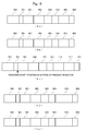
- Fig. 10-a shows the format of an Ethernet communication frame.
- the communication frame is composed of a preamble 500 (7 bytes), an SFD 501 (Start Frame Delimiter, 1 byte), a destination address 601 (6 bytes), a source address 602 (6 bytes), a type 603 (2 bytes), data 620 (46 to 1500 bytes), and an FCS 606 (Flame Check Sequence, 4 bytes), and the minimum frame length is 64 bytes, from the destination address 601 to the FCS 606.
- a communication frame is transferred after the end thereof has been received.
- a transfer delay time of at least 5.2 ⁇ s which is required for receiving the SFD (1 byte) and the minimum frame length of 64 bytes, occurs in a communication device.
- Some switching HUBs implement Cut-through as another transfer mode for reducing this transfer delay time. Cut-through is a transfer method in which a transfer to the port to the destination device is connected is started at a timing when the destination address 601 is received. Even in this method, however, a transfer delay time of 560 ns, which is required for receiving the SFD (1 byte) and the destination address (6 bytes), occurs in a communication device.
- An Ethernet communication system in the OA field generally has a configuration in which communication devices are connected in parallel with a HUB therebetween.
- devices are often connected in series to a transmission path in order to save wiring.
- a tendency has been to apply the Ethernet technology in the industrial fields.
- the transfer delay time of a relay communication device affects performance.
- Fig. 11-a is a configuration diagram of a conventional system in which communication devices that perform relaying by Cut-through described above are connected in series.
- reference numeral 1101 denotes a first communication device that manages a reference time
- reference numerals 1102 and 1103 denote second communication devices #1 and #2 that operate in synchronization with the communication device 1101.
- the first communication device corresponds to, for example, a programmable controller or a personal computer
- the second communication devices correspond to, for example, servo drives, sensors, relays, or the like.
- a port 1 (1150) of the first communication device and a port 1 (1151) of the second communication device #1 are connected in series
- a port 2 (1152) of the second communication device #1 and a port 1 (1153) of the second communication device #2 are connected in series.
- the second communication device #1 relays the communication data. For example, when data is sent from the first communication device to the second communication device #2, the data sent by the first communication device passes through the second communication device #1 from the port 1 (1151) and is output from the port 2 (1152). Thereafter, the data is received by the second communication device #2 via the port 1 (1153).
- Fig. 11-b is an exemplary timing chart showing timings of communication and synchronous operations in a conventional system.
- symbol S denotes a synchronization frame that is broadcast by the communication device 1101 at the beginning of a communication cycle in order to perform communication synchronization across the entire system.
- symbol CMD #1 denotes a command frame sent from the communication device 1101 to the communication device 1102
- symbol RSP #1 denotes a response frame sent from the communication device 1102 to the communication device 1101.
- the command frame is used for notification about relay ON/OFF or a target position of a servo drive
- the response frame is used for notification about a current value of a sensor or a position feedback value of a servo drive.
- Symbols CMD #2 and RSP #2 are a command frame and a response frame to and from the communication device 1103, respectively, and have content equivalent to the CMD #1 and the RSP #1.
- the propagation delay time in the transmission path between the second communication device #n and the previous communication device is represented by Ttr_n
- the transfer delay time in the relay communication device is represented by Trpt
- the second communication devices #1 and #2 perform a synchronous operation by causing a communication synchronization interrupt at the timing of receiving the synchronization frame S sent from the first communication device.
- each return delay time (the time required for data to reciprocate) with a communication device that manages a reference time is determined and in which a delay time to each communication device is measured on the assumption that the time required for outgoing communication and the time required for incoming communication are equal.
- Fig. 9 shows an example of a conventional communication system referenced in Patent Document 2.
- n communication devices 1001 to 1005 are connected in series to a transmission path 1012.
- the first communication device 1001 sends data for measurement to the second communication device 1002 twice, and the second communication device 1002 returns this measurement data at the input end and output end, thereby measuring a propagation delay time Tab ( ⁇ Tba) and an in-device transfer delay time TB1 ( ⁇ TB2).
- the first communication device sends the measurement data to the third communication device 1003, and measures delay times Tbc ( ⁇ Tcb) and TC1 ( ⁇ TC2).
- the first communication device 1001 measures delay times for up to the n-th communication device 1005 and then notifies each communication device of the delay time.
- Each communication device corrects its clock time using the delay time notified by the first communication device 1001, and synchronizes the clock time to the reference time.
- a difference between the delay time for the outgoing communication and the delay time for the incoming communication causes an error in the delay time.
- the above-described transmission path delay time also occurs when the first communication device sends a command frame to the second communication device #n or when the second communication device #n sends a response frame to the first communication device, resulting in an unnecessary lag time, which is twice the time given in the equation above, in the response time occurring when the first communication device exchanges the command frame and the response frame with the second communication device #n.
- a lag time of 10.08 ⁇ s is caused only in the transfer delay time in the tenth communication device. Therefore, in all the ten second communication devices, a total lag time of 50.4 ⁇ s is caused only in the transfer delay times.
- the communication cycle which is on the order of 100 ⁇ s is performed, this occupies the majority of the communication cycle. Consequently, the communication cycle cannot be reduced, and the performance of motion control cannot be improved even with the use of high-speed communication.
- the present invention has been made in view of such problems, and it is an object of the present invention to provide a communication device, a synchronized communication system, and a synchronized communication method in which even when communication devices are connected in series to a transmission path, delay times are measured and a reference time of each slave is corrected so that the control cycle start timing is specified and synchronized on a reference time basis and in which the transfer delays of the communication devices can be reduced to realize synchronized communication with as small a communication cycle as possible.
- the invention according to Claim 1 provides a communication device including a communication control section that is connected to a transmission path and that controls data to be sent and received, and a host CPU that is connected to the communication control section and that executes a calculation process based on data received by the communication control section and data in a built-in connected-device information storage section to create transmission data and sends the transmission data to the communication control section, wherein the communication control section includes two PHY sections each of which converts a logic signal into an electrical signal, two Rx FIFO sections (reception first-in first-out sections) that are connected to the PHY sections and that receive data received by the PHY sections, two Tx FIFO sections (transmission first-in first-out sections) that are connected to the PHY sections and that output the received data to the PHY sections, and a LINK section having a built-in in-device reference timer that generates an interrupt signal at a preset timing, wherein each of the two Rx FIFO sections (reception first-in first-out sections) that
- the invention according to Claim 2 provides a communication device including a communication control section that is connected to a transmission path and that controls data to be sent and received, and a host CPU that is connected to the communication control section and that executes a calculation process based on data received by the communication control section and data in a built-in local information storage section to create transmission data and sends the transmission data to the communication control section
- the communication control section includes two PHY sections each of which converts a logic signal into an electrical signal, two Rx FIFO sections (reception first-in first-out sections) that are connected to the PHY sections and that receive data received by the PHY sections, two Tx FIFO sections (transmission first-in first-out sections) that are connected to the PHY sections and that output the received data to the PHY sections, and a LINK section having a built-in in-device reference timer that generates an interrupt signal at a preset timing, wherein each of the two Rx FIFO sections and each of the two Tx FIFO sections are connected via
- each of the Rx FIFO sections includes an SFD (frame start signal) detection section disposed upstream thereof, and upon detection of an SFD that follows a preamble in data received by one of the PHY sections, a corresponding one of the SFD detection sections immediately transfers the received data to the transmission path from the other PHY section.
- SFD frame start signal
- each of the Rx FIFO section includes an SFD (frame start signal) detection section disposed upstream thereof, and upon detection of an SFD that follows a preamble in data received by one of the PHY sections, a corresponding one of the SFD detection sections immediately transfers the received data to the transmission path from the other PHY section.
- SFD frame start signal
- the invention according to Claim 5 provides a synchronized communication system including a first communication device according to Claim 1 or 3, and one or more second communication devices according to Claim 2 or 4, the first communication device and the second communication devices performing communication in a predetermined communication cycle, wherein one of two PHY sections of each communication device is connected to a PHY section of another communication device, and the other PHY section is connected to a PHY section of another communication device, wherein the first communication device separately measures transmission path delay times to the second communication devices, separately notifies the devices of the transmission path delay times, and sends a current reference time value in the communication system for each communication cycle, and wherein each of the second communication devices corrects the received current reference time value using the notified transmission path delay time, and sets the corrected value in its in-device reference timer.
- the invention according to Claim 6 provides the synchronized communication system according to Claim 5, wherein the first communication device stores an interrupt output time in the synchronization frame and sends the synchronization frame to the second communication devices, and each of the second communication devices sets the received interrupt output time in its in-device reference timer and outputs a synchronization interrupt signal when a value of the timer has reached the interrupt output time.
- the invention according to Claim 7 provides the synchronized communication system according to Claim 5 or 6, wherein after the first communication device starts synchronized communication with a constant communication cycle including sending a synchronization frame and a command frame to the second communication devices and receiving response frames from the second communication devices, when the first communication device detects the second communication device that has been newly connected to the synchronized communication system during the synchronized communication with the second communication devices, the first communication device measures a transmission path delay time to the second communication device and notifies the second communication device of the transmission path delay time within a time that remains after predetermined communication has been performed in the communication cycle.
- the invention according to Claim 8 provides a synchronized communication method in which in a communication system in which one first communication device and one or more second communication devices are connected to a transmission path, each communication device including a communication control section that controls transmission/reception data and a host CPU section that executes a calculation process based on data received by the communication control section to create transmission data, the communication devices perform synchronized communication, the method including the steps of specifying a synchronization-correction-target communication device in accordance with information about the second communication devices that is stored in advance in a connected-device information storage section; sending a transmission path delay measurement frame to the synchronization-correction-target communication device and at the same time storing a sending time; in a case of receiving return data from the synchronization-correction-target communication device, storing a receiving time, and in a case of receiving no return data, additionally writing delay measurement failure into the connected-device information storage section; calculating a transmission path delay time from the sending time and the receiving time and additionally writing the transmission path
- the invention according to Claim 9 provides the synchronized communication method according to Claim 8, further including the steps of, during the synchronized communication, after the first communication device performs predetermined communication including sending a synchronization frame and a command frame to the second communication devices and receiving response frames from the second communication devices:
- the invention according to Claim 10 provides the synchronized communication method according to Claim 9, wherein the transmission path delay measurement time is calculated using a maximum value of transmission path delay times stored in the connected-device information storage section, the number of times the delay measurement is performed, and a relay time in a communication device determined by circuit configuration.
- the invention according to Claim 11 provides the synchronized communication method according to Claim 8 or 9, wherein each of the second communication devices, when specified as a synchronization-correction-target communication device by the first communication device, performs the steps of setting a path selection switch so as to return received data to a source of the received data, connecting the path selection switch to a relay destination in a case where the second communication device has received the transmission delay measurement frame from the first communication device and has been notified of a transmission path delay time, and correcting an in-device reference timer using the transmission path delay time and a reference time contained in a synchronization frame sent from the first communication device, thereby performing synchronization between the reference time and the in-device reference timer.
- the invention according to Claim 12 provides the synchronized communication method according to Claim 8 or 9, wherein each of the second communication devices stores a number of times delay measurement is performed, the number of times being contained in the synchronization-correction-target specifying frame, connects the path selection switch to a delay destination after receiving a transmission path delay measurement frame the number of times of delay measurement + 1 times, upon receipt of a transmission path delay measurement frame, stores a transmission path delay time contained in the transmission path delay measurement frame, and corrects an in-device reference timer using the transmission path delay time and a current reference time value contained in a subsequently received synchronization frame.
- a path selection switch is mounted in a relay path in a second communication device.
- a first communication device can only control this switching switch to easily and accurately measure a transmission path delay time for each second communication device, and can notify each second communication device of the measurement result and a reference time of a synchronized communication system. Then, the second communication device corrects its reference time using the transmission path delay time and the reference time. Therefore, a reference time synchronized with the reference time of the first communication device can be utilized.
- each of the second communication devices can generate an interrupt signal at a preset timing. Therefore, devices connected to all the second communication devices can start processes for command data included in command frames at the same timing.
- a second communication device that has been newly connected during synchronized communication by a communication system at a constant communication cycle can be notified of a transmission path delay time measured by the first communication device without disturbing the communication cycle of the synchronized communication.
- the second communication device can perform synchronized communication.
- the first communication device can estimate a time required for measuring a transmission path delay time for a newly connected second communication device.
- the first communication device can measure a transmission path delay time for each of the second communication devices a plurality of times, and can more accurately obtain a transmission path delay time.
- SFD detection sections are provided upstream of two Rx FIFO sections provided in each communication device, and no monitoring of data subsequent to the frame start signal of the received data is performed in the relay paths.
- data can be passed to the relay paths only when the correct SFD that follows the preamble has been detected.
- unnecessary relaying of erroneous data is eliminated and only necessary data can be relayed at a higher speed. Consequently, the transfer delay time required when, for example, ten communication devices are connected in series can be reduced from 50.4 ⁇ s to 7.2 ⁇ s as compared with the conventional Cut-through scheme.
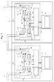
- Fig. 1 is a block diagram showing the configuration of communication devices of the present invention.
- a first communication device 1 and a second communication device 2 are connected in series using a transmission path 5.
- the first communication device 1 includes an in-device reference timer 141, which is disposed in a LINK section 140, for managing a reference time of the communication system
- the second communication device 2 includes an in-device reference timer 241, which is disposed in a LINK section 240, for performing synchronization with the reference time of the communication system.
- the reference time is used as a basis for the synchronized communication system to start its operation and the like.
- the reference time is contained in a synchronization frame at the beginning of each communication cycle, and is sent to each second communication device from the first communication device.
- each second communication device decrements its reference time, and outputs an interrupt signal when the value of the reference time becomes a preset interrupt output time.
- the synchronized communication system can allow all the devices to start processes at the same timing. While in the present example, an in-device reference timer is mounted inside a LINK section, a dedicated timer may be mounted outside a LINK section.
- the first communication device 1 includes a communication control section 100 that controls transmission/reception data, and a host CPU section 10 that executes a calculation process based on data received by the communication control section 100 to create transmission data.
- the host CPU section 10 includes a connected-device information storage section 11 that stores information about other communication devices connected to the transmission path.
- the communication control section 100 includes PHY sections (also referred to as first layers or physical layers) 110 that are connected to the transmission path and that convert a logic signal into an electrical signal in order to deliver data to the transmission path, a LINK section 140 that performs data transmission/reception with the PHY sections 110, Rx FIFO sections 130 that hold data received by the PHY sections 110, and Tx FIFO sections 120 that hold transmission data from the LINK section 140 and the Rx FIFO sections 130.
- the two PHY sections 110, the two Rx FIFO sections 130, and the two Tx FIFO sections 120 constitute two relay paths 160 over which data received by one of the PHY sections 110 is transferred to the other PHY section 110.
- the relay paths 160 allow data received by one of the PHY sections 110 to be directly transferred to another communication device from the other PHY section.
- SFD detection sections 115 are provided between the PHY sections 110 and the Rx FIFO sections 130, and monitor the SFD that follows the preamble of received data.
- the SFD is a 1-byte frame start flag, which is expressed as '5D' in hexadecimal.
- each of the SFD detection sections 115 Upon correct detection of the SFD, each of the SFD detection sections 115 immediately outputs a reception signal 116 output from the PHY section 110 to the other PHY section 110 as a transfer permission signal 117 through the Rx FIFO 130 and the Tx FIFO 120, and also transfers the received data to the Tx FIFO 120 through the Rx FIFO 130.
- the PHY section 110 Upon receipt of this transfer permission signal, the PHY section 110 immediately transfers the reception data, which has been transferred from the Tx FIFO 120, to the transmission path 5. This transfer permission signal and the reception data are not output to the Rx FIFO 130 when the transfer of the current frame is completed or when the current frame is interrupted due to a transmission error or the like.
- the transfer of received data from the PHY sections 110 to the transmission path 5 is kept stopped until the next time the SFD is correctly detected.
- the PHY sections are not limited to those configured to perform conversion between a logic signal and an electrical signal, but may be configured to perform conversion between a logic signal and an optical signal or perform conversion between a logic signal and a radio signal.
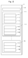
- Fig. 2 shows an example configuration of the connected-device information storage section 11 of the first communication device 1 shown in Fig. 1 .
- the connected-device information storage section 11 includes a connectable-number storage area 1110 that stores a number (in Fig. 2 , n) representing the number of one or more connectable second communication devices #1, #2, ... #n that are connected to the first communication device 1, and second-communication-device information storage sections 111, 112, ... 11n that store information about the number n of connectable second communication devices.
- the information storage section 111, 112, ... 11n further include address storage areas 1111, 1121, ... 11n1 for the individual communication devices, transmission-path delay measurement completion/failure information storage areas 1112, 1122, ...
- the number of connectable second communication devices is the number of second communication devices necessary for an application system to be realized, and is written in advance in the connectable-number storage area 1110 using an engineering tool or the like (not shown).
- the addresses for specifying the second communication devices are also written in advance in the address storage areas 1111, 1121, ... 11n1.
- the second communication device 2 includes a communication control section 200 that controls transmission/reception data, and a host CPU section 20 that executes a calculation process based on data received by the communication control section 200 to create transmission data.
- the host CPU section 20 includes a local information storage section 21 that stores local information.
- the communication control section 200 includes PHY sections 210 that are connected to the transmission path and that convert a logic signal into an actual electrical signal, a LINK section 240 that performs data transmission/reception with the PHY sections 210, Rx FIFO sections 230 that hold data received by the PHY sections 210, and Tx FIFO sections 220 that hold transmission data from the LINK section 240 and the Rx FIFO sections 230.
- the two PHY sections 210, the two Rx FIFO sections 230, and the two Tx FIFO sections 220 constitute two relay paths 260 over which data received by one of the PHY sections 210 is transferred to the other PHY section 210 when path selection switches 250 are connected to the relay paths 260.
- the path selection switches 250 are connected to return paths 261 a transfer path over which data received by one of the PHY sections 210 is returned to the same PHY section 210 is formed.
- the return paths 261 are used for measuring a transmission path delay time from the first communication device to this second communication device.
- the path selection switches 250 are configured to connect the path for reception data and the path for a transfer permission signal, which will be described below, to the relay paths 260 or the return paths 261 at the same timing.
- each of the two relay paths includes one Rx FIFO 230 and one Tx FIFO 220. Also when the path selection switches 250 are connected to the return paths 261, each of the two relay paths includes one Rx FIFO 230 and one Tx FIFO 220. In either case, data to be transferred is allowed to pass through one Rx FIFO 230 and one Tx FIFO 220. Further, SFD detection sections 215 are located between the PHY sections 210 and the Rx FIFO sections 230, and monitor the SFD that follows the preamble of received data.
- each of the SFD detection sections 215 Upon correct detection of the SFD, each of the SFD detection sections 215 immediately outputs a reception signal 216 output from the PHY section 210 to the other PHY section 210 as a transfer permission signal 217 through the Rx FIFO 230 and the Tx FIFO 220, and also transfers the received data to the Tx FIFO 220 through the Rx FIFO 230.
- the PHY section 210 Upon receipt of this transfer permission signal, the PHY section 210 immediately transfers the reception data, which has been transferred from the Tx FIFO 220, to the transmission path 5. This transfer permission signal and the reception data are not output to the Rx FIFO 230 when the transfer of the current frame is completed or when the current frame is interrupted due to a transmission error or the like.
- the transfer of received data from the PHY sections 210 to the transmission path 5 is kept stopped until the next time the SFD is correctly detected.
- the second communication device 2 has the path selection switches 250 mounted therein.
- the first communication device 1 may also have the path selection switches 250 mounted therein so that both can have the same circuit configuration.
- Fig. 3 shows an example configuration of the local information storage section 21 in Fig. 1 .
- the local information storage section 21 includes a number-of-times-of-delay-measurement storage area 211 for storing the number of times of delay measurement 605 ( Fig. 8-a ) contained in a synchronization-correction-target specifying frame sent thereto, a transmission path delay time storage area 212 for storing a transmission path delay time 615 ( Fig. 8-b ) contained in a transmission path delay measurement frame, and a reference time storage area 213 that is an area for storing a current reference time value 616 ( Fig. 8-c ) contained in a synchronization frame.
- Fig. 4 shows an example of a communication system to which the present invention is applied.
- four communication devices are connected in series to a transmission path.
- a first communication device 1 manages a reference time.
- Each of second communication devices #1 to #3 (2 to 4) has a configuration similar to that shown in the block diagram of the second communication device 2 in Fig. 1 , and is synchronized with the reference time of the first communication device 1.
- the first communication device 1 is connected in such a manner that the first communication device 1 is at the end of the transmission path.
- the first communication device 1 also has a relay function mounted therein.
- the first communication device 1 may be connected in the middle of the transmission path.
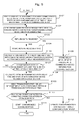
- Fig. 5 is a flowchart of the first communication device, showing a procedure for measuring a transmission path delay time of the present invention, and the procedure is executed by the host CPU 10.
- This flowchart is a diagram before the start of fixed cycle communication, and a flowchart after the start of fixed cycle communication will be described below.
- the first communication device 1 specifies one of the second communication devices #1 to #n stored in advance in the connected-device information storage section 11 (hereinafter referred to as a "target communication device"), and sends a synchronization-correction-target specifying frame ( Fig.
- step S102 a transmission path delay measurement frame ( Fig. 8-b ) is sent to the target communication device, and the time of sending the transmission path delay measurement frame is stored.
- step S104 the process proceeds to step S105 in which the delay measurement failure is stored in the connected-device information storage section 11.
- step S110 The failure of delay measurement means that, for example, a transmission path delay measurement frame has been sent to a second communication device that should be present according to the determination based on the connectable-number storage area 1110 shown in Fig.
- step S104 the return receiving time is stored.
- step S106 a transmission path delay time is calculated from the time of sending the transmission path delay measurement frame and the return receiving time, and is stored in the corresponding one of the transmission path delay time storage areas 1113 to 11n3 located in the information storage section for this target communication device in the connected-device information storage section 11.
- step S107 it is checked whether the transmission path delay measurement frame has been sent a number of times corresponding to the number of times of delay measurement. If the transmission path delay measurement frame has not been sent the required number of times, the processing of steps S102 to S106 is repeated.
- step S108 If the transmission path delay measurement frame has been sent the required number of times, in step S108, an optimum transmission path delay time such as, for example, the average value is calculated and stored in the corresponding one of the transmission path delay time storage areas 1113 to 11n3 located in the information storage section for this target communication device in the connected-device information storage section 11.
- step S109 a transmission path delay measurement frame ( Fig. 8-b ) containing the optimum transmission path delay time in the transmission path delay time 615 is sent to the target second communication device.
- step S110 it is checked whether transmission path delay measurement has been completed for a number of second communication devices corresponding to the connectable number stored in the connected-device information storage section 11.
- step S112 If the transmission path delay measurement has not been completed, in step S112, the target communication device is updated. Then, the process proceeds to step S101, and the subsequent processing of steps S101 to S110 is repeated.
- step S111 a synchronization frame ( Fig. 8-c ) is sent to all the second communication devices.
- Fig. 6 is a flowchart showing a procedure for a process performed by a second communication device in the measurement of a transmission path delay time of the present invention, and the procedure is executed by the host CPU 20.
- the second communication device 2 receives a synchronization-correction-target specifying frame sent thereto.
- the number of times of delay measurement contained in the received synchronization-correction-target specifying frame is stored in the number-of-times-of-delay-measurement storage area 211 ( Fig. 3 ) of the local information storage section 21.
- the setting to the return paths 261 ( Fig. 1 ) is performed using the path selection switches 250 ( Fig. 1 ).
- step S304 the reception of a transmission path delay measurement frame is waited.
- step S305 the transmission path delay time 615 contained in the transmission path delay measurement frame ( Fig. 8-b ) is stored in the transmission path delay time storage area 212 ( Fig. 3 ) of the local information storage section 21. Since the transmission path delay time is overwritten, the last received value is active.
- step S306 it is checked whether the transmission path delay measurement frame ( Fig. 8-b ) has been received (the number of times of delay measurement + 1) times. When the transmission path delay measurement frame has not been received (the number of times of delay measurement + 1) times, the process returns to step S304.
- step S307 When the transmission path delay measurement frame has been received (the number of times of delay measurement + 1) times, the process proceeds to step S307, and the path selection switches 250 ( Fig. 1 ) are connected to the relay paths 260 ( Fig. 1 ) so that the configuration for normal operation is set.
- step S308 the reception of a synchronization frame ( Fig. 8-c ) is waited.
- step S309 the in-device reference timer 241 ( Fig. 1 ) is corrected using the reference time contained in the received synchronization frame and the transmission path delay time. This correction is performed by, for example, as in an exemplary embodiment shown in Fig. 12 , the in-device reference timer 241 is updated to a value obtained by subtracting the transmission path delay time from the reference time. Also, when this in-device reference timer is an up counter, an update to a value obtained by adding the transmission path delay time to the reference time is made.
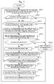
- Fig. 7 shows a procedure for measuring a transmission path delay time when a new second communication device 2 ( Fig. 1 ) is connected in a case where the first communication device 1 ( Fig. 1 ) starts synchronized communication in a constant communication cycle in a state where a number of second communication devices corresponding to the connectable number 1110 ( Fig. 2 ) in the connection information storage section 11 are not connected.
- the process based on this procedure is executed by the host CPU 10.
- the term synchronized communication is communication that is performed in a predetermined constant communication cycle between a first communication device and second communication devices after the first communication device sets a transmission path delay time in each of the second communication devices and sends a synchronization frame once.
- the first communication device performs communication in a constant communication cycle, such as sending a synchronization frame to each second communication device, sending a command frame, and receiving a response frame from each second communication device.
- step S201 the first communication device 1 starts synchronized communication with all the second communication devices #1 to #n ( Fig. 2 ) (the number of which corresponds to that stored in the connectable number 1110) stored in the connected-device information storage section 11.
- step S202 it is checked whether a response has been received from any of the second communication devices for which delay measurement failure has been recorded in the connected-device information storage section 11. If no response has been received, the process proceeds to step S208 in which the end of the communication cycle is waited. Then, the process proceeds to step S201. If a response has been received, the process proceeds to step S203 in which the remaining time of the communication cycle is compared with the time required for transmission path delay measurement to check whether the transmission path delay measurement can be completed within the remaining time of the communication cycle.
- the transmission path delay measurement time has a value that is determined by the equation given in Eq. 1 using a maximum value Tmax_dly of the transmission path delay times stored in the connected-device information storage section 11 (the transmission path delay time to the second communication device that is the most far from the first communication device), the number of times Ncnt delay measurement is performed, and a relay time Trpt in a communication device determined by circuit configuration. 2 ⁇ Tmax_dly + Trpt ⁇ Ncnt + 1 + ⁇ Note that Eq. 1 is used for a new second communication device connected to a second communication device for which the measurement of transmission path delay time has already been completed and that is connected at the most far position from the first communication device.
- ⁇ denotes the time that is required for the process in the flowchart shown in Fig. 7 in the first communication device and that does not result from Tmax_dly or Trpt, which means, for example, the time required for calculating the average value or the like.
- step S208 When it is determined in S203 that the transmission path delay measurement cannot be completed, the process proceeds to step S208.
- the process proceeds to step S204.
- a synchronization-correction-target specifying frame ( Fig. 8-a ) containing the number of times of delay measurement 605 is sent to a second communication device from which a response has been received and for which delay measurement failure has been recorded (hereinafter referred to as a "target communication device").
- a transmission path delay measurement frame Fig.
- step S206 when the transmission path delay measurement frame returned from the target communication device is received in step S206, the process proceeds to step S207. Otherwise, the process proceeds to step S208.
- step S207 When the transmission path delay measurement frame returned from the target communication device has been received, in step S207, the time of receiving the returned data is stored. Then, in step S209, a transmission path delay time is calculated from the time of sending the transmission path delay measurement frame and the time of receiving the returned data, and is stored in the corresponding one of the transmission path delay time storage areas 1113 to 11n3 located in the information storage section for this target communication device in the connected-device information storage section 11.
- the method for calculating a transmission path delay time is similar to that in the case of Fig. 5 .
- step S210 it is checked whether the transmission path delay measurement frame has been sent a number of times corresponding to the number of times of delay measurement. If the transmission path delay measurement frame has not been sent the required number of times, the processing of steps S205 to S209 is repeated. If the transmission path delay measurement frame has been sent the required number of times, in step S211, an optimum transmission path delay time such as, for example, the average value is calculated and stored in the corresponding one of the transmission path delay time storage areas 1113 to 11n3 located in the information storage section for this target communication device in the connected-device information storage section 11. In step S212, a transmission path delay measurement frame ( Fig.
- step S213 the end of the communication cycle is waited. Then, the process returns to step S201. The above steps are repeated. Note that if it is checked in step S202 whether or not response data included in the received response frame is response data from a second communication device for which consecutive synchronized communication errors have occurred, a transmission path delay time for a second communication device that is disconnected and reconnected during synchronized communication can also be measured using a procedure similar to that shown in Fig. 7 .
- Fig. 8 shows an example of a synchronization-correction-target specifying frame ( Fig. 8-a ), a transmission path delay measurement frame ( Fig. 8-b ), a synchronization frame ( Fig. 8-c ), a command frame ( Fig. 8-d ), and a response frame ( Fig. 8-e ) which are sent or received by the first communication device 1 ( Fig. 1 ).
- the five pieces of data commonly have, in addition to a preamble 500, an SFD (Start Frame Delimiter) 501, a destination address 601, a source address 602, a data type 603, and a data length 604, an FCS (Flame Check Sequence) 606 for detecting an error of transmission data.
- the five pieces of data are identified using the data type 603. Note that data is not limited to these five types, and a frame having a different configuration can be added, as necessary, in accordance with necessity such as an application.
- Fig. 8-a shows an example of a synchronization-correction-target specifying frame which is sent from the first communication device to a second communication device for which the delay time is to be measured (synchronization-correction-target communication device).
- the destination address 601 contains addresses unique to synchronization-correction-target communication devices.
- the addresses are stored in the information storage sections 111 to 11n ( Fig. 2 ) for the second communication devices 1 to n in the connected-device information storage section 11.
- Fig. 8-b shows an example of a transmission path delay measurement frame which is sent from the first communication device to a synchronization-correction-target communication device.
- a transmission path delay time 615 contains 0 at the time of the first transmission and contains a result of the (m-1)-th measurement at the time of the m-th transmission before the transmission path delay measurement frame is sent to the synchronization-correction-target communication device.
- the first communication device calculates an optimum transmission path delay time such as a maximum value of these measurement results, the average value, or a value obtained by adding an extra time to the average value, and contains the optimum transmission path delay time in the transmission path delay time 615.
- the resulting transmission path delay measurement frame is sent to the synchronization-correction-target communication device.
- a current reference time value 616 contains the value of the in-device reference timer 141 ( Fig. 1 ) that is obtained when a synchronization frame is sent.
- An interrupt output time 617 is used for setting a timing at which each second communication device outputs an interrupt signal to the host CPU 20 ( Fig. 1 ), and is written by the host CPU 10 ( Fig. 1 ) through the LINK 140 ( Fig. 1 ).
- the interrupt output time is set to, for example, a timing at which the second communication device that is the most far from the first communication device receives a command frame and starts a process for command data included in the command frame.
- the interrupt output time may be set to a timing at which the second communication device that last received a command frame sent from the first communication device to all second communication devices can start a process for command data included in the command frame.
- Fig. 8-d shows a command frame which is sent from the first communication device to a second communication device.
- the second communication device starts a process for command data 618 in synchronization with an interrupt signal output at the interrupt output time.
- Fig. 8-e shows a response frame which is received by the first communication device from a second communication device.
- the second communication device sends this response frame after receiving a command frame from the first communication device.
- Fig. 12 shows an example showing the synchronization between the in-device reference timers 141 and 241 ( Fig. 1 ) incorporated respectively in the first communication device and one or more second communication devices that constitute a communication system.
- the second communication device #1 first receives this frame.
- the second communication device #1 updates the in-device reference timer 241 using a value obtained by subtracting a transmission path delay time Tdly_1 from the first communication device to the second communication device #1, which is measured in advance, from the current reference time value 616 ( Fig.
- the second communication device #2 also updates the in-device reference timer 241 using a transmission path delay time Tdly_2 from the first communication device 1 to the second communication device #2, which is measured in advance, and the current reference time value 616. Accordingly, the in-device reference timer 141 in the first communication device and the in-device reference timers 241 in the second communication devices #1 and #2 are timed.
- an interrupt signal is output when a match occurs between the value of the interrupt output time 617 contained in the synchronization frame and the values of the in-device reference timers 241 in the second communication devices #1 and #2.
- each communication device can output an interrupt for each communication synchronization to a host CPU at the same time. Note that although an in-device reference timer of each communication device operates based on a separate clock (not shown), the difference in frequency between the individual clocks may be negligible because it is much smaller than that between the reference times corrected in each communication cycle.
- the process for command data given in the same communication cycle can be started at the same interrupt timing.
- the communication cycle can be reduced. Therefore, a contribution to improvement of control performance of a motion control system including a plurality of servo amplifiers, relays, sensors, and the like as second communication devices can be made.
Abstract
Description
- The present invention relates to a synchronized communication method in which all communication devices connected to a transmission path are synchronized with a reference time in a communication system, a communication device used therefor, and a synchronized communication system therefor.
- In manufacturing systems, generally, a single control device such as a programmable controller or a personal computer periodically exchanges command data and response data with a plurality of devices such as sensors, relays, and servo drives to perform control. Each device is connected to a transmission path, and the exchange of command data and response data is performed in constant communication cycles through communication. In particular, in motion control systems for machine tools, chip mounters, and the like, a motion controller forms a control loop together with servo drives through a transmission path.
Therefore, a synchronized communication system in which the exchange of command data and response data can be realized in steady communication cycles is demanded to allow these devices to operate in synchronization with the communication cycles. In order to achieve such enhancement in performance of motion control, it is necessary to synchronize the timings of starting the processing of command data received by the servo drives and the like from the motion controller so that the amount of synchronization deviation thereof can be minimized and it is also necessary to shorten as much as possible the communication cycle in which the motion controller and the servo drives exchange command data and response data. - Conventionally, in order to synchronize all communication devices connected to a transmission path with a reference time in a communication system, a method has been adopted in which a communication device that manages the reference time informs one or more other communication devices of the reference time.
For example, in a case where three communication devices are connected in parallel to a transmission path and among them one communication device (first communication device) manages a reference time, a method has been adopted in which the first communication device sends the reference time to the remaining two communication devices (a secondcommunication device # 1 and a second communication device #2) via broadcasting so that the two second communication devices can receive it and adjust in-device reference timers.
In this case, the times at which the two second communication devices receive the data sent by the first communication device are different. This is because a time (propagation delay time) is required for a signal to propagate along the transmission path, resulting in the occurrence of a difference between the arrival times depending on the length of the transmission path.
However, the difference in the propagation delay time between the communication devices has a very small value.
In such a communication system, the first communication device broadcasts communication data at the beginning of a communication cycle, and all the second communication devices that have received it operate in synchronization with the receiving timings, which is sufficient to realize a synchronized communication system with a small amount of synchronization deviation between the communication devices. - Incidentally, in the OA field, Ethernet (registered trademark), which adopts a 100 BASE-T or 1000 BASE-T physical layer, has been widespread as means for connecting personal computers, printers, and the like to perform high-speed communication. In a communication system based on Ethernet, devices are generally connected point-to-point. Devices such as personal computers and printers are connected to a HUB, and the HUB serves as a relay station to perform a transfer when data is sent and received between communication devices.
A HUB serving as a relay station is generally implemented as a switching HUB having a switching function as shown inPatent Document 1 inFig. 10-b , and Store & Forward is adopted as a general transfer mode. Store & Forward uses a procedure for storing all units in a communication frame, starting from the beginning to the end, in a buffer, performing an error check, and transferring a unit that shows a normal result to a port to which a destination device is connected. -
Fig. 10-a shows the format of an Ethernet communication frame. The communication frame is composed of a preamble 500 (7 bytes), an SFD 501 (Start Frame Delimiter, 1 byte), a destination address 601 (6 bytes), a source address 602 (6 bytes), a type 603 (2 bytes), data 620 (46 to 1500 bytes), and an FCS 606 (Flame Check Sequence, 4 bytes), and the minimum frame length is 64 bytes, from thedestination address 601 to the FCS 606.
As described previously, in Store & Forward, a communication frame is transferred after the end thereof has been received. Thus, in the case of a transmission speed of 100 Mbps, a transfer delay time of at least 5.2 µs, which is required for receiving the SFD (1 byte) and the minimum frame length of 64 bytes, occurs in a communication device.
Some switching HUBs implement Cut-through as another transfer mode for reducing this transfer delay time. Cut-through is a transfer method in which a transfer to the port to the destination device is connected is started at a timing when thedestination address 601 is received. Even in this method, however, a transfer delay time of 560 ns, which is required for receiving the SFD (1 byte) and the destination address (6 bytes), occurs in a communication device. - An Ethernet communication system in the OA field generally has a configuration in which communication devices are connected in parallel with a HUB therebetween. In industrial fields such as on a production line, however, devices are often connected in series to a transmission path in order to save wiring. In recent years, due to the feature of improved transmission speed, a tendency has been to apply the Ethernet technology in the industrial fields. However, in a case where communication devices are connected in series to a transmission path, the transfer delay time of a relay communication device affects performance.
-
Fig. 11-a is a configuration diagram of a conventional system in which communication devices that perform relaying by Cut-through described above are connected in series. In the figure,reference numeral 1101 denotes a first communication device that manages a reference time,reference numerals communication devices # 1 and #2 that operate in synchronization with thecommunication device 1101. In the case of a manufacturing system, the first communication device corresponds to, for example, a programmable controller or a personal computer, and the second communication devices correspond to, for example, servo drives, sensors, relays, or the like.
Here, a port 1 (1150) of the first communication device and a port 1 (1151) of the secondcommunication device # 1 are connected in series, and a port 2 (1152) of the secondcommunication device # 1 and a port 1 (1153) of the secondcommunication device # 2 are connected in series. When the first communication device and the secondcommunication device # 2 exchange communication data, the secondcommunication device # 1 relays the communication data. For example, when data is sent from the first communication device to the secondcommunication device # 2, the data sent by the first communication device passes through the secondcommunication device # 1 from the port 1 (1151) and is output from the port 2 (1152). Thereafter, the data is received by the secondcommunication device # 2 via the port 1 (1153). -
Fig. 11-b is an exemplary timing chart showing timings of communication and synchronous operations in a conventional system. In the figure, symbol S denotes a synchronization frame that is broadcast by thecommunication device 1101 at the beginning of a communication cycle in order to perform communication synchronization across the entire system.Symbol CMD # 1 denotes a command frame sent from thecommunication device 1101 to thecommunication device 1102, andsymbol RSP # 1 denotes a response frame sent from thecommunication device 1102 to thecommunication device 1101. The command frame is used for notification about relay ON/OFF or a target position of a servo drive, and the response frame is used for notification about a current value of a sensor or a position feedback value of a servo drive.Symbols CMD # 2 andRSP # 2 are a command frame and a response frame to and from thecommunication device 1103, respectively, and have content equivalent to theCMD # 1 and theRSP # 1. - Next, a control start timing will be explained. It is assumed that the propagation delay time in the transmission path between the second communication device #n and the previous communication device is represented by Ttr_n, the transfer delay time in the relay communication device is represented by Trpt, and the second
communication devices # 1 and #2 perform a synchronous operation by causing a communication synchronization interrupt at the timing of receiving the synchronization frame S sent from the first communication device. In this case, due to the propagation delay in the transmission path and the transfer delay, there is a time difference of (Trpt + Ttr_2) between the timings of causing a communication synchronization interrupt by the secondcommunication devices # 1 and #2.
Here, if the sum of the transfer delay time in a communication device and the propagation delay time of the transmission path is called a transmission path delay time, the transmission path delay time #n required until the synchronization frame S sent by the first communication device is received by the second communication device #n is expressed by the equation below. Here, it is assumed that Trpt has the same value for all the communication devices.
Transmission path delay time #n:
Thus, in order to allow a plurality of second communication devices or devices connected to the second communication devices to operate synchronously, a reference time held by each second communication device must have been obtained by correcting a reference time held by the first communication device using the transmission path delay time. - As an example for measuring a transmission path delay time, there is a method in which each return delay time (the time required for data to reciprocate) with a communication device that manages a reference time is determined and in which a delay time to each communication device is measured on the assumption that the time required for outgoing communication and the time required for incoming communication are equal.
-
Fig. 9 shows an example of a conventional communication system referenced inPatent Document 2. InFig. 9 ,n communication devices 1001 to 1005 are connected in series to atransmission path 1012. In this configuration, in order to synchronize the clock times of the individual communication devices, first, thefirst communication device 1001 sends data for measurement to thesecond communication device 1002 twice, and thesecond communication device 1002 returns this measurement data at the input end and output end, thereby measuring a propagation delay time Tab (≡ Tba) and an in-device transfer delay time TB1 (≡ TB2).
Thereafter, similarly, the first communication device sends the measurement data to thethird communication device 1003, and measures delay times Tbc (≡ Tcb) and TC1 (≡ TC2). Likewise, thefirst communication device 1001 measures delay times for up to the n-th communication device 1005 and then notifies each communication device of the delay time. Each communication device corrects its clock time using the delay time notified by thefirst communication device 1001, and synchronizes the clock time to the reference time.
In the communication system as shown inFig. 9 , however, since the outgoing and incoming communications pass through different internal memories in the communication devices, a difference between the delay time for the outgoing communication and the delay time for the incoming communication causes an error in the delay time. - In addition, the above-described transmission path delay time also occurs when the first communication device sends a command frame to the second communication device #n or when the second communication device #n sends a response frame to the first communication device, resulting in an unnecessary lag time, which is twice the time given in the equation above, in the response time occurring when the first communication device exchanges the command frame and the response frame with the second communication device #n.
For example, in the case of a communication system in which ten second communication devices are connected, a lag time of 10.08 µs is caused only in the transfer delay time in the tenth communication device. Therefore, in all the ten second communication devices, a total lag time of 50.4 µs is caused only in the transfer delay times. When the communication cycle which is on the order of 100 µs is performed, this occupies the majority of the communication cycle. Consequently, the communication cycle cannot be reduced, and the performance of motion control cannot be improved even with the use of high-speed communication. - [Patent Document 1] Japanese Unexamined Patent Application Publication (Translation of PCT Application) No.
2000-503828 Fig. 4 ) - [Patent Document 2] Japanese Unexamined Patent Application Publication No.
10-142361 Fig. 4 ) - The present invention has been made in view of such problems, and it is an object of the present invention to provide a communication device, a synchronized communication system, and a synchronized communication method in which even when communication devices are connected in series to a transmission path, delay times are measured and a reference time of each slave is corrected so that the control cycle start timing is specified and synchronized on a reference time basis and in which the transfer delays of the communication devices can be reduced to realize synchronized communication with as small a communication cycle as possible.
- In order to overcome the foregoing problems, the present invention is configured as follows.
The invention according toClaim 1 provides a communication device including a communication control section that is connected to a transmission path and that controls data to be sent and received, and a host CPU that is connected to the communication control section and that executes a calculation process based on data received by the communication control section and data in a built-in connected-device information storage section to create transmission data and sends the transmission data to the communication control section,
wherein the communication control section includes two PHY sections each of which converts a logic signal into an electrical signal, two Rx FIFO sections (reception first-in first-out sections) that are connected to the PHY sections and that receive data received by the PHY sections, two Tx FIFO sections (transmission first-in first-out sections) that are connected to the PHY sections and that output the received data to the PHY sections, and a LINK section having a built-in in-device reference timer that generates an interrupt signal at a preset timing,
wherein each of the two Rx FIFO sections and each of the two Tx FIFO sections are connected via a relay path, and the two relay paths and the LINK section are connected to each other, and
wherein the LINK section sends a synchronization-correction-target specifying frame, a transmission path delay measurement frame, and a synchronization frame. - Further, the invention according to
Claim 2 provides a communication device including a communication control section that is connected to a transmission path and that controls data to be sent and received, and a host CPU that is connected to the communication control section and that executes a calculation process based on data received by the communication control section and data in a built-in local information storage section to create transmission data and sends the transmission data to the communication control section,
wherein the communication control section includes two PHY sections each of which converts a logic signal into an electrical signal, two Rx FIFO sections (reception first-in first-out sections) that are connected to the PHY sections and that receive data received by the PHY sections, two Tx FIFO sections (transmission first-in first-out sections) that are connected to the PHY sections and that output the received data to the PHY sections, and a LINK section having a built-in in-device reference timer that generates an interrupt signal at a preset timing,
wherein each of the two Rx FIFO sections and each of the two Tx FIFO sections are connected via a relay path, and the two relay paths and the LINK section are connected to each other, wherein a path selection switch is inserted into each of the two relay paths, and one of a return path is connected to each of the two relay paths, the path selection switch being connected to the other end of the return path when the path selection switch disconnects the corresponding one of the relay paths, operations of the two path selection switches being performed at the same time,
wherein in a normal state, the LINK section forms a relay path over which the path selection switches are not caused to perform a switching operation and over which data received by one of the PHY sections is transferred to the other PHY section, but upon receipt of a synchronization-correction-target specifying frame, the LINK section forms a return path over which the path selection switches are caused to perform a switching operation to return data received by the PHY sections,
wherein upon receipt of a transmission path delay measurement frame a predetermined number of times after receiving the synchronization-correction-target specifying frame, the LINK section forms the relay path again using the path selection switches, and
wherein upon receipt of the synchronization frame sent from the communication device according toClaim 1, the in-device reference timer is corrected so as to be synchronized with a reference time in a communication system. - Further, the invention according to
Claim 3 provides the communication device according toClaim 1, wherein each of the Rx FIFO sections includes an SFD (frame start signal) detection section disposed upstream thereof, and upon detection of an SFD that follows a preamble in data received by one of the PHY sections, a corresponding one of the SFD detection sections immediately transfers the received data to the transmission path from the other PHY section. - Further, the invention according to
Claim 4 provides the communication device according toClaim 2, wherein each of the Rx FIFO section includes an SFD (frame start signal) detection section disposed upstream thereof, and upon detection of an SFD that follows a preamble in data received by one of the PHY sections, a corresponding one of the SFD detection sections immediately transfers the received data to the transmission path from the other PHY section. - Further, the invention according to
Claim 5 provides a synchronized communication system including a first communication device according toClaim Claim
wherein one of two PHY sections of each communication device is connected to a PHY section of another communication device, and the other PHY section is connected to a PHY section of another communication device,
wherein the first communication device separately measures transmission path delay times to the second communication devices, separately notifies the devices of the transmission path delay times, and sends a current reference time value in the communication system for each communication cycle, and
wherein each of the second communication devices corrects the received current reference time value using the notified transmission path delay time, and sets the corrected value in its in-device reference timer. - Further, the invention according to Claim 6 provides the synchronized communication system according to
Claim 5, wherein the first communication device stores an interrupt output time in the synchronization frame and sends the synchronization frame to the second communication devices, and each of the second communication devices sets the received interrupt output time in its in-device reference timer and outputs a synchronization interrupt signal when a value of the timer has reached the interrupt output time. - Further, the invention according to Claim 7 provides the synchronized communication system according to
Claim 5 or 6, wherein after the first communication device starts synchronized communication with a constant communication cycle including sending a synchronization frame and a command frame to the second communication devices and receiving response frames from the second communication devices,
when the first communication device detects the second communication device that has been newly connected to the synchronized communication system during the synchronized communication with the second communication devices, the first communication device measures a transmission path delay time to the second communication device and notifies the second communication device of the transmission path delay time within a time that remains after predetermined communication has been performed in the communication cycle. - Further, the invention according to
Claim 8 provides a synchronized communication method in which in a communication system in which one first communication device and one or more second communication devices are connected to a transmission path, each communication device including a communication control section that controls transmission/reception data and a host CPU section that executes a calculation process based on data received by the communication control section to create transmission data, the communication devices perform synchronized communication,
the method including the steps of specifying a synchronization-correction-target communication device in accordance with information about the second communication devices that is stored in advance in a connected-device information storage section; sending a transmission path delay measurement frame to the synchronization-correction-target communication device and at the same time storing a sending time; in a case of receiving return data from the synchronization-correction-target communication device, storing a receiving time, and in a case of receiving no return data, additionally writing delay measurement failure into the connected-device information storage section; calculating a transmission path delay time from the sending time and the receiving time and additionally writing the transmission path delay time into the connected-device information storage section; and notifying the synchronization-correction-target communication device of the calculated transmission path delay time, wherein the first communication device repeats the steps on all the second communication devices stored in the connected-device information storage section and then starts synchronized communication. - Further, the invention according to Claim 9 provides the synchronized communication method according to
Claim 8, further including the steps of, during the synchronized communication, after the first communication device performs predetermined communication including sending a synchronization frame and a command frame to the second communication devices and receiving response frames from the second communication devices: - checking a response from a second communication device for which delay measurement failure is stored in the connected-device information storage section; when no response is received, waiting for the end of the communication cycle and performing synchronized communication again; when a response is received, calculating a transmission path delay measurement time and checking whether transmission path delay measurement is possible within a remaining time in the communication cycle; when transmission path delay measurement is not possible within the remaining time, waiting for the end of the communication cycle and performing synchronized communication again; when transmission path delay measurement is possible within the remaining time, specifying a synchronization-correction-target communication device; sending a transmission path delay measurement frame to the synchronization-correction-target communication device and at the same time storing a sending time; in a case of receiving return data from the synchronization-correction-target communication device, storing a receiving time, and in a case of receiving no return data, waiting for the end of the communication cycle and performing synchronized communication again; calculating a transmission path delay time from the sending time and the receiving time and additionally writing the transmission path delay time into the connected-device information storage section; notifying the synchronization-correction-target communication device of the calculated transmission path delay time; and waiting for the end of the communication cycle and performing synchronized communication again.
- Further, the invention according to
Claim 10 provides the synchronized communication method according to Claim 9, wherein the transmission path delay measurement time is calculated using a maximum value of transmission path delay times stored in the connected-device information storage section, the number of times the delay measurement is performed, and a relay time in a communication device determined by circuit configuration. - Further, the invention according to
Claim 11 provides the synchronized communication method according toClaim 8 or 9, wherein each of the second communication devices, when specified as a synchronization-correction-target communication device by the first communication device, performs the steps of setting a path selection switch so as to return received data to a source of the received data, connecting the path selection switch to a relay destination in a case where the second communication device has received the transmission delay measurement frame from the first communication device and has been notified of a transmission path delay time, and correcting an in-device reference timer using the transmission path delay time and a reference time contained in a synchronization frame sent from the first communication device, thereby performing synchronization between the reference time and the in-device reference timer. - Further, the invention according to Claim 12 provides the synchronized communication method according to
Claim 8 or 9, wherein each of the second communication devices stores a number of times delay measurement is performed, the number of times being contained in the synchronization-correction-target specifying frame, connects the path selection switch to a delay destination after receiving a transmission path delay measurement frame the number of times of delay measurement + 1 times, upon receipt of a transmission path delay measurement frame, stores a transmission path delay time contained in the transmission path delay measurement frame, and corrects an in-device reference timer using the transmission path delay time and a current reference time value contained in a subsequently received synchronization frame. - According to the invention according to
Claim - According to the invention according to Claim 6, each of the second communication devices can generate an interrupt signal at a preset timing. Therefore, devices connected to all the second communication devices can start processes for command data included in command frames at the same timing.
- According to the invention according to
Claim 7, 9, or 11, a second communication device that has been newly connected during synchronized communication by a communication system at a constant communication cycle can be notified of a transmission path delay time measured by the first communication device without disturbing the communication cycle of the synchronized communication. The second communication device can perform synchronized communication. - Further, according to the invention according to
Claim 10, the first communication device can estimate a time required for measuring a transmission path delay time for a newly connected second communication device. - According to the invention according to Claim 12, the first communication device can measure a transmission path delay time for each of the second communication devices a plurality of times, and can more accurately obtain a transmission path delay time.
- According to the invention according to
Claim -
- [
Fig. 1] Fig. 1 is a block diagram showing the configuration of a communication device that applies a method of the present invention. - [
Fig. 2] Fig. 2 is an illustration of an example configuration of a connected-device information storage section. - [
Fig. 3] Fig. 3 is an illustration of an example configuration of a local information storage section. - [
Fig. 4] Fig. 4 is an illustration of an example of a communication system to which the present invention is applied. - [
Fig. 5] Fig. 5 is a flowchart showing a delay measurement procedure of a first communication device of the present invention. - [
Fig. 6] Fig. 6 is a flowchart showing a delay measurement procedure of a second communication device of the present invention. - [
Fig. 7] Fig. 7 is a flowchart showing a delay measurement procedure during synchronized communication by the first communication device of the present invention. - [
Fig. 8] Fig. 8 includes illustrations of examples of data formats for communication of the present invention; (8-a) shows a synchronization-correction-target specifying frame, (8-b) shows a transmission path delay measurement frame, (8-c) shows a synchronization frame, (8-d) shows a command frame, and (8-e) shows a response frame. - [
Fig. 9] Fig. 9 is an illustration of the configuration of a conventional communication system. - [
Fig. 10] Fig. 10 includes illustrations of the configuration of a standard communication frame and communication device, (10-a) shows the configuration of a standard communication frame, and (10-b) shows the configuration of a standard communication device. - [
Fig. 11] Fig. 11 includes illustrations of the configuration of a conventional communication system and a timing chart, (11-a) shows the configuration of a conventional communication system, and (11-b) shows a timing chart of the conventional communication system. - [
Fig. 12] Fig. 12 is a timing chart of communication synchronization of the present invention. -
- 1 first communication device of the present invention
- 2 second
communication device # 1 of the present invention - 3 second
communication device # 2 of the present invention - 4 second
communication device # 3 of the present invention - 5 transmission path
- 10, 20 host CPU section
- 100, 200 communication control section
- 11 connected-device information storage section
- 1110 connectable-number storage area for second communication devices
- 1102 second
communication device # 1 - 111 information storage section for second
communication device # 1 - 1111 address storage area for second
communication device # 1 - 1112 transmission-path delay measurement completion/failure information storage area for second
communication device # 1 - 1113 transmission path delay time storage area for second
communication device # 1 - 1103 second
communication device # 2 - 112 information storage section for second
communication device # 2 - 1121 address storage area for second
communication device # 2 - 1122 transmission-path delay measurement completion/failure information storage area for second
communication device # 2 - 1123 transmission path delay time storage area for second
communication device # 2 - 11n information storage section for second communication device #n
- 11n1 address storage area for second communication device #n
- 11n2 transmission-path delay measurement completion/failure information storage area for second communication device #n
- 11n3 transmission path delay time storage area for second communication device #n
- 21 local information storage section
- 211 number-of-times-of-delay-measurement storage area
- 212 transmission path delay time storage area
- 213 reference time storage area
- 110, 210 PHY section
- 115, 215 SFD detection section
- 116, 216 reception signal
- 117, 217 transfer permission signal
- 118, 218 interrupt signal
- 120, 220 Tx FIFO section
- 130, 230 Rx FIFO section
- 140, 240 LINK section
- 141, 241 in-device reference timer
- 250 path selection switch
- 160, 260 relay path
- 261 return path
- 500 preamble
- 501 SFD (frame start flag)
- 601 destination address
- 602 source address
- 603 data type
- 604 data length
- 605 number of times of delay measurement
- 606 FCS
- 615 transmission path delay time
- 616 current reference time value
- 617 interrupt output time
- 618 command data
- 619 response data
- 620 data
- 1001, 1101 first conventional communication device
- 1002 second conventional communication device
- 1003 third conventional communication device
- 1004 (n-1)-th conventional communication device
- 1005 n-th conventional communication device
- 1012 conventional transmission path
- 1150, 1151, 1153
port 1 - 1152, 1154
port 2 - A specific exemplary embodiment of the present invention will be explained hereinafter with reference to the drawings. In the following, even in different figures, components having the same device numerals represent the same content.
-
Fig. 1 is a block diagram showing the configuration of communication devices of the present invention.
InFig. 1 , afirst communication device 1 and asecond communication device 2 are connected in series using atransmission path 5. Thefirst communication device 1 includes an in-device reference timer 141, which is disposed in aLINK section 140, for managing a reference time of the communication system, and thesecond communication device 2 includes an in-device reference timer 241, which is disposed in aLINK section 240, for performing synchronization with the reference time of the communication system. - The reference time is used as a basis for the synchronized communication system to start its operation and the like. The reference time is contained in a synchronization frame at the beginning of each communication cycle, and is sent to each second communication device from the first communication device.
For example, each second communication device decrements its reference time, and outputs an interrupt signal when the value of the reference time becomes a preset interrupt output time. With the use of the interrupt signals, the synchronized communication system can allow all the devices to start processes at the same timing. While in the present example, an in-device reference timer is mounted inside a LINK section, a dedicated timer may be mounted outside a LINK section. - The
first communication device 1 includes acommunication control section 100 that controls transmission/reception data, and ahost CPU section 10 that executes a calculation process based on data received by thecommunication control section 100 to create transmission data.
Thehost CPU section 10 includes a connected-deviceinformation storage section 11 that stores information about other communication devices connected to the transmission path.
Thecommunication control section 100 includes PHY sections (also referred to as first layers or physical layers) 110 that are connected to the transmission path and that convert a logic signal into an electrical signal in order to deliver data to the transmission path, aLINK section 140 that performs data transmission/reception with thePHY sections 110,Rx FIFO sections 130 that hold data received by thePHY sections 110, andTx FIFO sections 120 that hold transmission data from theLINK section 140 and theRx FIFO sections 130. As shown inFig. 1 , the twoPHY sections 110, the twoRx FIFO sections 130, and the twoTx FIFO sections 120 constitute tworelay paths 160 over which data received by one of thePHY sections 110 is transferred to theother PHY section 110.
That is, therelay paths 160 allow data received by one of thePHY sections 110 to be directly transferred to another communication device from the other PHY section. Further,SFD detection sections 115 are provided between thePHY sections 110 and theRx FIFO sections 130, and monitor the SFD that follows the preamble of received data. The SFD is a 1-byte frame start flag, which is expressed as '5D' in hexadecimal. - Upon correct detection of the SFD, each of the
SFD detection sections 115 immediately outputs areception signal 116 output from thePHY section 110 to theother PHY section 110 as atransfer permission signal 117 through theRx FIFO 130 and theTx FIFO 120, and also transfers the received data to theTx FIFO 120 through theRx FIFO 130.
Upon receipt of this transfer permission signal, thePHY section 110 immediately transfers the reception data, which has been transferred from theTx FIFO 120, to thetransmission path 5.
This transfer permission signal and the reception data are not output to theRx FIFO 130 when the transfer of the current frame is completed or when the current frame is interrupted due to a transmission error or the like. That is, the transfer of received data from thePHY sections 110 to thetransmission path 5 is kept stopped until the next time the SFD is correctly detected.
Note that the PHY sections are not limited to those configured to perform conversion between a logic signal and an electrical signal, but may be configured to perform conversion between a logic signal and an optical signal or perform conversion between a logic signal and a radio signal. -
Fig. 2 shows an example configuration of the connected-deviceinformation storage section 11 of thefirst communication device 1 shown inFig. 1 .
The connected-deviceinformation storage section 11 includes a connectable-number storage area 1110 that stores a number (inFig. 2 , n) representing the number of one or more connectable secondcommunication devices # 1, #2, ... #n that are connected to thefirst communication device 1, and second-communication-deviceinformation storage sections
Theinformation storage section address storage areas 1111, 1121, ... 11n1 for the individual communication devices, transmission-path delay measurement completion/failureinformation storage areas time storage areas
Note that the number of connectable second communication devices is the number of second communication devices necessary for an application system to be realized, and is written in advance in the connectable-number storage area 1110 using an engineering tool or the like (not shown). Similarly, the addresses for specifying the second communication devices are also written in advance in theaddress storage areas 1111, 1121, ... 11n1. - Now referring back to
Fig. 1 , thesecond communication device 2 includes acommunication control section 200 that controls transmission/reception data, and ahost CPU section 20 that executes a calculation process based on data received by thecommunication control section 200 to create transmission data.
Further, thehost CPU section 20 includes a localinformation storage section 21 that stores local information. Further, thecommunication control section 200 includesPHY sections 210 that are connected to the transmission path and that convert a logic signal into an actual electrical signal, aLINK section 240 that performs data transmission/reception with thePHY sections 210,Rx FIFO sections 230 that hold data received by thePHY sections 210, andTx FIFO sections 220 that hold transmission data from theLINK section 240 and theRx FIFO sections 230. The twoPHY sections 210, the twoRx FIFO sections 230, and the twoTx FIFO sections 220 constitute tworelay paths 260 over which data received by one of thePHY sections 210 is transferred to theother PHY section 210 when path selection switches 250 are connected to therelay paths 260.
On the other hand, when the path selection switches 250 are connected to returnpaths 261, a transfer path over which data received by one of thePHY sections 210 is returned to thesame PHY section 210 is formed. As described below, thereturn paths 261 are used for measuring a transmission path delay time from the first communication device to this second communication device. Further, the path selection switches 250 are configured to connect the path for reception data and the path for a transfer permission signal, which will be described below, to therelay paths 260 or thereturn paths 261 at the same timing. - When the path selection switches 250 are connected to the
relay paths 260 in the normal operation, each of the two relay paths includes oneRx FIFO 230 and oneTx FIFO 220.
Also when the path selection switches 250 are connected to thereturn paths 261, each of the two relay paths includes oneRx FIFO 230 and oneTx FIFO 220.
In either case, data to be transferred is allowed to pass through oneRx FIFO 230 and oneTx FIFO 220. Further,SFD detection sections 215 are located between thePHY sections 210 and theRx FIFO sections 230, and monitor the SFD that follows the preamble of received data. - Upon correct detection of the SFD, each of the
SFD detection sections 215 immediately outputs areception signal 216 output from thePHY section 210 to theother PHY section 210 as atransfer permission signal 217 through theRx FIFO 230 and theTx FIFO 220, and also transfers the received data to theTx FIFO 220 through theRx FIFO 230.
Upon receipt of this transfer permission signal, thePHY section 210 immediately transfers the reception data, which has been transferred from theTx FIFO 220, to thetransmission path 5.
This transfer permission signal and the reception data are not output to theRx FIFO 230 when the transfer of the current frame is completed or when the current frame is interrupted due to a transmission error or the like. That is, the transfer of received data from thePHY sections 210 to thetransmission path 5 is kept stopped until the next time the SFD is correctly detected.
Note that inFig. 1 , only thesecond communication device 2 has the path selection switches 250 mounted therein. However, it goes without saying that thefirst communication device 1 may also have the path selection switches 250 mounted therein so that both can have the same circuit configuration. -
Fig. 3 shows an example configuration of the localinformation storage section 21 inFig. 1 . The localinformation storage section 21 includes a number-of-times-of-delay-measurement storage area 211 for storing the number of times of delay measurement 605 (Fig. 8-a ) contained in a synchronization-correction-target specifying frame sent thereto, a transmission path delaytime storage area 212 for storing a transmission path delay time 615 (Fig. 8-b ) contained in a transmission path delay measurement frame, and a referencetime storage area 213 that is an area for storing a current reference time value 616 (Fig. 8-c ) contained in a synchronization frame. -
Fig. 4 shows an example of a communication system to which the present invention is applied.
In the present example, four communication devices are connected in series to a transmission path. Afirst communication device 1 manages a reference time. Each of secondcommunication devices # 1 to #3 (2 to 4) has a configuration similar to that shown in the block diagram of thesecond communication device 2 inFig. 1 , and is synchronized with the reference time of thefirst communication device 1.
In the present example, thefirst communication device 1 is connected in such a manner that thefirst communication device 1 is at the end of the transmission path. However, as explained usingFig. 1 , thefirst communication device 1 also has a relay function mounted therein. Thus, thefirst communication device 1 may be connected in the middle of the transmission path. -
Fig. 5 is a flowchart of the first communication device, showing a procedure for measuring a transmission path delay time of the present invention, and the procedure is executed by thehost CPU 10. This flowchart is a diagram before the start of fixed cycle communication, and a flowchart after the start of fixed cycle communication will be described below.
In step S101, the first communication device 1 (Fig. 1 ) specifies one of the secondcommunication devices # 1 to #n stored in advance in the connected-device information storage section 11 (Fig. 2 ) as a synchronization-correction-target communication device (hereinafter referred to as a "target communication device"), and sends a synchronization-correction-target specifying frame (Fig. 8-a ) containing the number of times of delay measurement to the specified second communication device.
Then, in step S102, a transmission path delay measurement frame (Fig. 8-b ) is sent to the target communication device, and the time of sending the transmission path delay measurement frame is stored.
Then, when the transmission path delay measurement frame returned from the target communication device is received in step S103, the process proceeds to step S104. Otherwise, the process proceeds to step S105 in which the delay measurement failure is stored in the connected-deviceinformation storage section 11. Then, the process proceeds to step S110.
The failure of delay measurement means that, for example, a transmission path delay measurement frame has been sent to a second communication device that should be present according to the determination based on the connectable-number storage area 1110 shown inFig. 2 , but no return data has been successfully received. The determination of failure of receipt is performed based on the time up of a timer (not shown) or the like.
When the transmission path delay measurement frame returned from the target communication device has been received, in step S104, the return receiving time is stored. Then, in step S106, a transmission path delay time is calculated from the time of sending the transmission path delay measurement frame and the return receiving time, and is stored in the corresponding one of the transmission path delaytime storage areas 1113 to 11n3 located in the information storage section for this target communication device in the connected-deviceinformation storage section 11. - Here, a method for calculating a transmission path delay time will be explained. As illustrated in the block diagram of the
second communication device 2 inFig. 1 , both in a case where the path selection switches 250 are set to therelay paths 260 in the normal operation and in a case where the path selection switches 250 are set to thereturn paths 261 for synchronization delay measurement, data to be transferred passes through one SFD detection section, one Rx FIFO, and one Tx FIFO, and the Rx FIFO section immediately transfers the received data to the Tx FIFO section so that the Tx FIFO section immediately sends the data to the transmission path. Thus, it can be regarded that there is no difference between the delay times for outgoing and incoming communications. - Therefore, if the time of sending the transmission path delay measurement frame is represented by Ts and the time of receiving the returned data is represented by Tr, the transmission path delay time of the transmission path can be calculated by (Tr - Ts)/2.
Then, in step S107, it is checked whether the transmission path delay measurement frame has been sent a number of times corresponding to the number of times of delay measurement. If the transmission path delay measurement frame has not been sent the required number of times, the processing of steps S102 to S106 is repeated. If the transmission path delay measurement frame has been sent the required number of times, in step S108, an optimum transmission path delay time such as, for example, the average value is calculated and stored in the corresponding one of the transmission path delaytime storage areas 1113 to 11n3 located in the information storage section for this target communication device in the connected-deviceinformation storage section 11. In step S109, a transmission path delay measurement frame (Fig. 8-b ) containing the optimum transmission path delay time in the transmission path delaytime 615 is sent to the target second communication device.
In step S110, it is checked whether transmission path delay measurement has been completed for a number of second communication devices corresponding to the connectable number stored in the connected-deviceinformation storage section 11. If the transmission path delay measurement has not been completed, in step S112, the target communication device is updated. Then, the process proceeds to step S101, and the subsequent processing of steps S101 to S110 is repeated. When the transmission path delay measurement has been completed, in step S111, a synchronization frame (Fig. 8-c ) is sent to all the second communication devices. -
Fig. 6 is a flowchart showing a procedure for a process performed by a second communication device in the measurement of a transmission path delay time of the present invention, and the procedure is executed by thehost CPU 20.
In step S301, the second communication device 2 (Fig. 1 ) receives a synchronization-correction-target specifying frame sent thereto. In step S302, the number of times of delay measurement contained in the received synchronization-correction-target specifying frame is stored in the number-of-times-of-delay-measurement storage area 211 (Fig. 3 ) of the localinformation storage section 21. In step S303, the setting to the return paths 261 (Fig. 1 ) is performed using the path selection switches 250 (Fig. 1 ).
In step S304, the reception of a transmission path delay measurement frame is waited. When a transmission path delay measurement frame is received, in step S305, the transmission path delaytime 615 contained in the transmission path delay measurement frame (Fig. 8-b ) is stored in the transmission path delay time storage area 212 (Fig. 3 ) of the localinformation storage section 21. Since the transmission path delay time is overwritten, the last received value is active.
Then, in step S306, it is checked whether the transmission path delay measurement frame (Fig. 8-b ) has been received (the number of times of delay measurement + 1) times. When the transmission path delay measurement frame has not been received (the number of times of delay measurement + 1) times, the process returns to step S304. When the transmission path delay measurement frame has been received (the number of times of delay measurement + 1) times, the process proceeds to step S307, and the path selection switches 250 (Fig. 1 ) are connected to the relay paths 260 (Fig. 1 ) so that the configuration for normal operation is set. - Then, in step S308, the reception of a synchronization frame (
Fig. 8-c ) is waited. Finally, in step S309, the in-device reference timer 241 (Fig. 1 ) is corrected using the reference time contained in the received synchronization frame and the transmission path delay time.
This correction is performed by, for example, as in an exemplary embodiment shown inFig. 12 , the in-device reference timer 241 is updated to a value obtained by subtracting the transmission path delay time from the reference time. Also, when this in-device reference timer is an up counter, an update to a value obtained by adding the transmission path delay time to the reference time is made. -
Fig. 7 shows a procedure for measuring a transmission path delay time when a new second communication device 2 (Fig. 1 ) is connected in a case where the first communication device 1 (Fig. 1 ) starts synchronized communication in a constant communication cycle in a state where a number of second communication devices corresponding to the connectable number 1110 (Fig. 2 ) in the connectioninformation storage section 11 are not connected. The process based on this procedure is executed by thehost CPU 10.
The term synchronized communication is communication that is performed in a predetermined constant communication cycle between a first communication device and second communication devices after the first communication device sets a transmission path delay time in each of the second communication devices and sends a synchronization frame once.
In this synchronized communication, the first communication device performs communication in a constant communication cycle, such as sending a synchronization frame to each second communication device, sending a command frame, and receiving a response frame from each second communication device. - In a state where synchronized communication has been started, at the time of the start of a communication cycle, in step S201, the
first communication device 1 starts synchronized communication with all the secondcommunication devices # 1 to #n (Fig. 2 ) (the number of which corresponds to that stored in the connectable number 1110) stored in the connected-deviceinformation storage section 11.
After the completion of the synchronized communication, in step S202, it is checked whether a response has been received from any of the second communication devices for which delay measurement failure has been recorded in the connected-deviceinformation storage section 11. If no response has been received, the process proceeds to step S208 in which the end of the communication cycle is waited. Then, the process proceeds to step S201.
If a response has been received, the process proceeds to step S203 in which the remaining time of the communication cycle is compared with the time required for transmission path delay measurement to check whether the transmission path delay measurement can be completed within the remaining time of the communication cycle. - At this time, the transmission path delay measurement time has a value that is determined by the equation given in Eq. 1 using a maximum value Tmax_dly of the transmission path delay times stored in the connected-device information storage section 11 (the transmission path delay time to the second communication device that is the most far from the first communication device), the number of times Ncnt delay measurement is performed, and a relay time Trpt in a communication device determined by circuit configuration.

Note that Eq. 1 is used for a new second communication device connected to a second communication device for which the measurement of transmission path delay time has already been completed and that is connected at the most far position from the first communication device. Further, α denotes the time that is required for the process in the flowchart shown inFig. 7 in the first communication device and that does not result from Tmax_dly or Trpt, which means, for example, the time required for calculating the average value or the like. - When it is determined in S203 that the transmission path delay measurement cannot be completed, the process proceeds to step S208. When it is determined in S203 that the transmission path delay measurement can be completed, the process proceeds to step S204. Note that in S208, the impossibility of measurement of a transmission path delay time can also be displayed on a display or the like (not shown).
In step S204, a synchronization-correction-target specifying frame (Fig. 8-a ) containing the number of times ofdelay measurement 605 is sent to a second communication device from which a response has been received and for which delay measurement failure has been recorded (hereinafter referred to as a "target communication device").
Then, in step S205, a transmission path delay measurement frame (Fig. 8-b ) is sent to the target communication device, and the time of sending the transmission path delay measurement frame is stored.
Then, when the transmission path delay measurement frame returned from the target communication device is received in step S206, the process proceeds to step S207. Otherwise, the process proceeds to step S208. - When the transmission path delay measurement frame returned from the target communication device has been received, in step S207, the time of receiving the returned data is stored. Then, in step S209, a transmission path delay time is calculated from the time of sending the transmission path delay measurement frame and the time of receiving the returned data, and is stored in the corresponding one of the transmission path delay
time storage areas 1113 to 11n3 located in the information storage section for this target communication device in the connected-deviceinformation storage section 11. The method for calculating a transmission path delay time is similar to that in the case ofFig. 5 . - As illustrated in the block diagram of the second communication device in
Fig. 1 , both in a case where the path selection switches 250 are set to therelay paths 260 in the normal operation and in a case where the path selection switches 250 are set to thereturn paths 261 for synchronization delay measurement, data passes through one Rx FIFO and one Tx FIFO, and the Rx FIFO section immediately transfers the received data to the Tx FIFO section so that the Tx FIFO section immediately sends the data to the transmission path. Thus, it can be regarded that there is no difference between the delay times for outgoing and incoming communications.
Therefore, if the time of sending the transmission path delay measurement frame is represented by Ts and the time of receiving the transmission path delay measurement frame is represented by Tr, the transmission path delay time of the transmission path can be calculated by (Tr - Ts)/2. - Then, in step S210, it is checked whether the transmission path delay measurement frame has been sent a number of times corresponding to the number of times of delay measurement. If the transmission path delay measurement frame has not been sent the required number of times, the processing of steps S205 to S209 is repeated. If the transmission path delay measurement frame has been sent the required number of times, in step S211, an optimum transmission path delay time such as, for example, the average value is calculated and stored in the corresponding one of the transmission path delay
time storage areas 1113 to 11n3 located in the information storage section for this target communication device in the connected-deviceinformation storage section 11. In step S212, a transmission path delay measurement frame (Fig. 8-b ) containing the optimum transmission path delay time in the transmission path delaytime 615 is sent to the target second target communication device. In step S213, the end of the communication cycle is waited. Then, the process returns to step S201. The above steps are repeated.
Note that if it is checked in step S202 whether or not response data included in the received response frame is response data from a second communication device for which consecutive synchronized communication errors have occurred, a transmission path delay time for a second communication device that is disconnected and reconnected during synchronized communication can also be measured using a procedure similar to that shown inFig. 7 . -
Fig. 8 shows an example of a synchronization-correction-target specifying frame (Fig. 8-a ), a transmission path delay measurement frame (Fig. 8-b ), a synchronization frame (Fig. 8-c ), a command frame (Fig. 8-d ), and a response frame (Fig. 8-e ) which are sent or received by the first communication device 1 (Fig. 1 ).
The five pieces of data commonly have, in addition to apreamble 500, an SFD (Start Frame Delimiter) 501, adestination address 601, asource address 602, adata type 603, and adata length 604, an FCS (Flame Check Sequence) 606 for detecting an error of transmission data. In the present example, the five pieces of data are identified using thedata type 603.
Note that data is not limited to these five types, and a frame having a different configuration can be added, as necessary, in accordance with necessity such as an application. -
Fig. 8-a shows an example of a synchronization-correction-target specifying frame which is sent from the first communication device to a second communication device for which the delay time is to be measured (synchronization-correction-target communication device). Thedestination address 601 contains addresses unique to synchronization-correction-target communication devices. The addresses are stored in theinformation storage sections 111 to 11n (Fig. 2 ) for thesecond communication devices 1 to n in the connected-deviceinformation storage section 11.
Fig. 8-b shows an example of a transmission path delay measurement frame which is sent from the first communication device to a synchronization-correction-target communication device. A transmission path delaytime 615 contains 0 at the time of the first transmission and contains a result of the (m-1)-th measurement at the time of the m-th transmission before the transmission path delay measurement frame is sent to the synchronization-correction-target communication device. After measurement has been performed a number of times corresponding to a preset number of times of delay measurement, the first communication device calculates an optimum transmission path delay time such as a maximum value of these measurement results, the average value, or a value obtained by adding an extra time to the average value, and contains the optimum transmission path delay time in the transmission path delaytime 615. The resulting transmission path delay measurement frame is sent to the synchronization-correction-target communication device.
Fig. 8-c shows an example configuration of a synchronization frame which is used in the present invention. A currentreference time value 616 contains the value of the in-device reference timer 141 (Fig. 1 ) that is obtained when a synchronization frame is sent. An interruptoutput time 617 is used for setting a timing at which each second communication device outputs an interrupt signal to the host CPU 20 (Fig. 1 ), and is written by the host CPU 10 (Fig. 1 ) through the LINK 140 (Fig. 1 ).
The interrupt output time is set to, for example, a timing at which the second communication device that is the most far from the first communication device receives a command frame and starts a process for command data included in the command frame.
Alternatively, the interrupt output time may be set to a timing at which the second communication device that last received a command frame sent from the first communication device to all second communication devices can start a process for command data included in the command frame.
Fig. 8-d shows a command frame which is sent from the first communication device to a second communication device. In general, the second communication device starts a process forcommand data 618 in synchronization with an interrupt signal output at the interrupt output time.
Fig. 8-e shows a response frame which is received by the first communication device from a second communication device. In general, the second communication device sends this response frame after receiving a command frame from the first communication device. -
Fig. 12 shows an example showing the synchronization between the in-device reference timers 141 and 241 (Fig. 1 ) incorporated respectively in the first communication device and one or more second communication devices that constitute a communication system. When a synchronization frame S is sent from the first communication device, the secondcommunication device # 1 first receives this frame.
Upon receipt of this frame, the secondcommunication device # 1 updates the in-device reference timer 241 using a value obtained by subtracting a transmission path delay time Tdly_1 from the first communication device to the secondcommunication device # 1, which is measured in advance, from the current reference time value 616 (Fig. 8-c ) contained in the synchronization frame so that the value of the in-device reference timer 241 can become equal to the current value of the in-device reference timer 141 in the first communication device. Subsequently, upon receipt of this synchronization frame, the secondcommunication device # 2 also updates the in-device reference timer 241 using a transmission path delay time Tdly_2 from thefirst communication device 1 to the secondcommunication device # 2, which is measured in advance, and the currentreference time value 616.
Accordingly, the in-device reference timer 141 in the first communication device and the in-device reference timers 241 in the secondcommunication devices # 1 and #2 are timed. Further, an interrupt signal is output when a match occurs between the value of the interruptoutput time 617 contained in the synchronization frame and the values of the in-device reference timers 241 in the secondcommunication devices # 1 and #2. Thus, each communication device can output an interrupt for each communication synchronization to a host CPU at the same time.
Note that although an in-device reference timer of each communication device operates based on a separate clock (not shown), the difference in frequency between the individual clocks may be negligible because it is much smaller than that between the reference times corrected in each communication cycle. - According to the present invention, therefore, even when all communication devices are connected in series to a transmission path, the process for command data given in the same communication cycle can be started at the same interrupt timing. In addition, the communication cycle can be reduced.
Therefore, a contribution to improvement of control performance of a motion control system including a plurality of servo amplifiers, relays, sensors, and the like as second communication devices can be made.
Claims (12)
- A communication device comprising a communication control section that is connected to a transmission path and that controls data to be sent and received, and a host CPU that is connected to the communication control section and that executes a calculation process based on data received by the communication control section and data in a built-in connected-device information storage section to create transmission data and sends the transmission data to the communication control section,
wherein the communication control section includes two PHY sections each of which converts a logic signal into an electrical signal, two Rx FIFO sections (reception first-in first-out sections) that are connected to the PHY sections and that receive data received by the PHY sections, two Tx FIFO sections (transmission first-in first-out sections) that are connected to the PHY sections and that output the received data to the PHY sections, and a LINK section having a built-in in-device reference timer that generates an interrupt signal at a preset timing,
wherein each of the two Rx FIFO sections and each of the two Tx FIFO sections are connected via a relay path, and the two relay paths and the LINK section are connected to each other, and
wherein the LINK section sends a synchronization-correction-target specifying frame, a transmission path delay measurement frame, and a synchronization frame. - A communication device comprising a communication control section that is connected to a transmission path and that controls data to be sent and received, and a host CPU that is connected to the communication control section and that executes a calculation process based on data received by the communication control section and data in a built-in local information storage section to create transmission data and sends the transmission data to the communication control section,
wherein the communication control section includes two PHY sections each of which converts a logic signal into an electrical signal, two Rx FIFO sections (reception first-in first-out sections) that are connected to the PHY sections and that receive data received by the PHY sections, two Tx FIFO sections (transmission first-in first-out sections) that are connected to the PHY sections and that output the received data to the PHY sections, and a LINK section having a built-in in-device reference timer that generates an interrupt signal at a preset timing,
wherein each of the two Rx FIFO sections and each of the two Tx FIFO sections are connected via a relay path, and the two relay paths and the LINK section are connected to each other, wherein a path selection switch is inserted into each of the two relay paths, and one of a return path is connected to each of the two relay paths, the path selection switch being connected to the other end of the return path when the path selection switch disconnects the corresponding one of the relay paths, operations of the two path selection switches being performed at the same time,
wherein in a normal state, the LINK section forms a relay path over which the path selection switches are not caused to perform a switching operation and over which data received by one of the PHY sections is transferred to the other PHY section, but upon receipt of a synchronization-correction-target specifying frame, the LINK section forms a return path over which the path selection switches are caused to perform a switching operation to return data received by the PHY sections,
wherein upon receipt of a transmission path delay measurement frame a predetermined number of times after receiving the synchronization-correction-target specifying frame, the LINK section forms the relay path again using the path selection switches, and
wherein upon receipt of the synchronization frame sent from the communication device according to Claim 1, the in-device reference timer is corrected so as to be synchronized with a reference time in a communication system. - The communication device according to Claim 1, wherein each of the Rx FIFO sections includes an SFD (frame start signal) detection section disposed upstream thereof, and upon detection of an SFD that follows a preamble in data received by one of the PHY sections, a corresponding one of the SFD detection sections immediately transfers the received data to the transmission path from the other PHY section.
- The communication device according to Claim 2, wherein each of the Rx FIFO section includes an SFD (frame start signal) detection section disposed upstream thereof, and upon detection of an SFD that follows a preamble in data received by one of the PHY sections, a corresponding one of the SFD detection sections immediately transfers the received data to the transmission path from the other PHY section.
- A synchronized communication system comprising a first communication device according to Claim 1 or 3, and one or more second communication devices according to Claim 2 or 4, the first communication device and the second communication devices performing communication in a predetermined communication cycle,
wherein one of two PHY sections of each communication device is connected to a PHY section of another communication device, and the other PHY section is connected to a PHY section of another communication device,
wherein the first communication device separately measures transmission path delay times to the second communication devices, separately notifies the devices of the transmission path delay times, and sends a current reference time value in the communication system for each communication cycle, and
wherein each of the second communication devices corrects the received current reference time value using the notified transmission path delay time, and sets the corrected value in its in-device reference timer. - The synchronized communication system according to Claim 5, wherein the first communication device stores an interrupt output time in the synchronization frame and sends the synchronization frame to the second communication devices, and each of the second communication devices sets the received interrupt output time in its in-device reference timer and outputs a synchronization interrupt signal when a value of the timer has reached the interrupt output time.
- The synchronized communication system according to Claim 5 or 6, wherein after the first communication device starts synchronized communication with a constant communication cycle including sending a synchronization frame and a command frame to the second communication devices and receiving response frames from the second communication devices,
when the first communication device detects the second communication device that has been newly connected to the synchronized communication system during the synchronized communication with the second communication devices, the first communication device measures a transmission path delay time to the second communication device and notifies the second communication device of the transmission path delay time within a time that remains after predetermined communication has been performed in the communication cycle. - A synchronized communication method in which in a communication system in which one first communication device and one or more second communication devices are connected to a transmission path, each communication device including a communication control section that controls transmission/reception data and a host CPU section that executes a calculation process based on data received by the communication control section to create transmission data, the communication devices perform synchronized communication,
the method comprising the steps of:
specifying a synchronization-correction-target communication device in accordance with information about the second communication devices that is stored in advance in a connected-device information storage section; sending a transmission path delay measurement frame to the synchronization-correction-target communication device and at the same time storing a sending time; in a case of receiving return data from the synchronization-correction-target communication device, storing a receiving time, and in a case of receiving no return data, additionally writing delay measurement failure into the connected-device information storage section; calculating a transmission path delay time from the sending time and the receiving time and additionally writing the transmission path delay time into the connected-device information storage section; and notifying the synchronization-correction-target communication device of the calculated transmission path delay time, wherein the first communication device repeats the steps on all the second communication devices stored in the connected-device information storage section and then starts synchronized communication. - The synchronized communication method according to Claim 8, further comprising the steps of, during the synchronized communication, after the first communication device performs predetermined communication including sending a synchronization frame and a command frame to the second communication devices and receiving response frames from the second communication devices:checking a response from a second communication device for which delay measurement failure is stored in the connected-device information storage section; when no response is received, waiting for the end of the communication cycle and performing synchronized communication again; when a response is received, calculating a transmission path delay measurement time and checking whether transmission path delay measurement is possible within a remaining time in the communication cycle; when transmission path delay measurement is not possible within the remaining time, waiting for the end of the communication cycle and performing synchronized communication again; when transmission path delay measurement is possible within the remaining time, specifying a synchronization-correction-target communication device; sending a transmission path delay measurement frame to the synchronization-correction-target communication device and at the same time storing a sending time; in a case of receiving return data from the synchronization-correction-target communication device, storing a receiving time, and in a case of receiving no return data, waiting for the end of the communication cycle and performing synchronized communication again; calculating a transmission path delay time from the sending time and the receiving time and additionally writing the transmission path delay time into the connected-device information storage section; notifying the synchronization-correction-targetcommunication device of the calculated transmission path delay time; and waiting for the end of the communication cycle and performing synchronized communication again.
- The synchronized communication method according to Claim 9, wherein the transmission path delay measurement time is calculated using a maximum value of transmission path delay times stored in the connected-device information storage section, the number of times the delay measurement is performed, and a relay time in a communication device determined by circuit configuration.
- The synchronized communication method according to Claim 8 or 9, wherein each of the second communication devices, when specified as a synchronization-correction-target communication device by the first communication device, performs the steps of setting a path selection switch so as to return received data to a source of the received data, connecting the path selection switch to a relay destination in a case where the second communication device has received the transmission delay measurement frame from the first communication device and has been notified of a transmission path delay time, and correcting an in-device reference timer using the transmission path delay time and a reference time contained in a synchronization frame sent from the first communication device, thereby performing synchronization between the reference time and the in-device reference timer.
- The synchronized communication method according to Claim 8 or 9, wherein each of the second communication devices stores a number of times delay measurement is performed, the number of times being contained in the synchronization-correction-target specifying frame, connects the path selection switch to a delay destination after receiving a transmission path delay measurement frame the number of times of delay measurement + 1 times, upon receipt of a transmission path delay measurement frame, stores a transmission path delay time contained in the transmission path delay measurement frame, and corrects an in-device reference timer using the transmission path delay time and a current reference time value contained in a subsequently received synchronization frame.
Applications Claiming Priority (2)
| Application Number | Priority Date | Filing Date | Title |
|---|---|---|---|
| JP2007085682 | 2007-03-28 | ||
| PCT/JP2008/055636 WO2008123272A1 (en) | 2007-03-28 | 2008-03-26 | Communication device, synchronized communication system, and synchronized communication method |
Publications (3)
| Publication Number | Publication Date |
|---|---|
| EP2139152A1 true EP2139152A1 (en) | 2009-12-30 |
| EP2139152A4 EP2139152A4 (en) | 2011-07-13 |
| EP2139152B1 EP2139152B1 (en) | 2016-10-05 |
Family
ID=39830761
Family Applications (1)
| Application Number | Title | Priority Date | Filing Date |
|---|---|---|---|
| EP08738862.5A Active EP2139152B1 (en) | 2007-03-28 | 2008-03-26 | Communication device, synchronized communication system, and synchronized communication method |
Country Status (7)
| Country | Link |
|---|---|
| US (1) | US8223804B2 (en) |
| EP (1) | EP2139152B1 (en) |
| JP (1) | JP4760978B2 (en) |
| KR (1) | KR101410625B1 (en) |
| CN (1) | CN101578806B (en) |
| TW (1) | TWI445377B (en) |
| WO (1) | WO2008123272A1 (en) |
Cited By (1)
| Publication number | Priority date | Publication date | Assignee | Title |
|---|---|---|---|---|
| DE102011111268B4 (en) * | 2010-09-06 | 2021-04-22 | Hitachi Industrial Equipment Systems Co. Ltd. | Control unit and communication control system |
Families Citing this family (21)
| Publication number | Priority date | Publication date | Assignee | Title |
|---|---|---|---|---|
| AT507125B1 (en) * | 2008-07-25 | 2010-05-15 | Tttech Computertechnik Ag | MULTIROUTER FOR TIME-CONTROLLED COMMUNICATION SYSTEMS |
| JP5367484B2 (en) * | 2009-07-15 | 2013-12-11 | 株式会社日本マイクロニクス | Inspection system |
| CA2795288A1 (en) * | 2010-05-07 | 2011-11-10 | Samsung Electronics Co., Ltd. | Apparatus and method for notifying packet information using start frame delimiter |
| JP5771980B2 (en) * | 2010-07-16 | 2015-09-02 | 株式会社三洋物産 | Bullet ball machine |
| WO2012108049A1 (en) * | 2011-02-10 | 2012-08-16 | 三菱電機株式会社 | Communication system and method of communication |
| US9363304B2 (en) * | 2012-06-06 | 2016-06-07 | Google Inc. | Synchronizing action execution across networked nodes using relative time |
| JP5734523B2 (en) * | 2012-08-01 | 2015-06-17 | 三菱電機株式会社 | COMMUNICATION DEVICE, COMMUNICATION SYSTEM, AND SYNCHRONIZATION CONTROL METHOD |
| WO2014041592A1 (en) * | 2012-09-11 | 2014-03-20 | 三菱電機株式会社 | Correction parameter calculation device and system, correction parameter calculation method, and computer program |
| KR101469500B1 (en) * | 2012-10-30 | 2014-12-05 | 한국전력공사 | Transmission delay detecting apparatus for protective information transmission and receiving equipment |
| CN102932132B (en) * | 2012-11-01 | 2015-09-23 | 南京国电南自美卓控制系统有限公司 | A kind of based on many group redundant manipulators pair time system |
| DE102013005748A1 (en) * | 2013-04-05 | 2014-10-09 | Phoenix Contact Gmbh & Co. Kg | Automation device and method for reducing jitter |
| KR101528543B1 (en) * | 2013-08-29 | 2015-06-12 | 주식회사 이노와이어리스 | method for measuring call delay time |
| KR102245408B1 (en) * | 2014-05-10 | 2021-04-29 | 삼성전자주식회사 | Method and apparatus of synchronization in a device to device communication system |
| DE112014006696T5 (en) * | 2014-05-23 | 2017-02-16 | Mitsubishi Electric Corporation | Communication device, communication method and program |
| JP6224636B2 (en) * | 2015-02-02 | 2017-11-01 | 内藤電誠工業株式会社 | Modular system |
| KR101875362B1 (en) * | 2016-01-21 | 2018-07-05 | 미쓰비시덴키 가부시키가이샤 | Communication system, communication device and communication method |
| JP6468219B2 (en) * | 2016-03-01 | 2019-02-13 | カシオ計算機株式会社 | Communication device, electronic timepiece, communication method, and program |
| GB2554638B (en) * | 2016-09-28 | 2019-12-04 | Advanced Risc Mach Ltd | Error detection in communication networks |
| US10348430B2 (en) | 2017-01-10 | 2019-07-09 | Infineon Technologies Ag | Synchronization mechanism for high speed sensor interface |
| KR102198094B1 (en) * | 2019-06-11 | 2021-01-04 | 국방과학연구소 | Signal processing apparatus and signal processing method |
| JP7136149B2 (en) * | 2020-03-05 | 2022-09-13 | カシオ計算機株式会社 | COMMUNICATION DEVICE, COMMUNICATION CONNECTION CONTROL METHOD AND PROGRAM |
Citations (5)
| Publication number | Priority date | Publication date | Assignee | Title |
|---|---|---|---|---|
| EP0260696A2 (en) * | 1986-09-17 | 1988-03-23 | Nec Corporation | Subsidiary station capable of automatically adjusting an internal delay in response to a number signal received in a downward signal by the subsidiary station |
| EP0515029A1 (en) * | 1991-04-19 | 1992-11-25 | Nec Corporation | Time-division multiplex communication system |
| US5177739A (en) * | 1990-04-20 | 1993-01-05 | Racal Data Communications, Inc. | Multiport - multipoint digital data service |
| WO2003028258A1 (en) * | 2001-09-26 | 2003-04-03 | Siemens Aktiengesellschaft | Method for synchronising nodes of a communications system |
| US20060271805A1 (en) * | 2001-02-09 | 2006-11-30 | Motion Engineering, Inc. | System for motion control, method of using the system for motion control, and computer readable instructions for use with the system for motion control |
Family Cites Families (11)
| Publication number | Priority date | Publication date | Assignee | Title |
|---|---|---|---|---|
| US5619498A (en) * | 1995-08-08 | 1997-04-08 | Broadband Technologies, Inc. | Flag field-based routing mechanism for fiber optic telecommunication system employing STS-based transmission format containing asynchronous transfer mode cells |
| US5781549A (en) | 1996-02-23 | 1998-07-14 | Allied Telesyn International Corp. | Method and apparatus for switching data packets in a data network |
| JP3372430B2 (en) * | 1996-09-11 | 2003-02-04 | オークマ株式会社 | Synchronous control device |
| JPH10142361A (en) | 1996-11-07 | 1998-05-29 | Nec Corp | Time synchronization system of transmission network |
| US6108713A (en) * | 1997-02-11 | 2000-08-22 | Xaqti Corporation | Media access control architectures and network management systems |
| JPH11305812A (en) * | 1998-04-22 | 1999-11-05 | Yaskawa Electric Corp | Synchronize method for distributed cpu system |
| EP1033855A1 (en) * | 1999-03-03 | 2000-09-06 | Deutsche Thomson-Brandt Gmbh | Method and apparatus for transferring data on a bus to or from a device to be controlled by said bus |
| US6389547B1 (en) * | 1999-03-19 | 2002-05-14 | Sony Corporation | Method and apparatus to synchronize a bus bridge to a master clock |
| US7200158B2 (en) * | 2002-06-24 | 2007-04-03 | Honeywell International | Clock synchronizing method over fault-tolerant Ethernet |
| US7649912B2 (en) * | 2005-04-27 | 2010-01-19 | Rockwell Automation Technologies, Inc. | Time synchronization, deterministic data delivery and redundancy for cascaded nodes on full duplex ethernet networks |
| JP4356698B2 (en) * | 2006-01-12 | 2009-11-04 | 株式会社安川電機 | Synchronous communication method for communication apparatus and communication apparatus |
-
2008
- 2008-03-26 WO PCT/JP2008/055636 patent/WO2008123272A1/en active Application Filing
- 2008-03-26 EP EP08738862.5A patent/EP2139152B1/en active Active
- 2008-03-26 KR KR20097011514A patent/KR101410625B1/en not_active IP Right Cessation
- 2008-03-26 JP JP2009509123A patent/JP4760978B2/en active Active
- 2008-03-26 CN CN2008800022253A patent/CN101578806B/en active Active
- 2008-03-28 TW TW97111183A patent/TWI445377B/en not_active IP Right Cessation
-
2009
- 2009-09-15 US US12/559,501 patent/US8223804B2/en active Active
Patent Citations (5)
| Publication number | Priority date | Publication date | Assignee | Title |
|---|---|---|---|---|
| EP0260696A2 (en) * | 1986-09-17 | 1988-03-23 | Nec Corporation | Subsidiary station capable of automatically adjusting an internal delay in response to a number signal received in a downward signal by the subsidiary station |
| US5177739A (en) * | 1990-04-20 | 1993-01-05 | Racal Data Communications, Inc. | Multiport - multipoint digital data service |
| EP0515029A1 (en) * | 1991-04-19 | 1992-11-25 | Nec Corporation | Time-division multiplex communication system |
| US20060271805A1 (en) * | 2001-02-09 | 2006-11-30 | Motion Engineering, Inc. | System for motion control, method of using the system for motion control, and computer readable instructions for use with the system for motion control |
| WO2003028258A1 (en) * | 2001-09-26 | 2003-04-03 | Siemens Aktiengesellschaft | Method for synchronising nodes of a communications system |
Non-Patent Citations (1)
| Title |
|---|
| See also references of WO2008123272A1 * |
Cited By (1)
| Publication number | Priority date | Publication date | Assignee | Title |
|---|---|---|---|---|
| DE102011111268B4 (en) * | 2010-09-06 | 2021-04-22 | Hitachi Industrial Equipment Systems Co. Ltd. | Control unit and communication control system |
Also Published As
| Publication number | Publication date |
|---|---|
| KR20090125032A (en) | 2009-12-03 |
| EP2139152B1 (en) | 2016-10-05 |
| US20100008383A1 (en) | 2010-01-14 |
| US8223804B2 (en) | 2012-07-17 |
| TW200849925A (en) | 2008-12-16 |
| JPWO2008123272A1 (en) | 2010-07-15 |
| KR101410625B1 (en) | 2014-06-20 |
| EP2139152A4 (en) | 2011-07-13 |
| JP4760978B2 (en) | 2011-08-31 |
| CN101578806A (en) | 2009-11-11 |
| TWI445377B (en) | 2014-07-11 |
| CN101578806B (en) | 2013-02-13 |
| WO2008123272A1 (en) | 2008-10-16 |
Similar Documents
| Publication | Publication Date | Title |
|---|---|---|
| EP2139152A1 (en) | Communication device, synchronized communication system, and synchronized communication method | |
| US10862601B1 (en) | Bridges including physical layer devices for indicating transmission times of synchronization frames by modifying previously generated corresponding follow up frames | |
| EP1717978B1 (en) | Time synchronization, deterministic data delivery and redundancy for cascaded nodes on full duplex ethernet networks | |
| US8081663B2 (en) | Time synchronization method and relay apparatus | |
| US9906320B2 (en) | Industrial network apparatus and data communication method | |
| US20170150464A1 (en) | Communication apparatus, time synchronizing method, and non-transitory computer-readable storage medium | |
| US20100034191A1 (en) | Method and system for time synchronization in a sensor network | |
| JP5978861B2 (en) | Communication apparatus and communication method | |
| US20150134764A1 (en) | Method for synchronizing clocks in nodes of a vehicle network and node designed to perform the method | |
| WO2013102847A1 (en) | Method and apparatus for communicating time information between time-aware devices | |
| JP5127482B2 (en) | Timing synchronization method, synchronization apparatus, synchronization system, and synchronization program | |
| US8649303B2 (en) | Method and device for synchronizing and time-stamping for equipment items of a communication network of AFDX type | |
| US20170070990A1 (en) | Communication system, wireless communication apparatus, and wireless communication method | |
| JP4356698B2 (en) | Synchronous communication method for communication apparatus and communication apparatus | |
| JP5930767B2 (en) | Electronic device, communication control method | |
| WO2009118610A1 (en) | Network device of high-precision synchronization type, network system, and frame transfer method | |
| JP2009153055A (en) | Relay apparatus, receiver, and transmitter | |
| CN112865906A (en) | Method, device and storage medium for realizing precision time protocol synchronous message | |
| JP7475568B2 (en) | DEVICE TRANSLATOR, COMMUNICATION SYSTEM, COMMUNICATION METHOD, AND COMMUNICATION PROGRAM - Patent application | |
| US20240089021A1 (en) | System and methods for network data processing | |
| WO2024054912A1 (en) | System and methods for network data processing | |
| JP2005303761A (en) | Receiving device |
Legal Events
| Date | Code | Title | Description |
|---|---|---|---|
| PUAI | Public reference made under article 153(3) epc to a published international application that has entered the european phase |
Free format text: ORIGINAL CODE: 0009012 |
|
| 17P | Request for examination filed |
Effective date: 20091028 |
|
| AK | Designated contracting states |
Kind code of ref document: A1 Designated state(s): AT BE BG CH CY CZ DE DK EE ES FI FR GB GR HR HU IE IS IT LI LT LU LV MC MT NL NO PL PT RO SE SI SK TR |
|
| DAX | Request for extension of the european patent (deleted) | ||
| A4 | Supplementary search report drawn up and despatched |
Effective date: 20110615 |
|
| 17Q | First examination report despatched |
Effective date: 20141219 |
|
| REG | Reference to a national code |
Ref country code: DE Ref legal event code: R079 Ref document number: 602008046644 Country of ref document: DE Free format text: PREVIOUS MAIN CLASS: H04L0007000000 Ipc: H04J0003060000 |
|
| GRAP | Despatch of communication of intention to grant a patent |
Free format text: ORIGINAL CODE: EPIDOSNIGR1 |
|
| RIC1 | Information provided on ipc code assigned before grant |
Ipc: H04L 12/701 20130101ALI20160512BHEP Ipc: H04L 12/841 20130101ALI20160512BHEP Ipc: H04J 3/06 20060101AFI20160512BHEP Ipc: H04L 12/727 20130101ALI20160512BHEP |
|
| INTG | Intention to grant announced |
Effective date: 20160603 |
|
| GRAS | Grant fee paid |
Free format text: ORIGINAL CODE: EPIDOSNIGR3 |
|
| GRAA | (expected) grant |
Free format text: ORIGINAL CODE: 0009210 |
|
| AK | Designated contracting states |
Kind code of ref document: B1 Designated state(s): AT BE BG CH CY CZ DE DK EE ES FI FR GB GR HR HU IE IS IT LI LT LU LV MC MT NL NO PL PT RO SE SI SK TR |
|
| REG | Reference to a national code |
Ref country code: GB Ref legal event code: FG4D |
|
| REG | Reference to a national code |
Ref country code: CH Ref legal event code: EP |
|
| REG | Reference to a national code |
Ref country code: AT Ref legal event code: REF Ref document number: 835414 Country of ref document: AT Kind code of ref document: T Effective date: 20161015 |
|
| REG | Reference to a national code |
Ref country code: IE Ref legal event code: FG4D |
|
| REG | Reference to a national code |
Ref country code: DE Ref legal event code: R096 Ref document number: 602008046644 Country of ref document: DE |
|
| REG | Reference to a national code |
Ref country code: NL Ref legal event code: MP Effective date: 20161005 |
|
| REG | Reference to a national code |
Ref country code: LT Ref legal event code: MG4D |
|
| PG25 | Lapsed in a contracting state [announced via postgrant information from national office to epo] |
Ref country code: LV Free format text: LAPSE BECAUSE OF FAILURE TO SUBMIT A TRANSLATION OF THE DESCRIPTION OR TO PAY THE FEE WITHIN THE PRESCRIBED TIME-LIMIT Effective date: 20161005 |
|
| REG | Reference to a national code |
Ref country code: AT Ref legal event code: MK05 Ref document number: 835414 Country of ref document: AT Kind code of ref document: T Effective date: 20161005 |
|
| PG25 | Lapsed in a contracting state [announced via postgrant information from national office to epo] |
Ref country code: NO Free format text: LAPSE BECAUSE OF FAILURE TO SUBMIT A TRANSLATION OF THE DESCRIPTION OR TO PAY THE FEE WITHIN THE PRESCRIBED TIME-LIMIT Effective date: 20170105 Ref country code: SE Free format text: LAPSE BECAUSE OF FAILURE TO SUBMIT A TRANSLATION OF THE DESCRIPTION OR TO PAY THE FEE WITHIN THE PRESCRIBED TIME-LIMIT Effective date: 20161005 Ref country code: GR Free format text: LAPSE BECAUSE OF FAILURE TO SUBMIT A TRANSLATION OF THE DESCRIPTION OR TO PAY THE FEE WITHIN THE PRESCRIBED TIME-LIMIT Effective date: 20170106 Ref country code: LT Free format text: LAPSE BECAUSE OF FAILURE TO SUBMIT A TRANSLATION OF THE DESCRIPTION OR TO PAY THE FEE WITHIN THE PRESCRIBED TIME-LIMIT Effective date: 20161005 |
|
| PG25 | Lapsed in a contracting state [announced via postgrant information from national office to epo] |
Ref country code: ES Free format text: LAPSE BECAUSE OF FAILURE TO SUBMIT A TRANSLATION OF THE DESCRIPTION OR TO PAY THE FEE WITHIN THE PRESCRIBED TIME-LIMIT Effective date: 20161005 Ref country code: PL Free format text: LAPSE BECAUSE OF FAILURE TO SUBMIT A TRANSLATION OF THE DESCRIPTION OR TO PAY THE FEE WITHIN THE PRESCRIBED TIME-LIMIT Effective date: 20161005 Ref country code: FI Free format text: LAPSE BECAUSE OF FAILURE TO SUBMIT A TRANSLATION OF THE DESCRIPTION OR TO PAY THE FEE WITHIN THE PRESCRIBED TIME-LIMIT Effective date: 20161005 Ref country code: PT Free format text: LAPSE BECAUSE OF FAILURE TO SUBMIT A TRANSLATION OF THE DESCRIPTION OR TO PAY THE FEE WITHIN THE PRESCRIBED TIME-LIMIT Effective date: 20170206 Ref country code: IS Free format text: LAPSE BECAUSE OF FAILURE TO SUBMIT A TRANSLATION OF THE DESCRIPTION OR TO PAY THE FEE WITHIN THE PRESCRIBED TIME-LIMIT Effective date: 20170205 Ref country code: BE Free format text: LAPSE BECAUSE OF FAILURE TO SUBMIT A TRANSLATION OF THE DESCRIPTION OR TO PAY THE FEE WITHIN THE PRESCRIBED TIME-LIMIT Effective date: 20161005 Ref country code: HR Free format text: LAPSE BECAUSE OF FAILURE TO SUBMIT A TRANSLATION OF THE DESCRIPTION OR TO PAY THE FEE WITHIN THE PRESCRIBED TIME-LIMIT Effective date: 20161005 Ref country code: NL Free format text: LAPSE BECAUSE OF FAILURE TO SUBMIT A TRANSLATION OF THE DESCRIPTION OR TO PAY THE FEE WITHIN THE PRESCRIBED TIME-LIMIT Effective date: 20161005 Ref country code: AT Free format text: LAPSE BECAUSE OF FAILURE TO SUBMIT A TRANSLATION OF THE DESCRIPTION OR TO PAY THE FEE WITHIN THE PRESCRIBED TIME-LIMIT Effective date: 20161005 |
|
| REG | Reference to a national code |
Ref country code: DE Ref legal event code: R097 Ref document number: 602008046644 Country of ref document: DE |
|
| PG25 | Lapsed in a contracting state [announced via postgrant information from national office to epo] |
Ref country code: CZ Free format text: LAPSE BECAUSE OF FAILURE TO SUBMIT A TRANSLATION OF THE DESCRIPTION OR TO PAY THE FEE WITHIN THE PRESCRIBED TIME-LIMIT Effective date: 20161005 Ref country code: RO Free format text: LAPSE BECAUSE OF FAILURE TO SUBMIT A TRANSLATION OF THE DESCRIPTION OR TO PAY THE FEE WITHIN THE PRESCRIBED TIME-LIMIT Effective date: 20161005 Ref country code: SK Free format text: LAPSE BECAUSE OF FAILURE TO SUBMIT A TRANSLATION OF THE DESCRIPTION OR TO PAY THE FEE WITHIN THE PRESCRIBED TIME-LIMIT Effective date: 20161005 Ref country code: EE Free format text: LAPSE BECAUSE OF FAILURE TO SUBMIT A TRANSLATION OF THE DESCRIPTION OR TO PAY THE FEE WITHIN THE PRESCRIBED TIME-LIMIT Effective date: 20161005 Ref country code: DK Free format text: LAPSE BECAUSE OF FAILURE TO SUBMIT A TRANSLATION OF THE DESCRIPTION OR TO PAY THE FEE WITHIN THE PRESCRIBED TIME-LIMIT Effective date: 20161005 |
|
| PLBE | No opposition filed within time limit |
Free format text: ORIGINAL CODE: 0009261 |
|
| STAA | Information on the status of an ep patent application or granted ep patent |
Free format text: STATUS: NO OPPOSITION FILED WITHIN TIME LIMIT |
|
| PG25 | Lapsed in a contracting state [announced via postgrant information from national office to epo] |
Ref country code: BG Free format text: LAPSE BECAUSE OF FAILURE TO SUBMIT A TRANSLATION OF THE DESCRIPTION OR TO PAY THE FEE WITHIN THE PRESCRIBED TIME-LIMIT Effective date: 20170105 Ref country code: IT Free format text: LAPSE BECAUSE OF FAILURE TO SUBMIT A TRANSLATION OF THE DESCRIPTION OR TO PAY THE FEE WITHIN THE PRESCRIBED TIME-LIMIT Effective date: 20161005 |
|
| 26N | No opposition filed |
Effective date: 20170706 |
|
| REG | Reference to a national code |
Ref country code: CH Ref legal event code: PL |
|
| GBPC | Gb: european patent ceased through non-payment of renewal fee |
Effective date: 20170326 |
|
| PG25 | Lapsed in a contracting state [announced via postgrant information from national office to epo] |
Ref country code: SI Free format text: LAPSE BECAUSE OF FAILURE TO SUBMIT A TRANSLATION OF THE DESCRIPTION OR TO PAY THE FEE WITHIN THE PRESCRIBED TIME-LIMIT Effective date: 20161005 Ref country code: MC Free format text: LAPSE BECAUSE OF FAILURE TO SUBMIT A TRANSLATION OF THE DESCRIPTION OR TO PAY THE FEE WITHIN THE PRESCRIBED TIME-LIMIT Effective date: 20161005 |
|
| REG | Reference to a national code |
Ref country code: IE Ref legal event code: MM4A |
|
| REG | Reference to a national code |
Ref country code: FR Ref legal event code: ST Effective date: 20171130 |
|
| PG25 | Lapsed in a contracting state [announced via postgrant information from national office to epo] |
Ref country code: FR Free format text: LAPSE BECAUSE OF NON-PAYMENT OF DUE FEES Effective date: 20170331 Ref country code: LU Free format text: LAPSE BECAUSE OF NON-PAYMENT OF DUE FEES Effective date: 20170326 |
|
| PG25 | Lapsed in a contracting state [announced via postgrant information from national office to epo] |
Ref country code: IE Free format text: LAPSE BECAUSE OF NON-PAYMENT OF DUE FEES Effective date: 20170326 Ref country code: CH Free format text: LAPSE BECAUSE OF NON-PAYMENT OF DUE FEES Effective date: 20170331 Ref country code: GB Free format text: LAPSE BECAUSE OF NON-PAYMENT OF DUE FEES Effective date: 20170326 Ref country code: LI Free format text: LAPSE BECAUSE OF NON-PAYMENT OF DUE FEES Effective date: 20170331 |
|
| PG25 | Lapsed in a contracting state [announced via postgrant information from national office to epo] |
Ref country code: MT Free format text: LAPSE BECAUSE OF NON-PAYMENT OF DUE FEES Effective date: 20170326 |
|
| PG25 | Lapsed in a contracting state [announced via postgrant information from national office to epo] |
Ref country code: HU Free format text: LAPSE BECAUSE OF FAILURE TO SUBMIT A TRANSLATION OF THE DESCRIPTION OR TO PAY THE FEE WITHIN THE PRESCRIBED TIME-LIMIT; INVALID AB INITIO Effective date: 20080326 |
|
| PG25 | Lapsed in a contracting state [announced via postgrant information from national office to epo] |
Ref country code: CY Free format text: LAPSE BECAUSE OF NON-PAYMENT OF DUE FEES Effective date: 20161005 |
|
| PG25 | Lapsed in a contracting state [announced via postgrant information from national office to epo] |
Ref country code: TR Free format text: LAPSE BECAUSE OF FAILURE TO SUBMIT A TRANSLATION OF THE DESCRIPTION OR TO PAY THE FEE WITHIN THE PRESCRIBED TIME-LIMIT Effective date: 20161005 |
|
| PGFP | Annual fee paid to national office [announced via postgrant information from national office to epo] |
Ref country code: DE Payment date: 20240130 Year of fee payment: 17 |