EP2136696B1 - Endoscopic apparatus having an outer rail - Google Patents
Endoscopic apparatus having an outer rail Download PDFInfo
- Publication number
- EP2136696B1 EP2136696B1 EP08744921.1A EP08744921A EP2136696B1 EP 2136696 B1 EP2136696 B1 EP 2136696B1 EP 08744921 A EP08744921 A EP 08744921A EP 2136696 B1 EP2136696 B1 EP 2136696B1
- Authority
- EP
- European Patent Office
- Prior art keywords
- insertion tube
- outer rail
- endoscopic
- medical device
- predetermined shape
- Prior art date
- Legal status (The legal status is an assumption and is not a legal conclusion. Google has not performed a legal analysis and makes no representation as to the accuracy of the status listed.)
- Active
Links
- 238000003780 insertion Methods 0.000 claims description 78
- 230000037431 insertion Effects 0.000 claims description 78
- 238000012277 endoscopic treatment Methods 0.000 claims description 12
- 239000012530 fluid Substances 0.000 claims description 9
- 230000000295 complement effect Effects 0.000 claims description 6
- 238000000034 method Methods 0.000 description 22
- 210000003484 anatomy Anatomy 0.000 description 10
- 230000008439 repair process Effects 0.000 description 5
- 230000002496 gastric effect Effects 0.000 description 4
- 238000004891 communication Methods 0.000 description 3
- 230000005540 biological transmission Effects 0.000 description 2
- 230000015572 biosynthetic process Effects 0.000 description 2
- 238000007459 endoscopic retrograde cholangiopancreatography Methods 0.000 description 2
- 238000001839 endoscopy Methods 0.000 description 2
- 210000001035 gastrointestinal tract Anatomy 0.000 description 2
- 238000005286 illumination Methods 0.000 description 2
- 238000005070 sampling Methods 0.000 description 2
- 210000001519 tissue Anatomy 0.000 description 2
- 208000031481 Pathologic Constriction Diseases 0.000 description 1
- 230000003187 abdominal effect Effects 0.000 description 1
- 210000003445 biliary tract Anatomy 0.000 description 1
- 238000001574 biopsy Methods 0.000 description 1
- 238000013276 bronchoscopy Methods 0.000 description 1
- 210000000845 cartilage Anatomy 0.000 description 1
- 238000002052 colonoscopy Methods 0.000 description 1
- 238000002181 esophagogastroduodenoscopy Methods 0.000 description 1
- 238000002575 gastroscopy Methods 0.000 description 1
- 238000007689 inspection Methods 0.000 description 1
- 230000013011 mating Effects 0.000 description 1
- 238000012986 modification Methods 0.000 description 1
- 230000004048 modification Effects 0.000 description 1
- 210000000056 organ Anatomy 0.000 description 1
- 230000001575 pathological effect Effects 0.000 description 1
- 238000007789 sealing Methods 0.000 description 1
- 238000002579 sigmoidoscopy Methods 0.000 description 1
- 238000012360 testing method Methods 0.000 description 1
- 230000001225 therapeutic effect Effects 0.000 description 1
- 238000002560 therapeutic procedure Methods 0.000 description 1
- 238000011282 treatment Methods 0.000 description 1
- 210000001835 viscera Anatomy 0.000 description 1
Images


Classifications
-
- A—HUMAN NECESSITIES
- A61—MEDICAL OR VETERINARY SCIENCE; HYGIENE
- A61B—DIAGNOSIS; SURGERY; IDENTIFICATION
- A61B1/00—Instruments for performing medical examinations of the interior of cavities or tubes of the body by visual or photographical inspection, e.g. endoscopes; Illuminating arrangements therefor
- A61B1/012—Instruments for performing medical examinations of the interior of cavities or tubes of the body by visual or photographical inspection, e.g. endoscopes; Illuminating arrangements therefor characterised by internal passages or accessories therefor
- A61B1/018—Instruments for performing medical examinations of the interior of cavities or tubes of the body by visual or photographical inspection, e.g. endoscopes; Illuminating arrangements therefor characterised by internal passages or accessories therefor for receiving instruments
-
- A—HUMAN NECESSITIES
- A61—MEDICAL OR VETERINARY SCIENCE; HYGIENE
- A61B—DIAGNOSIS; SURGERY; IDENTIFICATION
- A61B1/00—Instruments for performing medical examinations of the interior of cavities or tubes of the body by visual or photographical inspection, e.g. endoscopes; Illuminating arrangements therefor
- A61B1/00064—Constructional details of the endoscope body
- A61B1/00071—Insertion part of the endoscope body
- A61B1/00073—Insertion part of the endoscope body with externally grooved shaft
-
- A—HUMAN NECESSITIES
- A61—MEDICAL OR VETERINARY SCIENCE; HYGIENE
- A61B—DIAGNOSIS; SURGERY; IDENTIFICATION
- A61B1/00—Instruments for performing medical examinations of the interior of cavities or tubes of the body by visual or photographical inspection, e.g. endoscopes; Illuminating arrangements therefor
- A61B1/00064—Constructional details of the endoscope body
- A61B1/00105—Constructional details of the endoscope body characterised by modular construction
-
- A—HUMAN NECESSITIES
- A61—MEDICAL OR VETERINARY SCIENCE; HYGIENE
- A61B—DIAGNOSIS; SURGERY; IDENTIFICATION
- A61B1/00—Instruments for performing medical examinations of the interior of cavities or tubes of the body by visual or photographical inspection, e.g. endoscopes; Illuminating arrangements therefor
- A61B1/00131—Accessories for endoscopes
- A61B1/0014—Fastening element for attaching accessories to the outside of an endoscope, e.g. clips, clamps or bands
-
- A—HUMAN NECESSITIES
- A61—MEDICAL OR VETERINARY SCIENCE; HYGIENE
- A61B—DIAGNOSIS; SURGERY; IDENTIFICATION
- A61B1/00—Instruments for performing medical examinations of the interior of cavities or tubes of the body by visual or photographical inspection, e.g. endoscopes; Illuminating arrangements therefor
- A61B1/00112—Connection or coupling means
- A61B1/00121—Connectors, fasteners and adapters, e.g. on the endoscope handle
- A61B1/00124—Connectors, fasteners and adapters, e.g. on the endoscope handle electrical, e.g. electrical plug-and-socket connection
-
- A—HUMAN NECESSITIES
- A61—MEDICAL OR VETERINARY SCIENCE; HYGIENE
- A61B—DIAGNOSIS; SURGERY; IDENTIFICATION
- A61B1/00—Instruments for performing medical examinations of the interior of cavities or tubes of the body by visual or photographical inspection, e.g. endoscopes; Illuminating arrangements therefor
- A61B1/00112—Connection or coupling means
- A61B1/00121—Connectors, fasteners and adapters, e.g. on the endoscope handle
- A61B1/00128—Connectors, fasteners and adapters, e.g. on the endoscope handle mechanical, e.g. for tubes or pipes
-
- A—HUMAN NECESSITIES
- A61—MEDICAL OR VETERINARY SCIENCE; HYGIENE
- A61B—DIAGNOSIS; SURGERY; IDENTIFICATION
- A61B1/00—Instruments for performing medical examinations of the interior of cavities or tubes of the body by visual or photographical inspection, e.g. endoscopes; Illuminating arrangements therefor
- A61B1/012—Instruments for performing medical examinations of the interior of cavities or tubes of the body by visual or photographical inspection, e.g. endoscopes; Illuminating arrangements therefor characterised by internal passages or accessories therefor
- A61B1/015—Control of fluid supply or evacuation
-
- A—HUMAN NECESSITIES
- A61—MEDICAL OR VETERINARY SCIENCE; HYGIENE
- A61B—DIAGNOSIS; SURGERY; IDENTIFICATION
- A61B1/00—Instruments for performing medical examinations of the interior of cavities or tubes of the body by visual or photographical inspection, e.g. endoscopes; Illuminating arrangements therefor
- A61B1/04—Instruments for performing medical examinations of the interior of cavities or tubes of the body by visual or photographical inspection, e.g. endoscopes; Illuminating arrangements therefor combined with photographic or television appliances
- A61B1/05—Instruments for performing medical examinations of the interior of cavities or tubes of the body by visual or photographical inspection, e.g. endoscopes; Illuminating arrangements therefor combined with photographic or television appliances characterised by the image sensor, e.g. camera, being in the distal end portion
-
- A—HUMAN NECESSITIES
- A61—MEDICAL OR VETERINARY SCIENCE; HYGIENE
- A61B—DIAGNOSIS; SURGERY; IDENTIFICATION
- A61B1/00—Instruments for performing medical examinations of the interior of cavities or tubes of the body by visual or photographical inspection, e.g. endoscopes; Illuminating arrangements therefor
- A61B1/273—Instruments for performing medical examinations of the interior of cavities or tubes of the body by visual or photographical inspection, e.g. endoscopes; Illuminating arrangements therefor for the upper alimentary canal, e.g. oesophagoscopes, gastroscopes
- A61B1/2736—Gastroscopes
-
- A—HUMAN NECESSITIES
- A61—MEDICAL OR VETERINARY SCIENCE; HYGIENE
- A61B—DIAGNOSIS; SURGERY; IDENTIFICATION
- A61B17/00—Surgical instruments, devices or methods, e.g. tourniquets
- A61B17/00234—Surgical instruments, devices or methods, e.g. tourniquets for minimally invasive surgery
- A61B2017/00292—Surgical instruments, devices or methods, e.g. tourniquets for minimally invasive surgery mounted on or guided by flexible, e.g. catheter-like, means
- A61B2017/00296—Surgical instruments, devices or methods, e.g. tourniquets for minimally invasive surgery mounted on or guided by flexible, e.g. catheter-like, means mounted on an endoscope
Definitions
- the present invention relates to endoscopic apparatus having outer rail guide systems.
- Endoscopic devices have been commonly used for various procedures, typically in the abdominal area. Endoscopy is the examination and inspection of the interior of body organs, joints or cavities through an endoscope. Endoscopy allows physicians to peer through the body's passageways. An endoscopic procedure may be used to diagnose various conditions by close examination of internal organ and body structures and may also guide therapy and repair, such as the removal of torn cartilage from the bearing surfaces of a joint. A biopsy, a procedure involving tissue sampling for pathologic testing, may also be performed under endoscopic guidance.
- endoscopic procedures include the following known procedures: gastroscopy, sigmoidoscopy and colonoscopy, esophago gastro duodenoscopy (EGD), endoscopic retrograde cholangiopancreatography (ERCP), and bronchoscopy.
- An endoscope typically includes at least one separate port or working channel.
- Such port(s) may be used to introduce endoscopic instruments such as catheters, forceps, scissors, brushes, snares or baskets for tissue excision, sampling, or other diagnostic and therapeutic work.
- the inner diameter of such working channels or ports may vary based on the instruments used during an endoscopic procedure, affecting the overall outer diameter size of the insertion tube of the endoscope. The differences in diameter typically affect the resulting size of the outer diameter of the endoscope.
- clinicians may use a number of various sized medical devices during an endoscopic procedure, they face challenges in maintaining wire guide position in certain anatomy, e.g., within the biliary tree, while executing an endoscopic procedure.
- the guide system can include a track, in the form of a rail, and a mating member for engaging the rail.
- the guide system can also include an accessory, such as an accessory guide tube through which a medical instrument can be carried external of the endoscope.
- An end cap can be provided to support the track relative to the distal end of the endoscope.
- the present invention generally provides an outer rail endoscopic apparatus including an outer rail guide system that allows a clinician the ability to use various sizes of medical devices with one endoscope while maintaining longitudinal positioning within a patient's gastrointestinal anatomy.
- the present invention provides an endoscope apparatus for endoscopic treatment.
- the apparatus comprises an endoscopic insertion tube comprising an outer surface including an outer rail formed longitudinally thereon and extending along a portion of the insertion tube.
- the outer rail has a predetermined shape.
- the insertion tube comprises an inner channel formed therethrough.
- An endoscope apparatus for endoscopic treatment is disclosed.
- the apparatus comprises an endoscopic insertion tube without a working channel and an outer surface including at least one outer rail formed longitudinally thereon and extending along a portion of the insertion tube.
- the outer rail has a first predetermined shape.
- At least one medical device includes an outer wall having at least one mounting unit formed thereon along a portion of the length of the outer wall.
- the mounting unit has a second predetermined shape cooperable with the first predetermined shape.
- the second predetermined shape is formed to complement and slidably cooperate with the first predetermined shape of the outer rail for slidably attaching the medical device thereto.
- the present invention provides an endoscopic apparatus having an outer rail system for endoscopic treatment.
- the apparatus comprises the endoscopic apparatus and at least one medical device including an outer wall having at least one mounting unit formed thereon along the length of the outer wall.
- the mounting unit is configured to slidably mate with the outer rail of the insertion tube for attaching the medical device thereto.
- the present invention provides a method of using an endoscopic apparatus having an outer rail system for endoscopic treatment.
- the method comprises introducing the endoscopic apparatus in the gastrointestinal tract of a patient to an interventional location therein.
- the method further comprises maintaining position of the apparatus at the interventional location and introducing the medical device through the proximal end of the insertion tube.
- the method further comprises advancing the medical device beyond the distal end of the insertion tube for enhanced endoscopic treatment.
- the present invention generally provides an outer rail endoscopic apparatus that allows a clinician the ability to use various sizes of medical devices with one endoscope while maintaining longitudinal positioning within a patient's gastrointestinal anatomy. This feature also allows for a smaller or relatively reduced diametric size of the insertion tube. The reduced diameter of the insertion tube allows the clinician to be able to more easily perform an endoscopic treatment within a patient's anatomy (e.g., within the biliary duct) that otherwise would not be possible or would be a relatively high risk procedure.
- Each of the embodiments of the present invention comprises an insertion tube having an outer surface with an outer rail. Each outer rail is configured to cooperate with a mounting unit formed on a medical device (e.g., a wire guide or catheter) to be used during the endoscopic treatment.
- the medical device is slidably attachable to the side of the insertion tube at its proximal end and is distally advanced beyond the distal end of the insertion tube. This aspect allows enhanced positioning and treatment in areas of the anatomy otherwise unobtainable. Additionally, scope repairs would be reduced as the scope would not have to be sent out for repairs to the accessory channel.
- FIG 1A illustrates an endoscopic apparatus 10 having an outer rail system for enhanced endoscopic treatment in accordance with one embodiment of the present invention.
- the endoscopic apparatus 10 comprises a flexible insertion tube 12 and a control system 13 in communication with the insertion tube 12.
- the flexible insertion tube 12 comprises an outer surface 14 including at least one outer rail 20 formed thereon.
- the outer rail 20 comprises a first predetermined portion or shape 22 (discussed in greater detail below) to accommodate a complementary shape for attaching a medical device 24 thereto.
- the outer rail 20 is formed on the outer surface 14 along the length of the insertion tube 12.
- the outer rail 20 is formed on the outer surface 14 of the insertion tube 12 and replaces a conventional endoscopic working channel typically formed through the insertion tube 12 of an endoscope, thereby defining a smaller or reduced diametric size of the insertion tube 12.
- the outer rail 20 is configured to allow a medical device 24, e.g., a wire guide, to be slidably interlocked therewith and advanced relative to the insertion tube 12.
- the first predetermined shape 22 of the outer rail 20 may take on any suitable shape that allows a complementary or cooperating shape to be able to slide through and lock itself thereon.
- the outer rail 20 of the insertion tube 12 is an interlocking rack that is configured to interlock with a complementing or cooperating shape formed along the length of a medical device 24, e.g., a wire guide or catheter.
- the medical device 24 may be distally advanced beyond the distal end of the insertion tube 12 to reach areas of an anatomy otherwise unobtainable by a conventional endoscope.
- the outer rail 20 replaces a conventional endoscopic working channel typically formed through the insertion tube 12.
- the insertion tube 12 does not have a conventional endoscopic working channel. Rather, the insertion tube 12 comprises at least one inner channel in which endoscopic components are disposed, defining a reduced outer diameter occupied by the insertion tube 12.
- the endoscopic components vary depending on the purpose of use for the endoscope.
- the apparatus 10 includes any number of inner channels. In this embodiment, there are three inner channels shown in Figures 1A-5 .
- an illumination channel 32 is formed through the insertion tube 12 through which a fiberoptic cable is inserted for the transmission of light from a light source.
- a viewing channel 34 can also be provided with a fiberoptic cable for viewing purposes and a fluid channel 36 can be provided for application of suction at the surgical site.
- the inner channel may be a fluid channel, a light channel, and a camera channel formed through the insertion tube to allow for fluid, light, and a camera, respectively therethrough.
- the endoscopic apparatus 10 shown in Figures 1A further comprises a control system 13 in mechanical and fluid communication with the insertion tube 12.
- the control system 13 is configured to control at least one of the endoscopic components. It is to be understood that any other suitable endoscopic operating control system 13 may be used with the insertion tube 12 described above without falling beyond the scope of the present invention.
- the control system 13 includes an auxiliary port portion 123 having a proximal opening 124.
- the fluid channel 36 extends into the auxiliary port 123 by way of a fluid channel extension 119a.
- Each of the channels preferably opens at the distal or insertion end 113 of the flexible section 12 of the endoscopic apparatus 10.
- the control system 13 of the endoscopic apparatus 10 shown in Figure 1A can be of many different types so long as it is in fluid and mechanical communication with the inner channels formed through the insertion tube 12 of the endoscopic apparatus 10. While most of the working components of these control systems 13 are similar, each may have a different configuration without falling beyond the scope of the present invention. For example, the proximal opening and the auxiliary port may differ amongst each other. Each of these specifically identified control systems, and other commercially available endoscopes, utilize different sealing members (not shown) at the proximal opening of the auxiliary port. It is understood that the various aspects of the present invention accommodate the secure attachment to various configurations and dimensions of a variety of endoscopes.
- the endoscopic apparatus 10 further comprises at least one medical device 24 having an outer wall 42 comprising at least one mounting unit 44 formed thereon along the length of the outer wall 42.
- the mounting unit 44 is configured to slidably mate with the outer rail 20 of the insertion tube 12 for slidably attaching the medical device 24 thereto.
- the mounting unit 44 has a second predetermined portion or shape 46 cooperable with the first predetermined shape 22.
- the second predetermined shape 46 is formed to complement and slidably cooperate with the first predetermined shape 22 of the outer rail 20 for slidably attaching the medical device thereto.
- this is accomplished by having the second predetermined shape 46 take on a complementing shape relative to the first predetermined shape 22. As shown in Figures 2-5 , the medical device 24 slidably interlocks with the insertion tube 12 due to the cooperating relationship between the outer rail 20 and the mounting unit 44.
- the outer rail 20 is configured to proximally taper or distally flare longitudinally along the outer surface 14 of the insertion tube 12 to receive the mounting unit 44.
- the mounting unit 44 is slidably received by the outer rail 20 at a proximal portion of the insertion tube 12.
- the mounting unit 44 extends distally along the insertion tube 12.
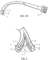
- the mounting unit 44 may extend to the distal end of the insertion tube 12 or may end proximal thereto (see Figures 1 B-D ).
- the mounting unit 44 extends proximally to a hub 45 through which other devices may be introduced through the endoscope.
- each of the outer rails 20 is formed longitudinally along the outer surface 14 of the insertion tube 12.
- each of the outer rails 20 extends distally on the outer surface 14 to the distal end 113 of the insertion tube 12.
- the outer rail 20 is formed with increased prominence distally along the outer surface, having an increased area or depth between each adjacent outer rail 20 at the distal end 113. This allows the mounting unit 44 (see Figure 1 D) to slidably cooperate with the outer surface 14 and attach the medical device 24 to the insertion tube 12.
- each of the outer rails 20 and mounting units 44 may take on any suitable shape. This is possible so long as each outer rail 20 and its corresponding mounting unit 44 are configured to complement each other such that when engaged with each other in a slidably cooperating relationship, the two units are slidably interlocked with each other. Furthermore, depending on the number of outer rails 20 formed on the insertion tube 12, the same number of medical devices 40 may be used with the insertion tube 12 during an endoscopic procedure.
- the insertion tube 12 comprises a proximal end 111 and a distal end 113.
- each outer rail 20 is formed on the insertion tube 12 from the proximal end 111 to the distal end 113 so that the medical device 24 may be slidably introduced at the proximal end 111 and advanced beyond the distal end 113.
- This may be accomplished by any suitable manner, e.g., by having a tapered formation of the first predetermined shape 22 near the proximal end of the insertion tube 12.
- the medical device may then be introduced and advanced at the tapered formation to slidably engage the insertion tube 12.
- a catheter may be advanced to a location beyond the distal end of the insertion tube 12 to a stricture within the anatomy otherwise unobtainable with the outer diameter size of a conventional endoscope.
- the outer rail formed on the insertion tube may simply be one outer rail or a plurality thereof.
- the insertion tube comprises one outer rail formed along the length of the insertion tube.
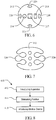
- the embodiment provided in Figure 6 includes four outer rails 220.
- the insertion tube 212 comprises four outer rails 220 having first predetermined shapes radially formed about the outer surface of the insertion tube.
- each of the outer rails 220 has a first predetermined shape that is the same as the others.
- the apparatus comprises an illumination channel 216 through which a fiberoptic cable is inserted for the transmission of light from a light source.
- the apparatus comprises a viewing channel 217 having a fiberoptic cable for viewing purposes and a third channel 218 for application of fluid or suction at the surgical site.
- a corresponding mounting unit having a second predetermined shape of a medical device may be used to slidably attach to the outer rail in the similar manner as described above.
- a series of accessory channels would be able to engage the outer rail. This would allow the user flexibility during the procedure because the channel could be interchanged or swapped as desired.
- the embodiment provided in Figure 7 includes two outer rails 320 formed on the insertion tube 312, each of which having a first predetermined shape that is the same as the other.
- a corresponding mounting unit has a second predetermined shape that may be used to slidably attach to the outer rail in the similar manner as described above.
- a series of accessory channels would be able to engage the outer rail. This would allow the user flexibility during the procedure because the channel could be interchanged or swapped as desired.
- the apparatus also includes inner channels similar to the inner channels mentioned above.
- Figure 8 illustrates a flow chart of one method 410 of using the endoscopic apparatus discussed above having an outer rail system for endoscopic treatment.
- the method comprises introducing the endoscopic apparatus in the gastrointestinal tract of a patient to an interventional location therein in box 412 and maintaining position of the apparatus at the interventional location in box 414.
- the method 410 further includes introducing a medical device through the proximal end of the insertion tube.
- the mounting unit is configured to slidably mate with the outer rail of the insertion tube for attaching a medical device thereto. In this example, this may be accomplished by having the outer rail formed on the outer surface at a proximal portion of the insertion tube.
- the outer rail may be formed to proximally taper or distally flare to receive the mounting unit which may be slidably attached therewith.
- the mounting unit may extend proximally from the insertion tube to a port through which a medical device may be disposed for introduction thereof into the patient.
- the method 410 further comprises advancing the medical device beyond the distal end of the insertion tube for enhanced endoscopic treatment that allows a clinician the ability to use various sizes of medical devices with one endoscope while maintaining longitudinal positioning within a patient's gastrointestinal anatomy in box 416.
- the medical device is preferably provided separately from the endoscopic apparatus with the outer rail(s) already formed along the outer surface of the insertion tube. At a desired time during the use of the flexible insertion tube, the medical device can be slidably engaged along the length of the outer surface of the insertion tube. The medical device may be introduced at the proximal end thereof and then may be slidably advanced beyond the distal end of the insertion tube to a desired location within the anatomy of a patient. Additionally, scope repairs would be reduced as the scope would not have to be sent out for repairs to the accessory channel.
Landscapes
- Health & Medical Sciences (AREA)
- Life Sciences & Earth Sciences (AREA)
- Surgery (AREA)
- Biomedical Technology (AREA)
- Medical Informatics (AREA)
- Optics & Photonics (AREA)
- Pathology (AREA)
- Radiology & Medical Imaging (AREA)
- Biophysics (AREA)
- Engineering & Computer Science (AREA)
- Physics & Mathematics (AREA)
- Heart & Thoracic Surgery (AREA)
- Nuclear Medicine, Radiotherapy & Molecular Imaging (AREA)
- Molecular Biology (AREA)
- Animal Behavior & Ethology (AREA)
- General Health & Medical Sciences (AREA)
- Public Health (AREA)
- Veterinary Medicine (AREA)
- Endoscopes (AREA)
- Surgical Instruments (AREA)
Description
- The present invention relates to endoscopic apparatus having outer rail guide systems.
- Endoscopic devices have been commonly used for various procedures, typically in the abdominal area. Endoscopy is the examination and inspection of the interior of body organs, joints or cavities through an endoscope. Endoscopy allows physicians to peer through the body's passageways. An endoscopic procedure may be used to diagnose various conditions by close examination of internal organ and body structures and may also guide therapy and repair, such as the removal of torn cartilage from the bearing surfaces of a joint. A biopsy, a procedure involving tissue sampling for pathologic testing, may also be performed under endoscopic guidance. For example, endoscopic procedures include the following known procedures: gastroscopy, sigmoidoscopy and colonoscopy, esophago gastro duodenoscopy (EGD), endoscopic retrograde cholangiopancreatography (ERCP), and bronchoscopy.
- An endoscope typically includes at least one separate port or working channel. Such port(s) may be used to introduce endoscopic instruments such as catheters, forceps, scissors, brushes, snares or baskets for tissue excision, sampling, or other diagnostic and therapeutic work. The inner diameter of such working channels or ports may vary based on the instruments used during an endoscopic procedure, affecting the overall outer diameter size of the insertion tube of the endoscope. The differences in diameter typically affect the resulting size of the outer diameter of the endoscope. Moreover, as clinicians may use a number of various sized medical devices during an endoscopic procedure, they face challenges in maintaining wire guide position in certain anatomy, e.g., within the biliary tree, while executing an endoscopic procedure.
- Thus, it is desirable to provide an improved endoscope apparatus that allows a clinician the ability to use various sizes of medical devices with one endoscope while maintaining longitudinal positioning within a patient's gastrointestinal anatomy.
- Reference is directed to
EP 1477105 which discloses a guide system for use with an endoscope, and a method of use. The guide system can include a track, in the form of a rail, and a mating member for engaging the rail. The guide system can also include an accessory, such as an accessory guide tube through which a medical instrument can be carried external of the endoscope. An end cap can be provided to support the track relative to the distal end of the endoscope. - The present invention generally provides an outer rail endoscopic apparatus including an outer rail guide system that allows a clinician the ability to use various sizes of medical devices with one endoscope while maintaining longitudinal positioning within a patient's gastrointestinal anatomy.
- In one embodiment, the present invention provides an endoscope apparatus for endoscopic treatment. The apparatus comprises an endoscopic insertion tube comprising an outer surface including an outer rail formed longitudinally thereon and extending along a portion of the insertion tube. The outer rail has a predetermined shape. The insertion tube comprises an inner channel formed therethrough. An endoscope apparatus for endoscopic treatment is disclosed. The apparatus comprises an endoscopic insertion tube without a working channel and an outer surface including at least one outer rail formed longitudinally thereon and extending along a portion of the insertion tube. The outer rail has a first predetermined shape. At least one medical device includes an outer wall having at least one mounting unit formed thereon along a portion of the length of the outer wall. The mounting unit has a second predetermined shape cooperable with the first predetermined shape. The second predetermined shape is formed to complement and slidably cooperate with the first predetermined shape of the outer rail for slidably attaching the medical device thereto.
- In another embodiment, the present invention provides an endoscopic apparatus having an outer rail system for endoscopic treatment. The apparatus comprises the endoscopic apparatus and at least one medical device including an outer wall having at least one mounting unit formed thereon along the length of the outer wall. The mounting unit is configured to slidably mate with the outer rail of the insertion tube for attaching the medical device thereto.
- In yet another example, the present invention provides a method of using an endoscopic apparatus having an outer rail system for endoscopic treatment. The method comprises introducing the endoscopic apparatus in the gastrointestinal tract of a patient to an interventional location therein. The method further comprises maintaining position of the apparatus at the interventional location and introducing the medical device through the proximal end of the insertion tube. The method further comprises advancing the medical device beyond the distal end of the insertion tube for enhanced endoscopic treatment.
- Further objects, features, and advantages of the present invention will become apparent from consideration of the following description and the appended claims when taken in connection with the accompanying drawings.
-
-
Figure 1A is an elevated view of an outer rail endoscopic apparatus in accordance with one embodiment of the present invention; -
Figure 1 B is a side view of the insertion tube of the apparatus ofFigure 1A ; -
Figure 1C is a partial view of the insertion tube of the endoscopic apparatus ofFigure 1A ; -
Figure 1D is a perspective view of a medical device that cooperates with the insertion tube of the endoscopic apparatus ofFigure 1A ; -
Figure 2 is a partial exploded view of the apparatus ofFigure 1A ; -
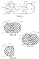
Figure 3A is an end view of the apparatus ofFigure 1A ; -
Figure 3B is a cross-sectional view of the apparatus of 1A taken alongline 3B-3B; -
Figure 3C is a cross-sectional view of the apparatus of 1A taken alongline 3C-3C; -
Figure 3D is a cross-sectional view of the apparatus of 1A taken alongline 3D-3D; -
Figure 4 is a partial view of the apparatus ofFigure 1A ; -
Figure 5 is an end view of the apparatus ofFigure 4 ; -
Figure 6 is an end view of the apparatus in accordance with another embodiment of the present invention; -
Figure 7 is an end view of an apparatus in accordance with yet another embodiment of the present invention; and -
Figure 8 is a flow chart of one method of using the endoscopic apparatus ofFigure 1 in accordance with one example of the present invention. - The present invention generally provides an outer rail endoscopic apparatus that allows a clinician the ability to use various sizes of medical devices with one endoscope while maintaining longitudinal positioning within a patient's gastrointestinal anatomy. This feature also allows for a smaller or relatively reduced diametric size of the insertion tube. The reduced diameter of the insertion tube allows the clinician to be able to more easily perform an endoscopic treatment within a patient's anatomy (e.g., within the biliary duct) that otherwise would not be possible or would be a relatively high risk procedure. Each of the embodiments of the present invention comprises an insertion tube having an outer surface with an outer rail. Each outer rail is configured to cooperate with a mounting unit formed on a medical device (e.g., a wire guide or catheter) to be used during the endoscopic treatment. The medical device is slidably attachable to the side of the insertion tube at its proximal end and is distally advanced beyond the distal end of the insertion tube. This aspect allows enhanced positioning and treatment in areas of the anatomy otherwise unobtainable. Additionally, scope repairs would be reduced as the scope would not have to be sent out for repairs to the accessory channel.
-
Figure 1A illustrates anendoscopic apparatus 10 having an outer rail system for enhanced endoscopic treatment in accordance with one embodiment of the present invention. As shown, theendoscopic apparatus 10 comprises aflexible insertion tube 12 and acontrol system 13 in communication with theinsertion tube 12. As shown inFigures 1A and1B , theflexible insertion tube 12 comprises anouter surface 14 including at least oneouter rail 20 formed thereon. Preferably, theouter rail 20 comprises a first predetermined portion or shape 22 (discussed in greater detail below) to accommodate a complementary shape for attaching amedical device 24 thereto. In this embodiment, theouter rail 20 is formed on theouter surface 14 along the length of theinsertion tube 12. - The
outer rail 20 is formed on theouter surface 14 of theinsertion tube 12 and replaces a conventional endoscopic working channel typically formed through theinsertion tube 12 of an endoscope, thereby defining a smaller or reduced diametric size of theinsertion tube 12. Theouter rail 20 is configured to allow amedical device 24, e.g., a wire guide, to be slidably interlocked therewith and advanced relative to theinsertion tube 12. The firstpredetermined shape 22 of theouter rail 20 may take on any suitable shape that allows a complementary or cooperating shape to be able to slide through and lock itself thereon. For example, as shown inFigures 2-5 , theouter rail 20 of theinsertion tube 12 is an interlocking rack that is configured to interlock with a complementing or cooperating shape formed along the length of amedical device 24, e.g., a wire guide or catheter. Themedical device 24 may be distally advanced beyond the distal end of theinsertion tube 12 to reach areas of an anatomy otherwise unobtainable by a conventional endoscope. - As mentioned above, the
outer rail 20 replaces a conventional endoscopic working channel typically formed through theinsertion tube 12. As shown, theinsertion tube 12 does not have a conventional endoscopic working channel. Rather, theinsertion tube 12 comprises at least one inner channel in which endoscopic components are disposed, defining a reduced outer diameter occupied by theinsertion tube 12. In this embodiment, the endoscopic components vary depending on the purpose of use for the endoscope. For example, theapparatus 10 includes any number of inner channels. In this embodiment, there are three inner channels shown inFigures 1A-5 . As shown, anillumination channel 32 is formed through theinsertion tube 12 through which a fiberoptic cable is inserted for the transmission of light from a light source. Moreover, aviewing channel 34 can also be provided with a fiberoptic cable for viewing purposes and afluid channel 36 can be provided for application of suction at the surgical site. In another example, the inner channel may be a fluid channel, a light channel, and a camera channel formed through the insertion tube to allow for fluid, light, and a camera, respectively therethrough. - The
endoscopic apparatus 10 shown inFigures 1A further comprises acontrol system 13 in mechanical and fluid communication with theinsertion tube 12. Thecontrol system 13 is configured to control at least one of the endoscopic components. It is to be understood that any other suitable endoscopicoperating control system 13 may be used with theinsertion tube 12 described above without falling beyond the scope of the present invention. In one embodiment, thecontrol system 13 includes anauxiliary port portion 123 having aproximal opening 124. Thefluid channel 36 extends into theauxiliary port 123 by way of afluid channel extension 119a. Each of the channels preferably opens at the distal orinsertion end 113 of theflexible section 12 of theendoscopic apparatus 10. - The
control system 13 of theendoscopic apparatus 10 shown inFigure 1A can be of many different types so long as it is in fluid and mechanical communication with the inner channels formed through theinsertion tube 12 of theendoscopic apparatus 10. While most of the working components of thesecontrol systems 13 are similar, each may have a different configuration without falling beyond the scope of the present invention. For example, the proximal opening and the auxiliary port may differ amongst each other. Each of these specifically identified control systems, and other commercially available endoscopes, utilize different sealing members (not shown) at the proximal opening of the auxiliary port. It is understood that the various aspects of the present invention accommodate the secure attachment to various configurations and dimensions of a variety of endoscopes. - As shown, the
endoscopic apparatus 10 further comprises at least onemedical device 24 having anouter wall 42 comprising at least one mountingunit 44 formed thereon along the length of theouter wall 42. In this embodiment, the mountingunit 44 is configured to slidably mate with theouter rail 20 of theinsertion tube 12 for slidably attaching themedical device 24 thereto. Preferably, the mountingunit 44 has a second predetermined portion orshape 46 cooperable with the firstpredetermined shape 22. The secondpredetermined shape 46 is formed to complement and slidably cooperate with the firstpredetermined shape 22 of theouter rail 20 for slidably attaching the medical device thereto. - In this example, this is accomplished by having the second
predetermined shape 46 take on a complementing shape relative to the firstpredetermined shape 22. As shown inFigures 2-5 , themedical device 24 slidably interlocks with theinsertion tube 12 due to the cooperating relationship between theouter rail 20 and the mountingunit 44. - In this example, the
outer rail 20 is configured to proximally taper or distally flare longitudinally along theouter surface 14 of theinsertion tube 12 to receive the mountingunit 44. As shown inFigures 1A ,2 , and3A-D , the mountingunit 44 is slidably received by theouter rail 20 at a proximal portion of theinsertion tube 12. The mountingunit 44 extends distally along theinsertion tube 12. Although not necessarily, the mountingunit 44 may extend to the distal end of theinsertion tube 12 or may end proximal thereto (seeFigures 1 B-D ). Moreover, in this embodiment, the mountingunit 44 extends proximally to ahub 45 through which other devices may be introduced through the endoscope. - As shown in
Figure 1C , in one example, each of theouter rails 20 is formed longitudinally along theouter surface 14 of theinsertion tube 12. Preferably, each of theouter rails 20 extends distally on theouter surface 14 to thedistal end 113 of theinsertion tube 12. In this embodiment, theouter rail 20 is formed with increased prominence distally along the outer surface, having an increased area or depth between each adjacentouter rail 20 at thedistal end 113. This allows the mounting unit 44 (seeFigure 1 D) to slidably cooperate with theouter surface 14 and attach themedical device 24 to theinsertion tube 12. - It is to be understood that each of the
outer rails 20 and mountingunits 44 may take on any suitable shape. This is possible so long as eachouter rail 20 and its corresponding mountingunit 44 are configured to complement each other such that when engaged with each other in a slidably cooperating relationship, the two units are slidably interlocked with each other. Furthermore, depending on the number ofouter rails 20 formed on theinsertion tube 12, the same number of medical devices 40 may be used with theinsertion tube 12 during an endoscopic procedure. - In this embodiment, the
insertion tube 12 comprises aproximal end 111 and adistal end 113. Preferably, eachouter rail 20 is formed on theinsertion tube 12 from theproximal end 111 to thedistal end 113 so that themedical device 24 may be slidably introduced at theproximal end 111 and advanced beyond thedistal end 113. This may be accomplished by any suitable manner, e.g., by having a tapered formation of the firstpredetermined shape 22 near the proximal end of theinsertion tube 12. The medical device may then be introduced and advanced at the tapered formation to slidably engage theinsertion tube 12. In use, e.g., a catheter, may be advanced to a location beyond the distal end of theinsertion tube 12 to a stricture within the anatomy otherwise unobtainable with the outer diameter size of a conventional endoscope. - It is to be noted that the outer rail formed on the insertion tube may simply be one outer rail or a plurality thereof. In the embodiment shown in
Figures 1 a-5 , the insertion tube comprises one outer rail formed along the length of the insertion tube. However, the embodiment provided inFigure 6 includes fourouter rails 220. As shown, theinsertion tube 212 comprises fourouter rails 220 having first predetermined shapes radially formed about the outer surface of the insertion tube. In this embodiment, each of theouter rails 220 has a first predetermined shape that is the same as the others. As shown, the apparatus comprises anillumination channel 216 through which a fiberoptic cable is inserted for the transmission of light from a light source. Moreover, the apparatus comprises aviewing channel 217 having a fiberoptic cable for viewing purposes and athird channel 218 for application of fluid or suction at the surgical site. A corresponding mounting unit having a second predetermined shape of a medical device (not shown) may be used to slidably attach to the outer rail in the similar manner as described above. Thus, a series of accessory channels would be able to engage the outer rail. This would allow the user flexibility during the procedure because the channel could be interchanged or swapped as desired. - The embodiment provided in
Figure 7 includes twoouter rails 320 formed on theinsertion tube 312, each of which having a first predetermined shape that is the same as the other. A corresponding mounting unit has a second predetermined shape that may be used to slidably attach to the outer rail in the similar manner as described above. Thus, a series of accessory channels would be able to engage the outer rail. This would allow the user flexibility during the procedure because the channel could be interchanged or swapped as desired. In this embodiment, the apparatus also includes inner channels similar to the inner channels mentioned above. -
Figure 8 illustrates a flow chart of onemethod 410 of using the endoscopic apparatus discussed above having an outer rail system for endoscopic treatment. As shown, the method comprises introducing the endoscopic apparatus in the gastrointestinal tract of a patient to an interventional location therein inbox 412 and maintaining position of the apparatus at the interventional location inbox 414. Themethod 410 further includes introducing a medical device through the proximal end of the insertion tube. The mounting unit is configured to slidably mate with the outer rail of the insertion tube for attaching a medical device thereto. In this example, this may be accomplished by having the outer rail formed on the outer surface at a proximal portion of the insertion tube. The outer rail may be formed to proximally taper or distally flare to receive the mounting unit which may be slidably attached therewith. The mounting unit may extend proximally from the insertion tube to a port through which a medical device may be disposed for introduction thereof into the patient. - The
method 410 further comprises advancing the medical device beyond the distal end of the insertion tube for enhanced endoscopic treatment that allows a clinician the ability to use various sizes of medical devices with one endoscope while maintaining longitudinal positioning within a patient's gastrointestinal anatomy inbox 416. - The medical device is preferably provided separately from the endoscopic apparatus with the outer rail(s) already formed along the outer surface of the insertion tube. At a desired time during the use of the flexible insertion tube, the medical device can be slidably engaged along the length of the outer surface of the insertion tube. The medical device may be introduced at the proximal end thereof and then may be slidably advanced beyond the distal end of the insertion tube to a desired location within the anatomy of a patient. Additionally, scope repairs would be reduced as the scope would not have to be sent out for repairs to the accessory channel.
- While the present invention has been described in terms of preferred embodiments, it will be understood, of course, that the invention is not limited thereto since modifications may be made to those skilled in the art, particularly in light of the foregoing teachings.
Claims (8)
- An endoscopic apparatus (10) having an outer rail system for endoscopic treatment, the apparatus comprising:an endoscopic insertion tube (12) comprising an outer surface (14) including at least one outer rail (20) formed longitudinally thereon and extending along a portion of the insertion tube, the outer rail having a predetermined shape, the insertion tube comprising an inner channel formed therethrough; andat least one medical device (24) including an outer wall (42) having at least one mounting unit (44) formed thereon along the length of the outer wall, the mounting unit being configured to slidably mate with the outer rail of the insertion tube for attaching the medical device thereto;characterized in that the outer rail (20) proximally tapers or distally flares longitudinally along the outer surface (14) of the insertion tube (12) to receive the mounting unit (44).
- The apparatus of claim 1 wherein the outer rail has a first predetermined shape and the mounting unit has a second predetermined shape cooperable with the first predetermined shape; the second predetermined shape formed to complement and slidably cooperate with the first predetermined shape of the outer rail.
- The apparatus of claim 2 wherein the at least one outer rail comprises first and second outer rails formed on the outer surface.
- The apparatus of claim 3 wherein the at least one medical device comprises first and second medical devices, each having mounting units formed thereon and configured to mate with one of the first and second outer rails.
- The apparatus of claim 2 wherein the insertion tube comprises a proximal end and a distal end, each outer rail being formed on the insertion tube from the proximal and distal ends so that the medical device may be slidably introduced at the proximal end and advanced beyond the distal end.
- The apparatus of claim 2 wherein the at least one outer rail comprises four outer rails formed on the outer surface of the insertion tube.
- The apparatus of claim 6 wherein the at least one inner channel comprises a fluid channel, a light channel, and a camera channel formed through the insertion tube for endoscopic treatment.
- The apparatus of claim 1, wherein the insertion tube has no working channel.
Applications Claiming Priority (2)
| Application Number | Priority Date | Filing Date | Title |
|---|---|---|---|
| US92138607P | 2007-04-02 | 2007-04-02 | |
| PCT/US2008/059114 WO2008122033A1 (en) | 2007-04-02 | 2008-04-02 | Endoscopic apparatus having an outer rail |
Publications (2)
| Publication Number | Publication Date |
|---|---|
| EP2136696A1 EP2136696A1 (en) | 2009-12-30 |
| EP2136696B1 true EP2136696B1 (en) | 2017-05-17 |
Family
ID=39712453
Family Applications (1)
| Application Number | Title | Priority Date | Filing Date |
|---|---|---|---|
| EP08744921.1A Active EP2136696B1 (en) | 2007-04-02 | 2008-04-02 | Endoscopic apparatus having an outer rail |
Country Status (6)
| Country | Link |
|---|---|
| US (1) | US9254077B2 (en) |
| EP (1) | EP2136696B1 (en) |
| JP (1) | JP5388371B2 (en) |
| AU (1) | AU2008232437B2 (en) |
| CA (1) | CA2682854A1 (en) |
| WO (1) | WO2008122033A1 (en) |
Families Citing this family (14)
| Publication number | Priority date | Publication date | Assignee | Title |
|---|---|---|---|---|
| US9962066B2 (en) * | 2005-12-30 | 2018-05-08 | Intuitive Surgical Operations, Inc. | Methods and apparatus to shape flexible entry guides for minimally invasive surgery |
| US20080065101A1 (en) | 2006-06-13 | 2008-03-13 | Intuitive Surgical, Inc. | Minimally invasive surgical apparatus with side exit instruments |
| DE102009060718A1 (en) * | 2009-12-29 | 2011-06-30 | Richard Wolf GmbH, 75438 | Endoscopic instrument |
| WO2014157477A1 (en) * | 2013-03-29 | 2014-10-02 | 富士フイルム株式会社 | Endoscopic surgery device |
| JP6623462B2 (en) * | 2015-03-12 | 2019-12-25 | 学校法人慶應義塾 | Treatment tool insertion aid |
| US11122964B2 (en) * | 2015-03-12 | 2021-09-21 | Keio University | Treatment-instrument insertion aid |
| US10299812B2 (en) * | 2015-06-05 | 2019-05-28 | Cook Medical Technologies Llc | Medical device snare |
| US11067002B2 (en) * | 2016-12-06 | 2021-07-20 | General Electric Company | Gas turbine engine maintenance tool |
| TWI648034B (en) * | 2017-10-19 | 2019-01-21 | 醫百科技股份有限公司 | Assistant clamper having lens |
| WO2019176131A1 (en) * | 2018-03-16 | 2019-09-19 | オリンパス株式会社 | Endoscope and endoscope system |
| US11986163B2 (en) * | 2018-12-28 | 2024-05-21 | Hoya Corporation | Endoscope and endoscope system controlled by pair of cable bundles |
| WO2020227253A1 (en) * | 2019-05-08 | 2020-11-12 | Boston Scientific Scimed, Inc. | Medical systems, devices, and related methods |
| US11974720B2 (en) | 2020-07-15 | 2024-05-07 | Boston Scientific Scimed, Inc. | Medical device accessory mounting system |
| CN113384229B (en) * | 2021-06-17 | 2023-10-27 | 湖南中聚内窥镜有限公司 | Electronic cystoscope |
Family Cites Families (12)
| Publication number | Priority date | Publication date | Assignee | Title |
|---|---|---|---|---|
| JPS568642Y2 (en) * | 1975-04-17 | 1981-02-25 | ||
| DE69321963T2 (en) * | 1992-09-01 | 1999-04-01 | Adair Edwin Lloyd | STERILIZABLE ENDOSCOPE WITH A DETACHABLE DISPOSABLE PIPE ARRANGEMENT |
| US5590660A (en) * | 1994-03-28 | 1997-01-07 | Xillix Technologies Corp. | Apparatus and method for imaging diseased tissue using integrated autofluorescence |
| US5944654A (en) * | 1996-11-14 | 1999-08-31 | Vista Medical Technologies, Inc. | Endoscope with replaceable irrigation tube |
| EP1109511B1 (en) * | 1998-08-31 | 2003-11-26 | Wilson-Cook Medical Inc. | Anti-reflux esophageal prosthesis |
| DE19906191A1 (en) * | 1999-02-15 | 2000-08-17 | Ingo F Herrmann | Mouldable endoscope for transmitting light and images with supplementary device has non-round cross section along longitudinal section for inserting in human or animal body opening |
| US6569085B2 (en) * | 2001-08-16 | 2003-05-27 | Syntheon, Llc | Methods and apparatus for delivering a medical instrument over an endoscope while the endoscope is in a body lumen |
| DE10139153A1 (en) * | 2001-08-09 | 2003-02-27 | Ingo F Herrmann | Disposable endoscope sheath |
| US7815565B2 (en) | 2003-05-16 | 2010-10-19 | Ethicon Endo-Surgery, Inc. | Endcap for use with an endoscope |
| US7431694B2 (en) * | 2003-05-16 | 2008-10-07 | Ethicon Endo-Surgery, Inc. | Method of guiding medical devices |
| US7029435B2 (en) * | 2003-10-16 | 2006-04-18 | Granit Medical Innovation, Llc | Endoscope having multiple working segments |
| US20070106113A1 (en) * | 2005-11-07 | 2007-05-10 | Biagio Ravo | Combination endoscopic operative delivery system |
-
2008
- 2008-04-02 CA CA002682854A patent/CA2682854A1/en not_active Abandoned
- 2008-04-02 WO PCT/US2008/059114 patent/WO2008122033A1/en active Application Filing
- 2008-04-02 JP JP2010502258A patent/JP5388371B2/en active Active
- 2008-04-02 EP EP08744921.1A patent/EP2136696B1/en active Active
- 2008-04-02 AU AU2008232437A patent/AU2008232437B2/en not_active Ceased
- 2008-04-02 US US12/061,229 patent/US9254077B2/en active Active
Non-Patent Citations (1)
| Title |
|---|
| None * |
Also Published As
| Publication number | Publication date |
|---|---|
| WO2008122033A1 (en) | 2008-10-09 |
| US20080249357A1 (en) | 2008-10-09 |
| EP2136696A1 (en) | 2009-12-30 |
| JP2010523219A (en) | 2010-07-15 |
| AU2008232437A1 (en) | 2008-10-09 |
| AU2008232437B2 (en) | 2013-10-03 |
| US9254077B2 (en) | 2016-02-09 |
| JP5388371B2 (en) | 2014-01-15 |
| CA2682854A1 (en) | 2008-10-09 |
Similar Documents
| Publication | Publication Date | Title |
|---|---|---|
| EP2136696B1 (en) | Endoscopic apparatus having an outer rail | |
| US20200178767A1 (en) | Endoscope accessory and medical device kit | |
| US10869658B2 (en) | Devices for introducing multiple instruments and methods of use | |
| AU2003266436B2 (en) | Locally-propelled, intraluminal device with cable loop track and method of use | |
| US8579802B2 (en) | Flexible endoscope with modifiable stiffness | |
| US20070287885A1 (en) | Endoscopic apparatus having an expandable balloon delivery system | |
| JP2007532240A (en) | Method and apparatus for obtaining intraluminal access | |
| US20070208220A1 (en) | Endoscopic delivery apparatus having a catheter with radial grooves | |
| AU2007257793A1 (en) | Endoscopic apparatus having an expandable balloon delivery system | |
| JP4601943B2 (en) | Endoscope | |
| US9844649B2 (en) | Telescopic wire guide | |
| US7993287B2 (en) | Endoscopic wire guide | |
| US20230172435A1 (en) | Endoscope companion devices with locking elements | |
| JP5557237B2 (en) | Small diameter endoscope and small diameter endoscope set | |
| JP5414727B2 (en) | Drainage tube insertion tool |
Legal Events
| Date | Code | Title | Description |
|---|---|---|---|
| PUAI | Public reference made under article 153(3) epc to a published international application that has entered the european phase |
Free format text: ORIGINAL CODE: 0009012 |
|
| 17P | Request for examination filed |
Effective date: 20090930 |
|
| AK | Designated contracting states |
Kind code of ref document: A1 Designated state(s): AT BE BG CH CY CZ DE DK EE ES FI FR GB GR HR HU IE IS IT LI LT LU LV MC MT NL NO PL PT RO SE SI SK TR |
|
| DAX | Request for extension of the european patent (deleted) | ||
| RAP1 | Party data changed (applicant data changed or rights of an application transferred) |
Owner name: COOK MEDICAL TECHNOLOGIES LLC |
|
| RAP1 | Party data changed (applicant data changed or rights of an application transferred) |
Owner name: COOK MEDICAL TECHNOLOGIES LLC |
|
| 17Q | First examination report despatched |
Effective date: 20151023 |
|
| GRAP | Despatch of communication of intention to grant a patent |
Free format text: ORIGINAL CODE: EPIDOSNIGR1 |
|
| INTG | Intention to grant announced |
Effective date: 20161020 |
|
| GRAJ | Information related to disapproval of communication of intention to grant by the applicant or resumption of examination proceedings by the epo deleted |
Free format text: ORIGINAL CODE: EPIDOSDIGR1 |
|
| GRAR | Information related to intention to grant a patent recorded |
Free format text: ORIGINAL CODE: EPIDOSNIGR71 |
|
| GRAS | Grant fee paid |
Free format text: ORIGINAL CODE: EPIDOSNIGR3 |
|
| INTC | Intention to grant announced (deleted) | ||
| GRAA | (expected) grant |
Free format text: ORIGINAL CODE: 0009210 |
|
| INTG | Intention to grant announced |
Effective date: 20170329 |
|
| AK | Designated contracting states |
Kind code of ref document: B1 Designated state(s): AT BE BG CH CY CZ DE DK EE ES FI FR GB GR HR HU IE IS IT LI LT LU LV MC MT NL NO PL PT RO SE SI SK TR |
|
| REG | Reference to a national code |
Ref country code: GB Ref legal event code: FG4D |
|
| REG | Reference to a national code |
Ref country code: CH Ref legal event code: EP |
|
| REG | Reference to a national code |
Ref country code: IE Ref legal event code: FG4D |
|
| REG | Reference to a national code |
Ref country code: AT Ref legal event code: REF Ref document number: 893685 Country of ref document: AT Kind code of ref document: T Effective date: 20170615 |
|
| REG | Reference to a national code |
Ref country code: DE Ref legal event code: R096 Ref document number: 602008050324 Country of ref document: DE |
|
| REG | Reference to a national code |
Ref country code: NL Ref legal event code: MP Effective date: 20170517 |
|
| REG | Reference to a national code |
Ref country code: LT Ref legal event code: MG4D |
|
| REG | Reference to a national code |
Ref country code: AT Ref legal event code: MK05 Ref document number: 893685 Country of ref document: AT Kind code of ref document: T Effective date: 20170517 |
|
| PG25 | Lapsed in a contracting state [announced via postgrant information from national office to epo] |
Ref country code: NO Free format text: LAPSE BECAUSE OF FAILURE TO SUBMIT A TRANSLATION OF THE DESCRIPTION OR TO PAY THE FEE WITHIN THE PRESCRIBED TIME-LIMIT Effective date: 20170817 Ref country code: LT Free format text: LAPSE BECAUSE OF FAILURE TO SUBMIT A TRANSLATION OF THE DESCRIPTION OR TO PAY THE FEE WITHIN THE PRESCRIBED TIME-LIMIT Effective date: 20170517 Ref country code: AT Free format text: LAPSE BECAUSE OF FAILURE TO SUBMIT A TRANSLATION OF THE DESCRIPTION OR TO PAY THE FEE WITHIN THE PRESCRIBED TIME-LIMIT Effective date: 20170517 Ref country code: HR Free format text: LAPSE BECAUSE OF FAILURE TO SUBMIT A TRANSLATION OF THE DESCRIPTION OR TO PAY THE FEE WITHIN THE PRESCRIBED TIME-LIMIT Effective date: 20170517 Ref country code: ES Free format text: LAPSE BECAUSE OF FAILURE TO SUBMIT A TRANSLATION OF THE DESCRIPTION OR TO PAY THE FEE WITHIN THE PRESCRIBED TIME-LIMIT Effective date: 20170517 Ref country code: FI Free format text: LAPSE BECAUSE OF FAILURE TO SUBMIT A TRANSLATION OF THE DESCRIPTION OR TO PAY THE FEE WITHIN THE PRESCRIBED TIME-LIMIT Effective date: 20170517 Ref country code: GR Free format text: LAPSE BECAUSE OF FAILURE TO SUBMIT A TRANSLATION OF THE DESCRIPTION OR TO PAY THE FEE WITHIN THE PRESCRIBED TIME-LIMIT Effective date: 20170818 |
|
| PG25 | Lapsed in a contracting state [announced via postgrant information from national office to epo] |
Ref country code: BG Free format text: LAPSE BECAUSE OF FAILURE TO SUBMIT A TRANSLATION OF THE DESCRIPTION OR TO PAY THE FEE WITHIN THE PRESCRIBED TIME-LIMIT Effective date: 20170817 Ref country code: LV Free format text: LAPSE BECAUSE OF FAILURE TO SUBMIT A TRANSLATION OF THE DESCRIPTION OR TO PAY THE FEE WITHIN THE PRESCRIBED TIME-LIMIT Effective date: 20170517 Ref country code: NL Free format text: LAPSE BECAUSE OF FAILURE TO SUBMIT A TRANSLATION OF THE DESCRIPTION OR TO PAY THE FEE WITHIN THE PRESCRIBED TIME-LIMIT Effective date: 20170517 Ref country code: IS Free format text: LAPSE BECAUSE OF FAILURE TO SUBMIT A TRANSLATION OF THE DESCRIPTION OR TO PAY THE FEE WITHIN THE PRESCRIBED TIME-LIMIT Effective date: 20170917 Ref country code: SE Free format text: LAPSE BECAUSE OF FAILURE TO SUBMIT A TRANSLATION OF THE DESCRIPTION OR TO PAY THE FEE WITHIN THE PRESCRIBED TIME-LIMIT Effective date: 20170517 Ref country code: PL Free format text: LAPSE BECAUSE OF FAILURE TO SUBMIT A TRANSLATION OF THE DESCRIPTION OR TO PAY THE FEE WITHIN THE PRESCRIBED TIME-LIMIT Effective date: 20170517 |
|
| PG25 | Lapsed in a contracting state [announced via postgrant information from national office to epo] |
Ref country code: EE Free format text: LAPSE BECAUSE OF FAILURE TO SUBMIT A TRANSLATION OF THE DESCRIPTION OR TO PAY THE FEE WITHIN THE PRESCRIBED TIME-LIMIT Effective date: 20170517 Ref country code: CZ Free format text: LAPSE BECAUSE OF FAILURE TO SUBMIT A TRANSLATION OF THE DESCRIPTION OR TO PAY THE FEE WITHIN THE PRESCRIBED TIME-LIMIT Effective date: 20170517 Ref country code: DK Free format text: LAPSE BECAUSE OF FAILURE TO SUBMIT A TRANSLATION OF THE DESCRIPTION OR TO PAY THE FEE WITHIN THE PRESCRIBED TIME-LIMIT Effective date: 20170517 Ref country code: SK Free format text: LAPSE BECAUSE OF FAILURE TO SUBMIT A TRANSLATION OF THE DESCRIPTION OR TO PAY THE FEE WITHIN THE PRESCRIBED TIME-LIMIT Effective date: 20170517 Ref country code: RO Free format text: LAPSE BECAUSE OF FAILURE TO SUBMIT A TRANSLATION OF THE DESCRIPTION OR TO PAY THE FEE WITHIN THE PRESCRIBED TIME-LIMIT Effective date: 20170517 |
|
| REG | Reference to a national code |
Ref country code: DE Ref legal event code: R097 Ref document number: 602008050324 Country of ref document: DE |
|
| PG25 | Lapsed in a contracting state [announced via postgrant information from national office to epo] |
Ref country code: IT Free format text: LAPSE BECAUSE OF FAILURE TO SUBMIT A TRANSLATION OF THE DESCRIPTION OR TO PAY THE FEE WITHIN THE PRESCRIBED TIME-LIMIT Effective date: 20170517 |
|
| PLBE | No opposition filed within time limit |
Free format text: ORIGINAL CODE: 0009261 |
|
| STAA | Information on the status of an ep patent application or granted ep patent |
Free format text: STATUS: NO OPPOSITION FILED WITHIN TIME LIMIT |
|
| 26N | No opposition filed |
Effective date: 20180220 |
|
| PG25 | Lapsed in a contracting state [announced via postgrant information from national office to epo] |
Ref country code: SI Free format text: LAPSE BECAUSE OF FAILURE TO SUBMIT A TRANSLATION OF THE DESCRIPTION OR TO PAY THE FEE WITHIN THE PRESCRIBED TIME-LIMIT Effective date: 20170517 |
|
| PG25 | Lapsed in a contracting state [announced via postgrant information from national office to epo] |
Ref country code: MC Free format text: LAPSE BECAUSE OF FAILURE TO SUBMIT A TRANSLATION OF THE DESCRIPTION OR TO PAY THE FEE WITHIN THE PRESCRIBED TIME-LIMIT Effective date: 20170517 |
|
| REG | Reference to a national code |
Ref country code: CH Ref legal event code: PL |
|
| REG | Reference to a national code |
Ref country code: BE Ref legal event code: MM Effective date: 20180430 |
|
| PG25 | Lapsed in a contracting state [announced via postgrant information from national office to epo] |
Ref country code: LU Free format text: LAPSE BECAUSE OF NON-PAYMENT OF DUE FEES Effective date: 20180402 |
|
| PG25 | Lapsed in a contracting state [announced via postgrant information from national office to epo] |
Ref country code: LI Free format text: LAPSE BECAUSE OF NON-PAYMENT OF DUE FEES Effective date: 20180430 Ref country code: CH Free format text: LAPSE BECAUSE OF NON-PAYMENT OF DUE FEES Effective date: 20180430 Ref country code: BE Free format text: LAPSE BECAUSE OF NON-PAYMENT OF DUE FEES Effective date: 20180430 |
|
| PG25 | Lapsed in a contracting state [announced via postgrant information from national office to epo] |
Ref country code: FR Free format text: LAPSE BECAUSE OF NON-PAYMENT OF DUE FEES Effective date: 20180430 |
|
| PG25 | Lapsed in a contracting state [announced via postgrant information from national office to epo] |
Ref country code: MT Free format text: LAPSE BECAUSE OF NON-PAYMENT OF DUE FEES Effective date: 20180402 |
|
| PG25 | Lapsed in a contracting state [announced via postgrant information from national office to epo] |
Ref country code: TR Free format text: LAPSE BECAUSE OF FAILURE TO SUBMIT A TRANSLATION OF THE DESCRIPTION OR TO PAY THE FEE WITHIN THE PRESCRIBED TIME-LIMIT Effective date: 20170517 |
|
| PG25 | Lapsed in a contracting state [announced via postgrant information from national office to epo] |
Ref country code: HU Free format text: LAPSE BECAUSE OF FAILURE TO SUBMIT A TRANSLATION OF THE DESCRIPTION OR TO PAY THE FEE WITHIN THE PRESCRIBED TIME-LIMIT; INVALID AB INITIO Effective date: 20080402 Ref country code: PT Free format text: LAPSE BECAUSE OF FAILURE TO SUBMIT A TRANSLATION OF THE DESCRIPTION OR TO PAY THE FEE WITHIN THE PRESCRIBED TIME-LIMIT Effective date: 20170517 |
|
| PG25 | Lapsed in a contracting state [announced via postgrant information from national office to epo] |
Ref country code: CY Free format text: LAPSE BECAUSE OF FAILURE TO SUBMIT A TRANSLATION OF THE DESCRIPTION OR TO PAY THE FEE WITHIN THE PRESCRIBED TIME-LIMIT Effective date: 20170517 |
|
| P01 | Opt-out of the competence of the unified patent court (upc) registered |
Effective date: 20230602 |
|
| PGFP | Annual fee paid to national office [announced via postgrant information from national office to epo] |
Ref country code: DE Payment date: 20230320 Year of fee payment: 16 |
|
| PGFP | Annual fee paid to national office [announced via postgrant information from national office to epo] |
Ref country code: IE Payment date: 20240326 Year of fee payment: 17 |
|
| PGFP | Annual fee paid to national office [announced via postgrant information from national office to epo] |
Ref country code: GB Payment date: 20240314 Year of fee payment: 17 |