EP2136102A1 - Vibration control equipment - Google Patents
Vibration control equipment Download PDFInfo
- Publication number
- EP2136102A1 EP2136102A1 EP08739234A EP08739234A EP2136102A1 EP 2136102 A1 EP2136102 A1 EP 2136102A1 EP 08739234 A EP08739234 A EP 08739234A EP 08739234 A EP08739234 A EP 08739234A EP 2136102 A1 EP2136102 A1 EP 2136102A1
- Authority
- EP
- European Patent Office
- Prior art keywords
- pair
- control equipment
- outer tube
- damping
- vibration control
- Prior art date
- Legal status (The legal status is an assumption and is not a legal conclusion. Google has not performed a legal analysis and makes no representation as to the accuracy of the status listed.)
- Granted
Links
Images


Classifications
-
- F—MECHANICAL ENGINEERING; LIGHTING; HEATING; WEAPONS; BLASTING
- F16—ENGINEERING ELEMENTS AND UNITS; GENERAL MEASURES FOR PRODUCING AND MAINTAINING EFFECTIVE FUNCTIONING OF MACHINES OR INSTALLATIONS; THERMAL INSULATION IN GENERAL
- F16F—SPRINGS; SHOCK-ABSORBERS; MEANS FOR DAMPING VIBRATION
- F16F1/00—Springs
- F16F1/36—Springs made of rubber or other material having high internal friction, e.g. thermoplastic elastomers
- F16F1/373—Springs made of rubber or other material having high internal friction, e.g. thermoplastic elastomers characterised by having a particular shape
- F16F1/3732—Springs made of rubber or other material having high internal friction, e.g. thermoplastic elastomers characterised by having a particular shape having an annular or the like shape, e.g. grommet-type resilient mountings
- F16F1/3735—Multi-part grommet-type resilient mountings
-
- F—MECHANICAL ENGINEERING; LIGHTING; HEATING; WEAPONS; BLASTING
- F16—ENGINEERING ELEMENTS AND UNITS; GENERAL MEASURES FOR PRODUCING AND MAINTAINING EFFECTIVE FUNCTIONING OF MACHINES OR INSTALLATIONS; THERMAL INSULATION IN GENERAL
- F16F—SPRINGS; SHOCK-ABSORBERS; MEANS FOR DAMPING VIBRATION
- F16F3/00—Spring units consisting of several springs, e.g. for obtaining a desired spring characteristic
- F16F3/08—Spring units consisting of several springs, e.g. for obtaining a desired spring characteristic with springs made of a material having high internal friction, e.g. rubber
- F16F3/087—Units comprising several springs made of plastics or the like material
- F16F3/0873—Units comprising several springs made of plastics or the like material of the same material or the material not being specified
Definitions
- the present invention relates to a vibration control equipment for use in a cabin mount or engine mount of machines for agriculture or construction.
- the present application claims priority from Japanese Patent Application No. 2007-095292, filed on March 30, 2007 , the content of which is hereby incorporated by reference into this application.
- a vibration control equipment is interposed between the vibration generating body and the vibration receiving body so as to prevent or suppress vibration from being transmitted from the vibration generating body to the vibration receiving body.
- a vibration control equipment there is a sandwich-type vibration control equipment including a pair of damping rubbers and plate members placed on both sides of the damping rubbers.
- Each of the damping rubbers is composed of an outer tube formed substantially in the shape of a cylinder and has a flange portion formed at an axial outer end portion, an inner tube substantially in the shape of a cylinder disposed in the inside of the outer tube, and a rubber elastic body interposed between the outer tube and the inner tube.
- the pair of damping rubbers is connected to each other by abutting the axial inner ends thereof, so that the damping rubbers are axially clamped at the outside thereof by means of the pair of plate members.
- the pair of plate members is connected to each other by means of fastening members, such as bolts, penetrating through the inside of the pair of inner tubes (e.g., see Patent Document 1).
- the vibration transmitted from the engine to the vibration control equipment causes rolling vibration to be generated around a driving shaft of the engine.
- the mold cavity portions are disposed in a planar rolling direction, that is, a right and left direction (a horizontal direction perpendicular to an engine shaft), so that the damping rubbers are positioned in a circumferential direction.
- the circumferential direction of the damping rubbers is fixed by pressing the damping rubbers into holes of substantially cylindrical shape formed in the bracket member when assembling, with the circumferential direction of the damping rubbers being fixed. For this reason, there is a problem that the assembling work is complicated. Also, there is another problem that the production cost is increased since the press fitting process requires jigs for the press fitting.
- an object of the present invention is to provide a vibration control equipment which can dispose a mold cavity portion in line with a vibrating direction and can be easily assembled to reduce the production cost.
- the vibration control equipment including a pair of damping rubbers each having an outer tube, an axial outer end of the outer tube being provided with a flange portion extending outwardly in a radial direction, an inner tube disposed in the outer tube, and a rubber elastic body for connecting the outer tube and the inner tube, the damping rubbers being symmetrically disposed in a vertical direction; a pair of plate members, with the pair of damping rubbers being interposed between the pair of plate members; a bracket member interposed between the upper and lower flange portions of the pair of damping rubbers, and provided with a fixing hole, through which each outer tube of the pair of damping rubbers is inserted from an upper portion and a lower portion; and a fastening member that connects the pair of plate members.
- the bracket member is fixed to any one of a vibration generating body and a vibration receiving body, at least one of the pair of plate members is fixed to the other of the vibration generating body and the vibration receiving body, and the rubber elastic bodies are axially compressed through the pair of plate members by firmly fastening the fastening member.
- the outer tube has an outer diameter smaller than an inner diameter of the fixing hole; the rubber elastic bodies are compressively deformed by firmly fastening the fastening member, so that the flange portion comes into close contact with the bracket member to clamp the bracket member by the upper and lower flange portions; at least any one of the pair of rubber elastic bodies is provided with a mold cavity portion; and at least one of the pair of outer tubes is provided with a positioning portion for determining circumferential positions of the pair of damping rubbers with respect to the bracket member.
- the pair of damping rubbers are disposed on and under the bracket member, and the outer tube of one damping rubber is inserted into the fixing hole of the bracket member from the upper side of the bracket member.
- the outer tube of the other damping rubbers is inserted into the fixing hole of the bracket member from the lower side of the bracket member.
- the outer tubes have an outer diameter smaller than the inner diameter of the fixing hole, and a clearance is formed between the outer circumferential surface of the outer tube and the inner circumferential surface of the fixing hole. That is, the outer tubes are inserted into the fixing holes in a non-pressing state.
- each circumferential position of the damping rubbers is determined with respect to the bracket member by the positioning portion.
- the plate members are disposed on and under the pair of damping rubbers, and the upper and lower plate members are connected to each other by means of the fastening member penetrating the inside of the inner tube.
- the fastening member is fastened, the pair of damping rubbers is vertically pressed by the pair of plate members. Therefore, the axial inner ends of the pair of opposite inner tubes come into contact with each other.
- the rubber elastic body is axially compressed, and then is elastically deformed in such a way that it is radially expanded to the outside. Therefore, the flange portions of the outer tubes connected to the rubber elastic body come into close contact with the bracket member, and the bracket member is clamped between the upper and lower flange portions, so that the pair of the damping rubbers is fixed to the bracket member.
- the bracket member may be provided with an engaging portion which is engaged with the positioning portion.
- the positioning portion may be provided on the flange portion.
- the bracket member is provided with the engaging portion
- the engaging portion is provided on the upper surface or lower surface of the bracket member opposite to the flange portion of the outer tube, so that it is possible to easily manufacture the bracket member as compared with the case where the engaging portion is formed on the inner circumferential surface of the fixing hole.
- the pair of the outer tubes may be provided with the positioning portion.
- the circumferential position of one damping rubber and the circumferential position of the other damping rubber are respectively determined by the positioning portion, so that the mold cavity portion provided on one damping rubber and the mold cavity portion provided on the other damping rubber are respectively disposed in line with the vibrating direction of the vibration generating body.
- a damping rubber positioning portion may be provided between the pair of damping rubbers to determine the relative circumferential position between the pair of damping rubbers.
- the relative circumferential position between one damping rubber and the other damping rubber is determined by the damping rubber positioning portion, and there is no position difference between the pair of damping rubbers. Therefore, if the circumferential position of one damping rubber is determined with respect to the bracket member, the circumferential position of the other damping rubber is determined with respect to the bracket.
- the positioning portion is provided on the outer tube of one damping rubber and the positioning portion is not provided on the outer tube of the other damping rubber, if there is the damping rubber positioning portion, the circumferential position of the other damping rubber is determined with respect to the bracket member, so that it is possible to dispose the mold cavity portion provided on the other damping rubber in line with the vibrating direction.
- one of the pair of damping rubbers having the mold cavity portion may include an outer tube side segment body, in which an outer circumferential portion of the rubber elastic body is attached to the outer tube, and an inner tube side segment body, in which an inner circumferential portion of the rubber elastic body is attached to the inner tube to form the mold cavity portion.
- a segment body positioning portion may be provided between the segment bodies to determine the relative circumferential position between the segment bodies.
- the relative circumferential position between the pair of segment bodies is determined by the segment body positioning portion, and there is no position difference between the segment bodies. Therefore, if the circumferential position of the outer tube side segment body is determined by the positioning portion provided on the outer tube, the position of the other segment body assembled to the outer tube side segment body is determined, and the mold cavity portion provided on the inner tube side segment body is disposed in line with the vibrating direction.
- the mold cavity portion may be axially penetrated.
- the mold cavity portion may be a non-penetrating hole extending axially.
- the outer tubes of the damping rubbers are inserted into the fixing holes of the bracket member in the non-pressing state, and in order to dispose the position of the mold cavity portion in line with the vibrating direction of the vibration generating body, the circumferential position of the damping rubbers is determined with respect to the bracket member by the positioning portion. Therefore, it is possible to improve the vibration-resistance properties of the damping rubbers, while ensuring the support rigidity of the damping rubbers. Also, it is possible to easily assemble the vibration control equipment, and thus lower the production cost.
- a vibration control equipment 1 according to the first embodiment will now be described with reference to FIGs. 1 to 3 .
- the direction (horizontal direction) denoted by the symbol X shown in the figure is referred to as the front and rear direction
- the direction (the vertical direction) denoted by the symbol Y shown in the figure is referred to as the left and right direction
- the direction (the vertical direction) denoted by the symbol Z shown in the figure is referred to as the upward and downward direction.
- an opposite surface side (a lower side in (b) of FIG 2 ) facing the other damping rubber 2B (2A) is referred to as an axial inner side
- a side (an upper side in (b) of FIG 2 ) opposite to the surface is referred to as an axial outer side.
- the vibration control equipment 1 is applied as, for example, an engine mount for damping and absorbing vibration input from an engine (a vibration generating body), which is not shown, mounted on, for example, a construction machine, to suppress the vibration from being transmitted to a vehicle body (a vibration receiving body), which is not shown.
- the vibration of the engine is rolling vibration caused by a rotation around a driving shaft thereof, and the vibration control equipment damps and absorbs the rolling vibration.
- the driving shaft of the engine which is not shown is extended in the front and rear direction, but the vibrating direction of the engine is the left and right direction in planar view.
- the vibration control equipment 1 includes the pair of damping rubbers 2A and 2B, a bracket member 3, a pair of plate members 4A and 4B, and a fastening member 5.
- the damping rubber 2A (2B) includes an outer tube 20 of substantially cylindrical shape, an inner tube 21 of substantially cylindrical shape which has a diameter smaller than that of the outer tube 20, is disposed in the outer tube 20, and is spaced apart from the outer tube, and a rubber elastic body 22 interposed between the outer tube 20 and the inner tube 21.
- the outer tube 20 is provided at the axial outer end portion thereof with a flange portion 23 straightly protruding to the outside in a radial direction.
- the flange portion 23 is extended along the entire circumference of the outer tube 20.
- the flange portion 23 is provided with a positioning portion 24 for determining circumferential positions of the damping rubbers 2A and 2B with respect to the bracket member 3 so that mold cavity portions 26A and 26B described below are disposed in line with the vibrating direction of the engine which is not shown.
- the positioning portion 24 is a pin-shaped convex portion protruding toward an inner surface 23a of the axial inner side of the flange portion 23, and is engaged with an engaging portion 31 described below.
- the positioning portion 24 is provided on each pair of upper and lower outer tubes 20 and 20.
- the inner tube 21 is concentrically disposed in the outer tube 20, and has a whole length longer than that of the outer tube 20 so that the inner tube 21 protrudes from the outer tube 20 to the outside in the axial direction. Also, in the case where an external force is not applied, the end surface of the axial inner side of the inner tube 21 is placed at the axial outer side rather than the end surface of the axial inner side of the outer tube 20.
- the rubber elastic body 22 is adapted to resiliently connect the outer tube 20 with the inner tube 21, and is cure-adhered to the inner circumferential surface 20a of the outer tube 20 and the axial outer surface 23b of the flange portion 23 and also cure-adhered to the outer circumferential surface 21a of the inner tube 21.
- the rubber elastic body 22 is formed in the shape of taper, of which the diameter is gradually decreased towards the axial outer side, and the end surface 22a of the axial inner side of the rubber elastic body 22 is formed in a concave shape as a curved portion.
- the rubber elastic body 22 is provided in the end surface 22b of the axial outer side with a groove 25 extending in a circumferential direction along the entire circumference, the groove being formed in a U shape of a cross section.
- the rubber elastic body 22 is provided with the mold cavity portions 26A and 26B for lowering the rigidity in one direction to allow the damping rubbers 2A and 2B to have an anisotropic aspect.
- the mold cavity portions 26A and 26B are thinned-down portions formed by removing a portion of the rubber elastic body 22, and are through-holes extending in the axial direction.
- the mold cavity portions 26A and 26B are disposed at opposite positions, with the inner tube 21 being interposed therebetween in the radial direction.
- the mold cavity portions 26A and 26B are each formed in both directions, each deviated from the positioning portion 24 around the central axis O by 90° in a plan view of the damping rubbers 2A and 2B.
- the damping rubbers 2A and 2B constructed as described above are paired, as shown in FIG. 1 , in such a way that one damping rubber 2A is disposed vertically symmetrically with the other damping rubber 2B.
- the pair of damping rubbers 2A and 2B is disposed on the same axis in such a way that the end surfaces of the axial inner sides are layered on each other.
- the bracket member 3 is a thick plate member, and is fixed and substantially horizontally installed to any one of the engine and the vehicle body (not shown).
- the bracket member 3 is provided with a substantially circular fixing hole 30.
- each of the outer tubes 20 and 20 of the pair of damping rubbers 2A and 2B is disposed in the fixing hole 30.
- Upper and lower corners 30b and 30c of the fixing hole 30 are each chamfered over the entire circumference thereof.
- the peripheral portion of the fixing hole 30 formed in the bracket member 3 is disposed between the upper and lower flange portions 23 and 23 of the pair of damping rubbers 2A and 2B, and is clamped by the upper and lower flange portions 23 and 23.
- An engaging portion 31 which is engaged with the positioning portion 24 is formed at the peripheral portion of the fixing hole 30 formed in the bracket member 3.
- the engaging portion 31 has a through-hole 32 vertically penetrating the bracket member 3, and is formed in both the upper and lower surfaces 3a and 3b of the bracket member 3.
- a planar position of the engaging portion 31 is set so that the mold cavity portions 26A and 26B are disposed in line with the vibrating direction when the positioning portion 24 is engaged with the engaging portion 31. More specifically, the engaging portion 31 is formed at the position of the front and rear sides with respect to the central axis O.
- the pair of plate members 4A and 4B are plates pinching the pair of damping rubbers 2A and 2B vertically, and are attached to the axial outer ends of the pair of damping rubbers 2A and 2B. At least one of the pair of plate members 4A and 4B is fixed to either the engine or the vehicle body which is not shown. In other words, in the case where the bracket member 3 is fixed to the engine, the plate members 4A and 4B are fixed to the vehicle body, while in the case where the bracket member 3 is fixed to the vehicle body, the plate members 4A and 4B are fixed to the engine. Also, the pair of plate members 4A and 4B is provided with a bolt hole 40 through which a bolt 50 described below passes. The bolt hole 40 communicates with the inner tube 21.
- the fastening member 5 is adapted to connect the pair of plate members 4A and 4B, and has a bolt 50 and a nut 51.
- the bolt 50 is inserted into the bolt hole 40 of one plate member 4A from the axial outer side (the upper side in FIG 1 ) of the plate member 4A, and passes the pair of upper and lower inner tubes 21 and 21 and the bolt hole 40 of the other plate member 4B to protrude from the axial outer side (the lower side in FIG. 1 ) of the plate member 4B.
- a tip of the bolt 50 protruding from the bolt hole 40 of the other plate member 4B is threadably engaged with the nut 51.
- the above-mentioned vibration control equipment 1 is assembled as mentioned below.
- the pair of damping rubbers 2A and 2B are disposed on and under the bracket member 3, and the outer tube 20 of one damping rubber 2A is inserted into the fixing hole 30 of the bracket member 3 from the upper side of the bracket member 3.
- the outer tube 20 of the other damping rubbers 2B is inserted into the fixing hole 30 of the bracket member 3 from the lower side of the bracket member 3.
- the outer tubes 20 and 20 have an outer diameter smaller than the inner diameter of the fixing hole 30, and a clearance (approximately 0.2 to 1.3 mm) is formed to some extent between an outer circumferential surfaces 20b of the outer tubes 20 and 20 and an inner circumferential surface 30a of the fixing hole 30. That is, the outer tubes 20 and 20 are inserted into the fixing holes 30 in a non-pressing state.
- each circumferential position of the damping rubbers 2A and 2B is determined with respect to the bracket member 3 by the positioning portion 24. More specifically, the positioning portion 24 is inserted into the engaging portion 31 formed in the bracket member 3. Since the engaging portion 31 is formed at the front and rear sides with respect to the central axis O, the positioning portion 24 is positioned at the front and rear sides with respect to the central axis O.
- mold cavity portions 26A and 26B are respectively formed in both directions, each deviated from the positioning portion 24 around the central axis O by 90° in a plan view of the damping rubbers 2A and 2B, the mold cavity portions 26A and 26B are disposed in a direction perpendicular to the front and rear direction, that is, the left and right direction.
- the driving shaft of the engine which is not shown is extended in the front and rear direction and thus the vibrating direction of the engine is the left and right direction in the plan view, the direction of the mold cavity portions 26A and 26B coincides with the vibrating direction of the engine.
- the pair of plate members 4A and 4B are disposed on and under the pair of damping rubbers 2A and 2B so that the pair of damping rubbers 2A and 2B are interposed between the pair of plate members 4A and 4B.
- the bolt 50 is inserted into the bolt hole 40 of one plate member 4A to pass through the pair of the inner tubes 21 and 21, and the tip of the bolt 50 protrudes from the bolt hole 40 of the other plate member 4B and is threadably engaged with the nut 51. This allows the pair of plate members 4A and 4B to connect to each other through the fastening member 5 (i.e., the bolt 50).
- the bolt 50 or the nut 51 is rotated to fasten the fastening member 5.
- the interval between the pair of plate members 4A and 4B is decreased, so that the pair of the damping rubbers 2A and 2B is vertically pressed by the pair of plate members 4A and 4B. Therefore, the inner tube 21 is axially pushed to the inside, and the axial inner end surface of the inner tube 21 protrudes into the axial inner side rather than the end surface of the axial inner side of the outer tube 20, so that the opposing axial inner ends of the pair of upper and lower inner tubes 21 and 21 come into contact with each other.
- the rubber elastic body 22 is preliminarily compressed in the axial direction, and thus is elastically deformed in such a way that it is radially expanded to the outside.
- This causes the inner surfaces 23a and 23 of the flange portions 23 and 23 of the pair of upper and lower outer tubes 20 and 20 to come into close contact with the upper and lower surfaces 3a and 3b of the bracket member 3, and the bracket member 3 is clamped between the upper and lower flange portions 23 and 23, so that the pair of the damping rubbers 2A and 2B is fixed to the bracket member 3.
- the rigidity (static spring constant) of the damping rubbers 2A and 2B in the left and right direction i.e., the vibrating direction of the engine
- the rigidity (static spring constant) of the damping rubbers 2A and 2B in the upward and downward direction and the front and rear direction i.e., the vibrating direction of the engine
- the rubber elastic body 22 is provided with the mold cavity portions 26A and 26B while using a solid material harder than a conventional material, so that the support rigidity of the damping rubbers 2A and 2B is improved, while ensuring the vibration-resistance properties of the damping rubbers 2A and 2B.
- the vibration control equipment having no mold cavity portion had a static spring constant of 1200 (N/mm) in a front and rear direction, 1200 (N/mm) in a left and right direction, and 1450 (N/mm) in an upward and downward direction.
- the vibration control equipment having the mold cavity portions in the left and right direction had a static spring constant of 1200 (N/mm) in a front and rear direction, 725 (N/mm) in a left and right direction, and 1450 (N/mm) in an upward and downward direction.
- the vibration control equipment having no mold cavity portion had the natural vibration frequency of 21.5 (Hz) in the rolling direction of the engine, while the vibration control equipment having the mold cavity portions had the natural vibration frequency of 18.1 (Hz) in the rolling direction of the engine, which is lower than that of the vibration control equipment having no mold cavity portions.
- the vibration transmissibility of the vibration control equipment having no mold cavity portion was 20%, while the vibration transmissibility of the vibration control equipment having the mold cavity portions was 14%.
- the vibration transmissibility was lowered as compared with that of the vibration control equipment having no mold cavity portion. It is apparent from the above test result that the vibration-resistance properties were improved by the mold cavity portions.
- the circumferential positions of the damping rubbers 2A and 2B with respect to the bracket member 3 are determined by the positioning portion 24, so that the positions of the mold cavity portions 26A and 26B are set in line with the vibrating direction of the engine. Therefore, it is possible to insert the outer tubes 20 and 20 of the damping rubbers 2A and 2B into the fixing holes 30 of the bracket member 3 in a non-pressing state. As a result, since the complicated process of press-fitting the outer tube 20 is not required, it is possible to easily assemble the vibration control equipment 1. Also, since the press fitting process is not carried out, jigs or the like are not required for the press fitting process, and thus the production cost is significantly reduced.
- bracket member 3 is provided with the engaging portion 31 which is engaged with the positioning portion 24, it is possible to easily and reliably determine the circumferential position of the damping rubbers 2A and 2B by engaging the engaging portion 31 with the positioning portion 24 when positioning.
- the positioning portion 24 is formed on the flange portion 23 of the outer tube 20, it is possible to easily manufacture the outer tube 20 as compared with the case where the positioning portion 24 is formed on the outer circumferential surface 20b of the outer tube 20. Also, since the engaging portion 31 engaging with the positioning portion 24 is provided on the upper and lower surfaces 3a and 3b of the bracket member 3 opposite to the flange portion 3 of the outer tube 20, it is possible to easily manufacture the bracket member 3 as compared with the case where the engaging portion is formed on the inner circumferential surface 30a of the fixing hole 30. Therefore, it is possible to reduce the production cost for components.
- the pair of upper and lower outer tubes 20 and 20 is provided with the positioning portions 24, respectively, and the bracket member 3 is provided with the through-hole 32 penetrating vertically the bracket member 3. Since the engaging portion 31 is formed on the upper and lower surfaces 3a and 3b of the bracket member 3 by the through-hole 32, when the pair of damping rubbers 2A and 2B is attached to the bracket member 3, the pair of the damping rubbers 2A and 2B is positioned by the positioning portion 24. This allows the mold cavity portions 26A and 26B provided on one damping rubber 2A and the mold cavity portions 26A and 26B provided on the other damping rubber 2B to dispose in line with the vibrating direction of the engine.
- the mold cavity portions 26A and 26B penetrate in the axial direction, it is possible to easily form the mold cavity portions 26A and 26B as compared with the damping rubber having a non-penetrating mold cavity portion, and thus the production cost of the damping rubbers 2A and 2B can be reduced. It is possible to easily set the property of the damping rubbers 2A and 2B with the penetrating mold cavity portions 26A and 26B as compared with the damping rubber with non-penetrating mold cavity portion.
- the outer tube 20 and the inner tube 21 are connected to each other by one rubber elastic body 22 in the first embodiment, but damping rubbers 102A and 102B may be formed by assembling a plurality of segment bodies 110 and 111, as the vibration control equipment 101 according to the second embodiment shown in FIG 4 .
- the damping rubbers 102A and 102B are formed by combining an inner tube side segment body 110 shown in FIG 5 with an outer tube side segment body 111 shown in FIG. 6 .
- the damping rubbers 102A and 102B may be divided into at least three parts, for example, annular segment body made of a rubber elastic body may be provided between the outer tube side segment body and the inner tube side segment body.
- the inner tube side segment body 110 is formed by attaching an inner circumferential portion 122A of a rubber elastic body 122 to the inner tube 21.
- the inner tube side segment body 110 is formed in a shape of headed bolt, and is composed of a head portion 112 of which a rubber portion of an axial outer side is enlarged, and a leg portion 113 of which an axial inner side is formed in a cylindrical shape.
- both radial portions of the leg portion 113 are cut in an axial direction to form non-penetrating mold cavity portions 126A and 126B.
- the outer tube side segment body 111 is formed by attaching an outer circumferential portion 122B of the rubber elastic body 122 to the outer tube 20.
- the outer tube side segment body 111 has a stepped inner circumferential surface, so that the head portion 112 and the leg portion 113 of the inner tube side segment body 110 are separately fitted.
- a segment body positioning portion 114 for determining a relative circumferential position between the inner tube side segment body 110 and the outer tube side segment body 111 is provided between the inner tube side segment body 110 and the outer tube side segment body 111.
- the segment body positioning portion 114 is composed of a convex portion 115 and a concave portion 116 which are fitted to each other.
- the convex portion 115 is formed on an inner surface 112a on the axial inner side of the head portion 112 of the inner tube side segment body 110, and the concave portion 116 is formed on the stepped surface 111a on the inner circumferential surface of the outer tube side segment body 111.
- the concave portion 116 may be formed on the inner tube side segment body 110, and the convex portion 115 may be formed on the outer tube side segment body 111.
- the vibration control equipment 101 according to the second embodiment achieves the following effect, in addition to the effect obtained in the first embodiment. Namely, with the vibration control equipment 101 according to the second embodiment, it is possible to easily form the rubber elastic body 122, and defects, such as hollows or cracks, are hardly formed in the rubber elastic body 122 as compared with the first embodiment in which the damping rubber is formed in single part. This can improve the quality of the vibration control equipment 101.
- the segment body positioning portion 114 is provided between the pair of the inner tube side segment body 110 and the outer tube side segment body 111 which are assembled, the relative circumferential position between the inner tube side segment body 110 and the outer tube side segment body 111 is determined by the segment body positioning portion 114, and there is no positional difference between the inner tube side segment body 110 and the outer tube side segment body 111. Therefore, if the circumferential position of the outer tube side segment body 111 is determined with respect to the bracket member 3 by a positioning portion 124 provided on the outer tube 20, the position of the inner tube side segment body 110 assembled to the outer tube side segment body 111 is determined. Accordingly, the mold cavity portions 126A and 126B provided on the inner tube side segment body 110 are disposed in line with the vibrating direction.
- the fitting portion of the inner tube side segment body 110 and the outer tube side segment body 111 is formed in a rectangular shape, so that it is possible to determine the relative position of the circumferential direction between the inner tube side segment body 110 and the outer tube side segment body 111. It is possible to determine the relative positions of the circumferential direction between the inner tube side segment body 110 and the outer tube side segment body 111 by pressing the inner tube side segment body 110 into the inner circumference of the outer tube side segment body 111. In this case, the segment body positioning portion 114 may be omitted.
- the present invention is not limited thereto, and can be properly modified without deviating from the scope of the claimed invention.
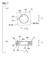
- the engaging portions 31 and 31 are formed by the through-hole 32 formed in the bracket member 3, as shown in FIG. 3 , it is not necessary to form the engaging portion 31 by using the through-hole in the present invention, for example, the engaging portion may be formed by using a non-penetrating hole, or an engaging portion 131 may be formed by using a cut portion 132 extending from the inner circumferential surface 30a of the fixing hole 30 of the bracket member 3 to the outside in the radial direction, as shown in FIG 7 .
- the positioning portion 24 is provided on each of the outer tubes 20 and 20 of the pair of damping rubbers 2A and 2B, and the engaging portion 31 is formed on each of the upper and lower surfaces 3a and 3b of the bracket member 3, the positioning portion 24 may be formed on any one of the pair of damping rubbers 2A and 2B in the present invention.
- the mold cavity portions 26A and 26B are provided on only one damping rubber 2A and the mold cavity portions 26A and 26B are not provided on the other damping rubber 2B, it is not necessary to determine the circumferential position of the other damping rubber 2B with respect to the bracket member 3, and the positioning portion 24 may not be formed on the outer tube 20 of the other damping rubber 2B. In this case, it is not necessary to form the engaging portion 31 on the lower surface 3b of the bracket member 3 opposite to the flange portion 23 of the outer tube 20 of the other damping rubber 2B.
- the positioning portion 24 may be formed on any one of the pair of damping rubbers 2A and 2B, if a damping rubber positioning portion 27 for determining the relative circumferential position between the pair of the damping rubbers 2A and 2B is formed between the pair of damping rubbers 2A and 2B.
- the damping rubber positioning portion 27 is composed of a convex portion 28 and a concave portion 29 which are fitted to each other.
- the convex portion 28 is formed on the axial inner end of the inner tube 21 of one damping rubber 2A, while the concave portion 29 is formed on the axial inner end of the inner tube 21 of the other damping rubber 2B.
- the convex portion 28 or the concave portion 29 may be formed on the outer tubes 20 and 20 of the pair of damping rubbers 2A and 2B.
- the positioning portion 24 is only provided on the outer tube 20 of one damping rubber 2A and the positioning portion 24 is not provided on the outer tube 20 of the other damping rubber 2B, the circumferential position of the other damping rubber 2B is determined with respect to the bracket member 3. Accordingly, it is possible to dispose the mold cavity portions 26A and 26B provided on the other damping rubber 2B in line with the vibrating direction.
- the positioning portion 24 protrudes from the inner surface 23 a of the flange portion 23 of the outer tube 20
- the positioning portion of the present invention is not limited thereto.
- the positioning portion 124 may be formed by bending the boss 23c inwardly in the axial direction, the boss protruding from the outer circumference edge of the flange portion 23 to the outside in the radial direction. This allows the positioning portion 124 to be easily formed.
- a flange portion 123 may have a proximal end rounded towards the axial outside. This can prevent interference between a curved portion 123d of the proximal end of the flange portion 23 and the corner of the fixing hole 30 of the bracket 3, and it is possible to omit the chamfering process for the corner of the fixing hole 30.
- a positioning portion 224 may be provided on the outer circumferential surface 20b of the outer tube 20.
- the bracket member 3 is formed with the engaging portion 131 formed by the cut portion 132 shown in FIG 7 , and the positioning portion 224 is engaged with the engaging portion 131.
- the outer tube 20 and the inner tube 21 are disposed on the same axis, the outer tube 20 and the inner tube 21 may be eccentrically disposed.
- the rubber elastic body 22 is provided with two symmetrical mold cavity portions 26A and 26B, with the inner tube 21 being interposed between the mold cavity portions 26A and 26B, the mold cavity portion may be formed on only the inner tube 21 in any one of the left and right directions.
- damping rubbers 2A and 2B having the same configuration are assembled as the pair of damping rubbers 2A and 2B
- damping rubbers 2A and 2B having different configuration may be assembled as the pair of damping rubbers 2A and 2B.
- damping rubbers may be assembled, in which the shape or material of the outer tube 20 or the inner tube 21 is different or the shape or material of the rubber elastic body 22 is different.
- the placement position or shape of the mold cavity portion of one damping rubber 2A and the mold cavity portion of the other damping rubber 2B may be different.
- the mold cavity portion may be formed in one damping rubber 2A only in one of the left and right directions, and the mold cavity portion may be formed in the other damping rubber 2B only in the other of the left and right directions.
- the bracket member 3 is provided with the engaging portion 31 and the positioning portion 24 is engaged with the engaging portion 31, the present invention may employ a configuration in which the bracket member 3 is not provided with the engaging portion 31.
- the positioning portion may be an eye mark for aligning the position visually.
- the bracket member 3 may be provided with a mark for aligning a position, without requiring an engaging portion such as the engaging portion 31.
- one positioning portion 24 is provided for one outer tube 20
- a plurality of positioning portions 24 may be provided for one outer tube 20.
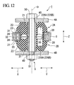
- the mold cavity portions 26A and 26B are axially penetrated, as shown in FIG. 12
- mold cavity portions 226A and 226B with a non-through hole extending in the axial direction may be used.
- components in the above-mentioned embodiment may be properly displaced with components known in the art, without departing from the scope of the claimed invention, and the above-mentioned alternative embodiments may be properly combined.
- the outer tubes of the damping rubbers are inserted into the fixing holes of the bracket member in the non-pressing state, and in order to dispose the position of the mold cavity portion in line with the vibrating direction of the vibration generating body, the circumferential position of the damping rubbers is determined with respect to the bracket member by the positioning portion. Therefore, it is possible to improve the vibration-resistance properties of the damping rubbers, while ensuring the support rigidity of the damping rubbers. Also, it is possible to easily assemble the vibration control equipment, and thus lower the production cost.
Landscapes
- Engineering & Computer Science (AREA)
- General Engineering & Computer Science (AREA)
- Mechanical Engineering (AREA)
- Springs (AREA)
- Vibration Prevention Devices (AREA)
Abstract
Description
- The present invention relates to a vibration control equipment for use in a cabin mount or engine mount of machines for agriculture or construction.
The present application claims priority from Japanese Patent Application No.2007-095292, filed on March 30, 2007 - In general, when a vibration generating body, such as an engine, is mounted on a vibration receiving body, such as a vehicle body, a vibration control equipment is interposed between the vibration generating body and the vibration receiving body so as to prevent or suppress vibration from being transmitted from the vibration generating body to the vibration receiving body. As such a vibration control equipment, there is a sandwich-type vibration control equipment including a pair of damping rubbers and plate members placed on both sides of the damping rubbers. Each of the damping rubbers is composed of an outer tube formed substantially in the shape of a cylinder and has a flange portion formed at an axial outer end portion, an inner tube substantially in the shape of a cylinder disposed in the inside of the outer tube, and a rubber elastic body interposed between the outer tube and the inner tube. The pair of damping rubbers is connected to each other by abutting the axial inner ends thereof, so that the damping rubbers are axially clamped at the outside thereof by means of the pair of plate members. Also, the pair of plate members is connected to each other by means of fastening members, such as bolts, penetrating through the inside of the pair of inner tubes (e.g., see Patent Document 1).
- With the sandwich-type vibration control equipment constructed as described above, as the stiffness of the damping rubber is lowered, the vibration-resistance properties are enhanced. However, there is a problem that if the support rigidity of the damping rubbers is lowered too much, the vibration generating body interferes with surrounding objects. Consequently, a technique of forming mold cavity portions in a rubber elastic body has been proposed in order to improve the vibration-resistance properties of the damping rubbers, as well as ensuring the support rigidity of the damping rubbers. In the damping rubber having the mold cavity portions, since the rigidity is lowered only in the arranging direction of the mold cavity portions, the vibration-resistance performance thereof is different in the vibration input direction. According to this technique, since the rigidity in the direction of the vibration transmitted from the vibration generating body can be set lower, it can ensure the support rigidity and thus improve the vibration-resistance properties (e.g., see Patent Document 2).
- For example, in the case where the vibration control equipment is installed on the vehicle body through a bracket member and the plate member of the vibration control equipment is fixed to a lower portion of the engine, the vibration transmitted from the engine to the vibration control equipment causes rolling vibration to be generated around a driving shaft of the engine. In this instance, the mold cavity portions are disposed in a planar rolling direction, that is, a right and left direction (a horizontal direction perpendicular to an engine shaft), so that the damping rubbers are positioned in a circumferential direction. This will help to ensure the support rigidity and improve the vibration-resistance properties, while the rigidity is maintained intact in an upward and downward direction (an axial direction of the damping rubbers) and a front and rear direction (a direction in parallel with the engine shaft) but the rigidity is lowered in the left and right direction.
- [Patent Document 1] Japanese Unexamined Utility Model Application, First Publication No.
S59-191452 - [Patent Document 2] Japanese Unexamined Patent Application, First Publication No.
2000-193003 - According to conventional vibration control equipment, however, the circumferential direction of the damping rubbers is fixed by pressing the damping rubbers into holes of substantially cylindrical shape formed in the bracket member when assembling, with the circumferential direction of the damping rubbers being fixed. For this reason, there is a problem that the assembling work is complicated. Also, there is another problem that the production cost is increased since the press fitting process requires jigs for the press fitting.
- Therefore, the present invention has been made to solve the above-mentioned problems occurring in the prior art, and an object of the present invention is to provide a vibration control equipment which can dispose a mold cavity portion in line with a vibrating direction and can be easily assembled to reduce the production cost.
- The vibration control equipment according to the present invention including a pair of damping rubbers each having an outer tube, an axial outer end of the outer tube being provided with a flange portion extending outwardly in a radial direction, an inner tube disposed in the outer tube, and a rubber elastic body for connecting the outer tube and the inner tube, the damping rubbers being symmetrically disposed in a vertical direction; a pair of plate members, with the pair of damping rubbers being interposed between the pair of plate members; a bracket member interposed between the upper and lower flange portions of the pair of damping rubbers, and provided with a fixing hole, through which each outer tube of the pair of damping rubbers is inserted from an upper portion and a lower portion; and a fastening member that connects the pair of plate members. In the vibration control equipment, the bracket member is fixed to any one of a vibration generating body and a vibration receiving body, at least one of the pair of plate members is fixed to the other of the vibration generating body and the vibration receiving body, and the rubber elastic bodies are axially compressed through the pair of plate members by firmly fastening the fastening member. In the vibration control equipment, before the fastening member is firmly fastened, the outer tube has an outer diameter smaller than an inner diameter of the fixing hole; the rubber elastic bodies are compressively deformed by firmly fastening the fastening member, so that the flange portion comes into close contact with the bracket member to clamp the bracket member by the upper and lower flange portions; at least any one of the pair of rubber elastic bodies is provided with a mold cavity portion; and at least one of the pair of outer tubes is provided with a positioning portion for determining circumferential positions of the pair of damping rubbers with respect to the bracket member.
- With the above characteristics, the pair of damping rubbers are disposed on and under the bracket member, and the outer tube of one damping rubber is inserted into the fixing hole of the bracket member from the upper side of the bracket member. The outer tube of the other damping rubbers is inserted into the fixing hole of the bracket member from the lower side of the bracket member. In this instance, the outer tubes have an outer diameter smaller than the inner diameter of the fixing hole, and a clearance is formed between the outer circumferential surface of the outer tube and the inner circumferential surface of the fixing hole. That is, the outer tubes are inserted into the fixing holes in a non-pressing state. Also, when the outer tubes are inserted into the fixing hole, in order to dispose the mold cavity portions in line with the vibrating direction of the vibration generating body, each circumferential position of the damping rubbers is determined with respect to the bracket member by the positioning portion. The plate members are disposed on and under the pair of damping rubbers, and the upper and lower plate members are connected to each other by means of the fastening member penetrating the inside of the inner tube. As the fastening member is fastened, the pair of damping rubbers is vertically pressed by the pair of plate members. Therefore, the axial inner ends of the pair of opposite inner tubes come into contact with each other. Also, as the fastening member is fastened, the rubber elastic body is axially compressed, and then is elastically deformed in such a way that it is radially expanded to the outside. Therefore, the flange portions of the outer tubes connected to the rubber elastic body come into close contact with the bracket member, and the bracket member is clamped between the upper and lower flange portions, so that the pair of the damping rubbers is fixed to the bracket member.
- Also, in the vibration control equipment according to the present invention, the bracket member may be provided with an engaging portion which is engaged with the positioning portion.
- With the above configuration, when the outer tube of the damping rubber is inserted into the fixing hole of the bracket member, the positioning portion provided on the outer tube is engaged with the engaging portion provided on the bracket portion, so that the circumferential position of the damping rubbers is determined with respect to the bracket member.
- Also, in the vibration control equipment according to the present invention, the positioning portion may be provided on the flange portion.
- With the above configuration, it is possible to easily manufacture the outer tube as compared with the case where the outer circumferential surface of the outer tube is provided with the positioning portion. Also, in the case that the bracket member is provided with the engaging portion, the engaging portion is provided on the upper surface or lower surface of the bracket member opposite to the flange portion of the outer tube, so that it is possible to easily manufacture the bracket member as compared with the case where the engaging portion is formed on the inner circumferential surface of the fixing hole.
- Also, in the vibration control equipment according to the present invention, the pair of the outer tubes may be provided with the positioning portion.
- With the above configuration, the circumferential position of one damping rubber and the circumferential position of the other damping rubber are respectively determined by the positioning portion, so that the mold cavity portion provided on one damping rubber and the mold cavity portion provided on the other damping rubber are respectively disposed in line with the vibrating direction of the vibration generating body.
- Also, in the vibration control equipment according to the present invention, a damping rubber positioning portion may be provided between the pair of damping rubbers to determine the relative circumferential position between the pair of damping rubbers.
- With the above configuration, when the outer tubes of the pair of damping rubbers are each inserted into the fixing holes, the relative circumferential position between one damping rubber and the other damping rubber is determined by the damping rubber positioning portion, and there is no position difference between the pair of damping rubbers. Therefore, if the circumferential position of one damping rubber is determined with respect to the bracket member, the circumferential position of the other damping rubber is determined with respect to the bracket. For example, in the case where the positioning portion is provided on the outer tube of one damping rubber and the positioning portion is not provided on the outer tube of the other damping rubber, if there is the damping rubber positioning portion, the circumferential position of the other damping rubber is determined with respect to the bracket member, so that it is possible to dispose the mold cavity portion provided on the other damping rubber in line with the vibrating direction.
- Also, in the vibration control equipment according to the present invention, one of the pair of damping rubbers having the mold cavity portion may include an outer tube side segment body, in which an outer circumferential portion of the rubber elastic body is attached to the outer tube, and an inner tube side segment body, in which an inner circumferential portion of the rubber elastic body is attached to the inner tube to form the mold cavity portion.
- With the above configuration, it is possible to easily form the rubber elastic body, and defects, such as hollows or cracks, are hardly formed in the rubber elastic body as compared with the case of manufacturing the damping rubber by connecting the rubber elastic body between the outer tube and the inner tube. Further, it is possible to easily form the mold cavity portion.
- In addition, in the vibration control equipment according to the present invention, a segment body positioning portion may be provided between the segment bodies to determine the relative circumferential position between the segment bodies.
- With the above configuration, the relative circumferential position between the pair of segment bodies is determined by the segment body positioning portion, and there is no position difference between the segment bodies. Therefore, if the circumferential position of the outer tube side segment body is determined by the positioning portion provided on the outer tube, the position of the other segment body assembled to the outer tube side segment body is determined, and the mold cavity portion provided on the inner tube side segment body is disposed in line with the vibrating direction.
- Also, in the vibration control equipment according to the invention, the mold cavity portion may be axially penetrated.
- With the above configuration, it is possible to easily form the mold cavity portions as compared with the damping rubber having a non-penetrating mold cavity portion. Also, it is possible to easily set the property of the damping rubbers as compared with the damping rubber with non-penetrating mold cavity portion.
- Also, in the vibration control equipment according to the present invention, the mold cavity portion may be a non-penetrating hole extending axially.
- With the above configuration, even though the non-penetrating mold cavity portion is provided, the spring stiffness of the mold cavity portion in the displacement direction is lowered as compared with the direction in which the mold cavity portion is not formed, which is effective.
- With the vibration control equipment according to the present invention, the outer tubes of the damping rubbers are inserted into the fixing holes of the bracket member in the non-pressing state, and in order to dispose the position of the mold cavity portion in line with the vibrating direction of the vibration generating body, the circumferential position of the damping rubbers is determined with respect to the bracket member by the positioning portion. Therefore, it is possible to improve the vibration-resistance properties of the damping rubbers, while ensuring the support rigidity of the damping rubbers. Also, it is possible to easily assemble the vibration control equipment, and thus lower the production cost.
-
-
FIG 1 is a cross-sectional view of the vibration control equipment to explain a first embodiment of the present invention. -
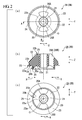
FIG 2 is a view showing a damping rubber to explain the first embodiment of the present invention, in which (a) is a plan view, (b) is a cross-sectional view, and (c) is a plan view. -
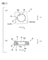
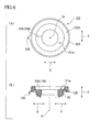
FIG 3 is a view showing a bracket member to explain the first embodiment of the invention, in which (a) is a plan view, and (b) is a cross-sectional view. -
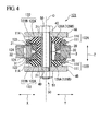
FIG 4 is a cross-sectional view of vibration control equipment to explain a second embodiment of the present invention. -
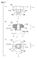
FIG 5 is a view showing an inner tube side segment body to explain the second embodiment of the present invention, in which (a) is a side view, (b) is a cross-sectional view, and (c) is a plan view. -
FIG 6 is a view showing an outer tube side segment body to explain the second embodiment of the present invention, in which (a) is a plan view, and (b) is a cross-sectional view. -
FIG 7 a view showing a bracket member to explain another embodiment of the present invention, in which (a) is a plan view, and (b) is a cross-sectional view. -
FIG 8 is a cross-sectional view of a pair of damping rubbers to explain another embodiment of the present invention. -
FIG 9 is a partially enlarged view showing a positioning portion to explain another embodiment of the present invention, in which (a) is a cross-sectional view, and (b) is a plan view. -
FIG 10 is a partially enlarged view showing a flange portion to explain another embodiment of the present invention, in which (a) is a cross-sectional view, and (b) is a plan view. -
FIG. 11 is a partially enlarged view showing a positioning portion to explain another embodiment of the present invention, in which (a) is a cross-sectional view, and (b) is a plan view. -
FIG 12 is a cross-sectional view of vibration control equipment to explain another embodiment of the present invention. -
- 1, 101: VIBRATION CONTROL EQUIPMENT
- 2A, 2B: DAMPING RUBBER
- 3: BRACKET MEMBER
- 4A, 4B: A PAIR OF PLATE MEMBERS
- 5: FASTENING MEMBER
- 20: OUTER TUBE
- 21: INNER TUBE
- 22, 122: RUBBER ELASTIC BODY
- 23, 123: FLANGE PORTION
- 24, 124, 224: POSITIONING PORTION
- 26A, 26B, 126A, 126B, 226A, 226B: MOLD CAVITY PORTION
- 27: DAMPING RUBBER POSITIONING PORTION
- 30: FIXING HOLE
- 31, 131: ENGAGING PORTION
- 114: SEGMENT BODY POSITIONING PORTION
- A vibration control equipment according to first and second embodiments of the present invention will now be described with reference to the accompanying drawings.
- First of all, a vibration control equipment 1 according to the first embodiment will now be described with reference to
FIGs. 1 to 3 .
In the description below, the direction (horizontal direction) denoted by the symbol X shown in the figure is referred to as the front and rear direction, the direction (the vertical direction) denoted by the symbol Y shown in the figure is referred to as the left and right direction, and the direction (the vertical direction) denoted by the symbol Z shown in the figure is referred to as the upward and downward direction. Also, when viewing from one dampingrubber 2A (2B), an opposite surface side (a lower side in (b) ofFIG 2 ) facing the other dampingrubber 2B (2A) is referred to as an axial inner side, and a side (an upper side in (b) ofFIG 2 ) opposite to the surface is referred to as an axial outer side. -
-
FIG 1 is a cross-sectional view of a vibration control equipment 1 according to the first embodiment of the present invention. -
FIG 2 is a view showing the dampingrubber 2A (2B) to which an external force is not applied. (a) ofFIG 2 is a plan view when viewing from an axial outer side, (b) pfFIG 2 is a cross-sectional view taken along the line A-O-B shown in (a) ofFIG 2 , and (c) ofFIG 2 is a plan view when viewing from an axial inner side. -
FIG 3 is a view showing abracket member 3. (a) ofFIG 3 is a plan view, and (b) ofFIG 3 is a cross-sectional view. - As shown in
FIG 1 , the vibration control equipment 1 is applied as, for example, an engine mount for damping and absorbing vibration input from an engine (a vibration generating body), which is not shown, mounted on, for example, a construction machine, to suppress the vibration from being transmitted to a vehicle body (a vibration receiving body), which is not shown. The vibration of the engine is rolling vibration caused by a rotation around a driving shaft thereof, and the vibration control equipment damps and absorbs the rolling vibration. The driving shaft of the engine which is not shown is extended in the front and rear direction, but the vibrating direction of the engine is the left and right direction in planar view. - The vibration control equipment 1 includes the pair of damping
rubbers bracket member 3, a pair ofplate members fastening member 5. - The construction of the damping
rubber 2A (2B) will now be described.
As shown inFIG 2 , the dampingrubber 2A (2B) includes anouter tube 20 of substantially cylindrical shape, aninner tube 21 of substantially cylindrical shape which has a diameter smaller than that of theouter tube 20, is disposed in theouter tube 20, and is spaced apart from the outer tube, and a rubberelastic body 22 interposed between theouter tube 20 and theinner tube 21. - The
outer tube 20 is provided at the axial outer end portion thereof with aflange portion 23 straightly protruding to the outside in a radial direction. Theflange portion 23 is extended along the entire circumference of theouter tube 20.
Theflange portion 23 is provided with apositioning portion 24 for determining circumferential positions of the dampingrubbers bracket member 3 so thatmold cavity portions portion 24 is a pin-shaped convex portion protruding toward aninner surface 23a of the axial inner side of theflange portion 23, and is engaged with an engagingportion 31 described below. The positioningportion 24 is provided on each pair of upper and lowerouter tubes - The
inner tube 21 is concentrically disposed in theouter tube 20, and has a whole length longer than that of theouter tube 20 so that theinner tube 21 protrudes from theouter tube 20 to the outside in the axial direction. Also, in the case where an external force is not applied, the end surface of the axial inner side of theinner tube 21 is placed at the axial outer side rather than the end surface of the axial inner side of theouter tube 20. - The rubber
elastic body 22 is adapted to resiliently connect theouter tube 20 with theinner tube 21, and is cure-adhered to the innercircumferential surface 20a of theouter tube 20 and the axialouter surface 23b of theflange portion 23 and also cure-adhered to the outer circumferential surface 21a of theinner tube 21. The rubberelastic body 22 is formed in the shape of taper, of which the diameter is gradually decreased towards the axial outer side, and theend surface 22a of the axial inner side of the rubberelastic body 22 is formed in a concave shape as a curved portion. The rubberelastic body 22 is provided in theend surface 22b of the axial outer side with agroove 25 extending in a circumferential direction along the entire circumference, the groove being formed in a U shape of a cross section. - The rubber
elastic body 22 is provided with themold cavity portions rubbers mold cavity portions elastic body 22, and are through-holes extending in the axial direction. Themold cavity portions inner tube 21 being interposed therebetween in the radial direction. Themold cavity portions portion 24 around the central axis O by 90° in a plan view of the dampingrubbers - The damping
rubbers FIG. 1 , in such a way that one dampingrubber 2A is disposed vertically symmetrically with the other dampingrubber 2B. In other words, the pair of dampingrubbers - As shown in
FIG 3 , thebracket member 3 is a thick plate member, and is fixed and substantially horizontally installed to any one of the engine and the vehicle body (not shown). Thebracket member 3 is provided with a substantiallycircular fixing hole 30. As shown inFIGs. 1 to 3 , each of theouter tubes rubbers hole 30. Upper andlower corners hole 30 are each chamfered over the entire circumference thereof. - The peripheral portion of the fixing
hole 30 formed in thebracket member 3 is disposed between the upper andlower flange portions rubbers lower flange portions
An engagingportion 31 which is engaged with thepositioning portion 24 is formed at the peripheral portion of the fixinghole 30 formed in thebracket member 3. The engagingportion 31 has a through-hole 32 vertically penetrating thebracket member 3, and is formed in both the upper andlower surfaces bracket member 3. A planar position of the engagingportion 31 is set so that themold cavity portions positioning portion 24 is engaged with the engagingportion 31. More specifically, the engagingportion 31 is formed at the position of the front and rear sides with respect to the central axis O. - As shown in
FIG 1 , the pair ofplate members rubbers rubbers plate members bracket member 3 is fixed to the engine, theplate members bracket member 3 is fixed to the vehicle body, theplate members plate members bolt hole 40 through which abolt 50 described below passes. Thebolt hole 40 communicates with theinner tube 21. - The
fastening member 5 is adapted to connect the pair ofplate members bolt 50 and anut 51. Thebolt 50 is inserted into thebolt hole 40 of oneplate member 4A from the axial outer side (the upper side inFIG 1 ) of theplate member 4A, and passes the pair of upper and lowerinner tubes bolt hole 40 of theother plate member 4B to protrude from the axial outer side (the lower side inFIG. 1 ) of theplate member 4B. A tip of thebolt 50 protruding from thebolt hole 40 of theother plate member 4B is threadably engaged with thenut 51. - The above-mentioned vibration control equipment 1 is assembled as mentioned below.
First, in order to interpose thebracket member 3 between the pair of the dampingrubbers rubbers bracket member 3, and theouter tube 20 of one dampingrubber 2A is inserted into the fixinghole 30 of thebracket member 3 from the upper side of thebracket member 3. Theouter tube 20 of the other dampingrubbers 2B is inserted into the fixinghole 30 of thebracket member 3 from the lower side of thebracket member 3. In this instance, theouter tubes hole 30, and a clearance (approximately 0.2 to 1.3 mm) is formed to some extent between an outercircumferential surfaces 20b of theouter tubes circumferential surface 30a of the fixinghole 30. That is, theouter tubes - When the
outer tubes hole 30, in order to dispose themold cavity portions rubbers bracket member 3 by the positioningportion 24. More specifically, the positioningportion 24 is inserted into the engagingportion 31 formed in thebracket member 3. Since the engagingportion 31 is formed at the front and rear sides with respect to the central axis O, the positioningportion 24 is positioned at the front and rear sides with respect to the central axis O. Also, sincemold cavity portions portion 24 around the central axis O by 90° in a plan view of the dampingrubbers mold cavity portions mold cavity portions - Next, the pair of
plate members rubbers rubbers plate members
Thebolt 50 is inserted into thebolt hole 40 of oneplate member 4A to pass through the pair of theinner tubes bolt 50 protrudes from thebolt hole 40 of theother plate member 4B and is threadably engaged with thenut 51. This allows the pair ofplate members - To continue, the
bolt 50 or thenut 51 is rotated to fasten thefastening member 5. As thefastening member 5 is fastened, the interval between the pair ofplate members rubbers plate members inner tube 21 is axially pushed to the inside, and the axial inner end surface of theinner tube 21 protrudes into the axial inner side rather than the end surface of the axial inner side of theouter tube 20, so that the opposing axial inner ends of the pair of upper and lowerinner tubes elastic body 22 is preliminarily compressed in the axial direction, and thus is elastically deformed in such a way that it is radially expanded to the outside. This causes theinner surfaces flange portions outer tubes lower surfaces bracket member 3, and thebracket member 3 is clamped between the upper andlower flange portions rubbers bracket member 3.
With the above processes, the assembly of the vibration control equipment 1 is completed. - In the vibration control equipment 1 according to the first embodiment, since the
mold cavity portions rubbers rubbers mold cavity portions rubbers rubbers elastic body 22 is provided with themold cavity portions rubbers rubbers - A test confirming the effect will now be described. This test was carried out by comparing the case where an engine was driven by using a vibration control equipment having no mold cavity portion with the case where an engine was driven by using the vibration control equipment having the mold cavity portions. The vibration control equipment having the same configuration was utilized in this test, except for the mold cavity portions. The vibration control equipment having no mold cavity portion had a static spring constant of 1200 (N/mm) in a front and rear direction, 1200 (N/mm) in a left and right direction, and 1450 (N/mm) in an upward and downward direction. Meanwhile, the vibration control equipment having the mold cavity portions in the left and right direction had a static spring constant of 1200 (N/mm) in a front and rear direction, 725 (N/mm) in a left and right direction, and 1450 (N/mm) in an upward and downward direction. When the vibration test using both above-mentioned vibration control equipment was carried out under the same conditions, the vibration control equipment having no mold cavity portion had the natural vibration frequency of 21.5 (Hz) in the rolling direction of the engine, while the vibration control equipment having the mold cavity portions had the natural vibration frequency of 18.1 (Hz) in the rolling direction of the engine, which is lower than that of the vibration control equipment having no mold cavity portions. As a result, the vibration transmissibility of the vibration control equipment having no mold cavity portion was 20%, while the vibration transmissibility of the vibration control equipment having the mold cavity portions was 14%. The vibration transmissibility was lowered as compared with that of the vibration control equipment having no mold cavity portion. It is apparent from the above test result that the vibration-resistance properties were improved by the mold cavity portions.
- With the vibration control equipment 1 according to the first embodiment, the circumferential positions of the damping
rubbers bracket member 3 are determined by the positioningportion 24, so that the positions of themold cavity portions outer tubes rubbers bracket member 3 in a non-pressing state. As a result, since the complicated process of press-fitting theouter tube 20 is not required, it is possible to easily assemble the vibration control equipment 1. Also, since the press fitting process is not carried out, jigs or the like are not required for the press fitting process, and thus the production cost is significantly reduced. - Also, since the
bracket member 3 is provided with the engagingportion 31 which is engaged with thepositioning portion 24, it is possible to easily and reliably determine the circumferential position of the dampingrubbers portion 31 with thepositioning portion 24 when positioning. - Since the
positioning portion 24 is formed on theflange portion 23 of theouter tube 20, it is possible to easily manufacture theouter tube 20 as compared with the case where thepositioning portion 24 is formed on the outercircumferential surface 20b of theouter tube 20.
Also, since the engagingportion 31 engaging with thepositioning portion 24 is provided on the upper andlower surfaces bracket member 3 opposite to theflange portion 3 of theouter tube 20, it is possible to easily manufacture thebracket member 3 as compared with the case where the engaging portion is formed on the innercircumferential surface 30a of the fixinghole 30. Therefore, it is possible to reduce the production cost for components. - The pair of upper and lower
outer tubes positioning portions 24, respectively, and thebracket member 3 is provided with the through-hole 32 penetrating vertically thebracket member 3. Since the engagingportion 31 is formed on the upper andlower surfaces bracket member 3 by the through-hole 32, when the pair of dampingrubbers bracket member 3, the pair of the dampingrubbers portion 24. This allows themold cavity portions rubber 2A and themold cavity portions rubber 2B to dispose in line with the vibrating direction of the engine. - Further, since the
mold cavity portions mold cavity portions rubbers rubbers mold cavity portions - Next, a
vibration control equipment 101 according to a second embodiment of the present invention will now be described. Like parts are designated by the same reference numerals as the first embodiment, and the description thereof will be omitted herein. -
-
FIG 4 is a cross-sectional view of thevibration control equipment 101 according to the second embodiment. -
FIG 5 is a view showing an inner tubeside segment body 110, in which (a) ofFIG. 5 is a side view, (b) ofFIG 5 is a cross-sectional view, and (c) ofFIG 5 is a plan view when viewing at the axial inner side. -
FIG 6 is a view showing an outer tubeside segment body 111, in which (a) ofFIG 6 is a plan view when viewing from the axial outer side, and (b) ofFIG. 6 is a cross-sectional view. - The
outer tube 20 and theinner tube 21 are connected to each other by one rubberelastic body 22 in the first embodiment, but dampingrubbers segment bodies vibration control equipment 101 according to the second embodiment shown inFIG 4 . - More specifically, the damping
rubbers side segment body 110 shown inFIG 5 with an outer tubeside segment body 111 shown inFIG. 6 .
The dampingrubbers - As shown in
FIGs. 4 and5 , the inner tubeside segment body 110 is formed by attaching an innercircumferential portion 122A of a rubberelastic body 122 to theinner tube 21. The inner tubeside segment body 110 is formed in a shape of headed bolt, and is composed of ahead portion 112 of which a rubber portion of an axial outer side is enlarged, and aleg portion 113 of which an axial inner side is formed in a cylindrical shape. In the inner tubeside segment body 110, both radial portions of theleg portion 113 are cut in an axial direction to form non-penetratingmold cavity portions - As shown in
FIGs. 4 and6 , the outer tubeside segment body 111 is formed by attaching an outercircumferential portion 122B of the rubberelastic body 122 to theouter tube 20. The outer tubeside segment body 111 has a stepped inner circumferential surface, so that thehead portion 112 and theleg portion 113 of the inner tubeside segment body 110 are separately fitted. - A segment
body positioning portion 114 for determining a relative circumferential position between the inner tubeside segment body 110 and the outer tubeside segment body 111 is provided between the inner tubeside segment body 110 and the outer tubeside segment body 111. The segmentbody positioning portion 114 is composed of aconvex portion 115 and aconcave portion 116 which are fitted to each other. Theconvex portion 115 is formed on aninner surface 112a on the axial inner side of thehead portion 112 of the inner tubeside segment body 110, and theconcave portion 116 is formed on the steppedsurface 111a on the inner circumferential surface of the outer tubeside segment body 111. Theconcave portion 116 may be formed on the inner tubeside segment body 110, and theconvex portion 115 may be formed on the outer tubeside segment body 111. - The
vibration control equipment 101 according to the second embodiment achieves the following effect, in addition to the effect obtained in the first embodiment.
Namely, with thevibration control equipment 101 according to the second embodiment, it is possible to easily form the rubberelastic body 122, and defects, such as hollows or cracks, are hardly formed in the rubberelastic body 122 as compared with the first embodiment in which the damping rubber is formed in single part. This can improve the quality of thevibration control equipment 101. - Also, since the segment
body positioning portion 114 is provided between the pair of the inner tubeside segment body 110 and the outer tubeside segment body 111 which are assembled, the relative circumferential position between the inner tubeside segment body 110 and the outer tubeside segment body 111 is determined by the segmentbody positioning portion 114, and there is no positional difference between the inner tubeside segment body 110 and the outer tubeside segment body 111. Therefore, if the circumferential position of the outer tubeside segment body 111 is determined with respect to thebracket member 3 by apositioning portion 124 provided on theouter tube 20, the position of the inner tubeside segment body 110 assembled to the outer tubeside segment body 111 is determined. Accordingly, themold cavity portions side segment body 110 are disposed in line with the vibrating direction. - The fitting portion of the inner tube
side segment body 110 and the outer tubeside segment body 111 is formed in a rectangular shape, so that it is possible to determine the relative position of the circumferential direction between the inner tubeside segment body 110 and the outer tubeside segment body 111. It is possible to determine the relative positions of the circumferential direction between the inner tubeside segment body 110 and the outer tubeside segment body 111 by pressing the inner tubeside segment body 110 into the inner circumference of the outer tubeside segment body 111. In this case, the segmentbody positioning portion 114 may be omitted. - Although the vibration control equipment according to the first and second embodiments of the present invention is described, the present invention is not limited thereto, and can be properly modified without deviating from the scope of the claimed invention.
For example, according to the above-mentioned embodiments, although the engagingportions hole 32 formed in thebracket member 3, as shown inFIG. 3 , it is not necessary to form the engagingportion 31 by using the through-hole in the present invention, for example, the engaging portion may be formed by using a non-penetrating hole, or an engagingportion 131 may be formed by using acut portion 132 extending from the innercircumferential surface 30a of the fixinghole 30 of thebracket member 3 to the outside in the radial direction, as shown inFIG 7 . - In addition, in these embodiments, although the
positioning portion 24 is provided on each of theouter tubes rubbers portion 31 is formed on each of the upper andlower surfaces bracket member 3, the positioningportion 24 may be formed on any one of the pair of dampingrubbers mold cavity portions rubber 2A and themold cavity portions rubber 2B, it is not necessary to determine the circumferential position of the other dampingrubber 2B with respect to thebracket member 3, and thepositioning portion 24 may not be formed on theouter tube 20 of the other dampingrubber 2B. In this case, it is not necessary to form the engagingportion 31 on thelower surface 3b of thebracket member 3 opposite to theflange portion 23 of theouter tube 20 of the other dampingrubber 2B. - In the case where the pair of damping
rubbers mold cavity portions FIG 8 , the positioningportion 24 may be formed on any one of the pair of dampingrubbers rubber positioning portion 27 for determining the relative circumferential position between the pair of the dampingrubbers rubbers rubber positioning portion 27 is composed of aconvex portion 28 and aconcave portion 29 which are fitted to each other. Theconvex portion 28 is formed on the axial inner end of theinner tube 21 of one dampingrubber 2A, while theconcave portion 29 is formed on the axial inner end of theinner tube 21 of the other dampingrubber 2B. Theconvex portion 28 or theconcave portion 29 may be formed on theouter tubes rubbers
Although thepositioning portion 24 is only provided on theouter tube 20 of one dampingrubber 2A and thepositioning portion 24 is not provided on theouter tube 20 of the other dampingrubber 2B, the circumferential position of the other dampingrubber 2B is determined with respect to thebracket member 3. Accordingly, it is possible to dispose themold cavity portions rubber 2B in line with the vibrating direction. - In the above-mentioned embodiments, although the pin-shaped
positioning portion 24 protrudes from theinner surface 23 a of theflange portion 23 of theouter tube 20, the positioning portion of the present invention is not limited thereto. For example, as shown inFIG. 9 , thepositioning portion 124 may be formed by bending theboss 23c inwardly in the axial direction, the boss protruding from the outer circumference edge of theflange portion 23 to the outside in the radial direction. This allows thepositioning portion 124 to be easily formed. - In the above-mentioned embodiments, although the
flange portion 23 straightly protrudes from the axial outer end of theouter tube 20 to the outside in a radial direction, as shown inFIG 10 , aflange portion 123 may have a proximal end rounded towards the axial outside. This can prevent interference between acurved portion 123d of the proximal end of theflange portion 23 and the corner of the fixinghole 30 of thebracket 3, and it is possible to omit the chamfering process for the corner of the fixinghole 30. - In the above-mentioned embodiments, although the
flange portion 23 is provided with thepositioning portion 24, the present invention is not limited to thepositioning portion 24 provided on theflange portion 23. For example, as shown inFIG 11 , apositioning portion 224 may be provided on the outercircumferential surface 20b of theouter tube 20. In this case, thebracket member 3 is formed with the engagingportion 131 formed by thecut portion 132 shown inFIG 7 , and thepositioning portion 224 is engaged with the engagingportion 131. - In the above-mentioned embodiments, although the
outer tube 20 and theinner tube 21 are disposed on the same axis, theouter tube 20 and theinner tube 21 may be eccentrically disposed.
Also, in the above-mentioned embodiments, although the rubberelastic body 22 is provided with two symmetricalmold cavity portions inner tube 21 being interposed between themold cavity portions inner tube 21 in any one of the left and right directions. - In the above-mentioned embodiment, although the damping
rubbers rubbers rubbers rubbers outer tube 20 or theinner tube 21 is different or the shape or material of the rubberelastic body 22 is different. The placement position or shape of the mold cavity portion of one dampingrubber 2A and the mold cavity portion of the other dampingrubber 2B may be different. The mold cavity portion may be formed in one dampingrubber 2A only in one of the left and right directions, and the mold cavity portion may be formed in the other dampingrubber 2B only in the other of the left and right directions. - In the above-mentioned embodiment, although the
bracket member 3 is provided with the engagingportion 31 and thepositioning portion 24 is engaged with the engagingportion 31, the present invention may employ a configuration in which thebracket member 3 is not provided with the engagingportion 31. For example, the positioning portion may be an eye mark for aligning the position visually. In this case, thebracket member 3 may be provided with a mark for aligning a position, without requiring an engaging portion such as the engagingportion 31. - In the above-mentioned embodiment, although one
positioning portion 24 is provided for oneouter tube 20, a plurality ofpositioning portions 24 may be provided for oneouter tube 20.
Also, in the above-mentioned embodiment, although themold cavity portions FIG. 12 ,mold cavity portions
In addition, components in the above-mentioned embodiment may be properly displaced with components known in the art, without departing from the scope of the claimed invention, and the above-mentioned alternative embodiments may be properly combined. - With the vibration control equipment according to the present invention, the outer tubes of the damping rubbers are inserted into the fixing holes of the bracket member in the non-pressing state, and in order to dispose the position of the mold cavity portion in line with the vibrating direction of the vibration generating body, the circumferential position of the damping rubbers is determined with respect to the bracket member by the positioning portion. Therefore, it is possible to improve the vibration-resistance properties of the damping rubbers, while ensuring the support rigidity of the damping rubbers. Also, it is possible to easily assemble the vibration control equipment, and thus lower the production cost.
Also, in
Claims (9)
- A vibration control equipment comprising:a pair of damping rubbers each having an outer tube, an axial outer end of the outer tube being provided with a flange portion extending outwardly in a radial direction, an inner tube disposed in the outer tube, and a rubber elastic body that connects the outer tube and the inner tube, the damping rubbers being symmetrically disposed in a vertical direction;a pair of plate members, with the pair of damping rubbers being interposed between the pair of plate members;a bracket member interposed between the upper and lower flange portions of the pair of damping rubbers, and provided with a fixing hole, through which each outer tube of the pair of damping rubbers is inserted from an upper portion and a lower portion; anda fastening member that connects the pair of plate members,wherein the bracket member is fixed to any one of a vibration generating body and a vibration receiving body, and at least one of the pair of plate members is fixed to the other of the vibration generating body and the vibration receiving body, andthe rubber elastic bodies are axially compressed through the pair of plate members by firmly fastening the fastening member, characterized in thatbefore the fastening member is firmly fastened, the outer tube has an outer diameter smaller than an inner diameter of the fixing hole;the rubber elastic bodies are compressively deformed by firmly fastening the fastening member, so that the flange portion comes into close contact with the bracket member to clamp the bracket member by the upper and lower flange portions;at least any one of the pair of rubber elastic bodies is provided with a mold cavity portion; andat least one of the pair of outer tubes is provided with a positioning portion that determines the circumferential positions of the pair of damping rubbers with respect to the bracket member.
- The vibration control equipment according to Claim 1, wherein the bracket member is provided with an engaging portion which is engaged with the positioning portion.
- The vibration control equipment according to Claim 1 or 2, wherein the positioning portion is provided on the flange portion.
- The vibration control equipment according to any one of Claims 1 to 3, wherein the pair of the outer tubes is provided with the positioning portion.
- The vibration control equipment according to any one of Claims 1 to 4, wherein a damping rubber positioning portion is provided between the pair of damping rubbers to determine a relative circumferential position between the pair of damping rubbers.
- The vibration control equipment according to any one of Claims 1 to 5, wherein one of the pair of damping rubbers having the mold cavity portion includes an outer tube side segment body, in which an outer circumferential portion of the rubber elastic body is attached to the outer tube, and an inner tube side segment body, in which an inner circumferential portion of the rubber elastic body is attached to the inner tube to form the mold cavity portion.
- The vibration control equipment according to Claim 6, wherein a segment body positioning portion is provided between the segment bodies to determine a relative circumferential position between the segment bodies.
- The vibration control equipment according to any one of Claims 1 to 7, wherein the mold cavity portion is axially penetrated.
- The vibration control equipment according to any one of Claims 1 to 7, wherein the mold cavity portion is a non-penetrating hole extending axially.
Applications Claiming Priority (2)
| Application Number | Priority Date | Filing Date | Title |
|---|---|---|---|
| JP2007095292A JP5225603B2 (en) | 2007-03-30 | 2007-03-30 | Vibration isolator |
| PCT/JP2008/056116 WO2008120728A1 (en) | 2007-03-30 | 2008-03-28 | Vibration control equipment |
Publications (3)
| Publication Number | Publication Date |
|---|---|
| EP2136102A1 true EP2136102A1 (en) | 2009-12-23 |
| EP2136102A4 EP2136102A4 (en) | 2012-06-13 |
| EP2136102B1 EP2136102B1 (en) | 2018-12-12 |
Family
ID=39808308
Family Applications (1)
| Application Number | Title | Priority Date | Filing Date |
|---|---|---|---|
| EP08739234.6A Not-in-force EP2136102B1 (en) | 2007-03-30 | 2008-03-28 | Vibration control equipment |
Country Status (5)
| Country | Link |
|---|---|
| US (1) | US8523154B2 (en) |
| EP (1) | EP2136102B1 (en) |
| JP (1) | JP5225603B2 (en) |
| CN (1) | CN101646880B (en) |
| WO (1) | WO2008120728A1 (en) |
Cited By (3)
| Publication number | Priority date | Publication date | Assignee | Title |
|---|---|---|---|---|
| EP2586653A1 (en) * | 2010-06-22 | 2013-05-01 | Toyota Boshoku Kabushiki Kaisha | Vehicle seat mounting structure |
| EP2532918A4 (en) * | 2010-02-04 | 2017-03-08 | Bridgestone Corporation | Vibration-damping device |
| EP2662591A4 (en) * | 2011-01-06 | 2018-01-24 | Toyo Tire & Rubber Co., Ltd. | Anti-vibration device |
Families Citing this family (14)
| Publication number | Priority date | Publication date | Assignee | Title |
|---|---|---|---|---|
| JP5313764B2 (en) * | 2009-05-13 | 2013-10-09 | 株式会社ブリヂストン | Vibration isolator |
| JP5798778B2 (en) * | 2011-04-05 | 2015-10-21 | 株式会社ブリヂストン | Vibration isolator |
| CN102514458B (en) * | 2011-12-23 | 2015-06-17 | 上汽通用五菱汽车股份有限公司 | Support rod mechanism, suspension control arm and automobile |
| JP5595458B2 (en) * | 2012-09-26 | 2014-09-24 | 東海ゴム工業株式会社 | Vibration isolator |
| JP6645930B2 (en) | 2016-08-09 | 2020-02-14 | アイシン精機株式会社 | Air pump device and seat device |
| US10458281B2 (en) * | 2017-06-12 | 2019-10-29 | United Technologies Corporation | Resilient mounting assembly for a turbine engine |
| US11078950B2 (en) * | 2018-02-26 | 2021-08-03 | Raytheon Company | Fastener biasing system |
| RU186458U1 (en) * | 2018-03-05 | 2019-01-21 | Николай Иванович Подлевский | VIBRATION ISOLATING SYSTEM |
| KR102452937B1 (en) * | 2018-05-21 | 2022-10-11 | 삼성전자 주식회사 | Vibration proof fixing structure of vibration generating element and electronic device including the same |
| DE102019005092B4 (en) * | 2019-07-22 | 2022-05-12 | Sumitomo Riko Company Limited | Vibration damper and method for manufacturing a vibration damper |
| CN111591861A (en) * | 2020-05-29 | 2020-08-28 | 李朝阁 | Shock-absorbing structure for construction elevator |
| CN111688226B (en) * | 2020-06-08 | 2021-10-26 | 株洲时代新材料科技股份有限公司 | Non-uniform-thickness rubber spherical hinge reducing device and method |
| CN112268088B (en) * | 2020-10-24 | 2022-05-24 | 上海耘奇汽车部件有限公司 | Suspension bushing and production process thereof |
| DE102020128549A1 (en) * | 2020-10-29 | 2022-05-05 | Böllhoff Verbindungstechnik GmbH | Damping arrangement, component with damping arrangement and corresponding component connection, a manufacturing method and a connection method |
Citations (3)
| Publication number | Priority date | Publication date | Assignee | Title |
|---|---|---|---|---|
| JPS60205043A (en) * | 1984-03-30 | 1985-10-16 | Hitachi Ltd | Vibration isolating support construction |
| JPH07117712A (en) * | 1993-10-26 | 1995-05-09 | Toyota Motor Corp | Body mount structure in vechicle with frame |
| JPH11311280A (en) * | 1998-04-24 | 1999-11-09 | Bridgestone Corp | Vibration control device |
Family Cites Families (13)
| Publication number | Priority date | Publication date | Assignee | Title |
|---|---|---|---|---|
| JPS5538055U (en) * | 1978-09-04 | 1980-03-11 | ||
| US4213718A (en) * | 1979-06-22 | 1980-07-22 | Trw Inc. | Strut rod mounting assembly |
| JPS59191452U (en) | 1983-06-08 | 1984-12-19 | 新キャタピラー三菱株式会社 | Anti-vibration mount device |
| DE3919775C2 (en) * | 1989-06-16 | 1994-09-01 | Daimler Benz Ag | Support bearing |
| US5397112A (en) * | 1994-05-05 | 1995-03-14 | The Pullman Company | Fluid-filled elastomeric suspension bushing |
| JP3525567B2 (en) * | 1995-07-17 | 2004-05-10 | 東海ゴム工業株式会社 | Cylindrical anti-vibration support |
| US5842677A (en) * | 1996-09-26 | 1998-12-01 | Lord Corporation | Safetied sandwich mount assembly with integral holding and centering feature |
| JP2000193003A (en) | 1998-11-10 | 2000-07-14 | Tokai Rubber Ind Ltd | Engine roll mount for automobile |
| JP2003097629A (en) * | 2001-09-21 | 2003-04-03 | Toyo Tire & Rubber Co Ltd | Vibration-proof mount |
| EP1618316B1 (en) * | 2003-04-30 | 2010-10-27 | Trelleborg Ab | A vibration-damping system |
| JP4851111B2 (en) * | 2005-04-15 | 2012-01-11 | 株式会社ブリヂストン | Vibration isolator |
| CN100451379C (en) * | 2005-09-15 | 2009-01-14 | 东洋橡胶工业株式会社 | Support |
| JP2007095292A (en) | 2006-11-06 | 2007-04-12 | Sony Corp | Data generation apparatus and data generation method |
-
2007
- 2007-03-30 JP JP2007095292A patent/JP5225603B2/en not_active Expired - Fee Related
-
2008
- 2008-03-28 CN CN200880010445.0A patent/CN101646880B/en not_active Expired - Fee Related
- 2008-03-28 EP EP08739234.6A patent/EP2136102B1/en not_active Not-in-force
- 2008-03-28 WO PCT/JP2008/056116 patent/WO2008120728A1/en active Application Filing
- 2008-03-28 US US12/593,778 patent/US8523154B2/en active Active
Patent Citations (3)
| Publication number | Priority date | Publication date | Assignee | Title |
|---|---|---|---|---|
| JPS60205043A (en) * | 1984-03-30 | 1985-10-16 | Hitachi Ltd | Vibration isolating support construction |
| JPH07117712A (en) * | 1993-10-26 | 1995-05-09 | Toyota Motor Corp | Body mount structure in vechicle with frame |
| JPH11311280A (en) * | 1998-04-24 | 1999-11-09 | Bridgestone Corp | Vibration control device |
Non-Patent Citations (1)
| Title |
|---|
| See also references of WO2008120728A1 * |
Cited By (4)
| Publication number | Priority date | Publication date | Assignee | Title |
|---|---|---|---|---|
| EP2532918A4 (en) * | 2010-02-04 | 2017-03-08 | Bridgestone Corporation | Vibration-damping device |
| EP2586653A1 (en) * | 2010-06-22 | 2013-05-01 | Toyota Boshoku Kabushiki Kaisha | Vehicle seat mounting structure |
| EP2586653A4 (en) * | 2010-06-22 | 2013-10-30 | Toyota Boshoku Kk | Vehicle seat mounting structure |
| EP2662591A4 (en) * | 2011-01-06 | 2018-01-24 | Toyo Tire & Rubber Co., Ltd. | Anti-vibration device |
Also Published As
| Publication number | Publication date |
|---|---|
| EP2136102A4 (en) | 2012-06-13 |
| CN101646880A (en) | 2010-02-10 |
| JP2008255999A (en) | 2008-10-23 |
| US20100133734A1 (en) | 2010-06-03 |
| WO2008120728A1 (en) | 2008-10-09 |
| CN101646880B (en) | 2013-01-30 |
| JP5225603B2 (en) | 2013-07-03 |
| EP2136102B1 (en) | 2018-12-12 |
| US8523154B2 (en) | 2013-09-03 |
Similar Documents
| Publication | Publication Date | Title |
|---|---|---|
| US8523154B2 (en) | Vibration control equipment | |
| US9010716B2 (en) | Vibration-damping device | |
| US10316920B2 (en) | Anti-vibration device | |
| JP4865637B2 (en) | Cylindrical vibration isolator | |
| US9903433B2 (en) | Anti-vibration structure | |
| US9523464B2 (en) | Cylindrical vibration-damping device equipped with outer bracket and outer bracket therefor | |
| JP2012122571A (en) | Vibration isolator | |
| JP6909571B2 (en) | Anti-vibration device | |
| JP5032414B2 (en) | Vibration isolator | |
| JP4583471B2 (en) | Liquid-filled vibration isolator unit | |
| US20230092982A1 (en) | Torsional Vibration Damper with Axially Compressed Spring | |
| JP5913821B2 (en) | Anti-vibration device manufacturing method | |
| JP2011117512A (en) | Vibration control device | |
| CN112139841A (en) | Bevel gear differential shell hole machining device and using method | |
| CN104047991A (en) | Anti-vibration device | |
| JP4671916B2 (en) | Vibration isolator | |
| JP6510861B2 (en) | Outer bracket for anti-vibration device and anti-vibration device with bracket using the same | |
| KR100969081B1 (en) | roll mount structure | |
| JP4426601B2 (en) | Vibration isolator | |
| JP5342483B2 (en) | Vibration isolator | |
| JP2023135328A (en) | Cylindrical anti-vibration device | |
| JP2006017312A (en) | Vibration control bush | |
| JP2011196485A (en) | Method of manufacturing vibration control device | |
| JP4284243B2 (en) | Vibration isolator | |
| JP2008095830A (en) | Assembling structure of stopper member to cylindrical vibration isolating device |
Legal Events
| Date | Code | Title | Description |
|---|---|---|---|
| PUAI | Public reference made under article 153(3) epc to a published international application that has entered the european phase |
Free format text: ORIGINAL CODE: 0009012 |
|
| 17P | Request for examination filed |
Effective date: 20091008 |
|
| AK | Designated contracting states |
Kind code of ref document: A1 Designated state(s): AT BE BG CH CY CZ DE DK EE ES FI FR GB GR HR HU IE IS IT LI LT LU LV MC MT NL NO PL PT RO SE SI SK TR |
|
| DAX | Request for extension of the european patent (deleted) | ||
| A4 | Supplementary search report drawn up and despatched |
Effective date: 20120516 |
|
| RIC1 | Information provided on ipc code assigned before grant |
Ipc: F16F 15/08 20060101AFI20120510BHEP Ipc: F16F 1/36 20060101ALI20120510BHEP Ipc: F16F 1/38 20060101ALI20120510BHEP |
|
| 17Q | First examination report despatched |
Effective date: 20151019 |
|
| GRAP | Despatch of communication of intention to grant a patent |
Free format text: ORIGINAL CODE: EPIDOSNIGR1 |
|
| STAA | Information on the status of an ep patent application or granted ep patent |
Free format text: STATUS: GRANT OF PATENT IS INTENDED |
|
| INTG | Intention to grant announced |
Effective date: 20180709 |
|
| GRAS | Grant fee paid |
Free format text: ORIGINAL CODE: EPIDOSNIGR3 |
|
| GRAA | (expected) grant |
Free format text: ORIGINAL CODE: 0009210 |
|
| STAA | Information on the status of an ep patent application or granted ep patent |
Free format text: STATUS: THE PATENT HAS BEEN GRANTED |
|
| AK | Designated contracting states |
Kind code of ref document: B1 Designated state(s): AT BE BG CH CY CZ DE DK EE ES FI FR GB GR HR HU IE IS IT LI LT LU LV MC MT NL NO PL PT RO SE SI SK TR |
|
| REG | Reference to a national code |
Ref country code: GB Ref legal event code: FG4D |
|
| REG | Reference to a national code |
Ref country code: CH Ref legal event code: EP |
|
| REG | Reference to a national code |
Ref country code: AT Ref legal event code: REF Ref document number: 1076439 Country of ref document: AT Kind code of ref document: T Effective date: 20181215 |
|
| REG | Reference to a national code |
Ref country code: DE Ref legal event code: R096 Ref document number: 602008058309 Country of ref document: DE |
|
| REG | Reference to a national code |
Ref country code: IE Ref legal event code: FG4D |
|
| REG | Reference to a national code |
Ref country code: NL Ref legal event code: MP Effective date: 20181212 |
|
| REG | Reference to a national code |
Ref country code: LT Ref legal event code: MG4D |
|
| PG25 | Lapsed in a contracting state [announced via postgrant information from national office to epo] |
Ref country code: ES Free format text: LAPSE BECAUSE OF FAILURE TO SUBMIT A TRANSLATION OF THE DESCRIPTION OR TO PAY THE FEE WITHIN THE PRESCRIBED TIME-LIMIT Effective date: 20181212 Ref country code: HR Free format text: LAPSE BECAUSE OF FAILURE TO SUBMIT A TRANSLATION OF THE DESCRIPTION OR TO PAY THE FEE WITHIN THE PRESCRIBED TIME-LIMIT Effective date: 20181212 Ref country code: LV Free format text: LAPSE BECAUSE OF FAILURE TO SUBMIT A TRANSLATION OF THE DESCRIPTION OR TO PAY THE FEE WITHIN THE PRESCRIBED TIME-LIMIT Effective date: 20181212 Ref country code: FI Free format text: LAPSE BECAUSE OF FAILURE TO SUBMIT A TRANSLATION OF THE DESCRIPTION OR TO PAY THE FEE WITHIN THE PRESCRIBED TIME-LIMIT Effective date: 20181212 Ref country code: BG Free format text: LAPSE BECAUSE OF FAILURE TO SUBMIT A TRANSLATION OF THE DESCRIPTION OR TO PAY THE FEE WITHIN THE PRESCRIBED TIME-LIMIT Effective date: 20190312 Ref country code: LT Free format text: LAPSE BECAUSE OF FAILURE TO SUBMIT A TRANSLATION OF THE DESCRIPTION OR TO PAY THE FEE WITHIN THE PRESCRIBED TIME-LIMIT Effective date: 20181212 Ref country code: NO Free format text: LAPSE BECAUSE OF FAILURE TO SUBMIT A TRANSLATION OF THE DESCRIPTION OR TO PAY THE FEE WITHIN THE PRESCRIBED TIME-LIMIT Effective date: 20190312 |
|
| REG | Reference to a national code |
Ref country code: AT Ref legal event code: MK05 Ref document number: 1076439 Country of ref document: AT Kind code of ref document: T Effective date: 20181212 |
|
| PG25 | Lapsed in a contracting state [announced via postgrant information from national office to epo] |
Ref country code: GR Free format text: LAPSE BECAUSE OF FAILURE TO SUBMIT A TRANSLATION OF THE DESCRIPTION OR TO PAY THE FEE WITHIN THE PRESCRIBED TIME-LIMIT Effective date: 20190313 Ref country code: SE Free format text: LAPSE BECAUSE OF FAILURE TO SUBMIT A TRANSLATION OF THE DESCRIPTION OR TO PAY THE FEE WITHIN THE PRESCRIBED TIME-LIMIT Effective date: 20181212 |
|
| PG25 | Lapsed in a contracting state [announced via postgrant information from national office to epo] |
Ref country code: NL Free format text: LAPSE BECAUSE OF FAILURE TO SUBMIT A TRANSLATION OF THE DESCRIPTION OR TO PAY THE FEE WITHIN THE PRESCRIBED TIME-LIMIT Effective date: 20181212 |
|
| PG25 | Lapsed in a contracting state [announced via postgrant information from national office to epo] |
Ref country code: CZ Free format text: LAPSE BECAUSE OF FAILURE TO SUBMIT A TRANSLATION OF THE DESCRIPTION OR TO PAY THE FEE WITHIN THE PRESCRIBED TIME-LIMIT Effective date: 20181212 Ref country code: PT Free format text: LAPSE BECAUSE OF FAILURE TO SUBMIT A TRANSLATION OF THE DESCRIPTION OR TO PAY THE FEE WITHIN THE PRESCRIBED TIME-LIMIT Effective date: 20190412 Ref country code: IT Free format text: LAPSE BECAUSE OF FAILURE TO SUBMIT A TRANSLATION OF THE DESCRIPTION OR TO PAY THE FEE WITHIN THE PRESCRIBED TIME-LIMIT Effective date: 20181212 Ref country code: PL Free format text: LAPSE BECAUSE OF FAILURE TO SUBMIT A TRANSLATION OF THE DESCRIPTION OR TO PAY THE FEE WITHIN THE PRESCRIBED TIME-LIMIT Effective date: 20181212 |
|
| PG25 | Lapsed in a contracting state [announced via postgrant information from national office to epo] |
Ref country code: RO Free format text: LAPSE BECAUSE OF FAILURE TO SUBMIT A TRANSLATION OF THE DESCRIPTION OR TO PAY THE FEE WITHIN THE PRESCRIBED TIME-LIMIT Effective date: 20181212 Ref country code: SK Free format text: LAPSE BECAUSE OF FAILURE TO SUBMIT A TRANSLATION OF THE DESCRIPTION OR TO PAY THE FEE WITHIN THE PRESCRIBED TIME-LIMIT Effective date: 20181212 Ref country code: EE Free format text: LAPSE BECAUSE OF FAILURE TO SUBMIT A TRANSLATION OF THE DESCRIPTION OR TO PAY THE FEE WITHIN THE PRESCRIBED TIME-LIMIT Effective date: 20181212 Ref country code: IS Free format text: LAPSE BECAUSE OF FAILURE TO SUBMIT A TRANSLATION OF THE DESCRIPTION OR TO PAY THE FEE WITHIN THE PRESCRIBED TIME-LIMIT Effective date: 20190412 |
|
| REG | Reference to a national code |
Ref country code: DE Ref legal event code: R097 Ref document number: 602008058309 Country of ref document: DE |
|
| REG | Reference to a national code |
Ref country code: DE Ref legal event code: R119 Ref document number: 602008058309 Country of ref document: DE |
|
| PLBE | No opposition filed within time limit |
Free format text: ORIGINAL CODE: 0009261 |
|
| STAA | Information on the status of an ep patent application or granted ep patent |
Free format text: STATUS: NO OPPOSITION FILED WITHIN TIME LIMIT |
|
| PG25 | Lapsed in a contracting state [announced via postgrant information from national office to epo] |
Ref country code: SI Free format text: LAPSE BECAUSE OF FAILURE TO SUBMIT A TRANSLATION OF THE DESCRIPTION OR TO PAY THE FEE WITHIN THE PRESCRIBED TIME-LIMIT Effective date: 20181212 Ref country code: MC Free format text: LAPSE BECAUSE OF FAILURE TO SUBMIT A TRANSLATION OF THE DESCRIPTION OR TO PAY THE FEE WITHIN THE PRESCRIBED TIME-LIMIT Effective date: 20181212 Ref country code: DK Free format text: LAPSE BECAUSE OF FAILURE TO SUBMIT A TRANSLATION OF THE DESCRIPTION OR TO PAY THE FEE WITHIN THE PRESCRIBED TIME-LIMIT Effective date: 20181212 Ref country code: AT Free format text: LAPSE BECAUSE OF FAILURE TO SUBMIT A TRANSLATION OF THE DESCRIPTION OR TO PAY THE FEE WITHIN THE PRESCRIBED TIME-LIMIT Effective date: 20181212 |
|
| REG | Reference to a national code |
Ref country code: CH Ref legal event code: PL |
|
| 26N | No opposition filed |
Effective date: 20190913 |
|
| PG25 | Lapsed in a contracting state [announced via postgrant information from national office to epo] |
Ref country code: LU Free format text: LAPSE BECAUSE OF NON-PAYMENT OF DUE FEES Effective date: 20190328 |
|
| REG | Reference to a national code |
Ref country code: BE Ref legal event code: MM Effective date: 20190331 |
|
| PG25 | Lapsed in a contracting state [announced via postgrant information from national office to epo] |
Ref country code: DE Free format text: LAPSE BECAUSE OF NON-PAYMENT OF DUE FEES Effective date: 20191001 Ref country code: IE Free format text: LAPSE BECAUSE OF NON-PAYMENT OF DUE FEES Effective date: 20190328 Ref country code: LI Free format text: LAPSE BECAUSE OF NON-PAYMENT OF DUE FEES Effective date: 20190331 Ref country code: CH Free format text: LAPSE BECAUSE OF NON-PAYMENT OF DUE FEES Effective date: 20190331 |
|
| PG25 | Lapsed in a contracting state [announced via postgrant information from national office to epo] |
Ref country code: BE Free format text: LAPSE BECAUSE OF NON-PAYMENT OF DUE FEES Effective date: 20190331 |
|
| PG25 | Lapsed in a contracting state [announced via postgrant information from national office to epo] |
Ref country code: TR Free format text: LAPSE BECAUSE OF FAILURE TO SUBMIT A TRANSLATION OF THE DESCRIPTION OR TO PAY THE FEE WITHIN THE PRESCRIBED TIME-LIMIT Effective date: 20181212 |
|
| PGFP | Annual fee paid to national office [announced via postgrant information from national office to epo] |
Ref country code: GB Payment date: 20200323 Year of fee payment: 13 |
|
| PG25 | Lapsed in a contracting state [announced via postgrant information from national office to epo] |
Ref country code: MT Free format text: LAPSE BECAUSE OF NON-PAYMENT OF DUE FEES Effective date: 20190328 |
|
| PGFP | Annual fee paid to national office [announced via postgrant information from national office to epo] |
Ref country code: FR Payment date: 20200320 Year of fee payment: 13 |
|
| PG25 | Lapsed in a contracting state [announced via postgrant information from national office to epo] |
Ref country code: CY Free format text: LAPSE BECAUSE OF FAILURE TO SUBMIT A TRANSLATION OF THE DESCRIPTION OR TO PAY THE FEE WITHIN THE PRESCRIBED TIME-LIMIT Effective date: 20181212 |
|
| PG25 | Lapsed in a contracting state [announced via postgrant information from national office to epo] |
Ref country code: HU Free format text: LAPSE BECAUSE OF FAILURE TO SUBMIT A TRANSLATION OF THE DESCRIPTION OR TO PAY THE FEE WITHIN THE PRESCRIBED TIME-LIMIT; INVALID AB INITIO Effective date: 20080328 |
|
| GBPC | Gb: european patent ceased through non-payment of renewal fee |
Effective date: 20210328 |
|
| PG25 | Lapsed in a contracting state [announced via postgrant information from national office to epo] |
Ref country code: FR Free format text: LAPSE BECAUSE OF NON-PAYMENT OF DUE FEES Effective date: 20210331 Ref country code: GB Free format text: LAPSE BECAUSE OF NON-PAYMENT OF DUE FEES Effective date: 20210328 |