EP2134576B1 - Wiper assembly having side-saddle coupler - Google Patents
Wiper assembly having side-saddle coupler Download PDFInfo
- Publication number
- EP2134576B1 EP2134576B1 EP08727313.2A EP08727313A EP2134576B1 EP 2134576 B1 EP2134576 B1 EP 2134576B1 EP 08727313 A EP08727313 A EP 08727313A EP 2134576 B1 EP2134576 B1 EP 2134576B1
- Authority
- EP
- European Patent Office
- Prior art keywords
- wiper
- coupler
- wiper assembly
- superstructure
- set forth
- Prior art date
- Legal status (The legal status is an assumption and is not a legal conclusion. Google has not performed a legal analysis and makes no representation as to the accuracy of the status listed.)
- Not-in-force
Links
Images


Classifications
-
- B—PERFORMING OPERATIONS; TRANSPORTING
- B60—VEHICLES IN GENERAL
- B60S—SERVICING, CLEANING, REPAIRING, SUPPORTING, LIFTING, OR MANOEUVRING OF VEHICLES, NOT OTHERWISE PROVIDED FOR
- B60S1/00—Cleaning of vehicles
- B60S1/02—Cleaning windscreens, windows or optical devices
- B60S1/04—Wipers or the like, e.g. scrapers
- B60S1/32—Wipers or the like, e.g. scrapers characterised by constructional features of wiper blade arms or blades
- B60S1/40—Connections between blades and arms
- B60S1/4067—Connections between blades and arms for arms provided with a side pin
- B60S1/407—Connections between blades and arms for arms provided with a side pin with means provided on the arm for locking the side pin
-
- B—PERFORMING OPERATIONS; TRANSPORTING
- B60—VEHICLES IN GENERAL
- B60S—SERVICING, CLEANING, REPAIRING, SUPPORTING, LIFTING, OR MANOEUVRING OF VEHICLES, NOT OTHERWISE PROVIDED FOR
- B60S1/00—Cleaning of vehicles
- B60S1/02—Cleaning windscreens, windows or optical devices
-
- B—PERFORMING OPERATIONS; TRANSPORTING
- B60—VEHICLES IN GENERAL
- B60S—SERVICING, CLEANING, REPAIRING, SUPPORTING, LIFTING, OR MANOEUVRING OF VEHICLES, NOT OTHERWISE PROVIDED FOR
- B60S1/00—Cleaning of vehicles
- B60S1/02—Cleaning windscreens, windows or optical devices
- B60S1/04—Wipers or the like, e.g. scrapers
- B60S1/32—Wipers or the like, e.g. scrapers characterised by constructional features of wiper blade arms or blades
- B60S1/38—Wiper blades
- B60S1/3806—Means, or measures taken, for influencing the aerodynamic quality of the wiper blades
-
- B—PERFORMING OPERATIONS; TRANSPORTING
- B60—VEHICLES IN GENERAL
- B60S—SERVICING, CLEANING, REPAIRING, SUPPORTING, LIFTING, OR MANOEUVRING OF VEHICLES, NOT OTHERWISE PROVIDED FOR
- B60S1/00—Cleaning of vehicles
- B60S1/02—Cleaning windscreens, windows or optical devices
- B60S1/04—Wipers or the like, e.g. scrapers
- B60S1/32—Wipers or the like, e.g. scrapers characterised by constructional features of wiper blade arms or blades
- B60S1/38—Wiper blades
- B60S1/3848—Flat-type wiper blade, i.e. without harness
- B60S1/3849—Connectors therefor; Connection to wiper arm; Attached to blade
- B60S1/3851—Mounting of connector to blade assembly
- B60S1/3856—Gripping the blade
-
- B—PERFORMING OPERATIONS; TRANSPORTING
- B60—VEHICLES IN GENERAL
- B60S—SERVICING, CLEANING, REPAIRING, SUPPORTING, LIFTING, OR MANOEUVRING OF VEHICLES, NOT OTHERWISE PROVIDED FOR
- B60S1/00—Cleaning of vehicles
- B60S1/02—Cleaning windscreens, windows or optical devices
- B60S1/04—Wipers or the like, e.g. scrapers
- B60S1/32—Wipers or the like, e.g. scrapers characterised by constructional features of wiper blade arms or blades
- B60S1/38—Wiper blades
- B60S1/3848—Flat-type wiper blade, i.e. without harness
- B60S1/3849—Connectors therefor; Connection to wiper arm; Attached to blade
- B60S1/3863—Connectors having a spoiler
-
- B—PERFORMING OPERATIONS; TRANSPORTING
- B60—VEHICLES IN GENERAL
- B60S—SERVICING, CLEANING, REPAIRING, SUPPORTING, LIFTING, OR MANOEUVRING OF VEHICLES, NOT OTHERWISE PROVIDED FOR
- B60S1/00—Cleaning of vehicles
- B60S1/02—Cleaning windscreens, windows or optical devices
- B60S1/04—Wipers or the like, e.g. scrapers
- B60S1/32—Wipers or the like, e.g. scrapers characterised by constructional features of wiper blade arms or blades
- B60S1/38—Wiper blades
- B60S1/3848—Flat-type wiper blade, i.e. without harness
- B60S1/3874—Flat-type wiper blade, i.e. without harness with a reinforcing vertebra
- B60S1/3875—Flat-type wiper blade, i.e. without harness with a reinforcing vertebra rectangular section
-
- B—PERFORMING OPERATIONS; TRANSPORTING
- B60—VEHICLES IN GENERAL
- B60S—SERVICING, CLEANING, REPAIRING, SUPPORTING, LIFTING, OR MANOEUVRING OF VEHICLES, NOT OTHERWISE PROVIDED FOR
- B60S1/00—Cleaning of vehicles
- B60S1/02—Cleaning windscreens, windows or optical devices
- B60S1/04—Wipers or the like, e.g. scrapers
- B60S1/32—Wipers or the like, e.g. scrapers characterised by constructional features of wiper blade arms or blades
- B60S1/40—Connections between blades and arms
- B60S1/4067—Connections between blades and arms for arms provided with a side pin
- B60S1/4077—Connections between blades and arms for arms provided with a side pin characterised by the connecting part of, or an intermediate element mounted on, the wiper blade
-
- B—PERFORMING OPERATIONS; TRANSPORTING
- B60—VEHICLES IN GENERAL
- B60S—SERVICING, CLEANING, REPAIRING, SUPPORTING, LIFTING, OR MANOEUVRING OF VEHICLES, NOT OTHERWISE PROVIDED FOR
- B60S1/00—Cleaning of vehicles
- B60S1/02—Cleaning windscreens, windows or optical devices
- B60S1/04—Wipers or the like, e.g. scrapers
- B60S1/32—Wipers or the like, e.g. scrapers characterised by constructional features of wiper blade arms or blades
- B60S1/38—Wiper blades
- B60S1/3806—Means, or measures taken, for influencing the aerodynamic quality of the wiper blades
- B60S1/381—Spoilers mounted on the squeegee or on the vertebra
Definitions
- the present invention relates, generally, to windshield wiper assemblies. More specifically, to a wiper assembly having a side-saddle coupler for use in connecting the wiper assembly to the wiper arm of a vehicle.
- Windshield wiper systems known in the related art typically include a wiper assembly having a wiping element that contacts the surface to be wiped and a wiper arm that imparts a reciprocating movement to the wiper assembly across the surface to be wiped.
- the wiper assembly is releasably connected to the wiper arm through a coupler.
- Conventional windshield wiper assemblies known in the related art generally consist of two types, commonly referred to as “beam blade-style windshield wiper assemblies” and “tournament-style windshield wiper assemblies.”
- Tournament-style windshield wiper assemblies include a superstructure having a series of levers to distribute the downward force from the wiper arm across the wiping element.
- beam blade-style windshield wiper assemblies include a superstructure defined by an elongated, homogeneous strip forming a spring backbone or beam that is resiliently flexible.
- the beam is curved along a single plane that flexes to correspond to the curvature of a windshield.
- both types of windshield wiper assemblies rely on the downward force from the wiper arm to maintain contact between the wiping element and the windshield. Further, both types of windshield wiper assemblies generally include a coupler that is centrally disposed along the top surface of the wiper assembly such that the wiper assembly, coupler and wiper arm are stacked in a substantially vertical manner. Such wiper assemblies may be commonly referred to as “vertical-mount wiper assemblies.” Vertical-mount wiper assemblies create a robust vertical profile that provides lateral stability during operational movement of the wiper assembly across the surface to be wiped, thereby reducing the likelihood of a wiper assembly skipping across the windshield, an undesirable action commonly referred to as "chatter.”
- the increased vertical profile of the wiper assembly elevates the proximity of the wiper arm relative to the windshield, which increases drag and wind lift.
- Wind lift occurs when airflow acts underneath the windshield wiper assembly and/or wiper arm creating a lift force that is greater than the opposing downward forces of the wiper arm and airflow over the wiper assembly.
- the wiper assembly lifts from the windshield of the vehicle, which can decrease the effectiveness of the windshield wiper assembly to clean the windshield.
- the increased vertical profile of the wiper assembly and wiper arm may have an adverse effect on the overall aesthetics of a particular vehicle.
- wiper assemblies As a result of the functional and aesthetic issues surrounding vertical-mount wiper assemblies, airfoils of various designs have been employed to reduce wind lift and streamline appearance. Additionally, where wiper arms utilize a pin-style method of attachment, wiper assemblies have employed couplers that receive the pin along the sidewall. Such wiper assemblies are commonly referred to as, "side-mount wiper assemblies.” Side-mount wiper assemblies provide a reduced vertical profile for improved styling and wind lift resistance and are available in both tournament and beam blade styles. However, side-mount wiper assemblies known in the art generally do not provide the lateral stability offered by the vertical-mount wiper assemblies. Further, a wiper assembly according to the preamble portion of claim 1 is known from DE 100 36 135 A1 .
- the wiper assembly of the present invention includes a wiping element adapted to contact the surface to be wiped and a superstructure operatively attached to the wiping element having first and second longitudinal ends.
- the wiper assembly further includes first and second airfoils operatively attached to the superstructure between an intermediate position and the longitudinal ends.
- the wiper assembly further includes a coupler operatively attached to the superstructure and disposed between the first and second airfoils.
- the coupler includes first and second sidewalls, a deck that extends outwardly from the first sidewall and a rail that extends vertically from the deck.
- the deck and rail of the wiper assembly cooperate to define a side-saddle that is adapted to facilitate low-profile attachment to a wiper arm attachment member to reduce the likelihood of windlift and reduce lateral movement of a wiper arm attachment member relative to the wiper assembly.
- the coupler further includes a panel defined with said first sidewall, said panel having a bore defined therein that is adapted to receive the pin of a wiper arm attachment member, and said coupler further includes a pillar extending vertically from said deck between said panel and said rail, said pillar, and said panel cooperate to define a slot that is adapted to receive a portion of a wiper arm attachment member to reduce the likelihood of lateral movement of the wiper arm attachment member relative to said coupler.
- the wiper assembly includes a coupler having a side-saddle that releasably connects to a wiper arm attachment member to provide improved wind lift resistance and maximize downward force to the wiper assembly.
- the wiper assembly has a sidesaddle coupler that efficiently utilizes the air current flowing over the assembly to maximize downward force applied to a wiper assembly, thereby reducing the likelihood of wind lift during operational movement across a surface to be wiped.
- Still another advantage of the present invention is that it provides a wiper assembly having a side-saddle coupler that prevents excess lateral movement of the wiper assembly relative to the wiper arm, thereby reducing the likelihood of chatter during operational movement across the surface to be wiped.
- the vehicle includes a cowl 12, a roof 14, and a pair of laterally spaced front or "A" pillars 16 extending between the roof 14 and the cowl 12.
- the A-pillars, roof, and cowl cooperate to define a generally rectangular opening which supports a curved or "swept back" glass windshield 18.
- a wiper system is generally indicated at 20 in Figure 1 and is employed to clean the glass windshield 18.
- the wiper system 20 includes wiper arms, generally indicated at 22 and wiper assemblies of the present invention, generally indicated at 24, which correspond to the driver and passenger side of the vehicle 10.
- An electrical motor (not shown but generally known in the art) is employed to power the wiper system 20 and a drive linkage assembly (not shown but generally known in the art) may be employed to direct the wiper assemblies 24, via the wiper arms 22, across the windshield 18 in an oscillating manner.
- wiper arms 22 and wiper assemblies 24 illustrated in Figure 1 are shown in connection with the front windshield 18 of the vehicle 10, wiper arms 22 and wiper assemblies 24 of the present invention may be employed in other areas of a vehicle 10, such as a rear window (not shown) or a head lamp (not shown) that employs a wiper system 20.
- a rear window not shown
- a head lamp not shown
- the present invention is not limited for use solely in connection with a vehicle's windshield 18, but for use in all applications where wiper arms 22 and wiper assemblies 24 are employed.
- the wiper arm 22 includes a pivot end 26 that is pivotally attached to the drive assembly (not shown) of the wiper system 20 and an elongate body 28.
- the elongate body 28 is operatively attached to the pivot end 26 and extends transversely therefrom toward the wiper assembly 24. More specifically, the elongate body 28 is operatively attached to the pivot end 26 in a hinged manner to enable a person to elevate the elongate body 28 away from the surface to be wiped. Articulation between the pivot end 26 and elongate body 28 in this manner is conventionally known to enable maintenance or inspection of the wiper system 20 and/or windshield 18 as well as for removal and installation of wiper assemblies 24.
- the wiper arm 22 may further include a biasing member to impart a downward force through the wiper arm 22 and onto the wiper assembly 24 to facilitate contact between the wiper assembly 24 and the windshield 18 of the vehicle 10.
- the biasing member may include a spring.
- the elongate body 28 of the wiper arm 22 may include a cavity adjacent to the pivot end 26 to operatively receive the biasing member.
- the wiper arm 22 further includes an attachment member, generally indicated at 30.
- the attachment member 30 is operatively attached to the elongate body 28 opposite the pivot end 26 and is adapted to releasably engage a wiper assembly 24. More specifically, the attachment member 30 is integrally attached to the elongate body 28.
- the attachment member 30 includes a bent tab 32 and a pin 34 disposed adjacent to the bent tab 32.
- the bent tab 32 and pin 34 extend transversely from the body 28 and parallel with respect to each other.
- the pin 34 and bent tab 32 cooperate to attach the wiper arm 22 to a wiper assembly 24, as will be described in greater detail below.
- the pin 34 is adapted to operatively engage a portion of the wiper assembly 24 and provide an axis about which the wiper assembly 24 may be rotated, as will also be described in greater detail below.
- the wiper assembly 24 of the present invention includes a wiping element, generally indicated at 36.
- the wiping element 36 is adapted to contact the surface of the vehicle 10 to be wiped, namely the windshield 18, and includes an upper section 38 and a lower section 40 that are segmented by a longitudinally extending partition 42.
- the partition 42 provides flexibility between the upper section 38 and lower section 40 during operational movement of the wiper assembly 24.
- the upper section 38 is adapted to facilitate attachment to additional components of the wiper assembly 24, as described in greater detail below, while the lower section 40 is adapted to engage the surface to be wiped.
- the wiping element 36 includes a predetermined length corresponding to a particular application.
- the wiping element 36 is constructed from a flexible rubber material but other suitable materials and cross-sectional shapes may be employed without departing from the scope of the invention.
- the wiping element 36 may be constructed from silicone.
- the wiping element 36 is typically manufactured through an extrusion process, which enables the length of the wiping element 36 to be easily adjusted without a substantial increase to manufacturing expense.
- any commercially available manufacturing process such as injection molding may also be employed.
- the windshield wiper assembly 24 of the present invention further includes a wiper guard, generally indicated at 110.
- the wiper guard 110 is releasably attached to the wiping element 36 and is adapted to prevent the wiping element 36 from contacting the windshield 18.
- the wiper guard 110 extends around the lower section 40 and releasably engages the wiping element 36 adjacent to the partition 42. More specifically, the wiper guard 110 encloses at least a portion of the lower section 40 to lift the wiping element 36 off of the surface to be wiped, thereby increasing the longevity of the wiping element 36.
- the windshield wiper assembly 24 further includes a superstructure, generally indicated at 44, that operatively engages the wiping element 36.
- the superstructure 44 is adapted to distribute downward pressure from the wiper arm 22 across the wiping element.
- the superstructure 44 includes longitudinal ends 52 and 54 that define a predetermined length capable of facilitating distribution of the downward pressure of the wiper arm 22.
- the superstructure 44 is an elongated beam, generally indicated at 46.
- the superstructure of the present invention may include multiple elongate beams or a tournament-style superstructure.
- the elongated beam 46 includes a super-surface 48 and a subsurface 50 that extend between first and second longitudinal ends 52 and 54, respectively.
- the elongated beam 46 is constructed from a resiliently flexible material, such as spring steel or a polymer, and is adapted to distribute force from an intermediate position toward the first and second longitudinal ends 52 and 54. More specifically, the elongated beam 46 receives force from the spring-loaded wiper arm 22 at an intermediate position and distributes this force across the span of the elongated beam 46 toward the first and second longitudinal ends 52 and 54.
- the elongated beam 46 is curved longitudinally with a predetermined radius of curvature parallel to the plane of curvature of the windshield 18 and is sometimes referred to in the related art as a "free form" radius of curvature (hereinafter “windshield curvature”). Accordingly, the curvature of the elongated beam 46 may be symmetrical or asymmetrical depending on the force requirements and the contour of the windshield 18.
- the flexible, free form, pre-curved beam straightens out when the wiper arm 22 applies a force thereto to flatten the beam 46 and directs the wiping element 36 to contact the windshield 18.
- the elongated beam 46 includes a free-form curvature that ensures force distribution on windshields 18 having various curvatures that effects proper wrapping about the windshield 18.
- the elongated beam 46 has a substantially constant width and may have a constant thickness throughout the length between the first and second longitudinal ends 52 and 54.
- the constant width and thickness are adapted to provide high lateral and torsional stiffness to avoid lateral and torsional deflection, which causes the wiping element 36 to stick/slip ("chatter") on the windshield 18 during operation.
- the cross-section of the elongated beam 46 has a generally rectangular outer profile which makes the elongated beam 46 easier to manufacture.
- the tools and machinery used to manufacture the elongated beam 46 are less complicated than those required to manufacture elongated beams 46 having varying widths and/or thicknesses.
- the elongated beam 46 is constructed from a polymer, such as a thermoplastic elastomer, the tools and extrusion process machinery are also less complicated than those employed to manufacture elongated beams 46 having varying widths and/or thicknesses.
- the elongated beam 46 of the present invention may include a varying thickness and/or width without departing from the scope of the invention.
- the width and/or thickness of the elongated beam 46 may taper linearly from the beam center, sinusoidally, parabolically, or asymmetrically.
- the elongated beam 46 is illustrated throughout the figures as a single, integral piece of material such that it defines a consolidated cross-section, those having ordinary skill in the art will appreciate that the elongated beam 46 may be formed into a single piece by a plurality of laminates.
- the wiper assembly 24 includes additional structure to improve wind lift resistance. More specifically, and as best shown in Figure 4 , the wiper assembly 24 may include first and second airfoils 56A and 56B disposed between an intermediate position and the longitudinal ends 52 and 54.
- the airfoils 56A and 56B act to reduce the likelihood of wind lift by efficiently utilizing airflow to generate downward force on to the wiper assembly 24.
- the airfoils 56A and 56B include a contoured profile that tapers inwardly from the superstructure 44 toward a terminal point 58A and 58B.
- the airfoils 56A and 56B include an asymmetrical cross-sectional profile ( Fig. 3 ).
- the airfoils 56A and 56B are manufactured from a thermoplastic material, as described above relative to the wiping element 36, and are operatively attached to the super-surface 48 of the elongated beam 46.
- the airfoils 56A and 56B may be attached to the elongated beam 46 by an adhesive, ultrasonic welding, or by structure, such as tongue and groove or dovetail configuration the airfoils 56A and 56B and the superstructure 44.
- the wiper assembly 24 of the present invention further includes a pair of end caps, generally indicated at 60.
- the end caps 60 are adapted to operatively engage the longitudinal ends 52 and 54.
- the end caps 60 include a profile that is substantially similar to the contoured profile of the air foils 56A and 56B to provide improved wind lift characteristics and increased aesthetics.
- a portion of the end caps 60 extends beyond the longitudinal ends 52 and 54 to facilitate contact between the outer extremities of the wiping element 36 and the surface to be wiped.
- the wiper assembly 24 further includes a coupler, generally indicated at 62, that is disposed along an intermediate position between the first and second airfoils 56A and 56B.
- a coupler that is disposed along an intermediate position between the first and second airfoils 56A and 56B.
- the coupler 62 of the present invention broadens the initial point through which force is applied from the wiper arm 22 to the elongated beam 46. In this manner, the downward force from the wiper arm 22 is distributed with more efficiency across the elongated beam 46, thereby reducing the likelihood of wind lift and improving wiping action.
- the coupler 62 includes opposed first and second sidewalls 64 and 66, respectively, each having an interior surface 64A and 66A.
- the interior surfaces 64A and 66A cooperate to define a track, generally indicated at 68, that operatively receives an intermediate portion of the elongated beam 46.
- Each of the interior surfaces 64A and 66A further include at least two transversely extending tangs 70, 72 that engage the subsurface 50 of the elongated beam 46.
- At least one of the tangs 70, 72 on each of the interior surfaces 64A, 66A further include a flange 70A, 72A that restricts the axial movement of the elongated beam 46 relative to the coupler 62.
- the elongated beam 46 includes notches or apertures (not shown) that are adapted to receive the flanges 70A, 72A. It should further be appreciated that the tangs 70, 72 are operatively disposed adjacent to the terminal ends of the coupler 62 to accommodate the resiliency of the elongated beam 46.
- the coupler 62 includes at least two bridges 74 disposed above the tangs 70, 72.
- the bridges 74 operatively connect the interior surfaces 64A, 66A and prevent vertical movement of the elongated beam 46 relative to the tangs 70, 72. In this manner, a portion of the elongated beam 46 is retained within the track 68, but remains able to flex in response to the curvature of the surface to be wiped.
- the elongated beam 46 may be operatively attached to the coupler 62 by several methods other than as described above.
- the coupler 62 may be fixed by adhesive, riveted or welded to the elongated beam 46.
- the coupler 62 further includes a top surface, generally indicated at 76, that is disposed between the first and second sidewalls 64 and 66, respectively.
- the top surface 76 cooperates with the first sidewall 64 to define a facing edge 78 and further cooperates with the second sidewall 66 to define a terminal edge 80.
- the top surface 76 is contoured to define an airfoil 82 between the facing edge 78 and the terminal edge 80 that is adapted to reduce the likelihood of wind lift during operational movement across a surface to be wiped. More specifically, the airfoil 82 defined within the coupler 62 substantially mimics the profile of the airfoils 56A and 56B described above.
- top surface 76 is contoured to define an airfoil 82 to reduce the likelihood of wind lift
- the top surface 76 may include other undulations to accomplish the intended objective.
- the top surface 76 may extend from the facing edge 78 toward the terminal edge 80 along a substantially planar incline in a manner that efficiently utilizes airflow to increase the downward force on the wiper assembly 24 to reduce the likelihood of wind lift.
- the top surface 76 further includes a land 84 that is adapted to receive the bent tab 32 of the wiper arm attachment member 30 when the wiper assembly 24 is releasably attached to the wiper arm 22.
- the land 84 is a substantially planar section that extends from the facing edge 78 toward the terminal edge 80 along a predetermined angle to further reduce the likelihood of wind lift.
- the predetermined angle of the land 84 is adapted to correspond to the angle of the bent tab 32 ( Fig. 6 ).
- the land 84 may include any predetermined angle which may or may not correspond to the angle of the bent tab 32.
- the land 84 may extend from the facing edge 78 to the terminal edge 80 in a manner that is coplanar with the transversely extending pin 34 of the wiper arm attachment member 30.
- the coupler 62 further includes a panel, generally indicated at 86.
- the panel 86 is integrated within the first sidewall 64 and is adapted to facilitate retention of a portion of the wiper arm attachment member 30. More specifically, the panel 86 is adapted to prevent lateral movement of the wiper assembly 24 relative to the wiper arm 22.
- the panel 86 includes a bore 88 defined therein that is adapted to receive the transversely extending pin 34 of the attachment member 30 of a wiper arm 22. More specifically, the bore 88 provides a surface about which the transversely extending pin 34 rotates during installation of the wiper assembly 24 to the wiper arm 22, as described in greater detail below.
- the coupler 62 may further include a sleeve 90 disposed within the bore 88 to provide wear and rotational properties relative to the rotation of the pin 34.
- the coupler 62 further includes a deck 92 that extends transversely from the panel 86.
- the deck 92 includes a rail 94 that extends vertically from the deck 92, parallel to the panel 86.
- the deck 92 further includes an aperture 96 defined therein.
- the deck 92 may be of solid construction without departing from the scope of the invention.
- the deck 92 and the rail 94 may include bifurcated configurations such that there are two decks and two rails cooperating to retain a portion of the wiper arm attachment member 30.
- the panel 86, deck 92 and rail 94 cooperate to define a side-saddle, generally indicated at 98.
- the side-saddle 98 is adapted to operatively receive a portion of the wiper arm attachment member 30. More specifically, the side-saddle 98 is adapted to restrict the lateral movement of the wiper assembly 24 relative to the wiper arm 22 during operational movement across a surface to be wiped.
- the side-saddle 98 further includes a pillar 100 that extends vertically from the deck 92, and substantially parallel to the panel 86.
- the pillar 100 is operatively disposed between the panel 86 and the rail 94 and adjacent to the bore 88 and cooperates with the panel 86 to define a slot 102 that is adapted to receive a portion of the wiper arm attachment member 30.
- the pillar 100 provides the wiper assembly 24 with additional retention properties to further prevent lateral movement while maintaining a low vertical profile relative to the surface to be wiped.
- the wiper arm 22 is often pivoted about the pivot end 26, such that the elongate body 28 is elevated from an initial position substantially parallel to the plane of a windshield 18 to an elevated position that is substantially perpendicular relative to the plane of a windshield 18.
- the wiper assembly is then rotated about the pin 34 such that a portion of the attachment member 30 disposed within the side-saddle 98 is removed therefrom. Additionally, rotation about the pivot pin 34 disengages the bent tab 32 from the land 84.
- the wiper assembly 24 is properly rotated when the land 84 contacts the bent tab 32 in a substantially perpendicular manner. Accordingly, the land 84 provides a positive stop to prevent excess rotation of the wiper assembly 24 relative to the wiper arm 22 and facilitates proper alignment between the bore 88 and the transversely extending pin 34 of the wiper arm 22. Once the pin 34 is seated within the bore 88, the wiper assembly 24 may be rotated to affect operative engagement between the bent tab 32 and the land 84 as well as a portion of the wiper arm attachment member 30 and the side-saddle 98.
- a wiper assembly of the present invention having a tournament-style superstructure includes a primary lever, two secondary levers and a series of tertiary levers.
- the secondary levers are articulated to the primary lever at pivot points located at the opposed, lateral ends of the primary lever.
- the tertiary levers are each articulated to a secondary lever at pivot points located at the opposed lateral ends of the secondary levers.
- the superstructure may include a number of different configurations without departing from the scope of the invention.
- the coupler is operatively attached to the primary lever adapted to releasably connect to the wiper arm attachment member in the above-described manner relative to the beam blade-style superstructure.
- the primary lever may include the airfoil as discussed above relative to a beam blade-style superstructure and the tertiary levers operatively engage the wiper element.
- the wiper element may be removable where the tournament-style superstructure is employed in order that it may be replaced when worn.
- the present invention provides a wiper assembly 24 including a coupler 62 having a side-saddle 98 that releasably connects to a wiper arm 22. Accordingly, the wiper assembly 24 of the present invention provides a reduced vertical profile for improved wind lift resistance.
- the present invention further includes a wiper assembly 24 having a coupler 62 that includes a contoured top surface 76 to efficiently utilize air current to maximize downward force applied to a wiper assembly 24. Accordingly, the wiper assembly 24 reduces the likelihood of wind lift during operational movement across a surface to be wiped.
- the present invention also includes a coupler 62 having a side-saddle 98 that prevents lateral movement of the wiper assembly 24 relative to the wiper arm 22. Accordingly, the wiper assembly 24 of the present invention reduces the likelihood of chatter across the surface to be wiped due to inadequate lateral support relative to a wiper arm 22.
Landscapes
- Engineering & Computer Science (AREA)
- Mechanical Engineering (AREA)
- Physics & Mathematics (AREA)
- Fluid Mechanics (AREA)
- Quality & Reliability (AREA)
- Body Structure For Vehicles (AREA)
- Cleaning In General (AREA)
- Automatic Cycles, And Cycles In General (AREA)
Description
- The present invention relates, generally, to windshield wiper assemblies. More specifically, to a wiper assembly having a side-saddle coupler for use in connecting the wiper assembly to the wiper arm of a vehicle.
- Windshield wiper systems known in the related art typically include a wiper assembly having a wiping element that contacts the surface to be wiped and a wiper arm that imparts a reciprocating movement to the wiper assembly across the surface to be wiped. The wiper assembly is releasably connected to the wiper arm through a coupler. Conventional windshield wiper assemblies known in the related art generally consist of two types, commonly referred to as "beam blade-style windshield wiper assemblies" and "tournament-style windshield wiper assemblies." Tournament-style windshield wiper assemblies include a superstructure having a series of levers to distribute the downward force from the wiper arm across the wiping element. On the other hand, beam blade-style windshield wiper assemblies include a superstructure defined by an elongated, homogeneous strip forming a spring backbone or beam that is resiliently flexible. The beam is curved along a single plane that flexes to correspond to the curvature of a windshield.
- Both types of windshield wiper assemblies rely on the downward force from the wiper arm to maintain contact between the wiping element and the windshield. Further, both types of windshield wiper assemblies generally include a coupler that is centrally disposed along the top surface of the wiper assembly such that the wiper assembly, coupler and wiper arm are stacked in a substantially vertical manner. Such wiper assemblies may be commonly referred to as "vertical-mount wiper assemblies." Vertical-mount wiper assemblies create a robust vertical profile that provides lateral stability during operational movement of the wiper assembly across the surface to be wiped, thereby reducing the likelihood of a wiper assembly skipping across the windshield, an undesirable action commonly referred to as "chatter."
- However, the increased vertical profile of the wiper assembly elevates the proximity of the wiper arm relative to the windshield, which increases drag and wind lift. Wind lift occurs when airflow acts underneath the windshield wiper assembly and/or wiper arm creating a lift force that is greater than the opposing downward forces of the wiper arm and airflow over the wiper assembly. During wind lift, the wiper assembly lifts from the windshield of the vehicle, which can decrease the effectiveness of the windshield wiper assembly to clean the windshield. Additionally, the increased vertical profile of the wiper assembly and wiper arm may have an adverse effect on the overall aesthetics of a particular vehicle.
- As a result of the functional and aesthetic issues surrounding vertical-mount wiper assemblies, airfoils of various designs have been employed to reduce wind lift and streamline appearance. Additionally, where wiper arms utilize a pin-style method of attachment, wiper assemblies have employed couplers that receive the pin along the sidewall. Such wiper assemblies are commonly referred to as, "side-mount wiper assemblies." Side-mount wiper assemblies provide a reduced vertical profile for improved styling and wind lift resistance and are available in both tournament and beam blade styles. However, side-mount wiper assemblies known in the art generally do not provide the lateral stability offered by the vertical-mount wiper assemblies. Further, a wiper assembly according to the preamble portion of claim 1 is known from
DE 100 36 135 A1 - Accordingly, while the wiper assemblies known in the art have generally worked for their intended purposes, there continues to be a need in the art for improvements in wiper assemblies that employ side-mount couplers. Thus, there is a need in the art for a wiper assembly having improved performance at variable vehicle speeds to reduce the likelihood of wind lift. There is also a need in the art for a wiper assembly having a reduced vertical profile while maintaining sufficient lateral stability.
- The present invention overcomes many limitations and disadvantages in the related art in wiper assemblies. To this end, the wiper assembly of the present invention includes a wiping element adapted to contact the surface to be wiped and a superstructure operatively attached to the wiping element having first and second longitudinal ends. The wiper assembly further includes first and second airfoils operatively attached to the superstructure between an intermediate position and the longitudinal ends. The wiper assembly further includes a coupler operatively attached to the superstructure and disposed between the first and second airfoils. The coupler includes first and second sidewalls, a deck that extends outwardly from the first sidewall and a rail that extends vertically from the deck. The deck and rail of the wiper assembly cooperate to define a side-saddle that is adapted to facilitate low-profile attachment to a wiper arm attachment member to reduce the likelihood of windlift and reduce lateral movement of a wiper arm attachment member relative to the wiper assembly. The coupler further includes a panel defined with said first sidewall, said panel having a bore defined therein that is adapted to receive the pin of a wiper arm attachment member, and said coupler further includes a pillar extending vertically from said deck between said panel and said rail, said pillar, and said panel cooperate to define a slot that is adapted to receive a portion of a wiper arm attachment member to reduce the likelihood of lateral movement of the wiper arm attachment member relative to said coupler.
- Thus, one advantage of the present invention is that the wiper assembly includes a coupler having a side-saddle that releasably connects to a wiper arm attachment member to provide improved wind lift resistance and maximize downward force to the wiper assembly.
- Another advantage of the present invention is that the wiper assembly has a sidesaddle coupler that efficiently utilizes the air current flowing over the assembly to maximize downward force applied to a wiper assembly, thereby reducing the likelihood of wind lift during operational movement across a surface to be wiped.
- Still another advantage of the present invention is that it provides a wiper assembly having a side-saddle coupler that prevents excess lateral movement of the wiper assembly relative to the wiper arm, thereby reducing the likelihood of chatter during operational movement across the surface to be wiped.
- Other objects, features and advantages of the present invention will be readily appreciated as the same becomes better understood after reading the subsequent description taken in connection with the accompanying drawings, wherein:
-
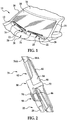
Figure 1 is a partial perspective view of the front of an automotive vehicle having a pair of windshield wiper assemblies, in accordance with the present invention, that are pivotally mounted to wiper arms for reciprocal movement across the windshield of the vehicle; -
Figure 2 is a fragmentary view of the wiper assembly in accordance with the present invention operatively attached to a wiper arm; -
Figure 3 is a fragmentary view of the wiper arm ofFigure 2 ; -
Figure 4 is a perspective view of the wiper assembly of the present invention; -
Figure 5 is a fragmentary view of the wiper assembly of the present invention; -
Figure 6 is a cut-away, cross-sectional view of the wiper assembly of the present invention; and -
Figure 7 is a fragmentary view of the wiping element and wiper guard of the present invention. - Referring now to the Figures, where like numerals are used to designate like structure, a portion of a vehicle is schematically illustrated at 10 in
Figure 1 . The vehicle includes acowl 12, aroof 14, and a pair of laterally spaced front or "A"pillars 16 extending between theroof 14 and thecowl 12. The A-pillars, roof, and cowl cooperate to define a generally rectangular opening which supports a curved or "swept back"glass windshield 18. - A wiper system is generally indicated at 20 in
Figure 1 and is employed to clean theglass windshield 18. Thewiper system 20 includes wiper arms, generally indicated at 22 and wiper assemblies of the present invention, generally indicated at 24, which correspond to the driver and passenger side of thevehicle 10. An electrical motor (not shown but generally known in the art) is employed to power thewiper system 20 and a drive linkage assembly (not shown but generally known in the art) may be employed to direct thewiper assemblies 24, via thewiper arms 22, across thewindshield 18 in an oscillating manner. - Those having ordinary skill in the art will appreciate that while the
wiper arms 22 andwiper assemblies 24 illustrated inFigure 1 are shown in connection with thefront windshield 18 of thevehicle 10,wiper arms 22 and wiper assemblies 24 of the present invention may be employed in other areas of avehicle 10, such as a rear window (not shown) or a head lamp (not shown) that employs awiper system 20. Thus, it will be understood that the present invention is not limited for use solely in connection with a vehicle'swindshield 18, but for use in all applications wherewiper arms 22 andwiper assemblies 24 are employed. - Referring to
Figures 1 and 2 , thewiper arm 22 includes apivot end 26 that is pivotally attached to the drive assembly (not shown) of thewiper system 20 and anelongate body 28. Theelongate body 28 is operatively attached to thepivot end 26 and extends transversely therefrom toward thewiper assembly 24. More specifically, theelongate body 28 is operatively attached to thepivot end 26 in a hinged manner to enable a person to elevate theelongate body 28 away from the surface to be wiped. Articulation between thepivot end 26 andelongate body 28 in this manner is conventionally known to enable maintenance or inspection of thewiper system 20 and/orwindshield 18 as well as for removal and installation ofwiper assemblies 24. Those having ordinary skill in the art will appreciate that thewiper arm 22 may further include a biasing member to impart a downward force through thewiper arm 22 and onto thewiper assembly 24 to facilitate contact between thewiper assembly 24 and thewindshield 18 of thevehicle 10. By way of example, the biasing member may include a spring. It should further be appreciated that theelongate body 28 of thewiper arm 22 may include a cavity adjacent to thepivot end 26 to operatively receive the biasing member. - As shown in
Figures 2 and3 , thewiper arm 22 further includes an attachment member, generally indicated at 30. Theattachment member 30 is operatively attached to theelongate body 28 opposite thepivot end 26 and is adapted to releasably engage awiper assembly 24. More specifically, theattachment member 30 is integrally attached to theelongate body 28. Theattachment member 30 includes abent tab 32 and apin 34 disposed adjacent to thebent tab 32. Thebent tab 32 andpin 34 extend transversely from thebody 28 and parallel with respect to each other. Thepin 34 andbent tab 32 cooperate to attach thewiper arm 22 to awiper assembly 24, as will be described in greater detail below. Additionally, thepin 34 is adapted to operatively engage a portion of thewiper assembly 24 and provide an axis about which thewiper assembly 24 may be rotated, as will also be described in greater detail below. - Referring to
Figures 6 and 7 , thewiper assembly 24 of the present invention includes a wiping element, generally indicated at 36. The wipingelement 36 is adapted to contact the surface of thevehicle 10 to be wiped, namely thewindshield 18, and includes anupper section 38 and alower section 40 that are segmented by alongitudinally extending partition 42. Thepartition 42 provides flexibility between theupper section 38 andlower section 40 during operational movement of thewiper assembly 24. Theupper section 38 is adapted to facilitate attachment to additional components of thewiper assembly 24, as described in greater detail below, while thelower section 40 is adapted to engage the surface to be wiped. The wipingelement 36 includes a predetermined length corresponding to a particular application. It should be appreciated that the wipingelement 36 is constructed from a flexible rubber material but other suitable materials and cross-sectional shapes may be employed without departing from the scope of the invention. By way of example, the wipingelement 36 may be constructed from silicone. The wipingelement 36 is typically manufactured through an extrusion process, which enables the length of the wipingelement 36 to be easily adjusted without a substantial increase to manufacturing expense. However, those having ordinary skill in the art will appreciate that any commercially available manufacturing process such as injection molding may also be employed. - Referring specifically to
Figure 7 , thewindshield wiper assembly 24 of the present invention further includes a wiper guard, generally indicated at 110. Thewiper guard 110 is releasably attached to the wipingelement 36 and is adapted to prevent thewiping element 36 from contacting thewindshield 18. Thewiper guard 110 extends around thelower section 40 and releasably engages the wipingelement 36 adjacent to thepartition 42. More specifically, thewiper guard 110 encloses at least a portion of thelower section 40 to lift the wipingelement 36 off of the surface to be wiped, thereby increasing the longevity of the wipingelement 36. - As illustrated throughout
Figures 1 and6 , thewindshield wiper assembly 24 further includes a superstructure, generally indicated at 44, that operatively engages the wipingelement 36. Thesuperstructure 44 is adapted to distribute downward pressure from thewiper arm 22 across the wiping element. As a result, thesuperstructure 44 includes longitudinal ends 52 and 54 that define a predetermined length capable of facilitating distribution of the downward pressure of thewiper arm 22. In the embodiment illustrated in the figures, thesuperstructure 44 is an elongated beam, generally indicated at 46. Those having ordinary skill in the art will appreciate that the superstructure of the present invention may include multiple elongate beams or a tournament-style superstructure. - As shown in
Figure 6 , theelongated beam 46 includes a super-surface 48 and asubsurface 50 that extend between first and second longitudinal ends 52 and 54, respectively. Theelongated beam 46 is constructed from a resiliently flexible material, such as spring steel or a polymer, and is adapted to distribute force from an intermediate position toward the first and second longitudinal ends 52 and 54. More specifically, theelongated beam 46 receives force from the spring-loadedwiper arm 22 at an intermediate position and distributes this force across the span of theelongated beam 46 toward the first and second longitudinal ends 52 and 54. To that end, theelongated beam 46 is curved longitudinally with a predetermined radius of curvature parallel to the plane of curvature of thewindshield 18 and is sometimes referred to in the related art as a "free form" radius of curvature (hereinafter "windshield curvature"). Accordingly, the curvature of theelongated beam 46 may be symmetrical or asymmetrical depending on the force requirements and the contour of thewindshield 18. The flexible, free form, pre-curved beam straightens out when thewiper arm 22 applies a force thereto to flatten thebeam 46 and directs the wipingelement 36 to contact thewindshield 18. Thus, theelongated beam 46 includes a free-form curvature that ensures force distribution onwindshields 18 having various curvatures that effects proper wrapping about thewindshield 18. - As shown in
Figures 4 and6 , theelongated beam 46 has a substantially constant width and may have a constant thickness throughout the length between the first and second longitudinal ends 52 and 54. The constant width and thickness are adapted to provide high lateral and torsional stiffness to avoid lateral and torsional deflection, which causes the wipingelement 36 to stick/slip ("chatter") on thewindshield 18 during operation. Thus, the cross-section of theelongated beam 46 has a generally rectangular outer profile which makes theelongated beam 46 easier to manufacture. More specifically, where theelongated beam 46 is constructed from metal, such as spring steel, the tools and machinery used to manufacture theelongated beam 46 are less complicated than those required to manufactureelongated beams 46 having varying widths and/or thicknesses. Furthermore, where theelongated beam 46 is constructed from a polymer, such as a thermoplastic elastomer, the tools and extrusion process machinery are also less complicated than those employed to manufactureelongated beams 46 having varying widths and/or thicknesses. However, those having ordinary skill in the art will appreciate that theelongated beam 46 of the present invention may include a varying thickness and/or width without departing from the scope of the invention. By way of example, the width and/or thickness of theelongated beam 46 may taper linearly from the beam center, sinusoidally, parabolically, or asymmetrically. Additionally, although theelongated beam 46 is illustrated throughout the figures as a single, integral piece of material such that it defines a consolidated cross-section, those having ordinary skill in the art will appreciate that theelongated beam 46 may be formed into a single piece by a plurality of laminates. - Referring now to
Figures 4 and5 , thewiper assembly 24 includes additional structure to improve wind lift resistance. More specifically, and as best shown inFigure 4 , thewiper assembly 24 may include first andsecond airfoils airfoils wiper assembly 24. Theairfoils superstructure 44 toward aterminal point airfoils Fig. 3 ). Theairfoils element 36, and are operatively attached to thesuper-surface 48 of theelongated beam 46. Those having ordinary skill in the art will appreciate that theairfoils elongated beam 46 by an adhesive, ultrasonic welding, or by structure, such as tongue and groove or dovetail configuration theairfoils superstructure 44. - With continuing reference to
Figure 4 , thewiper assembly 24 of the present invention further includes a pair of end caps, generally indicated at 60. The end caps 60 are adapted to operatively engage the longitudinal ends 52 and 54. The end caps 60 include a profile that is substantially similar to the contoured profile of the air foils 56A and 56B to provide improved wind lift characteristics and increased aesthetics. A portion of the end caps 60 extends beyond the longitudinal ends 52 and 54 to facilitate contact between the outer extremities of the wipingelement 36 and the surface to be wiped. - The
wiper assembly 24 further includes a coupler, generally indicated at 62, that is disposed along an intermediate position between the first andsecond airfoils wiper arm 22 is distributed, thecoupler 62 of the present invention broadens the initial point through which force is applied from thewiper arm 22 to theelongated beam 46. In this manner, the downward force from thewiper arm 22 is distributed with more efficiency across theelongated beam 46, thereby reducing the likelihood of wind lift and improving wiping action. - Referring to
Figures 2 and4-6 , thecoupler 62 includes opposed first andsecond sidewalls interior surface 64A and 66A. Theinterior surfaces 64A and 66A cooperate to define a track, generally indicated at 68, that operatively receives an intermediate portion of theelongated beam 46. Each of theinterior surfaces 64A and 66A further include at least two transversely extendingtangs subsurface 50 of theelongated beam 46. At least one of thetangs interior surfaces 64A, 66A further include aflange elongated beam 46 relative to thecoupler 62. It should be appreciated that theelongated beam 46 includes notches or apertures (not shown) that are adapted to receive theflanges tangs coupler 62 to accommodate the resiliency of theelongated beam 46. - Additionally, the
coupler 62 includes at least two bridges 74 disposed above thetangs interior surfaces 64A, 66A and prevent vertical movement of theelongated beam 46 relative to thetangs elongated beam 46 is retained within thetrack 68, but remains able to flex in response to the curvature of the surface to be wiped. Those having ordinary skill in the art will appreciate that theelongated beam 46 may be operatively attached to thecoupler 62 by several methods other than as described above. By way of example, thecoupler 62 may be fixed by adhesive, riveted or welded to theelongated beam 46. - The
coupler 62 further includes a top surface, generally indicated at 76, that is disposed between the first andsecond sidewalls top surface 76 cooperates with thefirst sidewall 64 to define a facingedge 78 and further cooperates with thesecond sidewall 66 to define aterminal edge 80. Thetop surface 76 is contoured to define anairfoil 82 between the facingedge 78 and theterminal edge 80 that is adapted to reduce the likelihood of wind lift during operational movement across a surface to be wiped. More specifically, theairfoil 82 defined within thecoupler 62 substantially mimics the profile of theairfoils top surface 76 is contoured to define anairfoil 82 to reduce the likelihood of wind lift, thetop surface 76 may include other undulations to accomplish the intended objective. By way of example, thetop surface 76 may extend from the facingedge 78 toward theterminal edge 80 along a substantially planar incline in a manner that efficiently utilizes airflow to increase the downward force on thewiper assembly 24 to reduce the likelihood of wind lift. - The
top surface 76 further includes aland 84 that is adapted to receive thebent tab 32 of the wiperarm attachment member 30 when thewiper assembly 24 is releasably attached to thewiper arm 22. Theland 84 is a substantially planar section that extends from the facingedge 78 toward theterminal edge 80 along a predetermined angle to further reduce the likelihood of wind lift. The predetermined angle of theland 84 is adapted to correspond to the angle of the bent tab 32 (Fig. 6 ). However, those having ordinary skill in the art will appreciate that theland 84 may include any predetermined angle which may or may not correspond to the angle of thebent tab 32. By way of example, theland 84 may extend from the facingedge 78 to theterminal edge 80 in a manner that is coplanar with the transversely extendingpin 34 of the wiperarm attachment member 30. - Referring back to
Figures 4 and5 , thecoupler 62 further includes a panel, generally indicated at 86. Thepanel 86 is integrated within thefirst sidewall 64 and is adapted to facilitate retention of a portion of the wiperarm attachment member 30. More specifically, thepanel 86 is adapted to prevent lateral movement of thewiper assembly 24 relative to thewiper arm 22. Thepanel 86 includes abore 88 defined therein that is adapted to receive the transversely extendingpin 34 of theattachment member 30 of awiper arm 22. More specifically, thebore 88 provides a surface about which the transversely extendingpin 34 rotates during installation of thewiper assembly 24 to thewiper arm 22, as described in greater detail below. Those having ordinary skill in the art will appreciate that thecoupler 62 may further include asleeve 90 disposed within thebore 88 to provide wear and rotational properties relative to the rotation of thepin 34. - The
coupler 62 further includes adeck 92 that extends transversely from thepanel 86. Thedeck 92 includes arail 94 that extends vertically from thedeck 92, parallel to thepanel 86. Thedeck 92 further includes anaperture 96 defined therein. However those having ordinary skill in the art will appreciate that thedeck 92 may be of solid construction without departing from the scope of the invention. Further by way of example, thedeck 92 and therail 94 may include bifurcated configurations such that there are two decks and two rails cooperating to retain a portion of the wiperarm attachment member 30. - As shown in
Figure 4 , thepanel 86,deck 92 andrail 94 cooperate to define a side-saddle, generally indicated at 98. The side-saddle 98 is adapted to operatively receive a portion of the wiperarm attachment member 30. More specifically, the side-saddle 98 is adapted to restrict the lateral movement of thewiper assembly 24 relative to thewiper arm 22 during operational movement across a surface to be wiped. The side-saddle 98 further includes apillar 100 that extends vertically from thedeck 92, and substantially parallel to thepanel 86. Thepillar 100 is operatively disposed between thepanel 86 and therail 94 and adjacent to thebore 88 and cooperates with thepanel 86 to define aslot 102 that is adapted to receive a portion of the wiperarm attachment member 30. Thepillar 100 provides thewiper assembly 24 with additional retention properties to further prevent lateral movement while maintaining a low vertical profile relative to the surface to be wiped. - During inspection or replacement of a
wiper assembly 24, thewiper arm 22 is often pivoted about thepivot end 26, such that theelongate body 28 is elevated from an initial position substantially parallel to the plane of awindshield 18 to an elevated position that is substantially perpendicular relative to the plane of awindshield 18. The wiper assembly is then rotated about thepin 34 such that a portion of theattachment member 30 disposed within the side-saddle 98 is removed therefrom. Additionally, rotation about thepivot pin 34 disengages thebent tab 32 from theland 84. - During installation/removal of a
wiper assembly 24 onto/from awiper arm 22, thewiper assembly 24 is properly rotated when theland 84 contacts thebent tab 32 in a substantially perpendicular manner. Accordingly, theland 84 provides a positive stop to prevent excess rotation of thewiper assembly 24 relative to thewiper arm 22 and facilitates proper alignment between thebore 88 and the transversely extendingpin 34 of thewiper arm 22. Once thepin 34 is seated within thebore 88, thewiper assembly 24 may be rotated to affect operative engagement between thebent tab 32 and theland 84 as well as a portion of the wiperarm attachment member 30 and the side-saddle 98. - Those having ordinary skill in the art will appreciate that while the present invention is shown in connection with a beam-
style superstructure 44, it is not limited to such construction. By way of example, the superstructure may include what is commonly referred to as a "tournament" style superstructure. A wiper assembly of the present invention having a tournament-style superstructure includes a primary lever, two secondary levers and a series of tertiary levers. The secondary levers are articulated to the primary lever at pivot points located at the opposed, lateral ends of the primary lever. Likewise, the tertiary levers are each articulated to a secondary lever at pivot points located at the opposed lateral ends of the secondary levers. However, those of ordinary skill in the art will appreciate that the superstructure may include a number of different configurations without departing from the scope of the invention. - Where a tournament-style superstructure is employed, the coupler is operatively attached to the primary lever adapted to releasably connect to the wiper arm attachment member in the above-described manner relative to the beam blade-style superstructure. Furthermore, the primary lever may include the airfoil as discussed above relative to a beam blade-style superstructure and the tertiary levers operatively engage the wiper element. Given that the wiper element is virtually in constant contact with the windshield, it will likely wear prior to the other components of the wiper assembly. As a result, the wiper element may be removable where the tournament-style superstructure is employed in order that it may be replaced when worn.
- The present invention provides a
wiper assembly 24 including acoupler 62 having a side-saddle 98 that releasably connects to awiper arm 22. Accordingly, thewiper assembly 24 of the present invention provides a reduced vertical profile for improved wind lift resistance. The present invention further includes awiper assembly 24 having acoupler 62 that includes a contouredtop surface 76 to efficiently utilize air current to maximize downward force applied to awiper assembly 24. Accordingly, thewiper assembly 24 reduces the likelihood of wind lift during operational movement across a surface to be wiped. The present invention also includes acoupler 62 having a side-saddle 98 that prevents lateral movement of thewiper assembly 24 relative to thewiper arm 22. Accordingly, thewiper assembly 24 of the present invention reduces the likelihood of chatter across the surface to be wiped due to inadequate lateral support relative to awiper arm 22. - The invention has been described in an illustrative manner. It is to be understood that the terminology which has been used is intended to be in the nature of words of description rather than of limitation. Many modifications and variations of the invention are possible in light of the above teachings. Therefore, within the scope of the appended claims, the invention may be practiced other than as specifically described.
Claims (11)
- A wiper assembly (24) for use in connection with a wiper arm (22) having an attachment member (30) including a transversely extending pin (34) and a bent tab (32), said wiper assembly (24) comprising:a wiping element (36) adapted to contact the surface to be wiped;a superstructure (44) operatively attached to said wiping element (36) having first and second longitudinal ends (52, 54);at least one airfoil (56) operatively attached to said superstructure (44) that is adapted generate downward force to reduce the likelihood of wind lift; anda coupler (62) operatively attached to said superstructure (44) at an intermediate position between said longitudinal ends (52, 54), said coupler (44) having first and second sidewalls (64, 66), a deck (92) that extends outwardly from said first sidewall (64) and a rail (94) that extends vertically from said deck (92),wherein said deck (92) and said rail (94) cooperate to define a side-saddle (98) that is adapted to facilitate low-profile attachment to a wiper arm attachment member (30) to reduce the likelihood of windlift and reduce lateral movement of a wiper arm attachment member (30) relative to said coupler (62),said coupler (62) further includes a panel (86) defined within said first sidewall (64), said panel (86) having a bore (88) defined therein that is adapted to receive the pin (34) of a wiper arm attachment member (30), characterized in thatsaid coupler (62) further includes a pillar (100) extending vertically from said deck (92) between said panel (86) and said rail (94), said pillar (100) and said panel (86) cooperate to define a slot (102) that is adapted to receive a portion of a wiper arm attachment member (30) to reduce the likelihood of lateral movement of the wiper arm attachment member (30) relative to said coupler (62).
- The wiper assembly (24) as set forth in claim 1 wherein said first and second sidewalls (64, 66) of said coupler (62) each further include opposed interior surfaces (64A, 66A) that cooperate to define a track (68) that operatively engages an intermediate portion of said superstructure (44) to facilitate distribution of downward force from a wiper arm (22) toward said longitudinal ends (52, 54) to reduce the likelihood of wind lift.
- The wiper assembly (24) as set forth in claim 1 further includes a wiper guard (110) releasably attached to said wiping element (36) that is adapted to prevent said wiping element (36) from contacting a surface to be wiped.
- The wiper assembly (24) as set forth in claim 1 wherein said at least one airfoil (56) includes first and second airfoils (56A, 56B) disposed between said coupler (62) and said longitudinal ends (52, 54), said first and second airfoils (56A, 56B) having a contoured profile that tapers inwardly from said superstructure toward a terminal point (58A, 58B) to define an asymmetrical cross-section.
- The wiper assembly (24) as set forth in claim 1 further includes a pair of end caps (60) that are adapted to operatively engage said longitudinal ends (52, 54) of said superstructure (44), said end caps (60) include an asymmetrical cross-sectional profile that corresponds to the profile of said at least one airfoils (56) and extend beyond said longitudinal ends (52, 54) to facilitate contact between the outer extremities of said wiping element (36) and the surface to be wiped to reduce the likelihood of wind lift.
- The wiper assembly (24) as set forth in claim 1, wherein said superstructure (44) is defined by an elongated beam (46) that is adapted to distribute force from a wiper arm (22) toward said first and second longitudinal ends (52, 54);such that the at least one airfoil (56) is operatively attached to said elongated beam (46); andsuch that the coupler (62) is operatively attached to said elongated beam (46) at an intermediate position between said longitudinal ends (52, 54).
- The wiper assembly (24) as set forth in claim 6 further includes a wiper guard (110) releasably attached to said wiping element (36) that is adapted to prevent said wiping element (36) from contacting the surface to be wiped.
- The wiper assembly (24) as set forth in claim 6 wherein said at least one airfoil (56) includes first and second airfoils (56A, 56B) disposed between said coupler (62) and said longitudinal ends (52, 54), said first and second airfoils (56A, 56B) having a contoured profile that tapers inwardly from said superstructure (44) toward a terminal point (58A, 58B) to define an asymmetrical cross-section.
- The wiper assembly (24) as set forth in claim 6 wherein said first and second sidewalls (64, 66) of said coupler (62) each further include opposed interior surfaces (64A, 66A) that cooperate to define a track (68) that operatively receives an intermediate portion of said elongated beam (46), each of said interior surfaces (64A, 66A) having at least two transversely extending tangs (70, 72) operatively disposed adjacent to the terminal ends of said coupler (62).
- The wiper assembly (24) as set forth in claim 9 wherein said coupler (62) further includes at least two bridges (74) disposed above said tangs (70, 72) that operatively connect said interior surfaces (64A, 66A), said bridges (74) and said tangs (70, 72) cooperate to retain said elongated beam (46) within said track (68) while maintaining the resiliency of said elongated beam (46) within said track (68).
- The wiper assembly (24) as set forth in claim 6 wherein said coupler (62) further includes a top surface (76) disposed between said first and second sidewalls (64, 66), said top surface (76) includes a contoured profile that defines an airfoil (82) to reduce the likelihood of wind lift during operational movement across a surface to be wiped.
Applications Claiming Priority (2)
| Application Number | Priority Date | Filing Date | Title |
|---|---|---|---|
| US92198607P | 2007-04-05 | 2007-04-05 | |
| PCT/US2008/004480 WO2008124113A1 (en) | 2007-04-05 | 2008-04-07 | Wiper assembly having side-saddle coupler |
Publications (3)
| Publication Number | Publication Date |
|---|---|
| EP2134576A1 EP2134576A1 (en) | 2009-12-23 |
| EP2134576A4 EP2134576A4 (en) | 2015-07-15 |
| EP2134576B1 true EP2134576B1 (en) | 2018-12-26 |
Family
ID=39831270
Family Applications (1)
| Application Number | Title | Priority Date | Filing Date |
|---|---|---|---|
| EP08727313.2A Not-in-force EP2134576B1 (en) | 2007-04-05 | 2008-04-07 | Wiper assembly having side-saddle coupler |
Country Status (6)
| Country | Link |
|---|---|
| US (1) | US8042218B2 (en) |
| EP (1) | EP2134576B1 (en) |
| CN (1) | CN101657341B (en) |
| BR (1) | BRPI0809993A2 (en) |
| GB (1) | GB2461215B (en) |
| WO (1) | WO2008124113A1 (en) |
Families Citing this family (27)
| Publication number | Priority date | Publication date | Assignee | Title |
|---|---|---|---|---|
| CA2541641C (en) | 2005-04-04 | 2014-02-11 | Trico Products Corporation | Wiper coupler and wiper assembly incorporating same |
| DE102010001900A1 (en) * | 2010-02-12 | 2011-08-18 | Robert Bosch GmbH, 70469 | Wiper blade, in particular for windows of motor vehicles, and method for producing a wiper blade |
| US9457769B2 (en) * | 2011-02-23 | 2016-10-04 | Mitsuba Corporation | Wiper blade |
| US9174609B2 (en) | 2011-04-21 | 2015-11-03 | Pylon Manufacturing Corp. | Wiper blade with cover |
| US9457768B2 (en) | 2011-04-21 | 2016-10-04 | Pylon Manufacturing Corp. | Vortex damping wiper blade |
| US9174611B2 (en) | 2011-07-28 | 2015-11-03 | Pylon Manufacturing Corp. | Windshield wiper adapter, connector and assembly |
| US8806700B2 (en) | 2011-07-29 | 2014-08-19 | Pylon Manufacturing Corporation | Wiper blade connector |
| US9108595B2 (en) | 2011-07-29 | 2015-08-18 | Pylon Manufacturing Corporation | Windshield wiper connector |
| CA2865292C (en) | 2012-02-24 | 2018-03-13 | Pylon Manufacturing Corp. | Wiper blade |
| US20130219649A1 (en) | 2012-02-24 | 2013-08-29 | Pylon Manufacturing Corp. | Wiper blade |
| US10829092B2 (en) | 2012-09-24 | 2020-11-10 | Pylon Manufacturing Corp. | Wiper blade with modular mounting base |
| US9260084B2 (en) | 2013-01-03 | 2016-02-16 | Trico Products Corporation | Wiper coupler adapter and wiper assembly incorporating same |
| US10166951B2 (en) | 2013-03-15 | 2019-01-01 | Pylon Manufacturing Corp. | Windshield wiper connector |
| CN105283358A (en) * | 2013-04-12 | 2016-01-27 | 费德罗-莫格尔公司 | Windscreen wiper device |
| US9227599B2 (en) | 2013-05-02 | 2016-01-05 | Trico Products Corporation | Mounting assembly for wiper blade and wiper arm |
| US9771052B2 (en) * | 2013-07-02 | 2017-09-26 | Trico Products Corporation | Universal coupler assembly and wiper assembly incorporating the same |
| US9493140B2 (en) | 2013-12-02 | 2016-11-15 | Trico Products Corporation | Coupler assembly for wiper assembly |
| US9505380B2 (en) | 2014-03-07 | 2016-11-29 | Pylon Manufacturing Corp. | Windshield wiper connector and assembly |
| US9663071B2 (en) | 2014-05-29 | 2017-05-30 | Trico Products Corporation | Wiper adapter and wiper assembly incorporating same |
| USD777079S1 (en) | 2014-10-03 | 2017-01-24 | Pylon Manufacturing Corp. | Wiper blade frame |
| FR3037899B1 (en) * | 2015-06-29 | 2019-04-12 | Valeo Systemes D'essuyage | ORGAN FOR A CONNECTION SYSTEM FROM A WIPER TO A WIPER ARM |
| WO2017075066A1 (en) | 2015-10-26 | 2017-05-04 | Pylon Manufacturing Corp. | Wiper blade |
| US11040705B2 (en) | 2016-05-19 | 2021-06-22 | Pylon Manufacturing Corp. | Windshield wiper connector |
| US10623565B2 (en) | 2018-02-09 | 2020-04-14 | Afiniti Europe Technologies Limited | Techniques for behavioral pairing in a contact center system |
| US11250359B2 (en) | 2018-05-30 | 2022-02-15 | Afiniti, Ltd. | Techniques for workforce management in a task assignment system |
| US10496438B1 (en) | 2018-09-28 | 2019-12-03 | Afiniti, Ltd. | Techniques for adapting behavioral pairing to runtime conditions in a task assignment system |
| US11144344B2 (en) | 2019-01-17 | 2021-10-12 | Afiniti, Ltd. | Techniques for behavioral pairing in a task assignment system |
Family Cites Families (50)
| Publication number | Priority date | Publication date | Assignee | Title |
|---|---|---|---|---|
| DE1028896B (en) | 1954-06-24 | 1958-04-24 | Avog Elektro Und Feinmechanik | Wiper rail for windshield wiper |
| US2974341A (en) | 1956-09-24 | 1961-03-14 | Gen Motors Corp | Connector for windshield wiper blade |
| US3179969A (en) | 1963-10-04 | 1965-04-27 | Tridon Mfg Ltd | Automobile windshield wiper backing members |
| US3192551A (en) | 1964-08-31 | 1965-07-06 | Walter D Appel | Windshield wiper blade assembly |
| DE1505397A1 (en) | 1965-05-07 | 1969-10-30 | Bosch Gmbh Robert | Windshield wipers for vehicles |
| US3317945A (en) | 1965-09-17 | 1967-05-09 | Hastings Mfg Co | Molded windshield wiper blade |
| US3378874A (en) | 1966-06-10 | 1968-04-23 | Trico Products Corp | Windshield wiper assembly |
| US3641614A (en) | 1970-03-16 | 1972-02-15 | Alfred Anthony Newsome | Windshield wiper assemblies |
| US3845519A (en) | 1972-06-29 | 1974-11-05 | W Quinlan | Windshield wiper assembly |
| US4132490A (en) | 1975-06-07 | 1979-01-02 | Paul Journee, S.A. | Device for securing a wiper blade to an arm |
| FR2324489A1 (en) | 1975-09-16 | 1977-04-15 | Journee Paul Sa | DEVICE FOR ATTACHING A WIPER BLADE TO AN ARM |
| US4300259A (en) * | 1978-06-23 | 1981-11-17 | Arman S.P.A. | Device for connecting a wiper blade holder to a wiper arm |
| US4224001A (en) | 1979-05-24 | 1980-09-23 | The Anderson Company Of Indiana | Windshield wiper connecting pin adaptor |
| US4416032A (en) | 1981-10-05 | 1983-11-22 | Mohnach Michael G | Connector adaptor for pin-type blade |
| GB8726140D0 (en) * | 1987-11-07 | 1987-12-09 | Wright C W | Wiper blades |
| US4980944A (en) | 1989-07-13 | 1991-01-01 | Pylon Manufacturing Corporation | Universal wiper blade pin connector |
| US5084933A (en) | 1990-10-19 | 1992-02-04 | Franz Buechele | Adaptor for windshield wiper arms |
| FR2705936B1 (en) | 1993-06-04 | 1995-08-04 | Valeo Systemes Dessuyage | Wiper device comprising an articulation between a crank and a connecting rod. |
| US5606765A (en) * | 1994-09-14 | 1997-03-04 | Rally Accessories, Inc. | Windshield wiper connector for accommodating different hook-type wiper arms |
| DE19729865A1 (en) | 1997-07-11 | 1999-01-14 | Bosch Gmbh Robert | Windshield wipers for motor vehicles |
| DE19757872A1 (en) | 1997-12-24 | 1999-07-01 | Bosch Gmbh Robert | Wiper device for windows of motor vehicles with an oscillating wiper arm guided on the motor vehicle |
| DE19833666B4 (en) | 1998-07-27 | 2015-06-25 | Robert Bosch Gmbh | Wiper blade for windows of motor vehicles |
| DE19838883A1 (en) | 1998-08-27 | 2000-03-02 | Bosch Gmbh Robert | Device for connecting a wiper blade to a wiper arm |
| HU226808B1 (en) | 1999-05-28 | 2009-11-30 | Bosch Gmbh Robert | Wiper blade for the glass surfaces of a motor vehicle |
| DE19924662B4 (en) * | 1999-05-28 | 2007-06-28 | Robert Bosch Gmbh | Wiper device for windows of motor vehicles |
| DE19951363A1 (en) | 1999-10-26 | 2001-05-03 | Bosch Gmbh Robert | Wiper blade for windows of motor vehicles |
| DE29918961U1 (en) | 1999-10-28 | 2001-03-08 | Bosch Gmbh Robert | Wiper device for windows of motor vehicles |
| DE19952054A1 (en) | 1999-10-28 | 2001-05-03 | Bosch Gmbh Robert | Wiper device for windows of motor vehicles |
| DE10000381A1 (en) | 2000-01-07 | 2001-11-22 | Valeo Auto Electric Gmbh | Wiper blade for cleaning windows on vehicles, especially motor vehicles |
| US6550096B1 (en) | 2000-07-06 | 2003-04-22 | Trico Products Corporation | Beam blade wiper assembly having improved coupler |
| DE10034475A1 (en) | 2000-07-15 | 2002-01-31 | Bosch Gmbh Robert | Windscreen wiper has protective profile with inward-facing lips at top which fit into longitudinal grooves in wiper strip, strip being held at end by lugs on profile, one of which reaches across whole width of profile while other leaves gap |
| DE10036135A1 (en) * | 2000-07-25 | 2002-02-28 | Volkswagen Ag | Vehicle windscreen wiper has blade holding block with bearing for pivot bolt and securing hook |
| DE50107150D1 (en) | 2000-10-28 | 2005-09-22 | Bosch Gmbh Robert | JOINT-FREE WIPER BLADE, ESPECIALLY FOR A MOTOR VEHICLE |
| DE10162399A1 (en) | 2001-12-19 | 2003-07-10 | Bosch Gmbh Robert | Wipers with a wiper arm |
| DE10162401A1 (en) | 2001-12-19 | 2003-07-10 | Bosch Gmbh Robert | Wipers with a wiper arm |
| DE10207706A1 (en) | 2002-02-22 | 2003-09-04 | Bosch Gmbh Robert | Wiper blade for cleaning windows, especially of motor vehicles |
| EP1519862B1 (en) | 2002-06-28 | 2007-02-21 | Robert Bosch Gmbh | Wiper blade |
| DE10259477B4 (en) * | 2002-12-19 | 2020-12-10 | Robert Bosch Gmbh | Prevention arrangement of a wiper device for windows of motor vehicles |
| DE10259856B4 (en) | 2002-12-20 | 2016-06-30 | Robert Bosch Gmbh | Wiper arm of a wiper device for windows of motor vehicles |
| US7207082B2 (en) * | 2002-12-27 | 2007-04-24 | Albert Lee | Windshield wiper frame connector which accommodates different size wiper arms |
| DE102004016017A1 (en) * | 2004-04-01 | 2005-10-20 | Bosch Gmbh Robert | wiper blade |
| DE102004029795A1 (en) * | 2004-06-19 | 2006-01-05 | Bayerische Motoren Werke Ag | Windshield wiper for vehicle has mounting component rotatable about drag axis and held within connection component |
| CN2723287Y (en) * | 2004-08-09 | 2005-09-07 | 杨志铭 | Composite wind shield wiper switching device |
| US20060130263A1 (en) * | 2004-12-17 | 2006-06-22 | Coughlin Timothy J | Wiper coupler and wiper assembly incorporating same |
| DE102005037269A1 (en) * | 2005-02-03 | 2006-08-10 | Robert Bosch Gmbh | Wiper blade of a windshield wiper with a protective rail |
| DE102005037709A1 (en) * | 2005-08-10 | 2006-10-26 | Daimlerchrysler Ag | Windscreen wiper unit, comprising adapter secured to blade with hook-shaped extension |
| TWM288872U (en) * | 2005-09-25 | 2006-03-21 | Shih-Hsien Huang | Connection device for car wiper arm |
| US7802341B2 (en) * | 2006-10-24 | 2010-09-28 | Trico Products Corporation | Wiper system having a pin-style wiper arm and wiper assembly |
| US20080235896A1 (en) * | 2007-03-28 | 2008-10-02 | Ming-Hui Cheng | Wiper blade structure |
| US7921504B1 (en) * | 2009-12-29 | 2011-04-12 | Fu Gang Co., Ltd. | Frame coupling structure of windshield wiper |
-
2008
- 2008-04-04 US US12/062,976 patent/US8042218B2/en active Active
- 2008-04-07 GB GB0919063.8A patent/GB2461215B/en not_active Expired - Fee Related
- 2008-04-07 BR BRPI0809993-6A2A patent/BRPI0809993A2/en not_active IP Right Cessation
- 2008-04-07 WO PCT/US2008/004480 patent/WO2008124113A1/en active Search and Examination
- 2008-04-07 CN CN2008800113248A patent/CN101657341B/en not_active Expired - Fee Related
- 2008-04-07 EP EP08727313.2A patent/EP2134576B1/en not_active Not-in-force
Non-Patent Citations (1)
| Title |
|---|
| None * |
Also Published As
| Publication number | Publication date |
|---|---|
| BRPI0809993A2 (en) | 2014-10-14 |
| GB2461215B (en) | 2013-02-20 |
| GB2461215A (en) | 2009-12-30 |
| CN101657341B (en) | 2012-02-15 |
| CN101657341A (en) | 2010-02-24 |
| US20080256740A1 (en) | 2008-10-23 |
| GB0919063D0 (en) | 2009-12-16 |
| US8042218B2 (en) | 2011-10-25 |
| EP2134576A1 (en) | 2009-12-23 |
| WO2008124113A1 (en) | 2008-10-16 |
| WO2008124113A9 (en) | 2009-02-26 |
| EP2134576A4 (en) | 2015-07-15 |
Similar Documents
| Publication | Publication Date | Title |
|---|---|---|
| EP2134576B1 (en) | Wiper assembly having side-saddle coupler | |
| US7802341B2 (en) | Wiper system having a pin-style wiper arm and wiper assembly | |
| CA2896733C (en) | Wiper coupler adaptor and wiper assembly incorporating same | |
| US8555456B2 (en) | Beam blade windshield wiper assembly | |
| US20150151718A1 (en) | Wiper coupler assembly and wiper assembly incorporating same | |
| US7861363B2 (en) | Beam blade windshield wiper assembly having an airfoil | |
| KR101599098B1 (en) | Windshield wiper assembly having an optimized airfoil | |
| US8857009B2 (en) | Beam blade wiper assembly having self-locking end cap | |
| US20150013093A1 (en) | Wiper coupler adaptor and wiper assembly incorporating same | |
| US20140101884A1 (en) | Beam blade wiper assembly and method of assembly | |
| EP3126197B1 (en) | Winter wiper assembly | |
| US10391980B2 (en) | End cap for wiper assembly | |
| US9744945B2 (en) | End cap for retaining wiping element of wiper assembly | |
| CA2891382A1 (en) | Airfoil for wiper assembly |
Legal Events
| Date | Code | Title | Description |
|---|---|---|---|
| PUAI | Public reference made under article 153(3) epc to a published international application that has entered the european phase |
Free format text: ORIGINAL CODE: 0009012 |
|
| 17P | Request for examination filed |
Effective date: 20091005 |
|
| AK | Designated contracting states |
Kind code of ref document: A1 Designated state(s): AT BE BG CH CY CZ DE DK EE ES FI FR GB GR HR HU IE IS IT LI LT LU LV MC MT NL NO PL PT RO SE SI SK TR |
|
| DAX | Request for extension of the european patent (deleted) | ||
| RA4 | Supplementary search report drawn up and despatched (corrected) |
Effective date: 20150612 |
|
| RIC1 | Information provided on ipc code assigned before grant |
Ipc: B60S 1/38 20060101ALI20150608BHEP Ipc: B60S 1/40 20060101AFI20150608BHEP |
|
| GRAP | Despatch of communication of intention to grant a patent |
Free format text: ORIGINAL CODE: EPIDOSNIGR1 |
|
| STAA | Information on the status of an ep patent application or granted ep patent |
Free format text: STATUS: GRANT OF PATENT IS INTENDED |
|
| INTG | Intention to grant announced |
Effective date: 20180629 |
|
| GRAS | Grant fee paid |
Free format text: ORIGINAL CODE: EPIDOSNIGR3 |
|
| GRAA | (expected) grant |
Free format text: ORIGINAL CODE: 0009210 |
|
| STAA | Information on the status of an ep patent application or granted ep patent |
Free format text: STATUS: THE PATENT HAS BEEN GRANTED |
|
| AK | Designated contracting states |
Kind code of ref document: B1 Designated state(s): AT BE BG CH CY CZ DE DK EE ES FI FR GB GR HR HU IE IS IT LI LT LU LV MC MT NL NO PL PT RO SE SI SK TR |
|
| REG | Reference to a national code |
Ref country code: GB Ref legal event code: FG4D |
|
| REG | Reference to a national code |
Ref country code: CH Ref legal event code: EP |
|
| REG | Reference to a national code |
Ref country code: DE Ref legal event code: R096 Ref document number: 602008058461 Country of ref document: DE |
|
| REG | Reference to a national code |
Ref country code: AT Ref legal event code: REF Ref document number: 1080984 Country of ref document: AT Kind code of ref document: T Effective date: 20190115 |
|
| REG | Reference to a national code |
Ref country code: IE Ref legal event code: FG4D |
|
| PG25 | Lapsed in a contracting state [announced via postgrant information from national office to epo] |
Ref country code: FI Free format text: LAPSE BECAUSE OF FAILURE TO SUBMIT A TRANSLATION OF THE DESCRIPTION OR TO PAY THE FEE WITHIN THE PRESCRIBED TIME-LIMIT Effective date: 20181226 Ref country code: NO Free format text: LAPSE BECAUSE OF FAILURE TO SUBMIT A TRANSLATION OF THE DESCRIPTION OR TO PAY THE FEE WITHIN THE PRESCRIBED TIME-LIMIT Effective date: 20190326 Ref country code: LV Free format text: LAPSE BECAUSE OF FAILURE TO SUBMIT A TRANSLATION OF THE DESCRIPTION OR TO PAY THE FEE WITHIN THE PRESCRIBED TIME-LIMIT Effective date: 20181226 Ref country code: HR Free format text: LAPSE BECAUSE OF FAILURE TO SUBMIT A TRANSLATION OF THE DESCRIPTION OR TO PAY THE FEE WITHIN THE PRESCRIBED TIME-LIMIT Effective date: 20181226 Ref country code: BG Free format text: LAPSE BECAUSE OF FAILURE TO SUBMIT A TRANSLATION OF THE DESCRIPTION OR TO PAY THE FEE WITHIN THE PRESCRIBED TIME-LIMIT Effective date: 20190326 Ref country code: LT Free format text: LAPSE BECAUSE OF FAILURE TO SUBMIT A TRANSLATION OF THE DESCRIPTION OR TO PAY THE FEE WITHIN THE PRESCRIBED TIME-LIMIT Effective date: 20181226 |
|
| REG | Reference to a national code |
Ref country code: NL Ref legal event code: MP Effective date: 20181226 |
|
| REG | Reference to a national code |
Ref country code: LT Ref legal event code: MG4D |
|
| PG25 | Lapsed in a contracting state [announced via postgrant information from national office to epo] |
Ref country code: SE Free format text: LAPSE BECAUSE OF FAILURE TO SUBMIT A TRANSLATION OF THE DESCRIPTION OR TO PAY THE FEE WITHIN THE PRESCRIBED TIME-LIMIT Effective date: 20181226 Ref country code: GR Free format text: LAPSE BECAUSE OF FAILURE TO SUBMIT A TRANSLATION OF THE DESCRIPTION OR TO PAY THE FEE WITHIN THE PRESCRIBED TIME-LIMIT Effective date: 20190327 |
|
| REG | Reference to a national code |
Ref country code: AT Ref legal event code: MK05 Ref document number: 1080984 Country of ref document: AT Kind code of ref document: T Effective date: 20181226 |
|
| PG25 | Lapsed in a contracting state [announced via postgrant information from national office to epo] |
Ref country code: NL Free format text: LAPSE BECAUSE OF FAILURE TO SUBMIT A TRANSLATION OF THE DESCRIPTION OR TO PAY THE FEE WITHIN THE PRESCRIBED TIME-LIMIT Effective date: 20181226 |
|
| PG25 | Lapsed in a contracting state [announced via postgrant information from national office to epo] |
Ref country code: IT Free format text: LAPSE BECAUSE OF FAILURE TO SUBMIT A TRANSLATION OF THE DESCRIPTION OR TO PAY THE FEE WITHIN THE PRESCRIBED TIME-LIMIT Effective date: 20181226 Ref country code: PT Free format text: LAPSE BECAUSE OF FAILURE TO SUBMIT A TRANSLATION OF THE DESCRIPTION OR TO PAY THE FEE WITHIN THE PRESCRIBED TIME-LIMIT Effective date: 20190426 Ref country code: CZ Free format text: LAPSE BECAUSE OF FAILURE TO SUBMIT A TRANSLATION OF THE DESCRIPTION OR TO PAY THE FEE WITHIN THE PRESCRIBED TIME-LIMIT Effective date: 20181226 Ref country code: PL Free format text: LAPSE BECAUSE OF FAILURE TO SUBMIT A TRANSLATION OF THE DESCRIPTION OR TO PAY THE FEE WITHIN THE PRESCRIBED TIME-LIMIT Effective date: 20181226 Ref country code: ES Free format text: LAPSE BECAUSE OF FAILURE TO SUBMIT A TRANSLATION OF THE DESCRIPTION OR TO PAY THE FEE WITHIN THE PRESCRIBED TIME-LIMIT Effective date: 20181226 |
|
| PGFP | Annual fee paid to national office [announced via postgrant information from national office to epo] |
Ref country code: DE Payment date: 20190620 Year of fee payment: 12 |
|
| PG25 | Lapsed in a contracting state [announced via postgrant information from national office to epo] |
Ref country code: EE Free format text: LAPSE BECAUSE OF FAILURE TO SUBMIT A TRANSLATION OF THE DESCRIPTION OR TO PAY THE FEE WITHIN THE PRESCRIBED TIME-LIMIT Effective date: 20181226 Ref country code: RO Free format text: LAPSE BECAUSE OF FAILURE TO SUBMIT A TRANSLATION OF THE DESCRIPTION OR TO PAY THE FEE WITHIN THE PRESCRIBED TIME-LIMIT Effective date: 20181226 Ref country code: IS Free format text: LAPSE BECAUSE OF FAILURE TO SUBMIT A TRANSLATION OF THE DESCRIPTION OR TO PAY THE FEE WITHIN THE PRESCRIBED TIME-LIMIT Effective date: 20190426 Ref country code: SK Free format text: LAPSE BECAUSE OF FAILURE TO SUBMIT A TRANSLATION OF THE DESCRIPTION OR TO PAY THE FEE WITHIN THE PRESCRIBED TIME-LIMIT Effective date: 20181226 |
|
| REG | Reference to a national code |
Ref country code: DE Ref legal event code: R097 Ref document number: 602008058461 Country of ref document: DE |
|
| PG25 | Lapsed in a contracting state [announced via postgrant information from national office to epo] |
Ref country code: DK Free format text: LAPSE BECAUSE OF FAILURE TO SUBMIT A TRANSLATION OF THE DESCRIPTION OR TO PAY THE FEE WITHIN THE PRESCRIBED TIME-LIMIT Effective date: 20181226 Ref country code: AT Free format text: LAPSE BECAUSE OF FAILURE TO SUBMIT A TRANSLATION OF THE DESCRIPTION OR TO PAY THE FEE WITHIN THE PRESCRIBED TIME-LIMIT Effective date: 20181226 |
|
| PGFP | Annual fee paid to national office [announced via postgrant information from national office to epo] |
Ref country code: GB Payment date: 20190424 Year of fee payment: 12 |
|
| PLBE | No opposition filed within time limit |
Free format text: ORIGINAL CODE: 0009261 |
|
| STAA | Information on the status of an ep patent application or granted ep patent |
Free format text: STATUS: NO OPPOSITION FILED WITHIN TIME LIMIT |
|
| REG | Reference to a national code |
Ref country code: CH Ref legal event code: PL |
|
| 26N | No opposition filed |
Effective date: 20190927 |
|
| REG | Reference to a national code |
Ref country code: BE Ref legal event code: MM Effective date: 20190430 |
|
| PG25 | Lapsed in a contracting state [announced via postgrant information from national office to epo] |
Ref country code: MC Free format text: LAPSE BECAUSE OF FAILURE TO SUBMIT A TRANSLATION OF THE DESCRIPTION OR TO PAY THE FEE WITHIN THE PRESCRIBED TIME-LIMIT Effective date: 20181226 Ref country code: LU Free format text: LAPSE BECAUSE OF NON-PAYMENT OF DUE FEES Effective date: 20190407 |
|
| PG25 | Lapsed in a contracting state [announced via postgrant information from national office to epo] |
Ref country code: CH Free format text: LAPSE BECAUSE OF NON-PAYMENT OF DUE FEES Effective date: 20190430 Ref country code: LI Free format text: LAPSE BECAUSE OF NON-PAYMENT OF DUE FEES Effective date: 20190430 |
|
| PG25 | Lapsed in a contracting state [announced via postgrant information from national office to epo] |
Ref country code: SI Free format text: LAPSE BECAUSE OF FAILURE TO SUBMIT A TRANSLATION OF THE DESCRIPTION OR TO PAY THE FEE WITHIN THE PRESCRIBED TIME-LIMIT Effective date: 20181226 Ref country code: BE Free format text: LAPSE BECAUSE OF NON-PAYMENT OF DUE FEES Effective date: 20190430 Ref country code: FR Free format text: LAPSE BECAUSE OF NON-PAYMENT OF DUE FEES Effective date: 20190430 |
|
| PG25 | Lapsed in a contracting state [announced via postgrant information from national office to epo] |
Ref country code: TR Free format text: LAPSE BECAUSE OF FAILURE TO SUBMIT A TRANSLATION OF THE DESCRIPTION OR TO PAY THE FEE WITHIN THE PRESCRIBED TIME-LIMIT Effective date: 20181226 |
|
| PG25 | Lapsed in a contracting state [announced via postgrant information from national office to epo] |
Ref country code: IE Free format text: LAPSE BECAUSE OF NON-PAYMENT OF DUE FEES Effective date: 20190407 |
|
| REG | Reference to a national code |
Ref country code: DE Ref legal event code: R119 Ref document number: 602008058461 Country of ref document: DE |
|
| PG25 | Lapsed in a contracting state [announced via postgrant information from national office to epo] |
Ref country code: DE Free format text: LAPSE BECAUSE OF NON-PAYMENT OF DUE FEES Effective date: 20201103 |
|
| GBPC | Gb: european patent ceased through non-payment of renewal fee |
Effective date: 20200407 |
|
| PG25 | Lapsed in a contracting state [announced via postgrant information from national office to epo] |
Ref country code: GB Free format text: LAPSE BECAUSE OF NON-PAYMENT OF DUE FEES Effective date: 20200407 |
|
| PG25 | Lapsed in a contracting state [announced via postgrant information from national office to epo] |
Ref country code: CY Free format text: LAPSE BECAUSE OF FAILURE TO SUBMIT A TRANSLATION OF THE DESCRIPTION OR TO PAY THE FEE WITHIN THE PRESCRIBED TIME-LIMIT Effective date: 20181226 |
|
| PG25 | Lapsed in a contracting state [announced via postgrant information from national office to epo] |
Ref country code: HU Free format text: LAPSE BECAUSE OF FAILURE TO SUBMIT A TRANSLATION OF THE DESCRIPTION OR TO PAY THE FEE WITHIN THE PRESCRIBED TIME-LIMIT; INVALID AB INITIO Effective date: 20080407 Ref country code: MT Free format text: LAPSE BECAUSE OF FAILURE TO SUBMIT A TRANSLATION OF THE DESCRIPTION OR TO PAY THE FEE WITHIN THE PRESCRIBED TIME-LIMIT Effective date: 20181226 |