EP2134015B1 - Time reference identification - Google Patents
Time reference identification Download PDFInfo
- Publication number
- EP2134015B1 EP2134015B1 EP08740152.7A EP08740152A EP2134015B1 EP 2134015 B1 EP2134015 B1 EP 2134015B1 EP 08740152 A EP08740152 A EP 08740152A EP 2134015 B1 EP2134015 B1 EP 2134015B1
- Authority
- EP
- European Patent Office
- Prior art keywords
- transmitter
- signal received
- time reference
- replica
- communications network
- Prior art date
- Legal status (The legal status is an assumption and is not a legal conclusion. Google has not performed a legal analysis and makes no representation as to the accuracy of the status listed.)
- Not-in-force
Links
Images

Classifications
-
- H—ELECTRICITY
- H04—ELECTRIC COMMUNICATION TECHNIQUE
- H04L—TRANSMISSION OF DIGITAL INFORMATION, e.g. TELEGRAPHIC COMMUNICATION
- H04L27/00—Modulated-carrier systems
- H04L27/26—Systems using multi-frequency codes
- H04L27/2601—Multicarrier modulation systems
- H04L27/2647—Arrangements specific to the receiver only
- H04L27/2655—Synchronisation arrangements
- H04L27/2668—Details of algorithms
- H04L27/2673—Details of algorithms characterised by synchronisation parameters
- H04L27/2675—Pilot or known symbols
-
- H—ELECTRICITY
- H04—ELECTRIC COMMUNICATION TECHNIQUE
- H04L—TRANSMISSION OF DIGITAL INFORMATION, e.g. TELEGRAPHIC COMMUNICATION
- H04L27/00—Modulated-carrier systems
- H04L27/26—Systems using multi-frequency codes
- H04L27/2601—Multicarrier modulation systems
- H04L27/2647—Arrangements specific to the receiver only
- H04L27/2655—Synchronisation arrangements
- H04L27/2668—Details of algorithms
- H04L27/2681—Details of algorithms characterised by constraints
- H04L27/2685—Speed of convergence
-
- H—ELECTRICITY
- H04—ELECTRIC COMMUNICATION TECHNIQUE
- H04W—WIRELESS COMMUNICATION NETWORKS
- H04W56/00—Synchronisation arrangements
- H04W56/0055—Synchronisation arrangements determining timing error of reception due to propagation delay
- H04W56/0065—Synchronisation arrangements determining timing error of reception due to propagation delay using measurement of signal travel time
- H04W56/007—Open loop measurement
- H04W56/0075—Open loop measurement based on arrival time vs. expected arrival time
- H04W56/0085—Open loop measurement based on arrival time vs. expected arrival time detecting a given structure in the signal
-
- H—ELECTRICITY
- H04—ELECTRIC COMMUNICATION TECHNIQUE
- H04L—TRANSMISSION OF DIGITAL INFORMATION, e.g. TELEGRAPHIC COMMUNICATION
- H04L5/00—Arrangements affording multiple use of the transmission path
- H04L5/0001—Arrangements for dividing the transmission path
- H04L5/0003—Two-dimensional division
- H04L5/0005—Time-frequency
- H04L5/0007—Time-frequency the frequencies being orthogonal, e.g. OFDM(A), DMT
-
- H—ELECTRICITY
- H04—ELECTRIC COMMUNICATION TECHNIQUE
- H04L—TRANSMISSION OF DIGITAL INFORMATION, e.g. TELEGRAPHIC COMMUNICATION
- H04L5/00—Arrangements affording multiple use of the transmission path
- H04L5/003—Arrangements for allocating sub-channels of the transmission path
- H04L5/0053—Allocation of signaling, i.e. of overhead other than pilot signals
Description
- The present invention relates to a method of performing cell timing acquisition for a mobile terminal in a cellular telecommunications network. The preferred embodiments of the invention will be described in the context of an OFDM wireless telecommunications network, however the present invention should not be considered as being limited to that exemplary implementation.
- The initial cell timing synchronization is a critical and necessary step in decoding OFDM downlink transmissions in a OFDM mobile terminal, such as in the proposed long term evolution (LTE) standard of the 3GPP. Systems operating under this proposed standard are often termed Super3G networks.
- The conventional method of acquiring the cell timing is to use a cell synchronization channel of the network. In this process, the mobile terminal knows the structure of the synchronization channel, and derives all other system parameters (for example, scrambling code and the number of used carriers) by decoding the synchronization channel. Since the synchronization channel is transmitted infrequently, the detection takes relatively long time.
- Document
US 2003/091022 A1 (BLANZ JOSEF [DE] ET AL) 15 May 2003 (2003-05-15), discloses the use of a pilot detector based on the GROUP ID scrambling code derived from the PSC/SSC synchronizing portion. - It therefore would be advantageous to have a method that in certain cases would decrease the time taken to acquire cell timing by the mobile terminal.
- It should be noted that the discussion of prior art herein is not an admission by the applicant that that prior art forms part of the common general knowledge in the art at the priority date of the present application.
- Any occurrence of the term "embodiment" in the description has to be considered as an "aspect of the invention", the invention being defined in the appended independent claims.
- In a first aspect the present invention provides a method of identifying a time reference in signal received from a transmitter of a communications network, including: generating a replica of a synchronization sequence on the basis of at least one known transmission parameter; comparing the replica of a synchronization sequence to a sequence derived from the signal received from the transmitter to identify a reference point in the signal received from the transmitter.
- The transmitter can be further configured to transmit a one or more signals on a plurality of subcarriers, and the known transmission parameters include one or more of the following transmission parameters: pilot channel symbol position; a scrambling code of the signal; and a subcarrier map of the signal.
- The at least one known transmission parameter can be derived from a previous communication with the transmitter.
- The method can include, generating a partial synchronization sequence replica for each subcarrier to be received; and combining the partial synchronization sequence replicas into a single synchronization sequence replica. The synchronization sequence can correspond to a predefined transmission interval.
- The predefined transmission interval is preferably a transmission slot.
- The step of comparing the replica of a synchronization sequence to a sequence derived from the signal received can include, combining the replica of a synchronization sequence with the sequence derived from the signal received on a sample by sample basis to determine a peak correlation value between the signals. In the event that the peak correlation value exceeds a predetermined threshold, the method can include identifying the time position of the peak as the time reference in the signal received.
- In a second aspect the present invention provides a method of synchronizing a receiver with a transmitter of a communications network, including: identifying a time reference in signal received from the transmitter using a method according to an embodiment of the first aspect of the present invention; and synchronizing the receiver timing with reference to the identified time reference.
- In a further aspect the present invention provides a method, in a mobile terminal communicating with communications network, including: attempting to perform synchronization with a transmitter of the communications network as described above; and in the event that synchronization fails, attempting synchronization with the transmitter using an alternative method.
- The method is preferably performed upon start-up of the mobile terminal and/or when transmission parameters of the transmitter change.
- In a fourth aspect the present invention provides a method, in a mobile terminal communicating with communications network, including: storing at least one known transmission parameters relating to the communications network, for use in synchronizing the mobile terminal with the communications network.
- The method can further include synchronizing the mobile terminal using a method according to an embodiment of the present invention.
- The transmission parameters can include one or more of the following transmission parameters: pilot channel symbol position; a scrambling code of a signal; and a subcarrier map of a signal.
- In a further aspect the present invention provides a mobile terminal including a receiver, and a processing device, said processing device being configured to cause the mobile terminal to implement a method as according to an embodiment of any one of the aforementioned aspects of the present invention.
- A preferred form of the present invention will now be described, by way of non-limiting example only, with reference to the accompanying drawings.
-
-
Figure 1 illustrates a method of generating a replica synchronization signal in an embodiment of the present invention; and -
Figure 2 illustrates a method of timing detection used in an embodiment of the present invention. - For convenience terminology adopted by the 3GPP (3rd Generation Partnership Project) will be used throughout detailed description of this specification e.g. User Equipment and UE. However the present invention should not be considered as being limited to application in systems implemented in accordance with 3GPP standards.
- The inventors have determined that in the cases when cell bandwidth mode and cell scrambling code is known a priori, it is possible to use the cell's pilot channel to perform a fast slot timing detection. Typically the bandwidth mode and scrambling code will be known a priori when the mobile terminal is already initialized for a given network provider, and the last used cell has been stored in the mobile terminal. In such case, cell timing can be made more efficient by first trying to synchronize onto this "last known" cell first, as it is likely to result in quick synchronization. If this initial attempt fails, the mobile terminal can proceed with a standard cell search process.
- Cell synchronization operates by performing a cross-correlation between a received signal and a replica of that signal generated by the mobile terminal. In the preferred embodiments the structure of the replica is derived from known pilot channel symbol position, scrambling code and subcarrier map.
Figure 1 shows an example of how a replica can be generated in an embodiment of the present invention. It will be noted that the replica generation process is computationally intensive. However it only needs to be performed after start-up of the mobile terminal or whenever one of the input parameters, for example the scrambling code changes. - It is proposed that the 3GPP LTE slot will consist of 7 OFDM symbols. Some of these symbols contain so called 'pilot symbols', which consist of known carriers or 'symbols' with specified phase and amplitude at pre-defined positions in time and frequency. The
replica generation device 100 onFigure 1 converts this known time-frequency matrix of pilot symbols into time-domain waveform, then to its frequency-domain equivalent, called the sync_pilot_replica as follows. In aninitial step 102 to determine which pilot symbols will be received, the number of sub-carriers being received by the mobile terminal is used to generate a pilot symbol sequence. Next, at 104 the pilot sequence is scrambled using a known scrambling sequence. Instep 106 the used subcarriers are mapped according to the known subcarrier mapping look-up table. The resulting signal is converted to a time domain signal, e.g. by applying an inverse fast Fourier transform (FFT) at 108. In an exemplary embodiment, using sampling rate of 7.68MHz, each OFDM symbol will be produced and transmitted with inverse FFT ofsize 512. In this case operations on individual OFDM symbols are processed withFFT size 512. - The slot is then assembled and pilot symbols are then inserted at
step 110. Next the sub-frame is converted into the frequency domain, e.g. by FFT atstep 112. In keeping with the example above, it should be noted that as 3GPP LTE slot is 0.5 milliseconds long, meaning that it consists of 3840 samples. As the conversion to the frequency domain is performed over whole slot an FFT size of 4096 is used, since FFT size needs to be an integer power of two. - The symbols are then conjugated in
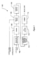
step 114 to generate the sync_pilot_replica output. - Now the sync_pilot_replica is known, timing detection can be performed in accordance with the
flowchart 200 ofFigure 2 . - An incoming data block, which in the example given above will includes 3840 samples, is first processed, at
step 202, by extending the block to 4096 samples by padding the block with zeros, so that it is the same size as the FFT to be used. The resulting 4096sample data block is then converted to a frequency domain signal by FFT at 204. - The frequency-domain pilot replica, sync_pilot_replica, is multiplied with the 4096 point FFT of incoming signal at 206. The result is then (in step 208) converted to time domain using an inverse FFT, of
size 4096. This overall operation is mathematically equivalent to cross-correlation of the two input signals in the time domain. Next, at 210, the power of the correlation signal is determined instep 210 by calculating the sum of the squares of the I and Q components of the output of theinverse FFT step 208. So the result at the output of the I2+Q2 block is a correlation power profile. - The output of the I2+Q2 block 210 is a set of 4096 samples, which contains a sharp peak. The position of the peak within this block of samples corresponds to the position of the slot boundaries (which can be used to determine the slot timing) in the input, relative to the incoming block of 3840 samples.
- The system then performs an analysis of the correlation profile and determines the actual slot timing. This analysis begins by accumulating power for each sample position over N slots in
step 212. The accumulated power is then used to identify where in the slot the peak falls, instep 214. Next, in 216 the power of the identified peak is compared to a threshold level to determine if it is sufficiently strong. If the power of the peak exceeds the threshold level then a frame edge is deemed to have been identified. In this case the slot timing is determined by subtracting the cyclic prefix length from the determined peak position. - Certain embodiments of the present invention will have very good performance compared to convention methods of determining cell timing. Since the correlation is performed for the entire slot at once, using FFT, the result can be obtained quickly, if an efficient FFT implementation is available.
- It will be understood that the invention disclosed and defined in this specification extends to all alternative combinations of two or more of the individual features mentioned or evident from the text or drawings. All of these different combinations constitute various alternative aspects of the invention.
- It will also be understood that the term "comprises" (or its grammatical variants) as used in this specification is equivalent to the term "includes" and should not be taken as excluding the presence of other elements or features.
- This application is based upon and claims the benefit of priority from Australian provisional patent application No.
2007901835, filed on April 5, 2007
Claims (8)
- A method of identifying a time reference in a signal received from a transmitter of a communications network, including:generating a replica which is provided for cell synchronization and which is derived from a selected one or more of known transmission parameters; andcomparing the replica for cell synchronization to a sequence derived from the signal received from the transmitter to identify the time reference in the signal received from the transmitter, characterised in thatthe received signal includes one or more signals on a plurality of subcarriers and wherein the one or more of the following known transmission parameters include:pilot channel symbol position;a scrambling code of the signal; anda subcarrier map of the signal;wherein the known transmission parameters are derived from a previous communication with the transmitter.
- The method of identifying a time reference in a signal received from a transmitter of a communications network according to claim 1, wherein the method includes:generating a partial replica for cell synchronization for each subcarrier to be received; andcombining the partial replicas for cell synchronization into a single replica for cell synchronization.
- The method of identifying a time reference in a signal received from a transmitter of a communications network according to any one of claims 1 or 2, wherein the step of comparing the replica for cell synchronization to a sequence derived from the signal received includes combining the replica for cell synchronization with the sequence derived from the signal received on a sample by sample basis to determine a peak correlation value between the signals.
- The method of identifying a time reference in a signal received from a transmitter of a communications network according to claim 3, wherein in the event that the peak correlation value exceeds a predetermined threshold, the method includes identifying the time position of the peak as the time reference in the signal received.
- A method of synchronizing a receiver with a transmitter of a communications network, including:identifying a time reference in a signal received from the transmitter using the method according to any one of claims 1 through 4;synchronizing the receiver timing with reference to the identified time reference.
- A method, in a mobile terminal communicating with a communications network, including:attempting to perform synchronization with a transmitter of the communications network in accordance with claim 5; andin the event that synchronization fails, attempting synchronization with the transmitter using an alternative method.
- The method according to claim 6, wherein the method is performed upon start-up of the mobile terminal and/or when transmission parameters of the transmitter change.
- A mobile terminal including a receiver, and a processing device, said processing device being configured to cause the mobile terminal to implement the method as claimed in any one of claims 1 to 7.
Applications Claiming Priority (2)
| Application Number | Priority Date | Filing Date | Title |
|---|---|---|---|
| AU2007901835A AU2007901835A0 (en) | 2007-04-05 | Timing acquisition | |
| PCT/JP2008/057051 WO2008126882A1 (en) | 2007-04-05 | 2008-04-03 | Time reference identification method |
Publications (3)
| Publication Number | Publication Date |
|---|---|
| EP2134015A1 EP2134015A1 (en) | 2009-12-16 |
| EP2134015A4 EP2134015A4 (en) | 2012-10-31 |
| EP2134015B1 true EP2134015B1 (en) | 2014-09-10 |
Family
ID=39863978
Family Applications (1)
| Application Number | Title | Priority Date | Filing Date |
|---|---|---|---|
| EP08740152.7A Not-in-force EP2134015B1 (en) | 2007-04-05 | 2008-04-03 | Time reference identification |
Country Status (5)
| Country | Link |
|---|---|
| US (1) | US8284883B2 (en) |
| EP (1) | EP2134015B1 (en) |
| JP (1) | JP4936027B2 (en) |
| CN (1) | CN101658009A (en) |
| WO (1) | WO2008126882A1 (en) |
Citations (1)
| Publication number | Priority date | Publication date | Assignee | Title |
|---|---|---|---|---|
| US20030091022A1 (en) * | 2001-11-09 | 2003-05-15 | Josef Blanz | Communications in an asynchronous wireless network |
Family Cites Families (19)
| Publication number | Priority date | Publication date | Assignee | Title |
|---|---|---|---|---|
| FR2710214B1 (en) * | 1993-09-15 | 1995-10-20 | Alcatel Mobile Comm France | Threshold detector for a digital radio transmission system, devices comprising such a threshold detector and corresponding use. |
| FI100159B (en) * | 1995-01-19 | 1997-09-30 | Nokia Telecommunications Oy | Synchronization of a telecommunication connection in a mobile communication system |
| FI101116B (en) * | 1995-08-14 | 1998-04-15 | Nokia Telecommunications Oy | Synchronization of communication connection in the system of a mobile communication |
| US5974080A (en) * | 1998-06-09 | 1999-10-26 | Texas Instruments Incorporated | Hierarchical-serial acquisition method for CDMA systems using pilot PN codes |
| US6567482B1 (en) * | 1999-03-05 | 2003-05-20 | Telefonaktiebolaget Lm Ericsson (Publ) | Method and apparatus for efficient synchronization in spread spectrum communications |
| US6115406A (en) * | 1999-09-10 | 2000-09-05 | Interdigital Technology Corporation | Transmission using an antenna array in a CDMA communication system |
| US6424678B1 (en) * | 2000-08-01 | 2002-07-23 | Motorola, Inc. | Scalable pattern methodology for multi-carrier communication systems |
| US20020173286A1 (en) * | 2001-04-06 | 2002-11-21 | Bengt Lindoff | Radiocommunication employing selected synchronization technique |
| US7499698B2 (en) * | 2002-01-28 | 2009-03-03 | Qualcomm Incorporated | Synchronization of stored service parameters in a communication system |
| US20040062300A1 (en) * | 2002-10-01 | 2004-04-01 | Mcdonough John G. | System and method for detecting direct sequence spread spectrum signals using batch processing of independent parameters |
| TWI222798B (en) * | 2003-04-02 | 2004-10-21 | Mediatek Inc | Multiple base station automatic frequency control architecture in wireless communication system |
| GB2407003B (en) | 2003-10-10 | 2006-08-09 | Toshiba Res Europ Ltd | Wireless access systems |
| US8027372B2 (en) * | 2004-06-18 | 2011-09-27 | Qualcomm Incorporated | Signal acquisition in a wireless communication system |
| WO2006092852A1 (en) * | 2005-03-02 | 2006-09-08 | Fujitsu Limited | Ofdm communication system and ofdm communication method |
| JP4546342B2 (en) * | 2005-07-07 | 2010-09-15 | パナソニック株式会社 | Transmitting apparatus and transmitting method |
| WO2007023810A1 (en) * | 2005-08-23 | 2007-03-01 | Matsushita Electric Industrial Co., Ltd. | Scalable bandwidth system, radio base station apparatus, synchronous channel transmitting method and transmission method |
| US7760793B2 (en) * | 2005-10-28 | 2010-07-20 | Ülo Parts | Pilot scrambling enabling direct pilot sequence detection in initial acquisition in evolved UTRA |
| EP2063542B1 (en) * | 2006-06-16 | 2013-06-12 | Sharp Kabushiki Kaisha | Data creation device, data creation method, base station, mobile station, synchronization detection method, sector identification method, information detection method, and mobile communication system |
| KR101280437B1 (en) * | 2007-01-04 | 2013-06-28 | 엘지전자 주식회사 | Mobile Communication Terminal and Method for Data Synchronization |
-
2008
- 2008-04-03 US US12/594,706 patent/US8284883B2/en not_active Expired - Fee Related
- 2008-04-03 EP EP08740152.7A patent/EP2134015B1/en not_active Not-in-force
- 2008-04-03 WO PCT/JP2008/057051 patent/WO2008126882A1/en active Application Filing
- 2008-04-03 JP JP2009509364A patent/JP4936027B2/en not_active Expired - Fee Related
- 2008-04-03 CN CN200880011477A patent/CN101658009A/en active Pending
Patent Citations (1)
| Publication number | Priority date | Publication date | Assignee | Title |
|---|---|---|---|---|
| US20030091022A1 (en) * | 2001-11-09 | 2003-05-15 | Josef Blanz | Communications in an asynchronous wireless network |
Also Published As
| Publication number | Publication date |
|---|---|
| WO2008126882A1 (en) | 2008-10-23 |
| JP4936027B2 (en) | 2012-05-23 |
| US8284883B2 (en) | 2012-10-09 |
| JPWO2008126882A1 (en) | 2010-07-22 |
| EP2134015A4 (en) | 2012-10-31 |
| CN101658009A (en) | 2010-02-24 |
| EP2134015A1 (en) | 2009-12-16 |
| US20100046653A1 (en) | 2010-02-25 |
Similar Documents
| Publication | Publication Date | Title |
|---|---|---|
| EP2282469B1 (en) | Technique for determining a frequency offset | |
| US9479218B2 (en) | Methods for LTE cell search with large frequency offset | |
| RU2335091C2 (en) | Method and device for detection of cell in system of multiple access with orthogonal frequency division | |
| EP2518961B1 (en) | Method and device for detecting primary synchronization signal and generating sequence in long term evolution (lte) system | |
| EP3008849B1 (en) | Filterbank-based multicarrier transmitter for transmitting a multicarrier signal | |
| US7778153B2 (en) | Method for estimating transmission delay and receiver using the same | |
| EP1850548A1 (en) | Method and apparatus for the detection of common control channel in an OFDMA cellular communication system | |
| EP1952549A1 (en) | Method and system for synchronization in a communication system | |
| US20080316947A1 (en) | METHOD AND APPARATUS FOR 3G LTE FDD and TDD DETECTION USING REFERENCE SIGNAL CORRELATION | |
| KR20090113893A (en) | Subcarrier spacing identification | |
| WO2007083912A1 (en) | Method and apparatus for transmitting synchronization signals in an ofdm based cellular communications system | |
| US8923338B2 (en) | Method and device for receiving non-synchronous signal in OFDMA system | |
| CN102461102A (en) | Process for estimating the channel from the pss signal in a lte communication network, and receiver for the same | |
| US10148413B2 (en) | Method for synchronising an FBMC system using a RACH channel | |
| EP2097994A1 (en) | Method for generating downlink signal, and method for searching cell | |
| CN103905363A (en) | Secondary synchronization signal (SSS) detection method and device and network mode judgment method | |
| Nasraoui et al. | Robust doubly-differential primary synchronization approach for 3GPP LTE systems | |
| CN117320046A (en) | CRS searching method, LTE time alignment error measuring method and user equipment | |
| US20100220710A1 (en) | Multicarrier transmitting apparatus | |
| EP2134015B1 (en) | Time reference identification | |
| KR102005616B1 (en) | Digital audio broadcasting system based on ofdm and method of mode and frame detection using the same | |
| Lee et al. | Use of training subcarriers for synchronization in low latency uplink communication with GFDM | |
| KR101000791B1 (en) | System, apparatus and method for frame synchronization of digital radio mondiale receiver | |
| Krishna et al. | Carrier frequency offset estimations in OFDM-downlink LTE systems | |
| KR101342801B1 (en) | Apparatus and method for estimating channel using code expansion in mobile telecommunication system |
Legal Events
| Date | Code | Title | Description |
|---|---|---|---|
| PUAI | Public reference made under article 153(3) epc to a published international application that has entered the european phase |
Free format text: ORIGINAL CODE: 0009012 |
|
| 17P | Request for examination filed |
Effective date: 20090922 |
|
| AK | Designated contracting states |
Kind code of ref document: A1 Designated state(s): AT BE BG CH CY CZ DE DK EE ES FI FR GB GR HR HU IE IS IT LI LT LU LV MC MT NL NO PL PT RO SE SI SK TR |
|
| DAX | Request for extension of the european patent (deleted) | ||
| A4 | Supplementary search report drawn up and despatched |
Effective date: 20120927 |
|
| RIC1 | Information provided on ipc code assigned before grant |
Ipc: H04L 27/26 20060101ALI20120921BHEP Ipc: H04J 11/00 20060101AFI20120921BHEP Ipc: H04B 1/707 20110101ALI20120921BHEP |
|
| 17Q | First examination report despatched |
Effective date: 20130307 |
|
| REG | Reference to a national code |
Ref country code: DE Ref legal event code: R079 Ref document number: 602008034339 Country of ref document: DE Free format text: PREVIOUS MAIN CLASS: H04J0011000000 Ipc: H04L0027260000 |
|
| GRAP | Despatch of communication of intention to grant a patent |
Free format text: ORIGINAL CODE: EPIDOSNIGR1 |
|
| RIC1 | Information provided on ipc code assigned before grant |
Ipc: H04L 27/26 20060101AFI20140325BHEP Ipc: H04W 56/00 20090101ALI20140325BHEP |
|
| INTG | Intention to grant announced |
Effective date: 20140409 |
|
| GRAS | Grant fee paid |
Free format text: ORIGINAL CODE: EPIDOSNIGR3 |
|
| GRAA | (expected) grant |
Free format text: ORIGINAL CODE: 0009210 |
|
| AK | Designated contracting states |
Kind code of ref document: B1 Designated state(s): AT BE BG CH CY CZ DE DK EE ES FI FR GB GR HR HU IE IS IT LI LT LU LV MC MT NL NO PL PT RO SE SI SK TR |
|
| REG | Reference to a national code |
Ref country code: GB Ref legal event code: FG4D |
|
| REG | Reference to a national code |
Ref country code: CH Ref legal event code: EP |
|
| REG | Reference to a national code |
Ref country code: IE Ref legal event code: FG4D |
|
| REG | Reference to a national code |
Ref country code: AT Ref legal event code: REF Ref document number: 687179 Country of ref document: AT Kind code of ref document: T Effective date: 20141015 |
|
| REG | Reference to a national code |
Ref country code: DE Ref legal event code: R096 Ref document number: 602008034339 Country of ref document: DE Effective date: 20141016 |
|
| PG25 | Lapsed in a contracting state [announced via postgrant information from national office to epo] |
Ref country code: NO Free format text: LAPSE BECAUSE OF FAILURE TO SUBMIT A TRANSLATION OF THE DESCRIPTION OR TO PAY THE FEE WITHIN THE PRESCRIBED TIME-LIMIT Effective date: 20141210 Ref country code: SE Free format text: LAPSE BECAUSE OF FAILURE TO SUBMIT A TRANSLATION OF THE DESCRIPTION OR TO PAY THE FEE WITHIN THE PRESCRIBED TIME-LIMIT Effective date: 20140910 Ref country code: GR Free format text: LAPSE BECAUSE OF FAILURE TO SUBMIT A TRANSLATION OF THE DESCRIPTION OR TO PAY THE FEE WITHIN THE PRESCRIBED TIME-LIMIT Effective date: 20141211 Ref country code: ES Free format text: LAPSE BECAUSE OF FAILURE TO SUBMIT A TRANSLATION OF THE DESCRIPTION OR TO PAY THE FEE WITHIN THE PRESCRIBED TIME-LIMIT Effective date: 20140910 Ref country code: LT Free format text: LAPSE BECAUSE OF FAILURE TO SUBMIT A TRANSLATION OF THE DESCRIPTION OR TO PAY THE FEE WITHIN THE PRESCRIBED TIME-LIMIT Effective date: 20140910 Ref country code: FI Free format text: LAPSE BECAUSE OF FAILURE TO SUBMIT A TRANSLATION OF THE DESCRIPTION OR TO PAY THE FEE WITHIN THE PRESCRIBED TIME-LIMIT Effective date: 20140910 |
|
| REG | Reference to a national code |
Ref country code: NL Ref legal event code: VDEP Effective date: 20140910 |
|
| REG | Reference to a national code |
Ref country code: LT Ref legal event code: MG4D |
|
| PG25 | Lapsed in a contracting state [announced via postgrant information from national office to epo] |
Ref country code: LV Free format text: LAPSE BECAUSE OF FAILURE TO SUBMIT A TRANSLATION OF THE DESCRIPTION OR TO PAY THE FEE WITHIN THE PRESCRIBED TIME-LIMIT Effective date: 20140910 Ref country code: HR Free format text: LAPSE BECAUSE OF FAILURE TO SUBMIT A TRANSLATION OF THE DESCRIPTION OR TO PAY THE FEE WITHIN THE PRESCRIBED TIME-LIMIT Effective date: 20140910 Ref country code: CY Free format text: LAPSE BECAUSE OF FAILURE TO SUBMIT A TRANSLATION OF THE DESCRIPTION OR TO PAY THE FEE WITHIN THE PRESCRIBED TIME-LIMIT Effective date: 20140910 |
|
| REG | Reference to a national code |
Ref country code: AT Ref legal event code: MK05 Ref document number: 687179 Country of ref document: AT Kind code of ref document: T Effective date: 20140910 |
|
| PG25 | Lapsed in a contracting state [announced via postgrant information from national office to epo] |
Ref country code: NL Free format text: LAPSE BECAUSE OF FAILURE TO SUBMIT A TRANSLATION OF THE DESCRIPTION OR TO PAY THE FEE WITHIN THE PRESCRIBED TIME-LIMIT Effective date: 20140910 |
|
| PG25 | Lapsed in a contracting state [announced via postgrant information from national office to epo] |
Ref country code: IS Free format text: LAPSE BECAUSE OF FAILURE TO SUBMIT A TRANSLATION OF THE DESCRIPTION OR TO PAY THE FEE WITHIN THE PRESCRIBED TIME-LIMIT Effective date: 20150110 Ref country code: EE Free format text: LAPSE BECAUSE OF FAILURE TO SUBMIT A TRANSLATION OF THE DESCRIPTION OR TO PAY THE FEE WITHIN THE PRESCRIBED TIME-LIMIT Effective date: 20140910 Ref country code: SK Free format text: LAPSE BECAUSE OF FAILURE TO SUBMIT A TRANSLATION OF THE DESCRIPTION OR TO PAY THE FEE WITHIN THE PRESCRIBED TIME-LIMIT Effective date: 20140910 Ref country code: CZ Free format text: LAPSE BECAUSE OF FAILURE TO SUBMIT A TRANSLATION OF THE DESCRIPTION OR TO PAY THE FEE WITHIN THE PRESCRIBED TIME-LIMIT Effective date: 20140910 Ref country code: RO Free format text: LAPSE BECAUSE OF FAILURE TO SUBMIT A TRANSLATION OF THE DESCRIPTION OR TO PAY THE FEE WITHIN THE PRESCRIBED TIME-LIMIT Effective date: 20140910 Ref country code: PT Free format text: LAPSE BECAUSE OF FAILURE TO SUBMIT A TRANSLATION OF THE DESCRIPTION OR TO PAY THE FEE WITHIN THE PRESCRIBED TIME-LIMIT Effective date: 20150112 |
|
| PG25 | Lapsed in a contracting state [announced via postgrant information from national office to epo] |
Ref country code: AT Free format text: LAPSE BECAUSE OF FAILURE TO SUBMIT A TRANSLATION OF THE DESCRIPTION OR TO PAY THE FEE WITHIN THE PRESCRIBED TIME-LIMIT Effective date: 20140910 Ref country code: PL Free format text: LAPSE BECAUSE OF FAILURE TO SUBMIT A TRANSLATION OF THE DESCRIPTION OR TO PAY THE FEE WITHIN THE PRESCRIBED TIME-LIMIT Effective date: 20140910 |
|
| PGFP | Annual fee paid to national office [announced via postgrant information from national office to epo] |
Ref country code: GB Payment date: 20150202 Year of fee payment: 8 |
|
| REG | Reference to a national code |
Ref country code: DE Ref legal event code: R097 Ref document number: 602008034339 Country of ref document: DE |
|
| PLBE | No opposition filed within time limit |
Free format text: ORIGINAL CODE: 0009261 |
|
| STAA | Information on the status of an ep patent application or granted ep patent |
Free format text: STATUS: NO OPPOSITION FILED WITHIN TIME LIMIT |
|
| PG25 | Lapsed in a contracting state [announced via postgrant information from national office to epo] |
Ref country code: DK Free format text: LAPSE BECAUSE OF FAILURE TO SUBMIT A TRANSLATION OF THE DESCRIPTION OR TO PAY THE FEE WITHIN THE PRESCRIBED TIME-LIMIT Effective date: 20140910 |
|
| 26N | No opposition filed |
Effective date: 20150611 |
|
| REG | Reference to a national code |
Ref country code: DE Ref legal event code: R119 Ref document number: 602008034339 Country of ref document: DE |
|
| PG25 | Lapsed in a contracting state [announced via postgrant information from national office to epo] |
Ref country code: SI Free format text: LAPSE BECAUSE OF FAILURE TO SUBMIT A TRANSLATION OF THE DESCRIPTION OR TO PAY THE FEE WITHIN THE PRESCRIBED TIME-LIMIT Effective date: 20140910 Ref country code: LU Free format text: LAPSE BECAUSE OF FAILURE TO SUBMIT A TRANSLATION OF THE DESCRIPTION OR TO PAY THE FEE WITHIN THE PRESCRIBED TIME-LIMIT Effective date: 20150403 Ref country code: MC Free format text: LAPSE BECAUSE OF FAILURE TO SUBMIT A TRANSLATION OF THE DESCRIPTION OR TO PAY THE FEE WITHIN THE PRESCRIBED TIME-LIMIT Effective date: 20140910 |
|
| REG | Reference to a national code |
Ref country code: CH Ref legal event code: PL |
|
| REG | Reference to a national code |
Ref country code: IE Ref legal event code: MM4A |
|
| PG25 | Lapsed in a contracting state [announced via postgrant information from national office to epo] |
Ref country code: LI Free format text: LAPSE BECAUSE OF NON-PAYMENT OF DUE FEES Effective date: 20150430 Ref country code: CH Free format text: LAPSE BECAUSE OF NON-PAYMENT OF DUE FEES Effective date: 20150430 Ref country code: DE Free format text: LAPSE BECAUSE OF NON-PAYMENT OF DUE FEES Effective date: 20151103 Ref country code: IT Free format text: LAPSE BECAUSE OF NON-PAYMENT OF DUE FEES Effective date: 20150403 |
|
| REG | Reference to a national code |
Ref country code: FR Ref legal event code: ST Effective date: 20151231 |
|
| PG25 | Lapsed in a contracting state [announced via postgrant information from national office to epo] |
Ref country code: FR Free format text: LAPSE BECAUSE OF NON-PAYMENT OF DUE FEES Effective date: 20150430 |
|
| PG25 | Lapsed in a contracting state [announced via postgrant information from national office to epo] |
Ref country code: IE Free format text: LAPSE BECAUSE OF NON-PAYMENT OF DUE FEES Effective date: 20150403 |
|
| PG25 | Lapsed in a contracting state [announced via postgrant information from national office to epo] |
Ref country code: BE Free format text: LAPSE BECAUSE OF FAILURE TO SUBMIT A TRANSLATION OF THE DESCRIPTION OR TO PAY THE FEE WITHIN THE PRESCRIBED TIME-LIMIT Effective date: 20140910 |
|
| GBPC | Gb: european patent ceased through non-payment of renewal fee |
Effective date: 20160403 |
|
| PG25 | Lapsed in a contracting state [announced via postgrant information from national office to epo] |
Ref country code: MT Free format text: LAPSE BECAUSE OF FAILURE TO SUBMIT A TRANSLATION OF THE DESCRIPTION OR TO PAY THE FEE WITHIN THE PRESCRIBED TIME-LIMIT Effective date: 20140910 |
|
| PG25 | Lapsed in a contracting state [announced via postgrant information from national office to epo] |
Ref country code: GB Free format text: LAPSE BECAUSE OF NON-PAYMENT OF DUE FEES Effective date: 20160403 |
|
| PG25 | Lapsed in a contracting state [announced via postgrant information from national office to epo] |
Ref country code: HU Free format text: LAPSE BECAUSE OF FAILURE TO SUBMIT A TRANSLATION OF THE DESCRIPTION OR TO PAY THE FEE WITHIN THE PRESCRIBED TIME-LIMIT; INVALID AB INITIO Effective date: 20080403 Ref country code: BG Free format text: LAPSE BECAUSE OF FAILURE TO SUBMIT A TRANSLATION OF THE DESCRIPTION OR TO PAY THE FEE WITHIN THE PRESCRIBED TIME-LIMIT Effective date: 20140910 |
|
| PG25 | Lapsed in a contracting state [announced via postgrant information from national office to epo] |
Ref country code: TR Free format text: LAPSE BECAUSE OF FAILURE TO SUBMIT A TRANSLATION OF THE DESCRIPTION OR TO PAY THE FEE WITHIN THE PRESCRIBED TIME-LIMIT Effective date: 20140910 |