EP2133711A1 - Method for distance measuring and data transfer in a key down radar system - Google Patents
Method for distance measuring and data transfer in a key down radar system Download PDFInfo
- Publication number
- EP2133711A1 EP2133711A1 EP08010824A EP08010824A EP2133711A1 EP 2133711 A1 EP2133711 A1 EP 2133711A1 EP 08010824 A EP08010824 A EP 08010824A EP 08010824 A EP08010824 A EP 08010824A EP 2133711 A1 EP2133711 A1 EP 2133711A1
- Authority
- EP
- European Patent Office
- Prior art keywords
- continuous wave
- signal
- wave signal
- frequency
- receiving module
- Prior art date
- Legal status (The legal status is an assumption and is not a legal conclusion. Google has not performed a legal analysis and makes no representation as to the accuracy of the status listed.)
- Granted
Links
- 238000000034 method Methods 0.000 title claims abstract description 21
- 230000004044 response Effects 0.000 claims abstract description 19
- 230000010363 phase shift Effects 0.000 claims abstract description 5
- 238000005259 measurement Methods 0.000 claims description 29
- 230000005540 biological transmission Effects 0.000 claims description 22
- 238000012806 monitoring device Methods 0.000 claims description 16
- 238000011156 evaluation Methods 0.000 claims description 13
- 238000012544 monitoring process Methods 0.000 claims description 3
- 238000005070 sampling Methods 0.000 claims 4
- 238000006073 displacement reaction Methods 0.000 claims 2
- 238000010408 sweeping Methods 0.000 claims 2
- 238000009434 installation Methods 0.000 claims 1
- 230000004807 localization Effects 0.000 description 10
- 238000010586 diagram Methods 0.000 description 4
- 230000008569 process Effects 0.000 description 4
- 230000003071 parasitic effect Effects 0.000 description 3
- 238000012545 processing Methods 0.000 description 3
- 238000001228 spectrum Methods 0.000 description 3
- 230000001629 suppression Effects 0.000 description 3
- 230000008901 benefit Effects 0.000 description 2
- 238000006243 chemical reaction Methods 0.000 description 2
- 230000007613 environmental effect Effects 0.000 description 2
- 239000002184 metal Substances 0.000 description 2
- 230000000737 periodic effect Effects 0.000 description 2
- 238000000926 separation method Methods 0.000 description 2
- 238000010183 spectrum analysis Methods 0.000 description 2
- 230000008859 change Effects 0.000 description 1
- 238000004891 communication Methods 0.000 description 1
- 238000013479 data entry Methods 0.000 description 1
- 230000006866 deterioration Effects 0.000 description 1
- 230000000694 effects Effects 0.000 description 1
- 238000005562 fading Methods 0.000 description 1
- 238000001914 filtration Methods 0.000 description 1
- 230000002452 interceptive effect Effects 0.000 description 1
- 230000007774 longterm Effects 0.000 description 1
- 238000004519 manufacturing process Methods 0.000 description 1
- 238000010327 methods by industry Methods 0.000 description 1
- 239000000203 mixture Substances 0.000 description 1
- 230000006855 networking Effects 0.000 description 1
- 230000005855 radiation Effects 0.000 description 1
- 230000009467 reduction Effects 0.000 description 1
- 230000002123 temporal effect Effects 0.000 description 1
Images


Classifications
-
- G—PHYSICS
- G01—MEASURING; TESTING
- G01S—RADIO DIRECTION-FINDING; RADIO NAVIGATION; DETERMINING DISTANCE OR VELOCITY BY USE OF RADIO WAVES; LOCATING OR PRESENCE-DETECTING BY USE OF THE REFLECTION OR RERADIATION OF RADIO WAVES; ANALOGOUS ARRANGEMENTS USING OTHER WAVES
- G01S13/00—Systems using the reflection or reradiation of radio waves, e.g. radar systems; Analogous systems using reflection or reradiation of waves whose nature or wavelength is irrelevant or unspecified
- G01S13/87—Combinations of radar systems, e.g. primary radar and secondary radar
- G01S13/876—Combination of several spaced transponders or reflectors of known location for determining the position of a receiver
-
- G—PHYSICS
- G01—MEASURING; TESTING
- G01S—RADIO DIRECTION-FINDING; RADIO NAVIGATION; DETERMINING DISTANCE OR VELOCITY BY USE OF RADIO WAVES; LOCATING OR PRESENCE-DETECTING BY USE OF THE REFLECTION OR RERADIATION OF RADIO WAVES; ANALOGOUS ARRANGEMENTS USING OTHER WAVES
- G01S13/00—Systems using the reflection or reradiation of radio waves, e.g. radar systems; Analogous systems using reflection or reradiation of waves whose nature or wavelength is irrelevant or unspecified
- G01S13/74—Systems using reradiation of radio waves, e.g. secondary radar systems; Analogous systems
- G01S13/82—Systems using reradiation of radio waves, e.g. secondary radar systems; Analogous systems wherein continuous-type signals are transmitted
- G01S13/825—Systems using reradiation of radio waves, e.g. secondary radar systems; Analogous systems wherein continuous-type signals are transmitted with exchange of information between interrogator and responder
-
- G—PHYSICS
- G01—MEASURING; TESTING
- G01S—RADIO DIRECTION-FINDING; RADIO NAVIGATION; DETERMINING DISTANCE OR VELOCITY BY USE OF RADIO WAVES; LOCATING OR PRESENCE-DETECTING BY USE OF THE REFLECTION OR RERADIATION OF RADIO WAVES; ANALOGOUS ARRANGEMENTS USING OTHER WAVES
- G01S13/00—Systems using the reflection or reradiation of radio waves, e.g. radar systems; Analogous systems using reflection or reradiation of waves whose nature or wavelength is irrelevant or unspecified
- G01S13/02—Systems using reflection of radio waves, e.g. primary radar systems; Analogous systems
- G01S13/06—Systems determining position data of a target
- G01S13/08—Systems for measuring distance only
- G01S13/32—Systems for measuring distance only using transmission of continuous waves, whether amplitude-, frequency-, or phase-modulated, or unmodulated
- G01S13/34—Systems for measuring distance only using transmission of continuous waves, whether amplitude-, frequency-, or phase-modulated, or unmodulated using transmission of continuous, frequency-modulated waves while heterodyning the received signal, or a signal derived therefrom, with a locally-generated signal related to the contemporaneously transmitted signal
Definitions
- the present invention relates to a method for distance measurement and data transmission in a continuous wave radar system. Furthermore, the present invention relates to a continuous wave radar system with a transmitting and receiving module and at least one transponder device, a mobile operating and monitoring device and an HMI system.
- Radar systems are suitable for the contactless localization and distance determination of objects.
- a frequency modulated continuous wave radar system also referred to as a Frequency Modulated Continuous Wave (FMCW) radar
- FMCW Frequency Modulated Continuous Wave
- CW continuous wave
- the frequency of the transmitted radar signals is subject to periodic modulation, whereby radar signals emitted and reflected by an object, when entering the radar system, have a frequency shift compared to the transmitted radar signals corresponding to a propagation delay.
- This difference in transit time represents twice the distance between the transmitting and receiving module and the reflecting object.
- received radar signals in the receiving module are typically subjected to a spectral analysis.
- individual peaks or peaks in the power spectrum of the frequency shift directly provide information about the distance between the transmitting and receiving module and the reflective Object.
- large frequency shifts correspond to large transit time differences of the radar signals and thus large distances
- small frequency shifts correspond to small transit time differences and thus small distances.
- a transponder device is typically capable of transmitting a modulated radio response signal in response to an interrogation signal. If the receiver of the radar system is tuned to the modulation of the radio answer signal, the radio answer signals transmitted by a transponder device can be clearly separated from background and other interference signals and evaluated for determining the distance with the aid of suitable filter methods.
- Transponders may be passive or active, i. power amplifying transponder, be formed.
- the radio answer signals modulated by a transponder device allow a distance determination between the transponder device and the receiving module of the radar system.
- the use of a single transponder appears disadvantageous especially with regard to continuously changing environmental conditions. If, for example, the transponder and the receiving module of the radar system are moving, or if absorbing or shading bodies are temporarily located between the transponder and the receiving module, then the reception of radio answer signals and the transmission of interrogation signals are active the transponder massively disturbed, so that a distance determination may no longer be possible.
- a continuous wave radar system with a spatially distributed arrangement of different transponders which can unambiguously assign a radio answer signal to one of the transponders.
- the radio answer signal is subjected to a first modulation in the transponder, so that the receiving module can perform a distance determination between the transmitting and receiving module and the transponder.
- the radio answer signal in the transponder is subjected to a second modulation in order to carry out a data transmission between the at least one transponder and the transmitting and receiving module.
- a transponder ID can be transmitted in order to uniquely identify the corresponding transponder.
- an interrogation signal which is transmitted by the transmitting and receiving module and in response to which the transponder transmits the radio answer signal, a frequency modulated continuous wave signal (FMCW signal). That is, the FMCW signal is used for both data transmission and distance measurement.
- the interrogation signal is usually transmitted continuously to search for transponders, so even if no transponder for communication with the transmitting and receiving module are present.
- the frequency of an FMCW signal is subject to periodic modulation, it is very likely that adjacent transmitting and receiving modules, which continuously transmit an FMCW signal, influence each other, so that reliable distance measurement is not feasible.
- a transmitting and receiving module which constantly emits an FMCW signal disturb other systems that work in the same frequency range, such as a WLAN system.
- an FMCW signal may also interfere with data transmission in a continuous wave radar system from a transponder to a transmitting and receiving module, since the interrogation signal is usually much stronger than the radio answer signal.
- the invention is therefore based on the object to further develop a continuous wave radar system so that a distance measurement between a transponder device and a transmitting and receiving module and data transmission from the transponder device to the transmitting and receiving module can be reliably performed, in particular without other systems influence.
- a first aspect of the present invention relates to a method for distance measurement and data transmission in a continuous wave radar system, in which a transmitting and receiving module and at least one transponder device are arranged.
- the transmitting and receiving module generates an unmodulated continuous wave signal having a predetermined frequency as an interrogation signal by means of which a transponder device is searched. Only when the transmitting and receiving module receives a radio answer signal from a transponder device which is generated in response to the interrogation signal, a frequency modulated continuous wave signal is generated. With the aid of this frequency-modulated continuous wave signal, a distance between the transmitting and receiving module and the transponder device is measured, which transmits the frequency response signal to the transmitting and receiving module.
- transponder devices are thus searched with the aid of an unmodulated continuous wave signal (CW signal), which has a predetermined frequency.
- CW signal unmodulated continuous wave signal
- the frequency of the unmodulated continuous wave signal can be chosen to be in a frequency range which is not used by any other system.
- FMCW signal is used exclusively for a distance measurement between the transmitting and receiving module and the at least one transponder device, which is performed for example by a spectral analysis and the determination of a frequency shift of the radio answer signal with respect to the transmitted FMCW signal.
- the transmitting and receiving module comprises a complex (complex-valued) receiver which performs decoding of the data transmitted by the radio-response signal and a distance measurement based on the received radio-response signal.
- the complex receiver comprises corresponding evaluation means for analyzing the complex radio response signal, which are known in the prior art.
- the phase of the radiated unmodulated continuous wave signal is preferably shifted by +/- 90 ° with respect to the receiving local oscillator at a predetermined frequency.
- the modulation form is, for example, a rectangle, the modulation frequency being approximately 8 kHz, for example.
- this additional modulation component can be suppressed, so that of a Transponder device to gain transmitted data in the transmitting and receiving module.
- the conversion of the phase of the unmodulated continuous wave signal with the auxiliary modulation of about 8 kHz leads to a deterioration of a signal to noise ratio (SNR) by 3 dB compared to a complex receiver.
- SNR signal to noise ratio
- the radio answer signal (backscatter signal) of the transponder device can be demodulated with a real receiver, as will be described in detail below.
- a real receiver which decode the radio answer signal exclusively with a broadband FMCW signal, no additional loss arises in the system according to the invention.
- the phase shift can be implemented either in the transmitting and receiving module or in the transponder device.
- the predetermined frequency of the unmodulated continuous wave signal is keyed during search of a transponder device. This frequency shift keying takes place in the transmitting and receiving module.
- the predetermined frequency within the ISM band between 2.400 GHz and 2.483 GHz is keyed at a frequency of, for example, about 4 kHz. This fights a possible fading.
- An advantage of using the ISM band for the unmodulated continuous wave signal is that it is license-free and that devices using this band can be approved virtually anywhere in the world without a country-specific setting.
- both the phase shift and the frequency shift keying produce parasitic modulations, which must be suppressed in the transmitting and receiving module.
- This suppression can be carried out, for example, by means of suitable filters, which, however, must pass the data received by the transponder device.
- the filter implementation must pay attention to the group delay to avoid inter symbol interference (ISI).
- Exemplary filters suitable for suppression of parasitic modulations are, for example, a boxcar filter, a CIC filter or an IIR filter. If the optional frequency shift keying of the frequency of the unmodulated continuous wave signal is implemented in the transmitting and receiving module, then the boxcar filter is preferred among the filters mentioned because it can very well suppress both the phase modulation and the frequency shift keying on account of its pole positions.
- the CIC filter provides a better suppression of the parasitic modulation than the IIR filter.
- Each of the aforementioned exemplary filters has the property that the data received by the transponder device in the transmitting and receiving module can be demodulated without problems.
- the transmitting and receiving module comprises a mixer for generating a real signal from a received radio answer signal.
- the transmitting and receiving module preferably comprises an evaluation unit for distance measurement and a demodulation unit for decoding the data transmitted by the radio answer signal, the distance measurement and the decoding being performed based on the real signal.
- the complete signal evaluation of received radio response signals takes place on the basis of real signals, so that evaluation means for analyzing complex signals can be dispensed with. This makes it possible, in particular, to realize the transmitting and receiving module in a space-saving and cost-effective manner.
- the mixer is configured to mix the received radio answer signal with the transmission signal.
- the spectrum of a real user signal obtained from this mixture can then be used by the evaluation unit for distance determination with FMCW signal and for data decoding with CW signal.
- the implementation of the real radar signal evaluation allows a significant reduction in component size and component cost compared to a complex evaluation that requires I / Q demodulation of the received radar signal. Therefore, by using a real receiver and a real evaluation unit, a required component size limitation can be maintained, for example, for a mobile operating and monitoring device which includes the above transmitting and receiving module of a continuous wave radar system, in which a search of transponder devices and a subsequent data transmission is performed from a found transponder device to the transmitting and receiving module by means of an unmodulated continuous wave signal.
- the real implementation of the receiving means and evaluation means allows cost savings.
- a predetermined frequency range for example the ISM band between 2.400 GHz and 2.483 GHz, is sampled before the unmodulated continuous wave signal is generated as an interrogation signal. It can thereby be ensured that a free frequency in the sampled frequency range is selected for the frequency of the unmodulated continuous wave signal, that is to say a frequency which is not occupied. In other words, spectrum monitoring is performed before the unmodulated continuous wave signal is generated at a predetermined frequency. Because just in the ISM band works a variety of devices, such as wireless devices, which without a previous scan the risk that an already occupied frequency for the unmodulated continuous wave signal is selected. Thus, a probability that the transmitting and receiving module disturbs other devices or is disturbed by other devices can be significantly reduced.
- the transmit and receive module is configured to receive the unmodulated continuous wave signal after data decoding and / or distance measurement for a predetermined one To generate time again. That is, once the data decoding is completed by means of the CW signal and / or the distance measurement by means of the FMCW signal, for example after 10 milliseconds, the FMCW signal is switched off and a CW signal is generated again. This step may be due, for example, to the characteristics of the transmitting and receiving module. However, this CW signal is also turned off after a predetermined time to avoid unnecessary transmission of the CW signal. This will further enhance coexistence.
- Another aspect of the present invention relates to a mobile operating and monitoring device for the automation components of a technical system, which comprises a transmission and reception module described above.
- a mobile operating and monitoring device for the automation components of a technical system, which comprises a transmission and reception module described above.
- HMI Human Machine Interface
- HMI device is a generic term and includes all components belonging to this group of devices.
- OP control panels
- These can be stationary or mobile.
- HMI devices are used in a networked automation as a tool for operating personnel to view or operate process data of the technical system to be controlled. This feature is called “Supervisor Control and Data Acquisition” (SCADA).
- SCADA Supervisor Control and Data Acquisition
- the HMI device is usually hardware-specific It has, for example, a touch screen and is particularly shielded against environmental influences. Furthermore, it runs a special software.
- HMI devices can be used to visualize, operate, configure and generate interactive process images of the technical system to be operated.
- a selective display of reactions of the technical system is possible on the one hand, mostly in the form of measured values and messages.
- FIG. 1 shows a schematic block diagram of an embodiment of a continuous wave radar system 10, which has three transponders 14, 16, 18 and a transmitting and receiving module 12.
- the transmitting and receiving module 12 is arranged to transmit interrogation signals which are received, modulated, optionally amplified by the transponders 14, 16, 18 and sent back as radio answer signals.
- the carrier frequency of the interrogation signal or the radio response signals remains unchanged (so-called back-scattering) and is typically in the GHz range, for example in the ISM band between 2.400 GHz and 2.483 GHz.
- the interrogation signal is an unmodulated continuous wave signal (CW signal).
- the transceiver 12 transmits a frequency modulated continuous wave signal (FMCW signal) instead of the unmodulated continuous wave signal as soon as a transponder has sent a radio answer signal in response to the interrogation signal.
- FMCW signal frequency modulated continuous wave signal
- a distance measurement is then carried out between the transponder and the transmitting and receiving module 12. That is, a data transmission from the transponder to the transmitting and receiving module and a distance measurement therebetween are sequentially performed using the FMCW signal exclusively for distance measurement.
- the radio answer signals emitted by the transponders 14, 16, 18 are subject to a first modulation with a sub-carrier frequency (e.g., 450 kHz).
- the radio-frequency response signals modulated in this way are mixed with the interrogation signal in the transceiver module 12 and thus converted to the subcarrier frequency. With appropriate filters thus disturbing background signals can be effectively eliminated.
- This first subcarrier modulation is performed equally in all three transponders 14, 16, 18. It only allows a separation between signals emitted by transponders and signals that are reflected, for example, on metal surfaces.
- the continuous wave radar system is used to locate the transmit and receive modules.
- the transponders 14, 16, 18 are located at predetermined reference points and are spatially separated from one another. Since it is not possible with the aid of the first modulation on the basis of received radio answer signals to distinguish from which of the three transponders 14, 16, 18 a received radio answer signal is transmitted, the radio answer signals are subjected to a second modulation, which is a data transmission between a transponder device 14, 16, 18 and the transmitting and receiving module 12 allows.
- this second modulation is done in real signal processing systems by amplitude modulation, such as, e.g. On / Off Keying Modulation (OOK), since phase modulations can only be efficiently demodulated with complex signal processing techniques.
- OOK On / Off Keying Modulation
- an information-bearing temporal code based on the radio answer signal may be transmitted from one of the transponder devices 14, 16, 18 to the transmitting and receiving module 12.
- the encoded information preferably includes an identification code that is fixed for each transponder device 14, 16, 18.
- the transmitting and receiving module has corresponding demodulation means and is therefore able to uniquely associate a received radio answer signal with one of the three transponder devices 14, 16, 18 shown.
- the obtained distance data can be effectively used with knowledge of the positions of the individual transponders 14, 16, 18 for accurate localization or position determination of the transmitting and receiving module.
- Another advantage of the continuous wave radar system according to the illustrated embodiment is that even with interruption or partial shadowing of a radio transmission between the transmitting and receiving module 12 and e.g. the transponder 18, as before radio answer signals from the remaining transponders 14 and 16 can be received and evaluated.
- the continuous wave radar system only requires the reception of radio answer signals from at least one transponder in order to be able to calculate at least one distance between the transmitting and receiving module 12 and one of the transponders 14, 16, 18.
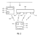
- FIG. 2 shows a block diagram of an HMI system comprising a technical equipment 104 with technical resources and an operating and monitoring device 106 with a transmitting and receiving module according to the invention.
- the technical equipment is eg part of a manufacturing or process engineering device.
- control automation components 102 are present, which intervene on the technical equipment, in particular by switching sensors, positioners and various other so-called "Process Instruments".
- the automation components 102 have, for example, an automation device, such as eg a programmable logic controller 120, which optionally effects the control of the technical equipment in real time.
- the automation components 102 are preferably connected to a bus system 100, e.g. a Profibus, affiliated. This enables universal networking of several automation components 102.
- At least one mobile operating and monitoring device 106 is present. This may e.g. be designed as a wireless hand-held terminal and e.g. have a display and a keyboard 116. Furthermore, emergency, release and acknowledgment keys and key switches can be provided.
- the mobile operating and monitoring device 106 exchanges payload data over a radio link 124 with the automation components 102 of the technical system 104 in a contactless manner.
- An operator using the HMI 106 may thus e.g. Display measured values of the technical system 104 on the display of the operating and monitoring device 106, or enter control commands via the keyboard 116 and send them to the automation components 102.
- the mobile operating device 106 and the automation components 102 For transmission of, for example, measured values and control commands between the mobile operating device 106 and the automation components 102, the mobile operating device 106 and the automation components 102 have corresponding data transmission modules 118, 122.
- This data transmission is preferably implemented by means of radio-frequency (RF) signals.
- RF radio-frequency
- a variety of different data transmission protocols can be used, such as WLAN, IEEE 802.11, Ultra Wide Band (UWB) or BlueTooth protocols.
- the mobile operating device 106 also has a localization module 114, which is designed for transmitting and receiving radar signals. Furthermore, the technical system 104 has at least one transponder. The system preferably has a series of transponders 108, 110, 112, which are attached to the technical system 104 at various reference points. The transponders are designed to modulate and reflect the radar signals emitted by the localization module 114. The radar signals modulated and reflected by the transponders 108, 110, 112 can then be received by the localization module 114 and evaluated for locating the mobile operator device 106. The mobile operating device 106 is thus able to perform a position or distance determination of the transponders 108, 110, 112 automatically. The transponders 108, 110, 112 do not have to carry out a signal evaluation.
- the localization module 114 is equipped with a transmission and reception module described above.
- the radar signals reflected by the transponders can be selectively evaluated.
- Subcarrier modulation thus allows separation of background signals and signals reflected at the transponders.
- a corresponding subcarrier filtering in the localization module 114 therefore, with the aid of the FMCW radar, which is only transmitted for a short time, a clear distance measurement for quasi-stationary destinations can be carried out even with a receiver of only one Real signal evaluation is designed to be implemented in the localization module 114.
- quasi-stationary means that the position of the transponder or the position of the radar system does not change during the measuring time, which is typically in the range of a few ms to a few tens of ms.
- FIG. 3 shows a flowchart of a preferred embodiment of a method according to the invention for distance measurement and data transmission in a continuous wave radar system, in which a transmitting and receiving module and at least one transponder device are arranged.
- a predetermined frequency range is sampled in order to examine this frequency range as to which frequency bands are still free and are not occupied by other devices or systems.
- an unmodulated continuous wave signal having a frequency which lies in a free frequency band is generated.
- a transponder device is searched for using the unmodulated continuous wave signal as a polling signal.
- transponder devices of the continuous wave radar system are set up in such a way that, in response to the interrogation signal, they send a radio answer signal to the transceiver module (step S4).
- step S5 the generation of the unmodulated continuous wave signal is stopped and instead a frequency-modulated continuous wave signal is generated (step S5).
- a distance between the transmitting and receiving module and the transponder device which transmits the radio answer signal is measured in a step S6.
- the unmodulated continuous-wave signal is generated again for a predetermined time, wherein this step can also take place immediately after step S4 (not shown). That is, the unmodulated continuous wave signal is generated again for a predetermined time after the transmitting and receiving module has received a radio answer signal from a transponder device.
Abstract
Description
Die vorliegende Erfindung betrifft ein Verfahren zur Abstandsmessung und Datenübertragung in einem Dauerstrich-Radarsystem. Ferner betrifft die vorliegende Erfindung ein Dauerstrich-Radarsystem mit einem Sende- und Empfangsmodul und mindestens einer Transpondervorrichtung, ein mobiles Bedien- und Beobachtungsgerät sowie ein HMI-System.The present invention relates to a method for distance measurement and data transmission in a continuous wave radar system. Furthermore, the present invention relates to a continuous wave radar system with a transmitting and receiving module and at least one transponder device, a mobile operating and monitoring device and an HMI system.
Radarsysteme eignen sich zur berührungslosen Lokalisierung und Abstandsbestimmung von Objekten. Unter einer Vielzahl verschiedener Radarsysteme ermöglicht z.B. ein frequenzmoduliertes Dauerstrich-Radarsystem, welches auch als Frequency Modulated Continous Wave (FMCW) Radar bezeichnet wird, eine zuverlässige Abstandsbestimmung zwischen Objekten, die auch z.B. nur gering voneinander entfernt sind. Hierbei kommt typischerweise keine gepulste, sondern kontinuierliche, d.h. continuous wave (CW) Radarstrahlung zum Einsatz.Radar systems are suitable for the contactless localization and distance determination of objects. Among a variety of different radar systems, e.g. a frequency modulated continuous wave radar system, also referred to as a Frequency Modulated Continuous Wave (FMCW) radar, provides reliable distance determination between objects which are also e.g. are only slightly separated from each other. Here, typically no pulsed, but continuous, i. E. continuous wave (CW) radar radiation is used.
Beim frequenzmodulierten Dauerstrich-Radarsystem unterliegt die Frequenz der ausgesendeten Radarsignale einer periodischen Modulation, wodurch ausgesendete und von einem Objekt reflektierte Radarsignale beim Wiedereintreffen in das Radarsystem eine Frequenzverschiebung im Vergleich zu den gesendeten Radarsignalen aufweisen, die einem Laufzeitunterschied entspricht. Dieser Laufzeitunterschied gibt den zweifachen Abstand zwischen dem Sende- und Empfangsmodul und dem reflektierenden Objekt wieder.In the continuous wave frequency-modulated radar system, the frequency of the transmitted radar signals is subject to periodic modulation, whereby radar signals emitted and reflected by an object, when entering the radar system, have a frequency shift compared to the transmitted radar signals corresponding to a propagation delay. This difference in transit time represents twice the distance between the transmitting and receiving module and the reflecting object.
Zur Lokalisierung oder Entfernungsbestimmung des reflektierenden Objekts werden empfangene Radarsignale im Empfangsmodul typischerweise einer spektralen Analyse unterzogen. Beispielsweise geben einzelne Peaks oder Spitzen im Leistungsspektrum der Frequenzverschiebung direkt Aufschluss über die Entfernung zwischen dem Sende- und Empfangsmodul und dem reflektierenden Objekt. So entsprechen z.B. große Frequenzverschiebungen großen Laufzeitunterschieden der Radarsignale und somit großen Entfernungen, während kleine Frequenzverschiebungen kleinen Laufzeitunterschieden und somit kleinen Entfernungen entsprechen.For localization or distance determination of the reflecting object, received radar signals in the receiving module are typically subjected to a spectral analysis. For example, individual peaks or peaks in the power spectrum of the frequency shift directly provide information about the distance between the transmitting and receiving module and the reflective Object. For example, large frequency shifts correspond to large transit time differences of the radar signals and thus large distances, while small frequency shifts correspond to small transit time differences and thus small distances.
Der Einsatz eines Radarsystems zur Abstandsbestimmung zu einem bestimmten Objekt ist mitunter problematisch, da vielfältige äußere Faktoren den Empfang reflektierter Radarsignale massiv beeinträchtigen oder stören können. Insbesondere in der Anwesenheit von reflektierenden Metalloberflächen oder Körpern die Radarstrahlen absorbieren ist es nur bedingt möglich, ein empfangenes Radarsignal einem bestimmten reflektierenden Objekt zuzuordnen. Unter Einsatz eines Transponders oder einer Transpondervorrichtung kann dieses Problem zumindest eingeschränkt werden.The use of a radar system to determine the distance to a particular object is sometimes problematic because a variety of external factors can massively affect or interfere with the reception of reflected radar signals. Especially in the presence of reflective metal surfaces or bodies that absorb radar beams, it is only partially possible to associate a received radar signal with a particular reflective object. Using a transponder or a transponder device, this problem can be at least limited.
Eine Transpondervorrichtung ist typischerweise in der Lage ein moduliertes Funkantwortsignal in Reaktion auf ein Abfragesignal zu senden. Ist der Empfänger des Radarsystems auf die Modulation des Funkantwortsignals abgestimmt, so können mit Hilfe geeigneter Filtermethoden die von einer Transpondervorrichtung gesendeten Funkantwortsignale deutlich von Hintergrund- und sonstigen Störsignalen getrennt und zur Abstandsbestimmung ausgewertet werden. Transponder können als passive oder auch als aktive, d.h. leistungsverstärkende Transponder, ausgebildet sein.A transponder device is typically capable of transmitting a modulated radio response signal in response to an interrogation signal. If the receiver of the radar system is tuned to the modulation of the radio answer signal, the radio answer signals transmitted by a transponder device can be clearly separated from background and other interference signals and evaluated for determining the distance with the aid of suitable filter methods. Transponders may be passive or active, i. power amplifying transponder, be formed.
Die von einer Transpondervorrichtung modulierten Funkantwortsignale ermöglichen eine Abstandsbestimmung zwischen der Transpondervorrichtung und dem Empfangsmodul des Radarsystems. Die Verwendung eines einzelnen Transponders erscheint nachteilig insbesondere im Hinblick auf sich fortlaufend ändernde Umgebungsbedingungen. Bewegen sich z.B. der Transponder und das Empfangsmodul des Radarsystems oder befinden sich absorbierende oder abschattende Körper temporär zwischen dem Transponder und dem Empfangsmodul, so ist der Empfang von Funkantwortsignalen sowie das Senden von Abfragesignalen an den Transponder massiv gestört, so dass eine Abstandsbestimmung unter Umständen nicht mehr möglich ist.The radio answer signals modulated by a transponder device allow a distance determination between the transponder device and the receiving module of the radar system. The use of a single transponder appears disadvantageous especially with regard to continuously changing environmental conditions. If, for example, the transponder and the receiving module of the radar system are moving, or if absorbing or shading bodies are temporarily located between the transponder and the receiving module, then the reception of radio answer signals and the transmission of interrogation signals are active the transponder massively disturbed, so that a distance determination may no longer be possible.
Für eine Lokalisierung bzw. Abstandsbestimmung zu einem großen räumlich ausgedehnten Objekt, wie z.B. einer Maschine, ist es daher zweckmäßig, mehrere Transponder um die Maschine herum anzuordnen, um somit zu gewährleisten, dass ein Austausch von Funksignalen zwischen dem Sende- und Empfangsmodul und mindestens einem Transponder jederzeit möglich ist.For a localization to a large spatially extended object, such as e.g. a machine, it is therefore appropriate to arrange several transponders around the machine, so as to ensure that an exchange of radio signals between the transmitting and receiving module and at least one transponder is possible at any time.
Aus dem Stand der Technik ist ein Dauerstrich-Radarsystem mit einer räumlich verteilten Anordnung verschiedener Transponder bekannt, welches ein Funkantwortsignal eindeutig einem der Transponder zuordnen kann. Das Funkantwortsignal wird in dem Transponder einer ersten Modulation unterzogen, so dass das Empfangsmodul eine Abstandsbestimmung zwischen dem Sende- und Empfangsmodul und dem Transponder durchführen kann. Des Weiteren wird das Funkantwortsignal in dem Transponder einer zweiten Modulation unterzogen, um eine Datenübertragung zwischen dem mindestens einen Transponder und dem Sende- und Empfangsmodul durchzuführen. Beispielsweise kann so eine Transponder-ID übertragen werden, um den entsprechenden Transponder eindeutig zu identifizieren.From the prior art, a continuous wave radar system with a spatially distributed arrangement of different transponders is known, which can unambiguously assign a radio answer signal to one of the transponders. The radio answer signal is subjected to a first modulation in the transponder, so that the receiving module can perform a distance determination between the transmitting and receiving module and the transponder. Furthermore, the radio answer signal in the transponder is subjected to a second modulation in order to carry out a data transmission between the at least one transponder and the transmitting and receiving module. For example, such a transponder ID can be transmitted in order to uniquely identify the corresponding transponder.
Dabei ist ein Abfragesignal, welches von dem Sende- und Empfangsmodul ausgesendet wird und in Reaktion auf welches der Transponder das Funkantwortsignal sendet, ein frequenzmoduliertes Dauerstrichsignal (FMCW-Signal). Das heißt, das FMCW-Signal wird sowohl für eine Datenübertragung als auch für eine Abstandsmessung verwendet. Das Abfragesignal wird üblicherweise fortlaufend ausgesendet, um nach Transpondern zu suchen, also auch, wenn keine Transponder zur Kommunikation mit dem Sende- und Empfangsmodul vorhanden sind. Nachdem jedoch die Frequenz eines FMCW-Signals einer periodischen Modulation unterliegt, ist es sehr wahrscheinlich, dass sich benachbarte Sende- und Empfangsmodule, welche durchgehend ein FMCW-Signal aussenden, gegenseitig beeinflussen, so dass keine zuverlässige Abstandsmessung durchführbar ist. Ferner kann ein Sende- und Emfpangsmodul, welches ständig ein FMCW-Signal aussendet, andere Systeme stören, welche im gleichen Frequenzbereich arbeiten, beispielsweise ein WLAN-System. Diese Probleme treten natürlich auch dann auf, wenn das FMCW-Signal nur temporär ausgesendet wird. Außerdem kann ein FMCW-Signal auch eine Datenübertragung in einem Dauerstrich-Radarsystem von einem Transponder zu einem Sende- und Empfangsmodul stören, da das Abfragesignal üblicherweise sehr viel stärker ist als das Funkantwortsignal.In this case, an interrogation signal, which is transmitted by the transmitting and receiving module and in response to which the transponder transmits the radio answer signal, a frequency modulated continuous wave signal (FMCW signal). That is, the FMCW signal is used for both data transmission and distance measurement. The interrogation signal is usually transmitted continuously to search for transponders, so even if no transponder for communication with the transmitting and receiving module are present. However, since the frequency of an FMCW signal is subject to periodic modulation, it is very likely that adjacent transmitting and receiving modules, which continuously transmit an FMCW signal, influence each other, so that reliable distance measurement is not feasible. Furthermore, can a transmitting and receiving module, which constantly emits an FMCW signal disturb other systems that work in the same frequency range, such as a WLAN system. Of course, these problems also occur if the FMCW signal is sent out only temporarily. In addition, an FMCW signal may also interfere with data transmission in a continuous wave radar system from a transponder to a transmitting and receiving module, since the interrogation signal is usually much stronger than the radio answer signal.
Der Erfindung liegt somit die Aufgabe zu Grunde, ein Dauerstrich-Radarsystem so weiterzugestalten, dass eine Abstandsmessung zwischen einer Transpondervorrichtung und einem Sende- und Empfangsmodul sowie eine Datenübertragung von der Transpondervorrichtung zu dem Sende- und Empfangsmodul zuverlässig durchgeführt werden können, insbesondere ohne andere Systeme zu beeinflussen.The invention is therefore based on the object to further develop a continuous wave radar system so that a distance measurement between a transponder device and a transmitting and receiving module and data transmission from the transponder device to the transmitting and receiving module can be reliably performed, in particular without other systems influence.
Die Aufgabe wird mit den Merkmalen der unabhängigen Patentansprüche gelöst. Weitere vorteilhafte Ausführungen der Erfindung sind in den Unteransprüchen angegeben.The object is achieved with the features of the independent claims. Further advantageous embodiments of the invention are specified in the subclaims.
Ein erster Aspekt der vorliegenden Erfindung betrifft ein Verfahren zur Abstandsmessung und Datenübertragung in einem Dauerstrich-Radarsystem, in welchem ein Sende- und Empfangsmodul und mindestens eine Transpondervorrichtung angeordnet sind. Das Sende- und Empfangsmodul erzeugt ein unmoduliertes Dauerstrichsignal mit einer vorbestimmten Frequenz als ein Abfragesignal, mit dessen Hilfe eine Transpondervorrichtung gesucht wird. Nur wenn das Sende- und Empfangsmodul ein Funkantwortsignal von einer Transpondervorrichtung empfängt, welches in Reaktion auf das Abfragesignal erzeugt wird, wird ein frequenzmoduliertes Dauerstrichsignal erzeugt. Mit Hilfe dieses frequenzmodulierten Dauerstrichsignals wird ein Abstand zwischen dem Sende- und Empfangsmodul und der Transpondervorrichtung gemessen, welche das Frequenzantwortsignal an das Sende- und Empfangsmodul sendet.A first aspect of the present invention relates to a method for distance measurement and data transmission in a continuous wave radar system, in which a transmitting and receiving module and at least one transponder device are arranged. The transmitting and receiving module generates an unmodulated continuous wave signal having a predetermined frequency as an interrogation signal by means of which a transponder device is searched. Only when the transmitting and receiving module receives a radio answer signal from a transponder device which is generated in response to the interrogation signal, a frequency modulated continuous wave signal is generated. With the aid of this frequency-modulated continuous wave signal, a distance between the transmitting and receiving module and the transponder device is measured, which transmits the frequency response signal to the transmitting and receiving module.
Erfindungsgemäß werden Transpondervorrichtungen somit mit Hilfe eines unmodulierten Dauerstrichsignals (CW-Signal) gesucht, welches eine vorbestimmte Frequenz hat. Dadurch kann die Frequenz des unmodulierten Dauerstrichsignals so gewählt werden, dass sie in einem Frequenzbereich liegt, der von keinem anderen System verwendet wird. Somit lassen sich Störungen anderer Systeme vermeiden. Des Weiteren wird das frequenzmodulierte Dauerstrichsignal (FMCW-Signal) ausschließlich für eine Abstandsmessung zwischen dem Sende- und Empfangsmodul und der mindestens einen Transpondervorrichtung verwendet, welche beispielsweise durch eine spektrale Analyse und die Bestimmung einer Frequenzverschiebung des Funkantwortsignals bezüglich des ausgesendeten FMCW-Signals durchgeführt wird. Dadurch ist es möglich, dass das FMCW-Signal nur für eine sehr kurze Zeit ausgesendet wird, beispielsweise 10 Millisekunden je Sekunde. Folglich besteht eine nur sehr geringe Wahrscheinlichkeit von Störungen zwischen diesen Systemen, wodurch eine Koexistenz unterschiedlicher Sende- und Empfangsmodule und anderer Systeme, wie z.B. eines WLAN-Systems, deutlich verbessert wird.According to the invention transponder devices are thus searched with the aid of an unmodulated continuous wave signal (CW signal), which has a predetermined frequency. Thereby, the frequency of the unmodulated continuous wave signal can be chosen to be in a frequency range which is not used by any other system. Thus, disturbances of other systems can be avoided. Furthermore, the frequency-modulated continuous wave signal (FMCW signal) is used exclusively for a distance measurement between the transmitting and receiving module and the at least one transponder device, which is performed for example by a spectral analysis and the determination of a frequency shift of the radio answer signal with respect to the transmitted FMCW signal. This makes it possible for the FMCW signal to be transmitted only for a very short time, for example 10 milliseconds per second. As a result, there is only a very low probability of interference between these systems, which causes coexistence of different transmit and receive modules and other systems, e.g. of a WLAN system, is significantly improved.
In einer Ausführungsform der vorliegenden Erfindung umfasst das Sende- und Empfangsmodul einen komplexen (komplexwertigen) Empfänger, welcher eine Decodierung der durch das Funkantwortsignal übertragenen Daten und eine Abstandsmessung basierend auf dem empfangenen Funkantwortsignal durchführt. Dafür umfasst der komplexe Empfänger entsprechende Auswertemittel zur Analyse des komplexen Funkantwortsignals, welche im Stand der Technik bekannt sind.In one embodiment of the present invention, the transmitting and receiving module comprises a complex (complex-valued) receiver which performs decoding of the data transmitted by the radio-response signal and a distance measurement based on the received radio-response signal. For this purpose, the complex receiver comprises corresponding evaluation means for analyzing the complex radio response signal, which are known in the prior art.
In einer alternativen, besonders bevorzugten Ausführungsform der vorliegenden Erfindung wird die Phase des abgestrahlten unmodulierten Dauerstrichsignals gegenüber den Empfangslokaloszillator mit einer vorbestimmten Frequenz vorzugsweise um +/- 90° verschoben. Die Modulationsform ist beispielsweise ein Rechteck, wobei die Modulationsfrequenz beispielsweise ca. 8 kHz beträgt. Im Basisband kann diese zusätzliche Modulationskomponente unterdrückt werden, um so die von einer Transpondervorrichtung übertragenen Daten in dem Sende- und Empfangsmodul zu gewinnen. Die Umstellung der Phase des unmodulierten Dauerstrichsignals mit der Hilfsmodulation von ca. 8 kHz führt zwar zu einer Verschlechterung eines Signal zu Rauschverhältnisses (SNR) um 3 dB im Vergleich zu einem komplexen Empfänger. Dafür kann jedoch das Funkantwortsignal (Backscatter-Signal) der Transpondervorrichtung mit einem reellen Empfänger demoduliert werden, wie nachfolgend noch im Detail beschrieben wird. Im Vergleich zu herkömmlichen reellen Systemen, welche ausschließlich mit einem breitbandigen FMCW-Signal das Funkantwortsignal dekodieren, entsteht im erfindungsgemäßen System kein zusätzlicher Verlust.In an alternative, particularly preferred embodiment of the present invention, the phase of the radiated unmodulated continuous wave signal is preferably shifted by +/- 90 ° with respect to the receiving local oscillator at a predetermined frequency. The modulation form is, for example, a rectangle, the modulation frequency being approximately 8 kHz, for example. In baseband, this additional modulation component can be suppressed, so that of a Transponder device to gain transmitted data in the transmitting and receiving module. The conversion of the phase of the unmodulated continuous wave signal with the auxiliary modulation of about 8 kHz leads to a deterioration of a signal to noise ratio (SNR) by 3 dB compared to a complex receiver. For this, however, the radio answer signal (backscatter signal) of the transponder device can be demodulated with a real receiver, as will be described in detail below. Compared to conventional real systems, which decode the radio answer signal exclusively with a broadband FMCW signal, no additional loss arises in the system according to the invention.
Die Phasenverschiebung kann entweder im Sende- und Empfangsmodul oder in der Transpondervorrichtung implementiert sein.The phase shift can be implemented either in the transmitting and receiving module or in the transponder device.
In einer weiteren Ausführungsform der vorliegenden Erfindung wird die vorbestimmte Frequenz des unmodulierten Dauerstrichsignals während des Suchens einer Transpondervorrichtung umgetastet. Diese Frequenzumtastung erfolgt in der Sende- und Empfangsmodul. Beispielsweise wird die vorbestimmte Frequenz innerhalb des ISM-Bands zwischen 2,400 GHz und 2,483 GHz mit einer Frequenz von beispielweise ca. 4 kHz umgetastet. Damit wird ein eventuelles Fading bekämpft. Ein Vorteil der Verwendung des ISM-Bands für das unmodulierte Dauerstrichsignal besteht darin, dass es lizenzfrei ist und Geräte, welche dieses Band einsetzen, praktisch auf der ganzen Welt ohne eine länderspezifische Einstellung zugelassen werden können.In a further embodiment of the present invention, the predetermined frequency of the unmodulated continuous wave signal is keyed during search of a transponder device. This frequency shift keying takes place in the transmitting and receiving module. For example, the predetermined frequency within the ISM band between 2.400 GHz and 2.483 GHz is keyed at a frequency of, for example, about 4 kHz. This fights a possible fading. An advantage of using the ISM band for the unmodulated continuous wave signal is that it is license-free and that devices using this band can be approved virtually anywhere in the world without a country-specific setting.
Sowohl die Phasenverschiebung als auch die Frequenzumtastung erzeugen jedoch parasitäre Modulationen, welche im Sende- und Empfangsmodul unterdrückt werden müssen. Diese Unterdrückung kann beispielsweise mit Hilfe geeigneter Filter erfolgen, welche jedoch die von der Transpondervorrichtung empfangenen Daten durchlassen müssen. Ferner muss bei der Filterimplementierung auf die Gruppenlaufzeit geachtet werden, um eine Inter Symbol Interference (ISI) zu vermeiden. Beispielhafte Filter, welche sich zur Unterdrückung der parasitären Modulationen eignen, sind beispielsweise ein Boxcar-Filter, ein CIC-Filter oder ein IIR-Filter. Wird in dem Sende- und Empfangsmodul die optionale Frequenzumtastung der Frequenz des unmodulierten Dauerstrichsignals implementiert, so ist das Boxcar-Filter unter den genannten Filtern bevorzugt, da es aufgrund seiner Polstellen sowohl die Phasenmodulation als auch die Frequenzumtastung sehr gut unterdrücken kann. Ist nur die Phasenverschiebung implementiert, entweder in dem Sende- und Empfangsmodul oder in der Transpondervorrichtung, so liefert nach derzeitigen Erkenntnissen das CIC-Filter eine bessere Unterdrückung der parasitären Modulation als das IIR Filter. Jedes der genannten, beispielhaften Filter besitzt dabei die Eigenschaft, dass die von der Transpondervorrichtung in dem Sende- und Empfangsmodul empfangenen Daten problemlos demoduliert werden können.However, both the phase shift and the frequency shift keying produce parasitic modulations, which must be suppressed in the transmitting and receiving module. This suppression can be carried out, for example, by means of suitable filters, which, however, must pass the data received by the transponder device. In addition, the filter implementation must pay attention to the group delay to avoid inter symbol interference (ISI). Exemplary filters suitable for suppression of parasitic modulations are, for example, a boxcar filter, a CIC filter or an IIR filter. If the optional frequency shift keying of the frequency of the unmodulated continuous wave signal is implemented in the transmitting and receiving module, then the boxcar filter is preferred among the filters mentioned because it can very well suppress both the phase modulation and the frequency shift keying on account of its pole positions. If only the phase shift is implemented, either in the transmit and receive module or in the transponder device, according to current findings, the CIC filter provides a better suppression of the parasitic modulation than the IIR filter. Each of the aforementioned exemplary filters has the property that the data received by the transponder device in the transmitting and receiving module can be demodulated without problems.
In einer weiteren bevorzugten Ausführungsform der Erfindung umfasst das Sende- und Empfangsmodul einen Mischer zur Erzeugung eines reellen Signals aus einem empfangenen Funkantwortsignal. Des Weiteren umfasst das Sende- und Empfangsmodul vorzugsweise eine Auswerteeinheit zur Abstandsmessung sowie eine Demodulationseinheit zur Dekodierung der durch das Funkantwortsignal übertragenen Daten, wobei die Abstandsmessung und die Dekodierung basierend auf dem reellen Signal erfolgen. Besonders bevorzugt erfolgt die komplette Signalauswertung empfangener Funkantwortsignale auf der Basis reeller Signale, so dass auf Auswertemittel zur Analyse komplexer Signale verzichtet werden kann. Dies ermöglicht insbesondere, das Sende- und Empfangsmodul platzsparend und kostengünstig zu realisieren.In a further preferred embodiment of the invention, the transmitting and receiving module comprises a mixer for generating a real signal from a received radio answer signal. Furthermore, the transmitting and receiving module preferably comprises an evaluation unit for distance measurement and a demodulation unit for decoding the data transmitted by the radio answer signal, the distance measurement and the decoding being performed based on the real signal. Particularly preferably, the complete signal evaluation of received radio response signals takes place on the basis of real signals, so that evaluation means for analyzing complex signals can be dispensed with. This makes it possible, in particular, to realize the transmitting and receiving module in a space-saving and cost-effective manner.
Der Mischer ist dazu ausgebildet, das empfangene Funkantwortsignal mit dem Sendesignal zu mischen. Das Spektrum eines aus dieser Mischung erhaltenen reellen Nutzsignals kann dann durch die Auswerteeinheit zur Abstandsbestimmung mit FMCW-Signal und zur Datendekodierung mit CW- Signal genutzt werden.The mixer is configured to mix the received radio answer signal with the transmission signal. The spectrum of a real user signal obtained from this mixture can then be used by the evaluation unit for distance determination with FMCW signal and for data decoding with CW signal.
Die Implementierung der reellen Radarsignal-Auswertung ermöglicht eine wesentliche Verringerung der Bauteilgröße und Bauteilkosten im Vergleich zu einer komplexen Auswertung, die eine I/Q Demodulation des empfangenen Radarsignals erfordert. Daher kann durch den Einsatz eines reellen Empfängers und einer reellen Auswerteeinheit eine erforderliche Bauteilgrößenbegrenzung eingehalten werden, beispielsweise für ein mobiles Bedien- und Beobachtungsgerät, welches das obige Sende- und Empfangsmodul eines Dauerstrich-Radarsystems enthält, in welchem ein Suche von Transpondervorrichtungen sowie eine anschließenden Datenübertragung von einer gefundenen Transpondervorrichtung zu dem Sende- und Empfangsmodul mit Hilfe eines unmodulierten Dauerstrichsignals durchgeführt wird. Zudem ermöglicht die reelle Implementierung der Empfangsmittel und Auswertemittel eine Kosteneinsparung.The implementation of the real radar signal evaluation allows a significant reduction in component size and component cost compared to a complex evaluation that requires I / Q demodulation of the received radar signal. Therefore, by using a real receiver and a real evaluation unit, a required component size limitation can be maintained, for example, for a mobile operating and monitoring device which includes the above transmitting and receiving module of a continuous wave radar system, in which a search of transponder devices and a subsequent data transmission is performed from a found transponder device to the transmitting and receiving module by means of an unmodulated continuous wave signal. In addition, the real implementation of the receiving means and evaluation means allows cost savings.
In einer noch weiteren Ausführungsform der vorliegenden Erfindung wird ein vorbestimmter Frequenzbereich, beispielsweise das ISM-Band zwischen 2,400 GHz und 2,483 GHz, abgetastet, bevor das unmodulierte Dauerstrichsignal als ein Abfragesignal erzeugt wird. Dadurch kann sichergestellt werden, dass für die Frequenz des unmodulierten Dauerstrichsignals eine freie Frequenz in dem abgetasteten Frequenzbereich gewählt wird, das heißt eine Frequenz, die nicht belegt ist. Mit anderen Worten wird ein Spektrum-Monitoring durchgeführt, bevor das unmodulierte Dauerstrichsignal mit einer vorbestimmten Frequenz erzeugt wird. Denn gerade im ISM-Band arbeitet eine Vielzahl von Geräten, beispielsweise WLAN-Geräte, wodurch ohne eine vorherige Abtastung die Gefahr besteht, dass eine bereits belegte Frequenz für das unmodulierte Dauerstrichsignal ausgewählt wird. Somit kann eine Wahrscheinlichkeit, dass das Sende- und Empfangsmodul andere Geräte stört beziehungsweise durch andere Geräte gestört wird, deutlich reduziert werden.In yet another embodiment of the present invention, a predetermined frequency range, for example the ISM band between 2.400 GHz and 2.483 GHz, is sampled before the unmodulated continuous wave signal is generated as an interrogation signal. It can thereby be ensured that a free frequency in the sampled frequency range is selected for the frequency of the unmodulated continuous wave signal, that is to say a frequency which is not occupied. In other words, spectrum monitoring is performed before the unmodulated continuous wave signal is generated at a predetermined frequency. Because just in the ISM band works a variety of devices, such as wireless devices, which without a previous scan the risk that an already occupied frequency for the unmodulated continuous wave signal is selected. Thus, a probability that the transmitting and receiving module disturbs other devices or is disturbed by other devices can be significantly reduced.
In einer noch weiteren Ausführungsform der vorliegenden Erfindung ist das Sende- und Empfangsmodul eingerichtet, um das unmodulierte Dauerstrichsignal nach erfolgter Datendekodierung und/oder erfolgter Abstandsmessung für eine vorbestimmte Zeit erneut zu erzeugen. Das heißt, sobald die Datendekodierung mittels CW- Signal und/oder die Abstandsmessung mittels des FMCW-Signals abgeschlossen ist, beispielsweise nach 10 Millisekunden, wird das FMCW-Signal abgeschaltet und erneut ein CW-Signal erzeugt. Dieser Schritt kann beispielsweise durch die Eigenschaften des Sende- und Empfangsmoduls bedingt sein. Jedoch wird auch dieses CW-Signal nach einer vorbestimmten Zeit abgestellt, um eine unnötige Aussendung des CW-Signals zu vermeiden. Dadurch wird die Koexistenz noch weiter verbessert.In yet another embodiment of the present invention, the transmit and receive module is configured to receive the unmodulated continuous wave signal after data decoding and / or distance measurement for a predetermined one To generate time again. That is, once the data decoding is completed by means of the CW signal and / or the distance measurement by means of the FMCW signal, for example after 10 milliseconds, the FMCW signal is switched off and a CW signal is generated again. This step may be due, for example, to the characteristics of the transmitting and receiving module. However, this CW signal is also turned off after a predetermined time to avoid unnecessary transmission of the CW signal. This will further enhance coexistence.
Ein weiterer Aspekt der vorliegenden Erfindung betrifft ein mobiles Bedien- und Beobachtungsgerät für die Automatisierungskomponenten einer technischen Anlage, welches ein oben beschriebenes Sende- und Empfangsmodul umfasst. Zur Vermeidung einer Steuerung des Automatisierungssystems durch das mobile Bedien- und Beobachtungsgerät aus einer unzulässigen Entfernung ist es vorteilhaft, das Bedien- und Beobachtungsgerät zu lokalisieren und abhängig von seiner Position sicherheitsrelevante Bedienungen der technischen Anlage freizugeben oder zu deaktivieren. Dazu wird die Abstandsmessung durchgeführt, um detektieren zu können, ob sich das mobile Bedien- und Beobachtungsgerät innerhalb eines aktiven Bedienbereichs befindet.Another aspect of the present invention relates to a mobile operating and monitoring device for the automation components of a technical system, which comprises a transmission and reception module described above. To avoid control of the automation system by the mobile operating and monitoring device from an impermissible distance, it is advantageous to locate the operating and monitoring device and release depending on its position safety-related operations of the technical system or disable. For this purpose, the distance measurement is performed in order to be able to detect whether the mobile operating and monitoring device is located within an active operating area.
Ein noch weiterer Aspekt der vorliegenden Erfindung betrifft ein HMI (Human Machine Interface) System, umfassend mindestens ein solches mobiles Bedien- und Beobachtungsgerät. Der Begriff HMI Gerät ist ein Oberbegriff und umfasst alle zu dieser Gruppe von Geräten gehörigen Komponenten. Als ein Beispiel sollen "Operator Panels", auch als "Bedienpanels" bzw. kurz als "OP" bezeichnet, genannt werden. Diese können stationär oder mobil ausgeführt sein. HMI Geräte dienen in einer vernetzten Automatisierung als Hilfsmittel für Bedienpersonal, um Prozessdaten der zu steuernden technischen Anlage anzeigen oder bedienen zu können. Diese Funktion wird mit "Supervisor Control and Data Akquisition"(SCADA) bezeichnet. Hierzu ist das HMI Gerät in der Regel hardwaremäßig speziell aufgebaut, d.h. es verfügt z.B. über einen Touchscreen und ist gegen Umwelteinflüsse besonders abgeschirmt. Weiterhin wird darin eine spezielle Software ausgeführt. Diese stellt Funktionen bereit, womit Komfort, Qualität und Sicherheit einer Bedienung durch eine Bedienperson verbessert werden. So können über HMI Geräte z.B. interaktive Prozessabbilder der zu bedienenden technischen Anlage visualisiert, bedient, projektiert und generiert werden. Hiermit ist einerseits eine selektive Anzeige von Reaktionen der technischen Anlage möglich, meist in Form von Messwerten und Meldungen. Andererseits wird es durch gezielte Vorgabe von Bedienhandlungen und Dateneingaben ermöglicht, die technische Anlage in gewünschte Zustände zu überführen.Yet another aspect of the present invention relates to an HMI (Human Machine Interface) system comprising at least one such mobile operator control and monitoring device. The term HMI device is a generic term and includes all components belonging to this group of devices. As an example, "operator panels", also referred to as "control panels" or briefly referred to as "OP" to be called. These can be stationary or mobile. HMI devices are used in a networked automation as a tool for operating personnel to view or operate process data of the technical system to be controlled. This feature is called "Supervisor Control and Data Acquisition" (SCADA). For this purpose, the HMI device is usually hardware-specific It has, for example, a touch screen and is particularly shielded against environmental influences. Furthermore, it runs a special software. This provides functions that improve comfort, quality and safety of operator operation. For example, HMI devices can be used to visualize, operate, configure and generate interactive process images of the technical system to be operated. On the one hand, a selective display of reactions of the technical system is possible on the one hand, mostly in the form of measured values and messages. On the other hand, it is made possible by targeted specification of operator actions and data entries to convert the technical system into desired states.
Bevorzugte Ausführungsbeispiele der Erfindung werden nachfolgend anhand der Zeichnungen näher erläutert.
- Figur 1
- zeigt ein Blockdiagramm eines Dauerstrich-Radarsystems;
- Figur 2
- zeigt ein Blockdiagramm eines HMI-Systems;
- Figur 3
- zeigt ein Flussdiagramm eines erfindungsgemäßen Verfahrens.
- FIG. 1
- shows a block diagram of a continuous wave radar system;
- FIG. 2
- shows a block diagram of an HMI system;
- FIG. 3
- shows a flowchart of a method according to the invention.
Das Abfragesignal ist ein unmoduliertes Dauerstrichsignal (CW-Signal). Allerdings sendet das Sende- und Empfangsmodul 12 ein frequenzmoduliertes Dauerstrichsignal (FMCW-Signal) anstelle des unmodulierten Dauerstrichsignals aus, sobald ein Transponder ein Funkantwortsignal in Reaktion auf das Abfragesignal gesendet hat. Mit Hilfe des frequenzmodulierten Signals wird dann eine Abstandsmessung zwischen dem Transponder und dem Sende- und Empfangsmodul 12 durchgeführt. D. h., eine Daten- bzw. Informationsübertragung von dem Transponder an das Sende- und Emfpangsmodul und eine Abstandsmessung zwischen diesen werden sequentiell durchgeführt, wobei das FMCW-Signal ausschließlich zur Abstandsmessung verwendet wird.The interrogation signal is an unmodulated continuous wave signal (CW signal). However, the
Für eine bessere Unterscheidung zwischen Funkantwortsignalen und Signalen, die an anderen beliebigen Objekten reflektiert werden, unterliegen die von den Transpondern 14, 16, 18 ausgesendeten Funkantwortsignale einer ersten Modulation mit einer Subträgerfrequenz (z.B. 450 kHz). Die so modulierten Funkantwortsignale werden im Sende- und Empfangsmodul 12 mit dem Abfragesignal gemischt und somit auf die Subträgerfrequenz umgesetzt. Mit entsprechenden Filtern können somit störende Hintergrundsignale effektiv beseitigt werden.For a better discrimination between radio answer signals and signals reflected at other arbitrary objects, the radio answer signals emitted by the
Diese erste Subträgermodulation wird in allen drei Transpondern 14, 16, 18 gleichermaßen durchgeführt. Sie erlaubt lediglich eine Trennung zwischen Signalen, die von Transpondern ausgesendet werden und Signalen, die z.B. an Metalloberflächen reflektiert werden. Typischerweise wird das Dauerstrich-Radarsystem zur Lokalisierung des Sende- und Empfangsmoduls verwendet. Hierzu befinden sich die Transponder 14, 16, 18 an vorbestimmten Referenzpunkten und sind räumlich voneinander getrennt. Da nun mit Hilfe der ersten Modulation auf Basis empfangener Funkantwortsignale nicht unterschieden werden kann, von welchem der drei Transponder 14, 16, 18 ein empfangenes Funkantwortsignal ausgesendet wird, werden die Funkantwortsignale einer zweiten Modulation unterzogen, die eine Datenübertragung zwischen einer Transpondervorrichtung 14, 16, 18 und dem Sende- und Empfangsmodul 12 ermöglicht.This first subcarrier modulation is performed equally in all three
Typischerweise erfolgt diese zweite Modulation in Systemen mit reeller Signalverarbeitung mittels Amplitudenmodulation, wie z.B. einer On/Off-Keying Modulation (OOK), da Phasenmodulationen nur mit komplexen Signalverarbeitungsverfahren effizient demoduliert werden können. Diese ermöglicht, dass das Funkantwortsignal mit einer binären Sequenz ein- oder ausgeschaltet wird. Somit kann ein informationstragender zeitlicher Code auf der Basis des Funkantwortsignals von einer der Transpondervorrichtungen 14, 16, 18 zum Sende- und Empfangsmodul 12 übertragen werden. Die codierte Information enthält vorzugsweise einen Identifizierungscode, der für jede Transpondervorrichtung 14, 16, 18 fest vorgegeben ist. Das Sende- und Empfangsmodul verfügt über entsprechende Demodulationsmittel und ist daher in der Lage, ein empfangenes Funkantwortsignal eindeutig einer der drei gezeigten Transpondervorrichtungen 14, 16, 18 zuzuordnen.Typically, this second modulation is done in real signal processing systems by amplitude modulation, such as, e.g. On / Off Keying Modulation (OOK), since phase modulations can only be efficiently demodulated with complex signal processing techniques. This allows the radio answer signal to be turned on or off with a binary sequence. Thus, an information-bearing temporal code based on the radio answer signal may be transmitted from one of the
Werden z.B. mehrere Funkantwortsignale von verschiedenen Transpondern 14, 16, 18 empfangen und ausgewertet, so können die gewonnenen Abstandsdaten unter Kenntnis der Positionen der einzelnen Transponder 14, 16, 18 für eine genaue Lokalisierung oder Positionsbestimmung des Sende- und Empfangsmoduls effektiv genutzt werden.If e.g. a plurality of radio answer signals from
Ein weiterer Vorteil des Dauerstrich-Radarsystems gemäß dem dargestellten Ausführungsbeispiel besteht darin, dass selbst bei einer Unterbrechung oder teilweisen Abschattung einer Funkübertragung zwischen dem Sende- und Empfangsmodul 12 und z.B. dem Transponder 18, nach wie vor Funkantwortsignale von den verbleibenden Transpondern 14 und 16 empfangen und ausgewertet werden können. Das Dauerstrich-Radarsystem erfordert lediglich den Empfang von Funkantwortsignalen von mindestens einem Transponder, um zumindest einen Abstand zwischen Sende- und Empfangsmodul 12 und einem der Transponder 14, 16, 18 berechnen zu können.Another advantage of the continuous wave radar system according to the illustrated embodiment is that even with interruption or partial shadowing of a radio transmission between the transmitting and receiving
Die Automatisierungskomponenten 102 sind vorzugsweise an ein Bussystem 100, wie z.B. einen Profibus, angegliedert. Dies ermöglicht eine universelle Vernetzung mehrerer Automatisierungskomponenten 102.The
Zur Bedienung und Beobachtung der Automatisierungskomponenten 102 und z.B. von deren ablaufenden Steuerungs-, Diagnose-, Alarmverarbeitungs- und Langzeitbeobachtungsprozessen ist zumindest ein mobiles Bedien- und Beobachtungsgerät 106 vorhanden. Dieses kann z.B. als ein kabelloses Hand-Held Terminal ausgeführt sein und z.B. über ein Display und eine Tastatur 116 verfügen. Weiterhin können Not-, Aus- und Quittungstasten und Schlüsselschalter vorgesehen sein. Das mobile Bedien- und Beobachtungsgerät 106 tauscht in einer berührungslosen Weise Nutzdaten über eine Funkstrecke 124 mit den Automatisierungskomponenten 102 der technischen Anlage 104 aus. Eine Bedienperson, die das Bedien- und Beobachtungsgerät 106 gebraucht, kann sich somit z.B. Messwerte von der technischen Anlage 104 auf dem Display des Bedien- und Beobachtungsgeräts 106 anzeigen lassen, bzw. Steuerbefehle über dessen Tastatur 116 eingeben und diese an die Automatisierungskomponenten 102 senden.To operate and observe the
Zur Übermittlung von z.B. Messwerten und Steuerbefehlen zwischen dem mobilen Bediengerät 106 und den Automatisierungskomponenten 102 verfügen das mobile Bediengerät 106 sowie die Automatisierungskomponenten 102 über entsprechende Datenübertragungsmodule 118, 122. Diese Datenübertragung wird vorzugsweise mit Hilfe von Radiofrequenz (RF) Signalen realisiert. Hierbei können eine Vielzahl von verschiedenen Datenübertragungsprotokollen, wie z.B. WLAN, IEEE 802.11, Ultra Wide Band (UWB) oder BlueTooth Protokolle zum Einsatz kommen.For transmission of, for example, measured values and control commands between the
Das mobile Bediengerät 106 verfügt zudem über ein Lokalisierungsmodul 114, das zum Senden und zum Empfangen von Radarsignalen ausgebildet ist. Ferner verfügt die technische Anlage 104 über mindestens einen Transponder. Vorzugsweise verfügt die Anlage über eine Reihe von Transpondern 108, 110, 112, die an verschiedenen Referenzpunkten an der technischen Anlage 104 angebracht sind. Die Transponder sind dazu ausgebildet, die vom Lokalisierungsmodul 114 ausgesendeten Radarsignale zu modulieren und zu reflektieren. Die von den Transpondern 108, 110, 112 modulierten und reflektierten Radarsignale können dann von dem Lokalisierungsmodul 114 empfangen und zur Lokalisierung des mobilen Bediengeräts 106 ausgewertet werden. Das mobile Bediengerät 106 ist somit in der Lage, eine Positions- oder Abstandsbestimmung von den Transpondern 108, 110, 112 selbsttätig durchzuführen. Die Transponder 108, 110, 112 müssen hierbei keine Signalauswertung vornehmen.The
In einer erfindungsgemäßen Weiterbildung des HMI-Systems ist das Lokalisierungsmodul 114 mit einem oben beschriebenen Sende- und Empfangsmodul ausgestattet. Mittels einer von den Transpondern 108, 110, 112 durchgeführten Subträger-Modulation können die von den Transpondern reflektierten Radarsignale selektiv ausgewertet werden. Die Subträger-Modulation ermöglicht somit eine Trennung von Hintergrundsignalen und Signalen, die an den Transpondern reflektiert wurden. Durch eine entsprechende Subträger-Filterung im Lokalisierungsmodul 114 kann somit mit Hilfe des nur kurzzeitig ausgesendeten FMCW-Radars eine eindeutige Entfernungsmessung für quasistationäre Ziele sogar mit einem Empfänger der lediglich für eine reelle Signalauswerten ausgelegt ist im Lokalisierungsmodul 114 realisiert werden.In an embodiment of the HMI system according to the invention, the
Quasistationär bedeutet in diesem Zusammenhang, dass während der Messzeit, die typischerweise im Bereich einiger ms bis einiger 10 ms liegt, sich die Position der Transponder bzw. die Position des Radarsystems nicht verändert.In this context, quasi-stationary means that the position of the transponder or the position of the radar system does not change during the measuring time, which is typically in the range of a few ms to a few tens of ms.
Sobald das Sende- und Empfangsmodul ein Funkantwortsignal empfängt, wird das Erzeugen des unmodulierten Dauerstrichsignals gestoppt und anstelle dessen ein frequenzmoduliertes Dauerstrichsignal erzeugt (Schritt S5). Mit Hilfe des frequenzmodulierten Dauerstrichsignals wird in einem Schritt S6 ein Abstand zwischen dem Sende- und Empfangsmodul und der Transpondervorrichtung gemessen, welche das Funkantwortsignal sendet. Vorzugsweise wird nach einer erfolgten Abstandsmessung in einem Schritt S7 das unmodulierte Dauerstrichsignal für eine vorbestimmte Zeit erneut erzeugt, wobei dieser Schritt auch unmittelbar nach Schritt S4 erfolgen kann (nicht dargestellt). Das heißt, das unmodulierte Dauerstrichsignal wird für eine vorbestimmte Zeit erneut erzeugt, nachdem das Sende- und Empfangsmodul ein Funkantwortsignal von einer Transpondervorrichtung empfangen hat. Dies ist dann vorteilhaft, wenn ein Transponder das Funkantwortsignal sendet, welcher in der aktuellen Anwendung keine beziehungsweise keine ausschlaggebende Rolle spielt. So kann eine unnötige Abstandsmessung zu diesem Transponder umgangen und anstatt dessen direkt mit einer erneuten Suche nach einem relevanten Transponder begonnen werden.As soon as the transmitting and receiving module receives a radio answer signal, the generation of the unmodulated continuous wave signal is stopped and instead a frequency-modulated continuous wave signal is generated (step S5). With the aid of the frequency-modulated continuous wave signal, a distance between the transmitting and receiving module and the transponder device which transmits the radio answer signal is measured in a step S6. Preferably, after a distance measurement has been carried out in a step S7, the unmodulated continuous-wave signal is generated again for a predetermined time, wherein this step can also take place immediately after step S4 (not shown). That is, the unmodulated continuous wave signal is generated again for a predetermined time after the transmitting and receiving module has received a radio answer signal from a transponder device. This is advantageous when a transponder transmits the radio answer signal, which plays no role in the current application or no decisive role. Thus, an unnecessary distance measurement can be bypassed to this transponder and instead be started directly with a new search for a relevant transponder.
Claims (28)
Priority Applications (3)
| Application Number | Priority Date | Filing Date | Title |
|---|---|---|---|
| EP08010824A EP2133711B1 (en) | 2008-06-13 | 2008-06-13 | Method for distance measuring and data transfer in a continuous wave radar system |
| US12/482,667 US8102303B2 (en) | 2008-06-13 | 2009-06-11 | Method for distance measurement and data transmission in a continuous wave radar system |
| CN200910149031.2A CN101604022B (en) | 2008-06-13 | 2009-06-12 | The method of range finding and transmission data in continuous-wave radar system |
Applications Claiming Priority (1)
| Application Number | Priority Date | Filing Date | Title |
|---|---|---|---|
| EP08010824A EP2133711B1 (en) | 2008-06-13 | 2008-06-13 | Method for distance measuring and data transfer in a continuous wave radar system |
Publications (2)
| Publication Number | Publication Date |
|---|---|
| EP2133711A1 true EP2133711A1 (en) | 2009-12-16 |
| EP2133711B1 EP2133711B1 (en) | 2013-02-27 |
Family
ID=40091325
Family Applications (1)
| Application Number | Title | Priority Date | Filing Date |
|---|---|---|---|
| EP08010824A Active EP2133711B1 (en) | 2008-06-13 | 2008-06-13 | Method for distance measuring and data transfer in a continuous wave radar system |
Country Status (3)
| Country | Link |
|---|---|
| US (1) | US8102303B2 (en) |
| EP (1) | EP2133711B1 (en) |
| CN (1) | CN101604022B (en) |
Families Citing this family (22)
| Publication number | Priority date | Publication date | Assignee | Title |
|---|---|---|---|---|
| WO2010001354A1 (en) * | 2008-07-02 | 2010-01-07 | Nxp B.V. | A system for reading information transmitted from a transponder |
| US8446253B2 (en) * | 2009-03-11 | 2013-05-21 | Checkpoint Systems, Inc. | Localization using virtual antenna arrays in modulated backscatter RFID systems |
| FI122310B (en) | 2010-04-09 | 2011-11-30 | Teknologian Tutkimuskeskus Vtt | Procedure, systems and computer software for remote measurement of RFID identifiers |
| WO2012061765A1 (en) | 2010-11-05 | 2012-05-10 | Interdigital Patent Holdings, Inc. | Wtru measurements handling to mitigate in-device interference |
| CN102788974B (en) * | 2011-05-17 | 2014-05-07 | 苏州市江海通讯发展实业有限公司 | Accurate positioning method of radar responder |
| CN102788971B (en) * | 2011-05-17 | 2014-05-28 | 苏州市江海通讯发展实业有限公司 | Method for correcting positioning accuracy of radar responder |
| CN103185882B (en) * | 2011-12-29 | 2015-03-11 | 中国移动通信集团公司 | Measuring method of relative position, device of relative position and system of relative position |
| DE102013213345A1 (en) * | 2013-07-08 | 2015-01-08 | Vega Grieshaber Kg | Universal data acquisition in waters |
| US9709672B2 (en) * | 2013-08-16 | 2017-07-18 | Drnc Holdings, Inc. | Method and system for identifying and finding a range of an object |
| US9702970B2 (en) * | 2013-08-30 | 2017-07-11 | Maxim Integrated Products, Inc. | Time of arrival delay cancellations |
| US9958533B2 (en) | 2013-09-06 | 2018-05-01 | Drnc Holdings, Inc. | Method and system for locating wireless devices within a local region |
| US9791550B2 (en) * | 2014-07-23 | 2017-10-17 | Honeywell International Inc. | Frequency-Modulated-Continuous-Wave (FMCW) radar with timing synchronization |
| EP3198736A4 (en) | 2014-09-22 | 2018-05-23 | DRNC Holdings, Inc. | Transmission apparatus for a wireless device using delta-sigma modulation |
| US10067221B2 (en) * | 2015-04-06 | 2018-09-04 | Texas Instruments Incorporated | Interference detection in a frequency modulated continuous wave (FMCW) radar system |
| DE102015216220B4 (en) * | 2015-08-25 | 2018-05-03 | Continental Automotive Gmbh | Driver for communication with a transponder, in particular driver for installation in a motor vehicle and for quasi-resonant communication with a mobile transponder for a vehicle access and / or start system of a motor vehicle |
| CN106162703B (en) * | 2016-08-19 | 2019-04-16 | 张慧 | A kind of wireless lan communication system for ranging and range rate |
| LU100528B1 (en) * | 2017-12-01 | 2019-06-12 | Iee Sa | Radar System Operating Method and Radar System Having Improved Range Resolution by Mutually Delayed Orthogonal Codes |
| US11204410B2 (en) * | 2019-02-11 | 2021-12-21 | Nxp B.V. | Radar-based communication |
| JP7293488B2 (en) * | 2019-07-09 | 2023-06-19 | シーメンス インダストリー ソフトウェア エヌヴェ | How to simulate a continuous wave lidar sensor |
| US11550027B2 (en) | 2020-05-04 | 2023-01-10 | Nxp B.V. | Predistortion technique for joint radar/communication systems |
| CN112512177A (en) * | 2020-11-06 | 2021-03-16 | 南京大学 | Area array light source driving method of continuous wave imaging radar |
| CN114935754A (en) * | 2022-07-20 | 2022-08-23 | 深圳芯盛思技术有限公司 | Frequency modulation continuous wave radar modulation system adopting digital modulation technology and use method |
Citations (6)
| Publication number | Priority date | Publication date | Assignee | Title |
|---|---|---|---|---|
| US5712639A (en) * | 1995-09-19 | 1998-01-27 | Thomson-Csf | Method for the localizing of a transceiver of data packets |
| US5796362A (en) * | 1994-06-13 | 1998-08-18 | Hittite Microwave Corporation | Post launch on-board identification friend or foe system |
| US20030034887A1 (en) * | 2001-03-12 | 2003-02-20 | Crabtree Timothy L. | Article locator system |
| US6868073B1 (en) | 2000-06-06 | 2005-03-15 | Battelle Memorial Institute K1-53 | Distance/ranging by determination of RF phase delta |
| EP1760626A2 (en) * | 2005-08-30 | 2007-03-07 | Fujitsu Ltd. | RFID interrogator and data communication method thereof |
| EP1903412A1 (en) | 2006-09-22 | 2008-03-26 | Siemens Aktiengesellschaft | Method for releasing the operation of automation components of a technical installation via a mobile control and visualisation apparatus |
Family Cites Families (10)
| Publication number | Priority date | Publication date | Assignee | Title |
|---|---|---|---|---|
| US2903691A (en) * | 1946-02-01 | 1959-09-08 | Rossi Bruno | Range tracking circuit |
| US5153836A (en) * | 1990-08-22 | 1992-10-06 | Edward J. Fraughton | Universal dynamic navigation, surveillance, emergency location, and collision avoidance system and method |
| US6570913B1 (en) * | 1999-04-05 | 2003-05-27 | Cisco Technology, Inc. | Method and apparatus for selecting optimum frequency for upstream data transmission in a network system utilizing cable modems |
| DE10210037A1 (en) * | 2002-03-07 | 2003-10-02 | Siemens Ag | Active backscatter transponder, communication system with such an and method for transmitting data with such an active backscatter transponder |
| US6998557B2 (en) * | 2003-08-29 | 2006-02-14 | Premark Feg L.L.C. | Power driven food machine and related multi-action switch assembly |
| GB0325622D0 (en) * | 2003-11-03 | 2003-12-10 | Cambridge Consultants | System for determining positional information |
| US7030761B2 (en) * | 2004-03-16 | 2006-04-18 | Symbol Technologies | Multi-resolution object location system and method |
| US7479884B1 (en) * | 2004-08-31 | 2009-01-20 | Cedar Ridge Research | System and method for monitoring objects, people, animals or places |
| JP2006108766A (en) * | 2004-09-30 | 2006-04-20 | Fuji Xerox Co Ltd | Wireless responder and image forming apparatus |
| BRPI0520544A2 (en) * | 2005-11-24 | 2009-05-12 | Nokia Corp | methodology, module, terminal and system enabling scheduled operation of a radio frequency identification (rfdi) subsystem and a wireless communication subsystem |
-
2008
- 2008-06-13 EP EP08010824A patent/EP2133711B1/en active Active
-
2009
- 2009-06-11 US US12/482,667 patent/US8102303B2/en active Active
- 2009-06-12 CN CN200910149031.2A patent/CN101604022B/en active Active
Patent Citations (6)
| Publication number | Priority date | Publication date | Assignee | Title |
|---|---|---|---|---|
| US5796362A (en) * | 1994-06-13 | 1998-08-18 | Hittite Microwave Corporation | Post launch on-board identification friend or foe system |
| US5712639A (en) * | 1995-09-19 | 1998-01-27 | Thomson-Csf | Method for the localizing of a transceiver of data packets |
| US6868073B1 (en) | 2000-06-06 | 2005-03-15 | Battelle Memorial Institute K1-53 | Distance/ranging by determination of RF phase delta |
| US20030034887A1 (en) * | 2001-03-12 | 2003-02-20 | Crabtree Timothy L. | Article locator system |
| EP1760626A2 (en) * | 2005-08-30 | 2007-03-07 | Fujitsu Ltd. | RFID interrogator and data communication method thereof |
| EP1903412A1 (en) | 2006-09-22 | 2008-03-26 | Siemens Aktiengesellschaft | Method for releasing the operation of automation components of a technical installation via a mobile control and visualisation apparatus |
Non-Patent Citations (2)
| Title |
|---|
| KONNO K ET AL: "60 GHz Millimeter-Wave Dual Mode Radar for IVHS", TOPICAL SYMPOSIUM ON MILLIMETER WAVES, 1997, KANAGAWA, JAPAN, 7-8 JULY 1997, NEW YORK, NY, USA,IEEE, US, 7 July 1997 (1997-07-07), pages 159 - 161, XP010289054, ISBN: 978-0-7803-3887-6 * |
| KONNO K ET: "60 GHz Millimeter-Wave Dual Mode Radar for IVHS", TOPICAL SYMPOSIUM ON MILLIMETER WAVES, 7 July 1997 (1997-07-07), pages 159 - 161 |
Also Published As
| Publication number | Publication date |
|---|---|
| CN101604022A (en) | 2009-12-16 |
| US20090309780A1 (en) | 2009-12-17 |
| CN101604022B (en) | 2015-11-25 |
| EP2133711B1 (en) | 2013-02-27 |
| US8102303B2 (en) | 2012-01-24 |
Similar Documents
| Publication | Publication Date | Title |
|---|---|---|
| EP2133711B1 (en) | Method for distance measuring and data transfer in a continuous wave radar system | |
| EP1903412B1 (en) | Method for releasing the operation of automation components of a technical installation via a mobile control and visualisation apparatus | |
| DE102017216435B4 (en) | Method for operating radar sensors and motor vehicles | |
| EP3139139B1 (en) | Fill level measuring device with detection mode for interfering signals | |
| DE112019001466T5 (en) | Distance measuring system | |
| DE102015118121A1 (en) | MULTIPLE TRANSMITTER AND ANTENNA VERIFICATION SYSTEM | |
| WO2018197116A1 (en) | Method for operating authentication system and authentication system | |
| EP1719067A1 (en) | Method for the operation of rfid read/write devices | |
| EP0243885B1 (en) | Method and apparatus for setting up a short wave radio network communication | |
| EP1672445B1 (en) | HMI system with a mobile operating and monitoring device for operations critical to safety of a technical installation | |
| EP1681581B1 (en) | Distance measuring system for determining a distance range | |
| EP1681578A1 (en) | Noise suppression for a radar system | |
| EP1655684B1 (en) | Reader for non-contact reading of transponder data | |
| EP1672386B1 (en) | Continuous wave radarsystem for distance measurements and data transmission | |
| EP2850739B1 (en) | Method for radio transmission by ultra-wideband-transmission | |
| DE10163653A1 (en) | Device for radar system e.g. for speed control in vehicle, uses demodulated reception signals specifically as input signals for device | |
| DE10005503C2 (en) | Process for increasing manipulation security in a bidirectional, contactless data transmission | |
| EP1672385A1 (en) | Production and processing plant with a transponder device | |
| DE102005046172B4 (en) | Access control system with carrier phase signal evaluation | |
| EP1672387B1 (en) | Radarsystem for locating a mobile control device | |
| EP2656528A1 (en) | Method for operating an electronic reconnaissance system in surroundings that are protected by a jammer | |
| EP1672380B1 (en) | HMI-System with integrated transmit and receive concept | |
| DE102022111492A1 (en) | Method and system for disrupting an unmanned aircraft | |
| EP2362553B1 (en) | Method for determining a transmission channel for an RFID system | |
| DE102022127451A1 (en) | IN-VEHICLE ULTRA WIDEBAND SYSTEM AND METHOD |
Legal Events
| Date | Code | Title | Description |
|---|---|---|---|
| PUAI | Public reference made under article 153(3) epc to a published international application that has entered the european phase |
Free format text: ORIGINAL CODE: 0009012 |
|
| AK | Designated contracting states |
Kind code of ref document: A1 Designated state(s): AT BE BG CH CY CZ DE DK EE ES FI FR GB GR HR HU IE IS IT LI LT LU LV MC MT NL NO PL PT RO SE SI SK TR |
|
| AX | Request for extension of the european patent |
Extension state: AL BA MK RS |
|
| 17P | Request for examination filed |
Effective date: 20100607 |
|
| AKX | Designation fees paid |
Designated state(s): DE FR GB IT |
|
| 17Q | First examination report despatched |
Effective date: 20110216 |
|
| GRAP | Despatch of communication of intention to grant a patent |
Free format text: ORIGINAL CODE: EPIDOSNIGR1 |
|
| GRAS | Grant fee paid |
Free format text: ORIGINAL CODE: EPIDOSNIGR3 |
|
| GRAA | (expected) grant |
Free format text: ORIGINAL CODE: 0009210 |
|
| AK | Designated contracting states |
Kind code of ref document: B1 Designated state(s): DE FR GB IT |
|
| REG | Reference to a national code |
Ref country code: GB Ref legal event code: FG4D Free format text: NOT ENGLISH |
|
| RAP2 | Party data changed (patent owner data changed or rights of a patent transferred) |
Owner name: SIEMENS AKTIENGESELLSCHAFT |
|
| REG | Reference to a national code |
Ref country code: DE Ref legal event code: R096 Ref document number: 502008009306 Country of ref document: DE Effective date: 20130425 |
|
| PLBE | No opposition filed within time limit |
Free format text: ORIGINAL CODE: 0009261 |
|
| STAA | Information on the status of an ep patent application or granted ep patent |
Free format text: STATUS: NO OPPOSITION FILED WITHIN TIME LIMIT |
|
| 26N | No opposition filed |
Effective date: 20131128 |
|
| REG | Reference to a national code |
Ref country code: DE Ref legal event code: R097 Ref document number: 502008009306 Country of ref document: DE Effective date: 20131128 |
|
| PG25 | Lapsed in a contracting state [announced via postgrant information from national office to epo] |
Ref country code: IT Free format text: LAPSE BECAUSE OF NON-PAYMENT OF DUE FEES Effective date: 20130613 |
|
| REG | Reference to a national code |
Ref country code: FR Ref legal event code: PLFP Year of fee payment: 9 |
|
| REG | Reference to a national code |
Ref country code: FR Ref legal event code: PLFP Year of fee payment: 10 |
|
| REG | Reference to a national code |
Ref country code: FR Ref legal event code: PLFP Year of fee payment: 11 |
|
| PGFP | Annual fee paid to national office [announced via postgrant information from national office to epo] |
Ref country code: GB Payment date: 20220714 Year of fee payment: 15 |
|
| PGFP | Annual fee paid to national office [announced via postgrant information from national office to epo] |
Ref country code: FR Payment date: 20230619 Year of fee payment: 16 Ref country code: DE Payment date: 20220630 Year of fee payment: 16 |
|
| GBPC | Gb: european patent ceased through non-payment of renewal fee |
Effective date: 20230613 |
|
| PG25 | Lapsed in a contracting state [announced via postgrant information from national office to epo] |
Ref country code: GB Free format text: LAPSE BECAUSE OF NON-PAYMENT OF DUE FEES Effective date: 20230613 |