EP2131212A2 - Non-Rigid Registration Between CT Images and Ultrasound Images - Google Patents
Non-Rigid Registration Between CT Images and Ultrasound Images Download PDFInfo
- Publication number
- EP2131212A2 EP2131212A2 EP09161545A EP09161545A EP2131212A2 EP 2131212 A2 EP2131212 A2 EP 2131212A2 EP 09161545 A EP09161545 A EP 09161545A EP 09161545 A EP09161545 A EP 09161545A EP 2131212 A2 EP2131212 A2 EP 2131212A2
- Authority
- EP
- European Patent Office
- Prior art keywords
- images
- dimensional
- ultrasound
- registration
- image
- Prior art date
- Legal status (The legal status is an assumption and is not a legal conclusion. Google has not performed a legal analysis and makes no representation as to the accuracy of the status listed.)
- Withdrawn
Links
- 238000002604 ultrasonography Methods 0.000 title claims abstract description 87
- 230000009466 transformation Effects 0.000 claims description 14
- 210000004185 liver Anatomy 0.000 claims description 6
- 238000003325 tomography Methods 0.000 claims description 4
- PXFBZOLANLWPMH-UHFFFAOYSA-N 16-Epiaffinine Natural products C1C(C2=CC=CC=C2N2)=C2C(=O)CC2C(=CC)CN(C)C1C2CO PXFBZOLANLWPMH-UHFFFAOYSA-N 0.000 claims description 3
- 238000005457 optimization Methods 0.000 claims description 3
- 238000000034 method Methods 0.000 description 6
- 230000004048 modification Effects 0.000 description 3
- 238000012986 modification Methods 0.000 description 3
- 238000010586 diagram Methods 0.000 description 2
- 238000006073 displacement reaction Methods 0.000 description 2
- 210000005228 liver tissue Anatomy 0.000 description 2
- 230000000873 masking effect Effects 0.000 description 2
- 239000011159 matrix material Substances 0.000 description 2
- 230000008569 process Effects 0.000 description 2
- 230000029058 respiratory gaseous exchange Effects 0.000 description 2
- 238000005452 bending Methods 0.000 description 1
- 230000008901 benefit Effects 0.000 description 1
- 230000007812 deficiency Effects 0.000 description 1
- 230000001066 destructive effect Effects 0.000 description 1
- 230000000694 effects Effects 0.000 description 1
- 238000003384 imaging method Methods 0.000 description 1
- 238000002595 magnetic resonance imaging Methods 0.000 description 1
- 239000002184 metal Substances 0.000 description 1
- 238000002600 positron emission tomography Methods 0.000 description 1
- 230000011218 segmentation Effects 0.000 description 1
- 239000013598 vector Substances 0.000 description 1
Images

Classifications
-
- A—HUMAN NECESSITIES
- A61—MEDICAL OR VETERINARY SCIENCE; HYGIENE
- A61B—DIAGNOSIS; SURGERY; IDENTIFICATION
- A61B6/00—Apparatus or devices for radiation diagnosis; Apparatus or devices for radiation diagnosis combined with radiation therapy equipment
- A61B6/02—Arrangements for diagnosis sequentially in different planes; Stereoscopic radiation diagnosis
- A61B6/03—Computed tomography [CT]
- A61B6/032—Transmission computed tomography [CT]
-
- A—HUMAN NECESSITIES
- A61—MEDICAL OR VETERINARY SCIENCE; HYGIENE
- A61B—DIAGNOSIS; SURGERY; IDENTIFICATION
- A61B8/00—Diagnosis using ultrasonic, sonic or infrasonic waves
-
- A—HUMAN NECESSITIES
- A61—MEDICAL OR VETERINARY SCIENCE; HYGIENE
- A61B—DIAGNOSIS; SURGERY; IDENTIFICATION
- A61B5/00—Measuring for diagnostic purposes; Identification of persons
- A61B5/24—Detecting, measuring or recording bioelectric or biomagnetic signals of the body or parts thereof
- A61B5/30—Input circuits therefor
- A61B5/302—Input circuits therefor for capacitive or ionised electrodes, e.g. metal-oxide-semiconductor field-effect transistors [MOSFET]
-
- A—HUMAN NECESSITIES
- A61—MEDICAL OR VETERINARY SCIENCE; HYGIENE
- A61B—DIAGNOSIS; SURGERY; IDENTIFICATION
- A61B6/00—Apparatus or devices for radiation diagnosis; Apparatus or devices for radiation diagnosis combined with radiation therapy equipment
- A61B6/52—Devices using data or image processing specially adapted for radiation diagnosis
- A61B6/5211—Devices using data or image processing specially adapted for radiation diagnosis involving processing of medical diagnostic data
- A61B6/5229—Devices using data or image processing specially adapted for radiation diagnosis involving processing of medical diagnostic data combining image data of a patient, e.g. combining a functional image with an anatomical image
- A61B6/5247—Devices using data or image processing specially adapted for radiation diagnosis involving processing of medical diagnostic data combining image data of a patient, e.g. combining a functional image with an anatomical image combining images from an ionising-radiation diagnostic technique and a non-ionising radiation diagnostic technique, e.g. X-ray and ultrasound
-
- A—HUMAN NECESSITIES
- A61—MEDICAL OR VETERINARY SCIENCE; HYGIENE
- A61B—DIAGNOSIS; SURGERY; IDENTIFICATION
- A61B8/00—Diagnosis using ultrasonic, sonic or infrasonic waves
- A61B8/13—Tomography
-
- A—HUMAN NECESSITIES
- A61—MEDICAL OR VETERINARY SCIENCE; HYGIENE
- A61B—DIAGNOSIS; SURGERY; IDENTIFICATION
- A61B8/00—Diagnosis using ultrasonic, sonic or infrasonic waves
- A61B8/44—Constructional features of the ultrasonic, sonic or infrasonic diagnostic device
- A61B8/4416—Constructional features of the ultrasonic, sonic or infrasonic diagnostic device related to combined acquisition of different diagnostic modalities, e.g. combination of ultrasound and X-ray acquisitions
-
- G—PHYSICS
- G06—COMPUTING; CALCULATING OR COUNTING
- G06T—IMAGE DATA PROCESSING OR GENERATION, IN GENERAL
- G06T5/00—Image enhancement or restoration
-
- G—PHYSICS
- G06—COMPUTING; CALCULATING OR COUNTING
- G06T—IMAGE DATA PROCESSING OR GENERATION, IN GENERAL
- G06T7/00—Image analysis
- G06T7/10—Segmentation; Edge detection
- G06T7/187—Segmentation; Edge detection involving region growing; involving region merging; involving connected component labelling
-
- G—PHYSICS
- G06—COMPUTING; CALCULATING OR COUNTING
- G06T—IMAGE DATA PROCESSING OR GENERATION, IN GENERAL
- G06T7/00—Image analysis
- G06T7/30—Determination of transform parameters for the alignment of images, i.e. image registration
- G06T7/33—Determination of transform parameters for the alignment of images, i.e. image registration using feature-based methods
-
- G—PHYSICS
- G06—COMPUTING; CALCULATING OR COUNTING
- G06T—IMAGE DATA PROCESSING OR GENERATION, IN GENERAL
- G06T2207/00—Indexing scheme for image analysis or image enhancement
- G06T2207/10—Image acquisition modality
- G06T2207/10072—Tomographic images
- G06T2207/10081—Computed x-ray tomography [CT]
-
- G—PHYSICS
- G06—COMPUTING; CALCULATING OR COUNTING
- G06T—IMAGE DATA PROCESSING OR GENERATION, IN GENERAL
- G06T2207/00—Indexing scheme for image analysis or image enhancement
- G06T2207/10—Image acquisition modality
- G06T2207/10132—Ultrasound image
-
- G—PHYSICS
- G06—COMPUTING; CALCULATING OR COUNTING
- G06T—IMAGE DATA PROCESSING OR GENERATION, IN GENERAL
- G06T2207/00—Indexing scheme for image analysis or image enhancement
- G06T2207/30—Subject of image; Context of image processing
- G06T2207/30004—Biomedical image processing
Definitions
- he present disclosure relates to image registrations, and more particularly to a non-rigid image registration between 3-dimensional computerized-tomography (CT) images and 3-dimensional ultrasound images based on the intensity and gradient information thereof.
- CT computerized-tomography
- An ultrasound diagnostic system has been extensively used in the medical field due to its non-invasive and non-destructive nature.
- the ultrasound diagnostic system is highly safe and produces no dangerous side effects such as exposure to X-rays, etc.
- the ultrasound diagnostic system suffers from inherent shortcomings of an ultrasound image such as a low signal-to-noise ratio and a limited field of view.
- the image registration of a CT (or MR) image onto the ultrasound image has been introduced in order to compensate for deficiencies of the ultrasound image.
- the image guided intervention is one of the medical applications, which require the image registration between intraoperative and preoperative images.
- a 3-dimensional ultrasound image is frequently used for the image-guided intervention.
- it is required to display a preoperative 3-dimensional CT (or MR) image, which corresponds to an intraoperative 3-dimensional ultrasound image, but whose quality is relatively high compared thereto.
- the image registration between the 3-dimensional ultrasound image and the 3-dimensional CT image is necessary.
- the 3-dimensional ultrasound image and the 3-dimensional CT image are formed at different respirations so that local deformation may appear.
- a non-rigid image registration which is an essential step in various medical applications for image registration, should be performed.
- a system for non-rigid image registration between ultrasound images and computerized tomography (CT) images comprises: an ultrasound image forming unit configured to transmit/receive ultrasound signals to/from a target object to thereby output electrical receive signals, and form 3-dimensional ultrasound images based on the electrical receive signals; a CT image forming unit configured to form 3-dimensional CT images of the target object; and a registration unit configured to determine first and second objective functions associated with first and second regions of the target object, respectively, based on the intensity and gradient information upon portions corresponding to the first and second regions in each of the 3-dimensional ultrasound and CT images, and perform non-rigid image registration between the 3-dimensional ultrasound images and the 3-dimensional CT images based on the first and second objective functions.
- CT computerized tomography
- vessel and diaphragm information may be used for a non-rigid registration between computerized-tomography (CT) and ultrasound images of a target object.
- CT computerized-tomography
- the medical images may also include a magnetic resonance imaging (MRI) image, positron emission tomography (PET) image and the like.
- MRI magnetic resonance imaging
- PET positron emission tomography
- the target object may be a liver, although it is certainly not limited thereto.
- a new objective function based on a 3-dimensional joint histogram of intensity and gradient information, which is obtained from the ultrasound and CT images, may be adopted.
- the non-rigid registration may be adopted to register affine-registered 3-dimensional ultrasound and CT images.
- Two features of the liver i.e., features of vessels and a diaphragm, may be utilized for the registration.
- a cost function may be defined by using objective functions of two features. In one embodiment, the cost may be minimized through an optimization process.
- FIG. 1 is a block diagram showing an illustrative embodiment of a system for the non-rigid registration between the 3-dimensional ultrasound images and the CT images.
- the system 100 may include an ultrasound image forming unit 110.
- the ultrasound image forming unit 110 may be configured to transmit/receive ultrasound signals to/from the target object to thereby output electrical receive signals.
- the ultrasound image forming unit 110 may be further configured to form ultrasound images of the target object based on the electrical receive signals.
- the ultrasound images may include a 3-dimensional ultrasound image obtained in a brightness mode (B-mode).
- the system 100 may further include a CT image forming unit 120.
- the CT image forming unit may be configured to form 3-dimensional CT images of the target object.
- each of the 3-dimensional ultrasound images and the 3-dimensional CT images may be obtained at different respirations.
- the system 100 may further include a registration unit 130 that may be operable to perform a non-rigid registration between the 3-dimensional ultrasound images and the 3-dimensional CT images based on the intensity and gradient information thereof. The operations of the registration unit 130 will be described in detail with reference to FIG. 2 .
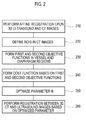
- FIG. 2 is a flowchart showing a non-rigid image registration procedure between the 3-dimensional ultrasound images and the CT images.
- the Iterative Closest Point (ICP)-based affine registration upon the 3-dimensional ultrasound images and the 3-dimensional CT images may be performed at block 210.
- ICP Iterative Closest Point
- the B-spline free form deformation may be adopted as a transformation in order to model a local deformation between the 3-dimensional ultrasound images and the 3-dimensional CT images.
- the transformation may be defined by displacements of control points having a uniform interval.
- the displacements may be represented with a transformation parameter ⁇ .
- the local deformation may be expected to be smooth over the liver so that the local deformation may be estimated by the smooth transformation.
- constraint C smooth may be defined and used as a 3-dimensional counterpart of 2-dimensional bending energy of a thin-plate of metal.
- the intensity relationships between vessels and a diaphragm in the ultrasound image and the CT image are quite different.
- the diaphragm may appear at a relatively high intensity due to the strong reflection of an ultrasound signal.
- This characteristic of the diaphragm in the ultrasound image may be associated with the diaphragm represented with a high gradient magnitude in the CT image.
- intensity values of a vessel region in the ultrasound image may be associated with those of the CT image, even though the contrast of the CT image is reversed.
- the objective function may be differently evaluated between the diaphragm and the vessel regions.
- the first objective function C diaphragm in the diaphragm region may be obtained by using the intensity values of the ultrasound image and the gradient magnitudes of the CT image
- the second objective function C vessel in the vessel region may be obtained by using intensity values of the ultrasound image and the CT image.
- a plurality of regions of interest may be defined in the CT image at block 220.
- the vessels and liver tissues in the CT image may be segmented by using the region-growing scheme. Thereafter, edge regions of segments may be expanded with a predetermined margin to thereby define the ROIs.
- the ROIs may be defined in the CT image, which provides relatively clearer boundaries of the vessels and the liver tissues than the ultrasound image.
- ROI masking may be carried out upon the vessel region and the diaphragm region in order to define the ROIs. This is to enable the CT image to be segmented into two regions, i.e., the vessel region and the diaphragm region through the ROI masking.
- an objective function C diaphragm in the diaphragm region and an objective function C vessel in the vessel region may be formed at block 230.
- the objective functions may be computed based on intensity values, gradient magnitudes and edge orientation angles in the ultrasound image and the CT image.
- the gradient magnitudes and the edge orientation angles may be computed as explained below.
- a structure matrix may be computed from each of the voxels constituting the ultrasound image and the CT image.
- Eigenvectors and eigenvalues may be extracted through an eigen-analysis of the structure matrix.
- the eigenvector with the largest eigenvalue may be defined as an edge orientation of the image, while the gradient magnitudes may be defined using the eigenvalue. If two images are perfectly registered onto each other, then the corresponding edge orientation angles may be identical to each other. Based on this relationship, an edge orientation coincidence function may be defined as a square of an inner product of two edge orientation vectors.
- the objective function C vessel may be determined based on mutual relationships between intensity values of the ultrasound image and the CT image in the vessel region.
- statistical entropy may be measured by using the intensity values of the ultrasound image, the intensity values of the CT image and the edge orientation coincidence function.
- the objective function C diafragm may be determined based on mutual relationships between the intensity values of the ultrasound image and the gradient magnitudes of the CT image in the diaphragm region.
- statistical entropy may be measured by using the intensity values of the ultrasound image, the gradient magnitudes of the CT image and the edge orientation coincidence function.
- a cost function may be defined with two objective functions C vessel and C diaphragm as following equation (1) at block 540.
- C C vessel + C diaphragm + ⁇ ⁇ C smooth wherein ⁇ is a weighting value representing tradeoff between alignment of two images and smoothness of the transformation C smooth .
- the transformation parameter ⁇ may be optimized at block 250.
- the gradient descent scheme may be utilized to find the optimized transformation parameter ⁇ .
- the transformation parameter ⁇ may be updated by using the gradient of the cost function as following equation (2).
- ⁇ k + 1 ⁇ k + ⁇ ⁇ ⁇ C wherein ⁇ denotes a block size and k is a natural number representing a repetition status of the gradient descent.
- ⁇ C may be approximated to a finite difference of the cost for implementation. If the following equation (3) is satisfied for a small positive value of ⁇ , then the optimization process may be terminated.
- a CT image may be transformed into an ultrasound image by using the optimized transform parameter ⁇ to thereby produce a registered CT image onto the ultrasound image at block 260.
- the system 100 may further include a display unit 140.
- the display unit 140 may display the 3-dimensional ultrasound images, 3-dimensional CT images, registered ultrasound-CT images and the like.
- the precise registration of the target object may be expected. Also, since the registration of the 3-dimensional CT image onto the 3-dimensional ultrasound image can be implemented regardless of local deformation, it may be useful for ultrasound guided intervention.
Landscapes
- Health & Medical Sciences (AREA)
- Life Sciences & Earth Sciences (AREA)
- Engineering & Computer Science (AREA)
- Physics & Mathematics (AREA)
- Medical Informatics (AREA)
- Biophysics (AREA)
- General Health & Medical Sciences (AREA)
- Veterinary Medicine (AREA)
- Pathology (AREA)
- Public Health (AREA)
- Biomedical Technology (AREA)
- Heart & Thoracic Surgery (AREA)
- Animal Behavior & Ethology (AREA)
- Molecular Biology (AREA)
- Surgery (AREA)
- Radiology & Medical Imaging (AREA)
- Nuclear Medicine, Radiotherapy & Molecular Imaging (AREA)
- Theoretical Computer Science (AREA)
- Computer Vision & Pattern Recognition (AREA)
- General Physics & Mathematics (AREA)
- High Energy & Nuclear Physics (AREA)
- Optics & Photonics (AREA)
- Pulmonology (AREA)
- Microelectronics & Electronic Packaging (AREA)
- Ultra Sonic Daignosis Equipment (AREA)
- Apparatus For Radiation Diagnosis (AREA)
Abstract
Description
- The present application claims priority from Korean Patent Application No.
10-2008-0053225 filed on June 5, 2008 - he present disclosure relates to image registrations, and more particularly to a non-rigid image registration between 3-dimensional computerized-tomography (CT) images and 3-dimensional ultrasound images based on the intensity and gradient information thereof.
- An ultrasound diagnostic system has been extensively used in the medical field due to its non-invasive and non-destructive nature. The ultrasound diagnostic system is highly safe and produces no dangerous side effects such as exposure to X-rays, etc. However, the ultrasound diagnostic system suffers from inherent shortcomings of an ultrasound image such as a low signal-to-noise ratio and a limited field of view. Thus, the image registration of a CT (or MR) image onto the ultrasound image has been introduced in order to compensate for deficiencies of the ultrasound image.
- The image guided intervention is one of the medical applications, which require the image registration between intraoperative and preoperative images. In case of the liver, a 3-dimensional ultrasound image is frequently used for the image-guided intervention. However, due to the poor quality of the 3-dimensional ultrasound image, it is required to display a preoperative 3-dimensional CT (or MR) image, which corresponds to an intraoperative 3-dimensional ultrasound image, but whose quality is relatively high compared thereto. In such a case, the image registration between the 3-dimensional ultrasound image and the 3-dimensional CT image is necessary. The 3-dimensional ultrasound image and the 3-dimensional CT image are formed at different respirations so that local deformation may appear. Thus, a non-rigid image registration, which is an essential step in various medical applications for image registration, should be performed.
- However, it is a difficult task to register the 3-dimensional CT image onto the 3-dimensional ultrasound image due to their different imaging characteristics. Several algorithms have been proposed for performing the non-rigid image registration between the 3-dimensional ultrasound and CT (or MR) liver images. For theses image registration, the 3-dimensional ultrasound and CT (or MR) images are converted into vessel probability images. Thereafter, a normalized cross correlation between two vessel probability images is maximized. Also, the image registration method between the 3-dimnsional ultrasound and CT (or MR) images, which is performed by extracting and registering centerlines of vessels, has been proposed. In such a method, however, the registration accuracy may depend on vessel segmentation accuracy in the 3-dimensional ultrasound and CT (or MR) images.
- An embodiment for a non-rigid image registration between 3-dimensional ultrasound and CT images is disclosed herein. In one embodiment, by way of non-limiting example, a system for non-rigid image registration between ultrasound images and computerized tomography (CT) images, comprises: an ultrasound image forming unit configured to transmit/receive ultrasound signals to/from a target object to thereby output electrical receive signals, and form 3-dimensional ultrasound images based on the electrical receive signals; a CT image forming unit configured to form 3-dimensional CT images of the target object; and a registration unit configured to determine first and second objective functions associated with first and second regions of the target object, respectively, based on the intensity and gradient information upon portions corresponding to the first and second regions in each of the 3-dimensional ultrasound and CT images, and perform non-rigid image registration between the 3-dimensional ultrasound images and the 3-dimensional CT images based on the first and second objective functions.
- The Summary is provided to introduce a selection of concepts in a simplified form that are further described below in the Detailed Description. This Summary is not intended to identify key or essential features of the claimed subject matter, nor is it intended to be used in determining the scope of the claimed subject matter.
-
- FIG. 1
- is a block diagram showing an illustrative embodiment of a system for a non-rigid registration between the 3-dimensional ultrasound images and the 3-dimensional CT images.
- FIG. 2
- is a flowchart showing a non-rigid image registration procedure between the 3-dimensional ultrasound images and the CT images.
- A detailed description may be provided with reference to the accompanying drawings. One of ordinary skill in the art may realize that the following description is illustrative only and is not in any way limiting. Other embodiments of the present invention may readily suggest themselves to such skilled persons having the benefit of this disclosure.
- In one embodiment, vessel and diaphragm information may be used for a non-rigid registration between computerized-tomography (CT) and ultrasound images of a target object. Although the CT image is referred to as an example of medical images registered onto the ultrasound images, the medical image is certainly not limited thereto. The medical images may also include a magnetic resonance imaging (MRI) image, positron emission tomography (PET) image and the like. In one embodiment, the target object may be a liver, although it is certainly not limited thereto. For robust and accurate registration, a new objective function based on a 3-dimensional joint histogram of intensity and gradient information, which is obtained from the ultrasound and CT images, may be adopted.
- In one embodiment, the non-rigid registration may be adopted to register affine-registered 3-dimensional ultrasound and CT images. Two features of the liver, i.e., features of vessels and a diaphragm, may be utilized for the registration. To find an accurate transformation for the non-rigid registration, a cost function may be defined by using objective functions of two features. In one embodiment, the cost may be minimized through an optimization process.
-
FIG. 1 is a block diagram showing an illustrative embodiment of a system for the non-rigid registration between the 3-dimensional ultrasound images and the CT images. - As depicted in
Fig. 1 , thesystem 100 may include an ultrasoundimage forming unit 110. The ultrasoundimage forming unit 110 may be configured to transmit/receive ultrasound signals to/from the target object to thereby output electrical receive signals. The ultrasoundimage forming unit 110 may be further configured to form ultrasound images of the target object based on the electrical receive signals. The ultrasound images may include a 3-dimensional ultrasound image obtained in a brightness mode (B-mode). - The
system 100 may further include a CTimage forming unit 120. The CT image forming unit may be configured to form 3-dimensional CT images of the target object. In one embodiment, each of the 3-dimensional ultrasound images and the 3-dimensional CT images may be obtained at different respirations. Thesystem 100 may further include aregistration unit 130 that may be operable to perform a non-rigid registration between the 3-dimensional ultrasound images and the 3-dimensional CT images based on the intensity and gradient information thereof. The operations of theregistration unit 130 will be described in detail with reference toFIG. 2 . -
FIG. 2 is a flowchart showing a non-rigid image registration procedure between the 3-dimensional ultrasound images and the CT images. Referring toFIG. 2 , the Iterative Closest Point (ICP)-based affine registration upon the 3-dimensional ultrasound images and the 3-dimensional CT images may be performed atblock 210. - In one embodiment, the B-spline free form deformation (FFD) may be adopted as a transformation in order to model a local deformation between the 3-dimensional ultrasound images and the 3-dimensional CT images. The transformation may be defined by displacements of control points having a uniform interval. The displacements may be represented with a transformation parameter Φ. In one embodiment, the local deformation may be expected to be smooth over the liver so that the local deformation may be estimated by the smooth transformation. Hence, constraint Csmooth may be defined and used as a 3-dimensional counterpart of 2-dimensional bending energy of a thin-plate of metal.
- The intensity relationships between vessels and a diaphragm in the ultrasound image and the CT image are quite different. In the ultrasound image, the diaphragm may appear at a relatively high intensity due to the strong reflection of an ultrasound signal. This characteristic of the diaphragm in the ultrasound image may be associated with the diaphragm represented with a high gradient magnitude in the CT image. Further, intensity values of a vessel region in the ultrasound image may be associated with those of the CT image, even though the contrast of the CT image is reversed. Thus, the objective function may be differently evaluated between the diaphragm and the vessel regions. While the first objective function Cdiaphragm in the diaphragm region may be obtained by using the intensity values of the ultrasound image and the gradient magnitudes of the CT image, the second objective function Cvessel in the vessel region may be obtained by using intensity values of the ultrasound image and the CT image.
- To evaluate the objective functions in the diaphragm and vessel regions, a plurality of regions of interest (ROIs) may be defined in the CT image at
block 220. The vessels and liver tissues in the CT image may be segmented by using the region-growing scheme. Thereafter, edge regions of segments may be expanded with a predetermined margin to thereby define the ROIs. In one embodiment, since computation necessary for the registration is carried out only upon overlapping portions of the ultrasound image and the CT image, it is sufficient to define the ROIs at one of the ultrasound image and the CT image. In one embodiment, the ROIs may be defined in the CT image, which provides relatively clearer boundaries of the vessels and the liver tissues than the ultrasound image. ROI masking may be carried out upon the vessel region and the diaphragm region in order to define the ROIs. This is to enable the CT image to be segmented into two regions, i.e., the vessel region and the diaphragm region through the ROI masking. - Subsequently, an objective function Cdiaphragm in the diaphragm region and an objective function Cvessel in the vessel region may be formed at
block 230. For robust and accurate registration, in one embodiment, the objective functions may be computed based on intensity values, gradient magnitudes and edge orientation angles in the ultrasound image and the CT image. - The gradient magnitudes and the edge orientation angles may be computed as explained below. First, a structure matrix may be computed from each of the voxels constituting the ultrasound image and the CT image. Eigenvectors and eigenvalues may be extracted through an eigen-analysis of the structure matrix. In such a case, the eigenvector with the largest eigenvalue may be defined as an edge orientation of the image, while the gradient magnitudes may be defined using the eigenvalue. If two images are perfectly registered onto each other, then the corresponding edge orientation angles may be identical to each other. Based on this relationship, an edge orientation coincidence function may be defined as a square of an inner product of two edge orientation vectors.
- The objective function Cvessel may be determined based on mutual relationships between intensity values of the ultrasound image and the CT image in the vessel region.
- To determine the objective function Cvessel, statistical entropy may be measured by using the intensity values of the ultrasound image, the intensity values of the CT image and the edge orientation coincidence function.
- Also, the objective function Cdiafragm may be determined based on mutual relationships between the intensity values of the ultrasound image and the gradient magnitudes of the CT image in the diaphragm region. To determine the objective function Cdiafragm, statistical entropy may be measured by using the intensity values of the ultrasound image, the gradient magnitudes of the CT image and the edge orientation coincidence function.
- Subsequently, a cost function may be defined with two objective functions Cvessel and Cdiaphragm as following equation (1) at block 540.

wherein λ is a weighting value representing tradeoff between alignment of two images and smoothness of the transformation Csmooth. The transformation parameter Φ may be optimized atblock 250. In one embodiment, the gradient descent scheme may be utilized to find the optimized transformation parameter Φ. The transformation parameter Φ may be updated by using the gradient of the cost function as following equation (2).
wherein µ denotes a block size and k is a natural number representing a repetition status of the gradient descent. ∇C may be approximated to a finite difference of the cost for implementation. If the following equation (3) is satisfied for a small positive value of ε, then the optimization process may be terminated.
- Finally, a CT image may be transformed into an ultrasound image by using the optimized transform parameter Φ to thereby produce a registered CT image onto the ultrasound image at
block 260. - The
system 100 may further include adisplay unit 140. Thedisplay unit 140 may display the 3-dimensional ultrasound images, 3-dimensional CT images, registered ultrasound-CT images and the like. - As mentioned above, as the objective function using the intensity and gradient information of the 3-dimensional ultrasound and CT images are adopted in one embodiment, the precise registration of the target object may be expected. Also, since the registration of the 3-dimensional CT image onto the 3-dimensional ultrasound image can be implemented regardless of local deformation, it may be useful for ultrasound guided intervention.
- Although embodiments have been described with reference to a number of illustrative embodiments thereof, it should be understood that numerous other modifications and embodiments can be devised by those skilled in the art that will fall within the spirit and scope of the principles of this disclosure. More particularly, numerous variations and modifications are possible in the component parts and/or arrangements of the subject combination arrangement within the scope of the disclosure, the drawings and the appended claims. In addition to variations and modifications in the component parts and/or arrangements, alternative uses will also be apparent to those skilled in the art.
Claims (9)
- A system for a non-rigid image registration between ultrasound images and computerized tomography (CT) images, comprising:an ultrasound image forming unit configured to transmit/receive ultrasound signals to/from a target object to thereby output electrical receive signals, the ultrasound image forming unit being further configured to form 3-dimensional ultrasound images based on the electrical receive signals;a CT image forming unit configured to form 3-dimensional CT images of the target object; anda registration unit configured to determine first and second objective functions associated with first and second regions of the target object, respectively, based on intensity and gradient information upon portions corresponding to the first and second regions in each of the 3-dimensional ultrasound and CT images, the registration unit being further configured to perform the non-rigid image registration between the 3-dimensional ultrasound images and the 3-dimensional CT images based on the first and second objective functions.
- The system of Claim 1, wherein the 3-dimensional ultrasound and CT images are 3-dimensional ultrasound and CT liver images, and wherein the first and second regions are diaphragm and vessel regions, respectively.
- The system of Claim 2, wherein the registration unit is configured to:perform an affine registration between the 3-dimensional ultrasound images and the 3-dimensional CT images;model a local deformation appearing at the affine-registered 3-dimensional ultrasound and CT images to define a transformation parameter;define a plurality of regions of interest (ROIs) in the 3-dimensional CT images;determine the first objective function in the diaphragm region and the second objective function in the vessel region within the ROIs, define a cost function based on the first and second objective functions;perform optimization for updating the transformation parameter based on the cost function; andform transformed CT images based on the optimized transformation parameter and perform non-rigid image registration upon the transformed CT images andthe ultrasound images.
- The system of Claim 3, wherein the affine registration is carried out based on Iterative Closest Point.
- The system of Claim 3, wherein the local deformation is modeled by imposing B-spline free form deformation on the affine-registered 3-dimensional ultrasound and CT images.
- The system of Claim 3, wherein the first objective function is formed by using intensity values of the 3-dimensional ultrasound images and gradient magnitudes of the 3-dimensional CT images, wherein the second objective function is formed by using intensity values of the 3-dimensional ultrasound and CT images, and wherein the first and second objective functions are formed based on a 3-dimensional joint histogram based on edges orientation angles.
- The system of Claim 6, wherein the ROIs are formed by segmenting vessels and tissues with a region-growing scheme and expanding edge regions of segments with a predetermined margin.
- The system of Claim 6, wherein the cost function is defined by using first and second objective functions Cdiaphragm and Cvessel as following equation.

wherein λ is a weighting value representing tradeoff between alignment of two images and smoothness of the transformation Csmooth. - The system of Claim 8, wherein the transformation parameter Φ is updated by repeatedly performing φ k+1 = φ k + µ· ∇C until |Ck - C k-1|< ε is satisfied, wherein µ denotes a block size, k is a natural number representing a repetition status of gradient descent and ε is a predetermined small positive value.
Applications Claiming Priority (1)
| Application Number | Priority Date | Filing Date | Title |
|---|---|---|---|
| KR20080053225 | 2008-06-05 |
Publications (2)
| Publication Number | Publication Date |
|---|---|
| EP2131212A2 true EP2131212A2 (en) | 2009-12-09 |
| EP2131212A3 EP2131212A3 (en) | 2011-10-05 |
Family
ID=41018010
Family Applications (1)
| Application Number | Title | Priority Date | Filing Date |
|---|---|---|---|
| EP09161545A Withdrawn EP2131212A3 (en) | 2008-06-05 | 2009-05-29 | Non-Rigid Registration Between CT Images and Ultrasound Images |
Country Status (4)
| Country | Link |
|---|---|
| US (1) | US8369597B2 (en) |
| EP (1) | EP2131212A3 (en) |
| JP (1) | JP4983860B2 (en) |
| KR (1) | KR101059312B1 (en) |
Cited By (3)
| Publication number | Priority date | Publication date | Assignee | Title |
|---|---|---|---|---|
| US9639938B2 (en) | 2012-10-26 | 2017-05-02 | Brainlab Ag | Matching patient images of different imaging modality using atlas information |
| CN111602173A (en) * | 2017-10-23 | 2020-08-28 | 布莱恩欧米克斯有限公司 | Tomographic data analysis |
| US20210196215A1 (en) * | 2018-05-18 | 2021-07-01 | The Johns Hopkins University | Multi-motion compensation for high-quality cone-beam ct of the head |
Families Citing this family (36)
| Publication number | Priority date | Publication date | Assignee | Title |
|---|---|---|---|---|
| KR100377835B1 (en) * | 2000-08-01 | 2003-03-31 | 박세환 | The way to manutacture textile printing screen by using oil paint |
| US7945117B2 (en) * | 2006-08-22 | 2011-05-17 | Siemens Medical Solutions Usa, Inc. | Methods and systems for registration of images |
| FR2914466B1 (en) * | 2007-04-02 | 2009-06-12 | Inst Nat Rech Inf Automat | IMAGE PROCESSING DEVICE FOR MATCHING IMAGES OF THE SAME PORTION OF A BODY OBTAINED BY MAGNETIC RESONANCE AND ULTRASOUND. |
| JP5580030B2 (en) * | 2009-12-16 | 2014-08-27 | 株式会社日立製作所 | Image processing apparatus and image alignment method |
| WO2012019162A1 (en) | 2010-08-06 | 2012-02-09 | Accuray, Inc. | Systems and methods for real-time tumor tracking during radiation treatment using ultrasound imaging |
| FR2966956B1 (en) * | 2010-10-27 | 2012-12-14 | Michelin Soc Tech | METHOD OF PRE-PROCESSING A DIMENSIONAL IMAGE OF THE SURFACE OF A TIRE USING SUCCESSIVE B-SPLINE DEFORMATIONS |
| BR112013009291A2 (en) * | 2010-10-27 | 2016-07-19 | Michelin & Cie | method of pretreatment of a three-dimensional image of the surface of a tire for use in inspecting said surface |
| KR101227272B1 (en) * | 2011-03-25 | 2013-01-28 | 가천대학교 산학협력단 | Image registration method of ultrasound imaging and magnetic resonance imaging |
| US9218643B2 (en) * | 2011-05-12 | 2015-12-22 | The Johns Hopkins University | Method and system for registering images |
| KR101842043B1 (en) | 2011-07-22 | 2018-03-26 | 삼성전자주식회사 | Apparatus and Method for analyzing ultrasound images |
| TWI446897B (en) | 2011-08-19 | 2014-08-01 | Ind Tech Res Inst | Ultrasound image registration apparatus and method thereof |
| US9092666B2 (en) | 2012-01-03 | 2015-07-28 | Samsung Electronics Co., Ltd. | Method and apparatus for estimating organ deformation model and medical image system |
| KR101768526B1 (en) | 2012-07-27 | 2017-08-17 | 삼성전자주식회사 | Method and apparatus for creating model of patient specified target organ based on blood vessel structure |
| KR101932721B1 (en) | 2012-09-07 | 2018-12-26 | 삼성전자주식회사 | Method and Appartus of maching medical images |
| KR102106535B1 (en) | 2013-02-06 | 2020-05-06 | 삼성전자주식회사 | Method, apparatus and system for generating model representing deformation of shape and location of organ in respiration cycle |
| JP5889265B2 (en) | 2013-04-22 | 2016-03-22 | ジーイー・メディカル・システムズ・グローバル・テクノロジー・カンパニー・エルエルシー | Image processing method, apparatus, and program |
| CN104116523B (en) * | 2013-04-25 | 2016-08-03 | 深圳迈瑞生物医疗电子股份有限公司 | A kind of ultrasonic image analyzes system and the method for analysis thereof |
| KR101527656B1 (en) * | 2013-12-12 | 2015-06-10 | 한국과학기술원 | Method and system for interpolating point spread function using nongrid image registration in medical image |
| KR102205898B1 (en) | 2013-09-04 | 2021-01-21 | 삼성전자주식회사 | Method and Apparatus for registering medical images |
| CN105593902A (en) * | 2013-09-30 | 2016-05-18 | 皇家飞利浦有限公司 | Method and system for automatic deformable registration |
| KR101578770B1 (en) | 2013-11-21 | 2015-12-18 | 삼성전자주식회사 | Apparatus por processing a medical image and method for processing a medical image |
| KR102233427B1 (en) * | 2014-04-14 | 2021-03-29 | 삼성전자주식회사 | Method and Apparatus for medical image registration |
| KR102294734B1 (en) * | 2014-09-30 | 2021-08-30 | 삼성전자주식회사 | Method and apparatus for image registration, and ultrasonic diagnosis apparatus |
| KR102328266B1 (en) * | 2014-10-29 | 2021-11-19 | 삼성전자주식회사 | Image processing apparatus and image processing method, and ultrasound apparatus |
| WO2016136065A1 (en) * | 2015-02-26 | 2016-09-01 | 株式会社日立製作所 | Ultrasonic image pickup device and image processing device |
| CA2980976C (en) | 2015-04-24 | 2023-03-21 | Sunnybrook Research Institute | Method for registering pre-operative images of a subject to an ultrasound treatment space |
| DE102015208929B3 (en) | 2015-05-13 | 2016-06-09 | Friedrich-Alexander-Universität Erlangen-Nürnberg | Method for 2D-3D registration, computing device and computer program |
| US10127655B2 (en) * | 2015-07-09 | 2018-11-13 | Samsung Medison Co., Ltd. | Medical imaging apparatus and method of operating same |
| CN107847216B (en) * | 2015-07-17 | 2024-01-23 | 皇家飞利浦有限公司 | Guidance of lung cancer radiation |
| EP3355790B1 (en) * | 2015-09-29 | 2023-05-10 | Institut National De La Sante Et De La Recherche Medicale (Inserm) | Method for determining a property of an object and associated device |
| KR101840106B1 (en) | 2016-02-04 | 2018-04-26 | 가톨릭대학교 산학협력단 | Method for analyzing blood flow using medical image |
| KR101900679B1 (en) | 2016-12-02 | 2018-09-20 | 숭실대학교산학협력단 | Method for 3d coronary registration based on vessel feature, recording medium and device for performing the method |
| CN110934613B (en) * | 2018-09-21 | 2023-01-13 | 佳能医疗系统株式会社 | Ultrasonic diagnostic apparatus and ultrasonic diagnostic method |
| CN109934861B (en) * | 2019-01-22 | 2022-10-18 | 广东工业大学 | Head and neck multi-modal medical image automatic registration method |
| KR102375910B1 (en) * | 2020-03-02 | 2022-03-16 | 연세대학교 산학협력단 | Ultrasound Image-guided Method and Apparatus |
| CN112184781A (en) * | 2020-09-14 | 2021-01-05 | 中国科学院深圳先进技术研究院 | Method, device and equipment for registering ultrasonic image and CT image |
Family Cites Families (13)
| Publication number | Priority date | Publication date | Assignee | Title |
|---|---|---|---|---|
| US7058205B2 (en) * | 2001-12-07 | 2006-06-06 | Xerox Corporation | Robust, on-line, view-based appearance models for visual motion analysis and visual tracking |
| JP4406226B2 (en) | 2003-07-02 | 2010-01-27 | 株式会社東芝 | Biological information video device |
| JP4317412B2 (en) * | 2003-09-29 | 2009-08-19 | 株式会社日立製作所 | Image processing method |
| US8090429B2 (en) * | 2004-06-30 | 2012-01-03 | Siemens Medical Solutions Usa, Inc. | Systems and methods for localized image registration and fusion |
| US20070167784A1 (en) * | 2005-12-13 | 2007-07-19 | Raj Shekhar | Real-time Elastic Registration to Determine Temporal Evolution of Internal Tissues for Image-Guided Interventions |
| KR20070110965A (en) | 2006-05-16 | 2007-11-21 | 주식회사 메디슨 | Ultrasound system for displaying compound image of ultrasound image and external medical image |
| JP2008086400A (en) * | 2006-09-29 | 2008-04-17 | Gifu Univ | Mammographic image diagnostic system |
| EP2081494B1 (en) * | 2006-11-16 | 2018-07-11 | Vanderbilt University | System and method of compensating for organ deformation |
| US8098911B2 (en) * | 2006-12-05 | 2012-01-17 | Siemens Aktiengesellschaft | Method and system for registration of contrast-enhanced images with volume-preserving constraint |
| KR20080053057A (en) | 2006-12-08 | 2008-06-12 | 주식회사 메디슨 | Ultrasound imaging system and method for forming and displaying fusion image of ultrasound image and external medical image |
| JP5335280B2 (en) * | 2008-05-13 | 2013-11-06 | キヤノン株式会社 | Alignment processing apparatus, alignment method, program, and storage medium |
| US8111892B2 (en) * | 2008-06-04 | 2012-02-07 | Medison Co., Ltd. | Registration of CT image onto ultrasound images |
| JP5508401B2 (en) * | 2008-06-05 | 2014-05-28 | コーニンクレッカ フィリップス エヌ ヴェ | Ultrasound imaging of extended field of view by guided EFOV scanning |
-
2009
- 2009-05-29 EP EP09161545A patent/EP2131212A3/en not_active Withdrawn
- 2009-06-02 US US12/477,081 patent/US8369597B2/en active Active
- 2009-06-05 JP JP2009136230A patent/JP4983860B2/en not_active Expired - Fee Related
- 2009-06-05 KR KR1020090050039A patent/KR101059312B1/en active IP Right Grant
Non-Patent Citations (2)
| Title |
|---|
| D LEE: "Non-rigid registration of 3D ultrasound and CT images in the liver using intensity and gradient information", INT J CARS, 1 June 2008 (2008-06-01), pages S38 - S39, XP055180134, Retrieved from the Internet <URL:http://issserver.kaist.ac.kr/Papers/IC/ic119.pdf> [retrieved on 20150330] * |
| W.H. NAM, ANATOMICAL FEATURE EXTRACTION IN 3D B-MODE ULTRASOUND LIVER IMAGES FOR CT-ULTRASOUND IMAGE REGISTRATION |
Cited By (8)
| Publication number | Priority date | Publication date | Assignee | Title |
|---|---|---|---|---|
| US9639938B2 (en) | 2012-10-26 | 2017-05-02 | Brainlab Ag | Matching patient images of different imaging modality using atlas information |
| US10262418B2 (en) | 2012-10-26 | 2019-04-16 | Brainlab Ag | Matching patient images and images of an anatomical atlas |
| US10388013B2 (en) | 2012-10-26 | 2019-08-20 | Brainlab Ag | Matching patient images and images of an anatomical atlas |
| US10402971B2 (en) | 2012-10-26 | 2019-09-03 | Brainlab Ag | Matching patient images and images of an anatomical atlas |
| US10417762B2 (en) | 2012-10-26 | 2019-09-17 | Brainlab Ag | Matching patient images and images of an anatomical atlas |
| CN111602173A (en) * | 2017-10-23 | 2020-08-28 | 布莱恩欧米克斯有限公司 | Tomographic data analysis |
| US10902596B2 (en) | 2017-10-23 | 2021-01-26 | Brainomix Limited | Tomographic data analysis |
| US20210196215A1 (en) * | 2018-05-18 | 2021-07-01 | The Johns Hopkins University | Multi-motion compensation for high-quality cone-beam ct of the head |
Also Published As
| Publication number | Publication date |
|---|---|
| KR101059312B1 (en) | 2011-08-24 |
| KR20090127101A (en) | 2009-12-09 |
| JP2009291617A (en) | 2009-12-17 |
| EP2131212A3 (en) | 2011-10-05 |
| US20090304252A1 (en) | 2009-12-10 |
| US8369597B2 (en) | 2013-02-05 |
| JP4983860B2 (en) | 2012-07-25 |
Similar Documents
| Publication | Publication Date | Title |
|---|---|---|
| US8369597B2 (en) | Non-rigid registration between CT images and ultrasound images | |
| Rajinikanth et al. | An approach to examine magnetic resonance angiography based on Tsallis entropy and deformable snake model | |
| Martin et al. | Automated segmentation of the prostate in 3D MR images using a probabilistic atlas and a spatially constrained deformable model | |
| EP1779289B1 (en) | Diagnostic system for multimodality mammography | |
| Rundo et al. | Automated prostate gland segmentation based on an unsupervised fuzzy C-means clustering technique using multispectral T1w and T2w MR imaging | |
| US11013495B2 (en) | Method and apparatus for registering medical images | |
| US20120170823A1 (en) | System and method for image based multiple-modality cardiac image alignment | |
| Gubern-Mérida et al. | Segmentation of the pectoral muscle in breast MRI using atlas-based approaches | |
| Wirth et al. | Nonrigid mammogram registration using mutual information | |
| Alba et al. | Automatic cardiac LV segmentation in MRI using modified graph cuts with smoothness and interslice constraints | |
| Wismüller et al. | Segmentation and classification of dynamic breast magnetic resonance image data | |
| Qin et al. | Automatic segmentation of right ventricular ultrasound images using sparse matrix transform and a level set | |
| Leung et al. | Left ventricular border tracking using cardiac motion models and optical flow | |
| WO2013094166A1 (en) | Image processing device, image processing method, and image processing program | |
| Gupta et al. | Fully automatic registration and segmentation of first-pass myocardial perfusion MR image sequences | |
| US8483464B2 (en) | System and method for detecting and correcting registration misalignment of MR perfusion images | |
| Lorenz et al. | Automated abdominal plane and circumference estimation in 3D US for fetal screening | |
| KR20120000729A (en) | Position tracking method for vascular treatment micro robot through registration between x ray image and ct 3d model | |
| EP2710553B1 (en) | Determination of a physically-varying anatomical structure | |
| Chen et al. | Medical image segmentation based on the Bayesian level set method | |
| KR20120000722A (en) | Non rigid fusion method for multi medicla modality | |
| Morais et al. | Fully automatic left ventricular myocardial strain estimation in 2D short-axis tagged magnetic resonance imaging | |
| Chandrashekara et al. | Analysis of myocardial motion and strain patterns using a cylindrical B-spline transformation model | |
| Dormer et al. | Determining cardiac fiber orientation using FSL and registered ultrasound/DTI volumes | |
| Chandler et al. | Slice-to-volume registration using mutual information between probabilistic image classifications |
Legal Events
| Date | Code | Title | Description |
|---|---|---|---|
| PUAI | Public reference made under article 153(3) epc to a published international application that has entered the european phase |
Free format text: ORIGINAL CODE: 0009012 |
|
| AK | Designated contracting states |
Kind code of ref document: A2 Designated state(s): AT BE BG CH CY CZ DE DK EE ES FI FR GB GR HR HU IE IS IT LI LT LU LV MC MK MT NL NO PL PT RO SE SI SK TR |
|
| PUAL | Search report despatched |
Free format text: ORIGINAL CODE: 0009013 |
|
| AK | Designated contracting states |
Kind code of ref document: A3 Designated state(s): AT BE BG CH CY CZ DE DK EE ES FI FR GB GR HR HU IE IS IT LI LT LU LV MC MK MT NL NO PL PT RO SE SI SK TR |
|
| RIC1 | Information provided on ipc code assigned before grant |
Ipc: A61B 6/03 20060101ALI20110830BHEP Ipc: G01S 15/89 20060101AFI20110830BHEP |
|
| 17P | Request for examination filed |
Effective date: 20120403 |
|
| 17Q | First examination report despatched |
Effective date: 20120604 |
|
| STAA | Information on the status of an ep patent application or granted ep patent |
Free format text: STATUS: THE APPLICATION IS DEEMED TO BE WITHDRAWN |
|
| 18D | Application deemed to be withdrawn |
Effective date: 20151021 |