EP2120821B1 - Loading a device for a pulmonary implant - Google Patents
Loading a device for a pulmonary implant Download PDFInfo
- Publication number
- EP2120821B1 EP2120821B1 EP08743733.1A EP08743733A EP2120821B1 EP 2120821 B1 EP2120821 B1 EP 2120821B1 EP 08743733 A EP08743733 A EP 08743733A EP 2120821 B1 EP2120821 B1 EP 2120821B1
- Authority
- EP
- European Patent Office
- Prior art keywords
- implant
- catheter
- tubular structure
- collapsible
- loading
- Prior art date
- Legal status (The legal status is an assumption and is not a legal conclusion. Google has not performed a legal analysis and makes no representation as to the accuracy of the status listed.)
- Active
Links
- 239000007943 implant Substances 0.000 title claims description 143
- 238000011068 loading method Methods 0.000 title claims description 70
- 230000002685 pulmonary effect Effects 0.000 title claims description 22
- 230000006835 compression Effects 0.000 claims description 19
- 238000007906 compression Methods 0.000 claims description 19
- 230000007246 mechanism Effects 0.000 claims description 7
- 230000001419 dependent effect Effects 0.000 claims description 3
- 239000012781 shape memory material Substances 0.000 claims description 3
- 238000004806 packaging method and process Methods 0.000 claims description 2
- 239000012780 transparent material Substances 0.000 claims description 2
- 210000003811 finger Anatomy 0.000 description 5
- 238000003780 insertion Methods 0.000 description 5
- 230000037431 insertion Effects 0.000 description 5
- 230000008901 benefit Effects 0.000 description 3
- HLXZNVUGXRDIFK-UHFFFAOYSA-N nickel titanium Chemical compound [Ti].[Ti].[Ti].[Ti].[Ti].[Ti].[Ti].[Ti].[Ti].[Ti].[Ti].[Ni].[Ni].[Ni].[Ni].[Ni].[Ni].[Ni].[Ni].[Ni].[Ni].[Ni].[Ni].[Ni].[Ni] HLXZNVUGXRDIFK-UHFFFAOYSA-N 0.000 description 3
- 229910001000 nickel titanium Inorganic materials 0.000 description 3
- 238000002513 implantation Methods 0.000 description 2
- 239000000463 material Substances 0.000 description 2
- 238000012986 modification Methods 0.000 description 2
- 230000004048 modification Effects 0.000 description 2
- 230000037361 pathway Effects 0.000 description 2
- 206010003598 Atelectasis Diseases 0.000 description 1
- 208000019693 Lung disease Diseases 0.000 description 1
- 208000007123 Pulmonary Atelectasis Diseases 0.000 description 1
- 230000015556 catabolic process Effects 0.000 description 1
- 238000006731 degradation reaction Methods 0.000 description 1
- 239000012530 fluid Substances 0.000 description 1
- 239000011521 glass Substances 0.000 description 1
- 238000007373 indentation Methods 0.000 description 1
- 230000001939 inductive effect Effects 0.000 description 1
- 239000003562 lightweight material Substances 0.000 description 1
- 238000000034 method Methods 0.000 description 1
- 238000002360 preparation method Methods 0.000 description 1
- 230000001681 protective effect Effects 0.000 description 1
- 230000000284 resting effect Effects 0.000 description 1
- 239000007787 solid Substances 0.000 description 1
- 230000000087 stabilizing effect Effects 0.000 description 1
- 210000003813 thumb Anatomy 0.000 description 1
- 210000003437 trachea Anatomy 0.000 description 1
- 230000032258 transport Effects 0.000 description 1
- 230000002485 urinary effect Effects 0.000 description 1
- 230000002792 vascular Effects 0.000 description 1
Images


Classifications
-
- A—HUMAN NECESSITIES
- A61—MEDICAL OR VETERINARY SCIENCE; HYGIENE
- A61B—DIAGNOSIS; SURGERY; IDENTIFICATION
- A61B17/00—Surgical instruments, devices or methods, e.g. tourniquets
- A61B17/12—Surgical instruments, devices or methods, e.g. tourniquets for ligaturing or otherwise compressing tubular parts of the body, e.g. blood vessels, umbilical cord
- A61B17/12022—Occluding by internal devices, e.g. balloons or releasable wires
- A61B17/12099—Occluding by internal devices, e.g. balloons or releasable wires characterised by the location of the occluder
- A61B17/12104—Occluding by internal devices, e.g. balloons or releasable wires characterised by the location of the occluder in an air passage
-
- A—HUMAN NECESSITIES
- A61—MEDICAL OR VETERINARY SCIENCE; HYGIENE
- A61B—DIAGNOSIS; SURGERY; IDENTIFICATION
- A61B17/00—Surgical instruments, devices or methods, e.g. tourniquets
- A61B17/12—Surgical instruments, devices or methods, e.g. tourniquets for ligaturing or otherwise compressing tubular parts of the body, e.g. blood vessels, umbilical cord
- A61B17/12022—Occluding by internal devices, e.g. balloons or releasable wires
- A61B17/12131—Occluding by internal devices, e.g. balloons or releasable wires characterised by the type of occluding device
- A61B17/12168—Occluding by internal devices, e.g. balloons or releasable wires characterised by the type of occluding device having a mesh structure
- A61B17/12172—Occluding by internal devices, e.g. balloons or releasable wires characterised by the type of occluding device having a mesh structure having a pre-set deployed three-dimensional shape
-
- A—HUMAN NECESSITIES
- A61—MEDICAL OR VETERINARY SCIENCE; HYGIENE
- A61F—FILTERS IMPLANTABLE INTO BLOOD VESSELS; PROSTHESES; DEVICES PROVIDING PATENCY TO, OR PREVENTING COLLAPSING OF, TUBULAR STRUCTURES OF THE BODY, e.g. STENTS; ORTHOPAEDIC, NURSING OR CONTRACEPTIVE DEVICES; FOMENTATION; TREATMENT OR PROTECTION OF EYES OR EARS; BANDAGES, DRESSINGS OR ABSORBENT PADS; FIRST-AID KITS
- A61F2/00—Filters implantable into blood vessels; Prostheses, i.e. artificial substitutes or replacements for parts of the body; Appliances for connecting them with the body; Devices providing patency to, or preventing collapsing of, tubular structures of the body, e.g. stents
- A61F2/95—Instruments specially adapted for placement or removal of stents or stent-grafts
- A61F2/9522—Means for mounting a stent or stent-graft onto or into a placement instrument
- A61F2/9525—Means for mounting a stent or stent-graft onto or into a placement instrument using a funnel
-
- A—HUMAN NECESSITIES
- A61—MEDICAL OR VETERINARY SCIENCE; HYGIENE
- A61B—DIAGNOSIS; SURGERY; IDENTIFICATION
- A61B17/00—Surgical instruments, devices or methods, e.g. tourniquets
- A61B2017/00526—Methods of manufacturing
- A61B2017/0053—Loading magazines or sutures into applying tools
-
- A—HUMAN NECESSITIES
- A61—MEDICAL OR VETERINARY SCIENCE; HYGIENE
- A61B—DIAGNOSIS; SURGERY; IDENTIFICATION
- A61B17/00—Surgical instruments, devices or methods, e.g. tourniquets
- A61B2017/00743—Type of operation; Specification of treatment sites
- A61B2017/00809—Lung operations
-
- A—HUMAN NECESSITIES
- A61—MEDICAL OR VETERINARY SCIENCE; HYGIENE
- A61B—DIAGNOSIS; SURGERY; IDENTIFICATION
- A61B17/00—Surgical instruments, devices or methods, e.g. tourniquets
- A61B2017/00831—Material properties
- A61B2017/00867—Material properties shape memory effect
-
- A—HUMAN NECESSITIES
- A61—MEDICAL OR VETERINARY SCIENCE; HYGIENE
- A61B—DIAGNOSIS; SURGERY; IDENTIFICATION
- A61B17/00—Surgical instruments, devices or methods, e.g. tourniquets
- A61B17/12—Surgical instruments, devices or methods, e.g. tourniquets for ligaturing or otherwise compressing tubular parts of the body, e.g. blood vessels, umbilical cord
- A61B17/12022—Occluding by internal devices, e.g. balloons or releasable wires
- A61B2017/1205—Introduction devices
- A61B2017/12054—Details concerning the detachment of the occluding device from the introduction device
-
- A—HUMAN NECESSITIES
- A61—MEDICAL OR VETERINARY SCIENCE; HYGIENE
- A61B—DIAGNOSIS; SURGERY; IDENTIFICATION
- A61B50/00—Containers, covers, furniture or holders specially adapted for surgical or diagnostic appliances or instruments, e.g. sterile covers
- A61B50/30—Containers specially adapted for packaging, protecting, dispensing, collecting or disposing of surgical or diagnostic appliances or instruments
-
- A—HUMAN NECESSITIES
- A61—MEDICAL OR VETERINARY SCIENCE; HYGIENE
- A61F—FILTERS IMPLANTABLE INTO BLOOD VESSELS; PROSTHESES; DEVICES PROVIDING PATENCY TO, OR PREVENTING COLLAPSING OF, TUBULAR STRUCTURES OF THE BODY, e.g. STENTS; ORTHOPAEDIC, NURSING OR CONTRACEPTIVE DEVICES; FOMENTATION; TREATMENT OR PROTECTION OF EYES OR EARS; BANDAGES, DRESSINGS OR ABSORBENT PADS; FIRST-AID KITS
- A61F2/00—Filters implantable into blood vessels; Prostheses, i.e. artificial substitutes or replacements for parts of the body; Appliances for connecting them with the body; Devices providing patency to, or preventing collapsing of, tubular structures of the body, e.g. stents
- A61F2/02—Prostheses implantable into the body
- A61F2/04—Hollow or tubular parts of organs, e.g. bladders, tracheae, bronchi or bile ducts
-
- A—HUMAN NECESSITIES
- A61—MEDICAL OR VETERINARY SCIENCE; HYGIENE
- A61F—FILTERS IMPLANTABLE INTO BLOOD VESSELS; PROSTHESES; DEVICES PROVIDING PATENCY TO, OR PREVENTING COLLAPSING OF, TUBULAR STRUCTURES OF THE BODY, e.g. STENTS; ORTHOPAEDIC, NURSING OR CONTRACEPTIVE DEVICES; FOMENTATION; TREATMENT OR PROTECTION OF EYES OR EARS; BANDAGES, DRESSINGS OR ABSORBENT PADS; FIRST-AID KITS
- A61F2/00—Filters implantable into blood vessels; Prostheses, i.e. artificial substitutes or replacements for parts of the body; Appliances for connecting them with the body; Devices providing patency to, or preventing collapsing of, tubular structures of the body, e.g. stents
- A61F2/02—Prostheses implantable into the body
- A61F2/24—Heart valves ; Vascular valves, e.g. venous valves; Heart implants, e.g. passive devices for improving the function of the native valve or the heart muscle; Transmyocardial revascularisation [TMR] devices; Valves implantable in the body
- A61F2/2427—Devices for manipulating or deploying heart valves during implantation
- A61F2/2436—Deployment by retracting a sheath
-
- A—HUMAN NECESSITIES
- A61—MEDICAL OR VETERINARY SCIENCE; HYGIENE
- A61F—FILTERS IMPLANTABLE INTO BLOOD VESSELS; PROSTHESES; DEVICES PROVIDING PATENCY TO, OR PREVENTING COLLAPSING OF, TUBULAR STRUCTURES OF THE BODY, e.g. STENTS; ORTHOPAEDIC, NURSING OR CONTRACEPTIVE DEVICES; FOMENTATION; TREATMENT OR PROTECTION OF EYES OR EARS; BANDAGES, DRESSINGS OR ABSORBENT PADS; FIRST-AID KITS
- A61F2/00—Filters implantable into blood vessels; Prostheses, i.e. artificial substitutes or replacements for parts of the body; Appliances for connecting them with the body; Devices providing patency to, or preventing collapsing of, tubular structures of the body, e.g. stents
- A61F2/95—Instruments specially adapted for placement or removal of stents or stent-grafts
- A61F2/9522—Means for mounting a stent or stent-graft onto or into a placement instrument
-
- A—HUMAN NECESSITIES
- A61—MEDICAL OR VETERINARY SCIENCE; HYGIENE
- A61F—FILTERS IMPLANTABLE INTO BLOOD VESSELS; PROSTHESES; DEVICES PROVIDING PATENCY TO, OR PREVENTING COLLAPSING OF, TUBULAR STRUCTURES OF THE BODY, e.g. STENTS; ORTHOPAEDIC, NURSING OR CONTRACEPTIVE DEVICES; FOMENTATION; TREATMENT OR PROTECTION OF EYES OR EARS; BANDAGES, DRESSINGS OR ABSORBENT PADS; FIRST-AID KITS
- A61F2/00—Filters implantable into blood vessels; Prostheses, i.e. artificial substitutes or replacements for parts of the body; Appliances for connecting them with the body; Devices providing patency to, or preventing collapsing of, tubular structures of the body, e.g. stents
- A61F2/02—Prostheses implantable into the body
- A61F2/04—Hollow or tubular parts of organs, e.g. bladders, tracheae, bronchi or bile ducts
- A61F2002/043—Bronchi
Definitions
- This invention relates generally to implants, and specifically to devices for loading a collapsible implant onto a delivery catheter, and more particularly for loading a collapsible pulmonary implant onto a delivery catheter.
- Collapsible self-expanding implants are well known in the medical device field. Historical medical uses for such implants include maintaining openings in vascular, urinary, biliary, esophageal, and renal tracts, and vena cava filters. Recently, modified pulmonary implants are being contemplated for the treatment of pulmonary disorders. Some such pulmonary devices differ from conventional occlusive devices in that they are designed to constrict, block, or significantly restrict fluid flow in a pulmonary passageway, rather than maintain an opening in it.
- Self-expanding pulmonary implants must be compressed to enable delivery through relatively small and curved body pathways.
- a delivery device such as a delivery catheter, retains the pulmonary implant in its radially compressed state as it transports the implant to a treatment site through relevant bodily passageways. There, the implant is released and expands to its non-compressed shape.
- implants that are already pre-loaded onto a catheter might lose some of their functionality as they remain on the shelf for extended periods of time before they are used in a patient.
- the device would be maintained in its native state until it is ready to be used in a patient.
- the physician should be able to load the implant onto the delivery catheter using a simple maneuver.
- the implant should be well protected during shipping and transfer until it is ready to be used. A simple system that would meet all the above needs would be highly desirable.
- U.S. patent No. 6,096,027 discloses an apparatus for loading a stent onto a catheter using a flexible sleeve to encase the stent as it is pulled through a tapered passageway.
- Commonly assigned published U.S. patent application No. 20060162731A1 discloses a loading mandrel positioned within a loading body, wherein the loading mandrel is manipulated to load an occlusal stent into a wide-mouthed end of the loading body and move the occlusal stent to a narrow-mouthed end within the loading body.
- US 6,068,635 relates to a procedure as well as a device for introducing an endoprosthesis into the distal end of a catheter by means of which the endoprosthesis is introduced into a vessel for implantation therein and is released to undergo self expansion by moving the tip of a catheter axially relative to the distal end of an outer catheter.
- An embodiment of the device comprises a hollow cylindrical housing designed to receive the endoprosthesis, a piston axially displaceable therein which can be brought into engagement with the endoprosthesis, and a nose section arranged at one end of the housing, said nose section being provided with a recess tapering in the direction of an opening, and by means of said recess the endoprosthesis supplied by the piston may be introduced, with compressed diameter and in elongated form, into the distal end of the catheter replaceably arranged on the nose section.
- US 2004/0210248 describes an assembly which delivers an intra-bronchial device into an air passageway.
- the assembly includes a delivery catheter having a deployment lumen with a distal end arranged to receive the intra-bronchial device in a delivery configuration, and arranged to be passed down a trachea and advanced to a location for deployment of the intra-bronchial device, and to deploy the intra-bronchial device by retracting the deployment catheter.
- the assembly further includes a bronchial device supply tool associated with the distal end, and arranged to carry the intra-bronchial device in a storage configuration and to load the intra-bronchial device in a delivery configuration into the deployment lumen of distal end, and the intra-bronchial device carried in the supply tool in a storage configuration.
- An example of the supply tool includes a storage portion, a delivery portion, and a configuration-changing portion coupled between the storage portion and the delivery portion.
- the device for loading a collapsible implant according to the invention is defined in claim 1.
- Preferred embodiments are defined in the dependent claims.
- a loading device accepts a flexible and self-expanding implant, as well as the distal end of a delivery catheter.
- the loading device guides the implant through a narrowing passage that feeds into the distal end of the catheter. As the implant passes through the narrowing passage, it is compressed to a diameter that allows the implant to be inserted into the catheter.
- a loading device comprises an outer tubular structure and an inner tubular structure.
- the outer tubular structure comprises a narrowing passage configured to receive a catheter at one end and a collapsible implant at another end.
- the inner tubular structure is configured to move slidably and co-axially within the outer tubular structure.
- the inner tubular structure comprises a carrier pin configured to move within the narrowing passage as the inner tubular structure slides into the outer tubular structure. The sliding of the inner tubular structure into the outer tubular structure causes an implant mounted on the carrier pin to collapse as the implant moves through the narrowing passage and into the distal end of a catheter.
- the outer tubular structure further comprises a grasper to stabilize the catheter for receipt of the collapsible implant, and the internal diameter of the inner tubular structure varies to cause the grasper to first contract and stabilize the catheter, and then expand and release the catheter, as the grasper moves into the inner tubular structure.
- the loading device comprises an outer shaft comprising a narrowing passage leading to an opening for receiving the distal end of a catheter, an opening for accepting a collapsible implant, and two compression members.
- the first compression member is configured to move slidably within the outer shaft and guides the implant through the narrowing passage, thereby collapsing it.
- the second compression member then inserts the implant into the catheter.
- the loading device comprises two tubular structures with opposing narrowing inner diameters, with one tubular structure configured to move slidably over the other. Placement of an implant between the structures, followed by sliding one tubular structure over the other, causes the implant to radially compress within the two opposing narrowing cavities.
- a catheter with a slotted rod is configured to hold and pull a collapsible implant through a narrowing passage and into the distal opening of the catheter.
- the slotted rod comprises a spring loaded ball configured to increase the grip on the implant.
- the rod comprises a grasping or latching mechanism configured to latch onto the implant as the implant is pulled through the narrowing passage and into the catheter.
- the rod comprises a loop wire configured to secure the implant as the implant is pulled through the narrowing passage and into the catheter.
- the loop wire may comprise shape-memory material such as Nitinol to allow it to release the implant by increasing the slack in the loop wire.
- kits for distributing and storing the system components according to claim 15.
- the kits will include packaging for holding the components, usually including a primary package which may be a box, pouch, cylinder, or other protective package.
- the individual system components are usually held within separate sterile containers within the primary package, usually being in pouches, cylinders, or the like.
- self-expanding implants may be preloaded within the loading device and held in their uncollapsed configuration, thus reducing the risk of damaging the elastic implant materials prior to loading and implantation.
- the kits may comprise instructions for use setting forth any of the loading methods described herein.
- a loading device for loading a collapsible pulmonary implant onto a delivery system, in preparation for delivering the implant into the pulmonary airways of a patient.
- the delivery system may comprise a catheter.
- Collapsible pulmonary implants are made of memory-shape materials, such as Nitinol, and are compressed to enable delivery through relatively small and curved bodily pathways to the treatment site.
- Delivery devices such as catheters, retain the collapsed pulmonary implants in a radially compressed state for delivery to the treatment site, where the implant is released into the airway and regains its non-compressed shape.
- the present description discloses various embodiments of a loading device that collapses such implants and optionally inserts them onto a delivery catheter.
- the present description further discloses various embodiments of catheters comprising rods for securing and pulling a collapsible pulmonary implant through a narrowing passage and into the catheter, collapsing the implant before it enters the catheter.
- the present embodiments can be used with any implants that are delivered bronchoscopically for inducing atelectasis. Such implants may be restrictive or occlusive in nature, or valve-based.
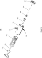
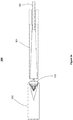
- FIGS 1a-1g illustrate a loading device 100 according to a preferred embodiment of the present invention.
- Figure 1a shows the assembled loading device 100.
- An inner tubular structure 102 is configured to move slidably into and out of an outer tubular structure 101.
- the inner tubular structure 102 is hereinafter also referred to as a plunger 102
- the outer tubular structure 101 is hereinafter also referred to as a barrel 101.
- the plunger 102 comprises an optional cap 107.
- a carrier pin 104 may be attached to the plunger 102 itself, or alternatively attached to the cap 107 as is shown in the Figures.
- a collapsible pulmonary implant 103 is mounted on the carrier pin 104, positioned for compression through a narrowing passage and insertion into a catheter.
- One end of the barrel 101 is configured to receive the implant 103 mounted on the carrier pin 104, and the other end is configured to receive a catheter (as is shown in the additional figures below).
- the carrier pin 104 guides the implant 103 through the narrowing passage 106, compressing the implant 103 and inserting it into the opening at the distal end of the catheter.
- the barrel 101 comprises optional finger rests 110.
- Finger rests 110 and cap 107 allow a user to place two fingers in the finger rests 110 and hold the loading device 100 while using the thumb or the palm of the hand to slide the plunger 102 into the barrel 101, similar to using a syringe or a pump, as shown in Figure 1e .
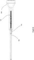
- Figure 1b shows an exploded view of the components of the loading device 100, showing the barrel 101 with optional finger rests 110, the plunger 102, a cap 107, a carrier pin 104, a narrowing passage 106, a catheter passage 109, an optional grasper 108, and a collapsible implant 103.
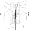
- Figures 1c and 1d show interior and cross-sectional views of the loading device 100, with a catheter 105 inserted into the loading device 100.
- the loading device 100 comprises a narrowing passage 106. Movement of the implant 103 into the narrowing passage 106 compresses the implant 103, thereby reducing its diameter until the diameter is small enough to fit into the catheter 105. A continuation of the same plunging motion that compresses the implant 103 also inserts it into the catheter 105.
- the catheter 105 comes to rest as it comes in contact with indentations 112. A user compresses the loading device, as shown in Figure 1e , thereby causing tubular structure 102 to move into tubular structure 101.
- the loading device 100 optionally comprises a grasper 108.
- the grasper 108 is configured to grasp down on an inserted catheter 105 upon application of a force, which is provided by the tapered cavity of the plunger 102.
- This cavity comprises a first section with a reduced internal diameter 111a and a second section with a larger internal diameter 111b, as depicted in Figure 1d .
- the grasper 108 Prior to the plunger 102 sliding into the barrel 101, the grasper 108 is in an open, released state. The sliding of the plunger 102 into the barrel 101 forces the grasper 108 through the reduced diameter section of the plunger 102 and causes the grasper 108 arms to close. As a result, the grasper 108 grasps and holds down the catheter 105, thereby stabilizing the catheter 105 for the insertion of the compressed implant 103 during the movement of the loading device 100. Upon moving through and exiting the reduced diameter section of the plunger 102 and entering the larger diameter section, the grasper 108 arms return to their open state, thereby releasing the loaded catheter 105 and allowing a user to remove the catheter 105 from the loading device 100.
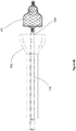
- Figure 1f shows the loading device 100 in a partially compressed state.
- the plunger 102 has moved into the tubular structure 101, and the carrier pin 104 has guided the implant 103 through the narrowing passage 106 and compressed it.
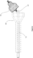
- Figure 1g shows the loading device 100 in a fully compressed state.
- the loading device 100 is fully compressed, i.e., the plunger 102 has completed its travel from the proximal end of the barrel 101 to the distal end of the barrel 101, the implant 103 has been inserted into the catheter 105, and the grasper 108 has released the catheter 105 after passing through the reduced diameter section of the plunger 102.
- the loading device 100 has, in one continuous motion, grasped (stabilized) the delivery catheter 105, loaded the implant 103 onto the catheter 105, and released the catheter 105 when the implant 103 has been loaded. This enables the user to conveniently load an implant 103 with the least amount of effort and ensure that it is loaded properly.
- the loading device 100 is configured to allow a user to visually verify that the implant 103 is loaded onto the catheter 105.
- the plunger 102 and/or barrel 101 may comprise at least partially transparent material, such as glass or plastic.
- the device 100 may comprise a cut-away portion serving as a viewing port.
- the loading device 100 it allows for loading the implant 103 at an accurate and predictable location within the catheter 105. It is another advantageous aspect of the loading device 100 that it facilitates simple, straightforward, repeatable operation, providing ease of use. It is yet another advantageous aspect of the loading device 100 that it prevents damage to the implant 103 during shipping, storage, and loading operation. It is yet another advantageous aspect of the loading device 100 that it prevents the implant 103 from resting on its side over an extended period of time, thereby preventing damage to, or functional degradation of, the implant 103.
- One of the most important advantages offered b the loading device 100 is that it prevents insertion of the implant 103 onto the catheter 105 in an incorrect (i.e., reversed) distal-proximal orientation.
- the loading device 100 may be made of light-weight materials, as well as an intuitive form factor,and thus making it easy it to handle.
- FIG. 2 shows a loading device 200 according to a second alternative embodiment of the present disclosure.
- Loading device 200 comprises an elongate outer shaft 208 comprising a narrowing passage 206 leading to an opening 205 for receiving the distal end of a catheter (not shown).
- the loading device 200 comprises a first stage compression member 207 configured to move slidably within the outer shaft 208, and a second stage compression member 204 configured to move slidably within the first stage compression member 207.
- the first stage compression member 207 comprises a handle 201 protruding through an opening 210 on the side of the outer shaft 208.
- the second stage compression member 204 comprises a handle 202 protruding through an opening 211 of the outer shaft 208.
- the two compression members 207 and 204 are connected to each other via a tether 212.
- the implant 103 is inserted into through an opening 209 into the loading device 200, and the distal tip of a catheter 105 is inserted into the opening 205.
- the catheter's tip is secured to the loading device 200 prior to insertion of the implant 103.
- a user uses handle 201 to slide the first stage compression member 207 towards the narrowing passage 206.
- the first stage compression member 207 guides the implant 103 through the narrowing passage 206, thereby compressing the implant 103.
- the implant 103 is sufficiently compressed to allow the second stage compression member 204 to insert the implant 103 into the catheter 105. Since the two compression members are tethered together, the second stage compression member 204 follows as the first stage compression member 207 completes its range of motion.
- the user uses the handle 202 to slide the second stage compression member 204 forward, guiding the now compressed implant 103 through the remainder of the narrowing passage 206 and into the opening at the distal end of the catheter 105.
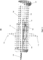
- FIGs 3a-3e show a loading device 300 according to a third alternative embodiment of the present disclosure.
- the loading device 300 comprises two tubular structures 301 and 302, with tubular structure 302 configured to move slidably over tubular structure 301.
- the tubular structures 301 and 302 each have a narrowing inner cavity, with opposing directions of narrowing, as can be seen in Figure 3b .
- Tubular structure 301 has an opening for insertion of a catheter 105. Placement of the implant 103 between tubular structures 301 and 302, followed by the sliding of tubular structure 302 over tubular structure 301, causes the implant 103 to radially compress within the two opposing narrowing cavities and slide into the catheter 105.
- Figure 3c shows a cross-sectional view of the separated tubular structures 301 and 302.
- Figures 4a-4e , 5 , 6 and 7 show catheter 105 comprising members for loading an uncompressed implant 103 onto the catheter 105, included in embodiments of the present invention.
- the catheter 105 comprises a lumen or sheath, and a member within the lumen or sheath that extends distally out of the catheter 105 and attaches itself to an uncompressed implant 103, pulls the implant 103 through a narrowing passage to compress the implant 103, and then continues to pull the now compressed implant 103 into the catheter 105.
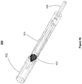
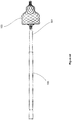
- Figures 4a-4e illustrate a catheter 105 with a slotted rod 601 configured to hold the proximal end (such as a bushing) of a compressible implant 103, : included in an embodiment of the present invention.
- the catheter is inserted through a narrowing passage 602.
- the rod may be a hypotube, a coil, a solid wire, or any other such element that can be rigid.
- the slotted rod 601 is extended distally out of its encasing catheter 105.
- the uncompressed implant 103 is placed within the slot.
- the slotted rod 601 then pulls the implant 103 through the narrowing passage 602 and compresses it (not shown) to a diameter that is small enough to be inserted into the internal lumen of the catheter 105.
- the collapsed implant 103 is pulled into the catheter 105, as shown in Figure 4c .
- the implant 103 can be released from the catheter 105 by extending the rod 601 distally out of the catheter 105, or alternatively by pulling the catheter lumen or sheath back to expose the rod 601.
- the user can twist or turn the rod 601 and disengage the implant 103.
- the rod may comprise a mechanism for more tightly gripping the implant 103.
- a rod 603 is shown comprising a spring 603a and a spring loaded ball 603b to increase the grip on the implant 103.
- the slotted rod 603 is pushed out of its catheter (not shown).
- the bushing of the implant 103 is placed within the slot and the spring loaded ball 603b exerts a gripping pressure against the implant 103, holding it tightly in place.
- the implant 103 is then pulled into the narrowing passage 602 and compressed to a diameter smaller than that of the internal lumen of the catheter (not shown) and further pulled into the catheter.
- the implant 103 can be released again from the catheter by pushing the rod 603 out of the catheter, or alternatively by pulling the catheter lumen or sheath back to expose the rod 603. As described above, once the implant 103 has been deployed into the bronchial passageway of a patient, the user can twist and turn the rod 603 to disengage the implant 103.
- the rod may comprise an attachment mechanism such as a latch mechanism to latch onto the implant 103.
- the rod 604 comprises a latch 604a and is extended distally out of its encasing catheter 105.
- the bushing of the implant 103 is placed within the latch 604a and locked into place.
- the implant 103 is then pulled through the narrowing passage 602 and compressed to a diameter smaller than that of the internal lumen of the catheter 105.
- the implant 103 can be released again from the catheter 105 by pushing the rod 604 out of the catheter 105 (or alternatively by pulling the catheter lumen or sheath back to expose the rod 604) and releasing the latch 604a.
- releasing the latch 604a causes the rod 604 to disengage from and release the implant 103.
- the rod may comprise a loop wire as an attachment mechanism to secure the implant 103 to the rod.
- the rod 605 comprises a loop wire 605a that protrudes out of its encasing catheter 105 and loops around the bushing of the implant 103, pulling the implant 103 into the narrowing passage 602 and compressing it to a diameter smaller than that of the internal lumen of the catheter 105.
- the loop wire 605a may comprise shape memory material such as Nitinol to allow it to release the implant 103 by increasing the slack in the loop wire 605a.
Landscapes
- Health & Medical Sciences (AREA)
- Life Sciences & Earth Sciences (AREA)
- Surgery (AREA)
- Engineering & Computer Science (AREA)
- Biomedical Technology (AREA)
- Animal Behavior & Ethology (AREA)
- Veterinary Medicine (AREA)
- Vascular Medicine (AREA)
- Public Health (AREA)
- Heart & Thoracic Surgery (AREA)
- General Health & Medical Sciences (AREA)
- Molecular Biology (AREA)
- Medical Informatics (AREA)
- Nuclear Medicine, Radiotherapy & Molecular Imaging (AREA)
- Reproductive Health (AREA)
- Cardiology (AREA)
- Oral & Maxillofacial Surgery (AREA)
- Transplantation (AREA)
- Media Introduction/Drainage Providing Device (AREA)
- Prostheses (AREA)
Description
- 1. Field of the Invention. This invention relates generally to implants, and specifically to devices for loading a collapsible implant onto a delivery catheter, and more particularly for loading a collapsible pulmonary implant onto a delivery catheter.
- 2. Description of the Background Art. Collapsible self-expanding implants are well known in the medical device field. Historical medical uses for such implants include maintaining openings in vascular, urinary, biliary, esophageal, and renal tracts, and vena cava filters. Recently, modified pulmonary implants are being contemplated for the treatment of pulmonary disorders. Some such pulmonary devices differ from conventional occlusive devices in that they are designed to constrict, block, or significantly restrict fluid flow in a pulmonary passageway, rather than maintain an opening in it.
- Self-expanding pulmonary implants must be compressed to enable delivery through relatively small and curved body pathways. A delivery device, such as a delivery catheter, retains the pulmonary implant in its radially compressed state as it transports the implant to a treatment site through relevant bodily passageways. There, the implant is released and expands to its non-compressed shape.
- One of the challenges for the delivery of such pulmonary implants is accurately loading the implant onto the delivery catheter without dropping or damaging the device. The physician or nurse attempting to load the implant onto the catheter often finds it difficult to perform the task. Therefore, devices for loading implants onto delivery catheters are desirable.
- Also, implants that are already pre-loaded onto a catheter might lose some of their functionality as they remain on the shelf for extended periods of time before they are used in a patient. Ideally, the device would be maintained in its native state until it is ready to be used in a patient. When ready to be used, the physician should be able to load the implant onto the delivery catheter using a simple maneuver. Furthermore, the implant should be well protected during shipping and transfer until it is ready to be used. A simple system that would meet all the above needs would be highly desirable.
-
U.S. patent No. 6,096,027 discloses an apparatus for loading a stent onto a catheter using a flexible sleeve to encase the stent as it is pulled through a tapered passageway. Commonly assigned publishedU.S. patent application No. 20060162731A1 discloses a loading mandrel positioned within a loading body, wherein the loading mandrel is manipulated to load an occlusal stent into a wide-mouthed end of the loading body and move the occlusal stent to a narrow-mouthed end within the loading body. -
US 6,068,635 relates to a procedure as well as a device for introducing an endoprosthesis into the distal end of a catheter by means of which the endoprosthesis is introduced into a vessel for implantation therein and is released to undergo self expansion by moving the tip of a catheter axially relative to the distal end of an outer catheter. An embodiment of the device comprises a hollow cylindrical housing designed to receive the endoprosthesis, a piston axially displaceable therein which can be brought into engagement with the endoprosthesis, and a nose section arranged at one end of the housing, said nose section being provided with a recess tapering in the direction of an opening, and by means of said recess the endoprosthesis supplied by the piston may be introduced, with compressed diameter and in elongated form, into the distal end of the catheter replaceably arranged on the nose section. -
US 2004/0210248 describes an assembly which delivers an intra-bronchial device into an air passageway. The assembly includes a delivery catheter having a deployment lumen with a distal end arranged to receive the intra-bronchial device in a delivery configuration, and arranged to be passed down a trachea and advanced to a location for deployment of the intra-bronchial device, and to deploy the intra-bronchial device by retracting the deployment catheter. The assembly further includes a bronchial device supply tool associated with the distal end, and arranged to carry the intra-bronchial device in a storage configuration and to load the intra-bronchial device in a delivery configuration into the deployment lumen of distal end, and the intra-bronchial device carried in the supply tool in a storage configuration. An example of the supply tool includes a storage portion, a delivery portion, and a configuration-changing portion coupled between the storage portion and the delivery portion. - The device for loading a collapsible implant according to the invention is defined in claim 1. Preferred embodiments are defined in the dependent claims.
- Devices for loading a collapsible implant onto a delivery catheter are disclosed. A loading device accepts a flexible and self-expanding implant, as well as the distal end of a delivery catheter. The loading device guides the implant through a narrowing passage that feeds into the distal end of the catheter. As the implant passes through the narrowing passage, it is compressed to a diameter that allows the implant to be inserted into the catheter.
- In one aspect, a loading device comprises an outer tubular structure and an inner tubular structure. The outer tubular structure comprises a narrowing passage configured to receive a catheter at one end and a collapsible implant at another end. The inner tubular structure is configured to move slidably and co-axially within the outer tubular structure. The inner tubular structure comprises a carrier pin configured to move within the narrowing passage as the inner tubular structure slides into the outer tubular structure. The sliding of the inner tubular structure into the outer tubular structure causes an implant mounted on the carrier pin to collapse as the implant moves through the narrowing passage and into the distal end of a catheter. Optionally, the outer tubular structure further comprises a grasper to stabilize the catheter for receipt of the collapsible implant, and the internal diameter of the inner tubular structure varies to cause the grasper to first contract and stabilize the catheter, and then expand and release the catheter, as the grasper moves into the inner tubular structure.
- In another aspect, the loading device comprises an outer shaft comprising a narrowing passage leading to an opening for receiving the distal end of a catheter, an opening for accepting a collapsible implant, and two compression members. The first compression member is configured to move slidably within the outer shaft and guides the implant through the narrowing passage, thereby collapsing it. The second compression member then inserts the implant into the catheter.
- In another aspect, the loading device comprises two tubular structures with opposing narrowing inner diameters, with one tubular structure configured to move slidably over the other. Placement of an implant between the structures, followed by sliding one tubular structure over the other, causes the implant to radially compress within the two opposing narrowing cavities.
- In another aspect, a catheter with a slotted rod is configured to hold and pull a collapsible implant through a narrowing passage and into the distal opening of the catheter. In another aspect, the slotted rod comprises a spring loaded ball configured to increase the grip on the implant. In another aspect, the rod comprises a grasping or latching mechanism configured to latch onto the implant as the implant is pulled through the narrowing passage and into the catheter. In another aspect, the rod comprises a loop wire configured to secure the implant as the implant is pulled through the narrowing passage and into the catheter. The loop wire may comprise shape-memory material such as Nitinol to allow it to release the implant by increasing the slack in the loop wire.
- The present invention further provides sterile kits for distributing and storing the system components according to claim 15. The kits will include packaging for holding the components, usually including a primary package which may be a box, pouch, cylinder, or other protective package. The individual system components are usually held within separate sterile containers within the primary package, usually being in pouches, cylinders, or the like. As a particular advantage of the present invention, self-expanding implants may be preloaded within the loading device and held in their uncollapsed configuration, thus reducing the risk of damaging the elastic implant materials prior to loading and implantation. Optionally, the kits may comprise instructions for use setting forth any of the loading methods described herein.
- The invention has other advantages and features which will be more readily apparent from the following detailed description of the invention and the appended claims, when taken in conjunction with the accompanying drawings, in which:
-
Figures 1a-1g show a loading device, in accordance with a first embodiment of the present invention. -
Figure 2 shows an alternative embodiment of the loading tool ; not according to the present invention. -
Figures 3a-3e show another embodiment of a loading tool not according to the present invention. -
Figures 4a-4e illustrate a catheter with a slotted rod configured to hold and pull on the proximal end of a compressible implant. -
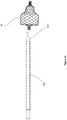
Figure 5 illustrates a catheter with a rod comprising a spring loaded ball to increase the grip on a compressible implant. -
Figure 6 illustrates a catheter with a rod comprising a latch mechanism to secure and pull a compressible implant. -
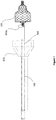
Figure 7 illustrates a catheter with a rod comprising a loop wire to secure and pull an implant. - Although the detailed description contains many specifics, these should not be construed as limiting the scope of the invention but merely as illustrating different examples and aspects of the invention. It should be appreciated that the scope of the invention includes other embodiments not discussed in detail above. Various other modifications, changes and variations which will be apparent to those skilled in the art may be made in the device of the present invention disclosed herein without departing from the scope of the invention defined by the claims.
- Various embodiments of a loading device are disclosed for loading a collapsible pulmonary implant onto a delivery system, in preparation for delivering the implant into the pulmonary airways of a patient. The delivery system may comprise a catheter. Collapsible pulmonary implants are made of memory-shape materials, such as Nitinol, and are compressed to enable delivery through relatively small and curved bodily pathways to the treatment site. Delivery devices, such as catheters, retain the collapsed pulmonary implants in a radially compressed state for delivery to the treatment site, where the implant is released into the airway and regains its non-compressed shape. The present description discloses various embodiments of a loading device that collapses such implants and optionally inserts them onto a delivery catheter. The present description further discloses various embodiments of catheters comprising rods for securing and pulling a collapsible pulmonary implant through a narrowing passage and into the catheter, collapsing the implant before it enters the catheter. As should be obvious to one of ordinary skill in the art, the present embodiments can be used with any implants that are delivered bronchoscopically for inducing atelectasis. Such implants may be restrictive or occlusive in nature, or valve-based.
-
Figures 1a-1g illustrate aloading device 100 according to a preferred embodiment of the present invention. -
Figure 1a shows the assembledloading device 100. An innertubular structure 102 is configured to move slidably into and out of an outertubular structure 101. The innertubular structure 102 is hereinafter also referred to as aplunger 102, and the outertubular structure 101 is hereinafter also referred to as abarrel 101. - The
plunger 102 comprises anoptional cap 107. Acarrier pin 104 may be attached to theplunger 102 itself, or alternatively attached to thecap 107 as is shown in the Figures. A collapsiblepulmonary implant 103 is mounted on thecarrier pin 104, positioned for compression through a narrowing passage and insertion into a catheter. One end of thebarrel 101 is configured to receive theimplant 103 mounted on thecarrier pin 104, and the other end is configured to receive a catheter (as is shown in the additional figures below). As theplunger 102 slides into thebarrel 101, thecarrier pin 104 guides theimplant 103 through thenarrowing passage 106, compressing theimplant 103 and inserting it into the opening at the distal end of the catheter. - The
barrel 101 comprises optional finger rests 110. Finger rests 110 andcap 107 allow a user to place two fingers in the finger rests 110 and hold theloading device 100 while using the thumb or the palm of the hand to slide theplunger 102 into thebarrel 101, similar to using a syringe or a pump, as shown inFigure 1e . -
Figure 1b shows an exploded view of the components of theloading device 100, showing thebarrel 101 with optional finger rests 110, theplunger 102, acap 107, acarrier pin 104, anarrowing passage 106, acatheter passage 109, anoptional grasper 108, and acollapsible implant 103. -
Figures 1c and1d show interior and cross-sectional views of theloading device 100, with acatheter 105 inserted into theloading device 100. As shown, theloading device 100 comprises anarrowing passage 106. Movement of theimplant 103 into thenarrowing passage 106 compresses theimplant 103, thereby reducing its diameter until the diameter is small enough to fit into thecatheter 105. A continuation of the same plunging motion that compresses theimplant 103 also inserts it into thecatheter 105. As shown in Figure Id, thecatheter 105 comes to rest as it comes in contact withindentations 112. A user compresses the loading device, as shown inFigure 1e , thereby causingtubular structure 102 to move intotubular structure 101. - Still referring to
Figures 1c and Id, theloading device 100 optionally comprises agrasper 108. Thegrasper 108 is configured to grasp down on an insertedcatheter 105 upon application of a force, which is provided by the tapered cavity of the plunger 102.This cavity comprises a first section with a reducedinternal diameter 111a and a second section with a largerinternal diameter 111b, as depicted inFigure 1d . - Prior to the
plunger 102 sliding into thebarrel 101, thegrasper 108 is in an open, released state. The sliding of theplunger 102 into thebarrel 101 forces thegrasper 108 through the reduced diameter section of theplunger 102 and causes thegrasper 108 arms to close. As a result, thegrasper 108 grasps and holds down thecatheter 105, thereby stabilizing thecatheter 105 for the insertion of thecompressed implant 103 during the movement of theloading device 100. Upon moving through and exiting the reduced diameter section of theplunger 102 and entering the larger diameter section, thegrasper 108 arms return to their open state, thereby releasing the loadedcatheter 105 and allowing a user to remove thecatheter 105 from theloading device 100. -
Figure 1f shows theloading device 100 in a partially compressed state. Theplunger 102 has moved into thetubular structure 101, and thecarrier pin 104 has guided theimplant 103 through thenarrowing passage 106 and compressed it.Figure 1g shows theloading device 100 in a fully compressed state. When theloading device 100 is fully compressed, i.e., theplunger 102 has completed its travel from the proximal end of thebarrel 101 to the distal end of thebarrel 101, theimplant 103 has been inserted into thecatheter 105, and thegrasper 108 has released thecatheter 105 after passing through the reduced diameter section of theplunger 102. In other words, theloading device 100 has, in one continuous motion, grasped (stabilized) thedelivery catheter 105, loaded theimplant 103 onto thecatheter 105, and released thecatheter 105 when theimplant 103 has been loaded. This enables the user to conveniently load animplant 103 with the least amount of effort and ensure that it is loaded properly. - Optionally, the
loading device 100 is configured to allow a user to visually verify that theimplant 103 is loaded onto thecatheter 105. For example, in one embodiment theplunger 102 and/orbarrel 101 may comprise at least partially transparent material, such as glass or plastic. In another embodiment, thedevice 100 may comprise a cut-away portion serving as a viewing port. - It is an advantageous aspect of the
loading device 100 that it allows for loading theimplant 103 at an accurate and predictable location within thecatheter 105. It is another advantageous aspect of theloading device 100 that it facilitates simple, straightforward, repeatable operation, providing ease of use. It is yet another advantageous aspect of theloading device 100 that it prevents damage to theimplant 103 during shipping, storage, and loading operation. It is yet another advantageous aspect of theloading device 100 that it prevents theimplant 103 from resting on its side over an extended period of time, thereby preventing damage to, or functional degradation of, theimplant 103. One of the most important advantages offered b theloading device 100 is that it prevents insertion of theimplant 103 onto thecatheter 105 in an incorrect (i.e., reversed) distal-proximal orientation. It is yet another advantageous aspect of theloading device 100 that it can be sterilized together with theimplant 103 and separately from thecatheter 105. It is yet another advantageous aspect of theloading device 100 that it prevents damage to thecatheter 105 during loading. Theloading device 100 may be made of light-weight materials, as well as an intuitive form factor,and thus making it easy it to handle. -
Figure 2 shows aloading device 200 according to a second alternative embodiment of the present disclosure.Loading device 200 comprises an elongateouter shaft 208 comprising anarrowing passage 206 leading to anopening 205 for receiving the distal end of a catheter (not shown). Theloading device 200 comprises a firststage compression member 207 configured to move slidably within theouter shaft 208, and a secondstage compression member 204 configured to move slidably within the firststage compression member 207. - The first
stage compression member 207 comprises ahandle 201 protruding through anopening 210 on the side of theouter shaft 208. The secondstage compression member 204 comprises ahandle 202 protruding through anopening 211 of theouter shaft 208. The twocompression members tether 212. - To load a
implant 103 onto acatheter 105 using theloading device 200, theimplant 103 is inserted into through anopening 209 into theloading device 200, and the distal tip of acatheter 105 is inserted into theopening 205. The catheter's tip is secured to theloading device 200 prior to insertion of theimplant 103. - Once the catheter tip is inserted into and secured to the loading device, a user uses handle 201 to slide the first
stage compression member 207 towards the narrowingpassage 206. The firststage compression member 207 guides theimplant 103 through thenarrowing passage 206, thereby compressing theimplant 103. When the firststage compression member 207 completes its range of motion, theimplant 103 is sufficiently compressed to allow the secondstage compression member 204 to insert theimplant 103 into thecatheter 105. Since the two compression members are tethered together, the secondstage compression member 204 follows as the firststage compression member 207 completes its range of motion. At that point, the user uses thehandle 202 to slide the secondstage compression member 204 forward, guiding the now compressedimplant 103 through the remainder of thenarrowing passage 206 and into the opening at the distal end of thecatheter 105. -
Figures 3a-3e show aloading device 300 according to a third alternative embodiment of the present disclosure. Referring toFigure 3a , theloading device 300 comprises twotubular structures tubular structure 302 configured to move slidably overtubular structure 301. Thetubular structures Figure 3b .Tubular structure 301 has an opening for insertion of acatheter 105. Placement of theimplant 103 betweentubular structures tubular structure 302 overtubular structure 301, causes theimplant 103 to radially compress within the two opposing narrowing cavities and slide into thecatheter 105. -
Figure 3c shows a cross-sectional view of the separatedtubular structures tubular structures implant 103 between them and slidestubular structure 302 overtubular structure 301 to compress theimplant 103 and insert it into thecatheter 105, as seen inFigures 3d and3e . -
Figures 4a-4e ,5 ,6 and7 show catheter 105 comprising members for loading anuncompressed implant 103 onto thecatheter 105, included in embodiments of the present invention. In these embodiments, thecatheter 105 comprises a lumen or sheath, and a member within the lumen or sheath that extends distally out of thecatheter 105 and attaches itself to anuncompressed implant 103, pulls theimplant 103 through a narrowing passage to compress theimplant 103, and then continues to pull the now compressedimplant 103 into thecatheter 105. We now turn to describing the various embodiments. -
Figures 4a-4e illustrate acatheter 105 with a slottedrod 601 configured to hold the proximal end (such as a bushing) of acompressible implant 103, : included in an embodiment of the present invention. The catheter is inserted through anarrowing passage 602. In the embodiments described herein, the rod may be a hypotube, a coil, a solid wire, or any other such element that can be rigid. - Referring to
Figure 4a , the slottedrod 601 is extended distally out of its encasingcatheter 105. Referring toFigure 4b , theuncompressed implant 103 is placed within the slot. The slottedrod 601 then pulls theimplant 103 through thenarrowing passage 602 and compresses it (not shown) to a diameter that is small enough to be inserted into the internal lumen of thecatheter 105. Finally, thecollapsed implant 103 is pulled into thecatheter 105, as shown inFigure 4c . - Once compressed and stored within the
catheter 105, theimplant 103 can be released from thecatheter 105 by extending therod 601 distally out of thecatheter 105, or alternatively by pulling the catheter lumen or sheath back to expose therod 601. Referring toFigures 4d and4e , once theimplant 103 has been deployed into the bronchial passageway of a patient, the user can twist or turn therod 601 and disengage theimplant 103. - In an optional embodiment, the rod may comprise a mechanism for more tightly gripping the
implant 103. Referring toFigure 5 , arod 603 is shown comprising aspring 603a and a spring loadedball 603b to increase the grip on theimplant 103. Referring toFigure 5 , the slottedrod 603 is pushed out of its catheter (not shown). To load theimplant 103, the bushing of theimplant 103 is placed within the slot and the spring loadedball 603b exerts a gripping pressure against theimplant 103, holding it tightly in place. Theimplant 103 is then pulled into thenarrowing passage 602 and compressed to a diameter smaller than that of the internal lumen of the catheter (not shown) and further pulled into the catheter. Once compressed, theimplant 103 can be released again from the catheter by pushing therod 603 out of the catheter, or alternatively by pulling the catheter lumen or sheath back to expose therod 603. As described above, once theimplant 103 has been deployed into the bronchial passageway of a patient, the user can twist and turn therod 603 to disengage theimplant 103. - In an alternative embodiment, the rod may comprise an attachment mechanism such as a latch mechanism to latch onto the
implant 103. - Referring to
Figure 6 , therod 604 comprises alatch 604a and is extended distally out of its encasing catheter 105.To load theimplant 103, the bushing of theimplant 103 is placed within thelatch 604a and locked into place. As above, theimplant 103 is then pulled through thenarrowing passage 602 and compressed to a diameter smaller than that of the internal lumen of thecatheter 105. Once compressed, theimplant 103 can be released again from thecatheter 105 by pushing therod 604 out of the catheter 105 (or alternatively by pulling the catheter lumen or sheath back to expose the rod 604) and releasing thelatch 604a. Once theimplant 103 has been deployed into the bronchial passageway of a patient, releasing thelatch 604a causes therod 604 to disengage from and release theimplant 103. - In an alternative embodiment, the rod may comprise a loop wire as an attachment mechanism to secure the
implant 103 to the rod. This is illustrated in the embodiment shown inFigure 7 . Therod 605 comprises aloop wire 605a that protrudes out of its encasingcatheter 105 and loops around the bushing of theimplant 103, pulling theimplant 103 into thenarrowing passage 602 and compressing it to a diameter smaller than that of the internal lumen of thecatheter 105. Theloop wire 605a may comprise shape memory material such as Nitinol to allow it to release theimplant 103 by increasing the slack in theloop wire 605a. - While the above is a complete description of the preferred embodiments of the invention, various alternatives, modifications, and equivalents may be used. Therefore, the above description should not be taken as limiting the scope of the invention which is defined by the appended claims.
Claims (15)
- A device (100) for loading a collapsible implant onto a delivery catheter, comprising:an outer tubular structure (101) with a distal end and a proximal end, the outer tubular structure (101) comprising a narrowing passage (106) configured to receive the delivery catheter (105) at one end and the collapsible implant (103) at another end, the catheter (105) having a distal end;an inner tubular structure (102) configured to move slidably within the outer tubular structure (101), the inner tubular structure (102) comprising a carrier pin (104) configured to move within the narrowing passage (106) as the inner tubular structure (102) slides into the outer tubular structure (101);the carrier pin (104) being configured for mounting the collapsible implant thereon (103)and for guiding the collapsible implant (103) through the narrowing passage (106) and into the distal end of the catheter (105) as the inner tubular structure (102) slides into the outer tubular structure (101); andwherein movement of the inner tubular structure (102) into the outer tubular structure (101) causes the collapsible implant (103) to collapse as it moves through the narrowing passage (106) and into the distal end of the catheter; and whereinthe carrier pin (104) is enclosed by the inner tubular structure (102).
- The device of claim 1, wherein the device comprises at least partially transparent material, and/or a viewing port.
- The device of any one of the preceding claims, wherein the outer tubular structure (101) further comprises a grasper (108) to stabilize the catheter (105) for receipt of the collapsible implant (103).
- The device of claim 3, wherein the internal diameter of the inner tubular structure (102) narrows radially over at least some portion so that the grasper (108) is compressed upon entry of the inner tubular structure (102) into the outer tubular structure (101), thereby causing the grasper (108) to grasp and stabilize the catheter (105).
- The device of claim 4, wherein the internal diameter of the inner tubular structure (102) widens radially for at least some portion, allowing the grasper (108) to expand upon further entry of the inner tubular structure (102) into the outer tubular structure (101), thereby causing the grasper (108) to release the catheter (105).
- A device comprising a delivery system for loading a collapsible implant (103) into a delivery catheter, comprising:a loading device (100) according to any one of the preceding claims; and the delivery catheter (105);wherein compression of the loading device (100) causes one of the tubular structures (101, 102) to move slidably within the other (102, 101), causing the carrier pin (104) to guide the collapsible implant (103) through the narrowing passage (106), collapse it, and insert it into the catheter (105).
- The device of any preceding claim, further comprising:
an implant (103) mounted on the carrier pin (104). - The device of claim 7, wherein the implant (103) is a pulmonary implant.
- The device of claim 8, when dependent on claim 6, wherein the catheter (105) comprises:a lumen; anda rod (601) housed slidably within the lumen, the rod (601) comprising an attachment element to attach to a collapsible pulmonary implant (103) and pull the collapsible pulmonary (103) implant into the lumen.
- The device of claim 9, wherein the attachment element comprises a slot for accepting one end of the collapsible pulmonary implant (103).
- The device of claim 10, wherein the attachment element further comprises a spring loaded ball to provide increased grip on the collapsible pulmonary implant (103).
- The device of claim 10, wherein the attachment element comprises a latch mechanism to latch onto the collapsible pulmonary implant (103).
- The device of claim 10, wherein the attachment element comprises a loop wire to loop around one end of the collapsible pulmonary implant (103).
- The device of claim 13, wherein the loop wire comprises a shape memory material, allowing the catheter (105) to release the collapsible pulmonary implant (103) by increasing the slack in the loop wire
- A kit for loading a collapsible implant (103), comprising:
a device according to claims 7 or 8, when dependent on claim 6, or according to any one of claims 9 to 14; wherein the implant is a self-expanding collapsible implant ; and the kit further comprises packaging holding the loading device (100), implant (103), and delivery catheter (105) in a sterile condition.
Applications Claiming Priority (3)
| Application Number | Priority Date | Filing Date | Title |
|---|---|---|---|
| US89394007P | 2007-03-09 | 2007-03-09 | |
| US12/043,404 US8100959B2 (en) | 2007-03-09 | 2008-03-06 | Loading device for a pulmonary implant |
| PCT/US2008/056289 WO2008112574A2 (en) | 2007-03-09 | 2008-03-07 | Loading a device for a pulmonary implant |
Publications (3)
| Publication Number | Publication Date |
|---|---|
| EP2120821A2 EP2120821A2 (en) | 2009-11-25 |
| EP2120821A4 EP2120821A4 (en) | 2017-01-04 |
| EP2120821B1 true EP2120821B1 (en) | 2020-05-27 |
Family
ID=39742462
Family Applications (1)
| Application Number | Title | Priority Date | Filing Date |
|---|---|---|---|
| EP08743733.1A Active EP2120821B1 (en) | 2007-03-09 | 2008-03-07 | Loading a device for a pulmonary implant |
Country Status (4)
| Country | Link |
|---|---|
| US (1) | US8100959B2 (en) |
| EP (1) | EP2120821B1 (en) |
| JP (1) | JP5528818B2 (en) |
| WO (1) | WO2008112574A2 (en) |
Cited By (13)
| Publication number | Priority date | Publication date | Assignee | Title |
|---|---|---|---|---|
| US10940001B2 (en) | 2012-05-30 | 2021-03-09 | Neovasc Tiara Inc. | Methods and apparatus for loading a prosthesis onto a delivery system |
| US11311376B2 (en) | 2019-06-20 | 2022-04-26 | Neovase Tiara Inc. | Low profile prosthetic mitral valve |
| US11357622B2 (en) | 2016-01-29 | 2022-06-14 | Neovase Tiara Inc. | Prosthetic valve for avoiding obstruction of outflow |
| US11389291B2 (en) | 2013-04-04 | 2022-07-19 | Neovase Tiara Inc. | Methods and apparatus for delivering a prosthetic valve to a beating heart |
| US11413139B2 (en) | 2011-11-23 | 2022-08-16 | Neovasc Tiara Inc. | Sequentially deployed transcatheter mitral valve prosthesis |
| US11419720B2 (en) | 2010-05-05 | 2022-08-23 | Neovasc Tiara Inc. | Transcatheter mitral valve prosthesis |
| US11464631B2 (en) | 2016-11-21 | 2022-10-11 | Neovasc Tiara Inc. | Methods and systems for rapid retraction of a transcatheter heart valve delivery system |
| US11491006B2 (en) | 2019-04-10 | 2022-11-08 | Neovasc Tiara Inc. | Prosthetic valve with natural blood flow |
| US11497602B2 (en) | 2012-02-14 | 2022-11-15 | Neovasc Tiara Inc. | Methods and apparatus for engaging a valve prosthesis with tissue |
| US11602429B2 (en) | 2019-04-01 | 2023-03-14 | Neovasc Tiara Inc. | Controllably deployable prosthetic valve |
| US11737872B2 (en) | 2018-11-08 | 2023-08-29 | Neovasc Tiara Inc. | Ventricular deployment of a transcatheter mitral valve prosthesis |
| US11779742B2 (en) | 2019-05-20 | 2023-10-10 | Neovasc Tiara Inc. | Introducer with hemostasis mechanism |
| US11793640B2 (en) | 2017-08-25 | 2023-10-24 | Neovasc Tiara Inc. | Sequentially deployed transcatheter mitral valve prosthesis |
Families Citing this family (29)
| Publication number | Priority date | Publication date | Assignee | Title |
|---|---|---|---|---|
| DE102005003632A1 (en) | 2005-01-20 | 2006-08-17 | Fraunhofer-Gesellschaft zur Förderung der angewandten Forschung e.V. | Catheter for the transvascular implantation of heart valve prostheses |
| US7896915B2 (en) | 2007-04-13 | 2011-03-01 | Jenavalve Technology, Inc. | Medical device for treating a heart valve insufficiency |
| US8663320B2 (en) * | 2007-12-04 | 2014-03-04 | Cook Medical Technologies Llc | Storage and loading system for implantable medical devices |
| BR112012021347A2 (en) | 2008-02-26 | 2019-09-24 | Jenavalve Tecnology Inc | stent for positioning and anchoring a valve prosthesis at an implantation site in a patient's heart |
| US9044318B2 (en) | 2008-02-26 | 2015-06-02 | Jenavalve Technology Gmbh | Stent for the positioning and anchoring of a valvular prosthesis |
| CN102300509A (en) * | 2008-12-19 | 2011-12-28 | 泰科保健集团有限合伙公司 | Method And Apparatus For Storage And/or Introduction Of Implant For Hollow Anatomical Structure |
| WO2011014814A2 (en) * | 2009-07-30 | 2011-02-03 | Boston Scientific Scimed, Inc. | Stent delivery system |
| WO2011147849A1 (en) | 2010-05-25 | 2011-12-01 | Jenavalve Technology Inc. | Prosthetic heart valve and transcatheter delivered endoprosthesis comprising a prosthetic heart valve and a stent |
| AU2011302641B2 (en) | 2010-09-17 | 2014-10-02 | St. Jude Medical, Cardiology Division, Inc. | Assembly and method for loading a self-expanding collapsible heart valve |
| WO2012106491A1 (en) * | 2011-02-02 | 2012-08-09 | St. Jude Medical, Inc. | System and method for loading a collapsile heart valve into a delivery device |
| US9155619B2 (en) * | 2011-02-25 | 2015-10-13 | Edwards Lifesciences Corporation | Prosthetic heart valve delivery apparatus |
| AU2012286789B2 (en) | 2011-07-28 | 2016-10-27 | St. Jude Medical, Cardiology Division, Inc. | System for loading a collapsible heart valve |
| US8893370B2 (en) | 2011-07-28 | 2014-11-25 | St. Jude Medical, Cardiology Division, Inc. | System for loading a collapsible heart valve |
| EP2758010B1 (en) | 2011-09-23 | 2017-02-08 | Pulmonx, Inc | Implant loading system |
| WO2013045262A1 (en) * | 2011-09-30 | 2013-04-04 | Jenavalve Technology Inc. | System and method for loading a stent into a medical delivery system |
| EP2768432A1 (en) | 2011-10-21 | 2014-08-27 | JenaValve Technology Inc. | Catheter system for introducing an expandable heart valve stent into the body of a patient, insertion system with a catheter system and medical device for treatment of a heart valve defect |
| EP2849678B1 (en) | 2012-05-16 | 2022-08-10 | JenaValve Technology, Inc. | Catheter delivery system for introducing an expandable heart valve prosthesis and medical device for the treatment of a heart valve defect |
| CH706684A1 (en) * | 2012-06-28 | 2013-12-31 | Qvanteq Ag | Packaging and transfer system for implant application. |
| US20140277341A1 (en) * | 2013-03-15 | 2014-09-18 | Cook Medical Technologies Llc | Wireless medical device release mechanism |
| EP4098226A1 (en) | 2013-08-30 | 2022-12-07 | JenaValve Technology, Inc. | Endoprosthesis comprising a radially collapsible frame and a prosthetic valve |
| US10182910B2 (en) * | 2013-10-23 | 2019-01-22 | Biotronik Ag | Method for fitting an implant to a catheter |
| US10925611B2 (en) * | 2015-01-20 | 2021-02-23 | Neurogami Medical, Inc. | Packaging for surgical implant |
| EP3288495B1 (en) | 2015-05-01 | 2019-09-25 | JenaValve Technology, Inc. | Device with reduced pacemaker rate in heart valve replacement |
| US10926093B2 (en) * | 2016-05-05 | 2021-02-23 | Pacesetter, Inc. | System and method for loading a leadless pacemaker onto a catheter-based delivery system |
| EP4183371A1 (en) | 2016-05-13 | 2023-05-24 | JenaValve Technology, Inc. | Heart valve prosthesis delivery system and method for delivery of heart valve prosthesis with introducer sheath and loading system |
| JP7094965B2 (en) | 2017-01-27 | 2022-07-04 | イエナバルブ テクノロジー インク | Heart valve imitation |
| US10722357B2 (en) | 2017-07-18 | 2020-07-28 | St. Jude Medical, Cardiology Division, Inc. | Flushable loading base |
| CN114630627A (en) | 2019-11-04 | 2022-06-14 | 柯惠有限合伙公司 | Devices, systems, and methods for treating intracranial aneurysms |
| US11974917B2 (en) * | 2019-12-20 | 2024-05-07 | Medtronic Vascular, Inc. | Hydraulic crimping device |
Family Cites Families (69)
| Publication number | Priority date | Publication date | Assignee | Title |
|---|---|---|---|---|
| AT244495B (en) * | 1963-04-19 | 1966-01-10 | Willy Ruesch Fa | Catheters for ventilation and / or anesthesia |
| US3498286A (en) * | 1966-09-21 | 1970-03-03 | American Optical Corp | Catheters |
| US3542026A (en) * | 1968-07-23 | 1970-11-24 | Billy M Bledsoe | Thoracostomy device |
| US3669098A (en) * | 1968-10-05 | 1972-06-13 | Olympus Optical Co | Endotracheal tube |
| US3677262A (en) * | 1970-07-23 | 1972-07-18 | Henry J Zukowski | Surgical instrument illuminating endotracheal tube inserter |
| US3776222A (en) * | 1971-12-23 | 1973-12-04 | Lurosso A | Fiber optic entubator and method of entubation of the trachea through the nasopharynx |
| US3866599A (en) * | 1972-01-21 | 1975-02-18 | Univ Washington | Fiberoptic catheter |
| US3913568A (en) * | 1973-01-22 | 1975-10-21 | American Optical Corp | Nasopharyngoscope |
| US4041936A (en) * | 1975-04-23 | 1977-08-16 | Medical Engineering Corporation | Bronchoscopy tube |
| US4327721A (en) * | 1978-07-07 | 1982-05-04 | George Hanover | Endotracheal tube with topical agent delivery system and method of using the same |
| US4327720A (en) * | 1979-01-22 | 1982-05-04 | Bronson Paul A | Esophageal-endotracheal airway |
| JPS6010740B2 (en) * | 1981-05-07 | 1985-03-19 | 宏司 井上 | Endotracheal tube for unilateral lung ventilation |
| US4468216A (en) * | 1982-05-20 | 1984-08-28 | Rudolph Muto | Irrigation suction catheter |
| US4567882A (en) * | 1982-12-06 | 1986-02-04 | Vanderbilt University | Method for locating the illuminated tip of an endotracheal tube |
| EP0203124B1 (en) * | 1984-11-15 | 1991-06-05 | NAZARI, Stefano | Device for selective bronchial intubation and separate lung ventilation |
| JPS61250605A (en) * | 1985-04-27 | 1986-11-07 | Power Reactor & Nuclear Fuel Dev Corp | Image fiber with optical waveguide |
| US4716896A (en) * | 1986-08-01 | 1988-01-05 | Ackrad Laboratories | Bronchial catheter |
| US4976710A (en) * | 1987-01-28 | 1990-12-11 | Mackin Robert A | Working well balloon method |
| US4961738A (en) * | 1987-01-28 | 1990-10-09 | Mackin Robert A | Angioplasty catheter with illumination and visualization within angioplasty balloon |
| US4784133A (en) * | 1987-01-28 | 1988-11-15 | Mackin Robert A | Working well balloon angioscope and method |
| US4742819A (en) * | 1987-03-23 | 1988-05-10 | George Gordon P | Intubating scope with camera and screen |
| DE3719250A1 (en) * | 1987-06-10 | 1988-12-22 | Kellner Hans Joerg Dr Med | ENDOSCOPE |
| DE3736680C1 (en) * | 1987-10-29 | 1988-10-27 | Didier Werke Ag | Process for the production of carbon-bonded refractory molded parts |
| US4846153A (en) * | 1988-06-10 | 1989-07-11 | George Berci | Intubating video endoscope |
| US4850371A (en) * | 1988-06-13 | 1989-07-25 | Broadhurst John H | Novel endotracheal tube and mass spectrometer |
| US4958932A (en) * | 1988-08-18 | 1990-09-25 | Mcdonnell Douglas Corporation | Optical measuring apparatus |
| US4949716A (en) * | 1988-10-31 | 1990-08-21 | Medical Devices, Inc. | Nasal intubation adjunct |
| US4955375A (en) * | 1989-01-23 | 1990-09-11 | Ricardo Martinez | Endotracheal tube with channel for delivering drugs |
| US5562608A (en) * | 1989-08-28 | 1996-10-08 | Biopulmonics, Inc. | Apparatus for pulmonary delivery of drugs with simultaneous liquid lavage and ventilation |
| US5207220A (en) * | 1989-12-12 | 1993-05-04 | Burroughs Wellcome Co. | Method for administering pharmaceuticals, including liquid surfactant, to the lungs |
| US5146916A (en) * | 1990-01-05 | 1992-09-15 | Catalani Angelo S | Endotracheal tube incorporating a drug-irrigation device |
| US5056529A (en) * | 1990-04-03 | 1991-10-15 | Groot William J De | Apparatus and method for performing a transbroncheal biopsy |
| US5143062A (en) * | 1990-10-26 | 1992-09-01 | Mallinckrodt Medical, Inc. | Endotracheal tube having irrigation means |
| US5246012A (en) | 1990-12-21 | 1993-09-21 | Ballard Medical Products | Bronchoalveolar lavage catheter |
| US5285778A (en) * | 1991-04-19 | 1994-02-15 | Mackin Robert A | Endotracheal tube wih fibers optic illumination and viewing and auxiliary tube |
| US5331947A (en) * | 1992-05-01 | 1994-07-26 | Shturman Cardiology Systems, Inc. | Inflatable sheath for introduction of ultrasonic catheter through the lumen of a fiber optic endoscope |
| DE4222220A1 (en) * | 1992-07-07 | 1994-01-13 | Deutsche Aerospace | Procedure for measuring and regulating the pressure in the sealing sleeve of a tracheal tube |
| US5499625A (en) * | 1994-01-27 | 1996-03-19 | The Kendall Company | Esophageal-tracheal double lumen airway |
| US5645519A (en) * | 1994-03-18 | 1997-07-08 | Jai S. Lee | Endoscopic instrument for controlled introduction of tubular members in the body and methods therefor |
| US5840064A (en) * | 1994-03-31 | 1998-11-24 | United States Surgical Corporation | Method and apparatus for treating stenosis or other constriction in a bodily conduit |
| GB9411215D0 (en) | 1994-06-04 | 1994-07-27 | Brain Archibald Ian Jeremy | A fibreoptic intubating laryngeal mask airway |
| US5642730A (en) * | 1994-06-17 | 1997-07-01 | Trudell Medical Limited | Catheter system for delivery of aerosolized medicine for use with pressurized propellant canister |
| US5477851A (en) * | 1995-01-26 | 1995-12-26 | Callaghan; Eric B. | Laryngeal mask assembly and method for removing same |
| US5598840A (en) * | 1995-03-17 | 1997-02-04 | Sorenson Critical Care, Inc. | Apparatus and method for ventilation and aspiration |
| US5660175A (en) * | 1995-08-21 | 1997-08-26 | Dayal; Bimal | Endotracheal device |
| WO1997013471A1 (en) * | 1995-10-13 | 1997-04-17 | Transvascular, Inc. | A device, system and method for interstitial transvascular intervention |
| US5653231A (en) * | 1995-11-28 | 1997-08-05 | Medcare Medical Group, Inc. | Tracheostomy length single use suction catheter |
| US5752921A (en) * | 1996-01-11 | 1998-05-19 | Korr Medical Technologies, Inc. | Method and apparatus for determining tracheal pressure |
| US5682880A (en) * | 1996-07-26 | 1997-11-04 | Brain; Archibald Ian Jeremy | Laryngeal-mask airway with guide element, stiffener, and fiberoptic access |
| US5725519A (en) * | 1996-09-30 | 1998-03-10 | Medtronic Instent Israel Ltd. | Stent loading device for a balloon catheter |
| GB2324729B (en) | 1997-04-30 | 2002-01-02 | Bradford Hospitals Nhs Trust | Lung treatment device |
| US5957949A (en) * | 1997-05-01 | 1999-09-28 | World Medical Manufacturing Corp. | Percutaneous placement valve stent |
| US5984944A (en) * | 1997-09-12 | 1999-11-16 | B. Braun Medical, Inc. | Introducer for an expandable vascular occlusion device |
| US5992000A (en) * | 1997-10-16 | 1999-11-30 | Scimed Life Systems, Inc. | Stent crimper |
| JP2002508209A (en) * | 1997-12-15 | 2002-03-19 | プロリフィックス メディカル, インコーポレイテッド | Vascular stent for reduction of restenosis |
| EP0941713B1 (en) * | 1998-03-04 | 2004-11-03 | Schneider (Europe) GmbH | Device to insert an endoprosthesis into a catheter shaft |
| US5974652A (en) * | 1998-05-05 | 1999-11-02 | Advanced Cardiovascular Systems, Inc. | Method and apparatus for uniformly crimping a stent onto a catheter |
| US6132458A (en) * | 1998-05-15 | 2000-10-17 | American Medical Systems, Inc. | Method and device for loading a stent |
| US6096027A (en) * | 1998-09-30 | 2000-08-01 | Impra, Inc., A Subsidiary Of C.R. Bard, Inc. | Bag enclosed stent loading apparatus |
| US6287290B1 (en) * | 1999-07-02 | 2001-09-11 | Pulmonx | Methods, systems, and kits for lung volume reduction |
| US6398775B1 (en) * | 1999-10-21 | 2002-06-04 | Pulmonx | Apparatus and method for isolated lung access |
| GB2369575A (en) * | 2000-04-20 | 2002-06-05 | Salviac Ltd | An embolic protection system |
| US6585639B1 (en) * | 2000-10-27 | 2003-07-01 | Pulmonx | Sheath and method for reconfiguring lung viewing scope |
| US6527761B1 (en) * | 2000-10-27 | 2003-03-04 | Pulmonx, Inc. | Methods and devices for obstructing and aspirating lung tissue segments |
| US20030083730A1 (en) * | 2001-10-25 | 2003-05-01 | Scimed Life Systems, Inc. | Loading cartridge for self-expanding stent |
| US20030225445A1 (en) * | 2002-05-14 | 2003-12-04 | Derus Patricia M. | Surgical stent delivery devices and methods |
| US20040210248A1 (en) * | 2003-03-12 | 2004-10-21 | Spiration, Inc. | Apparatus, method and assembly for delivery of intra-bronchial devices |
| US20060162731A1 (en) * | 2004-11-16 | 2006-07-27 | Pulmonx | Pulmonary occlusal stent delivery catheter, loading system and methods of use |
| US8753384B2 (en) * | 2006-05-19 | 2014-06-17 | Boston Scientific Scimed, Inc. | Apparatus and method for loading and delivering a stent |
-
2008
- 2008-03-06 US US12/043,404 patent/US8100959B2/en active Active
- 2008-03-07 WO PCT/US2008/056289 patent/WO2008112574A2/en active Application Filing
- 2008-03-07 JP JP2009553704A patent/JP5528818B2/en active Active
- 2008-03-07 EP EP08743733.1A patent/EP2120821B1/en active Active
Non-Patent Citations (1)
| Title |
|---|
| None * |
Cited By (16)
| Publication number | Priority date | Publication date | Assignee | Title |
|---|---|---|---|---|
| US11419720B2 (en) | 2010-05-05 | 2022-08-23 | Neovasc Tiara Inc. | Transcatheter mitral valve prosthesis |
| US11413139B2 (en) | 2011-11-23 | 2022-08-16 | Neovasc Tiara Inc. | Sequentially deployed transcatheter mitral valve prosthesis |
| US11497602B2 (en) | 2012-02-14 | 2022-11-15 | Neovasc Tiara Inc. | Methods and apparatus for engaging a valve prosthesis with tissue |
| US11617650B2 (en) | 2012-05-30 | 2023-04-04 | Neovasc Tiara Inc. | Methods and apparatus for loading a prosthesis onto a delivery system |
| US11389294B2 (en) | 2012-05-30 | 2022-07-19 | Neovasc Tiara Inc. | Methods and apparatus for loading a prosthesis onto a delivery system |
| US10940001B2 (en) | 2012-05-30 | 2021-03-09 | Neovasc Tiara Inc. | Methods and apparatus for loading a prosthesis onto a delivery system |
| US11389291B2 (en) | 2013-04-04 | 2022-07-19 | Neovase Tiara Inc. | Methods and apparatus for delivering a prosthetic valve to a beating heart |
| US11357622B2 (en) | 2016-01-29 | 2022-06-14 | Neovase Tiara Inc. | Prosthetic valve for avoiding obstruction of outflow |
| US11464631B2 (en) | 2016-11-21 | 2022-10-11 | Neovasc Tiara Inc. | Methods and systems for rapid retraction of a transcatheter heart valve delivery system |
| US11793640B2 (en) | 2017-08-25 | 2023-10-24 | Neovasc Tiara Inc. | Sequentially deployed transcatheter mitral valve prosthesis |
| US11737872B2 (en) | 2018-11-08 | 2023-08-29 | Neovasc Tiara Inc. | Ventricular deployment of a transcatheter mitral valve prosthesis |
| US11602429B2 (en) | 2019-04-01 | 2023-03-14 | Neovasc Tiara Inc. | Controllably deployable prosthetic valve |
| US11491006B2 (en) | 2019-04-10 | 2022-11-08 | Neovasc Tiara Inc. | Prosthetic valve with natural blood flow |
| US11779742B2 (en) | 2019-05-20 | 2023-10-10 | Neovasc Tiara Inc. | Introducer with hemostasis mechanism |
| US11311376B2 (en) | 2019-06-20 | 2022-04-26 | Neovase Tiara Inc. | Low profile prosthetic mitral valve |
| US11931254B2 (en) | 2019-06-20 | 2024-03-19 | Neovasc Tiara Inc. | Low profile prosthetic mitral valve |
Also Published As
| Publication number | Publication date |
|---|---|
| EP2120821A4 (en) | 2017-01-04 |
| JP5528818B2 (en) | 2014-06-25 |
| WO2008112574A2 (en) | 2008-09-18 |
| JP2010520803A (en) | 2010-06-17 |
| WO2008112574A3 (en) | 2008-10-30 |
| US20080221703A1 (en) | 2008-09-11 |
| EP2120821A2 (en) | 2009-11-25 |
| US8100959B2 (en) | 2012-01-24 |
Similar Documents
| Publication | Publication Date | Title |
|---|---|---|
| EP2120821B1 (en) | Loading a device for a pulmonary implant | |
| EP1599246B1 (en) | Medical device delivery system | |
| US10034670B2 (en) | Medical implant detachment mechanism and introducer assembly | |
| JP6300821B2 (en) | Stent applicator | |
| EP2419041B1 (en) | Implant delivery system | |
| US8641749B2 (en) | Stent delivery system | |
| EP1800624B1 (en) | Spring-biased injector for an intraocular lens | |
| US8043352B2 (en) | Medical device delivery system with captive inner member | |
| US20030225445A1 (en) | Surgical stent delivery devices and methods | |
| US10159489B2 (en) | Systems and methods for delivering multiple embolization coils | |
| EP2645945B1 (en) | Device for retrieving a body from a tubular structure | |
| JP2010536418A (en) | Placement device | |
| EP1832250A1 (en) | Stent extractor | |
| WO2003092782A1 (en) | Indwelling tube guide device | |
| EP4193936A1 (en) | Implantable medical device detachment system with retractable mechanical release mechanism | |
| MXPA96004364A (en) | Method and apparatus for introducing a prote |
Legal Events
| Date | Code | Title | Description |
|---|---|---|---|
| PUAI | Public reference made under article 153(3) epc to a published international application that has entered the european phase |
Free format text: ORIGINAL CODE: 0009012 |
|
| 17P | Request for examination filed |
Effective date: 20090911 |
|
| AK | Designated contracting states |
Kind code of ref document: A2 Designated state(s): AT BE BG CH CY CZ DE DK EE ES FI FR GB GR HR HU IE IS IT LI LT LU LV MC MT NL NO PL PT RO SE SI SK TR |
|
| DAX | Request for extension of the european patent (deleted) | ||
| RAP1 | Party data changed (applicant data changed or rights of an application transferred) |
Owner name: PULMONX CORPORATION |
|
| A4 | Supplementary search report drawn up and despatched |
Effective date: 20161205 |
|
| RIC1 | Information provided on ipc code assigned before grant |
Ipc: A61B 17/12 20060101ALI20161129BHEP Ipc: A61F 11/00 20060101AFI20161129BHEP Ipc: A61F 2/04 20060101ALI20161129BHEP |
|
| GRAP | Despatch of communication of intention to grant a patent |
Free format text: ORIGINAL CODE: EPIDOSNIGR1 |
|
| STAA | Information on the status of an ep patent application or granted ep patent |
Free format text: STATUS: GRANT OF PATENT IS INTENDED |
|
| RIC1 | Information provided on ipc code assigned before grant |
Ipc: A61F 2/04 20130101ALI20191115BHEP Ipc: A61F 2/95 20130101ALN20191115BHEP Ipc: A61F 11/00 20060101AFI20191115BHEP Ipc: A61F 2/24 20060101ALI20191115BHEP Ipc: A61B 17/12 20060101ALI20191115BHEP Ipc: A61B 17/00 20060101ALN20191115BHEP |
|
| RIC1 | Information provided on ipc code assigned before grant |
Ipc: A61F 11/00 20060101AFI20191202BHEP Ipc: A61F 2/95 20130101ALN20191202BHEP Ipc: A61F 2/24 20060101ALI20191202BHEP Ipc: A61B 17/00 20060101ALN20191202BHEP Ipc: A61F 2/04 20130101ALI20191202BHEP Ipc: A61B 17/12 20060101ALI20191202BHEP |
|
| INTG | Intention to grant announced |
Effective date: 20191216 |
|
| GRAS | Grant fee paid |
Free format text: ORIGINAL CODE: EPIDOSNIGR3 |
|
| GRAA | (expected) grant |
Free format text: ORIGINAL CODE: 0009210 |
|
| STAA | Information on the status of an ep patent application or granted ep patent |
Free format text: STATUS: THE PATENT HAS BEEN GRANTED |
|
| AK | Designated contracting states |
Kind code of ref document: B1 Designated state(s): AT BE BG CH CY CZ DE DK EE ES FI FR GB GR HR HU IE IS IT LI LT LU LV MC MT NL NO PL PT RO SE SI SK TR |
|
| REG | Reference to a national code |
Ref country code: GB Ref legal event code: FG4D |
|
| REG | Reference to a national code |
Ref country code: CH Ref legal event code: EP |
|
| REG | Reference to a national code |
Ref country code: DE Ref legal event code: R096 Ref document number: 602008062767 Country of ref document: DE |
|
| REG | Reference to a national code |
Ref country code: AT Ref legal event code: REF Ref document number: 1273763 Country of ref document: AT Kind code of ref document: T Effective date: 20200615 |
|
| REG | Reference to a national code |
Ref country code: LT Ref legal event code: MG4D |
|
| PG25 | Lapsed in a contracting state [announced via postgrant information from national office to epo] |
Ref country code: SE Free format text: LAPSE BECAUSE OF FAILURE TO SUBMIT A TRANSLATION OF THE DESCRIPTION OR TO PAY THE FEE WITHIN THE PRESCRIBED TIME-LIMIT Effective date: 20200527 Ref country code: IS Free format text: LAPSE BECAUSE OF FAILURE TO SUBMIT A TRANSLATION OF THE DESCRIPTION OR TO PAY THE FEE WITHIN THE PRESCRIBED TIME-LIMIT Effective date: 20200927 Ref country code: GR Free format text: LAPSE BECAUSE OF FAILURE TO SUBMIT A TRANSLATION OF THE DESCRIPTION OR TO PAY THE FEE WITHIN THE PRESCRIBED TIME-LIMIT Effective date: 20200828 Ref country code: NO Free format text: LAPSE BECAUSE OF FAILURE TO SUBMIT A TRANSLATION OF THE DESCRIPTION OR TO PAY THE FEE WITHIN THE PRESCRIBED TIME-LIMIT Effective date: 20200827 Ref country code: FI Free format text: LAPSE BECAUSE OF FAILURE TO SUBMIT A TRANSLATION OF THE DESCRIPTION OR TO PAY THE FEE WITHIN THE PRESCRIBED TIME-LIMIT Effective date: 20200527 Ref country code: LT Free format text: LAPSE BECAUSE OF FAILURE TO SUBMIT A TRANSLATION OF THE DESCRIPTION OR TO PAY THE FEE WITHIN THE PRESCRIBED TIME-LIMIT Effective date: 20200527 Ref country code: PT Free format text: LAPSE BECAUSE OF FAILURE TO SUBMIT A TRANSLATION OF THE DESCRIPTION OR TO PAY THE FEE WITHIN THE PRESCRIBED TIME-LIMIT Effective date: 20200928 |
|
| REG | Reference to a national code |
Ref country code: NL Ref legal event code: MP Effective date: 20200527 |
|
| PG25 | Lapsed in a contracting state [announced via postgrant information from national office to epo] |
Ref country code: LV Free format text: LAPSE BECAUSE OF FAILURE TO SUBMIT A TRANSLATION OF THE DESCRIPTION OR TO PAY THE FEE WITHIN THE PRESCRIBED TIME-LIMIT Effective date: 20200527 Ref country code: HR Free format text: LAPSE BECAUSE OF FAILURE TO SUBMIT A TRANSLATION OF THE DESCRIPTION OR TO PAY THE FEE WITHIN THE PRESCRIBED TIME-LIMIT Effective date: 20200527 Ref country code: BG Free format text: LAPSE BECAUSE OF FAILURE TO SUBMIT A TRANSLATION OF THE DESCRIPTION OR TO PAY THE FEE WITHIN THE PRESCRIBED TIME-LIMIT Effective date: 20200827 |
|
| REG | Reference to a national code |
Ref country code: AT Ref legal event code: MK05 Ref document number: 1273763 Country of ref document: AT Kind code of ref document: T Effective date: 20200527 |
|
| PG25 | Lapsed in a contracting state [announced via postgrant information from national office to epo] |
Ref country code: NL Free format text: LAPSE BECAUSE OF FAILURE TO SUBMIT A TRANSLATION OF THE DESCRIPTION OR TO PAY THE FEE WITHIN THE PRESCRIBED TIME-LIMIT Effective date: 20200527 |
|
| PG25 | Lapsed in a contracting state [announced via postgrant information from national office to epo] |
Ref country code: EE Free format text: LAPSE BECAUSE OF FAILURE TO SUBMIT A TRANSLATION OF THE DESCRIPTION OR TO PAY THE FEE WITHIN THE PRESCRIBED TIME-LIMIT Effective date: 20200527 Ref country code: DK Free format text: LAPSE BECAUSE OF FAILURE TO SUBMIT A TRANSLATION OF THE DESCRIPTION OR TO PAY THE FEE WITHIN THE PRESCRIBED TIME-LIMIT Effective date: 20200527 Ref country code: ES Free format text: LAPSE BECAUSE OF FAILURE TO SUBMIT A TRANSLATION OF THE DESCRIPTION OR TO PAY THE FEE WITHIN THE PRESCRIBED TIME-LIMIT Effective date: 20200527 Ref country code: IT Free format text: LAPSE BECAUSE OF FAILURE TO SUBMIT A TRANSLATION OF THE DESCRIPTION OR TO PAY THE FEE WITHIN THE PRESCRIBED TIME-LIMIT Effective date: 20200527 Ref country code: AT Free format text: LAPSE BECAUSE OF FAILURE TO SUBMIT A TRANSLATION OF THE DESCRIPTION OR TO PAY THE FEE WITHIN THE PRESCRIBED TIME-LIMIT Effective date: 20200527 Ref country code: CZ Free format text: LAPSE BECAUSE OF FAILURE TO SUBMIT A TRANSLATION OF THE DESCRIPTION OR TO PAY THE FEE WITHIN THE PRESCRIBED TIME-LIMIT Effective date: 20200527 Ref country code: RO Free format text: LAPSE BECAUSE OF FAILURE TO SUBMIT A TRANSLATION OF THE DESCRIPTION OR TO PAY THE FEE WITHIN THE PRESCRIBED TIME-LIMIT Effective date: 20200527 |
|
| PG25 | Lapsed in a contracting state [announced via postgrant information from national office to epo] |
Ref country code: PL Free format text: LAPSE BECAUSE OF FAILURE TO SUBMIT A TRANSLATION OF THE DESCRIPTION OR TO PAY THE FEE WITHIN THE PRESCRIBED TIME-LIMIT Effective date: 20200527 Ref country code: SK Free format text: LAPSE BECAUSE OF FAILURE TO SUBMIT A TRANSLATION OF THE DESCRIPTION OR TO PAY THE FEE WITHIN THE PRESCRIBED TIME-LIMIT Effective date: 20200527 |
|
| REG | Reference to a national code |
Ref country code: DE Ref legal event code: R097 Ref document number: 602008062767 Country of ref document: DE |
|
| PLBE | No opposition filed within time limit |
Free format text: ORIGINAL CODE: 0009261 |
|
| STAA | Information on the status of an ep patent application or granted ep patent |
Free format text: STATUS: NO OPPOSITION FILED WITHIN TIME LIMIT |
|
| 26N | No opposition filed |
Effective date: 20210302 |
|
| PG25 | Lapsed in a contracting state [announced via postgrant information from national office to epo] |
Ref country code: SI Free format text: LAPSE BECAUSE OF FAILURE TO SUBMIT A TRANSLATION OF THE DESCRIPTION OR TO PAY THE FEE WITHIN THE PRESCRIBED TIME-LIMIT Effective date: 20200527 |
|
| PG25 | Lapsed in a contracting state [announced via postgrant information from national office to epo] |
Ref country code: MC Free format text: LAPSE BECAUSE OF FAILURE TO SUBMIT A TRANSLATION OF THE DESCRIPTION OR TO PAY THE FEE WITHIN THE PRESCRIBED TIME-LIMIT Effective date: 20200527 |
|
| REG | Reference to a national code |
Ref country code: CH Ref legal event code: PL |
|
| REG | Reference to a national code |
Ref country code: BE Ref legal event code: MM Effective date: 20210331 |
|
| PG25 | Lapsed in a contracting state [announced via postgrant information from national office to epo] |
Ref country code: CH Free format text: LAPSE BECAUSE OF NON-PAYMENT OF DUE FEES Effective date: 20210331 Ref country code: LI Free format text: LAPSE BECAUSE OF NON-PAYMENT OF DUE FEES Effective date: 20210331 Ref country code: LU Free format text: LAPSE BECAUSE OF NON-PAYMENT OF DUE FEES Effective date: 20210307 Ref country code: IE Free format text: LAPSE BECAUSE OF NON-PAYMENT OF DUE FEES Effective date: 20210307 |
|
| PG25 | Lapsed in a contracting state [announced via postgrant information from national office to epo] |
Ref country code: BE Free format text: LAPSE BECAUSE OF NON-PAYMENT OF DUE FEES Effective date: 20210331 |
|
| PGFP | Annual fee paid to national office [announced via postgrant information from national office to epo] |
Ref country code: FR Payment date: 20230321 Year of fee payment: 16 |
|
| PG25 | Lapsed in a contracting state [announced via postgrant information from national office to epo] |
Ref country code: HU Free format text: LAPSE BECAUSE OF FAILURE TO SUBMIT A TRANSLATION OF THE DESCRIPTION OR TO PAY THE FEE WITHIN THE PRESCRIBED TIME-LIMIT; INVALID AB INITIO Effective date: 20080307 Ref country code: CY Free format text: LAPSE BECAUSE OF FAILURE TO SUBMIT A TRANSLATION OF THE DESCRIPTION OR TO PAY THE FEE WITHIN THE PRESCRIBED TIME-LIMIT Effective date: 20200527 |
|
| P01 | Opt-out of the competence of the unified patent court (upc) registered |
Effective date: 20230912 |
|
| PGFP | Annual fee paid to national office [announced via postgrant information from national office to epo] |
Ref country code: DE Payment date: 20240322 Year of fee payment: 17 Ref country code: GB Payment date: 20240325 Year of fee payment: 17 |